1
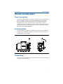
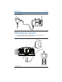
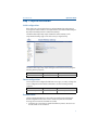
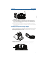
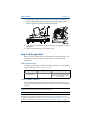
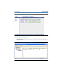
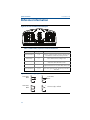
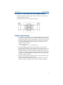
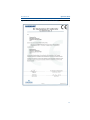
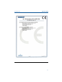
Quick Start Guide 00825-0100-4848, Rev DA December 2014 Rosemount 848T Wireless Temperature Transmitter Quick Start Guide December 2014 NOTICE This guide provides basic guidelines for the Rosemount 848T. It does not provide instructions for detailed configuration, diagnostics, maintenance, service, troubleshooting, or installations. Refer to the Rosemount 848T reference manual (document number 00809-0100-4848) for more instruction. The manual and this guide are also available electronically on www.rosemount.com. Explosions could result in death or serious injury. Installation of this transmitter in an explosive environment must be in accordance with the appropriate local, national, and international standards, codes, and practices. Review the Product Certifications section for any restrictions associated with a safe installation. Before connecting a Field Communicator in an explosive atmosphere, ensure the instruments are installed in accordance with intrinsically safe or non-incendive field wiring practices. Electrical shock can result in death or serious injury. Avoid contact with the leads and terminals. High voltage that may be present on leads can cause electrical shock. This device complies with Part 15 of the FCC Rules. Operation is subject to the following conditions. This device may not cause harmful interference. This device must accept any interference received, including interference that may cause undesired operation. This device must be installed to ensure a minimum antenna separation distance of 20 cm from all persons. The power module may be replaced in a hazardous area. The power module has surface resistivity greater than one gigaohm and must be properly installed in the wireless device enclosure. Care must be taken during transportation to and from the point of installation to prevent electrostatic charge build-up. NOTICE Shipping considerations for wireless products: The unit was shipped to you without the power module installed. Remove the power module prior to shipping the unit. Each power module contains two “C” size primary lithium batteries. Primary lithium batteries are regulated in transportation by the U.S. Department of Transportation, and are also covered by IATA (International Air Transport Association), ICAO (International Civil Aviation Organization), and ARD (European Ground Transportation of Dangerous Goods). It is the responsibility of the shipper to ensure compliance with these or any other local requirements. Please consult current regulations and requirements before shipping. Contents Wireless Considerations . . . . . . . . . . . . . . . . . 3 Reference Information . . . . . . . . . . . . . . . . . 10 Physical installation . . . . . . . . . . . . . . . . . . . . . 5 Product Certifications . . . . . . . . . . . . . . . . . . 12 Verify operation . . . . . . . . . . . . . . . . . . . . . . . . 8 2 December 2014 Quick Start Guide Wireless Considerations Power up sequence The power module should not be installed on any wireless device until the Smart Wireless Gateway (“Gateway”) is installed and functioning properly. Wireless devices should also be powered up in order of proximity from the Gateway, beginning with the closest. This will result in a simpler and faster network installation. Enable Active Advertising on the Gateway to ensure that new devices join the network faster. For more information see the Smart Wireless Gateway Manual (Doc. No. 00809-0200-4420). Antenna position The antenna should be positioned vertically and it should be approximately 3 ft. (1 m) from any large structure, building, or conductive surface to allow for clear communication to other devices. Figure 1. Antenna Position Conduit plug The temporary orange plugs should be replaced with the included conduit plugs using approved thread sealant. 3 December 2014 Quick Start Guide Figure 2. Conduit Plug Field Communicator connections The power module needs to be connected for the Field Communicator to interface with the Rosemount 848T Wireless. Figure 3. Connection Diagram A A. Maintenance Port 4 Quick Start Guide December 2014 Step 1: Physical installation Initial configuration If the device was ordered with a factory configured Network ID and Join Key, it should join the network with no user input. If unsure, the Network ID and the Join Key may be manually entered to match the Gateway’s. The Network ID and Join Key may be obtained from the Gateway on the Setup>Network>Settings page on the web server (see Figure below). The Network ID and Join Key may be changed in the wireless device by using the following Fast Key sequence. Function Key sequence Menu items Wireless 2,1,1 Join Device to Network Sensor configuration Sensor inputs can be configured for different sensor types. To verify or change the sensor configuration with a Field Communicator, use the following Fast Key sequence. Function Key sequence Menu items Sensor Configuration 2,1,3 Configure Sensors Remote mount The Rosemount 848T Wireless is designed to be installed only in the Remote Mount configuration where the sensor is mounted separate from the 848T housing, then connected to the 848T via conduit. 1. Install the sensor according to standard installation practices. Be sure to use thread sealant on all connections. 5 December 2014 Quick Start Guide 2. To reduce sensor wiring length, mount the Rosemount 848T Wireless transmitter central to all of the measurements. When installing the 848T wireless, the conduit entries need to be facing downward. If using the mounting bracket (Option Code B6), mount to a 2-in. pipe. 3. Run wiring (and conduit, if necessary) from the sensor to the 848T. For an easier installation, use the outside conduit entries as shown below. Any unused conduit entries should be sealed with approved sealant using the included threaded conduit plugs. A B A A A. Conduit Entry B. Conduit Plug 4. Pull the wiring through the threaded conduit entry of the 848T. 5. Attach the sensor wiring to the terminals as indicated on the wiring diagram. Note that Terminal screw 5 is for attaching the shield wire of the sensor to the device. See 848T Wireless Reference Manual (Document No. 00809-0100-4848) for more information. 6 Quick Start Guide December 2014 6. To connect the power module, remove the plastic plug from the receptacle. A A. Plastic Plug 7. After initial installation, close the housing cover securely. Always ensure a proper seal by installing the electronics housing cover so that metal touches metal, but do not over tighten. 8. Position the antenna vertically. The antenna should be approximately three feet (1 m) from any large structures or buildings to allow clear communication to other devices. Installing the optional voltage adapter The Rosemount 848T Wireless voltage adapter allows voltage measurement from 0-10 volts. Each adapter accommodates 2 voltage inputs, and can be installed interchangeably on inputs 1 & 2 or 3 & 4. To install voltage adapter: 1. Open terminal screws 2 and 3 on BOTH inputs. Note that the screws are captive and should NOT be completely removed by using excess force. 7 December 2014 Quick Start Guide 2. Angle adapter and slide spade lugs into terminals 2 and 3 on the left side, as shown in the figure below. Ensure that the positive and negative polarity indicators match on the adapter and the terminal block. 3. Lower right side of adapter into terminals 2 and 3 on the right side and center the adapter. 4. Tighten all terminal screws to lock divider in place. Step 2: Verify operation Operation can be verified using one of three methods: Field Communicator, the Smart Wireless Gateway’s integrated web interface, or via AMS® Wireless Configurator. Field Communicator For HART communication, an 848T Wireless DD is required. For connecting with a Field Communicator, refer to Figure 3 on page 4. Function Key sequence Menu items Communications 3,3 Join Status, Communications Status, Join Mode, Number of Advertisements Heard, Number of Available Neighbors, Number of Join Attempts Smart Wireless Gateway In the Gateway’s integrated web interface, navigate to the Explorer page. This page shows whether the device has joined the network and if it is communicating properly. Note It may take several minutes for the device to join the network. Note If the device joins the network and immediately has an alarm present, it is likely due to sensor configuration. Check the sensor wiring (see “Rosemount 848T Terminal Diagram” on page 10) and the sensor configuration (see “848T Fast Key Sequence for Field Communicator” on page 10). 8 December 2014 Quick Start Guide Figure 4. Smart Wireless Gateway Explorer Page AMS Wireless Configurator When the device has joined the network, it will appear in the Device Manager as illustrated below. Figure 5. AMS Wireless Configurator Explorer Page 9 December 2014 Quick Start Guide Reference Information Figure 6. Rosemount 848T Terminal Diagram Table 1. 848T Fast Key Sequence for Field Communicator Function Key sequence Menu items Device Information 1, 1, 13 Manufacturer, Model, Final Assembly Number, Universal, Field Device, Software, Hardware, Descriptor, Message, Date, Model Number SI Unit Control, Country, Device ID Guided Setup 2, 1 Join Device to Network, Configure Update Rate, Configure Sensor, Calibrate Sensors, Configure Alerts Manual Setup 2, 2 Wireless, Sensor 1, Sensor 2, Sensor 3, Sensor 4, Device Temperature, Device Information, Other Wireless 2, 2, 1 Network ID, Join Device to Network, Configure Update Rate, Configure Broadcast Power Level, Power Mode, Power Source Sensor Calibration 3, 4, 1-4 Sensor 1-4, Current Upper Trim, Current Lower Trim, Lower Sensor Trim, Upper Sensor Trim, Recall Factory Trim, RTD 2 Wire Offset Figure 7. Sensor Wiring Diagrams 1 2 3 4 5 4-wire RTD, Ohm 1 2 3 4 5 1 2 3 4 5 10 3-wire RTD, Ohm - 1 2 3 4 5 + 2-wire RTD, Ohm Thermocouple, millivolt December 2014 Quick Start Guide Wiring 0-10 volts inputs on the voltage adapter Wiring voltage 0-10 volt inputs using the adapter follows the same procedure as mV inputs and thermocouples. Figure below shows how to connect the voltage leads. Adapter requirements 1. The adapter is only designed to be used with the 1000 mV sensor type, found on device revisions 3 and above. If it is ordered pre-installed from the factory, this will be the default sensor type. If the adapter is ordered as a spare part, the user must configure the inputs to this sensor type. The user is responsible for converting the 0-1000 mV transmitter output into a 0-10 volt scale. The formula to do this is as follows: Transmitter output (in mV)---------------------------------------------------------------= Actual reading (in V) 100 2. If input type S004 ((1) dual channel voltage adapter) is ordered, it will be factory installed on channels 1 and 2. However, if the adapter is required to be installed on channels 3 and 4, the procedure to do so is a simple process. Confirm that channels 3 and 4 are configured for 1000 mV sensor input. After confirmation, remove the adapter from channels 1 and 2 and follow the steps provided in the 'Installing the Optional Voltage Adapter' section of this guide to install it on channels 3 and 4. 3. In order to ensure the device remains within the accuracy specifications, the effect of source impedance must be checked. Loaded to unloaded, the impedance ratio cannot exceed 0.1%. For detailed instructions on how to verify this, refer to Section 5 of the User’s Manual. 11 Quick Start Guide December 2014 Product Certifications Approved Manufacturing Locations Rosemount Inc. – Chanhassen, Minnesota, USA Emerson Process Management GmbH & Co. - Germany Emerson Process Management Asia Pacific Private Limited - Singapore Telecommunication Compliance All wireless devices require certification to ensure that they adhere to regulations regarding the use of the RF spectrum. Nearly every country requires this type of product certification. Emerson is working with governmental agencies around the world to supply fully compliant products and remove the risk of violating country directives or laws governing wireless device usage. FCC and IC This device complies with Part 15 of the FCC Rules. Operation is subject to the following conditions: This device may not cause harmful interference. This device must accept any interference received, including interference that may cause undesired operation. This device must be installed to ensure a minimum antenna separation distance of 20 cm from all persons. Ordinary Location Certification for FM As standard, the transmitter has been examined and tested to determine that the design meets basic electrical, mechanical, and fire protection requirements by FM, a nationally recognized testing laboratory (NRTL), as accredited by the Federal Occupational Safety and Health Administration (OSHA). Hazardous Locations Certificates North America Factory Mutual (FM) approvals N5 FM Class 1, Division 2, and Dust Certificate: 3034378 Applicable Standards: Class 3600:1998, Class 3610:2010, Class 3810:2005,NEMA 250: 1997,ANSI/ISA-60079-0:2009, ANSI/ISA-60079-11:2009. Non-Incendive for Class I, Division 2, Groups A, B, C, and D. Dust Ignition-proof for Class II, Division 1, Groups E, F, and G. Ambient Temperature Limits T4 (Tamb = -50 °C to 70 °C) Non-incendive when installed in accordance with Rosemount drawing 00849-1000. For use with Rosemount power module P/N 753-9220-0001 only. Enclosure Type 4X / IP66 12 December 2014 Quick Start Guide I5 FM Intrinsic Safety and Non-Incendive Certificate: 3034378 Applicable Standards: Class 3600:1998, Class 3610:2010, Class 3810:2005,NEMA 250: 1997,ANSI/ISA-60079-0:2009, ANSI/ISA-60079-11:2009. Intrinsically Safe for Class I, Division 1, Groups A, B, C, and D. Non-incendive for Class I, Division 2, Groups A, B, C, and D. Intrinsically Safe Zone Marking: Zone 0, AEx ia llC Temperature Codes T4 (Tamb = -50 °C to 70 °C) Intrinsically Safe and non-incendive when installed in accordance with Rosemount drawing 00849-1000. Enclosure Type 4X / IP66 Sensor Terminal Output Parameter Limits Uo = 6.6 Vdc Io = 3.2 mA Po = 5.1 mW Co = 22 uF Lo = 1 H Canadian Standards Association (CSA) I6 CSA Intrinsic Safety Certificate: 1261865 Applicable Standards: C22.2 25:1966, C22.2 30:1986, C22.2 94:1991, C22.2 142:1987, C22.2 157:1992, C22.2 213:1987, CAN/CSA C22.2 0:2001, ANSI/ISA 12.27.01-2003, C22.2 60529:2005 Intrinsically Safe for Class I, Division 1, Groups A, B, C, and D. Non-incendive for Class I, Division 2, Groups A, B, C, and D. Temp Code T3C Enclosure Type 4X / IP66 For use with Rosemount power module P/N 753-9220-0001 only. Intrinsically Safe and non-incendive when installed in accordance with Rosemount drawing 00849-1016. Sensor Terminal Output Parameter Limits Uo = 6.6 Vdc Io = 3.2 mA Po = 20.4 mW Co = 22 uF Lo = 1 H 13 Quick Start Guide December 2014 N6 CSA Dust Ignition-proof and Non-Incendive Certificate: 1261865 Applicable Standards: C22.2 25:1966, C22.2 30:1986, C22.2 94:1991, C22.2 142:1987, C22.2 157:1992, C22.2 213:1987, CAN/CSA C22.2 0:2001, ANSI/ISA 12.27.01-2003, C22.2 60529:2005 Non-Incendive for Class I, Division 2, Groups A, B, C, and D. Enclosure Type 4X / IP66. For use with Rosemount power module P/N 753-9220-0001 only. Non-incendive when installed per Rosemount drawing 00849-1016. Europe I1 ATEX Intrinsic Safety Certificate No.: Baseefa09ATEX0022X II 1G Applicable Standards: EN 60079-0:2009, EN-60079-1:2009, EN 60079-11:2007 Ex ia IIC T5/T4 Ga Special Condition for Safe Use (X): 1. The surface resistivity of the antenna is greater than one GΩ. To avoid electrostatic charge build-up, it must not be rubbed or cleaned with solvents or a dry cloth. Uo = 6.6 V Io = 3.2 mA Po = 5.3 mW Co = 22 uF Lo = 1 H IECEx I7 IECEx Intrinsic Safety Certificate: IECEx BAS 09.0004X Applicable Standards: IEC 60079-0:2009, IEC 60079-1:2009, IEC 60079-11:2007 Ex ia IIC T5/T4 Ga Special Condition for Safe Use (X): 1. The surface resistivity of the antenna is greater than one GΩ. To avoid electrostatic charge build-up, it must not be rubbed or cleaned with solvents or a dry cloth. Uo = 6.6 V Io = 3.2 mA Po = 5.3 mW Co = 22 uF Lo = 1 H 14 December 2014 Quick Start Guide Figure 8. Rosemount 848T Wireless Declaration of Conformity 15 Quick Start Guide 16 December 2014 December 2014 Quick Start Guide 17 ?00825-0100-4848I? Quick Start Guide 00825-0100-4848, Rev DA December 2014 Emerson Process Management Rosemount Inc. Emerson Process Management Latin America 8200 Market Boulevard Chanhassen, MN 55317 USA www.rosemount.com T (USA) +1 800 522 6277 T (International) +1 (303) 527 5200 F +1 (303) 530 8459 Multipark Office Center Turrubares Building, 3rd & 4th floor Guachipelin de Escazu, Costa Rica T+(506) 2505-6962 [email protected] Emerson Process Management Asia Pacific Private Limited 1 Pandan Crescent Singapore 128461 T (65) 6777 8211 F (65) 6777 0947 [email protected] Emerson Process Management Flow B. V. Neonstraat 1 6718 WX Ede The Netherlands T +31 (0) 318 495555 F +31 (0) 318 495556 Emerson FZE P.O. Box 17033 Jebel Ali Free Zone Dubai UAE T +971 4 811 8100 F +971 4 886 5465 [email protected] © 2014 Rosemount Inc. All rights reserved. All marks property of owner. AMS and the Emerson logo are trademarks and service marks of Emerson Electric Co. Rosemount and the Rosemount logotype are registered trademarks of Rosemount Inc. WirelessHART is a registered trademark of the HART Communication Foundation.