1
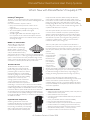
Tranquility 27™
(TT) Series
TWO-STAGE
HORIZONTAL, VERTIC AL, AND DOWNFLOW
EARTHPURE ® SYSTEMS SIZES 026 - 072 [7.0 - 19.3 kW]
Tranquility 27™ (TT) Series
Table of Contents
TT
50
What’s New With The Tranquility 27™? ...............................51
Dimensions — Vertical Downflow .........................................74
Design Features ...................................................................................52
Dimensions — Horizontal ...........................................................76
Unit Model Key....................................................................................54
Electrical Data.......................................................................................78
About AHRI/ISO/ASHRAE 13256-1.......................................55
Standard Electrical Wiring Diagrams .......................................79
AHRI/ISO/ASHRAE/ANSI 13256-1 Performance...........56
ECM Control Features ....................................................................81
Reference Calculations & Legend .............................................57
Blower Performance Data .............................................................83
Full Load Correction Factors .......................................................58
Auxiliary Electric Heat .....................................................................84
Part Load Correction Factors .....................................................59
Auxiliary Heat Ratings .....................................................................84
Performance Data ..............................................................................60
Auxiliary Heat Electrical Data .....................................................84
Performance Data Selection Notes .........................................70
Engineering Guide Specifications...............................................85
Physical Data .........................................................................................71
Accessories, Options, and Warranty........................................86
Dimensions — Vertical Upflow ................................................72
Revision History ..................................................................................88
ClimateMaster : Smar t. Responsible. Comfor table.
ClimateMaster Geothermal Heat Pump Systems
What's New with ClimateMaster's Tranquility 27™?
EarthPure® Refrigerant
EarthPure® is a non-chlorine based (HFC-410A) refrigerant, that
with R-407C and R-134A, is seen as the future of all refrigerants used
worldwide.
HFC 410A characteristics compared to R-22 are:
• Binary and near azeotropic mixture of 50% R-32 and
50% R-125.
• Higher efficiencies (50-60% higher operating pressures)
• Zero ozone depletion potential and low global
warming potential.
• Virtually no glide. Unlike other alternative refrigerants, the
two components in HFC 410A have virtually the same leak
rates. Therefore, refrigerant can be added if necessary without
recovering the charge.
MERV 11 2” Pleated filter
All Tranquility 27™ units include
a factory installed 2” filter rack/
duct collar with a 2” pleated high
efficiency MERV 11 air filter. The
MERV (minimum efficiency reporting
value per ASHRAE Standard 52.2)
design features ultra low velocity (<300 fpm) for extended filter life,
low pressure drop (0.13 – 0.18 in. wg.) and high particulate efficiency
(size E1=41%, E2=69% and E3=87%). The pleated design and low
velocity combine to allow the filter to store a large amount of dirt
and result in a practical replacement life of up to 6 months.
ME
RV
11
E-Coated Air Coil
All ClimateMaster Tranquility 27™ Series
models feature an e-coated air-coil. This
electro-coating process will provide years of
protection against corrosion from airborne
chemicals resulting from modern building
material out gassing and most environmental
chemicals found in the air. Modern building
materials such as counter-tops, floor
coverings, paints and other materials can
“outgas” chemicals into the home’s air.
Some of these chemicals are suspected of
contributing to corrosion in the air coils found in both traditional
and geothermal heating and cooling equipment. Corrosion often
results in refrigerant leaks and eventual failure of the air coil costing
hundreds of dollars to replace. Studies have also shown that these
air coil coatings improve moisture shedding and therefore improve
a unit’s moisture removal capability resulting in a more comfortable
home. The Tranquility27™ Series is your assurance of both maximum
air coil life and comfort.
Copeland Scroll Compressor
Achieve a greater level of comfort. The
Copeland Scroll UltraTech™ provides superior
comfort than fixed-capacity compressors by
incorporating a revolutionary two-step design.
With a unique 67% part-load capacity step,
systems with UltraTech™ maintain precise
temperature levels and lower relative humidity. This eliminates
uneven peaks and valleys and allows for steady cooling comfort.
Homeowners now have a better, more efficient way to power their
heating and cooling system, raising their level of comfort, while
lowering energy bills. So when your customers need a new heating
and cooling system, make sure it has the best technology inside – the
Copeland Scroll UltraTech™ compressor.
Save with superior efficiency. Over 40% of summer utility bills can
come from the air conditioner compressor operation. A system
with the Copeland Scroll UltraTech™ compressor delivers higher
efficiency than any other single compressor system. In fact, systems
with UltraTech™ provide up to 50% greater energy efficiency as
compared to 13-SEER systems – which can save homeowners
hundreds of dollars a year in energy costs.
Take it easy with quieter control. Copeland Scroll UltraTech™ is
remarkably quiet at both full- and part-load capacity. In fact, it is up to
four times quieter than a reciprocating compressor. Homeowners can
enjoy its superior efficiency and comfort without having to hear the
operation.
Learn the beauty
of the design. With
Copeland Scroll
UltraTech™, two
internal bypass
ports enable the
system to run at
67% part-load
capacity for better
efficiency and humidity control. Based on demand, the modulation
ring is activated, sealing the bypass ports and instantly shifting capacity
to 100%. Take advantage of “shift on the fly” stage changing (no
stopping and starting required like other two-stage compressors).
Choose proven scroll performance. While Copeland Scroll
UltraTech™ builds on established scroll technology, it is still a scroll
at heart, which means it operates with fewer moving parts, no
volumetric efficiency drop-off or compression leakage. The result is
unsurpassed reliability and virtually silent operation for both indoor
and outdoor applications.
Other New Features
• Stylish two-tone look with textured black powder coat paint and
stainless steel front access panels.
• Liftout handles for front access panels.
• Corrosion and stain resistant stainless steel drain pan with extra
slope designed in.
• Factory mounted filter drier for trouble free reliability.
• Easy access low profile horizontal control box.
• Double isolated compressor for quiet and vibration free operation.
• Foil faced insulation in air handling compartment to allow easy
cleaning and prevent microfiber introduction into the air stream.
• Open Service-Friendly Cabinet ( i.e, all components in
compressor section can be serviced from the front).
All Products Technical Guide: 2008
TT
51
Tranquility 27™ (TT) Series
Tranquility 27™ Design Features
The Tranquility 27™ Series has abundant features and ultra
high efficiency.
Application Flexibility
• Five Capacities 026, 038, 049, 064, and 072.
• Extended range operation (20-120°F EWT) and flow rates as
low as 1.5 gpm per ton.
• Vertical packages with either true right or true left return
air options.
• Internally trapped condensate drain.
• Variable speed ECM fan motor adapts to various duct systems.
• Internal electric heat unit (optional) designed for easy
field installation.
• Circuit breaker protected loop and hot water generator pumps.
• Field selectable freeze protection setting for well or loop.
• Standard pre-installed 2” filter frame with 2” high performance
MERV 11 pleated air filter.*
Operating Efficiencies
• EarthPure® HFC 410A zero ozone depletion refrigerant.
• Highest efficiencies in AHRI/ISO/ASHRAE/ANSI 13256-1 ratings
for heating COP’s, cooling EER’s with low water flow rates.
• Two-Stage operation for ultra high efficiencies and
unsurpassed comfort.
• Operating temperature range and high efficiency allow
shorter loops.
• Optional hot water generator with internal pump generates hot
water at considerable savings.
• Rugged and highly efficient next generation Copeland
UltraTech™ scroll compressors provide ultra high efficiencies and
full capacity with reduced cycling losses.
• Oversized coaxial tube water-to-refrigerant heat exchangers
operate at low liquid pressure drop. Convoluted copper (and
optional cupronickel) water tube functions efficiently at low-flow
rates and provides freeze-damage resistance.
• Oversized e-coated, rifled tube/lanced aluminum fin, air to
refrigerant heat exchangers provide high efficiency at low
face velocity.
• Large low RPM blowers with variable speed fan motors provide
quiet, efficient air movement with high static capability.
Service Advantages
• Removable panels - 3 for compressor 2 for air
handling compartment.
• Low profile control box grants easy access to all
internal components.
• Factory installed liquid line filter/drier.
• Brass swivel-type water connections for quick connection and
elimination of wrenches or sealants during installation.
• Bi-directional thermal expansion valve.
• CXM control features status lights with memory for
easy diagnostics.
• Unit Performance Sentinel alerts homeowner of potential
performance issues.
• Circuit breaker protected 75VA control transformer.
TT
52
• ECM control board features thermostat signal diagnostic LED’s,
airflow display LED (100 CFM per flash), and simplified CFM
selection.
• Insulated divider and separate air handling/compressor compartments permit service testing without air bypass.
• Fan motors have quick attach wiring harness for fast removal.
• Internal dropout blower for easy servicing.
• High and low pressure service ports on refrigerant circuit.
• Accurate refrigerant sensing freeze protection.
Factory Quality
• All units are built on our Integrated Process Control
Assembly System (IPCS). The IPCS is a unique state of the art
manufacturing system that is designed to assure quality of the
highest standards of any manufacturer in the water-source
industry. Our IPCS system:
- Verifies that the correct components are being assembled.
- Automatically performs special leak tests on all joints.
- Conducts pressure tests.
- Performs highly detailed run test unparalleled in the
HVAC industry.
- Automatically disables packaging for a “failed” unit.
- Creates computer database for future service analysis
an diagnostics from run test results.
• All units are water run-tested in all modes to insure efficiency
and reliability.
• Heavy gauge galvanized steel cabinets are epoxy powder coated
for durable and long-lasting finish.
• All refrigerant brazing is done in a nitrogen atmosphere.
• All units are deep evacuated to less than 100 microns prior to
refrigerant charging.
• All joints are both helium and halogen leak tested to insure
annual leak rate of less than 1/4 ounce.
• Coaxial heat exchanger, refrigerant suction lines and all water
lines are fully insulated to eliminate condensation problems in low
temperature applications.
• Noise Reduction features include: double isolation mounted
compressors; insulated compressor compartment; interior cabinet
insulation using 1/2” coated glass fiber and variable speed fan.
• Safety features include: high pressure and loss of charge to
protect the compressor; condensate overflow protection; freeze
protection sensors to safeguard the coaxial heat exchanger
and air coil; hot water high-limit and low compressor discharge
temperature switch provided to shut down the hot water
generator when conditions dictate. Fault lockout enables
emergency heat and prevents compressor operation until
thermostat or circuit breaker has been reset.
ClimateMaster : Smar t. Responsible. Comfor table.
ClimateMaster Geothermal Heat Pump Systems
Tranquility 27™ Design Features
Simplified Controls
• CXM solid state control module.
• ‘CFM’ LED displays airflow.
• Dehumidification mode for higher latent cooling.
Options & Accessories
• Optional hot water generator with internally mounted pump.
• Optional cupronickel coaxial heat exchanger.
• Electronic thermostat.
• Closed loop Flow Controller.
• Electronic auto-changeover thermostat with 3-stage heat, 2-stage
cool and indicator LED’s.
• Hose kits.
• Optional ClimaDry® Whole House Dehumidification.
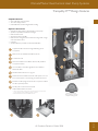
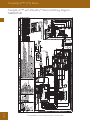
1
Copeland™ Ultra-Tech™ Two-Stage Unloading Scroll
Compressor
2
State-Of-The-Art Variable Speed Blower Motor
3
E-Coated Air Coil
4
Foil Faced Insulation In The Blower Section, Fully Insulated
Compressor Section
5
Two Inch Filter Frame With High Performance MERV 11
Pleated Air Filter*
6
Stainless Steel Drain Pan For Long Life
7
Unit Performance Sentinel: Automatic Alert System Lets You
Know If The System Is Not Running At Peak Performance**
8
Exclusive Double Spring And Grommet Compressor Isolation
For Ultra Quiet Operation
9
Five Easy, Lift-out Service Access Panels
With Stainless Steel Front Panels
5
4
3
6
1
8
* MERV= Minimum Efficiency Reporting Value as specified by ASHRAE (American Society of
Heating, Refrigerating and Air Conditioning Engineers) standard 52.2.
** When installed with a ClimateMaster Residential Thermostat.
8
9
2
7
Features EarthPure®
HFC-410A Zero Ozone
Depletion Refrigerant
7
All Products Technical Guide: 2008
TT
53
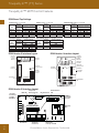
Tranquility 27™ (TT) Series
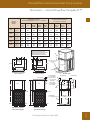
Unit Model Key
1 2
3
4 5 6
7
8
9
10
11
12
13
14
15
TT V 0 2 6 A G C 0 1 A L K S
Series
Standard
TT = Tranquility Two-Stage Scroll
S = Standard
Supply Air Flow &
Motor Configuration
Configuration
V = Vertical Up
H = Horizontal
D = Vertical Down
Supply Configuration
Top
TTV
TTD
Down
TTH
Back
TTH
Straight
K
N
P
W
Unit Size
026, 038, 049, 064, 072
Motor
ECM
ECM
ECM
ECM
Return Air Flow Configuration
Revision Level
L = Left Return
R = Right Return
A = Current Revision
Voltage
Heat Exchanger Options
G = 208-230/60/1
Controls
C = CXM
D = DXM (For Option “D” or “K” in 12th Digit Only)
Cabinet
0 = Residential
Standard
ClimaDry
UniGuard Air Coil
Coated Air Coil
Copper Cupro-Nickel Copper Cupro-Nickel
A
J
B
H
K
N/A
D
N/A
Water Circuit Options
0 = None
1 = HWG w/Internal Pump
Rev.: 22 May, 2009B
TT
54
ClimateMaster : Smar t. Responsible. Comfor table.
ClimateMaster Geothermal Heat Pump Systems
About AHRI/ISO/ASHRAE 13256-1
About AHRI/ISO/ASHRAE 13256-1
AHRI/ASHRAE/ISO 13256-1 (Air-Conditioning and Refrigeration Institute/American Society of Heating, Refrigerating and Air Conditioning
Engineers/International Standards Organization) is a certification standard for water-source heat pumps used in the following applications:
• WLHP (Water Loop Heat Pump – Boiler/Tower)
• GWHP (Ground Water Heat Pump – Open Loop)
• GLHP (Ground Loop Heat Pump – Geothermal)
The directory at http://www.ahrinet.org/ is constantly being updated and immediately available on the Internet. All ratings are submitted by the
manufacturer for certification, and must be approved by AHRI. Therefore, there is a significant difference between AHRI “certified” and AHRI
“rated.” Thirty percent of a manufacturer’s basic models must be tested each year. AHRI selects models at random from stock for testing on
the basis of its evaluation of a participant’s certification data.
Units that fail one or more certified test (90% of declared performance or lower) may be declared defective. If the initial failure is a
performance test, the manufacturer must obsolete all units within the same basic model group or elect to have a second sample tested. If
the second unit fails a performance test, it must be obsoleted, together with all units within the same basic model group. ClimateMaster takes
certification seriously. We were recently awarded a certificate for consecutive years of no AHRI failures.
Temperatures used in AHRI certification standards are S.I. (Système International – metric) based. For example, typical catalog data for cooling
is shown at 80°F DB/67°F WB [26.7°C DB/19.4°C] entering air temperature, but the AHRI standard for cooling is 80.6°F DB/66.2°F WB
[27°C DB/19°C], since it is based upon whole numbers in degrees Celsius. Water and air temperatures for the standard are shown below.
Test Condition Comparison Table
WLHP
GWHP
GLHP
Cooling
Entering Air Temperature - DB/WB °F [°C]
Entering Water Temperature - °F [°C]
Fluid Flow Rate
80.6/66.2 [27/19]
86 [30]
*
80.6/66.2 [27/19]
59 [15]
*
80.6/66.2 [27/19]
77 [25]
*
Heating
Entering Air Temperature - DB/WB °F [°C]
Entering Water Temperature - °F [°C]
Fluid Flow Rate
68 [20]
68 [20]
*
68 [20]
50 [10]
*
68 [20]
32 [0]
*
*Flow rate is specified by the manufacturer
Data certified by AHRI include heating/cooling capacities, EER (Energy Efficiency Ratio – Btuh per Watt) and COP (Btuh per Btuh) at the
various conditions shown above. Pump power correction is calculated to adjust efficiencies for pumping Watts. Within each model, only one
water flow rate is specified for all three groups, and pumping Watts are calculated using the formula below. This additional power is added
onto the existing power consumption.
• Pump power correction = (gpm x 0.0631) x (Press Drop x 2990)/300
Fan power is corrected to zero external static pressure using the equation below. The nominal airflow is rated at a specific external static
pressure. This effectively reduces the power consumption of the unit and increases cooling capacity but decreases heating capacity.
• Fan Power Correction = (cfm x 0.472) x (esp x 249)/300
Capacities and efficiencies are calculated using the following equations:
• ISO Cooling Capacity = Cooling Capacity (Btuh) + [Fan Power Correction (Watts) x 3.412]
• ISO EER Efficiency (Btuh/W) =
ISO Cooling Capacity (Btuh)/[Power Input (Watts) – Fan Power Correction (Watts) + Pump Power Correction (Watts)]
• ISO Heating Capacity = Heating Capacity (Btuh) – [Fan Power Correction (Watts) x 3.412]
• ISO COP Efficiency (Btuh/Btuh) =
ISO Heating Capacity (Btuh) x 3.412/[Power Input (Watts) - Fan Power Correction (Watts) + Pump Power Correction (Watts)]
All Products Technical Guide: 2008
TT
55
Tranquility 27™ (TT) Series
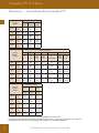
AHRI/ISO/ASHRAE/ANSI 13256-1 Performance
ASHRAE/AHRI/ISO 13256-1. English (IP) Units
Water Loop Heat Pump
Model
Capacity
Modulation
Cooling 86°F
Capacity
Btuh
026
038
049
064
072
EER
Btuh/W
Ground Water Heat Pump
Heating 68°F
Capacity
Btuh
COP
Cooling 59°F
Capacity
Btuh
EER
Btuh/W
Ground Loop Heat Pump
Heating 50°F
Capacity
Btuh
COP
Cooling
Full Load 77°F
Part Load 68°F
Capacity
Btuh
EER
Btuh/W
Heating
Full Load 32°F
Part Load 41°F
Capacity
Btuh
COP
Full
25,300
15.9
30,800
5.3
28,900
24.5
25,700
4.8
26,600
18.5
19,800
4.0
Part
19,400
18.3
22,400
6.1
22,200
30.8
18,600
5.1
21,300
26.0
16,500
4.6
Full
36,200
15.6
44,800
5.3
41,200
23.0
36,700
4.7
38,200
18.2
29,000
4.0
Part
26,200
18.5
30,800
6.3
30,200
31.5
24,800
5.1
28,900
27.0
22,100
4.5
Full
48,400
15.7
59,900
5.2
54,600
22.5
48,300
4.7
50,600
17.9
37,500
4.0
Part
36,100
18.0
44,300
6.2
40,700
28.7
35,400
5.1
39,600
24.9
31,200
4.6
Full
61,500
15.0
72,300
5.0
68,600
22.0
59,600
4.4
64,800
17.5
48,000
3.9
Part
44,900
17.6
51,100
5.7
51,900
29.7
41,800
4.7
49,800
25.3
37,500
4.3
Full
68,700
14.2
88,600
4.9
77,100
19.9
70,200
4.3
71,600
16.2
54,100
3.6
Part
52,800
16.0
65,200
5.1
59,800
24.5
51,700
4.3
57,700
21.4
45,400
3.9
Cooling capacities based upon 80.6°F DB, 66.2°F WB entering air temperature
Heating capacities based upon 68°F DB, 59°F WB entering air temperature
Ground Loop Heat Pump ratings based on 15% methanol antifreeze solution
All ratings based upon operation at lower voltage of dual voltage rated models
ASHRAE/AHRI/ISO 13256-1. Metric (SI) Units
Water Loop Heat Pump
Model
026
038
049
064
072
Capacity
Modulation
Cooling 30°C
Ground Water Heat Pump
Heating 20°C
Cooling 15°C
Ground Loop Heat Pump
Heating 10°C
Cooling
Full Load 25°C
Part Load 20°C
Capacity
Watts
EER
W/W
Capacity
Watts
COP
Capacity
Watts
EER
W/W
Capacity
Watts
COP
Capacity
Watts
EER
W/W
Capacity
Watts
COP
7,415
4.7
9,027
5.3
8,470
7.2
7,532
4.8
7,796
5.4
5,803
4.0
Part
5,686
5.4
6,565
6.1
6,506
9.0
5,451
5.1
6,243
7.6
4,836
4.6
Full
10,610
4.6
13,130
5.3
12,075
6.7
10,756
4.7
11,196
5.3
8,499
4.0
Part
7,679
5.4
9,027
6.3
8,851
9.2
7,268
5.1
8,470
7.9
6,477
4.5
Full
14,185
4.6
17,556
5.2
16,002
6.6
14,156
4.7
14,830
5.2
10,991
4.0
Part
10,580
5.3
12,984
6.2
11,928
8.4
10,375
5.1
11,606
7.3
9,144
4.6
Full
18,025
4.4
21,190
5.0
20,106
6.4
17,468
4.4
18,992
5.1
14,068
3.9
Part
13,159
5.2
14,977
5.7
15,211
8.7
12,251
4.7
14,596
7.4
10,991
4.3
Full
Full
20,135
4.2
25,967
4.9
22,597
5.8
20,574
4.3
20,985
4.7
15,856
3.6
Part
15,475
4.7
19,109
5.1
17,526
7.2
15,152
4.3
16,911
6.3
13,306
3.9
Cooling capacities based upon 27°C DB, 19°C WB entering air temperature
Heating capacities based upon 20°C DB, 15°C WB entering air temperature
Ground Loop Heat Pump ratings based on 15% methanol antifreeze solution
All ratings based upon operation at lower voltage of dual voltage rated models
TT
56
Heating
Full Load 0°C
Part Load 5°C
ClimateMaster : Smar t. Responsible. Comfor table.
ClimateMaster Geothermal Heat Pump Systems
Reference Calculations & Legend
Heating
HE
LWT = EWT GPM x 500
LAT = EAT +
HC
CFM x1.08
Cooling
HR
LWT = EWT +
GPM x 500
LAT (DB) = EAT (DB) -
LC = TC - SC
SC
CFM x1.08
S/T =
SC
TC
Hot Water Generator capacities (HWC) are based on potable water flow rate of 0.4 gpm per nominal
equipment ton and 90°F entering potable water temperature.
CFM
EWT
GPM
EAT
HC
TC
SC
KW
HR
=
=
=
=
=
=
=
=
=
airflow, cubic feet/minute
entering water temperature, ˚F
water flow in US gallons/minute
entering air temperature, Fahrenheit (dry bulb/wet bulb)
air heating capacity, Mbtuh
total cooling capacity, Mbtuh
sensible cooling capacity, Mbtuh
total power unit input, KiloWatts
total heat of rejection, Mbtuh
HE
HWC
WPD
EER
COP
LWT
LAT
LC
S/T
=
=
=
=
=
=
=
=
=
total heat of extraction, Mbtuh
Hot Water Generator (desuperheater) capacity, Mbtuh
Water coil pressure drop (psi & ft hd)
Energy Efficiency Ratio = BTU output/Watt input
Coefficient of Performance = BTU output/BTU input
leaving water temperature, °F
leaving air temperature, °F
latent cooling capacity, Mbtuh
sensible to total cooling ratio
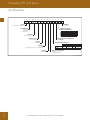
UPFLOW
LEFT RETURN AIR
Piping End
Piping End
Left Return Air
Piping End
Left Return Air
Back Discharge
Piping End
Left Return Air
Side Discharge
Right Return Air
RIGHT RETURN AIR
Piping End
Right Return Air
Back Discharge
All Products Technical Guide: 2008
Piping End
Right Return Air
Side Discharge
Piping End
TT
57
Tranquility 27™ (TT) Series
Full Load Correction Factors
Air Flow Correction Table
Airflow
Cooling
Heating
% of
Rated
Total
Capacity
Sensible
Capacity
Power
Heat of
Rejection
Heating
Capacity
Power
Heat of
Extraction
60%
0.925
0.788
0.913
0.922
0.946
1.153
0.896
69%
0.946
0.829
0.926
0.942
0.959
1.107
0.924
75%
0.960
0.861
0.937
0.955
0.969
1.078
0.942
81%
0.972
0.895
0.950
0.968
0.977
1.053
0.959
88%
0.983
0.930
0.965
0.979
0.985
1.032
0.974
94%
0.992
0.965
0.982
0.990
0.993
1.014
0.988
100%
1.000
1.000
1.000
1.000
1.000
1.000
1.000
106%
1.007
1.033
1.020
1.009
1.006
0.989
1.011
113%
1.012
1.064
1.042
1.018
1.012
0.982
1.019
119%
1.016
1.092
1.066
1.025
1.018
0.979
1.027
125%
1.018
1.116
1.091
1.032
1.022
0.977
1.033
130%
1.019
1.132
1.112
1.037
1.026
0.975
1.038
Entering Air Correction Table
Heating
Entering
Air DB°F
Heating
Capacity
Power
Heat of
Extraction
40
1.052
0.779
1.120
45
1.043
0.808
1.102
50
1.035
0.841
1.084
55
1.027
0.877
1.065
60
1.019
0.915
1.045
65
1.010
0.957
1.023
68
1.004
0.982
1.010
70
1.000
1.000
1.000
75
0.989
1.045
0.974
80
0.976
1.093
0.946
* = Sensible capacity equals total capacity
AHRI/ISO/ASHRAE 13256-1 uses entering air conditions of Cooling - 80.6°F DB/66.2°F WB,
and Heating - 68°F DB/59°F WB entering air temperature
Cooling
TT
58
Entering
Air
WB°F
Total
Capacity
Sensible Cooling Capacity Multiplier Entering DB °F
60
65
70
75
80
80.6
85
90
95
100
Power
Heat of
Rejection
45
0.832
1.346
1.461
1.603
*
*
*
*
*
*
*
0.946
0.853
50
0.850
1.004
1.174
1.357
*
*
*
*
*
*
*
0.953
0.870
55
0.880
0.694
0.902
1.115
1.331
*
*
*
*
*
*
0.964
0.896
60
0.922
0.646
0.875
1.103
1.329
1.356
*
*
*
*
0.977
0.932
65
0.975
0.639
0.869
1.096
1.123
1.320
*
*
*
0.993
0.979
66.2
0.990
0.582
0.812
1.039
1.066
1.262
1.482
*
*
0.997
0.991
67
1.000
0.545
0.774
1.000
1.027
1.223
1.444
*
*
1.000
1.000
70
1.040
0.630
0.853
0.880
1.075
1.297
1.517
*
1.011
1.035
75
1.117
0.601
0.627
0.821
1.046
1.275
1.510
1.033
1.101
ClimateMaster : Smar t. Responsible. Comfor table.
ClimateMaster Geothermal Heat Pump Systems
Part Load Correction Factors
Air Flow Correction Table
Airflow
Cooling
Heating
% of
Rated
Total
Capacity
Sensible
Capacity
Power
Heat of
Rejection
Heating
Capacity
Power
Heat of
Extraction
60%
0.920
0.781
0.959
0.927
0.946
1.241
0.881
69%
0.942
0.832
0.964
0.946
0.960
1.163
0.915
75%
0.956
0.867
0.696
0.959
0.969
1.115
0.937
81%
0.969
0.901
0.975
0.970
0.978
1.076
0.956
88%
0.981
0.934
0.982
0.981
0.986
1.043
0.973
94%
0.991
0.967
0.990
0.991
0.993
1.018
0.988
100%
1.000
1.000
1.000
1.000
1.000
1.000
1.000
106%
1.007
1.033
1.011
1.008
1.006
0.990
1.010
113%
1.013
1.065
1.023
1.015
1.012
0.986
1.017
119%
1.018
1.098
1.036
1.021
1.017
0.983
1.024
125%
1.021
1.131
1.051
1.026
1.021
0.981
1.030
130%
1.023
1.159
1.063
1.030
1.024
0.979
1.034
Entering Air Correction Table
Heating
Entering
Air DB°F
Heating
Capacity
Power
Heat of
Extraction
40
1.084
0.732
1.161
45
1.073
0.764
1.140
50
1.060
0.802
1.117
55
1.046
0.846
1.090
60
1.031
0.893
1.061
65
1.016
0.945
1.031
68
1.006
0.978
1.013
70
1.000
1.000
1.000
75
0.984
1.058
0.968
80
0.968
1.117
0.936
* = Sensible capacity equals total capacity
AHRI/ISO/ASHRAE 13256-1 uses entering air conditions of Cooling - 80.6°F DB/66.2°F WB,
and Heating - 68°F DB/59°F WB entering air temperature
Cooling
Entering
Air
WB°F
Total
Capacity
Sensible Cooling Capacity Multiplier Entering DB °F
60
65
70
75
80
80.6
85
90
95
100
Power
Heat of
Rejection
45
0.876
1.286
1.302
1.389
*
*
*
*
*
*
*
0.981
0.895
50
0.883
1.002
1.099
1.241
*
*
*
*
*
*
*
0.985
0.901
55
0.903
0.706
0.871
1.060
1.271
*
*
*
*
*
*
0.989
0.918
60
0.935
0.617
0.844
1.079
1.319
1.349
*
*
*
*
0.993
0.945
65
0.979
0.595
0.849
1.096
1.128
1.342
*
*
*
0.998
0.982
66.2
0.991
0.531
0.789
1.040
1.070
1.284
1.522
*
*
0.999
0.993
67
1.000
0.486
0.747
1.000
1.030
1.245
1.481
*
*
1.000
1.000
70
1.035
0.583
0.842
0.873
1.090
1.327
1.552
*
1.003
1.030
75
1.105
0.552
0.584
0.811
1.057
1.290
1.510
1.008
1.088
All Products Technical Guide: 2008
TT
59
Tranquility 27™ (TT) Series
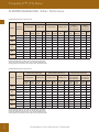
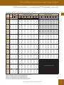
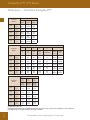
Performance Data — Tranquility 27™ Model 026 - Part Load
725 CFM Nominal (Rated) Airflow Cooling, 825 CFM Nominal (Rated) Airflow Heating
EWT
°F
20
30
40
50
60
70
80
85
90
100
110
120
GPM
7.0
7.0
3.5
3.5
5.8
5.8
7.0
7.0
3.5
3.5
5.8
5.8
7.0
7.0
3.5
3.5
5.8
5.8
7.0
7.0
3.5
3.5
5.8
5.8
7.0
7.0
3.5
3.5
5.8
5.8
7.0
7.0
3.5
3.5
5.8
5.8
7.0
7.0
3.5
3.5
5.8
5.8
7.0
7.0
3.5
3.5
5.8
5.8
7.0
7.0
3.5
3.5
5.8
5.8
7.0
7.0
3.5
3.5
5.8
5.8
7.0
7.0
3.5
3.5
5.8
5.8
7.0
7.0
WPD
Performance capacities shown in thousands of Btuh
Cooling - EAT 80/67°F
PSI
FT
Airflow
CFM
4.5
4.5
1.2
1.2
2.9
2.9
4.1
4.1
1.1
1.1
2.6
2.6
3.6
3.6
1.0
1.0
2.4
2.4
3.4
3.4
1.0
1.0
2.3
2.3
3.2
3.2
0.9
0.9
2.1
2.1
3.0
3.0
0.8
0.8
2.0
2.0
2.8
2.8
0.8
0.8
1.9
1.9
2.7
2.7
0.8
0.8
1.9
1.9
2.7
2.7
0.8
0.8
1.8
1.8
2.6
2.6
0.7
0.7
1.7
1.7
2.5
2.5
0.7
0.7
1.7
1.7
2.4
2.4
10.3
10.3
2.8
2.8
6.6
6.6
9.4
9.4
2.5
2.5
5.9
5.9
8.4
8.4
2.3
2.3
5.6
5.6
7.9
7.9
2.2
2.2
5.2
5.2
7.4
7.4
2.1
2.1
4.9
4.9
7.0
7.0
1.9
1.9
4.6
4.6
6.5
6.5
1.9
1.9
4.5
4.5
6.3
6.3
1.8
1.8
4.4
4.4
6.2
6.2
1.8
1.8
4.2
4.2
6.0
6.0
1.7
1.7
4.0
4.0
5.7
5.7
1.6
1.6
3.9
3.9
5.5
5.5
0
0
620
725
620
725
620
725
620
725
620
725
620
725
620
725
620
725
620
725
620
725
620
725
620
725
620
725
620
725
620
725
620
725
620
725
620
725
620
725
620
725
620
725
620
725
620
725
620
725
620
725
620
725
620
725
620
725
620
725
620
725
620
725
620
725
620
725
TC
SC
kW
HR
0
0
0
0
Operation not recommended
0
0
0
0
22.2
14.0
0.58
24.1
22.5
14.7
0.59
24.4
22.4
14.0
0.57
24.3
22.7
14.7
0.58
24.7
22.5
14.0
0.56
24.4
22.8
14.7
0.57
24.7
22.9
15.1
0.65
25.1
23.3
15.8
0.66
25.5
23.1
15.1
0.61
25.2
23.4
15.9
0.62
25.5
23.2
15.1
0.60
25.2
23.5
15.9
0.61
25.6
22.7
15.4
0.74
25.2
23.0
16.2
0.75
25.6
22.9
15.5
0.69
25.3
23.3
16.3
0.70
25.6
23.0
15.5
0.67
25.3
23.3
16.3
0.68
25.6
21.9
15.3
0.85
24.8
22.2
16.1
0.86
25.1
22.4
15.5
0.78
25.1
22.7
16.3
0.80
25.4
22.5
15.5
0.77
25.1
22.9
16.3
0.78
25.5
20.7
14.8
0.97
24.0
21.0
15.6
0.98
24.3
21.4
15.1
0.90
24.4
21.7
15.9
0.91
24.8
21.6
15.2
0.88
24.6
21.9
16.0
0.89
24.9
19.3
14.2
1.10
23.1
19.6
14.9
1.12
23.4
20.1
14.5
1.03
23.6
20.4
15.3
1.04
23.9
20.3
14.6
1.01
23.7
20.6
15.4
1.02
24.0
18.7
13.9
1.18
22.7
18.9
14.6
1.19
23.0
19.3
14.2
1.10
23.1
19.6
14.9
1.12
23.4
19.5
14.3
1.08
23.2
19.8
15.0
1.10
23.6
18.0
13.7
1.25
22.3
18.3
14.4
1.27
22.6
18.6
13.8
1.18
22.6
18.9
14.6
1.20
22.9
18.8
13.9
1.16
22.7
19.1
14.7
1.17
23.1
16.6
13.0
1.41
21.4
16.8
13.7
1.43
21.7
17.1
13.2
1.34
21.7
17.4
13.8
1.36
22.0
17.3
13.3
1.32
21.8
17.5
13.9
1.34
22.1
15.5
12.7
1.59
20.9
15.7
13.4
1.61
21.2
15.8
12.7
1.53
21.0
16.0
13.3
1.55
21.3
16.0
12.7
1.50
21.1
16.2
13.4
1.52
21.4
14.5
12.6
1.84
20.8
14.7
13.3
1.86
21.1
14.8
12.5
1.73
20.7
15.0
13.2
1.76
21.0
14.9
12.5
1.71
20.7
15.1
13.2
1.73
21.0
Heating - EAT 70°F
EER
HW
Airflow
CFM
HC
0
0
38.3
38.3
39.2
39.2
39.8
39.8
35.3
35.3
37.9
37.9
38.3
38.3
30.7
30.7
33.4
33.4
34.1
34.1
25.9
25.9
28.6
28.6
29.4
29.4
21.4
21.4
23.8
23.8
24.5
24.5
17.5
17.5
19.5
19.5
20.1
20.1
15.9
15.9
17.5
17.5
18.0
18.0
14.4
14.4
15.8
15.8
16.3
16.3
11.7
11.7
12.7
12.7
13.1
13.1
9.7
9.7
10.3
10.3
10.6
10.6
7.9
7.9
8.6
8.6
8.7
8.7
71
710
825
710
825
710
825
710
825
710
825
710
825
710
825
710
825
710
825
710
825
710
825
710
825
710
825
710
825
710
825
710
825
710
825
710
825
710
825
710
825
710
825
710
825
710
825
710
825
710
825
0
0
0
0
0
0
0
0
0
0
0
0
0
0
0
0
0
0
11.6
11.7
13.6
13.8
14.2
14.4
14.4
14.6
16.1
16.2
16.7
16.9
16.9
17.1
18.3
18.5
19.1
19.3
19.3
19.5
20.4
20.6
21.2
21.5
21.5
21.7
22.4
22.7
23.3
23.5
23.5
23.8
24.4
24.6
25.3
25.6
25.6
25.9
25.3
25.6
26.3
26.6
26.6
26.9
26.3
26.6
27.3
27.6
27.6
27.9
0
0
0
0
0
0
0
0
0
0
0
0
0
0
0
0
0
0
0.5
0.5
0.4
0.5
0.4
0.4
0.7
0.7
0.7
0.7
0.6
0.6
1.1
1.1
1.0
1.0
0.9
0.9
2.2
2.2
2.0
2.0
1.7
1.8
1.9
2.0
1.8
1.8
1.6
1.6
2.5
2.5
2.3
2.3
2.1
2.2
2.9
3.0
2.7
2.8
2.5
2.6
3.3
3.4
3.1
3.1
2.8
2.9
3.9
4.0
3.7
3.8
3.6
3.7
5.0
5.1
4.8
4.9
4.6
4.7
6.3
6.4
6.0
6.2
5.8
5.9
kW
Interpolation is permissible; extrapolation is not.
All entering air conditions are 80°F DB and 67°F WB in cooling, and 70°F DB in heating.
AHRI/ISO certified conditions are 80.6°F DB and 66.2°F WB in cooling and 68°F DB in heating.
Table does not reflect fan or pump power corrections for AHRI/ISO conditions.
All performance is based upon the lower voltage of dual voltage rated units.
Operation below 40°F EWT is based upon a 15% methanol antifreeze solution.
Operation below 60°F EWT requires optional insulated water/refrigerant circuit.
See performance correction tables for operating conditions other than those listed above.
For operation in the shaded areas, please see the Performance Data Selection Notes.
TT
60
HE
LAT
COP
1.05
8.2
85.1
3.25
1.02
8.4
83.2
3.38
1.09
10.1
87.8
3.66
1.06
10.3
85.5
3.81
1.09
10.7
88.5
3.81
1.06
10.9
86.1
3.97
1.09
10.9
88.8
3.86
1.06
11.1
86.3
4.02
1.15
12.3
90.9
4.08
1.12
12.6
88.2
4.25
1.15
13.0
91.8
4.25
1.12
13.3
89.0
4.42
1.16
13.2
92.1
4.30
1.12
13.5
89.2
4.47
1.18
14.5
93.9
4.56
1.14
14.8
90.8
4.75
1.18
15.2
94.8
4.73
1.15
15.5
91.6
4.93
1.18
15.4
95.1
4.78
1.15
15.7
91.9
4.98
1.21
16.5
96.6
4.93
1.18
16.8
93.2
5.13
1.22
17.3
97.7
5.10
1.18
17.6
94.1
5.31
1.22
17.5
98.0
5.15
1.19
17.8
94.3
5.36
1.23
18.4
99.2
5.35
1.19
18.8
95.4
5.57
1.24
19.3
100.4
5.52
1.20
19.6
96.4
5.75
1.24
19.5
100.7
5.57
1.20
19.9
96.7
5.80
1.25
20.3
101.8
5.73
1.21
20.7
97.7
5.97
1.26
21.2
103.0
5.90
1.22
21.6
98.7
6.15
1.26
21.5
103.4
5.95
1.22
21.9
99.0
6.20
1.26
21.2
103.0
5.91
1.22
21.7
98.7
6.15
1.27
22.2
104.3
6.08
1.23
22.6
99.9
6.33
1.27
22.5
104.7
6.13
1.24
22.9
100.2
6.38
1.27
22.2
104.3
6.08
1.23
22.6
99.8
6.33
1.28
23.1
105.6
6.25
1.24
23.6
101.0
6.51
1.28
23.4
106.0
6.30
1.25
23.9
101.3
6.56
0
0
0
0
0
0
0
0
0
0
0
0
0
0
0
0
0
0
0
0
0
0
0
0
0
0
0
0
0
0
0
0
0
0 recommended
0
0
Operation
not
0
0
0
0
0
0
0
0
0
0
0
0
0
0
0
0
0
0
0
0
0
0
0
0
0
0
0
0
0
0
0
0
0
0
0
0
ClimateMaster : Smar t. Responsible. Comfor table.
HW
1.4
1.5
1.6
1.6
1.6
1.7
1.7
1.7
1.7
1.7
1.8
1.8
1.8
1.8
1.8
1.8
1.9
1.9
1.9
2.0
2.0
2.0
2.1
2.1
2.1
2.2
2.2
2.2
2.2
2.3
2.3
2.4
2.3
2.3
2.4
2.4
2.5
2.5
2.4
2.4
2.5
2.5
2.6
2.6
2.5
2.5
2.5
2.6
2.6
2.7
ClimateMaster Geothermal Heat Pump Systems
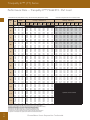
Performance Data — Tranquility 27™ Model 026 - Full Load
850 CFM Nominal (Rated) Airflow Cooling, 950 CFM Nominal (Rated) Airflow Heating
EWT
°F
20
30
40
50
60
70
80
85
90
100
110
120
GPM
8.0
8.0
4.0
4.0
6.0
6.0
8.0
8.0
4.0
4.0
6.0
6.0
8.0
8.0
4.0
4.0
6.0
6.0
8.0
8.0
4.0
4.0
6.0
6.0
8.0
8.0
4.0
4.0
6.0
6.0
8.0
8.0
4.0
4.0
6.0
6.0
8.0
8.0
4.0
4.0
6.0
6.0
8.0
8.0
4.0
4.0
6.0
6.0
8.0
8.0
4.0
4.0
6.0
6.0
8.0
8.0
4.0
4.0
6.0
6.0
8.0
8.0
4.0
4.0
6.0
6.0
8.0
8.0
WPD
Performance capacities shown in thousands of Btuh
Cooling - EAT 80/67°F
PSI
FT
Airflow
CFM
5.6
5.6
1.5
1.5
3.1
3.1
5.1
5.1
1.4
1.4
2.8
2.8
4.6
4.6
1.3
1.3
2.6
2.6
4.3
4.3
1.2
1.2
2.5
2.5
4.0
4.0
1.1
1.1
2.3
2.3
3.8
3.8
1.0
1.0
2.2
2.2
3.5
3.5
1.0
1.0
2.1
2.1
3.4
3.4
1.0
1.0
2.1
2.1
3.4
3.4
1.0
1.0
2.0
2.0
3.2
3.2
0.9
0.9
1.9
1.9
3.1
3.1
0.9
0.9
1.8
1.8
3.0
3.0
12.9
12.9
3.5
3.5
7.2
7.2
11.7
11.7
3.1
3.1
6.5
6.5
10.5
10.5
2.9
2.9
6.1
6.1
9.9
9.9
2.8
2.8
5.7
5.7
9.3
9.3
2.6
2.6
5.4
5.4
8.7
8.7
2.4
2.4
5.0
5.0
8.1
8.1
2.4
2.4
4.9
4.9
7.9
7.9
2.3
2.3
4.8
4.8
7.8
7.8
2.2
2.2
4.6
4.6
7.4
7.4
2.1
2.1
4.4
4.4
7.2
7.2
2.0
2.0
4.2
4.2
6.9
6.9
0
0
730
850
730
850
730
850
730
850
730
850
730
850
730
850
730
850
730
850
730
850
730
850
730
850
730
850
730
850
730
850
730
850
730
850
730
850
730
850
730
850
730
850
730
850
730
850
730
850
730
850
730
850
730
850
730
850
730
850
730
850
730
850
730
850
730
850
TC
SC
kW
HR
0
0
0
0
Operation not recommended
0
0
0
0
30.2
17.9
0.97
33.4
30.9
19.6
1.02
34.3
30.3
17.9
0.93
33.4
31.1
19.6
0.97
34.4
30.5
17.9
0.91
33.5
31.2
19.6
0.95
34.5
29.9
18.2
1.07
33.5
30.6
20.0
1.11
34.4
30.2
18.3
1.01
33.6
30.9
20.0
1.06
34.5
30.3
18.3
0.99
33.6
31.0
20.0
1.03
34.5
29.1
18.3
1.17
33.1
29.8
20.0
1.23
34.0
29.6
18.4
1.11
33.4
30.3
20.1
1.16
34.3
29.9
18.4
1.08
33.5
30.6
20.2
1.13
34.4
28.0
17.9
1.30
32.4
28.6
19.6
1.35
33.3
28.7
18.1
1.23
32.8
29.3
19.9
1.28
33.7
29.0
18.2
1.19
33.0
29.7
20.0
1.24
33.9
26.6
17.3
1.43
31.4
27.2
19.0
1.50
32.3
27.4
17.7
1.36
31.9
28.0
19.4
1.42
32.8
27.7
17.8
1.32
32.2
28.4
19.5
1.38
33.1
25.0
16.6
1.59
30.4
25.6
18.3
1.66
31.2
25.8
17.0
1.50
30.9
26.4
18.7
1.57
31.8
26.3
17.2
1.46
31.2
26.9
18.9
1.53
32.1
24.2
16.3
1.68
29.9
24.7
17.8
1.75
30.7
25.0
16.7
1.59
30.4
25.6
18.3
1.66
31.3
25.4
16.8
1.55
30.7
26.0
18.5
1.61
31.5
23.3
15.9
1.77
29.4
23.9
17.4
1.84
30.2
24.2
16.3
1.67
29.9
24.7
17.9
1.75
30.7
24.6
16.5
1.63
30.2
25.2
18.1
1.70
31.0
21.7
15.2
1.97
28.4
22.2
16.7
2.05
29.2
22.5
15.5
1.86
28.9
23.0
17.0
1.95
29.7
22.9
15.7
1.81
29.1
23.4
17.2
1.89
29.9
20.1
14.6
2.19
27.7
20.6
16.0
2.29
28.4
20.9
14.8
2.08
28.0
21.3
16.3
2.17
28.8
21.2
15.0
2.03
28.2
21.7
16.4
2.11
29.0
18.8
14.1
2.45
27.2
19.2
15.5
2.55
28.0
19.4
14.3
2.32
27.4
19.8
15.7
2.43
28.2
19.7
14.4
2.26
27.5
20.2
15.8
2.36
28.3
Heating - EAT 70°F
EER
0
0
31.0
30.4
32.7
32.1
33.7
33.1
28.1
27.5
29.8
29.2
30.7
30.1
24.8
24.3
26.7
26.1
27.6
27.0
21.6
21.2
23.4
22.9
24.3
23.8
18.5
18.2
20.2
19.8
21.0
20.6
15.7
15.4
17.2
16.8
17.9
17.6
14.4
14.1
15.7
15.4
16.5
16.1
13.2
13.0
14.4
14.2
15.1
14.8
11.0
10.8
12.1
11.8
12.6
12.4
9.2
9.0
10.0
9.8
10.5
10.3
7.7
7.5
8.3
8.2
8.7
8.5
HW
Airflow
CFM
0.6
0.6
0.5
0.6
0.5
0.5
1.0
1.0
0.9
0.9
0.8
0.9
1.6
1.6
1.4
1.5
1.3
1.3
2.2
2.2
2.0
2.0
1.7
1.8
2.9
3.0
2.6
2.7
2.3
2.4
3.5
3.6
3.2
3.3
3.0
3.0
3.9
4.0
3.6
3.7
3.3
3.4
4.5
4.6
4.1
4.2
3.8
3.9
4.9
5.0
4.7
4.8
4.5
4.6
5.8
6.0
5.6
5.8
5.4
5.5
6.9
7.1
6.7
6.8
6.4
6.5
820
950
820
950
820
950
820
950
820
950
820
950
820
950
820
950
820
950
820
950
820
950
820
950
820
950
820
950
820
950
820
950
820
950
820
950
820
950
820
950
820
950
820
950
820
950
820
950
820
950
0
0
0
0
0
0
0
0
0
0
0
0
0
0
0
0
0
0
HC
kW
HE
LAT
COP
15.0
1.47
10.2
86.9
3.00
15.3
1.41
10.6
84.9
3.19
17.8
1.53
12.7
90.1
3.41
18.1
1.46
13.2
87.7
3.63
18.6
1.54
13.5
91.0
3.53
19.0
1.48
14.0
88.5
3.76
19.1
1.55
13.9
91.5
3.59
19.4
1.49
14.4
88.9
3.82
21.2
1.61
15.9
94.0
3.88
21.6
1.54
16.4
91.1
4.12
22.2
1.63
16.7
95.0
3.99
22.6
1.56
17.3
92.0
4.24
22.7
1.64
17.2
95.6
4.05
23.1
1.57
17.8
92.5
4.31
24.4
1.69
18.7
97.5
4.24
24.9
1.62
19.4
94.2
4.51
25.4
1.71
19.6
98.7
4.34
25.9
1.64
20.3
95.2
4.62
25.9
1.73
20.1
99.3
4.40
26.4
1.66
20.8
95.7
4.68
27.2
1.77
21.3
100.8
4.52
27.8
1.69
22.0
97.1
4.81
28.3
1.8
22.2
101.9
4.62
28.8
1.72
23.0
98.1
4.91
28.8
1.81
22.7
102.6
4.66
29.4
1.74
23.5
98.6
4.96
29.9
1.84
23.6
103.7
4.75
30.5
1.77
24.4
99.7
5.05
31.0
1.88
24.6
105.0
4.83
31.6
1.80
25.4
100.8
5.14
31.5
1.90
25.1
105.6
4.87
32.1
1.82
25.9
101.3
5.18
32.3
1.92
25.8
106.5
4.93
33.0
1.84
26.7
102.1
5.24
33.5
1.96
26.8
107.8
5.01
34.1
1.88
27.7
103.2
5.32
34.0
1.98
27.3
108.4
5.04
34.7
1.90
28.2
103.8
5.36
33.5
1.96
26.8
107.9
5.01
34.2
1.88
27.8
103.3
5.33
34.7
2.00
27.8
109.1
5.08
35.3
1.92
28.8
104.4
5.40
35.2
2.02
28.4
109.8
5.12
35.9
1.93
29.3
105.0
5.44
34.7
2.00
27.9
109.2
5.09
35.4
1.92
28.8
104.5
5.41
35.9
2.04
28.9
110.5
5.16
36.6
1.95
29.9
105.6
5.48
36.5
2.06
29.4
111.2
5.19
37.2
1.97
30.4
106.2
5.52
0
0
0
0
0
0
0
0
0
0
0
0
0
0
0
0
0
0
0
0
0
0
0
0
0
0
0
0
0
0
0
0
0
0
0
0
0
0
0
0
0 Operation
0
0 recommended
0
0
not
0
0
0
0
0
0
0
0
0
0
0
0
0
0
0
0
0
0
0
0
0
0
0
0
0
0
0
0
0
0
0
0
0
0
0
0
0
0
0
0
0
0
0
0
0
HW
1.7
1.7
2.0
2.0
2.1
2.1
2.1
2.2
2.3
2.3
2.4
2.4
2.5
2.5
2.6
2.7
2.7
2.8
2.8
2.9
2.9
3.0
3.1
3.1
3.2
3.2
3.3
3.3
3.4
3.5
3.5
3.6
3.6
3.6
3.7
3.8
3.9
3.9
3.7
3.8
3.9
3.9
4.0
4.1
3.9
3.9
4.0
4.1
4.2
4.3
Interpolation is permissible; extrapolation is not.
All entering air conditions are 80°F DB and 67°F WB in cooling, and 70°F DB in heating.
AHRI/ISO certified conditions are 80.6°F DB and 66.2°F WB in cooling and 68°F DB in heating.
Table does not reflect fan or pump power corrections for AHRI/ISO conditions.
All performance is based upon the lower voltage of dual voltage rated units.
Operation below 40°F EWT is based upon a 15% methanol antifreeze solution.
Operation below 60°F EWT requires optional insulated water/refrigerant circuit.
See performance correction tables for operating conditions other than those listed above.
For operation in the shaded areas, please see the Performance Data Selection Notes.
All Products Technical Guide: 2008
TT
61
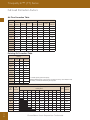
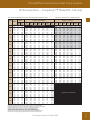
Tranquility 27™ (TT) Series
Performance Data — Tranquility 27™ Model 038 - Part Load
1000 CFM Nominal (Rated) Airflow Cooling, 1000 CFM Nominal (Rated) Airflow Heating
EWT
°F
20
30
40
50
60
70
80
85
90
100
110
120
GPM
8.0
8.0
4.0
4.0
6.0
6.0
8.0
8.0
4.0
4.0
6.0
6.0
8.0
8.0
4.0
4.0
6.0
6.0
8.0
8.0
4.0
4.0
6.0
6.0
8.0
8.0
4.0
4.0
6.0
6.0
8.0
8.0
4.0
4.0
6.0
6.0
8.0
8.0
4.0
4.0
6.0
6.0
8.0
8.0
4.0
4.0
6.0
6.0
8.0
8.0
4.0
4.0
6.0
6.0
8.0
8.0
4.0
4.0
6.0
6.0
8.0
8.0
4.0
4.0
6.0
6.0
8.0
8.0
WPD
Performance capacities shown in thousands of Btuh
Cooling - EAT 80/67°F
PSI
FT
Airflow
CFM
4.7
4.7
1.2
1.2
2.6
2.6
4.5
4.5
1.1
1.1
2.6
2.6
4.4
4.4
1.0
1.0
2.5
2.5
4.2
4.2
0.9
0.9
2.4
2.4
4.1
4.1
0.8
0.8
2.3
2.3
4.0
4.0
0.7
0.7
2.3
2.3
3.9
3.9
0.7
0.7
2.2
2.2
3.8
3.8
0.7
0.7
2.1
2.1
3.7
3.7
0.6
0.6
2.1
2.1
3.6
3.6
0.6
0.6
2.0
2.0
3.4
3.4
0.5
0.5
1.9
1.9
3.3
3.3
10.9
10.9
2.8
2.8
6.1
6.1
10.4
10.4
2.5
2.5
5.9
5.9
10.2
10.2
2.2
2.2
5.7
5.7
9.7
9.7
2.0
2.0
5.5
5.5
9.5
9.5
1.8
1.8
5.3
5.3
9.2
9.2
1.7
1.7
5.2
5.2
9.0
9.0
1.6
1.6
5.1
5.1
8.8
8.8
1.5
1.5
4.9
4.9
8.5
8.5
1.4
1.4
4.8
4.8
8.3
8.3
1.3
1.3
4.6
4.6
7.9
7.9
1.2
1.2
4.5
4.5
7.7
7.7
0
0
860
1000
860
1000
860
1000
860
1000
860
1000
860
1000
860
1000
860
1000
860
1000
860
1000
860
1000
860
1000
860
1000
860
1000
860
1000
860
1000
860
1000
860
1000
860
1000
860
1000
860
1000
860
1000
860
1000
860
1000
860
1000
860
1000
860
1000
860
1000
860
1000
860
1000
860
1000
860
1000
860
1000
TC
SC
kW
HR
0
0
0
0
Operation not recommended
0
0
0
0
30.4
19.2
0.79
33.0
30.8
20.2
0.80
33.5
30.7
19.2
0.75
33.2
31.1
20.2
0.76
33.6
30.9
19.3
0.73
33.3
31.3
20.3
0.74
33.8
31.1
20.8
0.90
34.1
31.6
21.8
0.91
34.6
31.3
20.8
0.84
34.2
31.8
21.9
0.85
34.6
31.5
20.8
0.81
34.2
32.0
21.9
0.82
34.7
30.9
21.4
1.04
34.4
31.3
22.5
1.05
34.8
31.2
21.6
0.96
34.4
31.7
22.7
0.97
34.9
31.4
21.6
0.92
34.5
31.8
22.7
0.93
35.0
29.7
21.5
1.19
33.8
30.2
22.6
1.21
34.2
30.4
21.7
1.10
34.2
30.9
22.8
1.11
34.6
30.7
21.7
1.06
34.3
31.2
22.8
1.07
34.8
28.2
20.9
1.37
32.8
28.6
22.0
1.39
33.3
29.1
21.3
1.27
33.4
29.5
22.4
1.28
33.8
29.5
21.4
1.22
33.6
29.9
22.5
1.23
34.1
26.4
20.1
1.56
31.7
26.8
21.2
1.59
32.2
27.4
20.6
1.45
32.3
27.8
21.6
1.47
32.8
27.9
20.8
1.40
32.6
28.3
21.8
1.42
33.1
25.5
19.7
1.67
31.2
25.9
20.8
1.70
31.7
26.5
20.2
1.56
31.8
26.9
21.2
1.58
32.2
27.0
20.4
1.50
32.1
27.4
21.4
1.53
32.5
24.7
19.3
1.79
30.7
25.0
20.3
1.81
31.2
25.6
19.7
1.67
31.2
25.9
20.8
1.69
31.7
26.1
20.0
1.61
31.5
26.4
21.0
1.63
32.0
23.1
18.8
2.03
30.0
23.4
19.7
2.06
30.4
23.8
19.0
1.90
30.3
24.2
20.0
1.93
30.8
24.3
19.2
1.84
30.5
24.6
20.2
1.87
31.0
21.9
18.6
2.30
29.7
22.2
19.6
2.34
30.2
22.4
18.6
2.16
29.8
22.7
19.6
2.19
30.2
22.7
18.7
2.10
29.9
23.0
19.6
2.13
30.3
21.0
18.2
2.58
29.9
21.3
19.2
2.61
30.3
21.5
18.6
2.45
29.9
21.8
19.6
2.49
30.3
21.7
18.7
2.41
29.9
22.0
19.7
2.45
30.3
Heating - EAT 70°F
EER
0
0
38.3
38.3
40.9
40.9
42.2
42.2
34.5
34.5
37.3
37.3
38.8
38.8
29.8
29.8
32.6
32.6
34.1
34.1
25.0
25.0
27.7
27.7
29.1
29.1
20.6
20.6
23.0
23.0
24.3
24.3
16.9
16.9
18.8
18.8
19.9
19.9
15.3
15.3
17.0
17.0
17.9
17.9
13.8
13.8
15.3
15.3
16.2
16.2
11.4
11.4
12.5
12.5
13.2
13.2
9.5
9.5
10.4
10.4
10.8
10.8
8.2
8.2
8.8
8.8
9.0
9.0
HW
Airflow
CFM
0.5
0.5
0.5
0.5
0.4
0.5
0.8
0.8
0.7
0.7
0.7
0.7
1.2
1.2
1.1
1.1
1.0
1.0
2.5
2.6
2.3
2.3
2.0
2.0
2.2
2.3
2.0
2.1
1.8
1.8
2.8
2.9
2.6
2.7
2.4
2.5
3.4
3.5
3.1
3.2
2.9
3.0
3.8
3.9
3.6
3.6
3.3
3.4
4.5
4.6
4.4
4.4
4.2
4.3
5.8
5.9
5.6
5.7
5.4
5.5
7.3
7.5
7.0
7.2
6.8
6.9
860
1000
860
1000
860
1000
860
1000
860
1000
860
1000
860
1000
860
1000
860
1000
860
1000
860
1000
860
1000
860
1000
860
1000
860
1000
860
1000
860
1000
860
1000
860
1000
860
1000
860
1000
860
1000
860
1000
860
1000
860
1000
0
0
0
0
0
0
0
0
0
0
0
0
0
0
0
0
0
0
HC
kW
Interpolation is permissible; extrapolation is not.
All entering air conditions are 80°F DB and 67°F WB in cooling, and 70°F DB in heating.
AHRI/ISO certified conditions are 80.6°F DB and 66.2°F WB in cooling and 68°F DB in heating.
Table does not reflect fan or pump power corrections for AHRI/ISO conditions.
All performance is based upon the lower voltage of dual voltage rated units.
Operation below 40°F EWT is based upon a 15% methanol antifreeze solution.
Operation below 60°F EWT requires optional insulated water/refrigerant circuit.
See performance correction tables for operating conditions other than those listed above.
For operation in the shaded areas, please see the Performance Data Selection Notes.
TT
62
HE
LAT
COP
17.5
1.60
12.4
88.9
3.21
17.7
1.55
12.6
86.4
3.34
19.3
1.61
14.1
90.8
3.52
19.5
1.56
14.4
88.1
3.67
20.0
1.61
14.8
91.5
3.64
20.2
1.56
15.1
88.7
3.79
20.4
1.61
15.2
91.9
3.70
20.6
1.57
15.5
89.1
3.85
22.0
1.62
16.8
93.7
3.98
22.3
1.57
17.1
90.6
4.15
22.9
1.63
17.6
94.6
4.12
23.1
1.58
18.0
91.4
4.30
23.3
1.63
18.1
95.1
4.20
23.6
1.58
18.4
91.9
4.37
24.9
1.64
19.6
96.8
4.45
25.2
1.59
20.0
93.3
4.64
25.9
1.64
20.6
97.9
4.62
26.2
1.60
21.0
94.3
4.81
26.5
1.65
21.1
98.5
4.70
26.8
1.60
21.5
94.8
4.89
27.8
1.66
22.5
100.0
4.93
28.1
1.61
22.9
96.1
5.13
29.0
1.66
23.7
101.3
5.12
29.4
1.62
24.1
97.2
5.33
29.7
1.67
24.3
102.0
5.22
30.0
1.62
24.8
97.8
5.44
30.9
1.68
25.4
103.2
5.40
31.2
1.63
25.9
98.9
5.63
32.3
1.68
26.8
104.8
5.62
32.7
1.64
27.4
100.3
5.85
33.1
1.69
27.6
105.6
5.74
33.5
1.64
28.1
101.0
5.98
34.0
1.70
28.5
106.7
5.88
34.4
1.65
29.1
101.9
6.13
35.7
1.71
30.2
108.4
6.13
36.1
1.66
30.7
103.4
6.38
36.6
1.71
31.0
109.4
6.27
37.0
1.66
31.7
104.3
6.53
35.7
1.71
30.1
108.4
6.13
36.1
1.66
30.7
103.4
6.38
37.5
1.72
31.9
110.3
6.39
37.9
1.67
32.5
105.1
6.66
38.5
1.73
32.8
111.4
6.54
38.9
1.67
33.5
106.0
6.81
37.3
1.72
31.7
110.2
6.37
37.7
1.67
32.3
104.9
6.63
39.2
1.73
33.6
112.2
6.65
39.7
1.68
34.2
106.7
6.92
40.3
1.74
34.6
113.4
6.80
40.8
1.69
35.3
107.7
7.08
0
0
0
0
0
0
0
0
0
0
0
0
0
0
0
0
0
0
0
0
0
0
0
0
0
0
0
0
0
0
0
0
0
0
0
0
0
0
0
0
0
0
0 recommended
0
0
Operation
not
0
0
0
0
0
0
0
0
0
0
0
0
0
0
0
0
0
0
0
0
0
0
0
0
0
0
0
0
0
0
0
0
0
0
0
0
0
0
0
0
0
0
0
0
0
ClimateMaster : Smar t. Responsible. Comfor table.
HW
1.9
1.9
2.1
2.1
2.2
2.2
2.3
2.3
2.3
2.3
2.4
2.4
2.5
2.5
2.4
2.5
2.5
2.6
2.6
2.6
2.7
2.7
2.8
2.8
2.9
2.9
2.9
3.0
3.1
3.1
3.2
3.2
3.2
3.2
3.3
3.3
3.4
3.4
3.3
3.3
3.4
3.4
3.5
3.6
3.4
3.4
3.5
3.5
3.6
3.7
ClimateMaster Geothermal Heat Pump Systems
Performance Data — Tranquility 27™ Model 038 - Full Load
1250 CFM Nominal (Rated) Airflow Cooling, 1250 CFM Nominal (Rated) Airflow Heating
EWT
°F
20
30
40
50
60
70
80
85
90
100
110
120
GPM
9.0
9.0
4.5
4.5
6.8
6.8
9.0
9.0
4.5
4.5
6.8
6.8
9.0
9.0
4.5
4.5
6.8
6.8
9.0
9.0
4.5
4.5
6.8
6.8
9.0
9.0
4.5
4.5
6.8
6.8
9.0
9.0
4.5
4.5
6.8
6.8
9.0
9.0
4.5
4.5
6.8
6.8
9.0
9.0
4.5
4.5
6.8
6.8
9.0
9.0
4.5
4.5
6.8
6.8
9.0
9.0
4.5
4.5
6.8
6.8
9.0
9.0
4.5
4.5
6.8
6.8
9.0
9.0
WPD
Performance capacities shown in thousands of Btuh
Cooling - EAT 80/67°F
PSI
FT
Airflow
CFM
5.9
5.9
1.7
1.7
3.3
3.3
5.7
5.7
1.5
1.5
3.2
3.2
5.4
5.4
1.3
1.3
3.1
3.1
5.2
5.2
1.2
1.2
3.0
3.0
5.0
5.0
1.1
1.1
2.9
2.9
4.8
4.8
1.0
1.0
2.8
2.8
4.5
4.5
1.0
1.0
2.8
2.8
4.5
4.5
0.9
0.9
2.7
2.7
4.4
4.4
0.8
0.8
2.6
2.6
4.2
4.2
0.8
0.8
2.5
2.5
4.0
4.0
0.7
0.7
2.5
2.5
3.8
3.8
13.7
13.7
3.9
3.9
7.7
7.7
13.1
13.1
3.5
3.5
7.4
7.4
12.5
12.5
3.1
3.1
7.2
7.2
12.0
12.0
2.8
2.8
6.9
6.9
11.6
11.6
2.5
2.5
6.7
6.7
11.0
11.0
2.3
2.3
6.6
6.6
10.4
10.4
2.2
2.2
6.4
6.4
10.3
10.3
2.1
2.1
6.2
6.2
10.2
10.2
1.9
1.9
6.1
6.1
9.7
9.7
1.8
1.8
5.9
5.9
9.2
9.2
1.6
1.6
5.9
5.9
8.8
8.8
0
0
1080
1250
1080
1250
1080
1250
1080
1250
1080
1250
1080
1250
1080
1250
1080
1250
1080
1250
1080
1250
1080
1250
1080
1250
1080
1250
1080
1250
1080
1250
1080
1250
1080
1250
1080
1250
1080
1250
1080
1250
1080
1250
1080
1250
1080
1250
1080
1250
1080
1250
1080
1250
1080
1250
1080
1250
1080
1250
1080
1250
1080
1250
1080
1250
1080
1250
TC
SC
kW
HR
0
0
0
0
Operation not recommended
0
0
0
0
43.1
27.4
1.55
48.3
44.1
30.1
1.61
49.6
43.3
27.5
1.44
48.1
44.3
30.1
1.51
49.4
43.4
27.5
1.39
48.1
44.4
30.1
1.45
49.4
42.3
27.5
1.69
48.0
43.3
30.1
1.77
49.4
42.9
27.6
1.59
48.2
43.9
30.2
1.66
49.6
43.1
27.6
1.53
48.3
44.1
30.3
1.60
49.6
41.1
27.1
1.85
47.4
42.1
29.7
1.93
48.7
42.0
27.4
1.74
47.9
43.0
30.0
1.81
49.2
42.4
27.5
1.68
48.1
43.4
30.1
1.75
49.4
39.6
26.4
2.02
46.4
40.5
29.0
2.11
47.7
40.7
26.9
1.90
47.1
41.7
29.5
1.98
48.4
41.2
27.1
1.84
47.4
42.2
29.7
1.92
48.7
37.8
25.7
2.22
45.3
38.7
28.2
2.32
46.6
39.1
26.2
2.08
46.1
40.0
28.8
2.17
47.4
39.7
26.5
2.01
46.5
40.6
29.0
2.10
47.8
35.8
24.8
2.44
44.2
36.7
27.2
2.55
45.4
37.2
25.4
2.29
45.0
38.0
27.9
2.39
46.2
37.8
25.7
2.21
45.4
38.7
28.2
2.31
46.6
34.8
24.3
2.57
43.6
35.6
26.7
2.68
44.8
36.2
25.0
2.40
44.4
37.0
27.4
2.51
45.6
36.8
25.3
2.33
44.8
37.7
27.7
2.43
46.0
33.8
23.9
2.70
43.0
34.6
26.2
2.81
44.2
35.1
24.5
2.52
43.8
36.0
26.9
2.63
45.0
35.8
24.8
2.44
44.2
36.7
27.2
2.55
45.4
31.8
22.9
2.99
42.0
32.5
25.2
3.12
43.2
33.1
23.5
2.80
42.6
33.8
25.8
2.92
43.8
33.7
23.9
2.70
43.0
34.5
26.2
2.82
44.2
29.8
22.1
3.34
41.3
30.5
24.2
3.49
42.4
31.0
22.6
3.12
41.7
31.7
24.8
3.25
42.9
31.7
22.9
3.01
42.0
32.4
25.1
3.14
43.1
28.0
21.3
3.74
40.9
28.7
23.3
3.91
42.0
29.1
21.7
3.49
41.1
29.8
23.8
3.64
42.2
29.7
22.0
3.36
41.2
30.4
24.1
3.51
42.4
Heating - EAT 70°F
EER
HW
Airflow
CFM
0
0
27.9
27.3
30.0
29.4
31.2
30.6
25.0
24.5
27.1
26.5
28.1
27.6
22.2
21.8
24.2
23.7
25.2
24.8
19.6
19.2
21.4
21.0
22.4
22.0
17.0
16.7
18.8
18.4
19.7
19.3
14.7
14.4
16.3
15.9
17.1
16.8
13.6
13.3
15.0
14.7
15.8
15.5
12.5
12.3
13.9
13.7
14.7
14.4
10.6
10.4
11.8
11.6
12.5
12.2
8.9
8.7
10.0
9.8
10.5
10.3
7.5
7.3
8.3
8.2
8.8
8.6
0
0
0.6
0.6
0.6
0.6
0.6
0.6
1.1
1.1
1.0
1.1
0.9
1.0
1.8
1.8
1.6
1.7
1.5
1.5
2.5
2.6
2.3
2.3
2.0
2.0
3.4
3.5
3.0
3.1
2.7
2.7
4.0
4.1
3.7
3.8
3.4
3.5
4.5
4.6
4.2
4.3
3.9
3.9
5.2
5.3
4.8
4.9
4.4
4.5
5.7
5.8
5.5
5.6
5.3
5.4
6.8
7.0
6.6
6.7
6.3
6.5
8.1
8.2
7.8
7.9
7.5
7.6
1080
1250
1080
1250
1080
1250
1080
1250
1080
1250
1080
1250
1080
1250
1080
1250
1080
1250
1080
1250
1080
1250
1080
1250
1080
1250
1080
1250
1080
1250
1080
1250
1080
1250
1080
1250
1080
1250
1080
1250
1080
1250
1080
1250
1080
1250
1080
1250
1080
1250
0
0
0
0
0
0
0
0
0
0
0
0
0
0
0
0
0
0
HC
kW
HE
LAT
COP
25.7
2.28
18.2
92.0
3.30
26.2
2.18
18.8
89.4
3.51
27.9
2.32
20.2
93.9
3.52
28.4
2.22
20.9
91.1
3.75
29.2
2.35
21.4
95.0
3.64
29.7
2.25
22.1
92.0
3.87
29.9
2.36
22.0
95.6
3.71
30.4
2.26
22.8
92.5
3.94
31.8
2.40
23.8
97.2
3.88
32.4
2.30
24.6
94.0
4.12
33.3
2.44
25.2
98.6
4.01
33.9
2.34
26.0
95.1
4.26
34.1
2.46
25.9
99.3
4.08
34.8
2.35
26.8
95.8
4.33
35.7
2.49
27.4
100.6
4.20
36.4
2.39
28.3
97.0
4.47
37.5
2.54
29.0
102.2
4.34
38.3
2.43
30.0
98.3
4.61
38.5
2.56
29.9
103.0
4.41
39.3
2.46
30.9
99.1
4.68
39.8
2.60
31.0
104.1
4.50
40.6
2.49
32.1
100.1
4.78
41.9
2.65
32.9
105.9
4.63
42.7
2.54
34.1
101.6
4.92
43.1
2.69
34.0
106.9
4.70
43.9
2.58
35.1
102.5
5.00
44.0
2.71
34.8
107.7
4.75
44.8
2.60
36.0
103.2
5.05
46.4
2.79
36.9
109.8
4.88
47.3
2.67
38.2
105.0
5.19
47.8
2.83
38.2
111.0
4.95
48.7
2.71
39.5
106.1
5.27
48.3
2.84
38.6
111.4
4.98
49.2
2.73
39.9
106.5
5.29
51.1
2.93
41.1
113.8
5.10
52.1
2.81
42.5
108.6
5.43
52.7
2.99
42.4
115.1
5.17
53.7
2.86
43.9
109.8
5.50
50.5
2.92
40.6
113.3
5.08
51.5
2.80
41.9
108.1
5.40
53.5
3.02
43.2
115.9
5.20
54.5
2.89
44.7
110.4
5.53
55.2
3.07
44.7
117.3
5.26
56.3
2.95
46.2
111.7
5.59
52.7
2.99
42.5
115.2
5.17
53.7
2.86
44.0
109.8
5.50
55.9
3.10
45.3
117.9
5.29
57.0
2.97
46.9
112.2
5.62
57.7
3.16
46.9
119.5
5.35
58.8
3.03
48.5
113.6
5.69
0
0
0
0
0
0
0
0
0
0
0
0
0
0
0
0
0
0
0
0
0
0
0
0
0
0
0
0
0
0
0
0
0
0
0
0
0
0
0
0
0 Operation
0
0 recommended
0
0
not
0
0
0
0
0
0
0
0
0
0
0
0
0
0
0
0
0
0
0
0
0
0
0
0
0
0
0
0
0
0
0
0
0
0
0
0
0
0
0
0
0
0
0
0
0
HW
2.2
2.3
2.7
2.8
2.8
2.9
2.9
3.0
3.1
3.2
3.3
3.3
3.4
3.4
3.6
3.6
3.7
3.8
3.9
3.9
4.1
4.1
4.2
4.3
4.4
4.4
4.5
4.6
4.7
4.8
4.9
5.0
5.0
5.0
5.2
5.2
5.4
5.4
5.2
5.3
5.4
5.5
5.6
5.7
5.4
5.5
5.6
5.7
5.8
5.9
Interpolation is permissible; extrapolation is not.
All entering air conditions are 80°F DB and 67°F WB in cooling, and 70°F DB in heating.
AHRI/ISO certified conditions are 80.6°F DB and 66.2°F WB in cooling and 68°F DB in heating.
Table does not reflect fan or pump power corrections for AHRI/ISO conditions.
All performance is based upon the lower voltage of dual voltage rated units.
Operation below 40°F EWT is based upon a 15% methanol antifreeze solution.
Operation below 60°F EWT requires optional insulated water/refrigerant circuit.
See performance correction tables for operating conditions other than those listed above.
For operation in the shaded areas, please see the Performance Data Selection Notes.
All Products Technical Guide: 2008
TT
63
Tranquility 27™ (TT) Series
Performance Data — Tranquility 27™ Model 049 - Part Load
1300 CFM Nominal (Rated) Airflow Cooling, 1400 CFM Nominal (Rated) Airflow Heating
EWT
°F
20
30
40
50
60
70
80
85
90
100
110
120
GPM
11.0
11.0
5.5
5.5
8.3
8.3
11.0
11.0
5.5
5.5
8.3
8.3
11.0
11.0
5.5
5.5
8.3
8.3
11.0
11.0
5.5
5.5
8.3
8.3
11.0
11.0
5.5
5.5
8.3
8.3
11.0
11.0
5.5
5.5
8.3
8.3
11.0
11.0
5.5
5.5
8.3
8.3
11.0
11.0
5.5
5.5
8.3
8.3
11.0
11.0
5.5
5.5
8.3
8.3
11.0
11.0
5.5
5.5
8.3
8.3
11.0
11.0
5.5
5.5
8.3
8.3
11.0
11.0
WPD
Performance capacities shown in thousands of Btuh
Cooling - EAT 80/67°F
PSI
FT
Airflow
CFM
4.0
4.0
1.1
1.1
2.3
2.3
3.9
3.9
1.0
1.0
2.2
2.2
3.7
3.7
0.9
0.9
2.1
2.1
3.6
3.6
0.8
0.8
2.0
2.0
3.5
3.5
0.8
0.8
2.0
2.0
3.3
3.3
0.7
0.7
1.9
1.9
3.2
3.2
0.7
0.7
1.9
1.9
3.1
3.1
0.7
0.7
1.8
1.8
3.1
3.1
0.7
0.7
1.8
1.8
3.0
3.0
0.6
0.6
1.7
1.7
2.8
2.8
0.6
0.6
1.7
1.7
2.7
2.7
9.3
9.3
2.5
2.5
5.2
5.2
8.9
8.9
2.3
2.3
5.0
5.0
8.6
8.6
2.1
2.1
4.9
4.9
8.3
8.3
2.0
2.0
4.7
4.7
8.1
8.1
1.8
1.8
4.6
4.6
7.5
7.5
1.7
1.7
4.5
4.5
7.3
7.3
1.7
1.7
4.3
4.3
7.3
7.3
1.6
1.6
4.2
4.2
7.2
7.2
1.5
1.5
4.1
4.1
6.8
6.8
1.5
1.5
4.0
4.0
6.6
6.6
1.4
1.4
3.8
3.8
6.3
6.3
0
0
1120
1300
1120
1300
1120
1300
1120
1300
1120
1300
1120
1300
1120
1300
1120
1300
1120
1300
1120
1300
1120
1300
1120
1300
1120
1300
1120
1300
1120
1300
1120
1300
1120
1300
1120
1300
1120
1300
1120
1300
1120
1300
1120
1300
1120
1300
1120
1300
1120
1300
1120
1300
1120
1300
1120
1300
1120
1300
1120
1300
1120
1300
1120
1300
1120
1300
TC
SC
kW
HR
0
0
0
0
Operation not recommended
0
0
0
0
38.6
24.0
1.20
42.6
39.1
25.2
1.22
43.3
38.8
24.0
1.14
42.6
39.4
25.3
1.15
43.2
39.0
24.0
1.10
42.7
39.6
25.2
1.12
43.3
40.8
26.2
1.37
45.5
41.4
27.6
1.38
46.1
41.2
26.3
1.28
45.5
41.8
27.6
1.30
46.2
41.3
26.3
1.25
45.5
41.9
27.6
1.27
46.1
40.8
26.8
1.49
45.9
41.4
28.2
1.51
46.5
41.2
26.9
1.41
45.9
41.7
28.2
1.43
46.6
41.3
26.9
1.40
46.0
41.9
28.3
1.42
46.7
40.0
27.1
1.73
45.9
40.6
28.5
1.75
46.5
40.7
27.2
1.62
46.2
41.3
28.6
1.64
46.9
41.0
27.2
1.57
46.3
41.5
28.7
1.59
46.9
38.2
26.5
1.94
44.8
38.8
27.9
1.97
45.4
39.3
26.9
1.82
45.5
39.9
28.3
1.85
46.1
39.8
27.1
1.76
45.7
40.3
28.4
1.79
46.4
35.9
25.7
2.17
43.3
36.5
27.0
2.20
43.9
37.2
26.2
2.04
44.2
37.7
27.5
2.07
44.8
37.8
26.4
1.98
44.6
38.4
27.8
2.01
45.2
34.7
25.2
2.30
42.5
35.2
26.5
2.34
43.1
36.0
25.7
2.17
43.4
36.5
27.0
2.20
44.0
36.6
25.9
2.10
43.8
37.1
27.3
2.13
44.4
33.4
24.7
2.44
41.7
33.9
25.9
2.47
42.3
34.7
25.2
2.30
42.6
35.2
26.5
2.33
43.2
35.4
25.5
2.23
43.0
35.9
26.8
2.26
43.6
30.9
23.7
2.73
40.2
31.3
24.9
2.77
40.7
32.1
24.2
2.58
40.9
32.6
25.4
2.62
41.5
32.8
24.4
2.50
41.3
33.3
25.7
2.54
41.9
28.5
22.9
3.07
39.0
28.9
24.1
3.11
39.6
29.6
23.3
2.90
39.5
30.0
24.5
2.94
40.1
30.2
23.5
2.82
39.8
30.6
24.7
2.86
40.4
26.7
22.7
3.45
38.4
27.0
23.8
3.50
39.0
27.5
22.7
3.26
38.6
27.9
23.9
3.31
39.2
27.9
22.8
3.17
38.8
28.3
24.0
3.22
39.3
Heating - EAT 70°F
EER
HW
Airflow
CFM
HC
0
0
32.0
32.0
34.2
34.2
35.4
35.4
29.9
29.9
32.1
32.1
32.9
32.9
27.3
27.3
29.1
29.1
29.4
29.4
23.2
23.2
25.1
25.1
26.1
26.1
19.7
19.7
21.6
21.6
22.6
22.6
16.5
16.5
18.2
18.2
19.1
19.1
15.0
15.0
16.6
16.6
17.4
17.4
13.7
13.7
15.1
15.1
15.9
15.9
11.3
11.3
12.5
12.5
13.1
13.1
9.3
9.3
10.2
10.2
10.7
10.7
7.7
7.7
8.4
8.4
8.8
8.8
0
0
0.6
0.6
0.5
0.6
0.5
0.5
1.0
1.0
0.9
1.0
0.9
0.9
1.6
1.7
1.5
1.5
1.3
1.4
3.5
3.6
3.2
3.2
2.8
2.9
3.1
3.2
2.8
2.9
2.5
2.5
4.0
4.1
3.7
3.8
3.4
3.5
4.8
5.0
4.5
4.6
4.1
4.2
5.5
5.6
5.1
5.2
4.7
4.8
6.5
6.6
6.3
6.4
6.0
6.2
8.4
8.5
8.0
8.2
7.7
7.9
10.6
10.8
10.2
10.4
9.8
10.0
1200
1400
1200
1400
1200
1400
1200
1400
1200
1400
1200
1400
1200
1400
1200
1400
1200
1400
1200
1400
1200
1400
1200
1400
1200
1400
1200
1400
1200
1400
1200
1400
1200
1400
1200
1400
1200
1400
1200
1400
1200
1400
1200
1400
1200
1400
1200
1400
1200
1400
0
0
0
0
0
0
0
0
0
0
0
0
0
0
0
0
0
0
23.2
23.5
25.6
25.9
26.6
26.9
27.1
27.4
29.6
30.0
30.9
31.2
31.6
31.9
34.0
34.4
35.6
36.0
36.5
36.9
38.7
39.1
40.6
41.1
41.7
42.1
43.4
43.9
45.6
46.1
46.8
47.3
48.0
48.6
50.4
50.9
51.6
52.2
50.2
50.8
52.6
53.2
53.8
54.4
52.4
53.0
54.8
55.4
56.0
56.7
0
0
0
0
0
0
0
0
0
0
0
0
0
0
0
0
0
0
kW
Interpolation is permissible; extrapolation is not.
All entering air conditions are 80°F DB and 67°F WB in cooling, and 70°F DB in heating.
AHRI/ISO certified conditions are 80.6°F DB and 66.2°F WB in cooling and 68°F DB in heating.
Table does not reflect fan or pump power corrections for AHRI/ISO conditions.
All performance is based upon the lower voltage of dual voltage rated units.
Operation below 40°F EWT is based upon a 15% methanol antifreeze solution.
Operation below 60°F EWT requires optional insulated water/refrigerant circuit.
See performance correction tables for operating conditions other than those listed above.
For operation in the shaded areas, please see the Performance Data Selection Notes.
TT
64
HE
LAT
COP
2.16
16.2
87.9
3.14
2.10
16.6
85.5
3.27
2.20
18.6
89.8
3.42
2.14
18.9
87.2
3.56
2.21
19.4
90.5
3.52
2.15
19.8
87.8
3.67
2.22
19.9
90.9
3.58
2.15
20.3
88.1
3.73
2.24
22.4
92.9
3.88
2.18
22.9
89.8
4.04
2.25
23.6
93.8
4.02
2.19
24.1
90.7
4.19
2.26
24.3
94.4
4.10
2.19
24.8
91.1
4.27
2.28
26.7
96.3
4.38
2.21
27.2
92.8
4.56
2.29
28.2
97.5
4.56
2.23
28.8
93.8
4.74
2.30
29.1
98.2
4.65
2.23
29.6
94.4
4.85
2.32
31.2
99.8
4.89
2.25
31.8
95.9
5.09
2.33
33.0
101.3
5.10
2.27
33.7
97.2
5.31
2.34
34.1
102.1
5.21
2.27
34.7
97.9
5.43
2.36
35.7
103.5
5.39
2.29
36.4
99.0
5.62
2.38
37.9
105.2
5.62
2.31
38.6
100.5
5.85
2.39
39.0
106.1
5.73
2.32
39.7
101.3
5.97
2.40
40.2
107.1
5.86
2.33
41.0
102.1
6.10
2.43
42.5
108.9
6.07
2.36
43.3
103.7
6.33
2.45
43.7
109.8
6.18
2.38
44.5
104.5
6.44
2.43
42.3
108.8
6.06
2.36
43.1
103.6
6.31
2.46
44.6
110.6
6.26
2.39
45.4
105.2
6.52
2.48
45.7
111.5
6.35
2.41
46.6
106.0
6.62
2.46
44.4
110.5
6.25
2.39
45.3
105.1
6.51
2.50
46.7
112.3
6.44
2.42
47.6
106.7
6.70
2.52
47.8
113.2
6.52
2.45
48.8
107.5
6.79
0
0
0
0
0
0
0
0
0
0
0
0
0
0
0
0
0
0
0
0
0
0
0
0
0
0
0
0
0
0
0
0
0
0 recommended
0
0
Operation
not
0
0
0
0
0
0
0
0
0
0
0
0
0
0
0
0
0
0
0
0
0
0
0
0
0
0
0
0
0
0
0
0
0
0
0
0
ClimateMaster : Smar t. Responsible. Comfor table.
HW
2.3
2.3
2.5
2.5
2.6
2.6
2.7
2.7
2.7
2.8
2.8
2.9
2.9
3.0
2.9
2.9
3.0
3.0
3.1
3.2
3.2
3.3
3.3
3.4
3.5
3.5
3.5
3.6
3.7
3.7
3.8
3.9
3.8
3.8
3.9
4.0
4.1
4.1
3.9
4.0
4.1
4.1
4.2
4.3
4.0
4.1
4.2
4.3
4.4
4.4
ClimateMaster Geothermal Heat Pump Systems
Performance Data — Tranquility 27™ Model 049 - Full Load
1550 CFM Nominal (Rated) Airflow Cooling, 1650 CFM Nominal (Rated) Airflow Heating
EWT
°F
20
30
40
50
60
70
80
85
90
100
110
120
GPM
12.0
12.0
6.0
6.0
9.0
9.0
12.0
12.0
6.0
6.0
9.0
9.0
12.0
12.0
6.0
6.0
9.0
9.0
12.0
12.0
6.0
6.0
9.0
9.0
12.0
12.0
6.0
6.0
9.0
9.0
12.0
12.0
6.0
6.0
9.0
9.0
12.0
12.0
6.0
6.0
9.0
9.0
12.0
12.0
6.0
6.0
9.0
9.0
12.0
12.0
6.0
6.0
9.0
9.0
12.0
12.0
6.0
6.0
9.0
9.0
12.0
12.0
6.0
6.0
9.0
9.0
12.0
12.0
WPD
Performance capacities shown in thousands of Btuh
Cooling - EAT 80/67°F
PSI
FT
Airflow
CFM
4.8
4.8
1.3
1.3
2.7
2.7
4.6
4.6
1.1
1.1
2.6
2.6
4.4
4.4
1.1
1.1
2.5
2.5
4.2
4.2
1.0
1.0
2.4
2.4
4.0
4.0
0.9
0.9
2.3
2.3
3.8
3.8
0.9
0.9
2.3
2.3
3.6
3.6
0.9
0.9
2.2
2.2
3.6
3.6
0.9
0.9
2.2
2.2
3.5
3.5
0.8
0.8
2.1
2.1
3.3
3.3
0.8
0.8
2.0
2.0
3.2
3.2
0.8
0.8
2.0
2.0
3.0
3.0
11.0
11.0
2.9
2.9
6.1
6.1
10.5
10.5
2.7
2.7
5.9
5.9
10.1
10.1
2.5
2.5
5.7
5.7
9.6
9.6
2.3
2.3
5.5
5.5
9.2
9.2
2.2
2.2
5.4
5.4
8.8
8.8
2.1
2.1
5.2
5.2
8.3
8.3
2.0
2.0
5.1
5.1
8.2
8.2
2.0
2.0
5.0
5.0
8.1
8.1
1.9
1.9
4.8
4.8
7.7
7.7
1.8
1.8
4.7
4.7
7.3
7.3
1.7
1.7
4.5
4.5
7.0
7.0
0
0
1330
1550
1330
1550
1330
1550
1330
1550
1330
1550
1330
1550
1330
1550
1330
1550
1330
1550
1330
1550
1330
1550
1330
1550
1330
1550
1330
1550
1330
1550
1330
1550
1330
1550
1330
1550
1330
1550
1330
1550
1330
1550
1330
1550
1330
1550
1330
1550
1330
1550
1330
1550
1330
1550
1330
1550
1330
1550
1330
1550
1330
1550
1330
1550
1330
1550
TC
SC
kW
HR
0
0
0
0
Operation not recommended
0
0
0
0
56.1
32.1
2.13
63.2
57.4
35.1
2.22
65.0
56.5
32.1
2.01
63.2
57.9
35.2
2.09
65.0
56.8
32.1
1.94
63.3
58.2
35.2
2.03
65.1
55.8
33.0
2.32
63.6
57.1
36.2
2.42
65.4
56.4
33.0
2.19
63.7
57.7
36.2
2.28
65.5
56.6
33.0
2.12
63.8
58.0
36.2
2.22
65.5
54.5
33.3
2.51
63.0
55.8
36.5
2.62
64.7
55.6
33.4
2.37
63.6
56.9
36.6
2.47
65.4
56.0
33.4
2.30
63.7
57.3
36.7
2.40
65.5
52.5
32.6
2.71
61.7
53.7
35.8
2.82
63.4
54.0
33.1
2.56
62.7
55.3
36.3
2.67
64.4
54.7
33.3
2.49
63.1
55.9
36.5
2.60
64.8
49.9
31.7
2.93
59.9
51.1
34.8
3.06
61.6
51.7
32.4
2.77
61.1
53.0
35.5
2.89
62.8
52.6
32.7
2.70
61.7
53.8
35.8
2.81
63.4
47.1
30.6
3.18
57.9
48.2
33.6
3.32
59.5
49.0
31.4
3.01
59.3
50.2
34.4
3.14
60.9
50.0
31.7
2.92
59.9
51.2
34.8
3.05
61.6
45.5
30.1
3.32
56.9
46.6
33.0
3.47
58.5
47.5
30.8
3.14
58.2
48.6
33.8
3.28
59.8
48.5
31.2
3.05
58.9
49.6
34.2
3.19
60.5
44.0
29.5
3.47
55.9
45.0
32.4
3.62
57.4
46.0
30.2
3.28
57.2
47.1
33.2
3.42
58.8
47.0
30.6
3.18
57.9
48.1
33.6
3.32
59.5
40.9
28.5
3.80
53.9
41.8
31.2
3.97
55.4
42.8
29.1
3.59
55.1
43.8
31.9
3.74
56.6
43.8
29.4
3.48
55.8
44.9
32.3
3.64
57.3
37.8
27.6
4.19
52.2
38.7
30.2
4.38
53.7
39.6
28.1
3.95
53.2
40.6
30.8
4.12
54.7
40.6
28.4
3.83
53.7
41.5
31.1
4.00
55.2
34.9
27.0
4.65
51.0
35.8
29.6
4.86
52.4
36.6
27.3
4.37
51.6
37.4
29.9
4.57
53.1
37.4
27.5
4.24
52.0
38.3
30.1
4.43
53.5
Heating - EAT 70°F
EER
HW
Airflow
CFM
0
0
26.4
25.9
28.2
27.6
29.3
28.7
24.1
23.6
25.8
25.3
26.7
26.2
21.8
21.3
23.5
23.0
24.3
23.8
19.4
19.0
21.1
20.7
21.9
21.5
17.1
16.7
18.7
18.3
19.5
19.1
14.8
14.5
16.3
16.0
17.1
16.8
13.7
13.4
15.1
14.8
15.9
15.6
12.7
12.4
14.0
13.8
14.8
14.5
10.7
10.5
11.9
11.7
12.6
12.3
9.0
8.8
10.0
9.8
10.6
10.4
7.5
7.4
8.4
8.2
8.8
8.7
0
0
0.8
0.8
0.7
0.7
0.7
0.7
1.5
1.5
1.4
1.4
1.2
1.3
2.5
2.6
2.3
2.3
2.0
2.0
3.5
3.6
3.2
3.2
2.8
2.9
4.8
4.9
4.3
4.4
3.8
3.9
5.8
5.9
5.4
5.5
4.9
5.0
6.5
6.7
6.0
6.2
5.5
5.7
7.5
7.6
6.9
7.1
6.3
6.5
8.2
8.4
7.9
8.1
7.6
7.8
9.9
10.1
9.5
9.7
9.2
9.4
11.7
12.0
11.3
11.5
10.9
11.1
1430
1650
1430
1650
1430
1650
1430
1650
1430
1650
1430
1650
1430
1650
1430
1650
1430
1650
1430
1650
1430
1650
1430
1650
1430
1650
1430
1650
1430
1650
1430
1650
1430
1650
1430
1650
1430
1650
1430
1650
1430
1650
1430
1650
1430
1650
1430
1650
1430
1650
0
0
0
0
0
0
0
0
0
0
0
0
0
0
0
0
0
0
HC
kW
HE
LAT
COP
31.6
2.90
22.1
90.5
3.20
32.3
2.78
22.9
88.1
3.40
34.7
2.98
24.9
92.5
3.41
35.4
2.86
25.7
89.9
3.62
36.3
3.03
26.3
93.5
3.51
37.0
2.90
27.2
90.8
3.73
37.2
3.05
27.0
94.1
3.57
37.9
2.93
28.0
91.3
3.79
40.0
3.13
29.6
95.9
3.75
40.8
3.00
30.6
92.9
3.99
42.0
3.18
31.4
97.2
3.87
42.8
3.05
32.4
94.0
4.11
43.1
3.21
32.4
97.9
3.94
43.9
3.08
33.5
94.6
4.19
45.5
3.27
34.6
99.5
4.08
46.4
3.14
35.8
96.0
4.34
48.0
3.33
36.8
101.1
4.22
48.9
3.20
38.0
97.4
4.48
49.3
3.37
38.0
101.9
4.29
50.3
3.23
39.3
98.2
4.56
51.3
3.42
39.8
103.2
4.39
52.3
3.28
41.1
99.3
4.67
54.2
3.50
42.4
105.1
4.54
55.2
3.36
43.8
101.0
4.83
55.8
3.54
43.8
106.1
4.62
56.9
3.40
45.3
101.9
4.91
57.2
3.58
45.1
107.1
4.68
58.3
3.44
46.6
102.7
4.98
60.6
3.68
48.1
109.2
4.83
61.7
3.53
49.7
104.7
5.13
62.4
3.73
49.7
110.4
4.90
63.6
3.58
51.4
105.7
5.21
63.2
3.76
50.5
111.0
4.94
64.5
3.60
52.2
106.2
5.25
67.0
3.87
53.8
113.4
5.07
68.3
3.71
55.7
108.3
5.39
69.1
3.94
55.7
114.8
5.14
70.5
3.78
57.6
109.5
5.47
66.3
3.85
53.2
112.9
5.04
67.6
3.69
55.0
107.9
5.36
70.3
3.98
56.7
115.5
5.18
71.6
3.82
58.6
110.2
5.50
72.5
4.06
58.6
116.9
5.24
73.9
3.89
60.6
111.5
5.57
69.3
3.95
55.8
114.9
5.15
70.7
3.78
57.7
109.7
5.47
73.5
4.09
59.5
117.6
5.27
74.9
3.92
61.6
112.1
5.60
75.8
4.17
61.5
119.1
5.33
77.3
4.00
63.6
113.4
5.66
0
0
0
0
0
0
0
0
0
0
0
0
0
0
0
0
0
0
0
0
0
0
0
0
0
0
0
0
0
0
0
0
0
0
0
0
0
0
0
0
0 Operation
0
0 recommended
0
0
not
0
0
0
0
0
0
0
0
0
0
0
0
0
0
0
0
0
0
0
0
0
0
0
0
0
0
0
0
0
0
0
0
0
0
0
0
0
0
0
0
0
0
0
0
0
HW
2.7
2.7
3.2
3.3
3.4
3.4
3.5
3.5
3.8
3.8
3.9
4.0
4.1
4.1
4.3
4.4
4.5
4.5
4.6
4.7
4.9
5.0
5.1
5.2
5.3
5.4
5.5
5.6
5.7
5.8
5.9
6.0
6.0
6.1
6.2
6.3
6.5
6.6
6.3
6.4
6.5
6.6
6.8
6.9
6.5
6.6
6.8
6.9
7.1
7.2
Interpolation is permissible; extrapolation is not.
All entering air conditions are 80°F DB and 67°F WB in cooling, and 70°F DB in heating.
AHRI/ISO certified conditions are 80.6°F DB and 66.2°F WB in cooling and 68°F DB in heating.
Table does not reflect fan or pump power corrections for AHRI/ISO conditions.
All performance is based upon the lower voltage of dual voltage rated units.
Operation below 40°F EWT is based upon a 15% methanol antifreeze solution.
Operation below 60°F EWT requires optional insulated water/refrigerant circuit.
See performance correction tables for operating conditions other than those listed above.
For operation in the shaded areas, please see the Performance Data Selection Notes.
All Products Technical Guide: 2008
TT
65
Tranquility 27™ (TT) Series
Performance Data — Tranquility 27™ Model 064 - Part Load
1500 CFM Nominal (Rated) Airflow Cooling, 1650 CFM Nominal (Rated) Airflow Heating
EWT
°F
20
30
40
50
60
70
80
85
90
100
110
120
GPM
14.0
14.0
7.0
7.0
10.5
10.5
14.0
14.0
7.0
7.0
10.5
10.5
14.0
14.0
7.0
7.0
10.5
10.5
14.0
14.0
7.0
7.0
10.5
10.5
14.0
14.0
7.0
7.0
10.5
10.5
14.0
14.0
7.0
7.0
10.5
10.5
14.0
14.0
7.0
7.0
10.5
10.5
14.0
14.0
7.0
7.0
10.5
10.5
14.0
14.0
7.0
7.0
10.5
10.5
14.0
14.0
7.0
7.0
10.5
10.5
14.0
14.0
7.0
7.0
10.5
10.5
14.0
14.0
WPD
Performance capacities shown in thousands of Btuh
Cooling - EAT 80/67°F
PSI
FT
Airflow
CFM
4.1
4.1
0.5
0.5
1.9
1.9
3.9
3.9
0.4
0.4
1.8
1.8
3.7
3.7
0.3
0.3
1.8
1.8
3.6
3.6
0.3
0.3
1.7
1.7
3.4
3.4
0.2
0.2
1.7
1.7
3.3
3.3
0.2
0.2
1.6
1.6
3.1
3.1
0.2
0.2
1.6
1.6
3.0
3.0
0.1
0.1
1.5
1.5
3.0
3.0
0.1
0.1
1.5
1.5
2.8
2.8
0.1
0.1
1.5
1.5
2.7
2.7
0.1
0.1
1.4
1.4
2.6
2.6
9.4
9.4
1.1
1.1
4.4
4.4
9.0
9.0
0.9
0.9
4.3
4.3
8.6
8.6
0.7
0.7
4.1
4.1
8.2
8.2
0.6
0.6
4.0
4.0
7.8
7.8
0.5
0.5
3.9
3.9
7.5
7.5
0.4
0.4
3.8
3.8
7.2
7.2
0.4
0.4
3.7
3.7
7.0
7.0
0.3
0.3
3.6
3.6
6.8
6.8
0.2
0.2
3.5
3.5
6.5
6.5
0.2
0.2
3.3
3.3
6.2
6.2
0.1
0.1
3.2
3.2
6.0
6.0
0
0
1280
1500
1280
1500
1280
1500
1280
1500
1280
1500
1280
1500
1280
1500
1280
1500
1280
1500
1280
1500
1280
1500
1280
1500
1280
1500
1280
1500
1280
1500
1280
1500
1280
1500
1280
1500
1280
1500
1280
1500
1280
1500
1280
1500
1280
1500
1280
1500
1280
1500
1280
1500
1280
1500
1280
1500
1280
1500
1280
1500
1280
1500
1280
1500
1280
1500
TC
SC
kW
HR
0
0
0
Operation
not 0recommended
0
0
0
0
49.1
33.2
1.54
54.2
49.7
35.0
1.56
55.0
50.1
33.6
1.50
55.1
50.8
35.3
1.52
55.9
51.6
34.4
1.48
56.6
52.3
36.2
1.51
57.4
51.9
35.8
1.68
57.6
52.7
37.6
1.71
58.4
52.3
35.8
1.60
57.7
53.1
37.7
1.63
58.5
52.7
35.9
1.57
57.9
53.4
37.7
1.59
58.8
52.0
36.5
1.88
58.4
52.8
38.4
1.91
59.2
52.6
36.5
1.76
58.5
53.3
38.4
1.79
59.3
52.7
36.5
1.71
58.5
53.5
38.4
1.74
59.4
50.2
35.8
2.12
57.3
50.9
37.6
2.15
58.2
51.3
36.2
1.98
58.0
52.0
38.1
2.01
58.8
51.8
36.4
1.91
58.3
52.5
38.3
1.94
59.1
47.5
34.5
2.41
55.7
48.2
36.3
2.44
56.5
49.1
35.2
2.24
56.7
49.7
37.1
2.28
57.5
49.8
35.6
2.17
57.1
50.5
37.4
2.20
57.9
44.5
33.0
2.74
53.8
45.1
34.7
2.78
54.5
46.1
33.8
2.56
54.8
46.8
35.6
2.59
55.6
46.9
34.2
2.47
55.3
47.6
36.0
2.51
56.1
42.8
32.3
2.93
52.8
43.5
34.0
2.97
53.6
44.5
33.1
2.74
53.8
45.1
34.8
2.78
54.6
45.3
33.5
2.65
54.3
46.0
35.2
2.68
55.1
41.2
31.6
3.12
51.8
41.8
33.2
3.16
52.6
42.9
32.3
2.92
52.8
43.5
34.0
2.96
53.6
43.7
32.7
2.82
53.3
44.3
34.4
2.86
54.1
38.1
30.3
3.54
50.2
38.7
31.9
3.59
50.9
39.6
30.9
3.33
51.0
40.2
32.5
3.38
51.7
40.4
31.2
3.22
51.4
41.0
32.8
3.27
52.1
35.5
29.6
4.02
49.3
36.0
31.1
4.08
49.9
36.7
29.8
3.79
49.6
37.2
31.4
3.84
50.3
37.3
30.0
3.67
49.9
37.9
31.6
3.73
50.6
33.7
29.2
4.57
49.3
34.2
30.7
4.63
50.0
34.4
29.3
4.30
49.1
34.9
30.8
4.36
49.8
34.9
29.5
4.18
49.1
35.4
31.0
4.24
49.8
Heating - EAT 70°F
EER
HW
Airflow
CFM
HC
0
0
31.8
31.8
33.4
33.4
34.7
34.7
30.9
30.9
32.7
32.7
33.6
33.6
27.7
27.7
29.8
29.8
30.8
30.8
23.7
23.7
25.9
25.9
27.1
27.1
19.8
19.8
21.9
21.9
23.0
23.0
16.2
16.2
18.0
18.0
19.0
19.0
14.6
14.6
16.2
16.2
17.1
17.1
13.2
13.2
14.7
14.7
15.5
15.5
10.8
10.8
11.9
11.9
12.5
12.5
8.8
8.8
9.7
9.7
10.2
10.2
7.4
7.4
8.0
8.0
8.3
8.3
0
0
0.6
0.6
0.6
0.6
0.5
0.5
1.1
1.1
1.0
1.0
0.9
0.9
1.7
1.8
1.6
1.6
1.4
1.4
3.8
3.8
3.4
3.4
3.0
3.0
3.3
3.4
3.0
3.0
2.6
2.7
4.3
4.4
4.0
4.1
3.7
3.7
5.2
5.3
4.8
4.9
4.4
4.5
5.9
6.0
5.4
5.5
5.0
5.1
6.9
7.1
6.7
6.8
6.4
6.6
8.9
9.1
8.6
8.8
8.3
8.4
11.3
11.5
10.9
11.1
10.5
10.7
1430
1650
1430
1650
1430
1650
1430
1650
1430
1650
1430
1650
1430
1650
1430
1650
1430
1650
1430
1650
1430
1650
1430
1650
1430
1650
1430
1650
1430
1650
1430
1650
1430
1650
1430
1650
1430
1650
1430
1650
1430
1650
1430
1650
1430
1650
1430
1650
1430
1650
0
0
0
0
0
0
0
0
0
0
0
0
0
0
0
0
0
0
28.7
29.0
31.7
32.0
32.7
33.0
33.2
33.6
36.1
36.5
37.4
37.8
38.1
38.5
40.9
41.3
42.4
42.9
43.2
43.7
45.7
46.2
47.5
48.0
48.5
49.0
50.6
51.2
52.6
53.2
53.7
54.3
55.4
56.1
57.6
58.3
58.8
59.5
57.8
58.4
60.0
60.7
61.2
61.9
60.1
60.8
62.4
63.1
63.6
64.3
0
0
0
0
0
0
0
0
0
0
0
0
0
0
0
0
0
0
kW
Interpolation is permissible; extrapolation is not.
All entering air conditions are 80°F DB and 67°F WB in cooling, and 70°F DB in heating.
AHRI/ISO certified conditions are 80.6°F DB and 66.2°F WB in cooling and 68°F DB in heating.
Table does not reflect fan or pump power corrections for AHRI/ISO conditions.
All performance is based upon the lower voltage of dual voltage rated units.
Operation below 40°F EWT is based upon a 15% methanol antifreeze solution.
Operation below 60°F EWT requires optional insulated water/refrigerant circuit.
See performance correction tables for operating conditions other than those listed above.
For operation in the shaded areas, please see the Performance Data Selection Notes.
TT
66
HE
LAT
COP
2.85
19.5
88.6
2.95
2.77
19.9
86.3
3.07
2.87
22.5
90.5
3.24
2.78
22.9
88.0
3.37
2.87
23.4
91.2
3.34
2.79
23.9
88.5
3.47
2.87
24.0
91.5
3.39
2.79
24.4
88.8
3.53
2.89
26.8
93.4
3.67
2.80
27.4
90.5
3.82
2.89
28.1
94.2
3.79
2.81
28.6
91.2
3.95
2.90
28.8
94.7
3.86
2.81
29.3
91.6
4.02
2.91
31.5
96.5
4.11
2.83
32.1
93.2
4.28
2.92
33.0
97.5
4.26
2.83
33.6
94.1
4.43
2.92
33.8
98.0
4.33
2.84
34.4
94.5
4.51
2.94
36.2
99.6
4.55
2.86
36.9
95.9
4.74
2.96
37.9
100.8
4.71
2.87
38.7
97.0
4.91
2.96
38.9
101.4
4.79
2.88
39.6
97.5
4.99
2.98
40.9
102.8
4.97
2.90
41.7
98.7
5.18
3.01
42.9
104.1
5.13
2.92
43.7
99.9
5.35
3.02
43.9
104.8
5.22
2.93
44.8
100.5
5.43
3.04
45.6
105.9
5.35
2.95
46.5
101.5
5.57
3.07
47.7
107.3
5.50
2.98
48.6
102.7
5.73
3.09
48.8
108.1
5.58
3.00
49.7
103.4
5.81
3.08
47.8
107.4
5.51
2.99
48.7
102.8
5.73
3.11
49.9
108.9
5.65
3.02
50.9
104.1
5.88
3.14
51.0
109.6
5.72
3.04
52.0
104.7
5.96
3.11
50.0
108.9
5.66
3.02
51.0
104.1
5.90
3.16
52.1
110.4
5.80
3.06
53.2
105.4
6.04
3.18
53.2
111.2
5.86
3.09
54.3
106.1
6.10
0
0
0
0
0
0
0
0
0
0
0
0
0
0
0
0
0
0
0
0
0
0
0
0
0
0
0
0
0
0
0
0
0
0 recommended
0
0
Operation
not
0
0
0
0
0
0
0
0
0
0
0
0
0
0
0
0
0
0
0
0
0
0
0
0
0
0
0
0
0
0
0
0
0
0
0
0
ClimateMaster : Smar t. Responsible. Comfor table.
HW
2.4
2.5
2.7
2.7
2.8
2.8
2.9
2.9
2.9
3.0
3.0
3.1
3.1
3.2
3.1
3.1
3.2
3.3
3.3
3.4
3.4
3.5
3.6
3.6
3.7
3.8
3.8
3.8
3.9
4.0
4.1
4.1
4.1
4.1
4.2
4.3
4.4
4.4
4.2
4.3
4.4
4.4
4.5
4.6
4.3
4.4
4.5
4.6
4.7
4.8
ClimateMaster Geothermal Heat Pump Systems
Performance Data — Tranquility 27™ Model 064 - Full Load
1825 CFM Nominal (Rated) Airflow Cooling, 2050 CFM Nominal (Rated) Airflow Heating
EWT
°F
20
30
40
50
60
70
80
85
90
100
110
120
GPM
15.0
15.0
7.5
7.5
11.3
11.3
15.0
15.0
7.5
7.5
11.3
11.3
15.0
15.0
7.5
7.5
11.3
11.3
15.0
15.0
7.5
7.5
11.3
11.3
15.0
15.0
7.5
7.5
11.3
11.3
15.0
15.0
7.5
7.5
11.3
11.3
15.0
15.0
7.5
7.5
11.3
11.3
15.0
15.0
7.5
7.5
11.3
11.3
15.0
15.0
7.5
7.5
11.3
11.3
15.0
15.0
7.5
7.5
11.3
11.3
15.0
15.0
7.5
7.5
11.3
11.3
15.0
15.0
WPD
Performance capacities shown in thousands of Btuh
Cooling - EAT 80/67°F
PSI
FT
Airflow
CFM
5.0
5.0
0.6
0.6
2.3
2.3
4.8
4.8
0.5
0.5
2.2
2.2
4.5
4.5
0.4
0.4
2.1
2.1
4.3
4.3
0.4
0.4
2.1
2.1
4.1
4.1
0.3
0.3
2.0
2.0
3.9
3.9
0.2
0.2
2.0
2.0
3.7
3.7
0.2
0.2
1.9
1.9
3.6
3.6
0.2
0.2
1.9
1.9
3.5
3.5
0.1
0.1
1.8
1.8
3.3
3.3
0.1
0.1
1.8
1.8
3.1
3.1
0.1
0.1
1.7
1.7
2.9
2.9
11.6
11.6
1.5
1.5
5.3
5.3
11
11
1.2
1.2
5.1
5.1
10.4
10.4
1.0
1.0
4.9
4.9
9.9
9.9
0.8
0.8
4.8
4.8
9.4
9.4
0.7
0.7
4.6
4.6
8.9
8.9
0.5
0.5
4.5
4.5
8.4
8.4
0.5
0.5
4.4
4.4
8.2
8.2
0.4
0.4
4.3
4.3
8.0
8.0
0.3
0.3
4.2
4.2
7.6
7.6
0.2
0.2
4.0
4.0
7.2
7.2
0.1
0.1
3.9
3.9
6.8
6.8
0
0
1580
1825
1580
1825
1580
1825
1580
1825
1580
1825
1580
1825
1580
1825
1580
1825
1580
1825
1580
1825
1580
1825
1580
1825
1580
1825
1580
1825
1580
1825
1580
1825
1580
1825
1580
1825
1580
1825
1580
1825
1580
1825
1580
1825
1580
1825
1580
1825
1580
1825
1580
1825
1580
1825
1580
1825
1580
1825
1580
1825
1580
1825
1580
1825
1580
1825
TC
SC
kW
HR
0
0
0
0
Operation not recommended
0
0
0
0
65.8
41.6
2.78
75.1
67.3
45.6
2.90
77.2
66.7
42.1
2.65
75.7
68.3
46.2
2.77
77.8
68.1
42.9
2.60
76.8
69.7
47.1
2.71
78.9
67.5
43.1
3.00
77.6
69.1
47.3
3.13
79.8
68.4
43.4
2.85
78.0
70.0
47.6
2.98
80.2
68.7
43.5
2.78
78.0
70.3
47.7
2.90
80.2
67.7
43.9
3.27
78.7
69.3
48.1
3.41
80.9
68.4
43.9
3.08
78.8
70.1
48.1
3.21
81.0
68.8
43.9
2.99
78.9
70.4
48.2
3.13
81.1
65.8
43.4
3.56
77.9
67.3
47.6
3.72
80.0
67.2
43.8
3.35
78.6
68.8
48.0
3.49
80.7
67.8
43.9
3.25
78.8
69.4
48.1
3.39
80.9
63.1
42.5
3.91
76.4
64.6
46.7
4.08
78.5
65.0
43.2
3.66
77.5
66.6
47.3
3.82
79.6
65.9
43.4
3.54
77.9
67.5
47.6
3.70
80.1
59.8
41.4
4.31
74.5
61.2
45.4
4.50
76.6
62.1
42.2
4.03
75.8
63.6
46.3
4.21
77.9
63.2
42.6
3.90
76.4
64.7
46.7
4.07
78.6
58.0
40.7
4.54
73.6
59.4
44.7
4.74
75.6
60.4
41.6
4.24
74.9
61.8
45.6
4.43
76.9
61.5
42.0
4.10
75.5
63.0
46.1
4.28
77.6
56.2
40.1
4.78
72.6
57.5
43.9
4.99
74.6
58.7
41.0
4.46
73.9
60.0
44.9
4.65
75.9
59.9
41.4
4.31
74.6
61.3
45.4
4.49
76.6
52.4
38.6
5.32
70.7
53.6
42.3
5.55
72.6
54.9
39.6
4.96
71.9
56.2
43.4
5.18
73.9
56.1
40.1
4.79
72.5
57.5
43.9
5.00
74.6
48.6
37.1
5.95
69.0
49.7
40.7
6.21
71.0
51.0
38.1
5.54
70.0
52.2
41.7
5.78
72.0
52.2
38.6
5.34
70.6
53.5
42.3
5.58
72.5
44.9
35.7
6.67
67.9
46.0
39.2
6.97
69.8
47.1
36.6
6.21
68.5
48.3
40.1
6.48
70.5
48.3
37.0
5.99
69.0
49.5
40.6
6.25
70.9
Heating - EAT 70°F
EER
HW
Airflow
CFM
0
0
23.7
23.2
25.2
24.7
26.2
25.7
22.5
22.0
24.0
23.5
24.7
24.2
20.7
20.3
22.2
21.8
23.0
22.5
18.5
18.1
20.1
19.7
20.9
20.5
16.1
15.8
17.8
17.4
18.6
18.2
13.9
13.6
15.4
15.1
16.2
15.9
12.8
12.5
14.2
14.0
15.0
14.7
11.8
11.5
13.2
12.9
13.9
13.6
9.8
9.7
11.1
10.9
11.7
11.5
8.2
8.0
9.2
9.0
9.8
9.6
6.7
6.6
7.6
7.4
8.1
7.9
0
0
0.8
0.8
0.7
0.8
0.7
0.7
1.6
1.6
1.4
1.5
1.3
1.3
2.7
2.7
2.4
2.4
2.1
2.2
3.8
3.8
3.4
3.4
3.0
3.0
5.1
5.2
4.6
4.7
4.0
4.1
6.2
6.3
5.7
5.8
5.2
5.3
7.0
7.1
6.4
6.6
5.9
6.0
8.0
8.1
7.4
7.5
6.7
6.9
8.7
8.9
8.4
8.6
8.1
8.3
10.5
10.8
10.2
10.4
9.8
10.0
12.5
12.8
12.0
12.3
11.6
11.8
1750
2050
1750
2050
1750
2050
1750
2050
1750
2050
1750
2050
1750
2050
1750
2050
1750
2050
1750
2050
1750
2050
1750
2050
1750
2050
1750
2050
1750
2050
1750
2050
1750
2050
1750
2050
1750
2050
1750
2050
1750
2050
1750
2050
1750
2050
1750
2050
1750
2050
0
0
0
0
0
0
0
0
0
0
0
0
0
0
0
0
0
0
HC
kW
HE
LAT
COP
41.0
3.87
28.3
91.7
3.10
41.8
3.71
29.2
88.9
3.30
44.6
3.96
31.5
93.6
3.29
45.4
3.8
32.6
90.5
3.50
46.4
4.01
33.1
94.6
3.39
47.3
3.85
34.3
91.4
3.60
47.4
4.04
34.0
95.1
3.44
48.3
3.88
35.2
91.8
3.65
50.6
4.13
36.9
96.8
3.59
51.5
3.96
38.1
93.3
3.82
52.8
4.19
38.8
97.9
3.69
53.8
4.02
40.2
94.3
3.92
53.9
4.22
39.9
98.5
3.74
55.0
4.05
41.3
94.8
3.98
56.7
4.30
42.4
100.0
3.86
57.8
4.12
43.8
96.1
4.11
59.3
4.37
44.7
101.4
3.97
60.4
4.19
46.2
97.3
4.22
60.7
4.41
45.9
102.1
4.03
61.8
4.23
47.5
97.9
4.28
63.0
4.48
48.0
103.3
4.12
64.2
4.30
49.6
99.0
4.38
66.0
4.57
50.6
104.9
4.23
67.3
4.38
52.4
100.4
4.50
67.6
4.62
52.1
105.8
4.29
68.9
4.43
53.9
101.1
4.57
69.4
4.67
53.7
106.7
4.36
70.8
4.48
55.6
102.0
4.63
72.9
4.78
56.8
108.6
4.48
74.4
4.58
58.8
103.6
4.76
74.9
4.83
58.6
109.6
4.54
76.3
4.63
60.6
104.5
4.83
76.1
4.87
59.7
110.3
4.58
77.6
4.67
61.7
105.1
4.87
80.2
5.00
63.3
112.4
4.70
81.8
4.79
65.4
106.9
5.00
82.5
5.07
65.3
113.6
4.77
84.1
4.86
67.5
108.0
5.07
79.6
4.98
62.8
112.1
4.69
81.2
4.78
64.9
106.7
4.98
84.0
5.12
66.6
114.5
4.81
85.6
4.91
68.9
108.7
5.11
86.5
5.20
68.8
115.8
4.88
88.1
4.98
71.2
109.8
5.19
83.1
5.09
65.9
114.0
4.79
84.7
4.88
68.1
108.3
5.09
87.8
5.24
70.0
116.5
4.91
89.5
5.02
72.4
110.4
5.22
90.5
5.32
72.3
117.9
4.98
92.2
5.10
74.8
111.7
5.30
0
0
0
0
0
0
0
0
0
0
0
0
0
0
0
0
0
0
0
0
0
0
0
0
0
0
0
0
0
0
0
0
0
0
0
0
0
0
0
0
0 Operation
0
0 recommended
0
0
not
0
0
0
0
0
0
0
0
0
0
0
0
0
0
0
0
0
0
0
0
0
0
0
0
0
0
0
0
0
0
0
0
0
0
0
0
0
0
0
0
0
0
0
0
0
HW
2.9
2.9
3.5
3.5
3.6
3.7
3.8
3.8
4.0
4.1
4.2
4.3
4.4
4.4
4.6
4.7
4.8
4.9
5.0
5.1
5.3
5.3
5.5
5.6
5.7
5.8
5.9
6.0
6.1
6.2
6.4
6.5
6.5
6.6
6.7
6.8
7.0
7.1
6.7
6.8
7.0
7.1
7.3
7.4
7.0
7.1
7.3
7.4
7.6
7.7
Interpolation is permissible; extrapolation is not.
All entering air conditions are 80°F DB and 67°F WB in cooling, and 70°F DB in heating.
AHRI/ISO certified conditions are 80.6°F DB and 66.2°F WB in cooling and 68°F DB in heating.
Table does not reflect fan or pump power corrections for AHRI/ISO conditions.
All performance is based upon the lower voltage of dual voltage rated units.
Operation below 40°F EWT is based upon a 15% methanol antifreeze solution.
Operation below 60°F EWT requires optional insulated water/refrigerant circuit.
See performance correction tables for operating conditions other than those listed above.
For operation in the shaded areas, please see the Performance Data Selection Notes.
All Products Technical Guide: 2008
TT
67
Tranquility 27™ (TT) Series
Performance Data — Tranquility 27™ Model 072 - Part Load
1500 CFM Nominal (Rated) Airflow Cooling, 1600 CFM Nominal (Rated) Airflow Heating
EWT
°F
20
30
40
50
60
70
80
85
90
100
110
120
GPM
15
15
7.5
7.5
11.25
11.25
15.0
15.0
7.5
7.5
11.25
11.25
15.0
15.0
7.5
7.5
11.25
11.25
15.0
15.0
7.5
7.5
11.25
11.25
15.0
15.0
7.5
7.5
11.25
11.25
15.0
15.0
7.5
7.5
11.25
11.25
15.0
15.0
7.5
7.5
11.25
11.25
15.0
15.0
7.5
7.5
11.25
11.25
15.0
15.0
7.5
7.5
11.25
11.25
15.0
15.0
7.5
7.5
11.25
11.25
15.0
5.0
7.5
7.5
11.25
11.25
15.0
15.0
WPD
Performance capacities shown in thousands of Btuh
Cooling - EAT 80/67°F
PSI
FT
Airflow
CFM
10.1
10.1
1.7
1.7
3.9
3.9
6.9
6.9
1.6
1.6
3.6
3.6
6.5
6.5
1.5
1.5
3.4
3.4
6
6
1.4
1.4
3.1
3.1
5.4
5.4
1.3
1.3
3
3
5.4
5.4
1.3
1.3
2.8
2.8
5
5
1.3
1.3
2.8
2.8
5
5
1.3
1.3
2.8
2.8
5
5
1.2
1.2
2.7
2.7
4.8
4.8
1.1
1.1
2.5
2.5
4.5
4.5
1.1
1.1
2.4
2.4
4.3
4.3
23.3
23.3
3.9
3.9
9.0
9.0
15.9
15.9
3.7
3.7
8.3
8.3
15.0
15.0
3.5
3.5
7.9
7.9
13.9
13.9
3.2
3.2
7.2
7.2
12.5
12.5
3.0
3.0
6.9
6.9
12.5
12.5
3.0
3.0
6.5
6.5
11.6
11.6
3.0
3.0
6.5
6.5
11.6
11.6
3.0
3.0
6.5
6.5
11.6
11.6
2.8
2.8
6.2
6.2
11.1
11.1
2.5
2.5
5.8
5.8
10.4
10.4
2.5
2.5
5.5
5.5
9.9
9.9
1400
1500
1400
1500
1400
1500
1400
1500
1400
1500
1400
1500
1400
1500
1400
1500
1400
1500
1400
1500
1400
1500
1400
1500
1400
1500
1400
1500
1400
1500
1400
1500
1400
1500
1400
1500
1400
1500
1400
1500
1400
1500
1400
1500
1400
1500
1400
1500
1400
1500
1400
1500
1400
1500
1400
1500
1400
1500
1400
1500
1400
1500
1400
1500
1400
1500
1400
1500
TC
SC
kW
HR
0.0
0.0
0.0
Operation
not0.00
recommended
0.0
0.0
0.00
0.0
58.2
39.3
2.15
65.5
58.7
40.7
2.19
66.2
59.1
39.7
2.05
66.0
59.6
41.2
2.08
66.7
60.1
40.2
2.01
66.8
60.5
41.7
2.04
67.5
60.2
40.2
2.34
68.1
60.7
41.6
2.39
68.8
60.9
40.6
2.22
68.4
61.4
42.1
2.26
69.1
61.5
40.9
2.16
68.8
62.0
42.4
2.20
69.5
61.0
40.6
2.59
69.8
61.5
42.1
2.64
70.5
61.7
41.0
2.44
69.9
62.2
42.5
2.48
70.6
62.0
41.1
2.36
70.0
62.5
42.6
2.41
70.7
58.8
39.6
2.88
68.6
59.3
41.0
2.93
69.3
60.3
40.3
2.70
69.4
60.7
41.7
2.75
70.1
60.9
40.6
2.61
69.7
61.3
42.0
2.66
70.4
55.9
38.2
3.21
66.9
56.4
39.6
3.27
67.5
57.8
39.0
3.00
68.0
58.2
40.5
3.06
68.7
58.6
39.4
2.90
68.5
59.1
40.9
2.96
69.2
52.5
36.8
3.59
64.8
53.0
38.1
3.65
65.5
54.6
37.6
3.36
66.0
55.0
39.0
3.42
66.7
55.6
38.1
3.25
66.6
56.0
39.4
3.31
67.3
50.8
36.1
3.80
63.8
51.2
37.4
3.87
64.4
52.8
36.9
3.56
65.0
53.2
38.2
3.63
65.6
53.8
37.3
3.44
65.6
54.2
38.7
3.51
66.2
49.0
35.4
4.02
62.7
49.4
36.6
4.09
63.3
51.0
36.1
3.76
63.9
51.4
37.5
3.83
64.5
52.1
36.6
3.64
64.5
52.5
37.9
3.71
65.2
45.4
34.1
4.51
60.9
45.8
35.4
4.59
61.5
47.3
34.8
4.23
61.8
47.7
36.0
4.31
62.5
48.4
35.1
4.09
62.4
48.7
36.4
4.17
63.0
42.2
33.3
5.06
59.6
42.6
34.5
5.15
60.2
43.9
33.7
4.75
60.2
44.2
34.9
4.84
60.8
44.8
34.0
4.61
60.6
45.1
35.2
4.69
61.2
39.6
33.1
5.70
59.2
40.0
34.3
5.80
59.8
40.9
33.1
5.35
59.3
41.2
34.3
5.45
59.9
41.6
33.2
5.19
59.4
42.0
34.4
5.28
60.0
Heating - EAT 70°F
EER
HW
Airflow
CFM
HC
0.0
0.0
27.1
26.8
28.9
28.4
30.0
29.4
25.7
25.2
27.4
27.0
28.5
28.0
23.5
23.1
25.3
24.9
26.2
25.8
20.4
20.1
22.4
22.0
23.3
22.9
17.4
17.1
19.2
18.9
20.2
19.8
14.7
14.4
16.3
16.0
17.1
16.8
13.4
13.2
14.9
14.6
15.7
15.4
12.2
12.0
13.5
13.3
14.3
14.0
10.1
9.9
11.2
11.0
11.8
11.6
8.3
8.2
9.2
9.1
9.7
9.6
7.0
6.8
7.6
7.5
8.0
7.9
0.0
0.0
0.7
0.8
0.7
0.7
0.6
0.7
1.4
1.5
1.3
1.3
1.2
1.2
2.4
2.5
2.2
2.2
1.9
2.0
5.5
5.6
4.9
5.0
4.3
4.4
4.8
4.9
4.3
4.4
3.8
3.9
6.3
6.4
5.8
5.9
5.3
5.4
7.6
7.7
7.0
7.1
6.4
6.5
8.6
8.8
8.0
8.1
7.3
7.5
10.2
10.4
9.8
10.0
9.4
9.6
13.2
13.5
12.7
13.0
12.2
12.5
16.7
17.1
16.1
16.5
15.5
15.8
1400
1600
1400
1600
1400
1600
1400
1600
1400
1600
1400
1600
1400
1600
1400
1600
1400
1600
1400
1600
1400
1600
1400
1600
1400
1600
1400
1600
1400
1600
1400
1600
1400
1600
1400
1600
1400
1600
1400
1600
1400
1600
1400
1600
1400
1600
1400
1600
1400
1600
1400
1600
1400
1600
1400
1600
1400
1600
1400
1600
1400
1600
1400
1600
1400
1600
1400
1600
32.5
33.0
36.3
36.9
37.7
38.3
38.4
39.0
42.4
43.1
44.3
45.0
45.4
46.1
49.1
49.9
51.5
52.3
52.9
53.7
56.1
56.9
59.0
59.9
60.6
61.6
63.1
64.1
66.5
67.5
68.3
69.3
70.0
71.1
73.6
74.7
75.5
76.6
73.3
74.4
76.9
78.0
78.7
79.9
76.5
77.7
80.1
81.3
81.9
83.1
0.0
0.0
0.0
0.0
0.0
0.0
0.0
0.0
0.0
0.0
0.0
0.0
0.0
0.0
0.0
0.0
0.0
0.0
kW
Interpolation is permissible; extrapolation is not.
All entering air conditions are 80°F DB and 67°F WB in cooling, and 70°F DB in heating.
AHRI/ISO certified conditions are 80.6°F DB and 66.2°F WB in cooling and 68°F DB in heating.
Table does not reflect fan or pump power corrections for AHRI/ISO conditions.
All performance is based upon the lower voltage of dual voltage rated units.
Operation below 40°F EWT is based upon a 15% methanol antifreeze solution.
Operation below 60°F EWT requires optional insulated water/refrigerant circuit.
See performance correction tables for operating conditions other than those listed above.
For operation in the shaded areas, please see the Performance Data Selection Notes.
TT
68
HE
LAT
COP
3.69
20.4
91.5
2.58
3.57
20.9
89.1
2.70
3.75
24.0
94.0
2.84
3.64
24.6
91.3
2.97
3.77
25.2
94.9
2.93
3.66
25.9
92.1
3.07
3.78
25.9
95.4
2.98
3.67
26.6
92.6
3.12
3.84
29.7
98.1
3.24
3.73
30.5
94.9
3.39
3.87
31.5
99.3
3.35
3.75
32.3
96.0
3.52
3.89
32.4
100.0
3.42
3.77
33.3
96.7
3.58
3.94
35.9
102.5
3.65
3.82
36.9
98.9
3.82
3.98
38.2
104.1
3.80
3.86
39.2
100.3
3.98
4.00
39.5
105.0
3.88
3.88
40.5
101.1
4.06
4.05
42.5
107.1
4.06
3.92
43.6
103.0
4.25
4.09
45.2
109.0
4.22
3.97
46.4
104.7
4.43
4.12
46.7
110.1
4.31
3.99
48.0
105.6
4.52
4.16
49.0
111.8
4.45
4.03
50.3
107.1
4.66
4.22
52.1
114.0
4.62
4.09
53.5
109.1
4.84
4.25
53.8
115.2
4.71
4.12
55.3
110.1
4.94
4.28
55.4
116.3
4.80
4.15
56.9
111.1
5.02
4.35
58.7
118.7
4.96
4.21
60.3
113.2
5.20
4.38
60.5
119.9
5.05
4.25
62.1
114.4
5.29
4.34
58.4
118.5
4.95
4.21
60.0
113.1
5.18
4.42
61.7
120.8
5.10
4.28
63.4
115.2
5.34
4.46
63.4
122.0
5.17
4.32
65.1
116.2
5.42
4.41
61.4
120.6
5.09
4.27
63.1
115.0
5.33
4.49
64.7
123.0
5.23
4.35
66.4
117.1
5.48
4.53
66.3
124.2
5.30
4.39
68.1
118.1
5.55
0.00
0.0
0.0
0.00
0.00
0.0
0.0
0.00
0.00
0.0
0.0
0.00
0.00
0.0
0.0
0.00
0.00
0.0
0.0
0.00
0.00
0.0
0.0
0.00
0.00
0.0
0.0
0.00
0.00
0.0
0.0
0.00
0.00
0.0
0.0
0.00
Operation
not recommended
0.00
0.0
0.0
0.00
0.00
0.0
0.0
0.00
0.00
0.0
0.0
0.00
0.00
0.0
0.0
0.00
0.00
0.0
0.0
0.00
0.00
0.0
0.0
0.00
0.00
0.0
0.0
0.00
0.00
0.0
0.0
0.00
0.00
0.0
0.0
0.00
ClimateMaster : Smar t. Responsible. Comfor table.
HW
3.2
3.2
3.5
3.6
3.7
3.7
3.8
3.9
3.9
3.9
4.0
4.1
4.2
4.2
4.1
4.2
4.3
4.3
4.4
4.5
4.6
4.6
4.7
4.8
4.9
5.0
5.0
5.1
5.2
5.3
5.4
5.5
5.4
5.5
5.6
5.7
5.8
5.9
5.6
5.7
5.8
5.9
6.0
6.1
5.8
5.9
6.0
6.1
6.2
6.3
0.0
0.0
0.0
0.0
0.0
0.0
0.0
0.0
0.0
0.0
0.0
0.0
0.0
0.0
0.0
0.0
0.0
0.0
ClimateMaster Geothermal Heat Pump Systems
Performance Data — Tranquility 27™ Model 072 - Full Load
1950 CFM Nominal (Rated) Airflow Cooling, 2100 CFM Nominal (Rated) Airflow Heating
EWT
°F
20
30
40
50
60
70
80
85
90
100
110
120
GPM
17.0
17.0
8.5
8.5
12.8
12.8
17.0
17.0
8.5
8.5
12.8
12.8
17.0
17.0
8.5
8.5
12.8
12.8
17.0
17.0
8.5
8.5
12.8
12.8
17.0
17.0
8.5
8.5
12.8
12.8
17.0
17.0
8.5
8.5
12.8
12.8
17.0
17.0
8.5
8.5
12.8
12.8
17.0
17.0
8.5
8.5
12.8
12.8
17.0
17.0
8.5
8.5
12.8
12.8
17.0
17.0
8.5
8.5
12.8
12.8
17.0
17.0
8.5
8.5
12.8
12.8
17.0
17.0
WPD
Performance capacities shown in thousands of Btuh
Cooling - EAT 80/67°F
PSI
FT
Airflow
CFM
10.1
10.1
2.2
2.2
5.0
5.0
8.9
8.9
2.1
2.1
4.7
4.7
8.3
8.3
1.9
1.9
4.3
4.3
7.7
7.7
1.7
1.7
3.9
3.9
7.0
7.0
1.7
1.7
3.9
3.9
6.9
6.9
1.6
1.6
3.6
3.6
6.5
6.5
1.6
1.6
3.6
3.6
6.5
6.5
1.6
1.6
3.6
3.6
6.5
6.5
1.5
1.5
3.4
3.4
6.1
6.1
1.4
1.4
3.3
3.3
5.8
5.8
1.4
1.4
3.1
3.1
5.6
5.6
23.3
23.3
5.1
5.1
11.6
11.6
20.6
20.6
4.9
4.9
10.9
10.9
19.2
19.2
4.4
4.4
9.9
9.9
17.8
17.8
3.9
3.9
9.0
9.0
16.2
16.2
3.9
3.9
9.0
9.0
15.9
15.9
3.7
3.7
8.3
8.3
15.0
15.0
3.7
3.7
8.3
8.3
15.0
15.0
3.7
3.7
8.3
8.3
15.0
15.0
3.5
3.5
7.9
7.9
14.1
14.1
3.2
3.2
7.6
7.6
13.4
13.4
3.2
3.2
7.2
7.2
12.9
12.9
1830
1950
1830
1950
1830
1950
1830
1950
1830
1950
1830
1950
1830
1950
1830
1950
1830
1950
1830
1950
1830
1950
1830
1950
1830
1950
1830
1950
1830
1950
1830
1950
1830
1950
1830
1950
1830
1950
1830
1950
1830
1950
1830
1950
1830
1950
1830
1950
1830
1950
1830
1950
1830
1950
1830
1950
1830
1950
1830
1950
1830
1950
1830
1950
1830
1950
1830
1950
TC
SC
kW
HR
0.0
0.0
0.0
0.0
Operation not recommended
0.0
0.0
0.0
0.0
74.3
47.4
3.2
85.2
74.9
49.2
3.3
86.0
74.8
47.9
3.1
85.2
75.4
49.6
3.1
86.1
75.4
48.3
3.0
85.4
76.0
50.0
3.0
86.3
78.6
49.6
3.4
90.1
79.2
51.4
3.5
91.0
79.1
50.0
3.3
90.2
79.7
51.8
3.4
91.1
79.6
50.3
3.2
90.3
80.2
52.2
3.2
91.2
79.5
49.9
3.9
92.7
80.1
51.7
4.0
93.7
80.1
50.6
3.7
92.9
80.8
52.5
3.8
93.8
80.7
51.1
3.6
92.9
81.3
53.0
3.7
93.9
77.4
49.0
4.4
92.5
78.0
50.8
4.5
93.4
78.2
49.6
4.2
92.7
78.9
51.4
4.3
93.6
79.1
50.0
4.2
93.2
79.7
51.8
4.2
94.2
71.9
48.6
4.8
88.2
72.5
50.3
4.9
89.1
74.4
48.9
4.5
89.8
75.0
50.7
4.6
90.8
75.5
49.1
4.4
90.5
76.1
50.8
4.5
91.4
67.5
48.0
5.2
85.4
68.1
49.8
5.3
86.2
70.6
48.4
4.9
87.4
71.2
50.2
5.0
88.2
72.0
48.6
4.8
88.3
72.6
50.4
4.9
89.2
65.2
47.6
5.5
83.9
65.7
49.3
5.6
84.8
68.3
48.1
5.1
85.9
68.8
49.8
5.2
86.7
69.8
48.3
5.0
86.9
70.4
50.1
5.1
87.7
62.9
47.1
5.7
82.5
63.4
48.8
5.8
83.3
66.0
47.8
5.4
84.4
66.5
49.5
5.5
85.2
67.6
48.0
5.2
85.4
68.1
49.8
5.3
86.3
58.4
45.7
6.3
80.0
58.8
47.3
6.4
80.8
61.2
46.6
5.9
81.5
61.7
48.3
6.0
82.3
62.7
47.1
5.7
82.4
63.2
48.8
5.8
83.2
54.7
43.8
6.9
78.5
55.1
45.4
7.1
79.3
56.8
45.0
6.5
79.3
57.3
46.6
6.6
80.1
58.1
45.6
6.3
79.9
58.6
47.2
6.4
80.7
52.5
41.8
7.6
78.7
52.9
43.3
7.8
79.5
53.6
43.0
7.2
78.3
54.0
44.6
7.3
79.1
54.4
43.7
7.0
78.4
54.9
45.2
7.1
79.2
Heating - EAT 70°F
EER
HW
Airflow
CFM
0.0
0.0
23.2
23.0
24.3
24.1
25.5
25.3
23.1
22.9
24.0
23.8
25.1
24.8
20.4
20.2
21.4
21.2
22.3
22.1
17.5
17.3
18.5
18.3
19.0
18.8
15.0
14.9
16.5
16.3
17.1
16.9
13.0
12.8
14.4
14.2
15.1
15.0
12.0
11.9
13.3
13.2
14.0
13.9
11.0
10.9
12.3
12.1
13.0
12.8
9.3
9.2
10.3
10.2
10.9
10.8
7.9
7.8
8.7
8.6
9.2
9.1
6.9
6.8
7.5
7.4
7.8
7.7
0.0
0.0
1.0
1.1
1.0
1.0
0.9
0.9
2.2
2.3
2.0
2.0
1.8
1.8
3.8
3.9
3.4
3.5
3.0
3.1
5.5
5.6
4.9
5.0
4.3
4.4
7.5
7.7
6.7
6.8
5.9
6.0
9.1
9.3
8.4
8.5
7.7
7.8
10.3
10.5
9.5
9.7
8.7
8.9
11.8
12.0
10.9
11.1
9.9
10.2
12.9
13.2
12.5
12.7
12.0
12.2
15.6
16.0
15.0
15.4
14.5
14.8
18.6
19.0
17.9
18.2
17.2
17.6
1850
2100
1850
2100
1850
2100
1850
2100
1850
2100
1850
2100
1850
2100
1850
2100
1850
2100
1850
2100
1850
2100
1850
2100
1850
2100
1850
2100
1850
2100
1850
2100
1850
2100
1850
2100
1850
2100
1850
2100
1850
2100
1850
2100
1850
2100
1850
2100
1850
2100
1850
2100
1850
2100
1850
2100
1850
2100
1850
2100
1850
2100
1850
2100
1850
2100
1850
2100
HC
kW
HE
LAT
COP
44.6
4.82
28.8
92.3
2.7
45.3
4.67
29.6
90.0
2.8
49.0
4.89
32.8
94.5
2.9
49.7
4.74
33.7
91.9
3.1
51.1
4.94
34.8
95.6
3.0
51.9
4.78
35.7
92.9
3.2
52.3
4.96
35.8
96.2
3.1
53.1
4.81
36.8
93.4
3.2
56.8
5.06
40.0
98.4
3.3
57.7
4.90
41.1
95.4
3.4
59.7
5.13
42.7
99.9
3.4
60.6
4.97
43.8
96.7
3.6
61.4
5.17
44.2
100.7
3.5
62.3
5.01
45.3
97.5
3.6
65.5
5.27
47.9
102.8
3.6
66.5
5.11
49.1
99.3
3.8
69.3
5.37
51.3
104.7
3.8
70.3
5.21
52.7
101.0
4.0
71.4
5.43
53.2
105.7
3.9
72.5
5.26
54.6
102.0
4.0
74.7
5.52
56.1
107.4
4.0
75.8
5.35
57.6
103.4
4.2
79.2
5.66
60.2
109.7
4.1
80.5
5.49
61.8
105.5
4.3
81.8
5.74
62.4
110.9
4.2
83.0
5.56
64.1
106.6
4.4
84.0
5.81
64.4
112.0
4.2
85.3
5.63
66.1
107.6
4.4
89.2
5.99
68.9
114.6
4.4
90.5
5.80
70.7
109.9
4.6
92.0
6.09
71.3
116.0
4.4
93.4
5.90
73.2
111.2
4.6
93.1
6.13
72.3
116.6
4.5
94.5
5.94
74.3
111.7
4.7
98.6
6.34
77.0
119.3
4.6
100.1
6.15
79.1
114.1
4.8
101.4
6.46
79.4
120.7
4.6
102.9
6.26
81.5
115.4
4.8
97.4
6.30
76.0
118.7
4.5
98.9
6.11
78.0
113.6
4.7
102.7
6.53
80.5
121.4
4.6
104.3
6.33
82.7
116.0
4.8
105.4
6.67
82.8
122.8
4.6
107.0
6.46
85.0
117.2
4.9
101.6
6.48
79.6
120.9
4.6
103.2
6.27
81.8
115.5
4.8
106.9
6.73
84.0
123.5
4.7
108.5
6.52
86.3
117.9
4.9
109.5
6.87
86.1
124.8
4.7
111.1
6.65
88.4
119.0
4.9
0.0
0.00
0.0
0.0
0.0
0.0
0.00
0.0
0.0
0.0
0.0
0.00
0.0
0.0
0.0
0.0
0.00
0.0
0.0
0.0
0.0
0.00
0.0
0.0
0.0
0.0
0.00
0.0
0.0
0.0
0.0
0.00
0.0
0.0
0.0
0.0
0.00
0.0
0.0
0.0
0.0 Operation
0.00
0.0 recommended
0.0
0.0
not
0.0
0.00
0.0
0.0
0.0
0.0
0.00
0.0
0.0
0.0
0.0
0.00
0.0
0.0
0.0
0.0
0.00
0.0
0.0
0.0
0.0
0.00
0.0
0.0
0.0
0.0
0.00
0.0
0.0
0.0
0.0
0.00
0.0
0.0
0.0
0.0
0.00
0.0
0.0
0.0
0.0
0.00
0.0
0.0
0.0
HW
3.8
3.8
4.6
4.7
4.8
4.9
5.0
5.1
5.4
5.5
5.6
5.7
5.8
5.9
6.2
6.3
6.4
6.5
6.7
6.8
7.0
7.1
7.3
7.4
7.6
7.7
7.9
8.0
8.2
8.3
8.5
8.7
8.6
8.8
9.0
9.1
9.4
9.5
9.0
9.2
9.4
9.6
9.8
9.9
9.4
9.6
9.8
10.0
10.2
10.4
0.0
0.0
0.0
0.0
0.0
0.0
0.0
0.0
0.0
0.0
0.0
0.0
0.0
0.0
0.0
0.0
0.0
0.0
Interpolation is permissible; extrapolation is not.
All entering air conditions are 80°F DB and 67°F WB in cooling, and 70°F DB in heating.
AHRI/ISO certified conditions are 80.6°F DB and 66.2°F WB in cooling and 68°F DB in heating.
Table does not reflect fan or pump power corrections for AHRI/ISO conditions.
All performance is based upon the lower voltage of dual voltage rated units.
Operation below 40°F EWT is based upon a 15% methanol antifreeze solution.
Operation below 60°F EWT requires optional insulated water/refrigerant circuit.
See performance correction tables for operating conditions other than those listed above.
For operation in the shaded areas, please see the Performance Data Selection Notes.
All Products Technical Guide: 2008
TT
69
Tranquility 27™ (TT) Series
Performance Data Selection Notes
For operation in the shaded area when water is used in
lieu of an anti-freeze solution, the LWT (Leaving Water
Temperature) must be calculated. Flow must be maintained
to a level such that the LWT is maintained above 40°F [4.4*C]
when the JW3 jumper is not clipped (see example below).
This is due to the potential of the refrigerant temperature
being as low as 32°F [0°C] with 40°F [4.4°C] LWT, which may
lead to a nuisance cutout due to the activation of the Low
Temperature Protection. JW3 should never be clipped for
standard range equipment or systems without antifreeze.
Example:
At 50°F EWT (Entering Water Temperature) and 1.5 gpm/ton,
a 3 ton unit has a HE of 22,500 Btuh. To calculate LWT,
rearrange the formula for HE as follows:
HE = TD x GPM x 500, where HE = Heat of Extraction (Btuh);
TD = temperature difference (EWT - LWT) and GPM = U.S.
Gallons per Minute.
TD = HE/(GPM x 500)
TD = 22,500/(4.5 x 500)
Performance capacities shown in thousands of Btuh
Heating - EAT 70°F
ER
HWC
Airflow
CFM
HC
kW
HE
LAT
COP
HWC
.0
.0
3.2
3.0
4.3
4.1
5.5
5.3
3.1
2.9
4.0
3.8
5.1
4.8
0.4
0.2
1.4
1.2
2.3
2.1
7.5
7.3
85
0.0
0.0
3.6
3.7
3.3
3.4
3.1
3.1
4.4
4.4
40
1850
2100
1850
2100
1850
2100
1850
2100
1850
2100
1850
2100
1850
2100
1850
2100
1850
2100
1850
2100
1850
2100
1850
44.6
45.3
49.0
49.7
51.1
51.9
52.3
53.1
56.8
57.7
59.7
60.6
61.4
62.3
65.5
66.5
69.3
70.3
71.4
72.5
74.7
75.8
79 2
4.82
4.67
4.89
4.74
4.94
4.78
4.96
4.81
5.06
4.90
5.13
4.97
5.17
5.01
5.27
5.11
5.37
5.21
5.43
5.26
5.52
5.35
5 66
28.8
29.6
32.8
33.7
34.8
35.7
35.8
36.8
40.0
41.1
42.7
43.8
44.2
45.3
47.9
49.1
51.3
52.7
53.2
54.6
56.1
57.6
60 2
92.3
90.0
94.5
91.9
95.6
92.9
96.2
93.4
98.4
95.4
99.9
96.7
100.7
97.5
102.8
99.3
104.7
101.0
105.7
102.0
107.4
103.4
109 7
2.7
2.8
2.9
3.1
3.0
3.2
3.1
3.2
3.3
3.4
3.4
3.6
3.5
3.6
3.6
3.8
3.8
4.0
3.9
4.0
4.0
4.2
41
4.9
5.0
5.8
5.9
5.8
5.9
5.8
5.9
6.6
6.7
6.6
6.7
6.6
6.7
7.4
7.6
7.4
7.5
7.4
7.5
8.2
8.3
82
TD = 10°F
LWT = EWT - TD
LWT = 50 - 10 = 40°F
In this example, as long as the EWT does not fall below 50°F, the system will operate as designed. For EWTs below 50°F,
higher flow rates will be required (open loop systems, for example, require at least 2 gpm/ton when EWT is below 50°F).
TT
70
ClimateMaster : Smar t. Responsible. Comfor table.
ClimateMaster Geothermal Heat Pump Systems
Physical Data
Model
026
Compressor (1 Each)
Factory Charge R410a, oz [kg]
038
049
064
072
Copeland UltraTech Two-Stage Scroll
58 [1.64]
78 [2.21]
81 [2.30]
144 [4.08]
156 [4.42]
ECM Fan Motor & Blower Wheel
Fan Motor Type & Speeds
Fan Motor, hp [W]
ECM Variable Speed
1/2 [373]
1/2 [373]
1 [746]
1 [746]
1 [746]
9x7
[229 x 178]
11 x 10
[279 x 254]
11 x 10
[279 x 254]
11 x 10
[279 x 254]
11 x 10
[279 x 254]
1”
1”
1”
1”
1”
1”
1”
1”
1”
1”
Air Coil Dimensions (H x W), in [mm]
28 x 20
[711 x 542]
28 x 25
[711 x 635]
32 x 25
[813 x 635]
36 x 25
[914 x 635]
36 x 25
[914 x 635]
Standard Filter - 2” [51mm] Pleated
MERV11 Throwaway, in [mm]
28 x 24
[712 x 610]
28 x 29.5
[712 x 749]
32 x 29.5
[813 x 749]
36 x 29.5
[914 x 749]
36 x 29.5
[914 x 749]
Weight - Operating, lbs [kg]
266 [120.7
327 [148.6]
416 [189.1]
443 [201.4]
443 [201]
Weight - Packaged, lbs [kg]
276 [125.2]
337 [153.2]
426 [193.6]
453 [205.9]
453 [206]
Air Coil Dimensions (H x W), in [mm]
18 x 31
[457 x 787]
20 x 35
[508 x 889]
20 x 40
[508 x 1018]
20 x 45
[508 x 1143]
20 x 45
[508 x 1143]
Standard Filter - 2” [51mm] Pleated
MERV11 Throwaway, in [mm]
2 - 18 x 18
[457 x 457]
1 - 12 x 20
[305 x 508]
1 - 20 x 25
[508 x 635]
1 - 18 x 20
[457 x 508]
1 - 20 x 24
[508 x 610]
2 - 20 x 24
[508 x 610]
2 - 20 x 24
[508 x 610]
Weight - Operating, lbs [kg]
266 [120.7]
327 [148.6]
416 [189.1]
443 [201.4]
443 [201]
Weight - Packaged, lbs [kg]
276 [125.2]
337 [153.2]
426 [193.6]
453 [205.9]
453 [206]
Blower Wheel Size (Dia x W), in [mm]
Water Connection Size
Swivel - Residential Class
HWG Water Connection Size
Swivel - Residential Class
Vertical Upflow/Downflow
Horizontal
All units have spring compressor mountings, TXV expansion devices, and
1/2” [12.7mm] & 3/4” [19.1mm] electrical knockouts.
All Products Technical Guide: 2008
TT
71
Tranquility 27™ (TT) Series
Dimensions — Vertical Upflow Tranquility 27™
Overall Cabinet
Vertical
Upflow
Model
A
Width
B
Depth
C
Height
026
in
cm
22.4
56.8
25.6
65.1
48.5
123.2
038
in
cm
25.4
64.5
30.6
77.8
50.5
128.3
049
in
cm
25.4
64.5
30.6
77.8
54.5
138.4
064
in
cm
25.4
64.5
30.6
77.8
58.5
148.6
072
in
cm
25.4
64.5
30.6
77.8
58.5
148.6
Water Connections
Vertical
Upflow
Model
1
2
3
4
5
D
In
E
Out
F
HWG
IN
G
HWG
Out
H
Condensate
Loop
Water
IPT
HWG
IPT
026
in
cm
2.1
5.2
10.0
25.4
13.9
35.2
16.9
42.9
7.8
19.8
1”
Swivel
1”
Swivel
038
in
cm
3.4
8.6
10.8
27.5
15.6
39.7
18.9
47.9
7.8
19.8
1”
Swivel
1”
Swivel
049
in
cm
3.4
8.6
10.8
27.5
15.6
39.7
18.9
47.9
7.8
19.8
1”
Swivel
1”
Swivel
064
in
cm
3.4
8.6
10.8
27.5
15.6
39.7
18.9
47.9
7.8
19.8
1”
Swivel
1”
Swivel
072
in
cm
3.4
8.6
10.8
27.5
15.6
39.7
18.9
47.9
7.8
19.7
1”
Swivel
1”
Swivel
Electrical Knockouts
Vertical
Upflow
Model
J
1/2”
K
1/2”
L
3/4”
Low
Voltage
External
Pump
Power
Supply
026
in
cm
3.6
9.2
6.1
15.6
8.6
21.9
038
in
cm
3.6
9.2
6.1
15.6
8.6
21.9
049
in
cm
3.6
9.2
6.1
15.6
8.6
21.9
064
in
cm
3.6
9.2
6.1
15.6
8.6
21.9
072
in
cm
3.6
9.2
6.1
15.6
8.6
21.9
Condensate is 3/4” PVC female glue socket and is switchable from front to side.
Unit shipped with deluxe duct collar/filter rack extending from unit 3” [7.6cm] and is suitable for duct connection.
Discharge flange is field installed.
TT
72
ClimateMaster : Smar t. Responsible. Comfor table.
ClimateMaster Geothermal Heat Pump Systems
Dimensions — Vertical Upflow Tranquility 27™
Return Connection
Standard Deluxe Filter Rack
(+/- 0.10 in, +/- 2.5mm)
Discharge Connection
Duct Flange Installed (+/- 0.10 in, +/- 2.5mm)
Vertical
Upflow
Model
M
Left
Return
N
O
Supply
Width
P
Supply
Depth
Q
Right
Retuen
R
S
Return
Depth
T
Return
Height
U
026
in
cm
7.8
18.3
5.8
14.8
14.0
35.6
14.0
35.6
4.9
12.4
1.7
4.2
22.2
56.4
26.2
66.4
1.5
3.9
038
in
cm
6.4
16.1
6.3
16.0
18.0
45.7
18.0
45.7
5.3
13.5
2.1
5.4
27.1
68.9
26.1
66.4
1.5
3.9
049
in
cm
6.4
16.1
6.3
16.0
18.0
45.7
18.0
45.7
5.3
13.5
2.1
5.4
27.1
68.9
30.1
76.5
1.5
3.9
064
in
cm
6.4
16.1
6.3
16.0
18.0
45.7
18.0
45.7
5.3
13.5
2.1
5.4
27.1
68.9
34.1
86.7
1.5
3.9
072
in
cm
6.4
16.1
6.3
16.0
18.0
45.7
18.0
45.7
5.3
13.5
2.1
5.4
27.1
68.9
34.1
86.7
1.5
3.9
Field Installed
Discharge Flange
Access Panels
Deluxe Filter Bracket
Legend
CAP=Control Access Panel
CSP=Compressor Service Panel
BSP=Blower Service Panel
ASP=Alternate Service Panel
Air Coil
N
ASP
P
BSP
Front
O
N
Front
P
B
O
A
ASP
CSP
Q
Air Coil Side
Air Coil Side
Top View-Right Return
S
(right
Opposite)
CAP
M
Top View-Left Return
R
R
U
S
Isometric
View
2' (61cm)
Service
1.00 [25.4 mm]
U
Air Coil
T
2' (61cm)
Optional
Service
Access
Left Rtn
Air Coil
Residential
Filter Rack
Shown
T
Residential
Filter Rack
Shown
1.68 [42.7 mm]
C
C
Condensate
3 / 4" Glue
(PVC Socket)
Power Supply
3 / 4" [19.1mm]
HV Knockout
1 / 2" [12.7mm]
Knockout
CSP
Back
Right Return Right View
- Filter Rack Knife Edge
Front
Back
Left Return Left View
- Filter Rack Knife Edge
All Products Technical Guide: 2008
3
2
CSP
Front
4
CAP
Low Voltage
1 / 2" [12.7mm]
LV Knockout
1.18 [30.0 mm]
ASP
1.63
[41.4 mm]
J K
L
F
5
1
D
H
G
E
Front-View
TT
73
Tranquility 27™ (TT) Series
Dimensions — Vertical Downflow Tranquility 27™
Vertical
Downflow
Model
Overall Cabinet
A
Width
B
Depth
C
Height
026
in
cm
22.4
56.8
25.6
65.1
52.5
133.4
038
in
cm
25.4
64.5
30.6
77.8
54.5
138.4
049
in
cm
25.4
64.5
30.6
77.8
58.5
148.6
064
in
cm
25.4
64.5
30.6
77.8
62.5
158.8
072
in
cm
25.4
64.5
30.6
77.8
62.5
158.8
Water Connections
Vertical
Downflow
Model
1
2
3
4
5
D
In
E
Out
F
HWG
IN
G
HWG
Out
H
Condensate
Loop
Water
IPT
HWG
IPT
026
in
cm
17.2
43.7
9.3
23.6
5.4
13.7
2.4
6.1
3.6
9.2
1”
Swivel
1”
Swivel
038
in
cm
17.9
45.5
10.5
26.7
5.7
14.5
2.4
6.1
3.6
9.2
1”
Swivel
1”
Swivel
049
in
cm
17.9
45.5
10.5
26.7
5.7
14.5
2.4
6.1
3.6
9.2
1”
Swivel
1”
Swivel
064
in
cm
17.9
45.5
10.5
26.7
5.7
14.5
2.4
6.1
3.6
9.2
1”
Swivel
1”
Swivel
072
in
cm
17.9
45.5
10.5
26.7
5.7
14.5
2.4
6.1
3.6
9.2
1”
Swivel
1”
Swivel
Electrical Knockouts
Vertical
Downflow
Model
J
1/2”
K
1/2”
L
3/4”
Low
Voltage
External
Pump
Power
Supply
026
in
cm
15.7
39.9
13.2
33.5
10.7
27.2
038
in
cm
17.7
45.0
15.2
38.6
12.7
32.3
049
in
cm
17.7
45.0
15.2
38.6
12.7
32.3
064
in
cm
17.7
45.0
15.2
38.6
12.7
32.3
072
in
cm
17.7
45.0
15.2
38.6
12.7
32.3
Condensate is 3/4” PVC female glue socket and is switchable from front to side.
Unit shipped with deluxe duct collar/filter rack extending from unit 3” [7.6cm] and is suitable for duct connection.
Downflow unit does not have discharge flange, and is rated for zero clearance installation.
TT
74
ClimateMaster : Smar t. Responsible. Comfor table.
ClimateMaster Geothermal Heat Pump Systems
Dimensions — Vertical Downflow Tranquility 27™
Return Connection
Standard Deluxe Filter Rack
(+/- 0.10 in, +/- 2.5mm)
Discharge Connection
Duct Flange Installed (+/- 0.10 in, +/- 2.5mm)
Vertical
Downflow
Model
M
Left
Return
N
O
Supply
Width
P
Supply
Depth
Q
Right
Return
R
S
Return
Depth
T
Return
Height
U
026
in
cm
6.7
17.1
8.4
21.4
9.9
25.3
9.1
23.0
10.8
27.4
1.7
4.2
22.2
56.4
26.2
66.4
21.2
53.9
038
in
cm
7.4
18.7
9.0
22.9
13.1
33.3
12.9
32.7
10.4
26.5
1.7
4.2
27.1
68.9
26.1
66.4
23.2
59.0
049
in
cm
7.4
18.7
9.0
22.9
13.1
33.3
12.9
32.7
10.4
26.5
1.7
4.2
27.1
68.9
30.1
76.5
23.2
59.0
064
in
cm
7.4
18.7
9.0
22.9
13.1
33.3
12.9
32.7
10.4
26.5
1.7
4.2
27.1
68.9
34.1
86.7
23.2
59.0
072
in
cm
7.4
18.7
9.0
22.9
13.1
33.3
12.9
32.7
10.4
26.5
1.7
4.2
27.1
68.9
34.1
86.7
23.2
59.0
Deluxe Filter Bracket
Legend
CAP=Control Access Panel
CSP=Compressor Service Panel
BSP=Blower Service Panel
ASP=Alternate Service Panel
P
CSP
N
N
ASP
CAP
ASP
P
O
Blower
Opening
O
A
Front
A
Blower
Opening
2’ [61cm] Optional Service
Access Right Rtn
BSP
(left opposite)
Front
Condensate 3/4”
Q
Glue
M
Air Coil Side
Air Coil Side
2’ [61cm] Service
Access
B
B
Left Return Discharge
Floor Foot Print
Right Return Discharge
Floor Foot Print
Isometric View
Power Supply
3 / 4” [19.1mm]
HV Knockout
1.1 [27.9mm]
U
ASP
1 / 2” [12.7mm]
Knockout
Low Voltage
1 / 2” [12.7mm]
LV Knockout
CSP
U
1.6 [40.6mm]
L
K
4
J
T
CAP
Front
Back
S
R
Right Return Right View
- Filter Rack Knife Edge
Front
Back
R
2
D
BSP
Condensate
3 / 4” Glue (Right Return)
T
F
3
1
Air Coil
C
G
E
CSP
Air Coil
1.6 [40.6mm]
Condensate
3 / 4” Glue (Left Return)
5
5
H
S
Front-View
Left Return Left View
- Filter Rack Knife Edge
All Products Technical Guide: 2008
TT
75
Tranquility 27™ (TT) Series
Dimensions — Horizontal Tranquility 27™
Horizontal
Model
Overall Cabinet
A
Width
B
Depth
C
Height
026
in
cm
22.4
56.8
62.2
158.0
19.3
48.9
038
in
cm
25.4
64.5
71.2
180.8
21.3
54.0
049
in
cm
25.4
64.5
76.2
193.5
21.3
54.0
064
in
cm
25.4
64.5
81.2
206.2
21.3
54.0
072
in
cm
25.4
64.5
81.2
206.2
21.3
54.0
Water Connections
Horizontal
Model
1
2
3
4
5
D
In
E
Out
F
HWG
IN
G
HWG
Out
H
Condensate
Loop
Water
IPT
HWG
IPT
026
in
cm
2.1
5.2
10.0
25.4
13.9
35.2
16.9
42.9
0.6
1.5
1”
Swivel
1”
Swivel
038
in
cm
3.4
8.6
10.8
27.5
15.6
39.7
18.9
47.9
0.6
1.5
1”
Swivel
1”
Swivel
049
in
cm
3.4
8.6
10.8
27.5
15.6
39.7
18.9
47.9
0.6
1.5
1”
Swivel
1”
Swivel
064
in
cm
3.4
8.6
10.8
27.5
15.6
39.7
18.9
47.9
0.6
1.5
1”
Swivel
1”
Swivel
072
in
cm
3.4
8.6
10.8
27.5
15.6
39.7
18.9
47.9
0.6
1.5
1”
Swivel
1”
Swivel
Electrical Knockouts
Horizontal
Model
J
1/2”
K
1/2”
L
3/4”
Low
Voltage
External
Pump
Power
Supply
026
in
cm
3.6
9.2
6.1
15.6
8.6
21.9
038
in
cm
3.4
9.2
6.1
15.6
8.6
21.9
049
in
cm
3.6
9.2
6.1
15.6
8.6
21.9
064
in
cm
3.6
9.2
6.1
15.6
8.6
21.9
072
in
cm
3.6
9.2
6.1
15.6
8.6
21.9
Condensate is 3/4” IPT.
Unit shipped with deluxe duct collar/filter rack extending from unit 3” [7.6cm] and is suitable for duct connection.
Discharge flange and hanger brackets are factory installed.
TT
76
ClimateMaster : Smar t. Responsible. Comfor table.
ClimateMaster Geothermal Heat Pump Systems
Dimensions — Horizontal Tranquility 27™
Return Connection
Standard Deluxe Filter Rack
(+/- 0.10 in, +/- 2.5mm)
Discharge Connection
Duct Flange Installed (+/- 0.10 in, +/- 2.5mm)
Horizontal
Model
M
Left
Return
N
O
Supply
Width
P
Supply
Depth
Q
Right
Return
R
S
Return
Depth
T
Return
Height
U
V
026
in
cm
3.6
9.3
2.0
5.1
12.5
31.8
15.5
39.4
3.6
9.2
2.0
5.2
33.8
85.8
16.2
41.0
2.3
5.8
1.5
3.9
038
in
cm
3.1
8.0
1.2
3.1
19.0
48.3
17.5
44.5
3.1
8.0
1.0
2.6
34.8
88.3
18.2
46.1
3.1
7.8
1.5
3.9
049
in
cm
3.1
8.0
1.2
3.1
19.0
48.3
17.5
44.5
3.1
8.0
1.0
2.6
39.8
101.0
18.2
46.1
3.1
7.8
1.5
3.9
064
in
cm
3.1
8.0
1.2
3.1
19.0
48.3
17.5
44.5
3.1
8.0
1.0
2.6
44.8
113.7
18.2
46.1
3.1
7.8
1.5
3.9
072
in
cm
3.1
8.0
1.2
3.1
19.0
48.3
17.5
44.5
3.1
8.0
1.0
2.6
44.8
113.7
18.2
46.1
3.1
7.8
1.5
3.9
Legend
LEFT RETURN
2’ [61cm] Service
Access
CSP
Front
2’ [61cm] optional
service access
Power Supply
3 / 4” Knockout
1.6 [40.6mm]
1 / 2”
Knockout
Left Return
ASP
3.25
[82.6mm]
Low Voltage
1 / 2” Knockout
5
Front 2’ [61cm] Service
Access
2’ [61cm] optional
service access
Right Return
1.6 [40.6mm]
CSP
3.25
[82.6mm]
4
3
L
G
2
K
Straight
Discharge
RIGHT RETURN
CAP=Control Access Panel
CSP=Compressor Service Panel
BSP=Blower Service Panel
ASP=Alternate Service Panel
J
H
EF
CAP
H
1
A
Front-View
Condensate
Back
3 / 4” IPT
Discharge
Straight
Discharge
5
D
Condensate
3 / 4” IPT
Back
Discharge
BSP
O
Blower
Outlet
Y
C
026
038
049
064
072
X
in.
62.1
71.1
76.1
81.1
81.1
Y
cm.
157.7
180.6
193.3
206
206
in.
24.5
27.5
27.5
27.5
27.5
Z
cm.
62.2
69.9
69.9
69.9
69.9
in.
20.25
23.25
23.25
23.25
23.25
cm.
51.5
59.1
59.1
59.1
59.1
Z
C
Air Coil Side
P
Front
Q
Air Coil Side
Unit Hanger Detail
Model
P
R
Blower
Outlet
O
BSP
Q
R
A
A
X
Right Return Back Discharge
Left Return Back Discharge
P
M
N
Blower
Outlet
ASP
O
BSP
P
BSP
Blower
Outlet
CSP
O
N
Front
Front
Right Return Straight Discharge
M
Left Return Straight Discharge
1.1 [27.9mm]
V
U
S
Air Coil
S
Air Coil
CSP
C T
C
Front
B
Left Return Left View
- Filter Rack Knife Edge
ASP
V
U
T
Front
B
Right Return Right View
- Filter Rack Knife Edge
All Products Technical Guide: 2008
TT
77
Tranquility 27™ (TT) Series
Electrical Data
All TT Units with ECM Fan Motor
TT Units (ECM) Standard
Compressor
Ext
Loop
Pump
FLA
Fan
Motor
FLA
Total
Unit
FLA
Min
Circuit
Amps
Max
Fuse/
HACR
(2)
RLA
LRA
Qty
HWG
Pump
FLA
026
10.3
52.0
1
0.40
4.0
4.3
19.0
21.6
038
16.7
82.0
1
0.40
4.0
4.3
25.4
049
21.2
96.0
1
0.40
4.0
7.0
32.6
064
25.6
118.0
1
0.40
4.0
7.0
072
27.2
150.0
1
0.40
4.0
7.0
Model
Rated Voltage of 208-230/60/1
HACR circuit breaker in USA only
TT Units (ECM) with ClimaDry
Supply Wire (2)
ClimaDry
Pump
FLA
Total
Unit
FLA
Min
Circuit
Amps
Max/
Fuse
HACR
(2)
0.8
19.8
22.4
30
Supply Wire (2)
Min
AWG
60°C
(1, 4)
Max
Length Ft
(m) (3)
Min
AWG
60°C
(1, 4)
Max
Length Ft
(m) (3)
30
10
86 (26.2)
10
82 (25.2)
29.6
45
10
63 (19.1)
0.8
26.2
30.4
45
8
97 (29.6)
37.9
50
8
78 (23.8)
1.07
33.7
39.0
60
8
76 (23.1)
37.0
43.4
60
6
108 (32.9)
1.07
38.1
44.5
70
6
105 (32.1)
38.6
45.4
70
6
103 (31.4)
1.07
39.6
46.4
70
6
101 (30.8)
Min/Max Voltage of 197/254
All fuses Class RK-5
Notes:
(1) If wire is applied at ambient greater than 86°F (30°C), consult table 310-16 of the National Electrical Code (NEC). The ampacity of non-metallic
sheathed cable (NM), otherwise known as Romex cable, shall be that of 60°C (140°F) conditions per the NEC Article 336-26. If other wiring is used,
consult applicable tables of the NEC.
(2) Current carrying capacity (amperes) of the wire used must not be less than the fuse/breaker size used.
(3) Wire length based on one way measurement with 2% voltage drop.
(4) Wire size based on 60°C copper conductor and Minimum Circuit Ampacity.
TT
78
ClimateMaster : Smar t. Responsible. Comfor table.
ClimateMaster Geothermal Heat Pump Systems
Tranquility 27™ Electrical Wiring Diagram - 96B0005N37
All Products Technical Guide: 2008
TT
79
Tranquility 27™ (TT) Series
Tranquility 27™ with ClimaDry™ Electrical Wiring Diagram 96B0005N38
TT
80
ClimateMaster : Smar t. Responsible. Comfor table.
ClimateMaster Geothermal Heat Pump Systems
Tranquility 27™ ECM Control Features
The ECM fan is controlled by an interface board that
converts thermostat inputs and field selectable CFM
settings to signals used by the ECM motor controller.
Units manufactured before July 2005 have version I (P/N
69243707). Units manufactured between July 2005 and May
11, 2009 have version II (P/N 17B0019N01). Fan speeds are
selected with jumpers for version I or via a nine position
DIP switch for version II and III. To take full advantage of
the ECM motor features, a multi-stage thermostat should
be used (2-stage heat/2-stage cool or 3-stage heat/2-stage
cool).
R410A packaged units built after May 11, 2009 have ECM
controller version III (P/N 17B0034N01). This controller
includes logic and a relay to control the HWG functions.
Note: Power must be off to the unit for at least three
seconds before the ECM motor will recognize a speed
change. The motor will recognize a change in the CFM
Adjust or dehumidification mode settings while the unit
is powered.
There are four different airflow settings from lowest airflow
rate (speed tap 1) to the highest airflow rate (speed tap 4).
The charts below indicate settings for both versions of the
ECM interface board, followed by detailed information for
each setting.
Cooling Settings: The cooling setting determines the
cooling (normal) CFM for all units with ECM motor.
Cooling (normal) setting is used when the unit is not in
dehumidification mode. This setting also determines the
heating CFM for Genesis (GS) units. Tap 1 is the lowest
CFM setting, while tap 4 is the highest CFM setting. To
avoid air coil freeze-up, tap 1 may not be used if the
dehumidification mode is selected. Consult submittal data
or specifications catalog for the specific unit series and
model to correlate speed tap setting to airflow in CFM.
Heating Settings: The heating setting determines the
heating CFM for Tranquility 27™ (TT) and Tranquility 20™
(TS) units. This setting is not used for Genesis (GS) units.
Tap 1 is the lowest CFM setting, while tap 4 is the highest
CFM setting. Consult submittal data or specifications
catalog for the specific unit series and model to correlate
speed tap setting to airflow in CFM.
specific unit series and model to correlate speed tap setting
to airflow in CFM.
CFM Adjust Settings: The CFM adjust setting allows
four selections. The NORM setting is the factory default
position. The + or – settings adjust the airflow by +/- 15%.
The +/- settings are used to “fine tune” airflow adjustments.
The TEST setting runs the ECM motor at 70% torque, which
causes the motor to operate like a standard PSC motor, and
disables the CFM counter.
Dehumidification Mode Settings: The dehumidification
mode setting provides field selection of humidity control.
When operating in the normal mode, the cooling airflow
settings are determined by the cooling tap setting above.
When dehumidification is enabled there is a reduction in
airflow in cooling to increase the moisture removal of the
heat pump. Consult submittal data or specifications catalog
for the specific unit series and model to correlate speed
tap to airflow in CFM. The dehumidification mode can be
enabled in two ways.
1. Constant Dehumidification Mode: When the
dehumidification mode is selected (via DIP switch or
jumper setting), the ECM motor will operate with a
multiplier applied to the cooling CFM settings (approx.
20-25% lower airflow). Any time the unit is running in
the cooling mode, it will operate at the lower airflow
to improve latent capacity. The “DEHUM” LED will be
illuminated at all times. Heating airflow is not affected.
NOTE: Do not select dehumidification mode if cooling
setting is tap 1.
2. Automatic (Humidistat-controlled) Dehumidification
Mode: When the dehumidification mode is selected
(via DIP switch or jumper setting) AND a humidistat is
connected to terminal DH (version II) or HUM (version
I), the cooling airflow will only be reduced when the
humidistat senses that additional dehumidification is
required. The DH (or HUM) terminal is reverse logic.
Therefore, a humidistat (not dehumidistat) is required.
The “DEHUM” LED will be illuminated only when
the humidistat is calling for dehumidification mode.
Heating airflow is not affected. NOTE: Do not select
dehumidification mode if cooling setting is tap 1.
Auxiliary/Emergency Heat Settings: The auxiliary/
emergency heat setting determines the CFM when the unit
is in auxiliary heat or emergency heat mode. This setting
is used for residential units with internal electric heat.
When auxiliary electric heat is energized (i.e. compressor
and electric heat), the greater of the auxiliary/emergency
or heating setting will be used. A “G” (fan) signal must be
present from the thermostat for electric heat to operate.
Consult the submittal data or specifications catalog for the
All Products Technical Guide: 2008
TT
81
Tranquility 27™ (TT) Series
Tranquility 27™ ECM Control Features
ECM Board Tap Settings
Cooling settings: TT, TS Units
Version I
Version II and III
69243707 (17B0019N01 & 17B0034N01)
Tap
HP CFM
DIP Switch
Setting
Jumper
SW1
SW2
1
1
ON
ON
2
2
ON
OFF
3
3
OFF
ON
4
4
OFF
OFF
Heating settings: TT, TS Units
Version I
Version II and III
69243707 (17B0019N01 & 17B0034N01)
Tap
DIP Switch
DELAY
Setting
Jumper
SW3
SW4
1
1
ON
ON
2
2
ON
OFF
3
3
OFF
ON
4
4
OFF
OFF
CFM Adjust settings: TT, TS Units
Version I
Version II and III
69243707 (17B0019N01 & 17B0034N01)
Tap
CFM Adj
DIP Switch
Setting
Jumper
SW7
SW8
TEST
1
ON
ON
2
ON
OFF
+
3
OFF
ON
NORM
4
OFF
OFF
Dehum Mode settings: TT, TS Units
Version I
Version II and III
69243707 (17B0019N01 & 17B0034N01)
Tap
Dehumid
DIP Switch
Setting
Jumper
SW9
NORM
pins 1,2
ON
OFF
Dehumid
pins 2,3
ECM Version I Interface Layout
ECM Version II Interface Layout
Y2
O
W
G
G
G
R
Thermostat
Input LEDs
A L
Y1
G
A L
G
R
1/4" Spade
Connections
to CXM or
DXM Board
Aux/Emerg Heat settings: TT, TS Units
Version I
Version II and III
69243707 (17B0019N01 & 17B0034N01)
Tap
AUX CFM
DIP Switch
Setting
Jumper
SW5
SW6
1
1
ON
ON
2
2
ON
OFF
3
3
OFF
ON
4
4
OFF
OFF
1/4" Spade
Connections
to CXM or
DXM Board
L
O
W1 EM C
C
A
TB1
Y
Y1 Y2
6
CFM Counter
1 flash per 100CF
LED's
CFM
J01
CFM
Adjust
Aux
CFM
'HKXPLGLILFDWLRQ
+RW:DWHU6HQVRU /('
&&
(&00RWRU
/RZ 9ROWDJH
&RQQHFWRU
5
&
*
<
*
<
*
*
6:
6:
6:
6:
6:
6:
6:
6:
6:
6:
6:
6:
2
2))
5
21
*
:
<
*
*
< <
',36ZLWFKHV
TT
82
+:*3XPS
5HOD\
* 2 :
& 5 '+ $/ $
7KHUPRVWDW
&RQQHFWLRQV
$/
$
&)0&RXQWHU
IODVKSHU&)0
ClimateMaster : Smar t. Responsible. Comfor table.
Delay
HP
CFM
6SDGH
&RQQHFWLRQV
WR&;0RU
';0%RDUG
&RPSUHVVRU
'LVFKDUJH6HQVRU
Dehumidification
LED
4
3
2
1
4
3
2
Norm 1
1 2
Fan Speed Selection Jumpers
ECM Version III Interface Layout
+:*/('
ECM Motor
Low Voltage
Connector
Norm
(+)
(–)
Test
4
3
2
1
7 8 9 10
2 3
Dehumid
Fan Speed Selection DIP Switch
Thermostat
Input LEDs
R
TB01
Hum
J1
DEHUM
AL1
S1
SW1
SW2
SW3
SW4
SW5
SW6
SW7
SW8
SW9
OFF ON
G
1 2 3 4 5
Thermostat
Connections
Y2 Y1 G O W1 EM NC C R
CFM
CFM Counter
1 flash per 100 CFM
ECM Motor
Low Voltage
Connector
A
Dehumidification
LED
Y2 Y1 G O W C R DH AL1 A
Thermostat
Connections
G
ClimateMaster Geothermal Heat Pump Systems
Blower Performance Data
Residential
Units Only
Airflow in CFM with wet coil and clean air filter
Model
026
038
049
064
072
Cooling Mode
Dehumid Mode
Heating Mode
Fan
AUX
CFM
Aux/
Emerg
Mode
1060
475
4
1060
950
425
3
950
Max
ESP
(in. wg)
Fan
Motor
(hp)
Tap
Setting
Stg 1
Stg 2
Fan
Stg 1
Stg 2
Fan
Stg 1
Stg 2
0.50
1/2
4
810
950
475
630
740
475
920
0.50
1/2
3
725
850
425
560
660
425
825
0.50
1/2
2
620
730
370
490
570
370
0.50
1/2
1
520
610
300
0.50
1/2
4
1120
1400
700
870
1090
0.50
1/2
3
1000
1250
630
780
0.50
1/2
2
860
1080
540
670
0.50
1/2
1
730
900
450
0.75
1
4
1460
1730
870
1140
1350
0.75
1
3
1300
1550
780
1020
0.75
1
2
1120
1330
670
870
0.75
1
1
940
1120
560
0.75
1
4
1670
2050
1020
1300
1600
0.75
1
3
1500
1825
920
1160
0.75
1
2
1280
1580
790
1000
0.75
1
1
1080
1320
660
0.75
1
4
1620
2190
1050
1270
1650
0.75
1
3
1500
1950
980
1170
0.75
1
2
1400
1830
910
1100
0.75
1
1
1320
1700
850
710
820
370
2
820
600
690
300
1
690
700
1120
1400
700
4
1400
980
630
1000
1250
630
3
1350
840
540
860
1080
540
2
1350
730
900
450
1
1350
870
1560
1850
870
4
1850
1210
780
1400
1650
780
3
1660
1040
670
1200
1430
670
2
1430
1010
1200
560
1
1350
1020
1860
2280
1020
4
2280
1430
920
1650
2050
920
3
2040
1230
790
1430
1750
790
2
1750
1200
1470
660
1
1470
1050
1690
2230
1050
4
2230
1520
980
1600
2100
980
3
2100
1420
910
1400
1850
910
2
1870
1240
1620
850
1
1670
Factory shipped on Tap Setting 2
During Auxiliary operation (residential units only) the CFM will run at the higher if the heating (delay jumper) or AUX settings
Airflow is controlled within +/- 5% up to Max ESP shown with wet coil and standard 1” fiberglass filter
Do not select Dehumidification mode if HP CFM is on setting 1
All units AHRI/ISO/ASHRAE 13256-1 rated HP (Cooling) Delay (Heating) CFM Setting 3
All Products Technical Guide: 2008
TT
83
Tranquility 27™ (TT) Series
Auxiliary Electric Heat
Auxiliary Heat Ratings
230V
208V
230V
208V
Minimum
CFM
Required
AGM5A
4.8
3.6
16300
12300
500
AGM8A
7.6
5.7
25900
19400
650
AGM10A
9.6
7.2
32700
24600
650
AGM12A
11.4
8.6
38900
29200
750
AGL10A
9.6
7.2
32700
24600
1300
AGL15A
14.4
10.8
49100
36900
1350
AGL20A
19.2
14.4
65500
49200
1350
Auxiliary Electric
Heat Model
TT
026
038
kW Rating
049
064
072
Btuh Rating
Grey area denotes compatibility
Note: Horizontal units rated for zero clearance unit and 1” clearance for the first three feet of duct,
vertical units rated for zero clearance for both unit and duct.
Auxiliary Heat Electrical Data
Auxiliary Electric
Heat Model
Supply
Circuit
AGM5A
Heater Amps
Maximum Fuse
Supply Wire
230V
208V
230V
208V
230V
208V
Min
AWG
Max Ft
Single
20.0
17.3
25.0
21.6
25
25
10
70
AGM8A
Single
31.7
27.5
39.6
34.4
40
35
8
70
AGM10A
Single
40.0
34.7
50.0
43.4
50
45
6
90
Single
47.5
41.2
59.4
51.5
60
60
6
70
AGM12A
Dual - L1/L2
Dual - L3/L4
31.7
15.8
27.5
13.7
39.6
19.8
34.4
17.1
40
20
35
20
8
12
70
50
AGL10A
Single
40.0
34.7
50.0
43.4
50
45
6
80
Single
60.0
52.0
75.0
65.0
80
70
6
50
Dual - L1/L2
Dual - L3/L4
40.0
20.0
34.7
17.3
50.0
25.0
43.4
21.6
50
25
45
25
6
10
80
70
Single
80.0
69.3
100.0
86.6
100
90
2
100
Dual - L1/L2
Dual - L3/L4
40.0
40.0
34.7
34.7
50.0
50.0
43.4
43.4
50
50
45
45
6
6
80
80
AGL15A
AGL20A
All heaters rated single phase 208-230V 60Hz
Wire size based on 60°C (90*C) copper conductor
All models 12kW or larger feature internal circuit breakers
TT
84
Minimum
Circuit Amps
Wire length based on one way measurement with 2% voltage drop
Part numbers with “H” included are for horizontal units only
All Fuses UL Class K general purpose
ClimateMaster : Smar t. Responsible. Comfor table.
ClimateMaster Geothermal Heat Pump Systems
Engineering Guide Specifications
General
The water source heating/cooling units shall be vertical upflow air
discharge. Units shall be AHRI/ISO/ASHRAE 13256-1 (ground-source
closed-loop) performance cer tified and listed by a nationally recognized
safety-testing laboratory or agency. Each unit shall be water run-tested
at the factory. Each unit shall be pallet mounted and shipped with
appropriate protective packaging to help avoid damage in transportation.
Units shall be warranted by the manufacturer against defects
in materials and workmanship for a period ten years on the
compressor and refrigerant circuit parts and five years on all
remaining parts, with a service labor allowance for the first five
years on the compressor and refrigerant circuit parts and two years
on all remaining parts. An optional extended labor warranty is
available which extends the service labor allowance to ten years for
the compressor and refrigeration circuit parts and five years on all
remaining parts.
The water source units shall be designed to operate with entering fluid
temperature between 20°F and 120°F.
Casing & Cabinet
The cabinet shall be fabricated from heavy-gauge galvanized steel
and painted with an epoxy powder coating.The interior shall be
insulated with 1/2" thick, multi-density, coated glass fiber. Insulation in
the air handler section shall be foil backed for ease of cleaning.Two
(vertical), one (horizontal) blower compartment and three compressor
compartment access panels shall be provided and shall be removable
with supply and return ductwork in place.The internal component layout
shall provide for major service with the unit in-place for restricted access
installations.
A duct collar (Field installed) shall be provided on the supply air opening.
2" high efficiency MERV11 pleated filters shall be provided with each
unit. Units shall have filter frames.The units shall have an insulated
divider panel between the air handling section and the compressor
section to minimize the transmission of compressor noise, and to permit
operational service testing without air bypass. Units shall be supplied with
left or right air inlet.
Refrigerant Circuit
All units shall contain EarthPure® (HFC 410A) sealed refrigerant
circuit employing a hermetic motor-compressor, bidirectional thermal
expansion valve, finned tube air-to-refrigerant heat exchanger, reversing
valve, coaxial tube water-to-refrigerant heat exchanger and service
ports. An optional Hot Water Generator (desuperheater) coil shall be
provided.
Compressors shall be Copeland UltraTech™ Two-Stage scroll type
designed for heat pump duty and mounted on spring vibration isolators.
Compressor motors shall be single phase PSC with internal overload
protection. A factory installed bidirectional filter drier shall be provided
on all models.The finned tube coil shall be sized for low-face velocity and
constructed of lanced aluminum fins bonded to rifled copper tubes in
a staggered pattern not less than three rows deep. Entire air coil surface
shall be e-coated for corrosion protection.
The coaxial water-to-refrigerant heat exchangers shall be designed
for close approach temperatures and be constructed of a convoluted
copper (optional cupronickel) inner tube and a steel outer tube.The
thermal expansion valves shall provide proper superheat over the entire
fluid temperature range with minimal “hunting”.The valve shall operate
bi-directionally without the use of check valves.
The water-to-refrigerant heat exchanger and refrigerant suction lines
shall be insulated to prevent condensation at low liquid temperatures.
Fan Motor and Blower
The fan shall be a direct drive centrifugal type with a dynamically
balanced wheel.The housing and wheel shall be designed for quiet low
outlet velocity operation and of galvanized steel construction.Tight
fan housing geometry shall not be permitted.The fan housing shall be
removable from the unit without disconnecting the supply air ductwork
for servicing of the fan motor.The fan motor shall be an ECM variable
speed type.The ECM fan motor shall provide soft starting, maintain
constant CFM over its static operating range and provide airflow
adjustment on its control board.The fan motor shall be isolated from
the housing by rubber grommets.The motor shall be permanently
lubricated and have thermal overload protection.
Electrical
CXM Control - A microprocessor-based compressor controller shall
be provided to monitor and control unit operation.The control shall
provide compressor and electric heater sequencing, high and low
pressure monitoring, field selectable water and air coil freeze protection
sensing, condensate overflow sensing, over/under voltage monitoring, and
unit performance sentinel (UPS).The control shall also provide for water
valve connection, a test mode, short cycle protection, random start-up,
as well as fault LED, fault memory, and intelligent fault retry.
The control shall employ quick attach harness assemblies for low
voltage connections to the control board to aid in troubleshooting or
replacement. An integral terminal block with screw terminals shall be
provided on the control for all field low voltage connections. A circuit
breaker protected 75VA transformer shall be employed. Line voltage
box lugs shall be provided for unit wiring. Units shall have knockouts for
entrance of low and line voltage wiring.The fan motor and control box
shall be harness plug-connected for easy removal.
Residential models shall have a dual circut-breaker protected power block
for the connection of external flow controller pump module.
Piping
Supply and return water connections, as well as Hot Water Generator
(desuperheater) connections shall be 1" IPT (Internal Pipe Thread)
brass swivel fittings which provide a union and eliminate the need for
pipe wrenches and sealants when making field connections. A thread
by sweat fitting shall be provided for connection to the water heater.
All water piping shall be insulated to prevent condensation at low liquid
temperatures.
The condensate connection shall be a 3/4" PVC glue (socket) with
internal-trap (Vertical Models).
All Products Technical Guide: 2008
TT
85
Tranquility 27™ (TT) Series
Accessories & Warranty
Accessories & Options
Warranty Information
ClimaDry™ Whole House Dehumidification
An optional internal whole house dehumidifier shall be factory
installed, which allows the unit to operate in one of three
modes, heating, cooling, or dehumidification. Operation must include
modulating controls to provide neutral air (72°F) regardless of
entering water temperature. Requires ATP32U04 thermostat or
separate humidistat. See the ClimaDry Installation Guide/Application
Manual for more details and unit availability.
ClimateMaster residential class heat pumps are backed by a tenyear limited warranty on major refrigerant circuit components and
a five-year limited warranty on all remaining covered components.
ClimateMaster Flow Controllers, Thermostats & Electric
Heaters carry a five-year limited warranty when installed with
ClimateMaster units.
Hot Water Generator
An optional insulated heat reclaiming desuperheater coil of vented
double-wall copper construction suitable for potable water shall be
provided. The coil and hot water circulating pump shall be factory
mounted inside the unit. A high limit and low compressor discharge
line temperature switch shall be provided to disable the pump when
these conditions occur.
Cupro-Nickel Heat Exchanger
An optional corrosion resistant CuNi coaxial heat exchanger shall be
factory installed in lieu of standard copper construction.
Thermostat (field installed)
A multistage auto-changeover electronic digital thermostat shall be
provided. The thermostat shall offer 3 heating and 2 cooling stages
with precise temperature control. An OFF-HEAT-AUTO-COOLEMERG system switch, OFF-AUTO fan switch, and indicating LED’s
shall be provided. The thermostat shall read out in °F or °C. An
optional remote indoor sensor and outdoor sensor use shall be
available on some models.
ClimateMaster backs up its commitment to quality by including
a service labor allowance for the first five years on the
compressor and refrigerant circuit par ts and two years on all
unit par ts, thermostats, auxiliary electric heaters and geothermal
pumping modules.
An optional extended service labor warranty is available for an
additional cost which further extends the service labor allowance
to ten years for refrigeration circuit parts and five years on all
unit parts, thermostats, auxiliary electric heaters and geothermal
pumping modules.
See ClimateMaster’s 2009 Limited Express Residential
Warranty Cer tificates RP814 & RP815 for eligibility, specific
coverage and limitations.
CLIMATE MASTER, INC.
LIMITED EXPRESS WARRANTY/LIMITATION OF REMEDIES AND LIABILITY FOR
RESIDENTIAL CLASS PRODUCTS WITH EXTENDED LABOR ALLOWANCE
It is expressly understood that unless a statement is specifically identified as a warranty, statements made by Climate Master, Inc. a Delaware corporation, (“CM”) or its representatives, relating to CM’s products, whether oral, written or contained in any
sales literature, catalog or agreement, are not express warranties and do not form a part of the basis of the bargain, but are merely CM’s opinion or commendation of CM’s products. EXCEPT AS SPECIFICALLY SET FORTH HEREIN, THERE IS NO
EXPRESS WARRANTY AS TO ANY OF CM’S PRODUCTS. CM MAKES NO WARRANTY AGAINST LATENT DEFECTS. CM MAKES NO WARRANTY OF MERCHANTABILITY OF THE GOODS OR OF THE FITNESS OF THE
GOODS FOR ANY PARTICULAR PURPOSE.
GRANT OF LIMITED EXPRESS WARRANTY
CM warrants its Residential Class products, purchased and retained in the United States of America and Canada, to be free from defects in material and workmanship under normal use and maintenance as follows: (1) Air conditioning, heating and/or heat pump
units built or sold by CM (“CM Units”) for five (5) years from the Warranty Inception Date (as defined below); (2) Thermostats, auxiliary electric heaters and geothermal pumping modules built or sold by CM, when installed with CM Units, for five (5) years
from the Warranty Inception Date (as defined below); (3) Sealed refrigerant circuit components of CM Units (which components only include the compressor, refrigerant to air/water heat exchangers, reversing valve body and refrigerant metering device) for ten
(10) years from the Warranty Inception Date (as defined below); and (4) Other accessories and parts built or sold by CM, when installed with CM Units, for one (1) year from the date of shipment from CM. The “Warranty Inception Date” shall be the date of
original unit installation, or six (6) months from date of unit shipment from CM, whichever comes first.
To make a claim under this warranty, parts must be returned to CM in Oklahoma City, Oklahoma, freight prepaid, no later than ninety (90) days after the date of the failure of the part; if CM determines the part to be defective and within CM’s Limited Express
Warranty, CM shall, when such part has been either replaced or repaired, return such to a factory recognized distributor, dealer or service organization, F.O.B. CM, Oklahoma City, Oklahoma, freight prepaid. The warranty on any part repaired or replaced under
warranty expires at the end of the original warranty period.
This Limited Express Warranty shall cover the labor incurred by CM authorized service personnel in connection with the installation of a new or repaired warranty part that is covered by this Limited Express Warranty only to the extent specifically set forth in the
then existing labor allowance schedule provided by CM’s Warranty Department and only as follows: (1) CM Units for five (5) years from the Warranty Inception Date; (2) Thermostats, auxiliary electric heaters and geothermal pumping modules built or sold by
CM, when installed with CM Units, for five (5) years from the Warranty Inception Date; and (3) Sealed refrigerant circuit components of CM Units (which components only include the compressor, refrigerant to air/water heat exchangers, reversing valve body
and refrigerant metering device) for ten (10) years from the Warranty Inception Date. Actual Labor costs are not covered by this Limited Express Warranty to the extent they exceed the amount allowed under said allowance schedule, they are not specifically
provided for in said allowance schedule, they are not the result of work performed by CM authorized service personnel, they are incurred in connection with a part not covered by this Limited Express Warranty, or they are incurred more than the time periods
set forth in this paragraph after the Warranty Inception Date.
CLIMATE MASTER, INC.
This warranty does not cover and does not apply to: (1) Air filters, fuses, refrigerant, fluids, oil; (2) Products relocated after initial installation; (3) Any portion or component of any system that is not supplied by CM, regardless of the cause of the failure of
such portion or component; (4) Products on which the unit identification tags or labels have been removed or defaced; (5) Products on which payment to CM, or to the owner’s seller or installing contractor, is in default; (6) Products subjected to improper or
LIMITED EXPRESS WARRANTY/LIMITATION
OF REMEDIES AND LIABILITY FOR
inadequate installation, maintenance, repair, wiring or voltage conditions; (7) Products subjected to accident, misuse, negligence, abuse, fire, flood, lightning, unauthorized alteration, misapplication, contaminated or corrosive air or liquid supply, operation at
abnormal
air orLABOR
liquid temperatures
or flow rates, or opening of the refrigerant circuit by unqualified personnel; (8) Mold, fungus or bacteria damages; (9) Corrosion or abrasion of the product; (10) Products supplied by others; (11) Products which have been
RESIDENTIAL CLASS PRODUCTS operated
WITH
ALLOWANCE
in a manner contrary to CM’s printed instructions; (12) Products which have insufficient performance as a result of improper system design or improper application, installation, or use of CM’s products; or (13) Electricity or fuel costs, or any increases
or unrealized
savings incorporation,
same, for any
reasonorwhatsoever.
It is expressly understood that unless a statement is specifically identified as a warranty, statements made by Climate Master,
Inc. a Delaware
(“CM”)
its representatives, relating to CM’s products, whether oral, written or contained in any
sales literature, catalog or agreement, are not express warranties and do not form a part of the basis of the bargain, but Except
are merely
CM’s
opinion
or allowance
commendation
of CM’s
products.
SPECIFICALLY
SET
FORTH
THEREorIS
NO components supplied by others, or associated labor to repair or replace the same, which is incurred as a result of a
for the
limited
labor
coverage
set forth
above,EXCEPT
CM is notAS
responsible
for: (1) The
costs
of anyHEREIN,
fluids, refrigerant
system
EXPRESS WARRANTY AS TO ANY OF CM’S PRODUCTS. CM MAKES NO WARRANTY AGAINST LATENT
DEFECTS.
CM MAKES
NO WARRANTY
OF MERCHANTABILITY
THE GOODS
ORorOF
THEincurred
FITNESS
OF THEand removal of the defective part, or in obtaining and replacing the new or repaired part; (3) Transportation costs of the
defective
part covered
by CM’s Limited
Express Warranty;
(2) The costs of labor, OF
refrigerant,
materials
service
in diagnosis
GOODS FOR ANY PARTICULAR PURPOSE.
defective part from the installation site to CM, or of the return of that part if not covered by CM’s Limited Express Warranty; or (4) The costs of normal maintenance.
Flow Controller (field installed)
A self-contained module shall provide all fluid pumping, fill and
connection requirements for ground-source closed-loop systems up
to 20 GPM. The Flow Controller shall provide 1" pump isolation
valves and 3-way service valves. Pump heads shall be removable
from the volute for easy replacement. The Flow Controller shall be
enclosed in a polystyrene case and fully insulated with urethane
foam to prevent condensation.
GRANT OF LIMITED EXPRESS WARRANTY
This Limited Express Warranty applies to CM Residential Class products manufactured on or after June 9, 2003 (i.e. CM Units with serial numbers beginning with E124 and higher), and is not retroactive to any products manufactured prior to June 9, 2003 (i.e.
CM warrants its Residential Class products, purchased and retained in the United States of America and Canada, to beCM
freeUnits
from defects
in material
workmanship
underand
normal
use and maintenance as follows: (1) Air conditioning, heating and/or heat pump
with serial
numbersand
beginning
with E123
lower).
units built or sold by CM (“CM Units”) for five (5) years from the Warranty Inception Date (as defined below); (2) Thermostats, auxiliary electric heaters and geothermal pumping modules built or sold by CM, when installed with CM Units, for five (5) years
CM’S LIABILITY UNDER THE TERMS OF THIS LIMITED WARRANTY SHALL APPLY ONLY TO THE CM UNITS REGISTERED WITH CM THAT BEARS THE MODEL AND SERIAL NUMBERS STATED ON THE ATTACHED LIMITED
from the Warranty Inception Date (as defined below); (3) Sealed refrigerant circuit components of CM Units (which components only include the compressor, refrigerant to air/water heat exchangers, reversing valve body and refrigerant metering device) for ten
WARRANTY VALIDATION CERTIFICATE, AND CM SHALL NOT, IN ANY EVENT, BE LIABLE UNDER THE TERMS OF THIS LIMITED WARRANTY UNLESS THIS WARRANTY CERTIFICATE HAS BEEN VALIDATED BY CM’S ISSUANCE
(10) years from the Warranty Inception Date (as defined below); and (4) Other accessories and parts built or sold by CM, when installed with CM Units, for one (1) year from the date of shipment from CM. The “Warranty Inception Date” shall be the date of
OF A LIMITED WARRANTY VALIDATION CERTIFICATE.
original unit installation, or six (6) months from date of unit shipment from CM, whichever comes first.
Limitation: This Limited Express Warranty is given in lieu of all other warranties. If, notwithstanding the disclaimers contained herein, it is determined that other warranties exist, any such express warranty, including without limitation any express warranties or
To make a claim under this warranty, parts must be returned to CM in Oklahoma City, Oklahoma, freight prepaid, no later
than ninety
(90) days
of the failure
of and
the part;
if CM determines
part totobethedefective
within
CM’sExpress
LimitedWarranty.
Express
any implied
warranties
of after
fitnessthefordate
particular
purpose
merchantability,
shall bethe
limited
durationand
of the
Limited
Warranty, CM shall, when such part has been either replaced or repaired, return such to a factory recognized distributor, dealer or service organization, F.O.B. CM, Oklahoma City, Oklahoma, freight prepaid. The warranty on any part repaired or replaced under
LIMITATION OF REMEDIES
warranty expires at the end of the original warranty period.
In the event of a breach of the Limited Express Warranty, CM will only be obligated at CM’s option to repair the failed part or unit, or to furnish a new or rebuilt part or unit in exchange for the part or unit which has failed. If after written notice to CM’s factory in
This Limited Express Warranty shall cover the labor incurred by CM authorized service personnel in connection with the
installation
a new or repaired
warranty
part that isorcovered
by thisand
Limited
Expressnumber
Warranty
to thebyextent
forth malfunction
in the
Oklahoma
City,ofOklahoma
of each defect,
malfunction
other failure,
a reasonable
of only
attempts
CM tospecifically
correct theset
defect,
or other failure, and the remedy fails of its essential purpose, CM shall refund the purchase price paid to CM in
then existing labor allowance schedule provided by CM’s Warranty Department and only as follows: (1) CM Units forexchange
two (2) years
from
the Warranty
(2) Thermostats,
electric
heaters
andTHIS
geothermal
pumping
modules
built
or sold
by
for the
return
of the soldInception
good(s). Date;
Said refund
shall be theauxiliary
maximum
liability
of CM.
REMEDY
IS THE
SOLE
AND
EXCLUSIVE
REMEDY OF THE BUYER OR PURCHASER AGAINST CM FOR BREACH OF CONTRACT, FOR
THEcomponents
BREACH of
OFCM
ANY
WARRANTY
OR FOR
CM’S
NEGLIGENCE
ORrefrigerant
IN STRICT
LIABILITY.
CM, when installed with CM Units, for two (2) years from the Warranty Inception Date; and (3) Sealed refrigerant circuit
Units
(which components
only
include
the compressor,
to air/water
heat exchangers, reversing valve body
and refrigerant metering device) for five (5) years from the Warranty Inception Date. Actual Labor costs are not covered by this Limited Express Warranty to the extent they exceed the amount allowed under said allowance schedule, they are not specifically
LIMITATION OF LIABILITY
provided for in said allowance schedule, they are not the result of work performed by CM authorized service personnel,
they
arehave
incurred
in connection
a partifnot
covered
by this Limited
Express
Warranty,
are incurred
CM
shall
no liability
for anywith
damages
CM’s
performance
is delayed
for any
reason ororisthey
prevented
to anymore
extentthan
by the
anytime
eventperiods
such as, but not limited to: any war, civil unrest, government restrictions or restraints, strikes, or work stoppages, fire, flood,
set forth in this paragraph after the Warranty Inception Date.
accident, shortages of transportation, fuel, material, or labor, acts of God or any other reason beyond the sole control of CM. CM EXPRESSLY DISCLAIMS AND EXCLUDES ANY LIABILITY FOR CONSEQUENTIAL OR INCIDENTAL DAMAGE
CONTRACT,
FOR (3)
BREACH
OF ANY
EXPRESS
OR system
IMPLIED
ORCM,
IN TORT,
WHETHER
CM’s
NEGLIGENCE
OR AS STRICT LIABILITY.
This warranty does not cover and does not apply to: (1) Air filters, fuses, refrigerant, fluids, oil; (2) Products relocated IN
after
initial installation;
Any portion
or component
of any
that WARRANTY,
is not supplied by
regardless
of the causeFOR
of the
failure
of
such portion or component; (4) Products on which the unit identification tags or labels have been removed or defaced; OBTAINING
(5) Products onWARRANTY
which payment
to CM, or to the owner’s seller or installing contractor, is in default; (6) Products subjected to improper or
PERFORMANCE
inadequate installation, maintenance, repair, wiring or voltage conditions; (7) Products subjected to accident, misuse, negligence,
abuse,
fire,orflood,
lightning,
unauthorized
alteration,
misapplication,
contaminated
or corrosive air
supply,
operation
at be unavailable, contact any CM recognized distributor, dealer or service organization. If assistance is required in
Normally, the
dealer
service
organization
who installed
the products
will provide
warranty performance
foror
theliquid
owner.
Should
the installer
abnormal air or liquid temperatures or flow rates, or opening of the refrigerant circuit by unqualified personnel; (8) Mold,
funguswarranty
or bacteria
damages; (9)
Corrosion
obtaining
performance,
write
or call: or abrasion of the product; (10) Products supplied by others; (11) Products which have been
operated in a manner contrary to CM’s printed instructions; (12) Products which have insufficient performance as a result of improper system design or improper application, installation, or use of CM’s products; or (13) Electricity or fuel costs, or any increases
Climate Master, Inc. • Customer Service • 7300 SW 44th Street • Oklahoma City, Oklahoma 73179 • (405) 745-6000 • [email protected]
or unrealized savings in same, for any reason whatsoever.
NOTE: Some states or Canadian provinces do not allow limitations on how long an implied warranty lasts, or the limitation or exclusions of consequential or incidental damages, so the foregoing exclusions and limitations may not apply to you. This warranty
Except for the limited labor allowance coverage set forth above, CM is not responsible for: (1) The costs of any fluids,gives
refrigerant
or system
others,
or associated
laborvary
to repair
replace
the and
same,
which
is incurred
as a result
of a province.
you specific
legalcomponents
rights, and supplied
you may by
also
have other
rights which
fromorstate
to state
from
Canadian
province
to Canadian
defective part covered by CM’s Limited Express Warranty; (2) The costs of labor, refrigerant, materials or service incurred in diagnosis and removal of the defective part, or in obtaining and replacing the new or repaired part; (3) Transportation costs of the
Rev.: 3/09
Please refer
the costs
CM Installation,
Operation and Maintenance Manual for operating and maintenance instructions.
defective part from the installation site to CM, or of the return of that part if not covered by CM’s Limited Express Warranty;
or (4)toThe
of normal maintenance.
Part No.: RP815
This Limited Express Warranty applies to CM Residential Class products manufactured on or after January 1, 2009 (i.e. CM Units with serial numbers beginning with “M” and higher), and is not retroactive to any products manufactured prior to January 1, 2009
(i.e. CM Units with serial numbers beginning with “L” and lower).
Limitation: This Limited Express Warranty is given in lieu of all other warranties. If, notwithstanding the disclaimers contained herein, it is determined that other warranties exist, any such express warranty, including without limitation any express warranties or
any implied warranties of fitness for particular purpose and merchantability, shall be limited to the duration of the Limited Express Warranty.
LIMITATION OF REMEDIES
In the event of a breach of the Limited Express Warranty, CM will only be obligated at CM’s option to repair the failed part or unit, or to furnish a new or rebuilt part or unit in exchange for the part or unit which has failed. If after written notice to CM’s factory in
Oklahoma City, Oklahoma of each defect, malfunction or other failure, and a reasonable number of attempts by CM to correct the defect, malfunction or other failure, and the remedy fails of its essential purpose, CM shall refund the purchase price paid to CM in
exchange for the return of the sold good(s). Said refund shall be the maximum liability of CM. THIS REMEDY IS THE SOLE AND EXCLUSIVE REMEDY OF THE BUYER OR PURCHASER AGAINST CM FOR BREACH OF CONTRACT, FOR
THE BREACH OF ANY WARRANTY OR FOR CM’S NEGLIGENCE OR IN STRICT LIABILITY.
LIMITATION OF LIABILITY
CM shall have no liability for any damages if CM’s performance is delayed for any reason or is prevented to any extent by any event such as, but not limited to: any war, civil unrest, government restrictions or restraints, strikes, or work stoppages, fire, flood,
accident, shortages of transportation, fuel, material, or labor, acts of God or any other reason beyond the sole control of CM. CM EXPRESSLY DISCLAIMS AND EXCLUDES ANY LIABILITY FOR CONSEQUENTIAL OR INCIDENTAL DAMAGE
IN CONTRACT, FOR BREACH OF ANY EXPRESS OR IMPLIED WARRANTY, OR IN TORT, WHETHER FOR CM’s NEGLIGENCE OR AS STRICT LIABILITY.
OBTAINING WARRANTY PERFORMANCE
Normally, the dealer or service organization who installed the products will provide warranty performance for the owner. Should the installer be unavailable, contact any CM recognized distributor, dealer or service organization. If assistance is required in
obtaining warranty performance, write or call:
Climate Master, Inc. • Customer Service • 7300 SW 44th Street • Oklahoma City, Oklahoma 73179 • (405) 745-6000 • [email protected]
NOTE: Some states or Canadian provinces do not allow limitations on how long an implied warranty lasts, or the limitation or exclusions of consequential or incidental damages, so the foregoing exclusions and limitations may not apply to you. This warranty
gives you specific legal rights, and you may also have other rights which vary from state to state and from Canadian province to Canadian province.
Please refer to the CM Installation, Operation and Maintenance Manual for operating and maintenance instructions.
Auxiliary Heater (field installed)
An internal, field-installed electric heater shall provide supplemental
and/or emergency heating capability when used with the three stage
heating thermostat. (Heater is externally mounted on horizontal
units).
Hose Connection Kit (field installed)
An accessory hose kit shall provide 150psi 1” rubber hose with
brass fittings equipped with service pressure/temperature ports for
connection between the unit and Flow Controller.
TT
86
ClimateMaster : Smar t. Responsible. Comfor table.
Rev.: 3/09
Part No.: RP814
ClimateMaster Geothermal Heat Pump Systems
Notes
All Products Technical Guide: 2008
TT
87
Tranquility 27™ (TT) Series
Revision History
TT
88
Date
Page #
Description
8 June, 09
Various
Edits to pages 49, 52, 53, 79-82, and 86
05 June, 08
All
Reformatted Document Size
03 Mar, 08
37
Updated Specifications
03 Mar, 08
26
Updated Downflow Dimensional Data
01 Mar, 07
30
Added New Notes to Electrical Data
01 Mar, 07
All
Added Model 072 Information
01 Oct, 06
All
First Published
ClimateMaster : Smar t. Responsible. Comfor table.