1
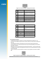
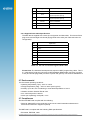
Avnet Embedded.
Support Around The Board™
Avnet Embedded
Specification.
Datasheet
Navman
MDT-860
www.avnet-embedded.eu
MDT-860
Mobile Data Terminal
Data Sheet
Related documents
• MDT-860 Product Brief LA010801
• SDK Reference Manual
• NMEA Reference Manual MN000315
LA010802B © 2008 Navman Wireless OEM Solutions. All rights reserved. Proprietary information and specifications subject to change without notice.
Contents
1.0 Introduction ....................................................................................................... 4
2.0 Technical description ....................................................................................... 4
2.1 Product applications ..................................................................................................... 4
2.2 Physical characteristics ................................................................................................ 4
2.3 Mechanical specification .............................................................................................. 4
2.3.1 Physical dimensions ............................................................................................. 4
2.3.2 Weight .................................................................................................................. 5
2.4 Mounting....................................................................................................................... 5
2.5 Electrical specification.................................................................................................. 6
2.5.1 Graphics LCD display ........................................................................................... 6
2.5.2 Keypad ................................................................................................................. 6
2.5.3 Audio output ......................................................................................................... 6
2.5.4 Main processor .................................................................................................... 6
2.5.5 Non-volatile memory ............................................................................................ 7
2.5.6 Sub processor ...................................................................................................... 7
2.5.7 Power supply ........................................................................................................ 7
2.6 Connectors ................................................................................................................... 7
2.6.1 Serial ports ........................................................................................................... 7
2.6.2 Keyboard interface ............................................................................................... 8
2.6.3 Supplied RJ45 cable specification ....................................................................... 9
2.7 Environmental..............................................................................................................10
2.8 Compliances ...............................................................................................................10
3.0 Electrical requirements .................................................................................. 10
4.0 Software development kit (SDK) ................................................................... 10
4.1 Memory usage .............................................................................................................11
4.2 Compiler, assembler and link editor ............................................................................11
4.3 Make utility ..................................................................................................................11
4.4 Flash download utility - ISP.exe ...................................................................................11
4.5 Library descriptions .....................................................................................................11
4.6 Other tools ...................................................................................................................12
5.0 Product handling............................................................................................. 12
5.1 Packaging and delivery ...............................................................................................12
5.4 Safety ..........................................................................................................................12
5.5 Disposal ......................................................................................................................12
6.0 Ordering information ...................................................................................... 12
7.0 Glossary and acronyms ................................................................................. 13
LA010802B © 2008 Navman Wireless OEM Solutions. All rights reserved. Proprietary information and specifications subject to change without notice.
Figures
Figure 2-1 Physical dimensions .......................................................................................... 4
Figure 2-2 Panavise and standard issue suction mount .................................................... 5
Figure 2-3 Mounting dimensions ........................................................................................ 5
Figure 2-4 Block diagram ................................................................................................... 6
Figure 2-5 Pin-out of RJ45 ................................................................................................ 8
Figure 2-6 Pin-out of RJ12 ................................................................................................. 8
Tables
Table 2-1 Individual part weights ........................................................................................ 5
Table 2-2 Pin-out of left RJ45 socket ................................................................................. 8
Table 2-3 Pin-out of right RJ45 socket ............................................................................... 8
Table 2-4 Pin-out of keyboard RJ12 socket........................................................................ 9
Table 2-5 Pin-out of standard supplied RJ45 cable ........................................................... 9
Table 3-1 Power consumption ...........................................................................................10
Table 6-1 Ordering information..........................................................................................12
LA010802B © 2008 Navman Wireless OEM Solutions. All rights reserved. Proprietary information and specifications subject to change without notice.
1.0 Introduction
The Navman MDT-860 Mobile Data Terminal enables the rapid development of a high quality
customized product for solution providers. The MDT-860 provides a robust field proven, cost
effective hardware platform on which a vast array of products can be built, including: telemetry
devices, modems, RFID readers, barcode scanners, swipe card readers, PLC’s, printers, etc.
All software development is performed in ‘C’, so processor specific knowledge is not required.
The software writer is protected from low-level programming by the comprehensive Application
Programming Interface (API) supplied in the Software Development Kit (SDK).
2.0 Technical description
The MDT-860 has an integrated LCD display, 21 key user keypad, 2x serial connectors and a
PC/2 keyboard interface, all controlled by a high-performance embedded microcontroller.
2.1 Product applications
With the flexibility of the SDK, the MDT-860 has the capability to display text and graphics,
input user keyboard data, and send serial data to a wide variety of custom applications by
interfacing with machinery, cellular modems, remote radios, or any device that can provide serial
connectivity.
The MDT-860 series may also be used in conjunction with the range of Navman cellular and
GPS devices available from Navman Wireless OEM sales. With these devices a cost-effective
tracking and communication system can easily and quickly be built.
2.2 Physical characteristics
The MDT-860 is a complete data message display and text entry terminal enclosed in a
Makroblend UT404 UV-stabilized plastic case, with 25 key conductive carbon non-tactile
elastomer contacts each coated with a pre-labeled matt epoxy finish. The front case is joined to
the backcase using 7 screws. The MDT-860 provides a choice of mounting methods on the rear
of the case.
2.3 Mechanical specification
2.3.1 Physical dimensions
Dimensions in mm
Figure 2-1. Physical dimensions.
LA010802B © 2008 Navman Wireless OEM Solutions. All rights reserved. Proprietary information and specifications subject to change without notice.
2.3.2 Weight
Part Description
Weight (grams)
MDT-860 Terminal
233.0
Bracket (BK000095-G)
55.2
Data Cable (CB000052-G)
108.2
Keyboard Cable (CB000546B-G)
12.25
Table 2-1. Individual part weights.
2.4 Mounting
The MDT-860 features four standard mounting holes fitted with M3 x 6mm brass inserts, and
four small holes in the plastic suitable for attaching the suction cup bracket mount. The standard
unit comes with a suction-cup bracket mount (part number BK000095-G).
There are three options for mounting the MDT-860:
•
•
•
Using the suction mounted, flexible snap-lock bracket provided (standard)
Attached to a standard AMPS plate in-vehicle mount or PanaVise 727-06 bracket.
Panel mounted using the standard 8-hole configuration (see Figure 2-3).
Figure 2-2. PanaVise and standard-issue suction mount.
Figure 2-3. Mounting dimensions.
LA010802B © 2008 Navman Wireless OEM Solutions. All rights reserved. Proprietary information and specifications subject to change without notice.
2.5 Electrical specification
+8 to 30 V supply
RS232
RS232 / RS485
PS/2 Keypad
Power
Supply
LCD
Keypad
Serial I/0
Driver
Keyboard
Sub-processor
Flash ROM
M16
Processor
RAM + Battery
EEPROM
Figure 2-4. Block diagram.
2.5.1 Graphics LCD display
The MDT-860 includes a monochrome graphical LCD display. The graphical display
allows the use of images, variable sized fonts and international fonts. This also allows the
user interface to be laid out in a more professional and user friendly manner.
The display has the following features:
• 320 x 240 pixels
• Four grey scale levels (white, light grey, dark grey, black)
• Wide viewing angle (FSTN LCD)
• Good daylight viewing (transflective LCD)
• Variable level white LED backlighting (PWM controlled)
Because the contrast of an LCD screen is temperature dependant, the MDT-860 also
includes a thermistor temperature sensor. This enables the possibility of automatic
temperature compensation of the LCD contrast value.
2.5.2 Keypad
The MDT-860 has 21 keys and a 4-way cursor key. The keys are a conductive membrane
type. All keys have individual LED backlighting and are de-bounced.
The on/off key is a soft key. The application developer can configure the software to
control the power of any or all of the screen, piezo speaker, backlights, serial ports, and
keyboard sub processor when the on/off key is pressed. This feature allows the MDT860 to always be ready to receive serial data, or wake up periodically as the application
requires.
2.5.3 Audio output
The MDT-860 includes a piezo speaker. The software provides control of the frequency
and volume of the piezo speaker.
2.5.4 Main processor
The embedded processor is a Renesas M16C/62P series 16-bit processor (M30620SPFP)
running at 16MHz. Features include:
• 10KB internal RAM
• multiple serial ports
• multiple timers
LA010802B © 2008 Navman Wireless OEM Solutions. All rights reserved. Proprietary information and specifications subject to change without notice.
2.5.5 Non-volatile memory
The NAVMAN MDT-860 offers:
• Flash memory – 1664KB organized as 2x 832kB pages for program storage.
• RAM - 10KB internal processor RAM, 248KB battery backed RAM organized as 2 x
124KB pages.
• EEPROM - 32KB for data / configuration parameter storage
2.5.6 Sub processor
The MDT-860 contains an additional keyboard sub processor. This is used for the PS/2
keyboard communication. It is an Atmel ATtiny2313 microcontroller and is a low-power
CMOS chip based on the AVR RISC architecture. This typically draws no more than 6mA
at 5V.
The sub processor of the MDT-860 features:
•
•
•
•
2KB of in-system programmable Flash
128B internal SRAM
128B in-system programmable EEPROM
Operates at 8MHz.
2.5.7 Power supply
The MDT-860 series is always powered on whenever the DC supply is connected. The
device can appear to be powered on or off by turning off the LCD, backlight etc in software.
The overall current consumption is dependant on how the application developer programs
the use of the LCD, backlights, RS232 drivers etc.
• Input voltage range +8 to 30V DC
• Reverse polarity protected
The power supply of the MDT-860 has been designed to tolerate typical automotive
transients and has been tested to EN 50082-1. The MDT-860 complies with ISO 7637-1
with the exception of pulse 6. The ISO 7637-1 level used for conformance acceptance is:
• Clause 3.3.1, figure 1 -use 100 for Rs1
• Clause 3.3.2, figure 2 -use 2 for Rs2
2.6 Connectors
There are 3 connectors located on the underside of the MDT-860.
The connectors are:
• Two RJ45 sockets (Female 8P8C)
• One RJ12 socket (Female 6P6C).
2.6.1 Serial ports
The two serial ports are available for connection via the two RJ45 sockets. Both serial
ports feature RTS and CTS handshaking lines. The maximum speed of the serial ports is
115K BPS.
Both connectors include a connection to the single RS485 serial port.
The left hand RJ45 connector contains RS232 serial port 1, and a connection to RS485
serial port 0.
The right hand connector contains RS232 serial port 0, and a connection to RS485 serial
port 0. Serial port 0 is software selectable between RS232 or RS485 and only one is
operational at a time.
The RS485 connection is directly connected internally between both of the RJ45 sockets.
Power may be supplied to either of the RJ45 sockets as these are also directly connected
internally.
LA010802B © 2008 Navman Wireless OEM Solutions. All rights reserved. Proprietary information and specifications subject to change without notice.
Figure 2-5. Pin-out of RJ45 - looking into the socket.
Pin
Signal
Notes
1
Ground
2
+8 to 30V DC
Power supply input (Note: directly
connected to Pin 2 on the right RJ45
socket)
3
HSO1
Handshake output MDT serial port 1
4
TxD1
Data output from MDT serial port 1
5
RxD1
Data input to MDT serial port 1
6
HSI1
Handshake input to MDT serial port 1
7
A
RS485 bus A - serial port 0
8
B
RS485 bus B - serial port 0
Ground
Table 2-2. Pin-out of left RJ45 socket - viewed from front.
Pin
Signal
Notes
1
Ground
2
+8 to 30V DC
Power supply input (Note: directly
connected to Pin 2 on the left RJ45
socket)
3
HSO0
Handshake output MDT serial port 0
4
TxD0
Data output from MDT serial port 0
5
RxD0
Data input to MDT serial port 0
6
HSI0
Handshake input to MDT serial port 0
7
A
RS485 bus A - serial port 0
8
B
RS485 bus B - serial port 0
Ground
Table 2-3. Pin-out of right RJ45 socket - viewed from front.
2.6.2 Keyboard interface
The MDT-860 provides an interface to an external standard PC/AT keyboard. This
connection is provided through the RJ12 connector (left side connector when viewed from
the front).
The keyboard processing is provided by the sub processor (Atmel AVR ATtiny2313
microcontroller), which communicates with the main processor (M16/62P) via an internal
serial data connection.
Keyboards may be connected and disconnected during operation. The sub processor will
re-establish communication with keyboards each time it is reconnected without the need to
reset the MDT-860.
There is a maximum current limitation of 100mA for any keyboard connected to the MDT860.
Figure 2-6. Pin-out of keyboard RJ12 - looking into the socket.
LA010802B © 2008 Navman Wireless OEM Solutions. All rights reserved. Proprietary information and specifications subject to change without notice.
Pin
Signal
Notes
1
AuxOut2
2
Clock
Bi-directional I/O. Keyboard clock.
(keyboard provides pull-up)
3
Data
Bi-directional I/O. Keyboard data.
(keyboard provides pull-up)
4
AuxOut1
5
VCC
6
Ground
DO NOT CONNECT
DO NOT CONNECT
+5 VDC power out: Max 100 mA
Ground
Table 2-4. Pin-out of keyboard RJ12 socket.
2.6.3 Supplied RJ45 Cable Specification
The MDT-860 is supplied with a 2.9m (9.5 foot) power and data cable. This has an RJ45
plug at one end and eight-wire tinned (flying) leads at the other (see Table 2-6 below for
configuration).
Pin
Open lead
1
Orange-white
2
Orange
3
Green-white
4
Blue
5
Blue-white
6
Green
7
Brown-white
8
Brown
Table 2-5. Pin-out of standard supplied RJ45 cable.
Please Note: The Software Development Kit requires a MDT programming cable. This is
a Y cable with a RJ45 plug (connects to MDT-850/860), DB9 female connector (connects
to PC) and tinned flying leads (connects to power and ground). Part number CB000054-G.
2.7 Environmental
Environmental operating conditions:
• operating temperature (Topr): –25ºC to +60ºC
• storage temperature (Tstg): –40ºC to +85ºC (25ºC typical)
• humidity: up to 95% non-condensing or a wet bulb temperature of +35ºC
• vibration: random vibration IEC 68-2-64
• max. vehicle dynamics: 500 m/s
• shock (non-operating): 50 G peak, 11 ms
2.7 Compliances
The Navman MDT-860 complies with the following:
• Directive 2002/95/EC on the restriction of the use of certain hazardous substances in
electrical and electronic equipment (RoHS)
The MDT-860 is compliant with the following EMC specifications:
• EN 55022, EDITION, 1998.
LA010802B © 2008 Navman Wireless OEM Solutions. All rights reserved. Proprietary information and specifications subject to change without notice.
•
•
•
•
47 Code of Federal Regulations Part 15 -Radio Frequency Devices (FCC, part B).
The Motor Vehicle Directive 95/54/EC.
EN 50082-1: 1997.
Complies with E-mark, CE, and C-Tick.
3.0 Electrical requirements
MDT-860 continuous mode power consumption details.
Supply voltage
Backlight ON*
Backlight OFF
Low Power
12.0
118 mA
61 mA
22 mA
13.8
105 mA
54 mA
19 mA
24.0
65 mA
34 mA
13 mA
27.6
58 mA
31 mA
12 mA
All measurements taken without an external keyboard connected.
* Backlight includes LCD screen and all keys.
Table 3-1. Power consumption.
4.0 Software development kit (SDK)
The MDT-860 SDK is designed to speed up application development. The application engineer
can ignore the usual low-level issues that embedded software can present and concentrate on
developing new application software.
The SDK supports two environments:
• the native MDT-860
• an emulation environment using Windows.
The emulator is helpful for development, as debuggers can be used on the PC instead of
requiring costly in-circuit emulation. The Windows emulation environment requires a Windows
C compiler such as Borland C++ builder or Microsoft C++.
Please Note: The Software Development Kit requires a MDT programming cable. This is a Y
cable with a RJ45 plug (connects to MDT-850/860), DB9 female connector (connects to PC) and
tinned flying leads (connects to power and ground). Part number CB000054-G.
4.1 Memory usage
The entire 1664KB (2 x 832KB pages) of Flash memory is available to the application developer,
however some of this space will be used by the SDK libraries which the developer chooses to
link into their software.
Listed below are two examples of the memory usage of a typical application.
Example 1.
SDK supplied Demo application. This is a small application demonstrating most
of the MDT-860 features.
• Application code: 49KB (includes 48.2KB of font data)
• Navman library code: 11.4KB
• C runtime library code: 14.9KB
Total code (Flash) usage: 75.3KB
Total RAM usage: 21.85KB (includes 1.25KB of stack and 18.75KB of LCD
shadow RAM)
Example 2.
A larger application. This example would include multiple display windows, a
communication protocol, storage of messages and many other features.
• Application code 185KB (includes 65.3KB fonts/images)
• Navman library code: 21.4KB
• C runtime library code: 17.5KB
Total code usage: 224KB
Total RAM usage: 117KB)
LA010802B © 2008 Navman Wireless OEM Solutions. All rights reserved. Proprietary information and specifications subject to change without notice.
10
4.2 Compiler, assembler and link editor
The SDK has been designed for the Renesas embedded development tools -the NC30WA ANSI
C compiler. The Renesas NC30WA enables the application developer to write ANSI C language
programs targeted for the Renesas M16C 16-bit core. This also supports in-line assembly,
macros, C library, code optimization and extended functions.
Trial software can be downloaded from the URL: http://www.renesas.com/homepage.jsp
4.3 Make utility
The SDK is supplied with the Gnu Make utility, and example Make scripts for this utility are
included. The scripts compile and link applications, and create binary (BIN) files ready to be
loaded to the MDT.
4.4 Flash download utility - ISP.exe
Navman supplies a Flash download utility (ISP.EXE) which can be used to download the MDT
firmware (.BIN file) to the MDT-860. The Flash download utility is automatically run after a
successful compile and link from the example Make files. This utility runs on Windows 95/98/
2000, NT and XP.
4.5 Library descriptions
The MDT-860 SDK library provides its services arranged by function in several modules. The
following modules are available in the standard SDK.
• Basicio - Basic I/O. This module provides general input and output services such as a fully
controllable piezo speaker, backlight, etc
• Display - LCD display functions. This provides a range of graphics and text functions
for the LCD display. Different fonts can be displayed and a range of graphics routines are
available.
• Timer - Timer functions. A range of timer functions are available. These are based on a
1-millisecond base counter. 15 managed 32-bit timers are provided for application use. A
32-bit roll-over timer and a 1-second 32-bit timer are available. These counters can be used
for developing other timer-based software.
• I2C - EEPROM. Functions are provided to read and write the 32KB (K x 8) EEPROM chip.
• Keypad - Keypad scanning functions. The keypad is serviced by a background interrupt,
which stores keypress information to a key-press queue. Queue management functions are
provided.
• Serial - Serial management functions. The serial ports can be configured in a variety
of ways. The transmit and receive functions are managed in the background. Queue
management functions are provided.
• NMEA - String processing functions. Provides basic functions for NMEA strings, such as
those generated by a GPS receiver
• GPS - String decoding functions. Provides functions to decode the basic GPS strings,
particularly the $GPRMC string.
4.6 Other tools
The SDK is also supplied with some basic tools for converting true type fonts to BDF fonts,
converting BDF fonts to the MDT font format and converting images so they can be displayed on
the MDT LCD display.
For more detailed information refer to the Navman SDK Reference Manual.
5.0 Product handling
5.1 Packaging and delivery
Units are delivered individually bubble wrapped within a carton.
LA010802B © 2008 Navman Wireless OEM Solutions. All rights reserved. Proprietary information and specifications subject to change without notice.
11
The MOQ (Minimum Order Quantity) for shipping is 20 units (1 carton).
5.4 Safety
Improper handling and use of the MDT-860 can cause permanent damage to the device and
may even result in personal injury.
5.5 Disposal
This product should not be treated as household waste. For more detailed information about
recycling of this product, please contact your local waste management authority or the reseller
from whom you purchased the product.
6.0 Ordering information
The MDT-860 and accessories are available using the part numbers shown below:
Part Number
Description
AAA002001-G
MDT-860, OEM unbadged
CB000054-G
MDT-860 Programming Cable (option)
BK000025-G
Panavise mounting bracket (option)
Table 6-1. Ordering information.
For additional MDT parts and accessories please refer to the Navman OEM Price List.
7.0 Glossary and acronyms
API
Application Programming Interface. A set of routines, protocols, and tools
for building software
applications. An API makes it easier to
develop a program by
providing the building blocks.
BDF
Bitmap Distribution
fonts. The content is
be human and computer
CDMA
Code Division Multiple
Access. CDMA refers to the type of
cellular network used
to communicate with the vehicle. It is
a packet transmission
protocol that the cellular modem must
comply with in order for the vehicle to transmit activity data and receive messages.
EEPROM
Electrically Erasable Programmable Read Only Memory. EEPROM is the
memory on a chip that can be stored and erased electronically yet does not lose
data when power is removed. Although it carries the ROM title it can be written
to, slowly. Therefore its only real practical purpose is to store data which will not
change often.
FLASH
Flash Memory. Non-volatile memory (retaining memory when power is off) similar
to an EPROM, but with the ability to be electronically erased and written to. This
enables the flash memory to be easily updated, appended or edited.
FSTN
Film SuperTwisted Nematic. FSTN is a monochrome LCD display technology
characterized by black, high contrast pixels.
GPRS
General Packet Radio Service. GPRS is the packet data protocol on the GSM
Format. A format for storing bitmapped
presented as a text file that is intended to
readable.
LA010802B © 2008 Navman Wireless OEM Solutions. All rights reserved. Proprietary information and specifications subject to change without notice.
12
network. It is used to transmit activity data from the vehicle and to send messages
out to the vehicle.
GPS
Global Positioning System. A space-based radio positioning system that
provides accurate position, velocity and time data.
GSM
Global System for Mobile communication. GSM is a type of cellular
communications network and an alternative to CDMA.
MDT
Mobile Data Terminal. The device fitted onto the dashboard of a vehicle, for twoway messaging between the vehicle and the OnlineAVL application.
NMEA
National Marine Electronics Association. The US standards committee that
defines data message structure, contents and protocols to allow the GPS receiver
to communicate with other pieces of electronic equipment aboard ships.
OEM
Original Equipment Manufacturer. OEMs are manufacturers who resell another
company’s product under their own name and branding.
PWM
Pulse width modulation. Varing a digital pulse high to low time ratio resulting in
the variation of the average value of the waveform.
SDK
Software Development Kit. A programming package that enables a programmer
to develop applications for a specific platform. Typically an SDK includes one or
more API’s, programming tools, and documentation.
SRAM
Static Random Access Memory. SRAM is a type of memory that is faster and
more reliable than the more common DRAM (dynamic RAM). The term static is
derived from the fact that it doesn’t need to be refreshed like dynamic RAM.
Information in this document is provided in connection with Navman Wireless OEM Solutions (“NAVMAN”) products.
These materials are provided by NAVMAN as a service to its customers and may be used for informational purposes
only. NAVMAN assumes no responsibility for errors or omissions in these materials. NAVMAN may make changes
to specifications and product descriptions at any time, without notice. NAVMAN makes no commitment to update the
information and shall have no responsibility whatsoever for conflicts or incompatibilities arising from future changes to its
specifications and product descriptions.
No license, express or implied, by estoppel or otherwise, to any intellectual property rights is granted by this document.
Except as provided in NAVMAN’s Terms and Conditions of Sale for such products, NAVMAN assumes no liability whatsoever.
THESE MATERIALS ARE PROVIDED “AS IS” WITHOUT WARRANTY OF ANY KIND, EITHER EXPRESSED OR IMPLIED, RELATING TO SALE AND/OR USE OF NAVMAN PRODUCTS INCLUDING LIABILITY OR WARRANTIES RELATING TO FITNESS FOR A PARTICULAR PURPOSE, CONSEQUENTIAL OR INCIDENTAL DAMAGES, MERCHANTABILITY, OR INFRINGEMENT OF ANY PATENT, COPYRIGHT OR OTHER INTELLECTUAL PROPERTY RIGHT.
NAVMAN FURTHER DOES NOT WARRANT THE ACCURACY OR COMPLETENESS OF THE INFORMATION, TEXT,
GRAPHICS OR OTHER ITEMS CONTAINED WITHIN THESE MATERIALS. NAVMAN SHALL NOT BE LIABLE FOR
ANY SPECIAL, INDIRECT, INCIDENTAL, OR CONSEQUENTIAL DAMAGES, INCLUDING WITHOUT LIMITATION,
LOST REVENUES OR LOST PROFITS, WHICH MAY RESULT FROM THE USE OF THESE MATERIALS.
NAVMAN products are not intended for use in medical, lifesaving or life sustaining applications. NAVMAN customers using or selling NAVMAN products for use in such applications do so at their own risk and agree to fully indemnify
NAVMAN for any damages resulting from such improper use or sale.
Copyright © 2007, Navman Wirelss OEM Solutions. All Rights Reserved. NAVMAN is a registered trademark of Navman
Wireless OEM Solutions .
LA010802B © 2008 Navman Wireless OEM Solutions. All rights reserved. Proprietary information and specifications subject to change without notice.
13
LA010802B © 2008 Navman Wireless OEM Solutions. All rights reserved. Proprietary information and specifications subject to change without notice.
1
www.avnet-embedded.eu
Avnet Embedded OFFICES.
Denmark
Avnet Embedded
Avnet Nortec A/S
Ellekær 9
2730 Herlev
Phone: +45 3678 6250
Fax: +45 3678 6255
[email protected]
Finland
Avnet Embedded
Avnet Nortec Oy
Tiilenpolttajankuja 3 A B
1720 Vantaa
Phone: +358 207 499260
Fax: +358 942 597446
[email protected]
FrancE
Avnet Embedded
Avnet EMG France SA
Immeuble 154, Parc Chene 2
5, allée du General Benoist
69000 Bron
Phone: +33 4 72 81 02 30
Fax: +33 4 72 81 02 34
[email protected]
Avnet Embedded
Avnet EMG France SA
4, rue de la Couture
Bâtiment Milan, BP 20209
94518 Rungis Cedex
Phone: +33 1 49 78 88 88
Fax: +33 1 49 78 88 89
[email protected]
Avnet Embedded
Avnet EMG France SA
ZA la Hallerais le Semiramis
2, allée du Communel
35770 Vern sur Seiche
Phone: +33 2 99 77 37 02
Fax: +33 2 99 77 33 38
[email protected]
GERMANY (AUSTRIA, CZECH REPUBLIC,
HUNGARY, POLAND, SWITZERLAND)
Avnet Embedded
Avnet EMG GmbH
Gruber Straße 60c
85586 Poing
Phone: +49 8121 775 500
Fax: +49 8121 775 550
[email protected]
UNITED KINGDOM (IRELAND)
Avnet Embedded
Avnet EMG Ltd.
Pilgrims Court, 15/17 West Street
Reigate, Surrey, RH2 9BL
Phone: +44 1737 227800
Fax: +44 1737 243872
[email protected]
Avnet Embedded
Avnet EMG GmbH
Lötscher Weg 66
41334 Nettetal
Phone: +49 8121 775 500
Fax: +49 8121 775 550
[email protected]
ITALY (PORTUGAL, SPAIN)
Avnet Embedded
Avnet EMG Italy SRL
Via Manzoni, 44
20095 Cusano Milanino
Phone: +39 02 66092 1
Fax: +39 02 66092 498
[email protected]
NETHERLANDS (BELGIUM, LUXEMBOURG)
Avnet Embedded
Avnet B.V.
Takkebijsters 2
4802 BL Breda
Phone: +31 76 5722400
Fax: +31 76 5722404
[email protected]
SWEDEN (NORWAY)
Avnet Embedded
Avnet Nortec AB
Esplanaden 3 D
172 67 Sundbyberg
Phone: +46 8 564 725 50
Fax: +46 8 760 01 10
[email protected]
All trademarks and logos are the property of their
respective owners. This document provides a brief
overview only and is not intended to be complete
or binding offer. Product information, including
information related to a product‘s specifications,
uses or conformance with legal or other
requirements, is obtained by Avnet from its suppliers
or other sources deemed reliable and is provided
by Avnet on an „As Is“ basis. Avnet makes no
representation as to the accuracy or completeness
of the product information and Avnet disclaims all
representations, warranties and liabilities under
any theory with respect to the product information,
including any implied warranties of merchantability,
fitness for a particular purpose, title and/or nonrefringement. All product information is subject to
change without notice.
Local Avnet Embedded Businesses:
06/2010