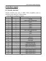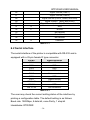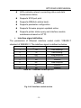
1
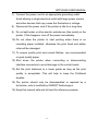
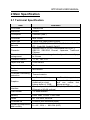
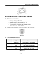
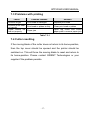
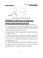
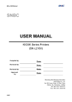
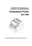
Avnet Embedded.
Support Around The Board™
User manual.
Orient Technologies
BTP-R580
www.avnet-embedded.eu
BTP-R580 USER MANUAL
USER’S MANUAL
Receipt Printer
BTP-R580
Shandong New Beiyang Information Technology Co., Ltd.
ORIENT Technologies bv
BTP-R580 USER MANUAL
Content
Declarations ...................................................................... 1
General Safety Instruction ............................................... 5
1 Introduction.................................................................... 7
1.1 Outline...................................................................................... 7
1.2 Main Features .......................................................................... 7
2 Main Specification ......................................................... 9
2.1 Technical Specification ............................................................ 9
2.2 Cutter Specification................................................................ 10
2.3 Paper Specification ................................................................ 10
2.3.1 Continuous paper ............................................................ 10
2.3.2 Marked paper .................................................................. 12
2.4 Print and cut position ............................................................. 13
2.4.1 Print position ................................................................... 13
2.4.2 Cut position ..................................................................... 14
3 Outline and Parts ......................................................... 15
3.1 Outline and Parts ................................................................... 15
3.2 Error LED and Buzzers.......................................................... 17
4 Installation.................................................................... 19
4.1 Unpacking .............................................................................. 19
4.2 Printer installation .................................................................. 19
4.3 Connecting the Power Adapter.............................................. 20
4.4 Connecting interface cable .................................................... 21
4.5 Connecting the Cash Drawer ................................................ 21
4.6 Paper roll loading ................................................................... 22
-1-
BTP-R580 USER MANUAL
4.6.1 Confirm the paper type ................................................... 22
4.6.2 Load/replace a paper roll ................................................ 22
4.7 Paper near end position adjustment ..................................... 23
4.8 Switching on the printer and printing of self-test ................... 25
4.8.1 Switching on the printer .................................................. 25
4.8.2 Printing a self-test page .................................................. 25
4.9 Setting of printer parameters and configuration .................... 25
5 Printer routine maintenance ....................................... 27
5.1 Cleaning the platen................................................................ 27
5.2 Cleaning the mark sensors .................................................... 27
5.3 Clearing of a paper jam ......................................................... 28
6 Interface signal ............................................................ 29
6.1 Parallel interface .................................................................... 29
6.2 Serial interface ....................................................................... 30
6.3 USB interface......................................................................... 31
6.4 Ethernet interface .................................................................. 31
6.5 WLAN interface...................................................................... 33
6.6 Signal definition of power connector ..................................... 33
6.7 Signal definition of cash drawer interface ............................. 34
7 Troubleshooting .......................................................... 36
7.1 Printer doesn’t work ............................................................... 36
7.2 Alarm LED and buzzer sound................................................ 36
7.3 Problems with printing ........................................................... 37
7.4 Cutter resetting ...................................................................... 37
8. Accessories ................................................................ 38
8.1HERALD – kitchen alarm system ........................................... 38
APPENDIX A: FEED button Configuration ................... 39
-2-
BTP-R580 USER MANUAL
Declarations
Changes without notice
Information in this document is subject to change without notice.
ORIENT Technologies bv (hereinafter referred to as “ORIENT
Technologies”) and SHANDONG NEW BEIYANG INFORMATION
TECHNOLOGY CO., LTD. (hereinafter referred to as “SNBC”)
reserves the right to improve products as new technology,
components, software, and firmware become available. If users
need further data about this product or have any doubt about safety
issues that might arise from using it, please feel free to contact
ORIENT Technologies, SNBC or your local agents.
Copyright
No part of this document may be reproduced or transmitted in any
form or by any means, electronic or mechanical, for any purpose
without the express written permission of ORIENT Technologies or
SNBC.
Copyright © 2007 by SNBC
Printed in China
Version 1.0
-1-
BTP-R580 USER MANUAL
Trademarks
Our registered trademarks are
Warnings and Cautions in this manual
Warning: Items shall be strictly followed to avoid
damages to body and equipment.
Caution:
Items with important information and prompts
for operating the printer.
Certifications
The quality control system of SNBC has been approved of the
following certification.
(DNV)ISO9001:2000
-2-
BTP-R580 USER MANUAL
The environmental control system of SNBC has been approved of
the following certification.
(DNV)ISO14001:2004
BTP-R580 has been approved of the following certification.
WEEE directive 2002/96/EC
ORIENT Technologies bv is complying with all aspects of the
European Union’s WEEE directive 2002/96/EC. All the customers
and end-users can send the products that have reached the end of
their lifes and are to be recycled, to ORIENT Technologies bv.
ORIENT Technologies bv will take care of the recycling of these
products in an environmentally responsible manner in accordance
with WEEE directive.
-3-
BTP-R580 USER MANUAL
Contact us
In CHINA:
Address:
No.169 Huoju Rd, Weihai, Shandong, China. 264209
Hot line:
+86-631-5673777
Fax:
+86-631-5673778
E-mail:
[email protected]
Website:
www.newbeiyang.com (via Contact button)
In EUROPE: ORIENT Technologies bv
Address:
Meerheide 115, 5521 DX Eersel, The Netherlands
Hot line:
+31-497-331080
Fax:
+31-497-386430
Website:
www.orient-technologies.com (via Contact button)
-4-
BTP-R580 USER MANUAL
General Safety Instruction
Before installing and using the printer, please read the following
items carefully:
1. Safety Instructions
Caution: Do not touch the cutter of the printer.
Heating: The print head is at a high temperature during
printing or just after operation. Do not touch it
and its peripherals for reasons of safety.
Warning: The print head is an ESD-sensitive device. To
avoid damage, do not touch either its printing
parts or connecting parts.
2.
. Caution
1) Install the printer on a flat and stable surface.
2) Reserve adequate space around the printer so that convenient
operation and maintenance can be performed.
3) Keep the printer away from water source, direct sunlight, strong
light and heat.
4) Do not use or store the printer in a place exposed to heat or fire,
moisture or other pollution.
5) Do not place the printer in a place exposed to vibration or
impact.
6) No dew condensation is allowed to the printer. In case of such
condensation, do not turn on the power until it has completely
gone away.
-5-
BTP-R580 USER MANUAL
7) Connect the power cord to an appropriate grounding outlet.
Avoid sharing a single electrical outlet with large power motors
and other devices that may cause the fluctuation in voltage.
8) Disconnect the power cord if the printer is idle for a long time.
9) Do not spill water or other electric substances (like metal) on the
printer. If this happens, turn off the power immediately.
10) Do not allow the printer to start printing when there is no
recording paper installed, otherwise the print head and platen
roller will be damaged.
11) To ensure quality print and normal lifetime, use recommended
or good quality paper.
12) Shut down the printer when connecting or disconnecting
interface connectors to avoid damage to the control board.
13) Set the print darkness to a lower grade as long as the print
quality is acceptable. This will help to keep the Printhead
durable.
14) The printer should only be disassembled or repaired by a
technician, who is certified by ORIENT Technologies.
15) Keep this manual safe and at hand for reference purpose.
-6-
BTP-R580 USER MANUAL
1 Introduction
1.1 Outline
The BTP-R580 is a high performance, high speed thermal printer. It
can be widely used for real-time receipt printing applications, such
as for POS systems, restaurant, bars, ATM etc.
The BTP-R580 can be connected to host computers via a parallel
interface, serial interface, USB interface, Ethernet interface or
WLAN interface. The printer can also be connected with
cash-drawers and the Herald kitchen alarm system.
The BTP-R580 offers drivers under
WINDOWS98/NT4.0/2000/XP/VISTA and special utility software to
handle amongst others downloading of logos and fonts.
1.2 Main Features
◇
Full spill proof design (meets IPX1 standard)
◇
Low noise, high printing speed up to 230mm/s
◇
Easy paper loading
◇
Paper front exit and straight paper path for reliable printing
◇
Internal power supply
◇
Easy operation and maintenance
◇
Simple paper jam clearing
◇
Continuous paper or marked paper can be used
◇
Three different paper width
◇
Auto paper cutting
◇
Cash drawer control connector
-7-
BTP-R580 USER MANUAL
◇
Choice from several interfaces (“daughter boards”)
◇
Optional HERALD kitchen alarm system
-8-
BTP-R580 USER MANUAL
2 Main Specification
2.1 Technical Specification
Item
Parameter
Print mode
Thermal line
Resolution
203DPI
Print speed
230mm/s (Max.)
Print width
Max. 80mm
Paper type
Continuous paper/Marked paper
Character
enlargement
Character rotation
UPC-A, UPC-E, EAN-8, EAN-13 , Coda bar, Code39,
ITF , Code128, Code93, Pdf417
Standard ASCII(12×24), compressed ASCII(9×17)
GB2312, GB18030, Korean, Japanese, Traditional
Chinese
All fonts can be enlarged vertically and horizontally up
to 6 times
0°, 90°, 180°, 270°
Paper near end
Photo sensor
Paper end
Photo sensor
Barcode
Character
Printer top cover
position
Printhead overheating
protection
Graphics
Interface
Microswitch
Thermal resistor
Download bitmap
Direct bitmap print
8 figures maximum
download to a total
bitmap buffer of 12KB
Standard parallel, RS232
Ethernet or WLAN optional
Support bitmap mode
and can realize fast
bitmap printing
(25 pins), RS485, USB,
Cash drawer
1-2 cash drawers
Memory
RAM: 2MB, FLASH: 2 MB /4MB
Power
AC 100-220V, 50/60Hz
Printhead life
≥150Km (with reference paper)
Operating temperature
and humidity
5~45℃, 20% ~ 90% RH (40°C)
-9-
BTP-R580 USER MANUAL
Storage temperature
and humidity
Dimension
-40~55℃, 20%~93% (40℃)
147(W)×205(D)×147(H) mm
Table 2.1-1
2.2 Cutter Specification
Item
parameter
Note
Cutter type
Slide cutter
(Guillotine type)
Cutting time
600ms
Cutting interval
2s
Paper type
0.06~0.1mm
Operation voltage
24VDC
Max. static curren
1.2A
2,000,000 cuts
(reference paper
with
thickness of 0.06 mm)
Cutter lifetime
The time that one cut
takes
30 times/min. (Max.)
Thermal paper or paper
with the same thickness
24VDC
Full or partial cuts
Table 2.2-1
Full cut:
Cut off the paper completely;
Partial cut: 2 mm paper left in middle
2.3 Paper Specification
2.3.1 Continuous paper
Paper type:
Continuous thermal paper
Paper supply method:
Paper roll
Paper width:
82.5±0.5mm,80±0.5mm,
57.5±0.5 mm
Paper thickness:
0.06mm-0.1mm
Thermal senstive layer:
Outside
- 10 -
BTP-R580 USER MANUAL
Paper roll specifications
OD(MAX):
ф100 mm
ID(Min):
ф15mm
Recommended reference paper:
Paper type
Manufacturer
TF50KS-E2C
Nippon Paper Industries Co., Ltd
F240AC/F220-VP
Mitsubishi Paper Mill CO., LTD
KF060-FEAH
NEW OJI Paper CO., LTD.
F70NA
FUJI PHOTO FILM CO., LTD
FV230A1,PA220AG,HP220A
Mitsubishi Paper Mill CO., LTD
PD150R,PD160R
OHJI Paper Co.,Ltd.
Table 2.3.1-1 Recommended paper
Caution:
Please use the recommended reference paper type or its
equivalents. Using the lower quality paper types might
affect the print quality and shorten printhead life.
Do not paste the paper to the core.
If the paper is contaminated by a chemical or oil, it may
discolor or lose heat sensitivity at the polluted spot.
Do not rub the paper surface strongly against hard objects,
otherwise it may discolor.
When the temperature goes up to 70 degrees centigrade,
paper will discolor.
Don’t use or store paper under high temperature, high
humidity and strong light conditions.
- 11 -
BTP-R580 USER MANUAL
2.3.2 Marked paper
In marked paper mode, BTP-R580 determines the cut position and
the initial printing position by referencing the position of the black
mark. Black marked paper should meet the following requirement
besides that of standard paper.
L1 Mark length: 3mm≤L1≤10mm.
L2 Mark length: L2≥12mm.
L3 Distance between marks: 20mm≤L3<500mm.
Mark position: Right, middle or left side on paper(80mm
paper only)
Reflectivity: The reflectivity of the black mark must be
less than 15% while the reflectivity of the paper itself
exceeds 85%. There shall be no printed objects like text
and images in the area between the black marks.
Fig.
2.3.2-1: Mark position sketch map
Caution:
The printer will measure the marks during the printing or
feeding process. If the lengths of the mark (L1) is larger than
the default value (default: 13mm), the printer will give a
paper-end alarm.
- 12 -
BTP-R580 USER MANUAL
2.4 Print and cut position
2.4.1 Print position
Fig. 2.4.1-1
L1 Paper holder width: 83.5+0/-0.5mm
L2 Max Print width: 80mm
L3: Distance between left end of printhead and left side of paper
holder(Fixed) 1.8±0.3mm
L4: Distance between right end of printhead and right side of paper
holder(Fixed) 1.8±0.3mm
L5: Left margin (default:7mm)
L6: Print area width. Can set by command (See Programming
manual), default is 64mm.
L7: Right margin (default: 9mm)
- 13 -
BTP-R580 USER MANUAL
2.4.2 Cut position
L1: about: 30mm
L2: about: 11mm
Fig. 2.4.2-1
- 14 -
BTP-R580 USER MANUAL
3 Outline and Parts
3.1 Outline and Parts
1—Paper near end sensor
adjusting lever
2 —Paper holder
3 —Platen roller
4—Middle cover
5—Bottom cover
6 — Power switch
7—Paper guide
8—Top cover
9 — Cover spanner
Fig.3.1-1
10—Printhead
11—Paper roll shaft
12—Printhead support plate
13 —Power connector
14 —Communicate interface
15 —Cash drawer connector
Fig 3.1-2
Functions of parts:
a)
Paper guide
Removing the paper guide or putting it in a different slot will
allow the printer to use different paper widths listed as follows:
82.5±0.5 mm, 80.5±0.5 mm, 57.5±0.5 mm.
- 15 -
BTP-R580 USER MANUAL
b)
Power switch
Switching the power of the printer on or off. “O” power is turned
off. “—” power is turned on.
c)
Feed button (See Fig 3.1-3)
Switching on the printer while pressing the FEED
button will start the printing of the configuration
table。
In normal status:
Continuous paper mode:
The printer will feed one
Fig 3.1-3
line when pressing the FEED button for a short time.
The printer will feed continuously when pressing the
FEED button for a longer time
Marked paper mode:
The printer will feed one line when pressing the FEED
button for a short time.
The printer will locate the marks when pressing the
FEED button for a longer time.
In error status, the printer will have no activity when the
FEED button is pressed.
d)
Power Indicator
Indicating power status (ON/OFF).
e)
Error indicator
Indicating some error status. Under normal conditions, ERROR
LED is always off. Under some error conditions(Cover Open、
Cutter Error、Print head is overheating、Input voltage is
- 16 -
BTP-R580 USER MANUAL
abnormal), ERROR LED will flash.
f)
Paper indicator
Indicating paper status. Under normal conditions, PAPER LED
is always off. When the paper status changes (paper end or
paper near end), PAPER LED will flash.
g)
Paper end sensor
The paper-end sensor is used to detect whether the paper roll
is out of paper.
Notices:
The paper guide is an indispensable part of the printer and
should be kept with the printer.
3.2 Error LED and Buzzers
1) Error LED
Led
Status
Description
Power Indicator(Green)
(POWER)
On
Printer is powered on
Off
Printer is powered off
Off
Printer is in normal status
Flash
Printer is in error status
On
Paper end or near end
Error
Indicator(Red)
(ERROR)
Paper Indicator(Red)
(PAPER)
Flash
Off
Table 3.2-1
- 17 -
Macro definition is running
Printer is in normal status
BTP-R580 USER MANUAL
2) Description of LED and Error Status
Error information
ERROR LED
PAPER LED
Buzzer
Six times
Off
Long-Short-Long
Five times
Off
Short-Short-Long
Cutter Error
Four times
Off
Long-Short-Long
Cover Is Open
Three times
Off
Short-Long-Short
Paper End
Twice
On
Short-Short-Short
Paper near end
Off
On
Finding mark error or
verify failed
Flashing
continuously
Off
Print head is
overheating
Input voltage is
abnormal
Table 3.2-2
Caution:
The temperature of the print-head is detected by means of a
thermistor sensor. If the temperature of the printhead becomes
higher than 650 C, the protection circuit of the printer will force
the printer to stop printing.
- 18 -
BTP-R580 USER MANUAL
4 Installation
4.1 Unpacking
Check whether all items, that are listed on the packing list are
present and in a good condition. If any items are damaged or
missing, please contact your dealer.
4.2 Printer installation
1)
The printer should be installed on a flat and stable horizontal
surface.
2)
The printers should be away from any water source.
3)
Do not place the printer on a surface exposed to vibration or
risk from impact.
4)
Ensure that the printers can be grounded safely.
5)
During operation and maintenance of the printer there should
be sufficient space around the printer in accordance with the
dimensions as shown in fig. 4.2-1.
Fig. 4.2-1 Structure spaces
- 19 -
BTP-R580 USER MANUAL
4.3 Connecting the Power Adapter
1) Ensure the printer power is turned off.
2)
Insert the power cord into the power socket on the backside of the
printer.
3)Fix the power cable cord in the printer with a clip as shown in Fig.
4.3-1.
Fig. 4.3-1
Caution:
When connecting or disconnecting the power cord, always
hold the plug and avoid dragging it by force.
Do not pull on the power cord, otherwise the cord may be
damaged or broken, causing a risk of fire or electric shock.
Do not place the power cord near a heating device, otherwise,
the cover of the cord may melt, causing a risk of fire or electric
shock.
If the printer is not in use for a long period, disconnect the
power cord from the wall outlet for safety.
- 20 -
BTP-R580 USER MANUAL
4.4 Connecting interface cable
1) Ensure the printer power is turned off.
2) Connect the suitable interface cable with the correct connector
to the connector of the interface board of the printer plug screws
(Serial interface) or clip springs (Parallel interface) as shown in
Fig. 4.4-1.
3) Connect the other end of the interface cable to the host.
Fig.4.4-1
4.5 Connecting the Cash Drawer
1)Ensure the printer power is turned off.
2) Insert the cash drawer cable into the cash drawer connector on
the back of the printer.
Fig. 4.5-1
- 21 -
BTP-R580 USER MANUAL
Caution:
Cash drawer interface can be connected only with a cash
drawer device (Do not connect a telephone line and so on).
4.6 Paper roll loading
4.6.1 Confirm the paper type
After connecting of the printer to the mains voltage, with the host
and, if applicable, to the cash drawer, the paper can be loaded and
printed.
4.6.2 Load/replace a paper roll
1) Press the latch of the top cover and open it.
Fig. 4.6.2-1 Opening top cover
2) Place a paper roll in the paper holder as shown the Fig. 4.6.2-2.
Fig. 4.6.2-2 Paper roll load
- 22 -
BTP-R580 USER MANUAL
3) Close the printer top cover.
Caution:
If needed remove the paper guide. Choose the suitable paper
guide position according to the width of the paper roll and
mount the paper guide. When inserting the paper roll pay
attention to the paper path direction (see Fig. 4.6.2-2).
Fig. 4.6.2-3
Note:
Without paper guide:
82.5±0.5mm.
Paper guide in the slot A:
80±0.5mm
Paper guide in the slot B:
57.5±0.5mm
Ensure that the paper is rolled tightly onto the paper roll,
otherwise a paper jam or other fault could happen.
The paper roll should be placed straight in the paper holder and
not slantingly. The paper roll should be able to move freely.
4.7 Paper near end position adjustment
Through adjustment of the latch of the paper near end sensor to a
corresponding
level,
different
- 23 -
paper
roll
cores
can
be
BTP-R580 USER MANUAL
accommodated and also the remaining paper-end length can be
approximated.
Fig 4.7-1
Caution:
The factory setting of the paper near end sensor is level 1.
1) When using different Diameter core shaft, C diameter may be
different with the length of the remaining paper at the same
level.
Fig 4.7-2
- 24 -
BTP-R580 USER MANUAL
4.8 Switching on the printer and printing of self-test
4.8.1 Switching on the printer
1)
Ensure that the printer is connected to the mains voltage and, if
applicable, that the mains voltage is switched on.
2)
Switch on the power of the printer.
4.8.2 Printing a self-test page
1) Confirm that the printer is connected to the mains voltage and
that a paper roll is in the printer.
2) Confirm that the printer is switched off.
3) Press down the FEED button while switching on the printer, the
printer will start printing the configuration sheet. At the end of
the configuration sheet the followings text will appear: “Press
and Release FEED key to print characters” and “Press and Hold
FEED key to config the printer”. The printer is holding and
waiting for the input while the PAPER LED is flashing.
4) If the FEED button is pressed down shortly, the printer will print
a character test page which is part of the self-test.
5) If the FEED button is pressed down for a longer period than the
printer will come in the mode of setting the printer parameters
and configuration by key strokes (See APPENDIX A: FEED
button Configuration).
4.9 Setting of printer parameters and configuration
The parameters of the printer can be set (configuring) in a detailed
way by means of the utility software that is available from the
reseller or from Orient Technologies by special request (website:
- 25 -
BTP-R580 USER MANUAL
www.orient-technologies.com. press button “Contact”). However,
the majority of the parameters can also be set by using the special
key-stroke procedures of the printer. These procedures are simple,
do not involve a laptop but only the FEED button on the key-pad of
the printer. The parameters that can be set by pressing the Feed
button include:
For the serial interface only: setting of baud rate, parity,
data bits, stop bits, handshaking, buffer size and data
receive error.
For all interfaces:
setting of mechanism (mark sensor, cutter, buzzer,
power adapter)
print setting (darkness, paper roll width, left margin,
right margin, CR command, code page)
Paper sensor setting (paper low alarm, paper end
stop)
Set default configuration
To start the key-stroke procedure start the self-test procedure as
described in chapter 4.8 steps 1 through 3. After the printer has
stopped printing the configuration sheet, press and hold the FEED
button until the printer starts printing. The printer will print first the
Main Menu of the key-stroke procedure.
A more detailed overview of all parameters can be found in
Appendix A of this manual.
- 26 -
BTP-R580 USER MANUAL
5 Printer routine maintenance
Caution:
Before starting routine maintenance, ensure that the printer is
switched off.
Do not use solvents like gasoline or acetone.
When cleaning sensors, the printer should not be switched on
until the pure alcohol has totally evaporated.
It is recommended that the maintenance cycle should not be
longer than one month.
5.1 Cleaning the platen
The steps for cleaning the platen are as given below:
1)
Switch off the printer.
2)
Open the top cover of the printer.
3)
When the top cover is opened, wipe off stain such as dust on
the platen by using a soft cotton cloth with neutral cleaning
agent.
4)
Close the top cover after the alcohol has evaporated
completely.
5.2 Cleaning the mark sensors
The black mark sensors need to be cleaned if the printer has trouble
identifying the black marks.
The steps for cleaning sensors are as below:
1)
Switch off the printer.
2)
Open the top cover of the printer.
- 27 -
BTP-R580 USER MANUAL
3)
Wipe off stain or dust from the surface of sensors by using a
soft cotton swipe impregnated with pure alcohol.
4)
Close the top cover of the printer after the alcohol has
evaporated completely.
5.3 Clearing of a paper jam
Remove the paper, if one of the following phenomena occurs:
The printer fails to feed out paper normally.
Paper is feeding with load noise.
The steps for removing paper are as below:
1)
Switch off the printer.
2)
Open the top cover of the printer.
3)
If the paper is jammed in the paper path, remove the wrinkled
or wasted part of the paper roll.
4)
Close the printer top cover.
- 28 -
BTP-R580 USER MANUAL
6 Interface signal
6.1 Parallel interface
Parallel interface can work in IEEE 1284 compatible mode or
half-byte mode, which is a 36 pin socket.
The Interface is defined as below:
Pin#
Signal source
Signal definition
1
H
NStrobe
2
H
Data 0 (Least Significant Bit)
3
H
Data 1
4
H
Data 2
5
H
Data 3
6
H
Data 4
7
H
Data 5
8
H
Data 6
9
H
Data 7 (Most Significant Bit)
10
P
NAck
11
P
Busy
12
P
Perror
13
P
Select
14
H
nAutoFd
15
Not defined
16
Logic Gnd
17
Chassis Gnd
18
P
Peripheral Logic High
19
Signal Ground (nStrobe)
20
Signal Ground (Data 1)
21
Signal Ground (Data 2)
22
Signal Ground (Data 3)
23
Signal Ground (Data 4)
24
Signal Ground (Data 5)
25
Signal Ground (Data 6)
- 29 -
BTP-R580 USER MANUAL
26
Signal Ground (Data 7)
27
Signal Ground (Data 8)
28
Signal Ground (PError, Select, and nAck)
29
Signal Ground
30
(Busy and nFault)
Signal Ground (nAutoFd, nSelctIn, and nInit)
31
H
NInit
32
P
33
NFault
Not defined
34
Not defined
35
Not defined
36
H
nSelectIn
Table 6.1-1
6.2 Serial interface
The serial interface of the printer is compatible with RS-232 and is
equipped with a 25-pin female D type connector.
PIN No.
PIN1
PIN2
Signal definition
Frame Ground
TXD
PIN 3
PIN 4
RXD
DTR
PIN 5
PIN6
Not connected
DSR
PIN 7
PIN 8~19
Signal Ground
Not connected
PIN 20
PIN 21~25
DTR
Not connected
Table 6.2-1
The user may check the current setting status of the interface by
printing a configuration table. The default setting is as follows:
Baud rate: 19200bps, 8 data bit, none Parity, 1 stop bit
Handshake: DTR/DSR
- 30 -
BTP-R580 USER MANUAL
6.3 USB interface
Parameters
Data transmission: Support USB1.1 protocol
Connector (Printer side): USB B type socket. Support and
pass USB HUB
Interface signal definition and functions
Pin No.
Signal
Description
1
VBUS
+5V
2
DATA-
Printer data transmit line minus
3
DATA+
Printer data transmit line plus
4
GND
Ground
Table 6.3-1
Interface connector
Fig. 6.3-2 USB “B” type connector
6.4 Ethernet interface
Feature
Supports 10BASE-T communication
Compatible with Ethernet II standard frame type
- 31 -
BTP-R580 USER MANUAL
LEDs indicate network connecting status and data
transmission status.
Supports 9100 port print
Supports ASB(Auto status back)
Supports parameter configuration
Supports firmware program updated online
Supports printer status query and interface module
maintenance based on HTTP.
Interface signal definition
The parameters of Ethernet interface socket match 10BASE-T
standard of IEEE802.3. The interface signal is defined as below:
Pin
Signal name
Description
1
TX+
Data sending+
2
TX-
Data sending-
3
RX+
Data reception+
4
NC
Reserve
5
NC
Reserve
6
RX-
Data reception-
7
NC
Reserve
NC
Reserve
8
Table 6.4 -1 Interface module pin list
Fig. 6.4-2 Interface module socket
- 32 -
BTP-R580 USER MANUAL
6.5 WLAN interface
Features
Supports 802.11b、802.11g communication
Supports 9100 port print and LPR print
Supports ASB (Auto Status Back)
Supports parameter configuration
Supports firmware program upgraded online
Supports HTTP
Protocols are supported as below
IP
ARP
ICMP
TCP
UDP
DHCP
TFTP
HTTP
WLAN interface uses wireless USB network card of which the main
specification should be requested from the local distributor or
manufacture.
6.6 Signal definition of power connector
Internal signal definition of power
Pin
Signal name
1
E
2
L
3
N
Table 6.6-1
- 33 -
BTP-R580 USER MANUAL
Fig6.6-2 Power socket
6.7 Signal definition of cash drawer interface
1)
Electric characteristics
Driving voltage: DC 24 V
Driving current: Max. current is 1 A
The signal for checking cash drawer status:
“L” = 0~0.5 V “H” = 3.3 V
2)
Cash drawer interface socket uses RJ-11 6P connector.
Fig. 6.7-1
3)
Interface signal definition
No.
Signal
Functions
1
FG
Frame
2
3
DRAWER 1
Driving signal of cash drawer1
DRSW
Check signal for cash drawer status
4
VDR
Cash drawer driving power
5
-
NC
6
GND
Common port with circuit
Table 6.7-2
- 34 -
BTP-R580 USER MANUAL
Caution:
Do not allow disconnection or connection of the interface
cable plug when the printer and the host are switched on.
Avoid the presence of devices like motors with large power as
these may cause voltage fluctuations.
Always use shielded interface cables.
- 35 -
BTP-R580 USER MANUAL
7 Troubleshooting
Refer to this section if the printer has any problems.
If the problem cannot be solved, please consult with ORIENT
Technologies or your supplier..
7.1 Printer doesn’t work
Faults
Possible reasons
Power LED is off and
the printer doesn’t
work
Solution
Printer is off
Connect the printer power
Printer is off
Turn on the printer
Circuit board is damaged
Contact ORIENT or your
supplier
Table 7.1-1
7.2 Alarm LED and buzzer sound
Faults
Paper LED on
and buzzer
sounds
Paper LED on
Alarm LED
flashes and
buzzer sounds
Possible reasons
Paper end
Solution
Replace with new paper roll
Paper near end
Replace with new paper roll
Input voltage is
abnormal
Turn off the printer power and check
The input voltage
Print head is
overheated
Turn off the printer power and wait
for the print head temperature
recovered normally
Cutter Error
Cutter resetting(reference 7.4)
Cover is Open
Close the cover again
Serious fault occurs
Contact with our distributor or
manufacturer
Table 7.2-1
- 36 -
BTP-R580 USER MANUAL
7.3 Problems with printing
Faults
Printout is light
Printout is not clear
or has dirt
Paper cannot be
fed out properly
Possible reasons
Solution
Print head is damaged
Replace print head
Print head or platen is dirty
Clean print head or platen
Paper jam
Open top cover and check
paper path to remove paper jam
Table 7.3-1
7.4 Cutter resetting
If the moving blade of the cutter does not return to its home-position,
then the top cover should be opened and the printer should be
switched on. This will force the moving blade to reset and return to
its home-position. Please contact ORIENT Technologies or your
supplier if the problem persists.
- 37 -
BTP-R580 USER MANUAL
8. Accessories
8.1HERALD – kitchen alarm system
1) Functions
The Herald is connected to the cash drawer connector of the printer.
When the printer sends Cash drawer signal, the Herald will give
sound and light signals.
2) Light and sound signal mode
There are three levels of light signals:
First level:
flash;
Second level: always light;
Third level:
not light.
There are three levels of sound signals:
First level:
sound 1;
Second level: sound 2;
Third level:
sound 3.
3)Supported firmware
The firmware version supporting the Herald should be above
FV1.000. All interfaces support this function.
4)External connection sketch map.
- 38 -
BTP-R580 USER MANUAL
Herald
Fig 8.1-1 External connection sketch map
APPENDIX A: FEED button Configuration
Parameter setting (configuring) by Feed button
1)
Hold the FEED button pressed while switching the printer on.
2)
After the printer has printed the configuration sheet, press and
hold the FEED button to configure the printer. The main menu for
the key-stroke setting procedure is printed.
3)
The procedure consists of several sub-menus and step-by-step
working is needed.
4)
With every choice is a number. This number indicates the
number of times the FEED button has to be shortly pressed. After
this, the choice is validated by an additional, but longer press of
the FEED button (1 sec).
5)
After all settings have been done, they are stored in the printer
by stepping back through the submenus to the main menu by
using the number “1” plus additional press for validation.
- 39 -
BTP-R580 USER MANUAL
Parameter setting by Feed button
Main Menu
Select submenu
Exit
Print Self Test
Configuration
Cutter Test
Sensor Test
>1
>2
>3
>4
>5
Setting configuration of the printer
Configuration
Exit
without
Save
Exit with
Save
Communic
ation
Mech. &
Hardware
Print
Settings
Paper
Sensor
Setting
Set
Default
Config
>1
>2
>3
>4
>5
>6
>7
- 40 -
BTP-R580 USER MANUAL
Configuration of the serial interface
Communication
Back
to last
menu
>1
Baud
Rates
(default:
19200 bps)
>2
Choices:
9600 bps
19200 bps
38400 bps
57600 bps
4800 bps
2400 bps
1200 bps
115200 bps
Parity
(default:
none)
3
Choices
:
None
Odd
Even
Data
Bits
(default:
8 bits)
4
Choices
:
7 Bits
8 Bits
Stop
Bit(s)
(default:
1 Bit)
5
Choices
:
1 Bit
2 Bits
- 41 -
Handshak
ing
(default:
DTR/DSR)
6
Choices:
DTR/DSR
XON/XOFF
Rx Buffer
Size
(default:
4k bytes)
7
Choice:
4k bytes
45 bytes
Data
Receive
Error
(default:
ignored)
8
Choices
:
Ignored
Print “?”
BTP-R580 USER MANUAL
Setting Mechanism and Hardware
Mech. &
Hardware
Back to
last menu
Mark
Sensor
(default:
disabled)
Cutter
(default:
enabled)
Buzzer
(default:
enabled)
Power
Supply
(default:
normal)
>1
>2
>3
>4
>5
Choices:
Enabled
Disabled
Choices:
Enabled
Disabled
Choices:
Enabled
Disabled
Choices:
Normal
Low power
mode
- 42 -
BTP-R580 USER MANUAL
Print Setting
Print Setting
Back to
last
menu
Darknes
s
(default:
normal)
>1
>2
Choices:
Low
Normal
High
Extra
high
Paper
Roll
Width
(default:
80 mm)
>3
Left
Margin
(default:
7 mm)
Right
Margin
(default
: 9 mm)
>4
>5
Choices:
57.5 mm
80.0 mm
82.5 mm
Choices
:
0 mm
1 mm
3 mm
5 mm
7 mm
9 mm
Choice
s:
0 mm
1 mm
3 mm
5 mm
7 mm
9 mm
- 43 -
CR
Comman
d
(default:
disabled)
>6
Choices:
Enabled
Disabled
Code
Page
(default:
PC 437)
>7
Choices:
PC 437
PC 850
PC 852
PC 858
PC 860
PC 863
PC 865
PC 866
PC 1252
Katakana
BTP-R580 USER MANUAL
Paper Near-end Sensor setting
Paper sensor settings
Back to last menu
>1
Paper Low Alarm
(default: enabled)
>2
Choices:
Enabled
Disabled
- 44 -
Stop print when paper low
(default: disabled)
>3
Choices:
Enabled
Disabled
BTP-R580 USER MANUAL
Set Default Configuration
Set default config
Back to last Menu
Set printer to default config
>1
>2
Choices:
Enabled
Disabled
- 45 -
www.avnet-embedded.eu
Avnet Embedded OFFICES.
Denmark
Avnet Embedded
Avnet Nortec A/S
Ellekær 9
2730 Herlev
Phone: +45 3678 6250
Fax: +45 3678 6255
denmark @ avnet-embedded.eu
Finland
Avnet Embedded
Avnet Nortec Oy
Pihatörmä 1 B
02240 Espoo
Phone: +358 20 749 9 260
Fax: +358 20 749 9 280
finland @ avnet-embedded.eu
FrancE
Avnet Embedded
Avnet EMG France SA
Immeuble 154, Parc Chene 2
5, allée du General Benoist
69500 Bron
Phone: +33 4 72 81 02 30
Fax: +33 4 72 81 02 34
bron @ avnet-embedded.eu
GERMANY (AUSTRIA, CZECH REPUBLIC,
HUNGARY, POLAND, SWITZERLAND)
Avnet Embedded
Avnet EMG GmbH
Gruber Straße 60c
85586 Poing
Phone: +49 8121 775 500
Fax: +49 8121 775 550
poing @ avnet-embedded.eu
UNITED KINGDOM (IRELAND)
Avnet Embedded
Avnet EMG Ltd.
Pilgrims Court, 15/17 West Street
Reigate, Surrey, RH2 9BL
Phone: +44 1737 227800
Fax: +44 1737 244698
uk@ avnet-embedded.eu
Avnet Embedded
Avnet EMG GmbH
Lötscher Weg 66
41334 Nettetal
Phone: +49 8121 775 500
Fax: +49 8121 775 550
nettetal@ avnet-embedded.eu
ITALY (PORTUGAL, SPAIN)
Avnet Embedded
Avnet EMG Italy SRL
Via Manzoni, 44
20095 Cusano Milanino
Phone: +39 02 660 92 1
Fax: +39 02 660 92 498
milano @ avnet-embedded.eu
Avnet Embedded
Avnet EMG France SA
14 avenue Carnot
F-91349 MASSY Cedex
Tel: +33 (0)1 64 47 29 29
Fax: +33 (0)1 64 47 99 99
paris @ avnet-embedded.eu
NETHERLANDS (BELGIUM, LUXEMBOURG)
Avnet Embedded
Avnet B.V.
Takkebijsters 2
4817 BL Breda
Phone: +31 76 5722400
Fax: +31 76 5722404
benelux @ avnet-embedded.eu
Avnet Embedded
Avnet EMG France SA
Les Peupliers II
35 avenue des Peupliers
35510 Cesson-Sévigné
Phone: + 33 2 99 77 37 02
Fax: + 33 2 99 77 37 01
rennes @ avnet-embedded.eu
SWEDEN (NORWAY)
Avnet Embedded
Avnet Nortec AB
Esplanaden 3 D
172 67 Sundbyberg
Phone: +46 8 564 725 50
Fax: +46 8 760 01 10
sweden @ avnet-embedded.eu
All trademarks and logos are the property of their
respective owners. This document provides a brief
overview only and is not intended to be complete or
binding offer. Product information, including information
related to a product‘s specifications, uses or conformance
with legal or other requirements, is obtained by Avnet
from its suppliers or other sources deemed reliable and
is provided by Avnet on an „As Is“ basis. Avnet makes
no representation as to the accuracy or completeness
of the product information and Avnet disclaims all
representations, warranties and liabilities under any
theory with respect to the product information, including
any implied warranties of merchantability, fitness for a
particular purpose, title and/or non-refringement. All
product information is subject to change without notice.
03/2012