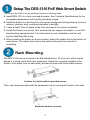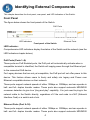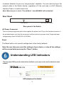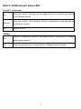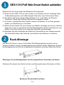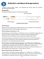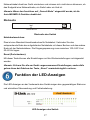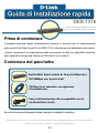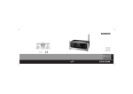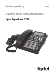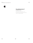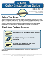
1
DES-1316 Web Smart 16-Port 10/100Mbps Switch with PoE Before Your Begin This Quick Installation Guide gives step-by-step instructions for setting up the D-Link DES-1316 PoE Web-Smart Switch. The model you have purchased may appear slightly different from those shown in the illustrations. For more detailed information about the Switch, its components, making network connections and technical specifications, please refer to the User’s Manual on the master CD included with your switch. Check Your Package Contents Web Smart 16-Port 10/100Mbps Switch with PoE CD-ROM(Containing manual and Utility Installation) AC power cord (Suitable for your area’s electrical power connections) If any item is found missing or damaged, please contact your local reseller for replacement. ©2004 D-Link System, Inc. All rights reserved. Trademarks or registered trademarks are the property of their respective holders. Software and specifications subject to change without notice. 1 Setup The DES-1316 PoE Web Smart Switch The setup of the Switch can be performed using the following steps: A. Install DES-1316 in a fairly cool and dry place. See Technical Specifications for the acceptable temperature and humidity operating ranges. B. Install the Switch in a site free from strong electromagnetic field generators (such as motors), vibration, dust, and direct exposure to sunlight. C. Leave at least 10cm of space at the front and rear of the hub for ventilation. D. Install the Switch on a sturdy, level surface that can support its weight, or in an EIA standard-size equipment rack. For information on rack installation, see the next section titled Rack Mounting. E. When installing the Switch on a level surface, attach the rubber feet to the bottom of each device. The rubber feet cushion the switch and protect the case from scratching. Rack Mounting The DES-1316 can be mounted in an EIA standard-size, 19-inch rack, which can be placed in a wiring closet with other equipment. Attach the mounting brackets at the Switch’s front panel (one on each side), and secure them with the provided screws. Combine the Switch with the provided screws Then, use screws provided with the equipment rack to mount each Switch in the rack. Mount the Switch in the rack 2 Connecting Network Cables The DES-1316 supports 16 10/100M Ethernet ports and Port 1 ~ Port 8 are PoE enabled ports. These PoE ports are automatically activated when a compatible terminal is identified; the Switch will supply power through the Ethernet port to the connected PoE device. For Legacy devices that are not yet compatible, the PoE port will not offer power to this device. This feature allows users to freely and safely mix legacy and Power over Ethernet compatible devices on their network. The Switch supports 10Mbps Ethernet or 100Mbps Fast Ethernet and it runs both in half- and full- duplex mode using two pair of Category 5 cable. These RJ45 ports are Auto-MDI type ports. The Switch can auto transform to MDI-II or MDI-X type, so you can make an easy connection without worrying if you are using a standard or crossover RJ45 cable. AC Power The Switch uses a 100-240V AC, 50-60 Hz power supply. The power switch is located at the rear of the unit adjacent to the AC power connector and the system fan. The Switch’s power supply will adjust to the local power source automatically and may be turned on without having any or all LAN segment cables connected. 3 Identifying External Components This chapter describes the front panel, rear panel, and LED indicators of the Switch. Front Panel The figure below shows the front panels of the Switch. PoE Ports ┌――┐ └――――┘ LED Indicators Front panel of the Switch └―――┘ Ethernet Ports LED Indicator: Comprehensive LED indicators display the status of the Switch and the network (see the LED Indicators chapter below). PoE Ports (Ports 1~8): These ports are PoE Enabled ports, the PoE port will automatically activate when a compatible terminal is identified, the Switch will supply power through the Ethernet port to the connected PoE device. For Legacy devices that are not yet compatible, the PoE port will not offer power to this device. This feature allows users to freely and safely mix legacy and Power over Ethernet compatible devices on their network. These ports support network speeds of either 10Mbps or 100Mbps, and can operate in half- and full- duplex transfer modes. These ports also support automatic MDI/MDIX crossover detection to give true “plug and play” capability. You just need to plug-in the network cable to the Switch directly, regardless of if the end node is a NIC (Network Interface Card) or a switch and a hub. Ethernet Ports (Port 9~16): These ports support network speeds of either 10Mbps or 100Mbps, and can operate in half- and full- duplex transfer modes. These ports also support automatic MDI/MDIX 4 crossover detection to give true “plug and play” capability. You just need to plug-in the network cable to the Switch directly, regardless of if the end node is a NIC (Network Interface Card) or a switch and a hub Note: When the port is set to “Forced Mode”, Auto MDI/MDIX will be disabled. Rear Panel AC Power Connector Reset Button Rear panel of the Switch AC Power Connector: This is a three-pronged connector that supports the power cord. Plug in the female connector of the provided power cord into this connector, and the male into a power outlet. Supported input voltages range from 100-240V AC at 50-60Hz. Reset: The Reset button is to reset all settings back to the factory defaults. Note: Be sure that you record the settings of your device, or else all the settings will be erased when pressing the “Reset” button. Understanding LED Indicators The front panel LEDs provide instant status feedback, and, help monitor and troubleshoot when needed. LED indicators of the Switch 5 Power and CPU LEDs POWER: Power Indicator On When the Power LED lights on, the Switch is receiving power. Off When the Power turns off or the power cord has an improper connection. CPU: Management Indicator Blinking When the CPU is working, the CPU LED is blinking. On/Off The CPU is not working. Ports 1~8 PoE port status LEDs Link/ACT: Link/Activity On Blinking Off When the Link/ACT LED lights on, the respective port is successfully connected to an Ethernet network. When the Link/ACT LED is blinking, the port is transmitting or receiving data on the Ethernet network. There is no link. 100Mbps On Off When the 100Mbps LED lights on, the respective port is connected to a 100Mbps Fast Ethernet network. When the respective port is connected to a 10Mbps Ethernet network. PoE Status Green When the PoE device is connected and the port supplies power successfully. When the following failure occurs on the PoE port: Red Off 9 PoE power short circuit 9 PoE Power over current 9 PoE Power fault No Powered Device is detected. 6 Ports 9~16 Ethernet port status LEDs Link/ACT: Link/Activity On Blinking Off When the Link/ACT LED lights on, the respective port is successfully connected to an Ethernet network. When the Link/ACT LED is blinking, the port is transmitting or receiving data on the Ethernet network. There is no link. 100Mbps On Off When the 100Mbps LED lights on, the respective port is connected to a 100Mbps Fast Ethernet network. When the respective port is connected to a 10Mbps Ethernet network 7 Installing the Web Management Utility The following provides instructions guiding you through the installations of the Web Management utility. 1. Insert the Utility CD in the CD-ROM Drive. 2. From the Start menu on the Windows desktop, choose Run. 3. In the Run dialog box, type D:\Web Management Utility\setup.exe (D:\ depends where your CD-Rom drive is located) and click OK. 4. Follow the on-screen instructions to install the utility. 5. Upon completion, go to Program Files -> web_management_utility and execute the Web Management utility. (Figure 1.) Figure 1. Web Management Utility 8 Configuring the Switch The 8-Port 10/100Mbps Ethernet Web Smart Switch with 8-Port PoE has a Web GUI interface for smart switch configuration. The Switch can be configured through the Web Browser. A network administrator can manage, control, and monitor the Switch from the local LAN. This section indicates how to configure the Switch to enable its smart functions including: Port Settings (Speed/Duplex and Flow Control) VLAN Settings (802.1Q VLAN) Trunking Port Mirroring PoE Settings System Settings Device status and Statistics Login Before you configure this device, note that when the Web Smart Switch is configured through an Ethernet connection, the manager PC must be set on same the IP network. For example, when the default IP address of the Web Smart Switch is 192.168.0.1, then the manager PC should be set at 192.168.0.x (where x is a number between 2 and 254), and the default subnet mask is 255.255.255.0. Open Internet Explorer 5.0 or above Web browser. Enter the IP address http://192.168.0.1 (the factory-default IP address setting) into the address location. (Figure 2.) Figure 2. 9 Through the Web Management Utility, you do not need to remember the IP Address. Select the device shown in the Monitor List of the Web Management Utility to settle the device on the Web Browser. When the following dialog page appears, enter the default password "admin" and press Login to enter the main configuration window. (Figure 3.) Figure 3. After entering the password, the main page appears and the screen will display the device status. (Figure 4.) Figure 4. Device Status 10 Setup Menu When the main page appears, find the Setup menu on the left side of the screen (Figure 5). Click on the setup item that you want to configure. There are 12 options: Port Settings, VLAN Settings, Trunk Settings, Mirror Settings, PoE Settings, Device Status, Statistics, System Settings, Trap Settings, Password Settings, Backup Settings, and Reset Settings as shown in the Main Menu screen. Figure 5. 11 Technical Support You can find software updates and user documentation on the D-Link websites. If you require product support, we encourage you to browse our FAQ section on the Web Site before contacting the Support line. We have many FAQ’s which we hope will provide you a speedy resolution for your problem. For Customers within The United Kingdom & Ireland: D-Link UK & Ireland Technical Support over the Internet: http://www.dlink.co.uk ftp://ftp.dlink.co.uk D-Link UK & Ireland Technical Support over the Telephone: 08456 12 0003 (United Kingdom) +1890 886 899 (Ireland) Lines Open 8.00am-10.00pm Mon-Fri 10.00am-7.00pm Sat & Sun For Customers within Canada: D-Link Canada Technical Support over the Telephone: 1-800-361-5265 (Canada) Mon. to Fri. 7:30AM to 9:00PM EST D-Link Canada Technical Support over the Internet: http://support.dlink.ca email: [email protected] DES-1316 16-Port 10/100 Mbit/s Ethernet Web Smart Switch mit 8 PoE-Anschlüssen Vor dem Start Diese Kurzanleitung hilft Ihnen Schritt für Schritt bei der Installation des DES-1316 PoE Web Smart Switch von D-Link. Das von Ihnen erworbene Modell kann im äußeren Erscheinungsbild leicht von den in den Illustrationen abgebildeten Modellen abweichen. Einzelheiten über das Gerät, seine Komponenten, die Herstellung von Netzwerkverbindungen sowie die technischen Daten können Sie dem Benutzerhandbuch auf der mitgelieferten Master-CD entnehmen. Lieferumfang überprüfen 16-Port 10/100 Mbit/s Ethernet Web Smart Switch mit 8 PoE-Anschlüssen CD-Rom (mit Handbuch und Installationsprogramm) Netzkabel (mit landesspezifischem Stecker) Sollte eines dieser Teile fehlen oder beschädigt sein, wenden Sie sich bitte für Ersatz an Ihren Fachhändler. © 2004 D-Link Systems Inc. Alle Rechte vorbehalten. Marken und eingetragene Marken sind Eigentum ihrer jeweiligen Inhaber. Änderungen vorbehalten. 13 DES-1316 PoE Web Smart Switch aufstellen Beachten Sie bei der Auswahl des Standorts bitte Folgendes: A. Stellen Sie den DES-1316 an einem kühlen und trockenen Ort auf. Zulässige Werte für Betriebstemperatur und Luftfeuchtigkeit finden Sie in den Technischen Daten. B. Der Switch darf keinen starken Magnetfeldern (z. B. in der Nähe von Motoren), Vibrationen, Staub oder direktem Sonnenlicht ausgesetzt werden. C. An Vorder- und Rückwand des Gerätes müssen mindestens 10 cm Platz gelassen werden, um Überhitzung zu vermeiden. D. Stellen Sie den Switch auf einer ebenen und stabilen Unterlage auf, die sein Gewicht tragen kann, oder in einem Rack mit EIA-Standardgröße. Weitere Informationen zum Einbau in ein Rack finden Sie im folgenden Abschnitt „Rackmontage“. E. Befestigen Sie beim Aufstellen des Switch die Gummifüße an der Geräteunterseite. Die Gummifüße federn das Gerät ab und schützen das Gehäuse vor Kratzern. Rack-Montage Der DES-1316 kann in einem 19-Zoll-Rack (EIA-Standardgröße) montiert und mit weiteren Geräten in einem Verkabelungsschrank installiert werden. Befestigen Sie dazu die Montagewinkel mit Hilfe der mitgelieferten Schrauben an beiden Seiten des Switch. Befestigen Sie die Montagewinkel mit den mitgelieferten Schrauben am Switch Montieren Sie danach den Switch mit den zum Rack gehörenden Schrauben im Rack. Montieren Sie den Switch im Rack 14 Netzwerkkabel anschließen Der DES-1316 verfügt über 16 10/100 Mbit/s Ethernet-Anschlüsse. Die PoE-Funktion der Anschlüsse 1–8 wird automatisch aktiviert, wenn eine kompatible Gegenstelle erkannt wird. Die Stromversorgung der angeschlossenen PoE-fähigen Geräte erfolgt dann über den Ethernet-Anschluss des Switch. Die Stromversorgung von Geräten ohne PoE-Funktion über die PoE-Anschlüsse ist nicht möglich. Herkömmliche und PoE-fähige Geräte können jedoch problemlos gemeinsam in einem Netzwerk betrieben werden. Der Switch unterstützt 10 Mbit/s Ethernet bzw. 100 Mbit/s Fast Ethernet und kann mit Hilfe von zwei Kabelpaaren der Kategorie 5 sowohl im Halbduplex- als auch im Vollduplexmodus betrieben werden. Die RJ45-Anschlüsse unterstützen Auto-MDI und werden bei Bedarf automatisch auf MDI-II oder MDI-X umgeschaltet. Es spielt also keine Rolle, ob Sie Standard- oder gekreuztes Kabel zum Anbinden der Endgeräte verwenden. Stromversorgung Der Switch wird mit Wechselstrom im Bereich 100–240 V und 50–60 Hz betrieben. Der Netzschalter befindet sich auf der Rückseite des Gerätes neben dem Netzanschluss und dem Systemlüfter. Die Stromversorgung des Switch passt sich automatisch an die jeweilige Stromquelle an. Der Switch kann eingeschaltet werden, ohne dass bereits LAN-Segmente angeschlossen sind. 15 Äußerlich sichtbare Komponenten In diesem Kapitel werden Vorder- und Rückseite des Switch sowie die einzelnen LED-Anzeigen beschrieben. Vorderseite Die folgende Abbildung zeigt die Vorderseite des Switch. PoE-Anschlüsse ┌――┐ └――――┘ └―――┘ LED-Anzeigen Ethernet-Anschlüsse Vorderseite des Switch LED-Anzeigen: Zahlreiche LED-Anzeigen liefern Statusinformationen zum Switch und zum Netzwerk (siehe Abschnitt über die LED-Anzeigen weiter unten). PoE-Anschlüsse (Anschlüsse 1–8): Diese Anschlüsse sind PoE-fähig, und bei Erkennen einer kompatiblen Gegenstelle wird die PoE-Funktion automatisch aktiviert. Die Stromversorgung angeschlossener PoE-fähiger Geräte erfolgt dann über den Ethernet-Anschluss des Switch. Die Stromversorgung von Geräten ohne PoE-Funktion über die PoE-Anschlüsse ist nicht möglich. Herkömmliche und PoE-fähige Geräte können jedoch problemlos gemeinsam in einem Netzwerk betrieben werden. Die Anschlüsse unterstützen Übertragungsraten von 10 Mbit/s bzw. 100 Mbit/s und können im Halb- und Vollduplexmodus betrieben werden. Die automatische Erkennung von MDI/MDI-X ermöglicht echte Plug & Play-Funktionalität. Sie können das Netzwerkkabel direkt am Gerät einstecken und müssen sich nicht darum kümmern, ob das Endgerät eine Netzwerkkarte, ein Switch oder ein Hub ist. Ethernet-Anschlüsse (Anschlüsse 9–16): Die Anschlüsse unterstützen Übertragungsraten von 10 Mbit/s bzw. 100 Mbit/s und können im Halb- und Vollduplexmodus betrieben werden. Die automatische Erkennung von MDI/MDI-X ermöglicht echte Plug & Play-Funktionalität. Sie können das 16 Netzwerkkabel direkt am Gerät einstecken und müssen sich nicht darum kümmern, ob das Endgerät eine Netzwerkkarte, ein Switch oder ein Hub ist. Hinweis: Wenn der Anschluss auf „Forced Mode“ eingestellt wurde, ist die Auto-MDI/MDI-X-Funktion deaktiviert. Rückseite AC Power Connector Reset Button Rückseite des Switch Netzkabelanschluss: Dies ist eine Standard-Anschlussbuchse für Netzkabel. Verbinden Sie das entsprechende Ende des mitgelieferten Netzkabels mit dieser Buchse und das andere Ende mit der Netzsteckdose. Die Eingangsspannung muss zwischen 100–240 V bei 50–60 Hz liegen. Reset (Zurücksetzen): Mit dieser Taste können alle Einstellungen auf die Werkseinstellungen zurückgesetzt werden. Hinweis: Sichern Sie alle am Gerät vorgenommenen Einstellungen, andernfalls gehen diese bei Drücken der Taste „Reset“ unwiederbringlich verloren. Funktion der LED-Anzeigen Die LED-Anzeigen an der Vorderseite des Geräts zeigen den gegenwärtigen Status an und erleichtern Überwachung und Fehlerbehebung. LED-Anzeigen des Switch 17 LED-Anzeigen „Power“ (Stromversorgung) und „CPU“ (Prozessor) POWER: Betriebsanzeige An Bei leuchtender Betriebsanzeige wird der Switch korrekt mit Strom versorgt. Aus Bei fehlender Stromversorgung oder losem Netzkabel. CPU: Prozessor-Betriebsanzeige Blinkend Bei Prozessoraktivität blinkt die LED. An/Aus Der Prozessor ist inaktiv. Statusanzeigen der PoE-Anschlüsse 1–8 Link/ACT: Verbindung/Aktivität An Blinkend Aus Bei leuchtender Link/ACT-LED ist der entsprechende Anschluss korrekt mit einem Ethernet-Netzwerk verbunden. Bei blinkender Link/ACT-LED werden am entsprechenden Anschluss Daten versendet oder empfangen. Keine Verbindung. 100 Mbit/s An Aus Bei leuchtender 100 Mbit/s-LED ist der entsprechende Anschluss mit einem 100 Mbit/s Fast Ethernet-Netzwerk verbunden. Der entsprechende Anschluss ist mit einem 10 Mbit/s Ethernet-Netzwerk verbunden. PoE-Status Grün Das angeschlossene PoE-fähige Gerät wird korrekt mit Strom versorgt. Bei Auftreten folgender Fehler am PoE-Anschluss: Rot Kurzschluss der PoE-Stromversorgung Überstrom in der PoE-Stromversorgung Ausfall der PoE-Stromversorgung Aus Kein PoE-fähiges Gerät erkannt. 18 Statusanzeigen der Ethernet-Anschlüsse 9–16 Link/ACT: Verbindung/Aktivität An Blinkend Aus Bei leuchtender Link/ACT-LED ist der entsprechende Anschluss korrekt mit einem Ethernet-Netzwerk verbunden. Bei blinkender Link/ACT-LED werden am entsprechenden Anschluss Daten versendet oder empfangen. Keine Verbindung. 100 Mbit/s An Aus Bei leuchtender 100 Mbit/s-LED ist der entsprechende Anschluss mit einem 100 Mbit/s Fast Ethernet-Netzwerk verbunden. Der entsprechende Anschluss ist mit einem 10 Mbit/s Ethernet-Netzwerk verbunden. 19 Webgestütztes Verwaltungs-Dienstprogramm installieren Das Verwaltungs-Dienstprogramm wird wie folgt installiert: 1. Legen Sie die CD-ROM mit dem Dienstprogramm in Ihr CD-ROM-Laufwerk ein. 2. Klicken Sie auf dem Desktop im Menü Start auf Ausführen. 3. Geben Sie im Dialogfeld Ausführen folgende Befehlszeile ein: D:\Web Management Utility\setup.exe (hierbei steht „D:“ für den Laufwerksbuchstaben Ihres CD-ROM-Laufwerks). Klicken Sie anschließend auf OK. 4. Befolgen Sie die Installationsanweisungen auf dem Bildschirm. 5. Klicken Sie nach Abschluss der Installation zum Starten des Verwaltungs-Dienstprogramms auf Start -> Programme -> web_management_utility. (Abbildung 1) Abbildung 1. Webgestütztes Verwaltungs-Dienstprogramm 20 Switch konfigurieren Der 16-Port 10/100 Mbit/s Ethernet Web Smart Switch mit 8 PoE-Anschlüssen verfügt über eine Schnittstelle zur webbasierten Konfiguration und kann über einen Webbrowser konfiguriert werden. Netzwerkadministratoren können den Switch über das lokale Netzwerk (LAN) verwalten, steuern und überwachen. In diesem Abschnitt wird beschrieben, wie Sie unter anderem folgende Smart Switch-Funktionen konfigurieren können. Anschlusseinstellungen (Geschwindigkeit/Deaktivieren und Flusskontrolle) VLAN-Einstellungen (802.1Q VLAN) Trunking (Parallelschaltung mehrerer Anschlüsse) Port-Spiegelung PoE-Einstellungen Systemeinstellungen Gerätestatus und Statistik Anmeldung Damit der Switch über eine Netzwerkverbindung konfiguriert werden kann, muss sich der PC, von dem aus die Konfiguration erfolgen soll, im gleichen Adressbereich des IP-Netzwerks befinden. Wenn beispielsweise die Standard-IP-Adresse des Web Smart Switch 192.168.0.1 ist, muss die IP-Adresse des Verwaltungs-PCs 192.168.0.x lauten (wobei x für eine Zahl zwischen 2 und 254 steht). Die Standard-Subnetzmaske lautet 255.255.255.0. Verwenden Sie dazu Internet Explorer 5.0 oder eine aktuellere Browser-Version. Geben Sie in der Adresszeile des Webbrowsers die werkseitige Standard-IP-Adresse http://192.168.0.1 ein. (Siehe Abbildung 2) Abbildung 2 21 Wenn Sie für die Eingabe das webgestützte Verwaltungs-Dienstprogramm verwenden, müssen Sie sich die IP-Adresse nicht merken. Wählen Sie das in der Überwachungsliste des Dienstprogramms angezeigte Gerät aus, um es in den Webbrowser einzufügen. Geben Sie in das unten abgebildete Dialogfeld das Standard-Kennwort „admin“ ein, und klicken Sie auf „Login“ (anmelden). (Siehe Abbildung 3) Abbildung 3 Nach Eingabe des Kennworts wird die Hauptseite eingeblendet, und der Gerätestatus wird angezeigt. (Abbildung 4) Abbildung 4 – Gerätestatus 22 Setup-Menü Auf der Hauptseite befindet sich links das Setup-Menü (Abbildung 5). Klicken Sie auf den Menüpunkt, der konfiguriert werden soll. Es stehen elf Menüpunkte zur Auswahl: Port-Einstellungen, VLAN-Einstellungen, Trunk-Einstellungen (Anschlüsse parallel schalten), Mirror-Einstellungen (Port-Spiegelung), PoE-Einstellungen, Gerätestatus, Statistik, Systemeinstellungen, Trap-Einstellungen, Kennworteinstellungen, Backup-Einstellungen (Sicherung) und Reset-Einstellungen (Zurücksetzen), wie im Bildschirm des Hauptmenüs dargestellt. Abbildung 5 23 Technische Unterstützung Aktualisierte Versionen von Software und Benutzerhandbuch finden Sie auf der Website von D-Link. D-Link bietet kostenfreie technische Unterstützung für Kunden innerhalb Deutschlands, Österreichs, der Schweiz und Osteuropas. Unsere Kunden können technische Unterstützung über unsere Website, per E-Mail oder telefonisch anfordern. Web: http://www.dlink.de E-Mail: [email protected] Telefon: +49 (1805)2787 0,12€/Min aus dem Festnetz der Deutschen Telekom. Telefonische technische Unterstützung erhalten Sie Montags bis Freitags von 09.00 bis 17.30 Uhr. Unterstützung erhalten Sie auch bei der Premiumhotline für D-Link Produkte unter der Rufnummer 09001-475767 Montag bis Freitag von 6-22 Uhr und am Wochenende von 11-18 Uhr. 1,75€/Min aus dem Festnetz der Deutschen Telekom. Wenn Sie Kunde von D-Link außerhalb Deutschlands, Österreichs, der Schweiz und Osteuropas sind, wenden Sie sich bitte an die zuständige Niederlassung aus der Liste im Benutzerhandbuch. . DES-1316 Web Smart 16-Port 10/100Mbps Switch with PoE Avant de commencer Le présent guide d’installation rapide se propose de vous guider pas à pas dans le paramétrage du switch Web-Smart PoE DES-1316 D-Link. Le modèle que vous avez acheté peut présenter de légères différences par rapport aux illustrations du présent manuel. Pour obtenir davantage d’informations à propos du switch, de ses éléments, de la façon d’effectuer les connexions réseau ou des spécifications techniques de l’appareil, veuillez vous reporter au manuel utilisateur contenu dans le CD fourni avec le switch. Vérifiez le contenu de votre coffret Web Smart 16-Port 10/100Mbps Switch with PoE CD-Rom (contenant le manuel et le programme d’installation de l’utilitaire) Cordon d’alimentation secteur avec les prises de votre pays) (compatible Si l’un de ces éléments manque ou est endommagé, veuillez prendre contact avec votre revendeur en vue d’un remplacement. ©2004 D-Link Systems, Inc. Tous droits réservés. Les marques sont la propriété de leurs propriétaires respectifs. Le logiciel et les spécifications sont susceptibles d’être modifiés sans préavis. 25 Paramétrage du switch Web Smart PoE DES-1316 Le paramétrage du switch se compose des étapes suivantes : A. Placez le DES-1316 dans un endroit relativement frais et sec. Reportez-vous aux spécifications techniques pour connaître les plages de température et d’humidité acceptables en fonctionnement. B. Placez le switch à l’abri des sources de champs électromagnétiques intenses (moteurs par exemple), des vibrations, de la poussière et de l’exposition directe à la lumière solaire. C. Préservez pour la ventilation un espace d’au moins 10cm devant et derrière le hub. D. Placez le switch sur un plan horizontal à même de supporter le poids de l’appareil ou dans une baie EIA destinée aux équipements de dimensions standard. Pour des détails concernant la fixation dans la baie, veuillez vous reporter à la section suivante, Fixation dans la baie. E. En cas d’installation du switch sur un plan horizontal, montez sous chaque appareil les pieds en caoutchouc. Ils amortissent les chocs auquel est exposé le hub et évitent les rayures au boîtier. Fixation dans une baie Il est possible de fixer le DES dans une baie de 19 pouces aux dimensions standard EIA, qui peut être placée dans un local de câblage avec d’autres équipements. Placez les deux équerres de fixation de part et d’autre de la face avant du switch (une sur chaque flanc), et fixez-les à l’aide des vis fournies. Assemblage du switch à l’aide des vis fournies 26 Servez-vous ensuite des vis qui accompagnent la baie pour fixer chacun des switches dans la baie. Fixation du switch dans la baie Raccordement du câble réseau Le DES-1316 comporte 16 ports Ethernet 10/100M ; les ports 1 à 8 sont des ports PoE automatiquement activés en présence d’un terminal compatible ; le switch fournit alors l’alimentation de l’équipement PoE connecté à travers le port Ethernet. En cas de branchement d’équipements plus anciens qui ne sont pas encore compatibles, le port PoE ne les alimentera pas. Ceci permet aux utilisateurs de combiner sans risque, au sein d’un même réseau, les équipements compatibles avec l’alimentation par câble Ethernet avec les autres. Le switch prend en charge aussi bien l’Ethernet à 10Mbits/s que l’Ethernet rapide à 100Mbits/s. Il fonctionne à la fois à l’alternat et en duplex au moyen de deux paires de câbles de catégorie 5. Ces ports RJ45 sont de type Auto-MDI. Le switch peut automatiquement les configurer en type MDI-II ou MDI-X ; vous devez juste effectuer le branchement sans vous soucier de savoir si vous utilisez un câble RJ45 droit ou croisé. Alimentation secteur Le switch accepte une alimentation secteur alternative 100-240V, 50-60 Hz. L’interrupteur de mise sous tension se trouve à l’arrière de l’appareil à côté du connecteur d’alimentation secteur et du ventilateur. L’alimentation du switch s’adapte automatiquement aux caractéristiques de votre réseau électrique ; le switch peut être allumé indépendamment de l’état de raccordement des câbles du réseau local. 27 Description des éléments externes Le présent chapitre décrit la face avant, la face arrière ainsi que les voyants lumineux du switch. Face avant La figure ci-dessous représente la face avant du switch. Ports PoE ┌――┐ └――――┘ Voyants lumineux Face avant du switch └―――┘ Ports Ethernet Voyants lumineux: Les voyants lumineux fournissent une représentation détaillée de l’état du switch et du réseau (voir ci-dessous le chapitre consacré aux voyants lumineux). Ports PoE (Port 1~8): Il s’agit de ports PoE activables ; le port PoE est automatiquement mis en service en présence d’un terminal compatible, fournissant ainsi à l’équipement PoE connecté son alimentation à travers Ethernet. En présence d’équipements plus anciens qui ne sont pas encore compatibles, le port PoE ne les alimentera pas. Ceci permet aux utilisateurs de mélanger sans risque, au sein d’un même réseau les équipements supportant l’alimentation par câble Ethernet avec les autres. Ces ports supportent aussi bien des vitesses réseau de 10Mbits/s que 100Mbits/s ; ils peuvent fonctionner à l’alternat et en duplex. Ces ports sont également dotés de la détection automatique MDI/MDX qui permet de disposer d’une véritable fonctionnalité « plug-and-play » : il suffit de brancher directement le câble réseau dans le hub sans se soucier de savoir si le nœud en face est une carte d’interface réseau ou un switch/hub. Ports Ethernet (Port 9~16): Ces ports supportent aussi bien des vitesses réseau de 10Mbits/s que 100Mbits/s ; ils peuvent fonctionner à l’alternat et en duplex. Ces ports sont également dotés de la détection automatique MDI/MDX qui permet de disposer d’une véritable fonctionnalité « plug-and-play » : il suffit de brancher directement le câble réseau dans le hub sans se soucier de savoir si le nœud en face est une carte d’interface réseau ou un switch/hub. 28 Remarque : Si le port est paramétré en « mode imposé », la détection automatique MDI/MDIX est désactivée. Face arrière AC Power Connector Reset Button Face arrière du switch Connecteur d’alimentation secteur : C’est dans ce connecteur à trois broches que vient s’enficher le cordon d’alimentation secteur. Branchez la partie femelle du cordon secteur fourni dans le connecteur et la partie mâle dans une prise murale. Les tensions acceptées doivent être comprises entre 100 et 240 V alternatif pour une fréquence située entre 50 et 60Hz. Remise à zéro : Le bouton de remise à zéro sert à réinitialiser tous les réglages à la valeur par défaut qui leur a été attribuée en usine. Remarque : Assurez-vous d’avoir enregistré les réglages de votre appareil faute de quoi ils seraient tous perdus en cas d’appui sur le bouton de « remise à zéro ». Signification des voyants lumineux Les voyants lumineux situés en face avant fournissent une image toujours fidèle de l’état du système. Il permettent de surveiller le fonctionnement de l’appareil et d’investiguer d’éventuels problèmes. Les voyants lumineux du switch 29 Les voyants d’alimentation et d’unité centrale Power : Témoins d’alimentation Allumé Le switch est alimenté. Eteint Le switch n’est plus alimenté ou le cordon secteur est mal branché. CPU : Témoins de bon fonctionnement Clignotant Lorsque l’unité centrale fonctionne, le voyant CPU clignote. Allumé/Eteint L’unité centrale ne fonctionne pas. Voyants d’état des ports PoE (ports 1~8) Link/ACT : Connexion/Activité Allumé Clignotant Eteint Quand le voyant Link/ACT (Connexion/Activité) est allumé, le port correspondant est correctement connecté à un réseau Ethernet. Quand le voyant Link/ACT (Connexion/Activité) clignote, le port transmet ou reçoit des données sur le réseau Ethernet. Pas de connexion. 100Mbps Allumé Eteint Quand le voyant 100Mbps est allumé, le port correspondant est connecté à un réseau Ethernet rapide à 100Mbits/s. Le port correspondant est connecté à un réseau Ethernet à 10Mbits/s. Etat PoE Vert Un équipement PoE est connecté et le port l’alimente sans problème.. Le port PoE est confronté à l’un des problèmes suivants : Rouge Alimentation PoE en court-circuit Trop de courant demandé à l’alimentation PoE Défaut de l’alimentation PoE Eteint Pas d’équipement à alimenter détecté 30 Voyants d’état des ports Ethernet (ports 9~16) Link/ACT : Connexion/Activité Allumé Clignotant Eteint Quand le voyant Link/ACT (Connexion/Activité) est allumé, le port correspondant est correctement connecté à un réseau Ethernet. Quand le voyant Link/ACT (Connexion/Activité) clignote, le port transmet ou reçoit des données sur le réseau Ethernet. Pas de connexion. 100Mbps Allumé Eteint Quand le voyant 100Mbps est allumé, le port correspondant est connecté à un réseau Ethernet rapide à 100Mbits/s. Le port correspondant est connecté à un réseau Ethernet à 10Mbits/s. 31 Installation de l’utilitaire de gestion web Vous trouverez ci-après les instructions pour vous guider dans l’installation de l’utilitaire de gestion web. 1. Introduisez dans le lecteur le CD contenant l’utilitaire. 2. A partir du menu démarrer du bureau Windows, choisissez Exécuter. 3. Dans la boîte de dialogue Exécuter, saisissez D:\Web Management Utility\setup.exe (D:\ représente la lettre affectée à votre lecteur de CD-ROM) puis cliquez sur OK. 4. Pour installer l’utilitaire, suivez ensuite les instructions s’affichant à l’écran. 5. A la fin, allez à Tous les programmes -> web_management_utility et exécutez l’utilitaire de gestion web. (Figure 1.) Figure 1. Utilitaire de gestion web 32 Configuration du switch Le switch Web Smart Ethernet 10/100Mbps 16-Port doté de 8 ports PoE dispose d’une interface utilisateur web permettant une configuration aisée du switch. Il peut être configuré à l’aide d’un navigateur web. Un administrateur réseau est en mesure de gérer, contrôler et surveiller le switch depuis le réseau local. La présente section montre comment configurer le switch pour en activer les fonctionnalités avancées parmi lesquelles : Paramétrage des ports (vitesse/désactivation et contrôle de flux) Paramétrage du réseau local virtuel (802.1Q VLAN) Agrégation de liens Duplication de port Paramétrage PoE Paramétrage système Etat et statistiques de l’équipement Début de session Si souhaitez configurer cet équipement au travers d’une connexion Ethernet, il vous faut veiller à ce que l’ordinateur de configuration dispose d’une adresse IP sur le même réseau. Par exemple, en supposant que l’adresse IP du switch Web Smart soit 192.168.0.1, l’adresse de l’ordinateur de configuration doit être de la forme 192.168.0.x (où x est un entier compris entre 2 et 254), et l’adresse de sous-réseau par défaut est 255.255.255.0. Ouvrez le navigateur web Internet Explorer 5.0 (ou une version supérieure). Saisissez l’adresse IP http://192.168.0.1 (l’adresse IP par défaut affectée en usine) dans l’emplacement de saisie d’adresse. (Figure 2.) Figure 2. 33 Avec l’utilitaire de gestion web, il est inutile de se souvenir de l’adresse IP ; il suffit de sélectionner l’équipement souhaité dans la liste des équipements présents dans l’utilitaire de gestion web pour le désigner au navigateur web. Quand la boîte de dialogue suivante apparaît, saisissez le mot de passe par défaut « admin » puis cliquez sur « Login »(Ouverture de session) pour accéder à la fenêtre principale de configuration. (Figure 3.) Figure 3. Après la saisie du mot de passe, la page principale apparaît ; l’état de l’appareil est affiché à l’écran. (Figure 4.) Figure 4. Etat de l’appareil 34 Menu de configuration Sur la page principale, le menu de configuration se trouve à gauche de l’écran (Figure 5). Cliquez sur l’élément que vous souhaitez paramétrer. Onze possibilités sont offertes : Port Settings (Paramétrage des ports), VLAN Settings (Paramétrage du réseau local virtuel), Trunk Settings (Paramétrage de l’ agrégation de liens), Mirror Settings (Paramétrage de la duplication de port), PoE Settings (Paramétrage PoE), Device Status (Etat de l’équipement), Statistic (Statistiques), System Settings (Paramétrage système), Trap Setting (Paramétrage des pièges), Password Settings (Paramétrage des mots de passe), Backup Settings (Paramétrage des sauvegardes) et Reset Settings (Paramétrage de la remise à zéro) ; ces choix se retrouvent sur l’écran contenant le menu principal. Figure 5. 35 Assistance technique Vous trouverez la documentation et les logiciels les plus récents sur le site web D-Link. Vous pouvez contacter le service technique de D-Link par notre site internet ou par téléphone. Support technique destiné aux clients établis en France: Assistance technique D-Link par téléphone : 0820 0803 03 N° INDIGO - 0,12€ TTC/min* *Prix en France Métropolitaine au 3 mars 2005 Du lundi au samedi – de 9h00 à 19h00 Assistance technique D-Link sur internet : http://www.dlink.fr e-mail : [email protected] Support technique destiné aux clients établis au Canada : Assistance technique D-Link par téléphone : (800) 361-5265 Lun.-Ven. 7h30 à 21h00 HNE. Assistance technique D-Link sur internet : http ://support.dlink.ca e-mail : [email protected] DES-1316 Conmutador inteligente web Ethernet 10/100 Mbps de 16 puertos DES-1316, con 8 puertos PoE. Antes de empezar Esta Guía de instalación recoge las instrucciones detalladas para configurar el conmutador inteligente web PoE D-Link DES-1316. El modelo adquirido puede ser ligeramente distinto del de las ilustraciones. Si desea información más detallada sobre el conmutador, sus componentes, el modo de establecer las conexiones de red y las especificaciones técnicas, consulte el Manual del usuario que se encuentra en el CD-ROM, incluido con el conmutador. Comprobación del contenido del paquete Conmutador inteligente web Ethernet 10/100 Mbps de 16 puertos DES-1316, con 8 puertos PoE. CD-ROM (contiene Manual y utilidad de instalación) Cable de alimentación AC (adecuado para el tipo de conexiones propias de su país) Si falta alguno de los componentes o está en mal estado, por favor, contacte con su proveedor para que se lo proporcione de nuevo. ©2004 D-Link Systems, Inc. Reservados todos los derechos. Las marcas o marcas registradas son propiedad de los respectivos titulares. El software y las especificaciones pueden ser modificados sin previo aviso. 37 Configuración del conmutador inteligente web PoE DES-1316 Para configurar el conmutador, realice los pasos siguientes: A. Instale el DES-1316 en un lugar fresco y seco. En las “Especificaciones técnicas” se indica el rango aceptable de temperatura y humedad de funcionamiento. B. Instale el conmutador en un lugar en el que no haya generadores de campos electromagnéticos (como motores), vibraciones ni polvo, y que no esté expuesto a la luz directa del sol. C. Deje, como mínimo, un espacio de 10 cm por delante y por detrás del hub para la ventilación. D. Instale el conmutador en una superficie plana y resistente, que soporte el peso del dispositivo, o en un rack de tamaño estándar EIA. En la siguiente sección, “Montaje del rack”, figura información sobre la instalación del rack. E. Al instalar el conmutador en una superficie plana, fije los pies de goma en la parte inferior del dispositivo. Los pies de goma protegen el hub de posibles arañazos. Montaje del rack El DES-1316 puede montarse en un rack de 19 pulgadas, tamaño estándar EIA, que puede colocarse en un armario de cableado junto con otros equipos. Fije los ángulos de montaje a cada lado del panel frontal del conmutador con los tornillos suministrados. Fijación del conmutador con los tornillos suministrados Con los tornillos suministrados monte el conmutador en el rack. Montaje del conmutador en el rack 38 Conexión del cable de red El DES-1316 soporta 16 puertos Ethernet a 10/100 Mbps, de los que los 8 primeros puertos son PoE. Estos puertos PoE se activan automáticamente cuando se identifica un terminal compatible; por medio del puerto Ethernet, el conmutador proporcionará alimentación al dispositivo PoE conectado. Para los dispositivos existentes que no son compatibles, el puerto PoE no proporcionará alimentación a este dispositivo. Esto permite al usuario poder mezclar sin ningún problema dispositivos existentes con dispositivos compatibles con Power over LAN en la red. El conmutador soporta Ethernet a 10 Mbps o Fast Ethernet a 100 Mbps y funciona tanto en modo half duplex como full duplex por medio de dos pares de cables de categoría 5. Los puertos RJ45 son puertos Auto-MDI. El conmutador se puede transformar en tipo MDI-II o en tipo MDI-X; por ello, usted puede realizar la conexión con toda facilidad, sin preocuparse por si el cable que utiliza es RJ45 crossover o estándar. Alimentación AC El conmutador utiliza la toma de alimentación AC 100-240 V AC, 50-60 Hz. El interruptor de alimentación se encuentra en la parte posterior del dispositivo, junto al conector de alimentación AC y al sistema de ventilación. La toma de alimentación del conmutador se ajusta automáticamente a la fuente de alimentación local y puede encenderse sin que haya ningún cable de segmento LAN conectado. 39 Identificación de los componentes externos En este capítulo se describe el panel frontal, el panel trasero y los indicadores LED del conmutador. Panel frontal En la imagen siguiente se muestra el panel frontal del conmutador. Puertos PoE ┌――┐ └――――┘ Indicadores LED └―――┘ Puertos Ethernet Panel frontal del conmutador Indicadores LED: Los indicadores LED informan del estado del conmutador y de la red (vea el capítulo siguiente). Puertos PoE (Puertos 1~8): Estos puertos son puertos PoE. El puerto PoE se activa automáticamente cuando se identifica un terminal compatible; por medio del puerto Ethernet, el conmutador proporcionará alimentación al dispositivo PoE conectado. Para los dispositivos existentes que no son compatibles, el puerto PoE no proporcionará alimentación a este dispositivo. Esto permite al usuario poder mezclar sin ningún problema dispositivos existentes con dispositivos compatibles con Power over LAN en la red, Estos puertos soportan velocidades de red de 10 Mbps y de 100 Mbps, y pueden funcionar en modo de transferencia half duplex y full duplex. También soportan detección crossover MDI/MDIX automática; esta función hace que la capacidad plug and play sea auténtica: sólo se ha de conectar directamente el cable de red al, sin preocuparse de si el nodo final es una tarjeta de red (NIC, Network Interface Card) o un conmutador y un hub. Puertos Ethernet (Puertos 9~16): Estos puertos soportan velocidades de red de 10 Mbps y de 100 Mbps, y pueden funcionar en modo de transferencia half duplex y full duplex. También soportan detección crossover MDI/MDIX automática; esta función hace que la capacidad plug and play sea auténtica: sólo se ha de conectar directamente el cable de red al, sin 40 preocuparse de si el nodo final es una tarjeta de red (NIC, Network Interface Card) o un conmutador y un hub. Nota: Si el puerto está configurado como “Forced Mode”, la función Auto MDI/MDIX está desactivada. Panel trasero AC Power Connector Reset Button Panel trasero del conmutador Conector de alimentación AC: Es un conector de tres clavijas para el cable de alimentación. En él se enchufa el conector hembra del cable de alimentación suministrado, y el conector macho, en una base de pared. El rango de voltajes de entrada que soporta es 100-240 V AC a 50-60 Hz. Reset: El botón Reset restaura todos los parámetros por defecto. Nota: Asegúrese de que ha grabado la configuración del dispositivo, todas las otras configuraciones se eliminarán al apretar el botón Reset. Indicadores LED Los LED del panel frontal proporcionan información sobre el estado del dispositivo, y sirven de ayuda en la comprobación y solución de problemas. Indicadores LED del conmutador 41 LED de alimentación y LED de CPU POWER: Indicador de la alimentación Encendido Apagado El LED de alimentación se ilumina cuando el conmutador recibe alimentación. Cuando no hay alimentación o la conexión con el cable de alimentación no es correcta. CPU: Indicador de gestión Parpadeando El LED de CPU parpadea cuando la CPU está funcionando. Encendido/apagado La CPU no está funcionando. LED de estado de los puertos PoE (Puertos 1~8) Link/ACT: Enlace/Actividad Encendido Parpadeando Apagado El LED de enlace/actividad se ilumina cuando el puerto correspondiente está correctamente conectado a una red Ethernet. El LED de enlace/actividad parpadea cuando el puerto correspondiente está recibiendo o transmitiendo datos por la red Ethernet. No hay enlace. 100Mbps Encendido Apagado El LED de 100 Mbps se ilumina cuando el puerto correspondiente está conectado a una red Fast Ethernet a 100 Mbps. El puerto correspondiente está conectado a una red Ethernet a 10 Mbps. PoE Status: Estado PoE Verde Rojo Apagado El dispositivo PoE está conectado y el puerto suministra alimentación correctamente. El puerto PoE tiene uno de los siguientes problemas: Cortocircuito de la alimentación PoE. Exceso de corriente PoE. Fallo de alimentación PoE. No se detecta ningún dispositivo alimentado. 42 LED de estado de los puertos Ethernet (Puertos 9~16) Link/ACT: Enlace/Actividad Encendido Parpadeando Apagado El LED de enlace/actividad se ilumina cuando el puerto correspondiente está correctamente conectado a una red Ethernet. El LED de enlace/actividad parpadea cuando el puerto correspondiente está recibiendo o transmitiendo datos por la red Ethernet. No hay enlace. 100Mbps Encendido Apagado El LED de 100 Mbps se ilumina cuando el puerto correspondiente está conectado a una red Fast Ethernet a 100 Mbps. El puerto correspondiente está conectado a una red Ethernet a 10 Mbps. 43 7 Instalación de la utilidad de gestión web Para instalar la utilidad de gestión web, siga las instrucciones que figuran a continuación. 1. Introduzca el CD-ROM con la utilidad en la unidad de CD-ROM. 2. En el menú Start del escritorio de Windows, elija Run. 3. En el cuadro de diálogo Run, escriba D:\Web Management Utility\setup.exe (D:\ depende de donde se encuentre la unidad de CD-ROM) y haga clic en OK. 4. Para instalar el dispositivo, siga las instrucciones de la pantalla. 5. Finalmente, vaya a Program Files -> web_management_utility y ejecute la utilidad de gestión web (Figura 1). Figura 1. Utilidad de gestión web 44 Configuración del conmutador El conmutador inteligente web Ethernet 10/100 Mbps de 16 puertos, con 8 puertos PoE dispone de una interfaz gráfica de usuario basada en web para la configuración del conmutador. El conmutador se puede configurar a través del navegador web. Un administrador de red puede gestionar, controlar y monitorizar el conmutador desde la LAN local. En esta sección se indica cómo configurar el conmutador para activar sus funciones inteligentes, que incluyen: Configuración de puerto (velocidad/desactivar y control de flujo) Configuración VLAN (802.1Q VLAN) Troncalidad Espejo de puerto Configuración PoE Configuración del sistema Estado y estadísticas del dispositivo Entrada al sistema Antes de configurar este dispositivo, tenga en cuenta que si el conmutador inteligente web se configura a través de una conexión Ethernet, el PC gestor ha de estar configurado en la misma red IP. Por ejemplo, si la dirección de red por defecto de la dirección IP por defecto del conmutador inteligente web es 192.168.0.1, el PC gestor debería configurarse como 192.168.0.x (donde x es un número entre 2 y 254), y la máscara de subred por defecto es 255.255.255.0. Abra el navegador web Internet Explorer 5.0 o superior. Escriba la dirección IP http://192.168.0.1 (el parámetro dirección IP por defecto) en Address. (Figura 2.) Figura 2. 45 O bien, a través de la utilidad de gestión web –sin tener que recordar la dirección IP–, seleccione el dispositivo que figura en la lista Monitor de la utilidad de gestión web para establecer el dispositivo en el navegador web. Cuando se muestre la siguiente página de diálogo, en el campo password escriba la clave de acceso por defecto: "admin", y haga clic en Login para entrar en la pantalla principal de configuración. (Figura 3.) Figura 3. Tras la introducción de la clave de acceso, aparecerá la pantalla principal, en la que se puede ver el estado del dispositivo (Figura 4). Figura 4. Estado del dispositivo 46 Menú de configuración Cuando aparezca la pantalla principal, busque Setup menu en la parte izquierda de la pantalla (Figura 5). Haga clic en el ítem que quiera configurar. Hay once opciones: Port (parámetros de puerto), VLAN (parámetros VLAN), Trunking (parámetros troncales), Mirror (parámetros de espejo), PoE (parámetros PoE), Status (estado del dispositivo), Statistics (estadísticas), System (parámetros del sistema), Trap (parámetros trap), Password (parámetros de clave de acceso), Backup Setting (configuración de copia de seguridad) y Reset Setting (configuración Reset), como puede verse en el menú principal. Figura 5. 47 Asistencia Técnica Puede encontrar las últimas versiones de software así como documentación técnica en el sitio web de D-Link. D-Link ofrece asistencia técnica gratuita para clientes residentes en España durante el periodo de garantía del producto. Asistencia Técnica de D-Link por teléfono: +34 902 30 45 45 Lunes a Viernes de 9:00 a 14:00 y de 15:00 a 18:00 Asistencia Técnica de D-Link a través de Internet: http://www.dlink.es/support/ e-mail: [email protected] DES-1316 Switch Web Smart dotato di 16 porte Ethernet a 10/100Mbps con 8 porte PoE Prima di cominciare Il presente manuale rapido d’installazione fornisce le istruzioni per la configurazione dello switch PoE Web-Smart D-Link DES-1316. Informazioni più dettagliate sullo switch, i relativi componenti, la realizzazione delle connessioni di rete e le specifiche tecniche, sono reperibili nel manuale utente nel CD fornito con lo switch. Contenuto del pacchetto Switch Web Smart dotato di 16 porte Ethernet a 10/100Mbps con 8 porte PoE CD-Rom (con manuale e programma d’installazione) Cavo di alimentazione CA (compatibile con le caratteristiche locali) Se uno dei componenti dovesse risultare mancante, contattare il rivenditore. ©2004 D-Link Systems, Inc. Tutti i diritti sono riservati. Marchi e marchi registrati appartengono ai rispettivi proprietari. Software e specifiche sono soggetti a cambiamenti senza preavviso. 49 Configurazione dello switch PoE Web Smart DES-1316 La procedura di configurazione dello switch prevede i seguenti passi: A. Installazione del dispositivo DES-1316 in un luogo fresco e sicuro. Consultare le Specifiche tecniche per verificare le variazioni di temperatura e umidità ammesse. B. Installare lo switch in un luogo privo di campi elettromagnetici (per esempio motori), vibrazioni, polvere o esposizione diretta alla luce del sole. C. Per consentire una corretta ventilazione, lasciare liberi almeno 10cm di spazio davanti al pannello frontale del dispositivo. D. Installare lo switch su una superficie piana e sufficientemente robusta da sopportarne il peso, oppure inserirlo in un rack EIA. Maggiori informazioni per l’installazione su rack sono disponibili nel paragrafo Montaggio su rack. E. Se si installa lo switch su un ripiano, montare i piedini in gomma ai quattro lati del pannello inferiore del dispositivo. I piedini in gomma proteggono il dispositivo ed evitano eventuali graffi sulla superficie di supporto. Montaggio su rack Il dispositivo DES-1316 può essere montato in un rack EIA standard da 19 pollici, posizionabile in un armadio elettrico con altre attrezzatura. Fissare le staffe di montaggio al pannello frontale dello switch (uno per ogni lato), utilizzando le viti fornite con il dispositivo. Fissare le staffe di montaggio utilizzando le viti fornite con il dispositivo Utilizzare le viti fornite con il rack per installare lo switch all’interno del rack stesso. Installazione dello switch nel rack 50 Collegamento dei cavi di rete Lo switch DES-1316 supporta 16 porte Ethernet a 10/100M; le porte da 1 a 8 sono abilitate al collegamento di dispositivi PoE. Quando il sistema identifica un terminale compatibile, la porte PoE viene automaticamente attivata e lo switch fornisce energia elettrica al dispositivo PoE attraverso la connessione Ethernet. Nel caso di dispositivi non abilitati all’utilizzo di questa tecnologia, le porte PoE non forniscono energia elettrica. Questa funzionalità consente di collegare alla rete con flessibilità e sicurezza dispositivi che non supportano questa tecnologia. Lo switch supporta collegamenti Ethernet a 10Mbps o Fast Ethernet a 100Mbps ed è in grado di funzionare in modalità half duplex e full duplex utilizzando doppini telefonici di categoria 5. Le porte RJ45 supportano la funzionalità Auto-MDI che prevede la conversione automatica MDI-II o MDI-X. In altre parole è possibile implementare i collegamenti con estrema semplicità, utilizzando indifferentemente cavi RJ45 standard o incrociati. Alimentazione AC Lo switch utilizza un’alimentazione AC 100-240V, 50-60 Hz. L’interruttore è posizionato sul pannello posteriore del dispositivo, di fianco al connettore CA e alle ventole di raffreddamento. Lo switch si adegua automaticamente alle caratteristiche elettriche locali e può essere acceso anche se i cavi dei segmenti di LAN non sono collegati. 51 Identificazione dei componenti esterni Il presente capitolo descrive il pannello frontale e i LED diagnostici dello switch. Pannello frontale La seguente figura illustra il pannello frontale dello switch. Porte PoE ┌――┐ └――――┘ LED diagnostici Pannello frontale dello switch └―――┘ Porte Ethernet LED diagnostici: I LED diagnostici indicano lo stato dello switch e della rete (vedi il paragrafo LED diagnostici). Porte PoE (1~8): Le prime 8 porte supportano la tecnologia PoE. Quando il sistema identifica un terminale compatibile, la porta PoE viene automaticamente attivata e lo switch fornisce energia elettrica al dispositivo PoE attraverso la connessione Ethernet. Nel caso di dispositivi non abilitati all’utilizzo di questa tecnologia, le porte PoE non forniscono energia elettrica. Questa funzionalità consente di collegare alla rete con flessibilità e sicurezza dispositivi PoE e dispositivi che non supportano questa tecnologia. Lo switch supporta collegamenti Ethernet a 10Mbps o Fast Ethernet a 100Mbps ed è in grado di funzionare in modalità half duplex e full duplex. Le porte supportano inoltre l’individuazione automatica MDI/MDIX che consente di utilizzare un qualunque cavo twisted pair indipendentemente dal fatto che la stazione remota sia rappresentata da una scheda di rete o da un dispositivo tipo switch o hub. Porte Ethernet (Porte 9~16): Lo switch supporta collegamenti Ethernet a 10Mbps o Fast Ethernet a 100Mbps ed è in grado di funzionare in modalità half duplex e full duplex. Le porte supportano inoltre l’individuazione automatica MDI/MDIX che consente di utilizzare un qualunque cavo 52 twisted pair indipendentemente dal fatto che la stazione remota sia rappresentata da una scheda di rete o da un dispositivo tipo switch o hub. Nota: È possibile forzare l’impostazione della porta, disabilitando la funzione Auto MDI/MDIX. Pannello posteriore AC Power Connector Reset Button Pannello posteriore dello switch Connettore per il cavo di alimentazione CA: Connettore a tre punti per l’inserimento del cavo di alimentazione. Inserire il connettore femmina del cavo di alimentazione fornito con il dispositivo nel presente connettore e collegare l’altra estremità del cavo alla presa di corrente. I voltaggi in entrata supportati corrispondono a 100-240V CA a 50-60Hz. Pulsante di reset: Consente di ripristinare le impostazioni di default del dispositivo. Nota: Prima di premere il pulsante di reset, verificare di avere salvato le impostazioni del dispositivo che, in caso contrario, vengono perse. LED diagnostici Il LED diagnostici del pannello frontale, indicano in tempo reale lo stato del dispositivo, consentendo il monitoraggio e l’individuazione di eventuali errori. LED diagnostici dello switch 53 LED Power e CPU LED POWER: indicatore dell’alimentazione Acceso Spento Quando lo switch è alimentato, il LED Power è acceso. Il LED Power è spento quando lo switch è spento o quando il cavo di alimentazione non è correttamente inserito. LED CPU: indicatore di gestione Lampeggiante Quando la CPU lavora, il LED CPU lampeggia. Spento/acceso Quando la CPU non lavora, Il LED CPU è spento. LED di stato delle Porte PoE 1~8 Link/ACT: Link/Activity Acceso Lampeggiante Spento Il Link/ACT LED si accende quando la relativa porta è correttamente connessa a una rete Ethernet. Il Link/ACT LED lampeggia quando la relativa porta sta trasmettendo o ricevendo dati attraverso una rete Ethernet. Nessun collegamento. 100Mbps Acceso Spento Il LED si accende quando la relativa porta è correttamente connessa a una rete Fast Ethernet a100Mbps. Il LED è spento quando la relativa porta è correttamente connessa a una rete Ethernet a10Mbps Stato PoE Verde Quando alla relativa porta è collegato un dispositivo PoE che viene correttamente alimentato dalla porta stessa. Quando sulla porta PoE si verifica uno dei seguenti problemi: Rosso Corto circuito PoE Sovratensione PoE Guasto di alimentazione PoE Spento Alla porta non è collegato alcun dispositivo PoE 54 LED Porte Ethernet 9~16 Link/ACT: Link/Activity Acceso Lampeggiante Spento Il Link/ACT LED si accende quando la relativa porta è correttamente connessa a una rete Ethernet. Il Link/ACT LED lampeggia quando la relativa porta sta trasmettendo o ricevendo dati attraverso una rete Ethernet. Nessun collegamento. 100Mbps Acceso Spento Il LED si accende quando la relativa porta è correttamente connessa a una rete Fast Ethernet a100Mbps. Il LED è spento quando la relativa porta è correttamente connessa a una rete Ethernet a 10Mbps 55 Installazione Utility di gestione basata su Web Di seguito vengono riportate le istruzioni per installare la utility di gestione basata sul web. 1. Inserire il CD nella relativa unità. 2. Dal menu Start del desktop di Windows, selezionare Run. 3. Nella finestra di dialogo Run, digitare D:\Web Management Utility\setup.exe (D:\ rappresenta l’unità CD-ROM) e cliccare su OK. 4. Seguire le istruzioni visualizzate per installare la Utility. 5. Al termine della procedura, selezionare Program Files -> web_management_utility ed eseguire la Utility di gestione. (Figura 1.) Figura 1. Utility di gestione basata sul Web 56 Configurazione dello switch Lo switch Web Smart a 16 porte Ethernet a 10/100Mbps con 8-Port PoE è dotato di interfaccia Web GUI per una configurazione intelligente. Lo switch può essere configurato con un browser. L’amministratore di rete può gestire, controllare e monitorare lo switch dalla LAN. Il presente paragrafo illustra la configurazione dello switch per abilitare le funzionalità intelligenti, tra cui: Impostazione delle porte (Velocità/Disabilitazione e controllo di flusso) Impostazione della VLAN (802.1Q VLAN) Configurazione dei tronchi di porta Mirroring delle porte Impostazioni PoE Impostazioni di sistema Stato del dispositivo e statistiche Login Per configurare lo switch Web Smart attraverso una connessione Ethernet, verificare che il PC di gestione sia configurato in base alle caratteristiche della rete IP. Per esempio se l’indirizzo IP di rete dello switch corrisponde a 192.168.0.1, l’indirizzo IP del PC di gestione deve appartenere alla gamma 192.168.0.x (dove x è un numero compreso tra 2 e 254), e il parametro subnet mask deve assumere il valore 255.255.255.0. Aprire Internet Explorer 5.0 o superiore. Inserire l’indirizzo IP nel campo indirizzo http://192.168.0.1 (indirizzo IP di default). (Figura 2.) Figura 2. 57 In alternativa è possibile utilizzare la utility di gestione basata sul web. In questo caso non è necessario ricordare l’indirizzo IP ma è possibile selezionare il dispositivo dall’elenco Monitor per impostarlo nel browser. Il sistema visualizza la seguente finestra. Inserire la password di default "admin" e premere Login per accedere alla finestra principale del programma di configurazione. (Figura 3.) Figura 3. Dopo l’inserimento della password, il sistema visualizza la finestra principale che illustra lo stato del dispositivo. (Figura 4.) Figura 4. Stato del dispositivo 58 Menu setup Dalla finestra principale, selezionare il menu Setup nella parte sinistra dello schermo (Figura 5). Cliccare sulla voce che si desidera configurare. È possibile scegliere tra undici opzioni: Port Settings, VLAN Settings, Trunk Settings, Mirror Settings, PoE Settings, Device Status, Statistic, System Settings, Trap Setting, Password Settings, Backup Settings e Reset Settings. Figura 5. 59 Supporto tecnico Gli ultimi aggiornamenti e la documentazione sono disponibili sul sito D-Link. Supporto tecnico per i clienti residenti in Italia D-Link Mediterraneo S.r.L. Via N. Bonnet 6/B 20154 Milano Supporto Tecnico dal lunedì al venerdì dalle ore 9.00 alle ore 19.00 con orario continuato Telefono: 02-39607160 URL : http://www.dlink.it/supporto.html Email: [email protected] Ver.1.00 (E) 2007/07/05