1
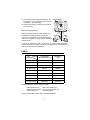
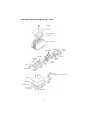
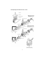
ALITA® LINEAR AIR COMPRESSORS
OPERATION & MAINTENANCE MANUAL
MODELS:
AL-30, AL-40, AL-60, AL-80
AL-100, AL-120, AL-150, AL-200
AL-250, AL-300, AL-350, AL-400
ALITA INDUSTRIES, INC.
Efficient and Reliable Air Moving Products
ALModel Number
DateCode / Serial Number
Date of Purchase
Phone
Dealer
Dealer Address
Remember to mail in your
Warranty Registration
Alita Industries has made every effort to ensure the correctness and completeness of the
materials in this document. Alita Industries shall not be liable for errors contained herein.
The information in this document is subject to changes without notice. Alita Industries
shall not be liable for any errors or for incidental or consequential damages in connection
with the furnishing, performance, or use of this document. Alita Industries makes no
warranty of any kind with regard to this material, including, but not limited to, the implied
warranties of merchantability and fitness for a particular purpose.
Revision F, May 2010
Copyright © 2010, Alita Industries, Inc. All rights reserved.
-1-
LIMITED WARRANTY
ALITA warrants to the original retail consumer purchaser (“Customer”) that the ALITA product, when properly
installed and operated under normal conditions of use, will be free from defects in materials and workmanship
for a period of three (3) years from the date of purchase from ALITA or an authorized ALITA representative.
This warranty applies only to ALITA products installed in the United States of America and Canada. Customer
is responsible for registration of product warranty and maintaining a dated proof of purchase, and such
registration and proof shall be used to determine warranty eligibility.
ALITA Limited Warranty covers only those defects which arise as a result of normal use of the product and do
not apply to any: (a) defect or malfunctions resulting from failure to properly install, operate or maintain the
ALITA product in accordance with printed instructions provided; (b) failures resulting from abuse, accident or
negligence; (c) ALITA product which is not installed in accordance with applicable local codes, ordinances
and good trade practices; (d) operation outside the ALITA product’s specifications or used for purposes other
than for what it was designed and manufactured; (e) improper or inadequate maintenance or modification,
and (f) damage due to shipment, lightning, natural disaster, earthquake, fire, flood, force majeure or
circumstances beyond the control of ALITA.
If within the duration of Limited Warranty, the ALITA product shall prove to be defective due to defective
materials or workmanship of ALITA, ALITA shall either repair or replace the defective product, at ALITA’s
option. ALITA shall have no obligation to repair or replace until the Customer returns the defective product,
together with dated proof of purchase and written notice of alleged defect to ALITA. Customer may be
required at ALITA’s request to verify that he or she is the original purchaser of the ALITA product and the
ALITA product has been installed and operated in accordance with ALITA’s instructions. Any replacement
product may be either new or like-new, provided that it has functionality at least equal to that of the product
being replaced. No requests for service under this warranty will be accepted if received more than 30 days
after the term of the warranty.
ALITA shall be liable only for the cost of the replacement part, or the repair of any defective part. Customer
shall be responsible for labor, cost of removal and installation at Customer’s premises, transportation and
insurance cost to and from ALITA, and any other incidental costs.
Correction of defects, in the manner and for the duration of the warranty described in this Limited Warranty,
shall constitute complete fulfillment of all liabilities and responsibilities of ALITA to the Customer with respect
to the product, and shall constitute full satisfaction of all claims, whether based on contract, negligence, strict
liability or otherwise.
Except for the obligations specifically set forth in this Limited Warranty, in no event shall ALITA be liable for
direct, indirect, special, incidental, or consequential damages, whether based on contract, tort, or any other
legal theory and whether advised of the possibility of such damages.
ALITA disclaims all other warranties with respect to ALITA product, whether implied, and specifically disclaim
the implied warranties or conditions or merchantability, satisfactory quality, fitness of a particular purpose.
Unauthorized extensions of warranties by the customer shall remain customer’s responsibility.
ALITA reserves the right to change or improve its products or any portions thereof without being obligated to
provide such a change or improvement for units sold and/or shipped prior to such a change or improvement.
The limited warranties described herein shall be the sole and exclusive remedy available to the Customer.
This warranty is void if the ALITA product has been improperly used, mishandled, disassembled or modified.
Customer is responsible for determining the suitability of ALITA products for customer’s use or resale or for
incorporating them into objects or applications which customer designs, assembles, constructs or
manufactures.
-2-
SAFETY INSTRUCTIONS
Special care should be taken when operating an electrical device. To avoid
serious or fatal personal injury or major property damage, read and follow all
safety instructions in manual and on pump.
WARNINGS
•
•
•
•
DO NOT operate pump in the vicinity of explosive or flammable materials,
liquids or gases.
DO NOT operate pump if it has being inundated by water.
DO NOT operate pump if it has a damaged cord or plug, if it is not working
properly, or if it has been damaged or dropped.
To avoid Electric Shock resulting from water back-siphoning, pump must be
installed above the water level.
CAUTIONS
•
•
•
•
•
•
Operate the pump only in fully assembled state.
This product is designed to pump air only. Do not attempt to pump any
other gases or fluids. Any airborne contaminants must be filtered out.
Do not lubricate this oil-less air pump. No parts on this pump have oil or
require lubrication. Avoid close proximity to products that may release oil or
gasoline vapors.
Connect the pump only to an outlet with GFCI (see Electrical Safety).
Reduce the risk of bursting by only use air handling devices rated for
pressure no less than 8 psi or 55 kPa.
Keep power cable away from heated surfaces and pedestrian traffic.
INSTALLATION and OPERATION
Place the pump upright securely on a dry and stable surface that is easily
accessible for inspection. Avoid location or elevation that will be inundated by
water. For aeration applications, the pump must be installed above the water
surface level.
PROPER VENTILATION
Allow ample clearance around the pump for free air circulation. Good
ventilation ensures proper heat dissipation which lowers internal operating
temperature and prevents thermal stress to key components.
When pump is to be placed under a protective enclosure, avoid designs that
can cause thermal insulation. Install forced ventilation system to promote air
circulation under the enclosure and improve pump reliability. Certain indoor
installation may also require forced ventilation when the forces of air pressure
and gravity are not enough to circulate air through a room or building.
-3-
For outdoor installations, shaded area that shelters from excessive weathering
is ideal. Do not allow pump to swelter under intense sun and avoid places with
excessive dust or debris.
The ambient operating temperature for this pump is between 5°C (41°F) and
40°C (104°F). Operation of pump in temperature outside of the recommended
temperature range may result in malfunction or severely shorten the pump life.
PIPE SIZING
Utilize air tubing or pipes that are equal or larger than the pump discharge port.
Matching pipe fittings should be used to reduce frictional losses. Incorrect pipe
sizing can cause unsatisfactory performance.
When selecting or constructing an air manifold, the number of outlet fittings and
their orifice size must be considered carefully to minimize frictional losses. Do
not block or restrict pump discharge for extended periods. Install a bleed valve
to vent any excess air volume and attach an air diffuser as silencer or muffler.
ELECTRICAL SAFETY
Form a drip loop with the power cord before connecting to the electrical
terminal. Drip loops can prevent water from traveling down the cord and
entering the power connection.
In the event of an electrical short circuit, grounding reduces the risk of electric
shock by providing an escape wire for the electric current. This pump is
equipped with a cord having a grounding wire with an appropriate grounding
plug. The plug must be plugged into an electrical terminal that is properly
installed and grounded in accordance with all local codes and ordinances. Do
not modify the plug provided; if it does not fit the outlet, have the proper outlet
installed by a qualified electrician.
Connect the pump only to a terminal with Ground
Fault Circuit Interrupter (GFCI) installed. This
device should serve to interrupt the flow of electric
current in the event of ground faults (electrical
current that unintentionally flows to ground). Check
proper operation of GFCI every month, and replace
faulty GFCI immediately.
Electrical Outlet with GFCI
Plug with
grounding pin
EXTENSION CORD
If an extension cord is required, use only a 3-wire extension cord that has a 3blade grounding plug, and a 3-slot receptacle that accepts the plug on the
pump. Be sure to use one heavy enough to carry the current the pump draws.
For lengths less than 50 feet, No. 16/3 AWG extension cord shall be used. An
undersized cord can result in a drop in line voltage, loss of power and
overheating. Replace any damaged extension cord immediately.
-4-
MAINTENANCE INSTRUCTIONS
Periodic pump maintenance is required for reliable continuous operation. Any
maintenance of the pump other than those described herein this manual must
be performed by an authorized service facility.
CAUTION: Always turn off the power and unplug from electrical terminal before
any maintenance. Failure to observe this precaution can result in serious
accident.
AIR FILTER
Air filter pad under the filter cover should be cleaned every 3 to 6 months.
Wash the filter pad gently in mild, soapy water then rinse thoroughly. Allow
filter pad to dry completely before reinstalling.
DIAPHRAGM MODULES
Diaphragm module replacement is typically recommended for every 24 months
of operation. Replacement cycle may differ from application to application, it is
prudent to perform the replacement before any actual diaphragm failure.
Diaphragm Replacement Kit (DRK) can be ordered from Alita Industries or
authorized Alita representative.
Diaphragm Module Replacement
1. Set pump upside down (remove filter cover for stability if required), unscrew
and remove all upper housing screws. Then return pump to upright position
and lift away upper housing. Number of housing screws: AL-30~80 (4x),
AL-100~200 (6x), AL-250~400 (12x)
2. Detach the L-tube from discharge port of each diaphragm housing.
3. Select a diaphragm housing on core frame, remove its 4 corner screws,
then pull housing away. Proceed to remove the hex nut and washer from
center of the diaphragm then pull and slide the entire diaphragm block away
from magnetic rod and core frame.
4. Select a new diaphragm block from the DRK, align shape with core frame
and magnetic rod then slide over the rod screw. Secure assembly firmly with
washer and hex nut. Apply 1 to 2 drops of removable grade threadlocker
between the hex nut and protruded rod screw.
5. Install new diaphragm housing then secure with 4 corner screws.
6. Attach L-tube to the discharge port of the new diaphragm housing then
secure with silicone band or wire hose clamp.
7. Repeat step #3 through #6 on opposite side.
IMPORTANT: Do not mix old and new parts. For reliable operation, always
replace both diaphragm modules in the pump at the same time.
8. Inspect the position of magnetic rod from the top. Magnetic rod should be
centered between the electromagnets. No contact should exist between the
magnetic rod and the two electromagnets.
-5-
9. If the pump includes a protective switch on top
of the pump core, rotate and reset the switch to
ON position. (See illustration)
10. Install upper housing, and secure firmly with all
housing screws.
Protective Switch
Magnetic Rod Replacement
Magnetic Rod between the two diaphragms may
get damaged if diaphragm failure has already
occurred. If the magnetic rod has suffer damages,
order a new magnetic rod along with the diaphragm
replacement kit.
In case of unusual noise or odor from the pump, turn off the power immediately,
consult the maintenance guide, or contact your nearest pump representative or
Alita service department for assistance.
PARTS
PARTS
DIAPHRAGM
REPLACEMENT KIT
MAGNETIC
ROD
AL-30
DRK40
MR30
AL-40
DRK40
MR40
AL-60
DRK60
MR60
AL-80, AL-100
DRK120
MR100
AL-120
DRK120
MR120
AL-150, AL-200
DKR200
MR200
AL-250
DRK120x2
MR120x2
AL-300
DRK200x2
MR200x2
AL-350, AL-400
DRK200x2
MR200x2
MODEL
Standard Diaphragm Replacement Kit includes:
Diaphragm Block (2x)
Diaphragm Housing (2x)
Air Filter Pad (1x)
Semi Cover Packing (1x)
Hex Nut & (2x) Washer (2x)
Instruction Sheet
For parts identification, please refer to Assembly Diagrams.
-6-
Assembly Diagram for Models AL-40 ~ AL-80
Cover Bolt
Filter Cover
Semi Cover Packing
Air Filter Pad
Upper Pump Housing
Diaphragm
Housing
Electromagnets
Hex Nut
Diaphragm
Diaphragm
Frame
Diaphragm
Block
Hex Nut
Magnetic
Rod
L-tube
Core
Frame
Diaphragm
Block
Silicone Band
Diaphragm
Housing
Power Plug
(Plug type varies from region to region)
Base Plate
Base Packing
Lower Pump Housing
Pump Housing
Corner Screws
Rubber Feet
-7-
Assembly Diagram for Models AL-100 ~ AL-400
Cover Bolt
Filter Cover
Models AL-100~120
AL-250 Dual Core
Semi Cover Packing
Air Filter Pad
Protective Switch
Upper Pump
Housing
Hex Nut
Diaphragm
Magnetic Rod
Diaphragm Frame
Diaphragm Housing
Models AL-150~200
AL-300~400 Dual Core
Core Frame
Diaphragm Frame
Diaphragm
Protective Switch
Hex Nut
L-tube
Hex Nut
Diaphragm
Magnetic Rod
Diaphragm Frame
Diaphragm Housing
Core Frame
Diaphragm Frame
Diaphragm
Hex Nut
L-tube
Base Plate, Power Plug and
Lower Pump Housing Assembly
-8-
TROUBLESHOOTING GUIDE
Pump does not start
•
•
•
Poor electrical connection: Plug the power plug firmly into AC outlet.
Power cord damage: Contact ALITA for repair service.
GFCI tripped: Check for moisture on plug or water inside the pump.
Replace faulty GFCI and/or try another GFCI protected AC outlet.
There exist a high humming or hissing noise
•
•
High backpressure: Reduce pressure load or bleed off excess air flow.
Poor air distribution lines: Re-configure or resize pipe lines and fittings,
use sound dampening materials, make firm and stable connections.
Pump stops intermittently
•
High operating temperature: Follow Proper Ventilation instructions on
this manual. Allow thermal protection circuit to reset after cooling.
Reduced flow rate or performance (after a period of usage)
•
•
•
•
Faulty air distribution medium: Replace clogged or damaged air line,
clean air control valves or release bends in flexible tubing.
Pump intake blocked: Remove blockage from pump intake.
Fouled air diffusers: Replace or clean air diffuser thoroughly.
Worn diaphragms: Replace aged or damaged diaphragm modules.
See Maintenance Instructions.
Pump stops and will not start (after a period of usage)
•
•
Diaphragm failure, magnetic rod adhere to electromagnet: Open pump
for inspection. Check for any damage to magnetic rod. Contact ALITA
for assistance and procure replacement parts.
For models AL-100~400 and certain models of AL-60/80
Protective Switch activated: Procure Diaphragm Replacement Kit for
maintenance. Follow instructions #1, #9 and #10 on Diaphragm Module
Replacement Procedure to reset Protective Switch.
Pump produces an abnormal noise (after a period of usage)
•
Diaphragm failure: Stop pump operation immediately. Open pump for
inspection. Check for any damage to magnetic rod. Contact ALITA for
assistance and procure replacement parts.
If none of the prescribed solution can help you resolve your pump problem,
contact ALITA for repair service instructions. DO NOT ATTEMPT to repair the
pump on your own.
-9-
For repair or service, contact your Alita representative or Alita Industries first for
instructions and to receive an authorization number prior to sending of the
pump. Alita Industries will not be responsible for any lost or misdirected
package.
When sending a pump for service or repair, please include the following:
1.
2.
3.
4.
5.
Dated proof of purchase.
Legible contact information and return address
i.e.
Name
Address
Telephone / mobile number
Fax number
Email address
etc.
Description of the pump application and installation setup.
(Include drawings or photographs if possible.)
Summary of the operating conditions and history.
Detailed description of the problems.
Every effort has been made to ensure the completeness and accuracy of this document.
Please contact Alita Industries if you notice any possible error or omission.
- 10 -
ALITA INDUSTRIES, INC.
PO Box 660923, Arcadia, CA 91066-0923, USA
Phone: (626) 962-2116 On-Line: www.alita.com E-mail: [email protected]