1
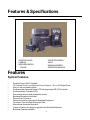
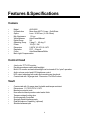
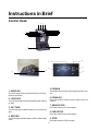
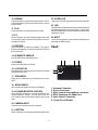
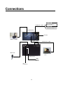
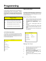
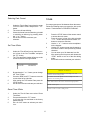
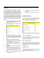
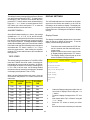
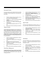
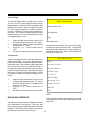
PROSECUTOR 2000
(4 inch LCD)
TRUNK MOUNTED UNIT
Operation Manual
Please Read
CAUTION!
RISK OF ELECTRICAL SHOCK!
DO NOT OPEN!
CAUTION! TO PREVENT ELECTRIC SHOCK, DO NOT
REMOVE COVER. NO USER SERVICEABLE PARTS
INSIDE. REFER SERVICING TO QUALIFIED PERSONNEL.
WARNING: TO REDUCE THE RISK OF FIRE OR ELECTRIC SHOCK,
DO NOT EXPOSE THIS APPLIANCE TO RAIN OR MOISTURE.
DANGEROUS HIGH VOLTAGE IS PRESENT INSIDE THE ENCLOSURE. DO NOT OPEN THE CABINET. REFER SERVICING TO QUALIFIED PERSONAL ONLY.
CAUTIONS: TO PREVENT ELECTRIC SHOCK, MATCH WIDE BLADE
OF PLUG TO WIDE SLOT, FULLY INSERT.
NOTE:
This equipment has been tested and found to comply with the
limits for class A digital device, pursuant of part 15 of the FCC
Rules. These limits are designed reasonable protection against
harmful interference when the equipment is operated in a commercial environment. This equipment generates, uses, and can
radiate radio frequency energy and, if not installed and used in
accordance with the instructions manual, may cause the harmful
interference to radio communications. Operations of this equipment in a residential area is likely to cause harmful interference in
which case the user will be required to correct the interference at
his own expense.
USER-INSTALLER CAUTIONS: YOUR AUTHORITY TO OPERATE THIS FCC VERIFIED EQUIPMENT COULD BE VOIDED IF YOU MAKE CHANGES OR MODIFICATIONS NOT EXPRESSLY
APPROVED BY THIS PARTY RESPONSIBLE FOR COMPLIANCE TO PART 15 OF THE FCC
RULES.
COPYRIGHT © PROTEX INC. 1998-2000
Table of Contents
FOREWORD.......................................................................4
FEATURE & SPECIFICATION........................ .................... 5
INSTRUCTION IN BRIEF.................................................... 8
INSTALLATION.................................................................. 11
CONNECTIONS.................................................................. 14
BASIC OPERATIONS......................................................... 15
PROGRAMMING................................................................ 16
WARRANTY INFORMATION.............................................. 23
3
Foreword
We thank you for your purchase of the PROSECUTOR 2000 SYSTEM (Trunk Mounted Unit).
You have purchased a high quality system that will provide you with many years of trouble free
service.
Should you have any question about the system, or any problems, please call (800)- 482-9211
or fax (281)-443-9079. We service all components of the system in house as well as through our
ever-growing Dealer Base
This guide will provide the user with enough information to operate the PROSECUTOR 2000
properly and effectively. As you read through this guide, if you have any questions, ideas, or
suggestions about the system or the guide itself, please feel free to call us at your convenience.
Thank You
ProTex, Inc.
1617 East Richey Road.
Houston, Texas 77073-3512
4
Features & Specifications
CONTROL HEAD
CAMERA
WIRELESS MICROPHONE
VIDEO RECORDER
VAULT
WIRING HARNESS
OPERATION MANUAL
Features
System Features
•
•
•
•
•
•
•
•
•
•
•
•
•
Smallest Trunk VAULT Available
16 X optical Zoom Low Light Auto Focus Camera, 1.0 Lux, 8X Digital Zoom
Easy to use over head controls
Programmable Industrial Grade VCR with proprietary RS-232 Controller
Environmentally Controlled VCR .
Record activation by body transmitter control
Backseat Microphone Included
Record Over Protection
Radar Gun Interface included as Standard Equipment
On-screen Time and Date Stamp with Title
Manual and Automatic Operation
Camera Position can easily be adjusted via Windshield Bracket
Backseat Camera available
5
Features & Specifications
Camera
•
•
•
•
•
•
•
•
•
•
•
•
Model
AVE-8002
Hi-Resolution
More than 450 TV Lines – Solid State
Optics
Lens - X16 Zoom (f=3.9-63mm)
Min. Illuminance
1.0 Lux
White Balance
Auto/Preset/Manual
Digital Zoom
X8
Operating Temp.
0 deg.C - 40 deg. C
Power
12V(2V / 4W
Dimension
2.65”W X 2.56”H X 4.4”D
Regulation
FCC – Class A
Focus
Auto/Near/Manual/Wide
Back Light Compensation
Control Head
•
•
•
•
•
•
4 inch color TFT LCD monitor.
Durable membrane switch with backlight.
Both LCD monitor and switch backlight can be turned off for “quiet” operation.
Audio volume control and LCD brightness control
LED output indicating both audio and recording are functional.
Constructed with 18 gauge steel. Dimension 11x6.25x3 inches.
Vault
•
•
•
•
•
•
•
•
•
Constructed with 14-gauge steel, lockable and tamper resistant
Dimensions: 11.5”W X 6.5”H X 16”D
Bracket mounted in trunk
Non-reflective black powder coated matte finish
Tamper resistant locking door
Environmentally Controlled
Specialty Radar Interface ready
Dual Microphone Capability (optional)
Shielded antenna input
6
Features & Specifications
VCR
•
•
•
•
•
•
•
•
•
•
•
•
Industrial grade VHS format Mobile recorder
Operating Voltage
8.5V to 15V DC / 15W
Operating Temp
0 to 40 (C (32 to 108 (F)
Recording Method
Dual-head
Recording time
8 hour (with T-160 tape)
FFW/REW Time
< 5 minutes using T-120 tape.
Horizontal Resolution
> 250 lines
On-screen display
Time/date, Title, 3 indicators, tape time, VCR status, Radar
Gun Readout and programming menu when selected
RS-232 interface to most Radar and Laser speed measuring devices
Automatic search for the last recorded portion of tape before recording
Recording can be started with Audio transmitter, Siren signal, or Light signal
Recording can be activated with Overhead Controls
Audio Transmitter and Receiver
•
•
•
•
•
•
•
•
•
Transmitter dimension 3.5” X 2.5” X 1”
Lavaliere wireless microphone system made by Shure
Frequencies in VHF range – currently 8
Working range - 300ft
Battery life – 18 to 20 hour with 9V alkaline battery
Wind-screen and tie clip
Holster – forward cantered; optional patent leather or basket weave
Audio receiver mounted inside the vault
Shielded antenna mounted on trunk– ¼ wave whip design
Wiring Harness
•
•
•
•
Control cable
Power cable
Radar interface
Antenna
25-conductor shielded with DB-25 connector
16 gauge stranded – fused to battery
2-conductor shielded with DB-9 connector (optional)
Shielded 75 coax terminated via BNC to chassis of vault
7
Instructions in Brief
Control Head
1
9 6
10
13
14
2 3
4
78
11
12
15
5
16
17
22
21
23
20
19
24
18
5. ZOOM IN
1. AUDIO ON
Press this button to Zoom In the image of the front camera.
The Audio Light will be ON when the wire less microphone is turned ON.
6. ZOOM OUT
2. LOW TAPE
Press this button to Zoom Out the image of the front
camera.
The Low Tape Light is the warning that the tape is about
to END.
7. NEAR FOCUS
3. OUT TAPE
Press this button to focus the objects.
The Out Tape light indicates that this is the end of the
tape.
8. FAR FOCUS
Press this button to focus the objects.
4. RECORD
The Record light indicates that the VCR is in Recording
mode.
9. STOP
8
Press this button to STOP the tape.
10. REWIND
Press this button to Rewind the tape while the VCR is
in the stop mode or Press in Play mode to do a reverse
picture search.
22. INTERFACE
connector for interfacing with siren and white light bar.
23. LED
This LED will turn ON when the VCR receives the Record
and Audio signal from the control head. This will help
the officer determine the control head record status from
outside the vehicle.
11. PLAY
Press this button to start the play back mode.
12. F.F.
Press this button to Fast Forward the tape while VCR
is in the stop mode or Press in Play mode to do a forward picture search.
13. RECORD
Press this button to start the recording. The light on
the Record button (No. 4) will be on when the VCR is in
the record mode.
24. BSET
You can select the front or rear camera/ microphone by
switching the BSET switch.
Vault
14. IR REMOTE SENSOR
Point the IR remote toward the sensor.
1
3
4
5
15. POWER
Press to turn the power on and off.
16. LCD DISPLAY
This Displays the live images of the camera or recorded
images off of the VCR.
6
2
17. SPEAKERS
Plays the live sound from the microphone or from the
VCR.
18. BRIGHTNESS
This controls the brightness of the LCD display.
19. VOLUME/ MONITOR CONTROL
Move this knob clockwise or counter clockwise to control the Speaker’s volume. You can also control the
LCD monitor and control head’s display light by this
knob.
20. CAMERA INPUT
Connect the front camera to this connector.
21. CONTROL
DB-25 connector for control head interfacing with vault.
9
1. Antenna Connector
2. Power Connector
3. Rear Camera & microphone connector
4. DB-9 Connector for Radar Gun
5. Vault Control Connector
6. 3 Amp Circuit Breaker
IR Remote Control
PAUSE/STILL
POWER
Press during recording to pause recording. Press during the playback to freeze the picture.
REC
PAUSE/
STILL
Caution: If this button is held for 6 seconds then it will
master reset the VCR and clear all the programming to
factory default.
STOP
SP/EP
SP/EP
Don’t use this button. Recording speed can only be set
in the on screen programming mode.
PLAY
REW
F.F
STOP
TRACKING
Press this button to stop a running tape. Alternatively
press and hold that button for 3 to 5 seconds to access
the programming mode.
PLAY
Press this button to start the play back mode.
REW
Press to rewind the tape during the stop mode and to
reverse picture search in play back mode.
FAST FORWARD
Press to fast forward the tape during the stop mode,
and forward picture search in the play back mode. In
programming mode use this button to access the menu
selection.
TRACKING
Use (+) or (-) button to manually adjust the tracking of
the picture. In the programming mode use these buttons to move the cursor upward or downward.
POWER
Don’t use this button. The VCR power is controlled by
the internal microprocessor. The VCR will automatically power up when 12VDC is applied to the VCR.
REC
Press these two (2) buttons simultaneously to manually start recording.
10
Installation
To properly install the Prosecutor 2000 System, please read and perform each of the following steps in order.
Preparation
Disconnect the car battery cables. Remove the lower half of the rear seat. Remove the kick panel and trim strips on
front and rear passenger side of the car. Remove or loosen the lower half of the trim on the door post between the front
and the rear door enough to get cables under.
Camera Mount
Remove the mount foot from the camera mount. If you are using a windshield mounted camera, mount the foot to the
window by following the directions on the included adhesive package, making sure to follow the instructions exactly.
If you are not mounting the camera to the windshield, follow the directions on the adhesive package and mount the foot
in the desired location, paying special attention not to obstruct air bag deployment. Allow adhesive to set until the end
of the installation before mounting the camera.
LED
The LED wire connection will hook into the rear of the Control head. Place the LED cable somewhere on the front
dashboard, making the LED end visible outside the front windshield of the vehicle. (On the driver side of the
windshield is recommended. This way the cable can be placed up the side panel and run across the edge of the
headliner to the rear connection of the control head.)
Trunk Unit Mount
Place the unit in the desired location of the trunk. Make sure that the unit can be unlocked and opened easily, and
tapes can be loaded and ejected conveniently.
Checking accessibility of vault and
tape insertion
Unlock the unit and remove the base plate. Pay attention to the location of the gas tank. If this is a Crown Victoria
installation, use the mounting brackets.
Note: If the unit is going to be mounted on the shelf next to the spare tire, special care must be taken to avoid drilling
into the gas tank and the mounting brackets must be used.
Assembly of the mounting brackets
to the base plate of vault
Mounting of the mounting brackets
with base plate of vault attached
11
Completed assembly of brackets
and base plate of vault
Trunk Mounting Cont.
Connect the Control Console cable , rear Camera and
Mic cable, Antenna cable and the Power cable to the
rear of the vault. Bundle the cables to create a service
loop so that the vault can easily be unlocked, removed
from the base plate and cables disconnected.
Attaching the cables to the
rear of the vault.
Control Console
Remove the control head mounting plate from the control console (4 screws on front). Remove the sun visors inner
attachments (closest to the rear view mirror).Position the control
mounting plate between the sun visors such that when the control
box is attached, the monitor can be viewed from driver’s position.
Align the hole over the sun visor’s inner attachment holes and reinstall the sun visor attachments, making sure the control head mounting plate is captured by the attachments. If additional support is
desired (requires making holes in headliner), 3/4 inch self-drilling
screws can be used to attach the mounting plate to the secondary
metal under the headliner. Wait to mount the control box until the
end of the installation.
Note: If you have a ticket light (round light) added to your vehicle, you
have to use the ticket light adapter.
Attaching the Control head mounting plate
between the sun visors.
To determine wether or not you need the ticket light adapter, position the control box behind the light. You should
have at least 2 inches between the control box and window, but still be able to get to the monitor controls on top of the
control box. Most Ford Crown Victoria’s will not need this, most Chevy Caprices will.
Antenna Mount
This is a common lip antenna. Position the antenna at the desired location on top of the trunk. For mounting see the
instructions enclosed with the antenna.
Note: If the Radio Frequency Interface is significant, a permanent 1/4 inch wave VHF antenna may be needed to
mount through the fender of trunk.
Rear Camera & Microphone
Position the camera and microphone to the desired location at the rear of the vehicle. For mounting, see the
instructions enclosed with the Rear Camera.
Interface Cable
This is the gray cable with a 4-pin connector on one end and the orange, black, blue, and white wires on the other end.
Route the interface cable from the control head to the fuse box. Start at the center of the headliner, to the driver side
of the central cable, leaving about 4 inches of the 4 pin plug end of the cable hanging down. Route across, under edge
of the headliner, down the door to the fuse box. Attach the orange wire to switched 12 V. Extend white wire to the
light box wire that gets 12 V when the overhead lights are activated. Attach the blue wire (+) and the black wire () to the siren. If the siren is AC instead of DC, you can use the same connections.
Note: For AC-The Blue wire is Hot, the Black wire is Neutral.
DB-25 Control Cable
This is the 25 foot DB-25 male to DB-25 male cable. Connect one side of the cable to the control head and other to
the vault. Route the cable through the backseat to the front of the car, up the front door post, along the front edge of
the headliner, to the middle of car. Leave about 4 inches hanging from the headliner. (Pictures of cables being routed
located on next page with Power Cable routing)
12
Power Cable
This is the gray cable with red and black wires on one end and a 4 pin connector on the other end. Verify the 4-pin
connector is connected to the vault in the trunk. Route the cable through the rear seat panel, under the back seat and
carpet, to the battery area of the car (routing through the firewall to the battery is preferred). Secure the red wire to +12
V (through the firewall to the battery is the best way). Connect the black wire to chassis ground.
View of DB-25 and Power Cables coming
from trunk, positioned behind the rear
passenger side seat, heading toward
front passenger seat. Note: cables go
under carpet.
View of DB-25 located on front
passenger side, under trim, heading
upward toward headliner. Note: Power
Cable will go through firewall towards
battery.
View of DB-25 Cable, under headliner,
heading toward control console.
Final Assembly
Attach the front camera to the camera mount and attach the camera cable to the control box. Also, attach the control
cable , interface cable and LED cable to the control box. Securing the cables out of sight in the headliner, mount the
control box to the back plate using the 2 screws that were previously removed. Secure vault to base plate and lock in
place. Verify cables are properly routed and are not pinched or in a bind.
View of camera being attached to
windshield mount. Note: Cable of
camera goes upwards into headliner.
View of DB-25, Interface, LED,
Camera and Power Cables being
connected to Control Console.
View of control console being mounted with
wires already attached to connections
Reinstall previously removed panel, trim, seats and other hardware. Reconnect car battery cables.
Power up the system
Attach completing the installation assembly, turn on the volume/monitor control switch. If the light on the POWER
does not turn on, check all the system connections and fuse in the power cable near the car battery. If the “POWER”
light is illuminated on the control console, the system can be turned on by using one of the following methods:
Control console activation - Press the “POWER” button on the control console.
Microphone activation - Place the remote microphone transmitter power switch in the “ON” position. The green LED
will illuminate on the microphone transmitter and the system will be powered up.
Power up the wireless receiver
The audio receiver powers up automatically when the power cable is connected to the battery and the control cable is
connected to the control console.
13
Connections
BLUE SIREN (+)
INTERFACE CABLE
BLACK SIREN (-)
WHITE LIGHTBAR +12 V
ORANGE IGNITION +12 V
CONTROL HEAD
(TO LED)
FRONT CAMERA
CONTROL CABLE
RADAR GUN CABLE
REAR MIC
RADAR
GUN
IN TRUNK UNIT
RED
BLACK
(TO
ANTENNA)
14
Basic Operations
POWER UP THE SYSTEM
Complete the installation of the “In Trunk system” as describe in the previous section. Turn On the volume/monitor control switch. If the light on the Power does not turn
on, check all the system connections. If Light on the
POWER is on then you can turn on the system using one
of the following methods:
1. From Control Head:
Press the “POWER” button on the control head and it will
turn “ON” the system
2. Microphone Activation:
Place the Microphone/Transmitter power switch in the “ON”
position, the green LED will come on the Microphone/
Transmitter and the system will automatically turn on.
STOP RECORDING
Press the “STOP” button on the control head or press the
“STOP” button on the IR Remote control to terminate the
recording.
EJECTING THE TAPE
Press the Stop/Eject button on the VCR once to stop the
recording and press it again to eject the cassette. When
the cassette approaches the end of the tape, a “LOW
TAPE” light will illuminate on the control head. When the
end of the tape is reached, the control head will begin
“beeping”, and the “OUT TAPE” light will illuminate on the
control head. You can press the “STOP” button from the
control head, or use the IR Remote Control, or eject the
cassette from the VCR to stop the beeping. A “CASS
OUT” message will appear on the LCD display acknowledging that the Cassette is out of the VCR.
POWER UP THE WIRELESS RECEIVER
The audio receiver powers up automatically when the power
cable connects to the battery and the control cable connects with the control head.
Note:The wireless receiver consumes 140 mA of current.
We recommend to disconnect the Control cable from the
Control head if the vehicle is not used for more than a
week.
INSERT CASSETTE
First power up the system, then insert the tape into the
cassette compartment until the VCR pulls the cassette
in.
Note: Do not force the tape in the mechanism or this will
damage the VCR. If the input voltage is less than 12
VDC, then VCR will not accept the cassette.
START RECORDING
You can start recording by either pressing the control
head’s “RECORD” button or pressing the record buttons
on the IR remote control. When the VCR is in the Record
mode the light on the VCR’s RECORD button will be ON.
You can also program the VCR to power up in the Record
mode.
Note: See the Record Setting under the programming for
more details.
15
Programming
TIME & DATE SETUP
In this section we discuss some of the powerful programming features of the “in trunk system”. The programming mode can only be accessed by using the IR
remote control. The following table shows some of the
IR- Remote button functions used in the programming
mode.
An Internal clock generates the time and date that is
super imposed on the LCD display. After the clock is
set, the date and time modes are displayed on the monitor screen (live picture).
Display Time & Date on Screen
Things to Note:
1
“STOP”- Press and hold the remote control’s “Stop”
button for 5 seconds to access the mail menu
“F.F.”
- Press this button to enter or exit any selection
“+”
- Press this button to move the cursor up
“-”
- Press this button to move the cursor down
2
3
4
5
Under the “Display Time & Date” menu place
the cursor in front of T/D display and press the
“ F.F” button of the remote control.
Press the “+” or “-” button to select “ON” or
“OFF”.
Press the “F.F.” button again to make your
selection.
To exit out of the Display Time & Date, place
cursor in front of “Exit” and press the “F.F.”
button.
Exit out of all of the menus to activate above
your selection.
ACCESSING MAIN MENU
Time / Date
To access the on screen programming press the “STOP”
button of the remote control for about 5 seconds. The
following programming menu will be appear on the monitor of the control head LCD.
T/D Display
ON
Time Format
12 Hour
Date Format
MM/DD/YY
Set Time/Date
Reset Time/Date
M ain M enu
Exit
Set Time/Date
Titler
M essages
Selecting Time Format
Record Setting
Display Setting
1
Rader Gun Inteface
2
3
M aster Reset
Exit
4
5
16
Place the cursor in front of “Time Format” and
press and release the “F.F” button.
The cursor will start blinking.
Now push the “+” or “-” button to select either
the “12” or “24” time display modes.
After selecting the desired mode press and
release the “F.F.” button.
Exit all of the menus to activate your selection.
Selecting Date Format
TITLER
1
You can program up to a 20 character title on the screen.
Follow the following steps to program the title on the
screen. The default title is ”PROSECUTOR 2000”.
2
3
4
Under the “Time & Date” menu place the cursor
in front of “Date Format” and press the “ F.F”
button.
The cursor will start blinking.
Chose the format from the selection yy/mm/dd
or mm/dd/yy or dd/mm/yy by pressing either
the “+” or “-” button.
Exit of all the menus to activate your
selection.
1
2
3
Set Time & Date
1
2
4
Under the “Time & Date” menu, place the cursor in front of the “Set Time/Date” and press
the “F.F.” button.
The “Time and Date” window will pop up on the
screen as shown in the figure below.
1:11:37P
5
6
7
Press the “STOP” button of the remote control
to access the main menu.
Place the cursor in front of the title using the
“+” or “-” button then press and release “F.F.”
button to accept the selection.
Use the “+” or “-” button to select an alphanumeric character.
Use the “F.F.” button to enter next character or
use “REW” button to edit a previously entered
character.
You can enter up to 20 characters in a title.
After entering the title press and release the
“STOP” button to exit out of the title editing
mode.
Exit all of the menus to activate your selection.
1/01/98TH
TH IN G S TO K N O W
3
4
5
6
By pressing the “+” or “-” button you can change
the Time or Date.
Press the “REW” and “F.F.” button to move the
cursor either left or right side.
After setting the Time and/or Date press the
“STOP” button.
Exit all of the menus to activate your selection.
"- " b utto n mo ve s the a lp ha b e t in a sc e nd ing o rd e r a nd
nume ric s in d e sc e nd ing o rid e r.
"+ " b utto n mo ve s the a lp ha b e t in d e sc e nd ing o rd e r a nd
nume ric s in a sc e nd ing o rd e r.
"F.F." b utto n mo ve s the c urso r to w a rd the right p o sitio n.
":R EW " b a c k sp a c e .
"S TO P " Exits o ut o f the e d iting mo d e
Reset Time & Date
1
3
4
5
Under the Time & Date menu select “Reset
Time/Date”.
Press and release the “F.F.” button.
It will reset the time and date to the factory
default settings.
Exit all of the menus to activate your selection.
17
MESSAGES
The trunk system has two message inputs, each message can display up to 10 characters. These messages are activated on the LCD display when the “in
trunk system” gets a signal from the interface cable (if
siren or lights are on). See the Installation section for
the connections (pin-outs) of the interface cable. By
default the “SRN” message appears on the screen when
the siren is on. Similarly, the “LTS” message appears
on the screen when the lights are turned on. The message “Record” comes on when an input is received
(Lights or Sirens) by the VCR and the VCR begins recording.
1
2
13
14
RECORD SETTINGS
Access the sub menu of the Record Setting by placing
the arrow next to Record setting and press the “F.F.”
button. The following sub menu will appear:
Press and hold the “Stop” button of the IR remote control for 5 seconds and the main menu
will pop up on the screen.
Place the cursor in front of “Message” using
the “+” or “-” button.
Recording S etting
Recycle Rec
O FF
Rec- o ver P ro tect
O FF
O N
P o wer- up Reco rd
O FF
O N
Alarm Rec Dwell
3min
O N
Exit
S et M essage
M essage 1
M e s s a g e 1 R e c o rd
M essage 2
M e s s a g e 2 R e c o rd
M essage 3
M e s s a g e 3 R e c o rd
Enter message 2 the same way message 1
was entered.
Exit all of the menus to activate your selection.
E x it
3
4
5
6
7
8
9
10
11
12
To make a selection press the “F.F.” button,
and the above menu will pop up on the screen.
Place the cursor in front of the message that
you want to change and press the “F.F.” button.
A blinking cursor will appear the screen.
Enter the letter or numeric character, using the
“+” or “-” buttons.
After entering the first letter press the “F.F.” button to move the cursor to the next place.
Again use the “+” or “-” button to select the
next letter.
Repeat steps 6 to 8 until you enter the complete title.
After entering the title press the “Stop” button,
it will return you to the Message sub menu.
After entering the title, place the cursor in front
of Message “1 Record” and press the “F.F.” button.
Press the “+” or “-” buttons to turn the message
recording ON or OFF.
RECYCLE RECORD
If you turn on this feature, at the end of the tape, the
VCR will automatically rewind the tape and record over
previous recorded information.
REC OVER PROTECT
If you turn on this feature, the VCR will NOT record over
previous recorded information. Instead it will search the
tape to find the end of the recording and begin the new
recording there.
POWER-UP REC
If you turn on this feature, the VCR will begin recording
as soon as the VCR is powered up.
Note: A tape must be in the VCR to begin “Power-Up
Rec”.
18
The default for these 3 settings (Recycle Record, Record
over and Power-up Record) is “OFF”. To change any or
all settings to “ON”, place the arrow beside the item,
press the “F.F.” button, and the arrow will start blinking.
Press the “–” or “+” button to switch between ON or
OFF. Make your choice and press “F.F.” to save the
selection and return to the sub menu.
DISPLAY SETTINGS
The VCR adds alphanumeric information to the video
signal from the camera and sends it to the VCR for
recording or to the monitor to display. The display settings let you select the position, the gray scale and the
format of the text. Following are the options in display
settings.
ALM REC DWELL’s
Alarm Dwell’s default setting is 1 minute; the settings
available are: 0, 1, 2, 5, 10, 15, 20, and 30 minutes.
The setting you choose will be the minimum recording
time after the Alarm Record Signal goes from high to
low, or active to inactive. To change the default settings
of alarm Record Dwell, place your cursor in front of Alarm
Rec Dwell under the Record settings menu and press
and release the “F.F.” button. Use the “+” or “-” key to
select the required time. After making the selection
press the “F.F.” button and it will return you to the Record
settings menu.
Display Format
The display format displays alphanumeric information
either on the top or bottom of the screen. To set the
display use the following instructions.
1
From the remote control press the “STOP” button for 5 seconds, the main menu will pop up
on the screen.
Under the main menu move the cursor in front
of “Display Setting” and press the “F.F.” button.
The “Display Setting” menu will pop up on the
screen as shown in the figure below.
2
3
TAPE SPEED
D is p la y S e ttin g
The default setting for this feature is T120/EP in NTSC
mode and T180/SP in the PAL mode. Consult the following table for correct mode of recording. An EP setting will triple the number of minutes of recording time,
i.e. 3 x a 120 or 160 min. tape. An SP setting enables
the exact number of minutes of recording time, as stated
on the tape (usually labeled T120 or T160).
D is p la y F o r m a t
B o tto m
H o r izo n ta l P o s itio n
Ve r tic a l P o s itio n
G r a y S c a le / B a c k g r o u n d
V C R S ta tu s
When you are finished with the sub-menu, move the
arrow to EXIT and press the “F.F” button. to return to the
main menu.
I n p u t Vo lta g e
Te m p r a tu r e
E x it
TYPE
RECORDING
MODE
SYSTEM
RECORDING
TIME
T120
SP
NTSC
2 hrs
T120
EP
NTSC
6 hrs
T160
SP
NTSC
3 hrs
T160
EP
NTSC
8 hrs
5
T180
EP
NTSC
9 hrs
6
E180
SP
PAL
3 hrs
E180
LP
PAL
6 hrs
E240
SP
PAL
4 hrs
E240
LP
PAL
8 hrs
4
7
8
19
Under the Display setting menu place the cursor in front of “display Format” using the “+” or
“-” button.
To select a display format press the “F.F.” button.
Now choose either “Top” or “Bottom” using the
“+” or “-” button.
Press the “F.F.” button to chose your selection.
Exit all of the menus to activate your selection.
Horizontal Position
1
Horizontal position sets the alphanumeric text position
horizontally. Follow the steps below to set the Horizontal position.
1
2
3
4
5
6
2
3
4
Under the display setting menu place your cursor in front of “Horizontal Position”.
Press the “F.F.” button to select the horizontal
position.
A small box will pop up on the screen.
Press the “+” or “-” button to select the appropriate position.
After selecting the position press the “F.F” button
Exit all of the menus to activate your selection.
5
6
Tape Counter
The tape counter displays the time left to record . To
turn on the Tape counter follow the instructions below.
Vertical Position
1
Vertical position sets the alphanumeric text position vertically. If the Display Format is set on “TOP” then the
vertical position lets you choose the position from the
top of the screen to the middle of the screen. If the
display format is set to the bottom then the vertical
position can be moved from the middle of the screen to
the bottom of the screen. Follow the steps below to set
the vertical position.
2
3
1
2
3
4
5
6
Under the Display setting place the cursor in
front of gray scale/back ground color.
Press the “F.F.” button to select “gray scale/
background color”.
A small box will pop up on the screen.
Press the “+” or “-” button to select the appropriate gray scale or background color.
After selecting the gray scale or background
color press the “F.F.” button.
Exit all of the menus to activate your selection.
4
5
Under the Display setting place the cursor in
front of vertical position.
Press the “F.F.” button to select “vertical position”.
A small box will pop up on the screen.
Press the “+” or “-” button to select the appropriate vertical position.
After selecting the position press the “F.F.” button.
Exit all of the menus to activate your selection.
Under the Display setting place the cursor in
front of tape counter.
Press the “F.F.” button to select “Tape counter”.
Press the “+” or “-” button to turn the VCR Status either “ON” or “OFF”.
After making the selection press the “F.F.” button.
Exit all of the menus to activate the selection.
VCR Status
VCR Status displays all the VCR operating modes on
the screen. Follow the procedure below to turn the
VCR Status On/Off.
1
2
3
Gray Scale / Background
4
Gray Scale/ Background color sets the gray scale and
background color of the alphanumeric text on the display. Follow the procedure below to set the gray scale
or background color.
5
20
Under the Display setting place the cursor in
front of VCR Status.
Press the “F.F.” button to select “VCR Status”.
Press the “+” or “-” button to turn VCR Status
either “ON” or “OFF”.
After making the selection press the “F.F.” button again.
Exit all of the menus to activate the selection.
Input Voltage
Rader Gun Interface
The VCR can display the input voltage on the screen.
You can turn off or on the voltage message from the
display settings. A “LOW VOLTAGE” message will start
flashing on the screen if the input voltage is less than
9V. If the voltage is less than 9 V and the cassette is
out then a “CASS OUT” message will start flashing on
the screen. The VCR will not accept a tape if the input
voltage is less than 9V. Follow the steps below to turn
the voltage display on or off.
1
2
3
4
Select Rader Gun
Set Baudrate
Exit
Under the main menu place the cursor in front
of Display Setting and press the “F.F” button.
Now place the cursor in front of Input Voltage
and press the “F.F.” button.
Press the “+” or “-” button to select “ON” or
“OFF”.
Exit all of the menus to activate your selection.
Select Radar Gun
Select Radar Gun submenu lets you select the radar
gun that you want to use with the VCR. To access the
radar gun interface place cursor in front of Radar gun
interface and press the “F.F” button. The following menu
will pop up on the screen:
Temperature
S e le c t R a d e r G un
A built in temperature sensor tracks the internal temperature of the VCR . You can view the internal temperature by enabling the temperature display in the display setting menu. If the temperature goes higher than
90 F then the Fan Output is activated (active low). If
the temperature goes lower than 40 F then the Heater
output is activated (active low). If the temperature goes
lower than 32 F then the VCR will be turned off. Follow
the steps to enable the temperature display on the
screen.
N o ne
D e c a tur G e ne sys
D e c a tur H unte r
G o ld e n E a gle
LTI 2 0 .2 0
M P H P ytho n
1
2
3
4
Under the main menu place the cursor in front
of Display settings and press the “F.F.” button.
Place the cursor in front of Temperature and
press the “F.F” button.
Press the “+” or “-” button to select “ON” or
“OFF”.
Exit all of the menus to activate your selection.
M unic ip a l T S - 4
R a p id F ire P lus
RG2RS
E xit
NONE
RADAR GUN INTERFACE
This is the default setting, and the setting you should
leave it chosen you do not have a radar gun connected
to the VCR.
The radar gun interface submenu displays the choices
of the manufacture of the radar gun. This menu also
lets you set the baud rate between the interface and the
radar gun. The following menu will appear if you select
the radar gun interface from the main menu.
21
GENERIC
This accepts any RS-232 data and displays it on the
monitor. This can be from a computer, a BAC, or other
device with RS-232 communications.
DECATUR HUNTER, DECATUR GENESYS, GOLDEN
EAGLE, LTI 20.20,MPH PYTHON, MUNICIPAL , OR
RAPID FIRE PLUS
These are specific types of radar guns for which settings have been programmed into the VCR-322-Plus
RG2RS
This is American Video Equipment’s Radar Gun Interface, which, when installed with the VCR, will enable
the following radar guns to connect to the VCR: The
RG2RS must be purchased separately and is not included with the VCR-322-Plus.
ACM STALKER
Decatur HUNTER, GENESYS 1 & II
KUSTOM KR-10SP, TROOPER
MPH K-55
TARGETRON RAPID FIRE PLUS
BAUD RATE
Here you select the correct Baud Rate for your Radar
gun. The choices available are: 1200, 2400, 4800, &
9600.
MASTER RESET
Master Reset, resets all the programming to factory
default settings. Follow the steps below to do a Master
Reset.
1
Under the main menu place the cursor in front
of “ Master Reset”.
2
Press the “F.F.” button to choose the selection.
3
The master reset menu will pop up on the screen.
4
Use the “+” or “-” buttons to place the cursor in
front of “ Do Master Reset”
5
Press the “F.F.” button to perform a master reset on the VCR.
6
A copyright menu will pop up on the screen
notifying you that the VCR has been reset.
Warning: If you do a Master reset this will clear all
settings and exit the programing mode.
22
Warranty Information
The PROSECUTOR 2000 system is covered by a ONE YEAR Warranty for all parts and labor.
To obtain service, order parts, or accessories simply call Prosecutor of Texas between 8am5pm Central Standard Time at (800)-482-9211. Should you need any service for your system,
you will be given an RMA # with shipping instructions. You MUST have an RMA # on your
package before we can accept it.
We do repair work on an individual basis. If quote, for service, is less than $100, work will
automatically be performed. If quote, for service, is more than $100, we will contact and get
customer authorization, before any work will be performed.
Thank you for using Prosecutor 2000.
Protex, Inc.
1617 E. Richey Road.
Houston, Texas. 77073-3512
Phone: (800)-482-9211
Fax: (281)-443-9079
23
Protex, Inc.
1617 E. Richey Road.
Houston, Texas. 77073-3512
Phone: (281)-443-6962
Fax: (281)-443-9079