1
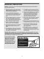
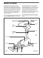
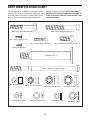
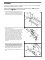
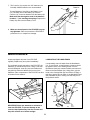
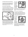
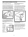
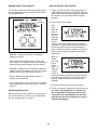
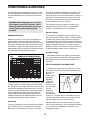
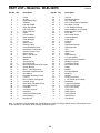
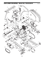
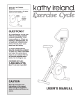
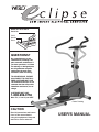
¨
Model No. WLEL36070
Serial No.
Serial
Number
Decal
QUESTIONS?
As a manufacturer, we are
committed to providing complete customer satisfaction. If
you have questions, or if there
are missing or damaged parts,
we will guarantee complete
satisfaction through direct
assistance from our factory.
TO AVOID DELAYS, PLEASE
CALL DIRECT TO OUR TOLLFREE CUSTOMER HOT LINE.
The trained technicians on our
customer hot line will provide
immediate assistance, free of
charge.
CUSTOMER HOT LINE:
1-800-999-3756
Mon.ÐFri., 6 a.m.Ð6 p.m. MST
Patent Pending
CAUTION
Read all precautions and instructions in this manual before
using this equipment. Keep this
manual for future reference.
USER'S MANUAL
¨
TABLE OF CONTENTS
IMPORTANT PRECAUTIONS . . . . . . . . . . . . . . . . . . . . . . . . . . . . . . . . . . . . . . . . . . . . . . . . . . . . . . . . . . . . .3
BEFORE YOU BEGIN . . . . . . . . . . . . . . . . . . . . . . . . . . . . . . . . . . . . . . . . . . . . . . . . . . . . . . . . . . . . . . . . . . .4
PART IDENTIFICATION CHART . . . . . . . . . . . . . . . . . . . . . . . . . . . . . . . . . . . . . . . . . . . . . . . . . . . . . . . . . . .5
ASSEMBLY . . . . . . . . . . . . . . . . . . . . . . . . . . . . . . . . . . . . . . . . . . . . . . . . . . . . . . . . . . . . . . . . . . . . . . . . . . .6
MAINTENANCE . . . . . . . . . . . . . . . . . . . . . . . . . . . . . . . . . . . . . . . . . . . . . . . . . . . . . . . . . . . . . . . . . . . . . . . .8
HOW TO USE THE WESLO¨ ECLIPSE . . . . . . . . . . . . . . . . . . . . . . . . . . . . . . . . . . . . . . . . . . . . . . . . . . . . .10
CONDITIONING GUIDELINES . . . . . . . . . . . . . . . . . . . . . . . . . . . . . . . . . . . . . . . . . . . . . . . . . . . . . . . . . . . .13
PART LIST . . . . . . . . . . . . . . . . . . . . . . . . . . . . . . . . . . . . . . . . . . . . . . . . . . . . . . . . . . . . . . . . . . . . . . . . . . .14
EXPLODED DRAWING . . . . . . . . . . . . . . . . . . . . . . . . . . . . . . . . . . . . . . . . . . . . . . . . . . . . . . . . . . . . . . . . .15
HOW TO ORDER REPLACEMENT PARTS . . . . . . . . . . . . . . . . . . . . . . . . . . . . . . . . . . . . . . . . . . .Back Cover
LIMITED WARRANTY . . . . . . . . . . . . . . . . . . . . . . . . . . . . . . . . . . . . . . . . . . . . . . . . . . . . . . . . . . .Back Cover
2
IMPORTANT PRECAUTIONS
WARNING: To reduce the risk of serious injury, read the following important precautions before
using the elliptical exerciser.
7. The elliptical exerciser should not be used
by persons weighing more than 250 pounds.
1. Read all instructions in this manual before
using the elliptical exerciser. Use the elliptical exerciser only as described.
8. Always pin the handlebars in the stationary
position and hold the handlebars when
mounting and dismounting the elliptical
exerciser. Always step onto and off the
pedal that is in the lowest position.
2. It is the responsibility of the owner to
ensure that all users of the elliptical exerciser are adequately informed of all precautions.
9. Each time you stop exercising on the elliptical exerciser, allow the pedals to slowly
come to a stop.
3. Place the elliptical exerciser on a level surface, with a mat beneath it to protect the
floor or carpet. Keep the elliptical exerciser
indoors, away from moisture and dust.
10. Always keep your back straight when using
the elliptical exerciser. Do not arch your back.
4. Inspect and tighten all parts regularly.
Replace any worn parts immediately.
11. If you feel pain or dizziness at any time
while exercising, stop immediately and
begin cooling down.
5. Keep children under the age of 12 and pets
away from the elliptical exerciser at all
times.
12. The elliptical exerciser is intended for inhome use only. Do not use the elliptical
exerciser in any commercial, rental, or institutional setting.
6. Wear appropriate clothing when exercising
on the elliptical exerciser. Always wear athletic shoes for foot protection.
WARNING: Before beginning this or any exercise program, consult your physician. This is especially important for persons over the age of 35 or persons with pre-existing health problems. Read
all instructions before using. ICON assumes no responsibility for personal injury or property damage sustained by or through the use of this product.
The decal shown at the right
has been placed on the elliptical exerciser. If the decal is
missing, or if it is not legible,
please call our Customer
Service Department toll-free at
1-800-999-3756 to order a free
replacement decal. Apply the
decal in the location shown.
Do not allow children on or
around machine.
Keep hands and feet away
from moving parts and contact
points.
Read owner's manual and
follow instructions.
3
BEFORE YOU BEGIN
Congratulations for selecting the revolutionary
WESLO¨ ECLIPSE low-impact elliptical exerciser.
The ECLIPSE is an incredibly smooth exerciser that
moves your feet in a natural elliptical path, minimizing
the impact to your knees and ankles. And the unique
ECLIPSE features adjustable resistance, dual-motion
handlebars, and a multi-mode exercise monitor to
help you get the most from your exercise. Welcome to
a whole new world of natural, elliptical-motion
exercise from WESLO.
tions after reading the manual, call our Customer
Service Department toll-free at 1-800-999-3756,
Monday through Friday, 6 a.m. until 6 p.m. Mountain
Time (excluding holidays). To help us assist you,
please note the product model number and serial
number before calling. The model number is
WLEL36070. The serial number can be found on a
decal attached to the ECLIPSE (see the front cover of
this manual for the location of the decal).
Before reading further, please look at the drawing
below and familiarize yourself with the parts that are
labeled.
For your benefit, read this manual carefully before
you use the WESLO¨ ECLIPSE. If you have ques-
Water Bottle Holder
(Bottle is not included)
Handlebar
Console
Pedal
Resistance
Knob
Lock Pin
Handlebar
Resistance
Knob
FRONT
Side Shields
Crank Arm
Stabilizer
BACK
RIGHT SIDE
Pedal Arm
Pedal
4
PART IDENTIFICATION CHART
Use the chart below to identify the small parts used in
assembly. The number in parenthesis below each part
is the key number of the part, from the PART LIST on
page 14. The number after the dash indicates the
quantity needed for assembly. Note: Some small
parts may have been pre-attached for shipping. If
a part is not in the parts bag, check to see if it has
been pre-attached.
M10 x 75mm Button Head Bolt (45)Ð2
M8 x 55mm Hex Head Bolt (63)Ð2
M4 x 16mm Screw (51)Ð6
M6 x 1Ó Hex Head Screw (27)Ð2
M10 x 25mm Button Head Screw (25)Ð3
Console Screw (33)Ð4
Pedal Bolt (36)Ð2
M10 x 150mm Carriage Bolt (32)Ð1
Wheel Spacer (79)Ð2
M8 Nylon Locknut (64)Ð2
1/4Ó Split Washer (62)Ð2
M10 Nylon Locknut (46)Ð2
M10 Split Washer (69)Ð3
5
1/2Ó Nylon Locknut (37)Ð2
M8 Washer (74)Ð2
Star Washer (29)Ð1
ASSEMBLY
Place all parts of the WESLO¨ ECLIPSE in a cleared area and remove the packing materials. Do not dispose
of the packing materials until assembly is completed.
In addition to the included allen wrench and flat wrench, a phillips screwdriver
adjustable wrenches
are required for assembly.
1. Position the Stabilizer (4) against the saddle on the
Frame (1). Insert two M10 x 75mm Button Head Bolts
(45) through the Frame and the Stabilizer. Tighten
M10 Nylon Locknuts (46) onto the Button Head Bolts.
and two
1
45
1
4
45
46
46
2. Attach a Pedal (9) to the Left Pedal Arm (7) with three
M4 x 16mm Screws (51).
2
9
If there is not a Wheel (60) on the Left Pedal Arm (7),
attach one in the following way: Hold a Wheel Cover
(59) inside of the bracket on the Left Pedal Arm (7).
Insert an M8 x 55mm Hex Head Bolt (63) with an M8
Washer (74) into one side of the bracket and the
Wheel Cover. Slide a Wheel Spacer (79), a Wheel
(60), and another Wheel Spacer onto the end of the
Bolt. Insert the Bolt through the other side of the
Wheel Cover and the bracket. Tighten an M8 Nylon
Locknut (64) with an M8 Washer (74) onto the Bolt.
7
Bracket
74 64
51
74
59
63
79
Assemble the Right Pedal Arm (not shown) in the
same way.
79
3. Insert a Pedal Bolt (36) through the bushings in the
Left Pedal Arm (7). Using the included flat wrench,
tighten the Pedal Bolt into the left arm of the Crank
(38). Next, back the Pedal Bolt out of the Crank a
quarter of a turn. While holding the Pedal Bolt stationary, tighten a 1/2Ó Nylon Locknut (37) onto it.
3
37
Bushings
Attach the Right Pedal Arm (not shown) in the same
way.
38
36
6
7
60
4. Connect the Reed Switch Wire (3) to the Extension
Wire (15).
4
Slide the Upright (2) onto the Frame (1); be careful
not to pinch the Reed Switch Wire (3), the
Extension Wire (15), or the Resistance Cable (17).
Attach the Upright with three M10 x 25mm Button
Head Screws (25) and three Split Washers (69).
2
69
25
69 25
15
17
3
1
5. Attach the Upright Bracket (26) to the Upright (2) with
two M6 x 1Ó Hex Head Screws (27) and two 1/4Ó Split
Washers (62). The square hole must be on the left side.
5
5a
28
Grease
Push the Handlebar Caps (28) onto the lower ends of
the Handlebars (10, 11). Align the indicated holes and
make sure that the frictions pads are on the side
shown. See drawing 5a. Apply a thin film of grease to
both sides of the Handlebar Caps.
11
2
Hold the lower end of the Left Handlebar (10) inside
of the Upright Bracket (26). Insert the M10 x 150mm
Carriage Bolt (32) into the Upright Bracket and
through the Left Handlebar. Be careful not to damage the wires inside the Upright. Hold the Right
Handlebar (11) inside of the Upright Bracket. Insert
the Carriage Bolt until the head of the Carriage Bolt is
in the square hole in the Upright Bracket. Slide the
Star Washer (29) onto the Carriage Bolt and tighten
the Resistance Knob (30) onto the Carriage Bolt.
30
27
10
62
Holes
29
Friction
Pad
28
26
5b
Holes
32
10
31
28
See drawing 5b. Align the holes in the Handlebars (10,
11) with the hole in the Upright (2). Insert the Lock Pin
(31) through the Handlebars and the Upright. Be careful not to damage the wires inside the Upright.
6. Connect the console wire to the Extension Wire (15).
Insert the Extension Wire and the console wire into
the Upright (2). Attach the Console to the Upright with
four Console Screws (33).
Friction
Pad
2
6
13
Console
Wire
15
33
33
7
2
11
7. The Console (13) requires two ÒAAÓ batteries (not
included). Alkaline batteries are recommended.
7
Batteries
14
To install batteries, first slide up the Battery Cover
(14). Carefully remove the battery clip from the
Console (13). Insert two batteries into the battery clip.
Make sure that the negative ends of the batteries
(marked ÒÐÓ) are touching the springs. Replace the
battery clip and close the Battery Cover.
Battery
Clip
13
8. Make sure that all parts of the ECLIPSE are properly tightened. Place a mat under the ECLIPSE to
protect the floor or carpet from damage.
MAINTENANCE
Inspect and tighten all parts of the ECLIPSE
regularly. Replace any worn parts immediately.
LUBRICATING THE HANDLEBARS
If a squeaking sound is heard when the Handlebars
(10, 11) are moved, a small amount of grease should
be applied. Refer to the drawing below. Turn the
Resistance Knob (30) counterclockwise and remove it.
Remove the Star Washer (29). Using pliers, grip the
head of the Carriage Bolt (32) and remove it. Apply a
thin film of grease to both sides of the Handlebar Caps
(28). Reattach all parts, making sure that they are in
the positions shown.
For continued smooth operation of the ECLIPSE, the
Stabilizer (4) should be kept clean. Using a soft cloth
and mild detergent, clean any dust and residue that
may build up where the Wheels (60) move on the
Stabilizer. Other components of the ECLIPSE can also
be cleaned in this manner.
4
29 30
28
32
10
60
28
IMPORTANT: Never use abrasives or solvents to
clean the ECLIPSE. To prevent damage to the
console, keep liquids away from the console and
keep the console out of direct sunlight.
8
11
Apply
Grease
ELECTRONIC MONITOR TROUBLE-SHOOTING
Next, locate the
Reed Switch (3).
Loosen, but do
not remove, the
M4 x 16mm
38
3
Screw (51).
Slide the Reed
51
Switch slightly
toward or away
Magnet
from the magnet
on the pulley.
Retighten the
Screw. Turn the Crank (38) for a moment. Repeat until
the console displays correct feedback. When the Reed
Switch is correctly adjusted, reattach the left side
shield.
If the console does not function properly, the batteries
should be replaced. To replace the batteries, see
assembly step 7 on page 8. In addition, make sure
that the console wire is connected to the extension
wire. See assembly step 6 on page 7.
HOW TO ADJUST THE REED SWITCH
If the console does not display correct feedback, the
reed switch should be adjusted. In order to adjust the
reed switch, the Left Side Shield (5) must be removed.
Remove the 1/2Ó Nylon Locknut (37) from the Pedal
Bolt (36). Turn the Pedal Bolt and remove it from the
Crank (38); do not remove the Pedal Bolt from the
Left Pedal Arm (7). Set the Left Pedal Arm aside.
HOW TO ADJUST THE TENSION BELT
Top
If the pedals do not have enough resistance, even
when the pedal resistance knob is turned to the maximum setting, the Resistance Belt (24) may need to be
adjusted. To adjust the Resistance Belt, the left side
shield must be removed. Refer to the instructions at
the left to remove the left side shield.
5
Rear
37
38
Next, turn the
pedal resistance
Latch
knob to its lowest setting.
49
Locate and
open the latch
on the Resistance Belt
24
Clamp (49).
38
Grip the end of
the Resistance
Belt (24) and
pull it down to remove any slack. While holding the
end of the Tension Belt, close the latch on the Tension
Belt Clamp. Turn the Crank (38) for a moment to
make sure that there is not too much resistance.
When the resistance strap is properly adjusted, reattach the left side shield.
66
36
7
66
Remove the three M4 x 38mm Screws (66) from the
bottom of the Left Side Shield (5). Grasp both Side
Shields at the top and gently pull them apart. Make
sure that the arm of the Crank (38) is in the position
shown in the drawing above. Hold the Left Side Shield
at the rear and pull it gently away from the frame.
Work the Left Side Shield forward off the arm of the
Crank and remove it.
9
HOW TO USE THE WESLO¨ ECLIPSE
HOW TO EXERCISE ON THE ECLIPSE
HOW TO USE THE HANDLEBARS IN THE
STATIONARY POSITION
To mount the ECLIPSE, pin the handlebars in the stationary position, hold the handlebars, and step onto
the pedal that is in the lowest position. Next, step onto
the other pedal. Push the pedals until they begin to
move with a continuous motion. Note: The crank can
turn in either direction; it is recommended that
you turn the crank in the direction shown below;
however, to give variety to your exercise, you may
choose to turn the crank in the opposite direction.
To focus on lower-body exercise, the handlebars can
be pinned in a stationary position. To do this, align the
holes in the handlebars with the hole in the handlebar
post. Next, insert the lock pin through the handlebars
and the handlebar post (see the drawing below).
Note: If it is difficult to insert the lock pin, twist the
handlebars slightly in order to align the holes; do not
twist the handlebars too far or they may be damaged. Next, tighten the resistance knob.
Handlebars
Pedal
Crank
Upright
Lock Pin
To dismount the ECLIPSE, allow the pedals to slowly
come to a stop. CAUTION: The ECLIPSE does not
have a freewheel; the pedals will continue to
move until the flywheel stops. When the pedals are
stationary, step off the highest pedal first. Then, step
off the lowest pedal.
Resistance Knob
HOW TO USE THE HANDLEBARS IN THE
DUAL-MOTION POSITION
HOW TO ADJUST THE RESISTANCE OF THE
PEDALS
To add upper-body exercise to your workout, remove
the lock pin from the handlebars and the handlebar
post (see the drawing above). Keep the lock pin in a
safe place. The resistance of the handlebars can be
adjusted with the resistance knob. To increase the
resistance, turn the knob clockwise; to decrease the
resistance, turn the knob counterclockwise.
As you exercise,
you can adjust
Pedal
the resistance of
Resistance Knob
the pedals with
the resistance
knob mounted
on the upright.
To increase the
resistance, turn
the knob clockwise; to
decrease the
resistance, turn
the knob counterclockwise.
To exercise, move the handlebars forward and backward as you pedal. Be sure to keep your back straight
and your knees bent slightly.
10
DESCRIPTION OF THE CONSOLE
HOW TO OPERATE THE CONSOLE
The console features five modes that provide instant
exercise feedback during your workouts. The modes
are described below.
1. To turn on the power, press the on/reset button or
simply begin exercising on the ECLIPSE. When the
power is turned on, the entire display will appear for
two seconds. The console will then be ready for
operation.
Display
Mode
Indicators
2. Select one of the five modes:
Scan
modeÑ
When the
power is
turned on,
the scan
mode will
automatically be
selected. One mode indicator will show that the
scan mode is selected, and a flashing mode indicator will show which mode is currently displayed.
Note: If a different mode is selected, you can select
the scan mode again by repeatedly pressing the
mode button.
¥ Reps/Min.ÑDisplays your speed, in repetitions
(strides) per minute.
Reps per
minute,
time, total
reps or
calorie,
modeÑTo
select one
of these
modes for
continuous display, repeatedly press the mode button. The mode indicators will show which mode is
selected. (Make sure that the scan mode is not
selected.)
¥ TimeÑDisplays the length of time you have exercised. Note: If you stop exercising for ten seconds or
longer, the time mode will pause until you resume.
¥ Total RepsÑDisplays the total number of repetitions
(strides) you have completed, up to 999. The display
will then reset to zero and continue counting.
¥ CalorieÑDisplays the approximate number of
Calories you have burned.
¥ ScanÑDisplays the reps per minute, time, total reps,
and calorie modes, for 5 seconds each, in a repeating cycle.
3. To reset the display, press the on/reset button.
4. To turn off the power, simply wait for about four minutes. Note: The console has an Òauto-offÓ feature. If the pedals are not moved and the console buttons are not pressed for four minutes,
the power will turn off automatically in order to
conserve the batteries.
BATTERY INSTALLATION
Before the console can be operated, two ÒAAÓ batteries must be installed. If you have not installed batteries, see assembly step 7 on page 8.
11
CONDITIONING GUIDELINES
The following general guidelines will help you to plan
your exercise program. Remember that proper nutrition and adequate rest are essential for successful
results.
uses easily accessible carbohydrate calories for energy. Only after the first few minutes of exercise does
your body begin to use stored fat calories for energy. If
your goal is to burn fat, adjust your pace or the resistance until your heart rate is near the lowest number
in your training zone as you exercise.
WARNING: Before beginning this or any exercise program, consult your physician. This is
especially important for persons over the age
of 35 or persons with pre-existing health
problems.
For maximum fat burning, adjust your pace or the
resistance until your heart rate is near the middle
number in your training zone as you exercise.
Aerobic Exercise
EXERCISE INTENSITY
If your goal is to strengthen your cardiovascular system, your exercise must be Òaerobic.Ó Aerobic exercise
is activity that requires large amounts of oxygen for
prolonged periods of time. This increases the demand
on the heart to pump blood to the muscles, and on the
lungs to oxygenate the blood. For aerobic exercise,
adjust your pace or the resistance until your heart rate
is near the highest number in your training zone.
Whether your goal is to burn fat or strengthen your
cardiovascular system, the key to achieving the
desired results is to exercise with the proper intensity.
The proper intensity level can be found by using your
heart rate as a guide. The chart below shows recommended heart rates for fat burning, maximum fat burning, and cardiovascular (aerobic) exercise.
Strength Training
To strengthen and tone your muscles, you must exercise your muscles at a moderate to high percentage of
their capacity. To do this, adjust the resistance to a
high level.
HOW TO MEASURE YOUR HEART RATE
To measure your heart rate, first exercise for at least
four minutes. Then, stop exercising and place two fingers on your
wrist as
shown. Take a
six-second
heartbeat
count, and
multiply the
result by 10 to
find your heart
rate. For
example, if
your six-second heartbeat
count is 14, your heart rate is 140 beats per minute.
(A six-second count is used because your heart rate
will drop rapidly when you stop exercising.)
To find the proper heart rate for you, first find your age
near the bottom of the chart (ages are rounded off to
the nearest ten years). Next, look above your age and
find the three numbers in light grey boxes. The three
numbers are your Òtraining zone.Ó The lowest number
is the recommended heart rate for fat burning; the
middle number is the recommended heart rate for
maximum fat burning; the highest number is the recommended heart rate for aerobic exercise.
Fat Burning
Adjust the intensity of your exercise until your heart
rate is at the desired level. You can adjust the intensity
of your exercise by adjusting the resistance or by
changing your pace.
To burn fat effectively, you must exercise at a relatively low intensity level for a sustained period of time.
During the first few minutes of exercise, your body
12
PART LISTÑModel No. WLEL36070
Key No. Qty.
1
2
3
4
5
6
7
8
9
10
11
12
13
14
15
16
17
18
19
20
21
22
23
24
25
26
27
28
29
30
31
32
33
34
35
36
37
38
39
40
41
1
1
1
1
1
1
1
1
2
1
1
2
1
1
1
1
1
1
1
1
4
1
1
1
3
1
2
2
1
1
1
1
4
1
4
2
2
2
1
2
2
Description
R1297A
Key No. Qty.
Frame
Upright
Reed Switch Wire
Stabilizer
Left Side Shield
Right Side Shield
Left Pedal Arm
Right Pedal Arm
Pedal
Left Handlebar
Right Handlebar
Foam Handgrip
Console
Battery Cover
Extension Wire
Pedal Resistance Knob
Resistance Control/Cable
Tension Control Cover
Return Spring
M5 x 11mm Screw
M6 Washer
M5 Nut
Tension Spring
Resistance Belt
M10 x 25mm Button Head Screw
Upright Bracket
M6 x 1Ó Hex Head Screw
Handlebar Cap/Friction Pad
Star Washer
Handlebar Resistance Knob
Lock Pin
M10 x 150mm Carriage Bolt
Console Screw
M4 x 16mm Flat Head Screw
Pedal Bar Bushing
Pedal Bolt
1/2Ó Nylon Locknut
Crank Arm
Triple Notch Bearing Nut
Crank Bearing
Bearing Cup
42
43
44
45
46
47
48
49
50
51
52
53
54
55
56
57
58
59
60
61
62
63
64
65
66
67
68
69
70
71
72
73
74
75
76
77
78
79
#
#
#
1
1
1
2
2
4
2
1
1
10
2
1
1
2
2
2
1
2
2
4
2
2
2
2
6
1
2
3
2
1
1
2
4
1
2
2
2
4
1
1
1
Description
7/8Ó Nut
M23 Keyed Washer
7/8Ó Crank Nut
M10 x 75mm Button Head Bolt
M10 Nylon Locknut
2 1/5Ó Stabilizer Endcap
60mm Stabilizer Inner Endcap
Resistance Belt Clamp
Driver Belt
M4 x 16mm Screw
Flywheel Washer
Crank Shaft
Flywheel
Eyebolt
Adjustment Bracket
Adjustment Nut
Axle
Wheel Cover
Wheel
Wheel Bearing
1/4Ó Split Washer
M8 x 55mm Hex Head Bolt
M8 Nylon Locknut
Pedal Bar Endcap
M4 x 38mm Screw
Pulley
M8 Nut
M10 Split Washer
Bumpers
Magnet
Knob Cover Decal
1 1/4Ó Round Inner Endcap
M8 Washer
Large Crank Washer
Small Crank Washer
5/16Ó x 3/4Ó Screw
Crank Cover
Wheel Spacer
UserÕs Manual
Allen Wrench
Flat Wrench
Note: Ò#Ó indicates a non-illustrated part. Specifications are subject to change without notice. See the back cover
of this manual for information about ordering replacement parts.
14
EXPLODED DRAWINGÑModel No. WLEL36070
R1297A
73
72
12
16
13
12
11
6
17
14
73
15
5
33
30
66
29
27
35
33
18
28
62
10
35
26
31
69
25
3
2
38
67
76
77
69
25
32
28
15
42
43
37
40
40
41
69
53
8
37
52
54
38
68 55
46
48
57
46
35
36
60
24
20 23
58
56 1
35
59
19
17
52
47
51
22
21
76
65
57
47
51
77
68
55
56
49 71
34
3
9
78
39 75
25
41
44
78
66
36
51
7
47
48
9
70
4
70
50
74
64
51
51
74
65
63
47
59
79
79
61
61
15
60
45
HOW TO ORDER REPLACEMENT PARTS
To order replacement parts, simply call our Customer Service Department toll-free at 1-800-999-3756, Monday
through Friday, 6 a.m. until 6 p.m. Mountain Time (excluding holidays). To help us assist you, please be prepared to give the following information when calling:
¥ The MODEL NUMBER of the product (WLEL36070).
¥ The NAME of the product (WESLO¨ ECLIPSE low-impact elliptical exerciser).
¥ The SERIAL NUMBER of the product (see the front cover of this manual).
¥ The KEY NUMBER and DESCRIPTION of the part(s) from page 14 of this manual.
WESLO¨ is a registered trademark of ICON Health & Fitness, Inc.
LIMITED WARRANTY
ICON Health & Fitness, Inc. (ICON), warrants this product to be free from defects in workmanship and
material, under normal use and service conditions, for a period of ninety (90) days from the date of purchase. This warranty extends only to the original purchaser. ICON's obligation under this warranty is limited to replacing or repairing, at ICON's option, the product through one of its authorized service centers.
All repairs for which warranty claims are made must be pre-authorized by ICON. This warranty does not
extend to any product or damage to a product caused by or attributable to freight damage, abuse, misuse, improper or abnormal usage or repairs not provided by an ICON authorized service center, products
used for commercial or rental purposes, or products used as store display models. No other warranty
beyond that specifically set forth above is authorized by ICON.
ICON is not responsible or liable for indirect, special or consequential damages arising out of or in connection with the use or performance of the product or damages with respect to any economic loss, loss
of property, loss of revenues or profits, loss of enjoyment or use, costs of removal, installation or other
consequential damages of whatsoever nature. Some states do not allow the exclusion or limitation of incidental or consequential damages. Accordingly, the above limitation may not apply to you.
The warranty extended hereunder is in lieu of any and all other warranties and any implied warranties of
merchantability or fitness for a particular purpose is limited in its scope and duration to the terms set forth
herein. Some states do not allow limitations on how long an implied warranty lasts. Accordingly, the above
limitation may not apply to you.
This warranty gives you specific legal rights. You may also have other rights which vary from state to state.
ICON HEALTH & FITNESS, INC., 1500 S. 1000 W., LOGAN, UT 84321-9813
Part No. 143630 G04307-C R1297A
Printed in China © 1997 ICON Health & Fitness, Inc.