1
Contents
Section 1
Introduction
1.1
................................................................................................................. 1-1
Overview of System Features ..................................................................................... 1-1
1.1.1
Compatible Modules ........................................................................................ 1-2
1.1.2
Accessory Enclosure ........................................................................................ 1-5
1.2
How to Use this Manual .............................................................................................. 1-5
1.3
How to Contact Silent Knight ...................................................................................... 1-5
1.4
Agency Requirements .................................................................................................. 1-6
1.4.1
Telephone Requirements ................................................................................. 1-6
1.4.2
FCC Warning ................................................................................................... 1-6
1.4.3
UL Requirements ............................................................................................. 1-7
1.4.3.1 Household Burglary Warning System ................................................... 1-8
1.4.3.2 Grade A Mercantile ............................................................................... 1-8
1.4.3.3 Commercial & Residential Fire Digital Alarm Communicator Transmitter
(DACT) UL 864, NFPA 72 (Chapter 4) 1-9
Hardware: ............................................................................................................ 1-9
Programming: ...................................................................................................... 1-9
1.4.3.4 Access Control UL-294 ......................................................................... 1-9
Section 2
Quick Start
.................................................................................................................... 2-1
2.1
Setting System Time and Date ..................................................................................... 2-2
2.2
To set the time: .................................................................................................... 2-2
To set the date: ................................................................................................... 2-2
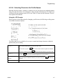
Sending Data to the Panel ............................................................................................ 2-3
2.3
Identifying Serial Numbers and Revision Levels ........................................................ 2-4
2.4
2.3.1
Operating System Revision Level ................................................................... 2-4
2.3.2
Hardware Revision Levels and Serial Numbers .............................................. 2-4
Installation Records ..................................................................................................... 2-4
2.4.1
Serial Number Quick Reference ...................................................................... 2-5
2.4.1.1 Zone Record .......................................................................................... 2-6
150961
i
Model 4821/4820 Control/Communicator Installation Manual
Section 3
Access Control Installation and Operation
3.1
3.2
Model 4421 Installation ............................................................................................... 3-1
3.1.1
Model 4421 Connection to the 4821 ................................................................ 3-3
3.1.2
4205 Touchpad Connection to 4421 ................................................................ 3-4
Card/Proximity Reader Installation ............................................................................. 3-5
3.2.1
Card Reader Specifications .............................................................................. 3-5
3.2.2
Mounting .......................................................................................................... 3-5
3.2.3
Wiring the 4300 Swipe Card Reader ............................................................... 3-7
3.2.4
Wiring the 4330, 4340 and 4350 ProximityReaders ........................................ 3-8
3.3
Wiring the 4860C Touchpad for Door Access ............................................................ 3-9
3.4
Access Control Operation .......................................................................................... 3-10
3.5
3.4.1
Access Control Touchpad Menus .................................................................. 3-10
3.4.2
End-User Operation ....................................................................................... 3-11
3.4.3
Manually Changing Door Schedules ............................................................. 3-12
3.4.4
Viewing Door Status ...................................................................................... 3-12
3.4.5
Anti-Passback Feature ................................................................................... 3-13
3.4.6
Anti-Passback Operations .............................................................................. 3-14
3.4.7
Bulk Loading Access Cards ........................................................................... 3-14
Egress Fail-safe Override Application ....................................................................... 3-15
Section 4
Control Panel Description and Installation
............................ 4-1
4.1
Environmental Specifications ...................................................................................... 4-1
4.2
Electrical Specifications .............................................................................................. 4-1
4.3
Board Layout ............................................................................................................... 4-2
4.4
Terminal Strip Description .......................................................................................... 4-3
4.5
Power Limiting Circuits ............................................................................................... 4-4
4.6
Power Switch ............................................................................................................... 4-5
4.7
Mounting the Model 4821/4820 Panel ........................................................................ 4-5
4.8
Wire Routing ................................................................................................................ 4-6
4.9
Current Draw Worksheets ........................................................................................... 4-7
4.9.1
ii
............................ 3-1
Sample Worksheets ........................................................................................ 4-7
150961
Contents
4.9.2
Worksheet for Silent Knight Modules ............................................................ 4-9
4.9.3
Worksheet for Auxiliary Devices (not Silent Knight) ................................... 4-10
4.9.4
Battery Calculation Worksheet ...................................................................... 4-11
4.9.5
Standby Current For DACT Compliant Installations .................................... 4-11
4.10 AC Power Transformer .............................................................................................. 4-12
4.11 Backup Battery Connection ....................................................................................... 4-13
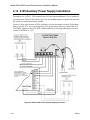
4.12 4195 Auxiliary Power Supply Installation ................................................................. 4-14
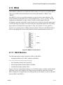
4.13 SBUS ......................................................................................................................... 4-15
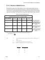
4.13.1 SBUS Modules .............................................................................................. 4-15
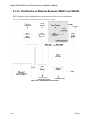
4.13.2 Distribution of Modules Between SBUS1 and SBUS2 ................................. 4-16
4.13.3 Number of SBUS Devices ............................................................................. 4-17
4.14 Touchpad Installation ................................................................................................ 4-18
4.14.1 Touchpad Specifications ................................................................................ 4-18
4.14.2 Mounting Touchpads ..................................................................................... 4-18
4.14.3 Wiring Touchpads .......................................................................................... 4-19
4.15 Zone Installation ........................................................................................................ 4-20
4.15.1 Zone Hardware Specifications ....................................................................... 4-20
4.15.2 Maximum Number of Zones per System ....................................................... 4-20
4.15.3 Zone Configuration ........................................................................................ 4-21
4.15.4 Zone Configuration Examples ....................................................................... 4-22
4.15.5 Wiring a 4860C as an Input Zone .................................................................. 4-24
4.15.6 Zone Response (Debounce) Speed ................................................................ 4-25
4.16 Smoke Detector Wiring and Operation ..................................................................... 4-26
4.16.1 Smoke Detector Compatibility ...................................................................... 4-26
4.16.1.1 Smoke Reset Cycle .............................................................................. 4-26
4.16.1.2 Smoke Verification Cycle ................................................................... 4-26
4.16.2 Four-Wire Smoke Detector Wiring ............................................................... 4-27
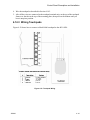
4.17 Speaker Wiring .......................................................................................................... 4-28
4.17.1 Internal Speaker Wiring ................................................................................. 4-28
4.17.2 External Speaker Wiring ................................................................................ 4-28
4.18 Bell Wiring ................................................................................................................ 4-29
4.18.1 Residential Type Bell Wiring ........................................................................ 4-29
4.18.2 Commercial Bell Wiring ................................................................................ 4-30
4.19 4884 Bell Module wiring ........................................................................................... 4-31
150961
iii
Model 4821/4820 Control/Communicator Installation Manual
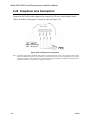
4.20 Telephone Line Connection ....................................................................................... 4-32
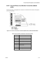
4.20.1 Second Phone Line Monitor Connection (Model 4875) ................................ 4-33
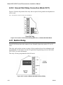
4.20.2 Ground Start Relay Connection (Model 5211) .............................................. 4-34
4.21 Built-in Relay ............................................................................................................. 4-34
4.22 DACT Compliant Wiring .......................................................................................... 4-35
4.22.1 Trouble Output Relay .................................................................................... 4-35
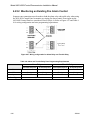
4.22.2 Monitoring an Existing Fire Alarm Control .................................................. 4-36
4.22.3 Monitoring A Sprinkler System ..................................................................... 4-37
Section 5
System Operation
................................................................................................ 5-1
5.1
Partitions and Areas ..................................................................................................... 5-1
5.2
Touchpad Models ........................................................................................................ 5-4
5.3
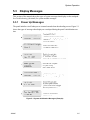
Display Messages ........................................................................................................ 5-5
5.3.1
Power Up Messages ......................................................................................... 5-5
5.3.2
Normal Display Messages ............................................................................... 5-6
5.3.3
System Status Messages .................................................................................. 5-6
5.4
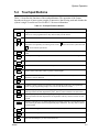
Touchpad Buttons ........................................................................................................ 5-7
5.5
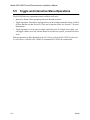
Toggle and Interactive Menu Operations .................................................................... 5-8
5.6
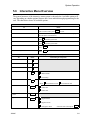
Interactive Menu Overview ......................................................................................... 5-9
5.7
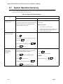
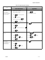
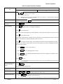
System Operation Summary ...................................................................................... 5-10
5.8
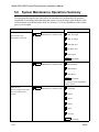
System Maintenance Operations Summary ............................................................... 5-14
5.9
System Test Descriptions ........................................................................................... 5-16
5.9.1
Walk Test ....................................................................................................... 5-16
5.9.2
Dialer Test ...................................................................................................... 5-16
5.9.3
Dialer Reset .................................................................................................... 5-16
5.10 Communicating with the Computer ........................................................................... 5-17
5.10.1 Sending Data To and From the Panel ............................................................ 5-18
5.11 Audible Signals Description and How to Reset ......................................................... 5-19
iv
150961
Contents
Section 6
Programming
............................................................................................................. 6-1
6.1
Downloading ................................................................................................................ 6-1
6.2
Touchpad Programming .............................................................................................. 6-1
6.2.1
General Operation ............................................................................................ 6-1
6.2.2
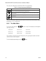
The Main Menu ............................................................................................... 6-2
6.2.2.1 1-Install Device ..................................................................................... 6-3
6.2.2.2 2-Edit System Options ........................................................................... 6-3
6.2.2.3 3-Edit Partition ...................................................................................... 6-4
6.2.2.4 4-Edit Ph. Lines ..................................................................................... 6-4
6.2.2.5 5-Reprt Accounts ................................................................................... 6-5
6.2.2.6 6-Print Accounts .................................................................................... 6-5
6.2.2.7 7-Edit Profiles ........................................................................................ 6-6
6.2.2.8 Selecting Characters for Profile Names ................................................ 6-7
Using the LCD Prompts ...................................................................................... 6-7
Using the Chart (Table 6-3) ................................................................................ 6-8
6.2.2.9 8-Edit Schedules .................................................................................... 6-9
6.2.2.10 9-Delete Options .................................................................................. 6-10
6.3
Activating Safe Mode ....................................................................................... 6-10
Quitting Safe Mode ........................................................................................... 6-10
Programmable Options .............................................................................................. 6-11
6.3.1
System Devices List ....................................................................................... 6-11
6.3.1.1 General System Options Screen .......................................................... 6-11
6.3.1.2 Dialer Screen ....................................................................................... 6-14
6.3.1.3 Devices Screen .................................................................................... 6-15
6.3.2
Partition List and Menus ................................................................................ 6-16
6.3.2.1 Partition Options Screen ...................................................................... 6-16
6.3.2.2 Touchpads / Card Readers Screen ....................................................... 6-20
6.3.2.3 Zones Screen ....................................................................................... 6-23
6.3.2.4 Reporting Accounts Screen ................................................................. 6-27
6.3.2.5 Areas Screen ........................................................................................ 6-30
150961
6.3.3
Time Schedules Screen .................................................................................. 6-31
6.3.4
Time Ranges ..................................................................................................... 6-31
Universal Schedules ....................................................................................... 6-32
6.3.5
User Profiles Screen ....................................................................................... 6-33
6.3.6
Users Screen .................................................................................................. 6-34
v
Model 4821/4820 Control/Communicator Installation Manual
Section 7
Reporting
....................................................................................................................... 7-1
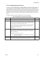
7.1
Compatible UL Listed Receivers ................................................................................. 7-1
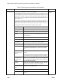
7.2
SIA Event Codes .......................................................................................................... 7-2
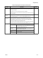
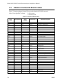
7.3
Ademco Contact ID Event Codes ................................................................................ 7-6
7.4
ASCII Event Descriptions ......................................................................................... 7-10
Section 8
Troubleshooting
vi
.................................................................................................... 8-1
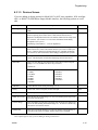
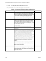
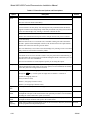
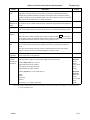
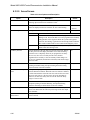
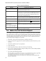
8.1
Error Messages ............................................................................................................ 8-1
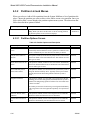
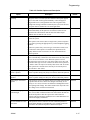
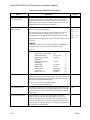
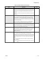
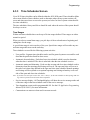
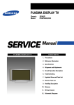
8.2
Before You Call Technical Support ............................................................................. 8-2
150961
Section 1
Introduction
The Model 4821/4820 is a control/communicator for use in residential and commercial
security applications, commercial and residential fire applications. The Model 4821 includes a
sophisticated access control system, through which you can monitor and control user access to
specific areas of a building (see Section 3 for detailed information on access control).
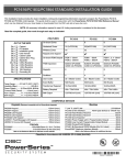
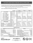
1.1
Overview of System Features
4820
4821
3
3
400 zones, 16 on 4821/4820 board, additional available with expansion devices
(Model 4815 zone expander, Model 4825 zone expander, Model 4860C touchpad)
3
Can use the Model 4421 Door Access Module as an expansion device.
3
8 partitions, 8 areas within each partition
3
32 reporting accounts
3
System Feature
8 reporting accounts
3
3
3
24 touchpads / card readers
3
3
One monitored phone line on 4821/4820 board, expandable to two lines with Model
4875 Second Phone Line Expander
3
100 User Profiles
20 User Profiles
3
3
1800 User Codes
500 Users Codes
3
3
50 Time Schedules (with 20 time ranges each)
25 Time Schedules (with 20 time ranges each)
3
3
3
8 Universal Schedules (with 20 time ranges each)
3
3
2.5 amps power available, expandable to 5.0 amps with 4195 Auxiliary Power
Module
The 4821 and 4820 are shipped with a Model 9227 transformer and 16 Model 7628EOL
resistors (each 4.7 k ohm).
150961
1-1
Model 4821/4820 Control/Communicator Installation Manual
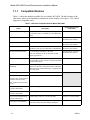
1.1.1
Compatible Modules
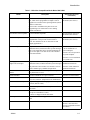
Table 1-1 shows the modules available for use with the 4821/4820. The third column of the
chart shows where to find installation instructions for the module. (See Figure 1-1 for a block
diagram or compatible units.)
Table 1-1: Modules Compatible with the Model 4821/4820
Model
Description
See Section (for more
information)
4195 Auxiliary Power Supply
Provides an additional 2.5 amps of power and allows
for a second 12-volt, 7.0 AH battery to be added to the
system.
Section 4.12 of this manual.
4815 Serial Zone Expander
128-Zone Serial Expander. Used with SmartSensors.
4815 Installation section of
this binder (P/N 150909).
4111 SmartSensors
Serial sensors for use with the 4815.
4815 Installation section of
this binder (P/N 150909).
4114 End-of-Line Resistor
4815 Installation section of
1.43K ohm EOL resistor for use with Model 4111
SmartSensor. The 4114 is required for UL installations. this binder (P/N 150909).
4181X10 Powerline Interface
For connecting X10 modules to the 4880.
(Note: X10 modules are not UL listed for fire and
burglary applications.)
4880 Installation section of
this binder (P/N 150912).
12
For access control installations. Requires the 4421 Door Section 3.1 of this manual
Access Module (see note 1 below). Cannot be used with
the 4820 control panel.
1
4300 Classic Wiegand Swipe
Card Reader
26-bit Wiegand type swipe card reader for indoor or
Section 3.2.3 of this manual
outdoor use. Has fully encapsulated head to withstand
tampering and environmental damage. Compatible with
4301 swipe cards.
13
For use with Model 4300 Card Swipe Reader.
4205 Slimline Touchpad
4301 Wiegand Acces Card
4305 Proxima Clip-on Badge For use with Model 4330/4340/4350 readers.
Proximity Card, 14306 Proxima
Laminated Vinyl Proximity
Card, 14308 Proxima Proximity
Key tag
1
1
4330 Proxima Mullion Mount
Proximity Card Reader
Mullion mount type reader, 26- or 34-bit selectable.
Section 3.2.4 of this manual
4340 Proxima Standard Range Standard range reader, 26- or 34-bit selectable.
Proximity Card Reader
Section 3.2.4 of this manual
4350 Proxima Medium Range
Proximity Card Reader
Medium range reader, 26- or 34-bit selectable.
Section 3.2.4 of this manual
13
Hardware interface for 26-bit or 34-bit Wiegand type
card readers and for the 4205 Slimline Touchpad.
Section 3.1 of this manual
1
1
4421 Door Access Module
1-2
150961
Introduction
Table 1-1: Modules Compatible with the Model 4821/4820
Model
4824 Serial/Printer Interface
Description
See Section (for more
information)
Provides one RS-232 serial port and one parallel printer 4824 Installation section of
port, which can be programmed to output events in
this binder (P/N 150911).
English text or in either of the reporting formats (SIA or
Ademco Contact ID).
Can be used to send data to the panel for on-site
programming or for connection to a PC running
4850ACAS software.
4825 Hardwire Zone Expander
64-Zone Hardwire Expander.
4825 Installation section of
this binder (P/N 150910).
4880 Status Output Module
Provides 16 outputs and 4 relays that are fully
programmable. Also provides an X10 interface.
4880 Installation section of
this binder (P/N 150912).
(Note: X10 modules are not UL listed for fire and
burglary applications.)
4860C Touchpad
Fully featured commercial touchpad using an LCD to
annunciate alarms, troubles and other system messages.
Has 2 zone inputs that can be used for hardwiring any
type of zone input, or for door access. Has a built-in
card reader interface.
In this manual, refer to Section
4.14 for installation as a
system touchpad.
Section 3 and 5 for operation
of system touchpad.
Section 4.15.5 for installation
as a system zone.
4860R (gray) and 4860Rx
(bright white) Touchpad
Fully featured residential touchpad using an LCD to
Section 4.14 of this manual for
annunciate alarms, troubles and other system messages. installation instructions.
Only difference between these two models is color of
plastic. 4860R is gray; 4860Rx is bright white.
Section 4 of this manual for
operation instructions.
4875 Second Phone Line
Monitor
Provides termination for second phone line. Required if Section 4.20.1 of this manual.
two phone lines are used.
4884 Bell Module
Provides termination for a supervised bell
Section 4.19 of this manual.
4890 Accessory Enclosure
Secured cabinet to mount additional modules such as
4815, 4421, 4880 etc. (Required for UL installations.)
Section 1.1.2 of this manual.
5211 Ground Start Relay
Required for applications using a ground start telephone Section 4.20.2 of this manual.
network. (Not UL listed.)
6712 Battery
12 VDC 7 amp hour Gell Cell battery for use with the
4821/4820.
Section 4.11 of this manual.
7628 End-of-Line Resistor
4.7 k ohms EOL resistor used for all input zones
(except 4815 SmartSensor zones).
16 EOLs are shipped with the 4821/4820.
Section 4.15 of this manual.
7860 Telephone Cord
RJ31X cord for connecting phone line to the 4821/
4820.
Section 4.20 of this manual.
9000 Receiver
For use with the SIA-20 format.
Section 7 of this manual.
(Section 7 also lists other
receivers compatible with the
4821/4820.)
150961
1-3
Model 4821/4820 Control/Communicator Installation Manual
1. Not UL listed with 4820 control panel.
2. Not UL listed for access control.
3. Can not be used with the 4820 control panel.
Figure 1-1 Model 4821/4820 and Compatible Modules
1-4
150961
Introduction
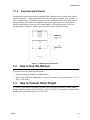
1.1.2
Accessory Enclosure
In applications where more than two additional 4815 modules are to be used in the control
panel “snap tracks”, a model 4890 alarm accessory enclosure is required. (See Section 1.4.3
for UL requirements.) The Model 4890 has the same dimensions as the 4821/4820 control
panel enclosure and contains two additional snap tracks. One snap track is designed for
smaller width boards such as the 4815 control module. The other snap track is sized to
accommodate the larger PC boards such as the 4824, 4880, and 4421 modules.
Figure 1-1 4890 Accessory Enclosure
1.2
How to Use this Manual
The manual uses the following conventions:
•
A clear rectangle represents a touchpad button.
•
Pages of the manual are numbered by section. For example, a page numbered as “5-1” is
Page 1 of Section 5.
1.3
How to Contact Silent Knight
If you have a question or encounter a problem not covered in this manual, contact: Silent
Knight Technical Support at 800-328-0103 (or 612-493-6455). To order parts, contact Silent
Knight Sales at 800-446-6444 (or 612-493-6435).
150961
1-5
Model 4821/4820 Control/Communicator Installation Manual
1.4
1.4.1
Agency Requirements
Telephone Requirements
If requested by the telephone company, the following information must be provided before
connecting this device to the phone lines:
A.
Manufacturer:
Silent Knight Security Systems
B.
Model Number:
4821/4820
C.
FCC Registration Number:
AC6USA-22755-AL-E
D.
Type of jack (to be installed by the
telephone company):
RJ31X
Ringer equivalence:
0.9B
This device may not be connected directly to coin telephones or party line services.
This device cannot be adjusted or repaired in the field. In case of trouble with the device,
notify the installing company or return the device to the manufacturer:
Silent Knight Security Systems
7550 Meridian Circle
Maple Grove, MN 55369-4927
800-328-0103 or 612-493-6455
The telephone company may make changes in its facilities, equipment, or procedures that
could affect the operation of the equipment. If this happens, the telephone company will
provide advance notice to allow you to make the necessary modifications to maintain
uninterrupted service.
1.4.2
FCC Warning
This device has been verified to comply with FCC Rules Part 15. Operation is subject to the
two following conditions: (1) This device may not cause radio interference, and (2) This
device must accept any interference received including interference that may cause undesired
operation.
1-6
150961
Introduction
1.4.3
UL Requirements
If installed in accordance with these requirements, the Model 4821/4820 is UL listed for
Grade A Mercantile, Local Police Station Connect with Basic Line Security, and Grade B and
C Central Station Service.
Follow the requirements below if you are installing a UL listed application. See Section
1.4.3.1 for Household Fire and Burglary Warning System installation requirements. See
Section 1.4.3.2 for Grade A Mercantile installation requirements.
1. The Model 4860C (commercial) or 4860R (residential) touchpad must be used. Each
SBUS must have at least one touchpad connected (minimum of two touchpads per installation).
2. Entry delays must not be longer than 45 seconds. An exit delay must not be longer than 60
seconds.
3. All panic zones (including touchpad panic zones) must be programmed as silent and invisible.
Note: Silent and invisible reports can be seen by pressing status or reviewing the event history.
4. The Audible Trouble Alert When Armed option (programmed in Area Menu) must be
selected.
5. Do NOT select the following optional features:
Automatic closing or opening (programmed in the Area Menu)
Swinger Bypass Timeout (programmed in Area Menu)
6. Partitions are allowed in UL burglary installations only if the protected premises falls
under one ownership and the operation of a single authority. An example of an acceptable
installation is a common building operated by one company which may need to subdivide
the system to allow independent entry and exit. A strip mall is an example of an application that would not be allowed in a UL installation. Partitioning cannot be used for fire
zones. (See Item 9. below for additional information about partitioning.)
7. If the cross-alarm feature is used, it must be used only by detectors that share a common
field of view.
8. A complete functional checkout of the system must be performed any time the system is
programmed or reprogrammed. (Zone bypassing or other temporary changes necessary for
troubleshooting are an exception to this requirement.)
9. Bells must be the primary source of alarm annunciation. Speakers can be used as an additional source. Grade C Central Station installations are an exception; bells are not required
in these installations. In a multi-partition system, bells must be protected by a
24-hour circuit.
10. Opening and closing signals must be enabled in a Central Station installation.
150961
1-7
Model 4821/4820 Control/Communicator Installation Manual
11. In applications requiring more than two modules 4815 to be located in the control panel
snap track, a model 4890 alarm accessory enclosure is required. (See Section 1.1.2.)
12. Do not eliminate the default I/O programming script. Doing so could cause the bell sounds
to be deleted from the system.
Note: The script can be modified to include additional functions, but the default statements must remain intact.
1.4.3.1 Household Burglary Warning System
If you are installing the 4821/4820 in a UL listed residential installation, follow the
requirement below in addition to those listed in Section 1.4.3.
The Audio Shutdown Delay option must be programmed as 4 minutes.
1.4.3.2 Grade A Mercantile
For a Grade A Mercantile listing, follow the requirements below in addition to those listed in
Section 1.4.3.
1. You must program a time schedule for auto testing to occur (programmed in Time
Schedules Menu).
2. The Audio Shutdown Delay option must be programmed to 15 minutes.
3. A listed tamper switch must protect the inside front door of the enclosure. This switch
must be connected to an intrusion input zone of the control unit which is programmed as a
perimeter zone.
4. All unused knockout holes on the cabinet must be plugged using bolts and washers.
(Model 7600 is a kit available from Silent Knight for this purpose.) See Section 4.7 for
installation instructions.
5. Four pan head screws #8x3”, type AB (thread forming tapping screws) must be placed in
the 4821/4820 cabinet cover to increase the panel’s attack resistance.
6. A separately listed Ademco AB-12 Bell in Box must be used with the control unit.
7. The tamper switches of the alarm bell must be connected to a 24-hour zone. No other initiating devices may be connected to this loop. The outer housing of the bell box must be
grounded. The bell circuit should be installed in accordance with UL requirements.
8. All bell wiring must be run in its own conduit and must be connected to the control unit
using its own knockout hole.
1-8
150961
Introduction
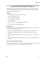
1.4.3.3 Commercial & Residential Fire Digital Alarm Communicator
Transmitter (DACT) UL 864, NFPA 72 (Chapter 4)
The DACT listing allows the 4821/4820 to be used to monitor an existing local fire alarm
control and/or a sprinkler system. For the 4821/4820 to be used as a DACT, the following
requirements must be complied with:
Hardware:
• A minimum of one 4860C Commercial Touchpad.
•
Two 4165 Transformer Covers.
•
A 4195 Auxiliary Power Supply.
•
A 4875 Dual Phone Line Module.
•
A 4884 Bell Module.
•
Two 6712 12 VDC 7AH Standby Battery or Equivalent.
•
Power switch bypass jumpers must not be cut.
Programming:
The following options must be selected when programming the control panel. (See Section 6
Programming for programming information.):
1. In the Low AC Report Time (Section 6.3.1.1) must be set between 6 and 12 hours.
2. In the Phone Line Enabled (Section 6.3.1.2) 2 Phone Lines option must be must be
selected.
3. In the Ground Start Telephone Network Used option (Section 6.3.1.2) must remain disabled.
4. In the Phone Line Monitor Enabled option (Section 6.3.1.2) the Line Monitor option must
be selected.
1.4.3.4 Access Control UL-294
All 4860C touchpads must be located within the protected premises. The 4820 is not listed for
access control.(See Section 3 for access control installation information.)
150961
1-9
Model 4821/4820 Control/Communicator Installation Manual
1-10
150961
Section 2
Quick Start
This section is intended to help you determine if any problems exist with the system you are
about to install. Perform the steps below in the order shown here.
1. Wire a touchpad to one of the four-wire serial buses (SBUS). See Section 4.14 for more
information. (See Note below.)
2. Plug in the transformer and apply AC.
3. Hook up the battery.
4. The touchpad will initialize. Several messages, including the touchpad serial number, will
display for approximately one second. When the message “482x Engaged” (x indicates
that the display would read 1 for a 4821, or 0 for a 4820) is displayed, it means the system
has booted up successfully. The default date and time is displayed.
5. Set system date and time. You may use the default code to test the system. See the instructions on the next page for more information.
If you are able to set the date and time successfully, it means the system is up and running.
6. From here you can send your programmable options to the panel, if you have programmed
them through the Model 5580 Upload-Download Software. (See Section 2.2.)
Note: To attach a temporary touchpad to the system, you do not need to know its serial number. To permanently
attach any SBUS device, including a touchpad, you must enter its serial number into the system.
150962
2-1
Model 4821/4820 Control/Communicator Installation Manual
2.1
Setting System Time and Date
To set the time:
1. Press
1
ENTER
[Code]. (Installer Code is factory-programmed as 1234.)
2. At the menu prompt, enter
1
to select “Time”.
3. Enter digit(s) for hour in 24-hour military format, then press
4. Enter digit(s) for minute, then
ENTER
ENTER
.
.
Note that if the “Auto DST Adjustment” feature has been enabled, a message will display
when you set the time.
Example:
To change the system time to 3:45 p.m., the keystrokes are:
1
ENTER
1
5
ENTER
4
5
ENTER
[Code]
1
To set the date:
1.
1
ENTER
[Code]
2. At the menu prompt, enter
2
to select “Date”.
3. Enter digit(s) for month, then press
4. Enter digit(s) for date, then press
ENTER
ENTER
5. Enter four digits for year, then press
.
.
ENTER
.
Example:
To change the system date to July 15, 1996, the keystrokes are:
2-2
1
ENTER
7
ENTER
1
5
ENTER
1
9
9
[Code]
6
2
ENTER
150962
Quick Start
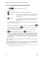
2.2
Sending Data to the Panel
See Section 5.10 of this manual for complete information about communication.
1. Press
4
ENTER
[Installer or Maintenance Code]
2. At the menu, select:
1
for Internal Phone. This option is for downloading via the phone lines.
2
for 4824 Modem. With this type of communication, a Hayes compatible modem is connected to both the 4824 and the PC, allowing for faster data transmission.
3
for 4824 Direct. This option is for directly connecting the 4824 to the computer using a
null modem cable (both the computer and the 4821/4820 are on-site).
3. If you select either 4824 option (2 or 3), you will be prompted to select the 4824 from the
list of 4824s installed in the system.
4. If the phone number that displays is not correct, enter the correct digits and press
ENTER
. (If
ENTER
the phone number is correct, press
to bypass this step.) If you have selected the 4824
Direct option, this step will not appear.
5. If the Account number that displays is not correct, enter the correct digits and press
(If the account number is correct, press
ENTER
ENTER
.
to bypass this step.)
6. The system will attempt to communicate. If the communication attempt was successful,
the panel will re-initialize. Do not power the system down during the re-initialization
period.
Note: If the 5580 has no task in its queue, the panel will always send an upload. The 5580 must have a download
in its queue for this account in order for the download to occur.
150962
2-3
Model 4821/4820 Control/Communicator Installation Manual
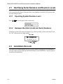
2.3
Identifying Serial Numbers and Revision Levels
This section describes how to determine the levels of hardware and 4821/4820 software that
are used with your panel.
2.3.1
Press
4
Operating System Revision Level
STAT
to see a display of the revision date.
16:51:03
O ct 19 1995
2.3.2
Hardware Revision Levels and Serial Numbers
Hardware revision levels and serial numbers are printed on labels on the circuit board. Look
for “S/N” followed by an 8-digit number.
2Qb S_TY^W
S /N 00000603 4821 H .1
BUf CUbYQ\ =_TU\ 2.4
Installation Records
You can use the following pages to keep a record of options programmed for an installation.
You may want to use the charts for up-front planning of your installations. Copy the pages as
needed for all installations.
2-4
150962
Quick Start
2.4.1
Serial Number Quick Reference
Use the chart below to keep track of hardware device serial numbers.
Customer Name __________________________________
Location ________________________________________
Account Number _________________________________
Installation Code _________________________________
Device #
Description
4421 Door Access Module /
4860 Touchpads
1
2
Serial #
Device #
Description
Serial #
4880 Status Output Module
1
2
3
3
4824 Serial/Parallel Module
4
5
6
7
8
9
10
11
12
1
2
3
4
5
6
7
8
4825Hardwire Zone Expander
13
14
15
16
17
18
19
1
2
3
4
5
6
4815Serial Zone Expander
20
21
22
1
2
23
24
150962
3
2-5
Model 4821/4820 Control/Communicator Installation Manual
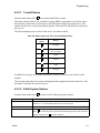
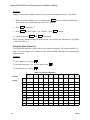
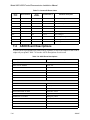
2.4.1.1 Zone Record
Use the charts in this section to record zone identification information.
Table 2-1: Internal Zones
Zone #
2-6
Hardware
Point
Location
Partition #
Areas
1
1 2 3 4 5 6 7 8
2
1 2 3 4 5 6 7 8
3
1 2 3 4 5 6 7 8
4
1 2 3 4 5 6 7 8
5
1 2 3 4 5 6 7 8
6
1 2 3 4 5 6 7 8
7
1 2 3 4 5 6 7 8
8
1 2 3 4 5 6 7 8
9
1 2 3 4 5 6 7 8
10
1 2 3 4 5 6 7 8
11
1 2 3 4 5 6 7 8
12
1 2 3 4 5 6 7 8
13
1 2 3 4 5 6 7 8
14
1 2 3 4 5 6 7 8
15
1 2 3 4 5 6 7 8
16
1 2 3 4 5 6 7 8
150962
4825 Hardwire Zone Expander ______Serial Number ____________Device Number _____
Zone
H/W Pt
Location
Partition
Areas
Zone
H/W Pt
Location
Partition
Areas
1
12345678
33
12345678
2
12345678
34
12345678
3
12345678
35
12345678
4
12345678
36
12345678
5
12345678
37
12345678
6
12345678
38
12345678
7
12345678
39
12345678
8
12345678
40
12345678
9
12345678
41
12345678
10
12345678
42
12345678
11
12345678
43
12345678
12
12345678
44
12345678
13
12345678
45
12345678
14
12345678
46
12345678
15
12345678
47
12345678
16
12345678
48
12345678
17
12345678
49
12345678
18
12345678
50
12345678
19
12345678
51
12345678
20
12345678
52
12345678
21
12345678
53
12345678
22
12345678
54
12345678
23
12345678
55
12345678
24
12345678
56
12345678
25
12345678
57
12345678
26
12345678
58
12345678
27
12345678
59
12345678
28
12345678
60
12345678
29
12345678
61
12345678
30
12345678
62
12345678
31
12345678
63
12345678
32
12345678
64
12345678
4815 Expander
Zone
H/W Pt
Loop1 Addresses Serial Number ________Device Number ____
Location
Partition
Areas
Zone
H/W Pt
Location
Partition
Areas
Loop1, Addr 1
12345678
Loop1, Addr 33
12345678
Loop1, Addr 2
12345678
Loop1, Addr 34
12345678
Loop1, Addr 3
12345678
Loop1, Addr 35
12345678
Loop1, Addr 4
12345678
Loop1, Addr 36
12345678
Loop1, Addr 5
12345678
Loop1, Addr 37
12345678
Loop1, Addr 6
12345678
Loop1, Addr 38
12345678
Loop1, Addr 7
12345678
Loop1, Addr 39
12345678
Loop1, Addr 8
12345678
Loop1, Addr 40
12345678
Loop1, Addr 9
12345678
Loop1, Addr 41
12345678
Loop1, Addr 10
12345678
Loop1, Addr 42
12345678
Loop1, Addr 11
12345678
Loop1, Addr 43
12345678
Loop1, Addr 12
12345678
Loop1, Addr 44
12345678
Loop1, Addr 13
12345678
Loop1, Addr 45
12345678
Loop1, Addr 14
12345678
Loop1, Addr 46
12345678
Loop1, Addr 15
12345678
Loop1, Addr 47
12345678
Loop1, Addr 16
12345678
Loop1, Addr 48
12345678
Loop1, Addr 17
12345678
Loop1, Addr 49
12345678
Loop1, Addr 18
12345678
Loop1, Addr 50
12345678
Loop1, Addr 19
12345678
Loop1, Addr 51
12345678
Loop1, Addr 20
12345678
Loop1, Addr 52
12345678
Loop1, Addr 21
12345678
Loop1, Addr 53
12345678
Loop1, Addr 22
12345678
Loop1, Addr 54
12345678
Loop1, Addr 23
12345678
Loop1, Addr 55
12345678
Loop1, Addr 24
12345678
Loop1, Addr 56
12345678
Loop1, Addr 25
12345678
Loop1, Addr 57
12345678
Loop1, Addr 26
12345678
Loop1, Addr 58
12345678
Loop1, Addr 27
12345678
Loop1, Addr 59
12345678
Loop1, Addr 28
12345678
Loop1, Addr 60
12345678
Loop1, Addr 29
12345678
Loop1, Addr 61
12345678
Loop1, Addr 30
12345678
Loop1, Addr 62
12345678
Loop1, Addr 31
12345678
Loop1, Addr 63
12345678
Loop1, Addr 32
12345678
Loop1, Addr 64
12345678
4815 Expander
Zone
H/W Pt
Loop2
Location
Partition
Areas
Zone
H/W Pt
Location
Partition
Areas
Loop2, Addr 1
12345678
Loop2, Addr 33
12345678
Loop2, Addr 2
12345678
Loop2, Addr 34
12345678
Loop2, Addr 3
12345678
Loop2, Addr 35
12345678
Loop2, Addr 4
12345678
Loop2, Addr 36
12345678
Loop2, Addr 5
12345678
Loop2, Addr 37
12345678
Loop2, Addr 6
12345678
Loop2, Addr 38
12345678
Loop2, Addr 7
12345678
Loop2, Addr 39
12345678
Loop2, Addr 8
12345678
Loop2, Addr 40
12345678
Loop2, Addr 9
12345678
Loop2, Addr 41
12345678
Loop2, Addr 10
12345678
Loop2, Addr 42
12345678
Loop2, Addr 11
12345678
Loop2, Addr 43
12345678
Loop2, Addr 12
12345678
Loop2, Addr 44
12345678
Loop2, Addr 13
12345678
Loop2, Addr 45
12345678
Loop2, Addr 14
12345678
Loop2, Addr 46
12345678
Loop2, Addr 15
12345678
Loop2, Addr 47
12345678
Loop2, Addr 16
12345678
Loop2, Addr 48
12345678
Loop2, Addr 17
12345678
Loop2, Addr 49
12345678
Loop2, Addr 18
12345678
Loop2, Addr 50
12345678
Loop2, Addr 19
12345678
Loop2, Addr 51
12345678
Loop2, Addr 20
12345678
Loop2, Addr 52
12345678
Loop2, Addr 21
12345678
Loop2, Addr 53
12345678
Loop2, Addr 22
12345678
Loop2, Addr 54
12345678
Loop2, Addr 23
12345678
Loop2, Addr 55
12345678
Loop2, Addr 24
12345678
Loop2, Addr 56
12345678
Loop2, Addr 25
12345678
Loop2, Addr 57
12345678
Loop2, Addr 26
12345678
Loop2, Addr 58
12345678
Loop2, Addr 27
12345678
Loop2, Addr 59
12345678
Loop2, Addr 28
12345678
Loop2, Addr 60
12345678
Loop2, Addr 29
12345678
Loop2, Addr 61
12345678
Loop2, Addr 30
12345678
Loop2, Addr 62
12345678
Loop2, Addr 31
12345678
Loop2, Addr 63
12345678
Loop2, Addr 32
12345678
Loop2, Addr 64
12345678
Model 4821 Control/Communicator Installation Manual
2-10
150962
Section 3
Access Control Installation and Operation
This section of the manual describes the installation of access control hardware manufactured
by Silent Knight and applies to the 4821 control panel only. Section 4 of this manual describes
installation of other required or optional hardware devices.
IMPORTANT!
All circuits are power limited, Class II.
3.1
Model 4421 Installation
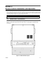
Figure 3-1 shows the layout of the 4421 board. Table 3-1 (next page) is a terminal strip
description.
Figure 3-1 Model 4421 Board Layout
150963
3-1
Model 4821/4820 Control/Communicator Installation Manual
Table 3-1: Model 4421 Terminal Description
Name
3-2
Wire
Color
Terminal Description
Electrical Rating
1 S-
Expansion Bus (-)
0 VDC (circuit ground)
2 S+
Expansion Bus (+)
12 VDC, 1 Amp max.
3A
Expansion Bus (data)
5 VDC
4B
Expansion Bus (data)
5 VDC
5 +PZT
PZT power output
4 VDC, 10 mA
8.3 VDC, 10 mA
6 LED PWR
Brown
4205 LED output
7 COL1
Red
4205 column 1 output
8 COL0
Orange
4205 column 0 output
9 KEY2
Yellow
4205 row 4 input
10 KEY1
Green
4205 row 1 input
11 KEY0
Blue
4205 row 0 input
12 GROUND
Black &
Shield
Circuit Ground
13
+READER
Red
Card reader power output
14 DATA 1s
White
Card reader data 1’s input
15 DATA 0s
Green
Card reader data 0’s input
16 CR LED
Brown
Card reader LED output
3.75 VDC, 25 mA
17 N.O. 1
Relay Contact (Normally Open) #1
2.5 Amps max. @ 24 VDC
18 COMN 1
Relay Contact (Common) #1
19 N.C. 1
Relay Contact (Normally Closed) #1
20 1
Zone Input 1
14 VDC, 1.5 mA
21 C+
Zone power
12 VDC, 3.0 mA
22 2
Zone Input 2
14 VDC, 1.5 mA
23 N.O. 2
Relay Contact (Normally Open) #2
2.5 Amps max. @ 24 VDC
24 COMN 2
Relay Contact (Common) #2
5 VDC, 75 mA
150963
Access Control Installation and Operation
3.1.1
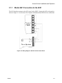
Model 4421 Connection to the 4821
The 4421 Interface connects to the 4821 panel via the SBUS. Connect the 4421 to the panel as
shown in Figure 3-2. See Section 4 for complete information about SBUS device connections.
Figure 3-2 Wiring Diagram 4421of N to the Control Panel
150963
3-3
Model 4821/4820 Control/Communicator Installation Manual
3.1.2
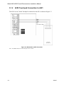
4205 Touchpad Connection to 4421
The 4205 Access Control Touchpad is connected to the 4421 as shown in Figure 3-3.
Figure 3-3 Model 4421 to 4205 Connection
Note: The Model 4205 is not UL listed for access control.
3-4
150963
Access Control Installation and Operation
3.2
Card/Proximity Reader Installation
The Model 4421 Access Control Interface is compatible with 26-bit (plus a leading and trailing parity bits), 24-bit (plus a start-bit and a trailing parity bit), 32-bit, 34-bit (32 data plus a
start-bit and a trailing parity bit), and 34-bit (32 data plus a leading and trailing parity bit)
Wiegand-format readers. (See Figure Figure 3-4.) The following sections describe how to
install the 4300 series readers. Refer to device manual for other manufacturers’ products.
32 Bit
26 or 34 Bit
Figure 3-4 Block Diagram of Wiegand Formats
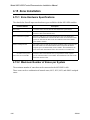
3.2.1
Card Reader Specifications
The 4300 Swipe Card Reader, and the 4330, 4340, and 4350 Proximity Readers require
shielded cable. The chart below shows the specifications.
Supply
Voltage
Model
Max.
Supply
Current
Output
Sink
Output
Source
Current
Output
Pulse
Width
Operating
Temp.
Max. Reader to Receiver
Distance
Gauge
Distance
4300
5 VDC
(+ or -5%)
25 mA
48 mA
5 mA
20 µs typ.
-40 ° to 130° F
24 AWG
18 AWG
85 m (270’)
137 m (450’)
4330
12 VDC
(+ or -5%)
80 mA
48 mA
5 mA
20 µs typ.
-22 ° to 149° F
24 AWG
18 AWG
85 m (270’)
137 m (450’)
4340
12 VDC
(+ or -5%)
80 mA
48 mA
5 mA
20µs typ.
-22 ° to 149° F
24 AWG
18 AWG
85 m (270’)
137 m (450’)
4350
12 VDC
(+ or -5%)
150 mA
48 mA
5 mA
20µs typ.
-22 ° to 149° F
24 AWG
18 AWG
85 m (270’)
137 m (450’)
3.2.2
Mounting
Mount the 4300 series readers on any flat vertical surface.
Use two #10 bolts to mount the reader. Once the reader is mounted, cover the reader front by
applying the pressure-sensitive dress panel or label.
When mounting the proximity readers, use flat-head screws. Drill a one-quarter inch (0.6 cm)
or larger hole for the cable. Refer to the mounting template included with the reader for location of screw holes.
150963
3-5
Model 4821/4820 Control/Communicator Installation Manual
If the card readers will be in a location where they will be exposed to snow, mount in a vertical position to prevent accumulated snow from clogging the card slot.
3-6
150963
Access Control Installation and Operation
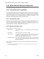
3.2.3
Wiring the 4300 Swipe Card Reader
Wire the swipe card reader to the 4421 Door Access Module as shown in Figure 3-5. The card
reader LED is on when the door relay is activated. The LED is off when the relay is deactivated or when there is no power. (The 4421 LED has the same meaning.)
Figure 3-5 Model 4421 to 4300 Connection
150963
3-7
Model 4821/4820 Control/Communicator Installation Manual
3.2.4
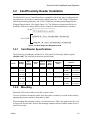
Wiring the 4330, 4340 and 4350 ProximityReaders
Wire the Proximity Reader to the 4421 Door Access Module as shown in Figure 3-6. The card
reader LED is on when the door relay is activated. The LED is off when the relay is deactivated or there is no power. (The 4421 LED has the same meaning.)
Figure 3-6 Model 4330, 4340 and 4350 Connection
3-8
150963
Access Control Installation and Operation
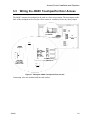
3.3
Wiring the 4860C Touchpad for Door Access
The 4860C commercial touchpad can be used as a door access station. The zone inputs on the
back of the touchpad can be wired to a door contact or could be used for any other purpose.
*Use Cable Assembly
P/N 130375
*Use Cable Assembly
P/N 130378N-750-
Figure 3-7 Wiring the 4860C Touchpad for Door Access
Connecting wires are included with the card readers.
150963
3-9
Model 4821/4820 Control/Communicator Installation Manual
Table 3-2: Connector Descriptions
P2 (Card Reader)
Pin
Number
Description
P4 (Door Access)
(P/N 130375)
Wire Color
Pin
Number
Description
(P/N 130378)
Wire Color
1
Circuit Ground
Black
1
C+ is +12V
Brown
2
LED
Brown
2
Zone Input 1
Red
3
Data 0’s
Green
3
Relay Contact
(Common)
Orange
4
Data 1’s
White
4
Relay Contact
(Normally Open)
Yellow
5
+5 VDC
Red
5
Relay Contact
(Normally Closed)
Green
6
Not used
Blue
7
Zone Input 2
Violet
8
C+ is +12V
Gray
3.4
Access Control Operation
This section of the manual describes operation of access control features. An overview of
these operations is included in the Operations Summary in Section 5 of this manual.
3.4.1
Access Control Touchpad Menus
The
DOOR
BYPS
and
DOOR
ENTR
The
DOOR
BYPS
menu is for controlling door lock/unlock schedules from the touchpad (see
menus are for maintenance level access control operations.
Section 3.4.3 for more information). The DOOR ENTR menu is for controlling users’ antipassback status (see Section 3.4.6). A brief summary of end-user operations are in section
3.4.2.
3-10
150963
Access Control Installation and Operation
3.4.2
End-User Operation
Normal end-user door access operation (accessing a door, opening an outside door from
within, and so on) are described in the Census 4821 Owner’s Manual (P/N 150952). They are
summarized below:
Opening an access controlled door
Present your card to the card reader. You will hear a click and the red
LED will turn green indicating that the door can be opened.
OR
Press
Opening an access controlled door for
another person (granting access)
DOOR
plus your PIN.
This operation would apply at a door station where a receptionist,
security guard, or other person “buzzes in” another person after
identification.
DOOR
and your
Enter the device ID number of the door, then press
PIN. You may hear a click or buzzing sound indicating that the door
can be opened.
Opening a high security door
High security doors are used to secure areas within an installation
that not all employees are allowed to access. Both a card and a PIN
are required to gain access.
Present your card. The touchpad will display ENTER CODE. Enter
your PIN.
150963
3-11
Model 4821/4820 Control/Communicator Installation Manual
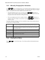
3.4.3
Manually Changing Door Schedules
The DOOR BYPS menu is for changing door access schedules from the touchpad. You can use
this feature to temporarily override door schedules. Any operations made using the touchpad
will be overridden the next time the schedule for the door takes effect.
•
From the touchpad assigned to the current door, press, DOOR BYPS [Maintenance or
Installer’s Code]. The status of the door will display for a few seconds then a menu with
the options shown in the chart below will begin scrolling.
•
From any touchpad, enter the device number of the door,
Installer’s Code]. For example, to access Door #4, press
Installer’s Code].
4
DOOR
DOOR
BYPS
[Maintenance or
BYPS
[Maintenance or
The status of the door will display for a few seconds then a menu with the options shown in
the chart below will begin scrolling.
0 - Unlock Door
Unlocks the door until the next scheduled lock time. Use this option to unlock a door
that is currently scheduled to be locked. All users will be able to access the door.
9 - Lock Door
Locks the door until the next scheduled unlock time. Use this option to lock a door
that is currently scheduled to be unlocked. No users will be able to access the door
without a card or a code.
1 - To Sched
Restores the selected door to its scheduled setting.
2 - All Sched
Restore all doors to their scheduled settings.
3 - All Locked
Lock all doors. Overrides all door schedules.
4 - Select Door
Select another door to lock or unlock.
5 - Access Door
Open a door to allow individual access (not the same as unlocking).
STAT - STATUS
View the status of the door.
3.4.4
Press DOOR
displays.
3-12
Viewing Door Status
STAT
to view the door status. A list of doors and their locked/unlocked status
150963
Access Control Installation and Operation
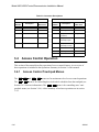
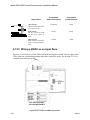
3.4.5
Anti-Passback Feature
The anti-passback feature prevents users from giving access to others by “passing back” their
access cards. In a typical anti-passback installation, users must “register” themselves by
accessing a door programmed as Entry when they enter the building. They will only be
allowed to leave from a door programmed as Exit. A user cannot access an Entry door twice
consecutively. The DOOR ENTR menu allows users to be “forgiven” (allowed access even if
they have not exited properly) and provides other anti-passback options. See Section 3.4.6.
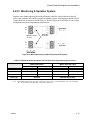
Figure 3-8 below shows an example of anti-passback application. In this example, employees
enter through an anti-passback doors (must enter and exit through separate doors). The manager’s entrance is not an anti-passback door, allowing employees to come and go freely.
Note: The anti-passback feature must be enabled through programming. See Section 6.
Figure 3-8 Sample Anti-Passback Application
150963
3-13
Model 4821/4820 Control/Communicator Installation Manual
3.4.6
Anti-Passback Operations
The DOOR ENTR menu is for controlling the anti-passback feature. It allows you to change
users’ anti-passback status so that they can access or be prevented from accessing the system.
When you press
display.
DOOR
ENTR
[Maintenance or Installer’s Code], the following menu options
1 - User Status
Use to check the user’s current status (for example, In or Out).
2 - Forgive
Forgive means allow the user to enter or exit a door even though the system has
detected a problem with the users’ anti-passback status.
3 - Lockout User
Change the user’s status so he or she will be unable to enter the building.
4 - Num User In
Use this option to see how many users have “In” status.
5 - Forgive All
Reset anti-passback status and allow all users to enter the next time they attempt.
MUTE - Exit
Press to exit the menu.
3.4.7
Bulk Loading Access Cards
Bulk loading of access card allows you to enter multiple successive access cards in one procedure. Follow these steps to bulk load access cards:
1. This can be done by pressing
7
ENTR
.
The display on the touchpad will read:
(OUFS 6FMFDUJPO
&IBOHF VTFST (then)
2. Press
2
(OUFS 6FMFDUJPO
%VML MPBE
then enter the user ID you wish to start with followed by
ENTR
.
The display on the touchpad will read:
3SPGJMF 3. When prompted, enter a profile number followed by the
ENTR
key.
The display on the touchpad will read:
&BSE GPS ,E ;;;;
Note: XXXX equals the number entered in step 2.
4. Present a valid access card to the card reader.
The access card will be added to the system immediately followed by a success beep. The
user ID will increase by one.
Note: If the card is already in the system, a failure beep sounds and you are taken back to step 2.
5. Repeat step 4 until all access cards are presented.
3-14
150963
Access Control Installation and Operation
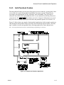
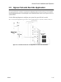
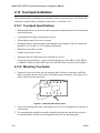
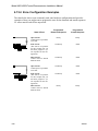
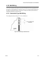
3.5
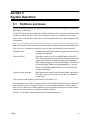
Egress Fail-safe Override Application
An egress fail-safe override is an optional configuration that can be used to give the installation an additional means of exit through access controlled doors in the case of power loss or a
system failure.
Use the following diagrams to configure your system for egress fail-safe override.
Note: In each of the diagrams the egress device can be a motion detector, a crash bar, a button, a beam, etc.
Figure 3-9 Fail-safe Override N.C. Configuration to a Door Access Module
150963
3-15
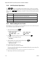
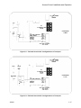
Model 4821/4820 Control/Communicator Installation Manual
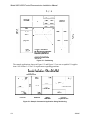
Note: Input 1 must be programmed for “Not ready” on short.
Figure 3-10 Fail-safe Override N.O. Configuration to a Door Access Module
3-16
150963
Access Control Installation and Operation
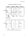
Figure 3-11 Fail-safe Override N.C. Configuration to a Touchpad
Figure 3-12 Fail-safe Override N.O. Configuration to a Touchpad
150963
3-17
Model 4821/4820 Control/Communicator Installation Manual
3-18
150963
Section 4
Control Panel Description and Installation
Warning:
To avoid the risk of electrical shock, do not apply power to the Model 4821/4820 until
you have read these instructions carefully.
This section describes how to install the control panel and some accessories, including compatible add-on modules, such as smoke detectors and signaling devices. In all cases, refer to
the compatible module’s installation manual for complete information. (Some Silent Knight
compatible modules have separate installation manuals. See Section 1.1.1 for location of
installation instructions for Silent Knight products.)
4.1
Environmental Specifications
•
Temperature range is 32° to 120° F (0° to 49° C).
•
Indoor use only.
•
85 percent non-condensing humidity.
•
Non-corrosive environment.
4.2
Electrical Specifications
Line voltage:
110-120 VAC, 60 Hz
Transformer output:
(Model 9227)
18 VAC, 50 VA
Current requirements:
3.0A
Total alarm current:
2.25A
IMPORTANT!
All circuits are power limited, Class II, except for the battery leads.
150964
4-1
Model 4821/4820 Control/Communicator Installation Manual
4.3
Board Layout
Figure 4-1 shows the Model 4821/4820 printed circuit board.
Figure 4-1 Model 4821/4820 Printed Circuit Board
4-2
150964
Control Panel Description and Installation
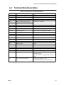
4.4
Terminal Strip Description
Table 4-1: Control Panel Terminal Descriptions
Name
Terminal Description
Electrical Ratings
AC
AC Input
18 VAC, 60 Hz, 50VA
AC
AC Input
18 VAC, 60 Hz, 50VA
EARTH
Earth Ground
0 VDC
N.O.
Relay Contact (Normally Open)
2.5 Amps max. @ 24VDC
COM
Relay Contact (Common)
Must be connected to power limited sources only
+12V
Accessory Power (+)
12 VDC, 1 Amp max.
+SMK
Smoke Detector Power (+)
12 VDC, 1 Amp max.
GND
Circuit Ground
0 VDC
EXT SPK
External Speaker (+)
8 ohm, 15 watt min. rating speaker output
INT1 SPK-
Internal Speaker #1 (-)
INT+
Internal Speaker (+)
INT2 SPK-
Internal Speaker #2 (-)
S2-
SBUS #2 (-)
0 VDC
S2+
SBUS #2 (+)
12 VDC, 1 Amp max.
A2
SBUS #2 (data)
5 VDC
B2
SBUS #2 (data)
5 VDC
S1-
SBUS #1 (-)
0 VDC
S1+
SBUS #1 (+)
12 VDC, 1 Amp max.
A1
SBUS #1 (data)
5 VDC
B1
SBUS #1 (data)
5 VDC
1
Zone 1 Input
12 VDC, 50mA max.
.079 VDC Nominal
(Note that this zone is rated differently from other
inputs.)
C+
Zones 1 and 2 Power Output
All zone power outputs: 12 VDC
(1) 8 ohm, 5 watt, or (3) 45 ohm, 1 watt
Use ESL Model 449CT 4-wire smoke detector.
150964
4-3
Model 4821/4820 Control/Communicator Installation Manual
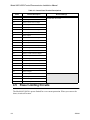
Table 4-1: Control Panel Terminal Descriptions
Name
Terminal Description
2
Zone 2 Input
3
Zone 3 Input
C+
Zones 3 and 4 Power Output
4
Zone 4 Input
5
Zone 5 Input
C+
Zones 5 and 6 Power Output
6
Zone 6 Input
7
Zone 7 Input
C+
Zones 7 and 8 Power Output
8
Zone 8 Input
9
Zone 9 Input
C+
Zones 9 and 10 Power Output
10
Zone 10 Input
11
Zone 11 Input
C+
Zones 11 and 12 Power Output
12
Zone 12 Input
13
Zone 13 Input
C+
Zones 13 and 14 Power Output
14
Zone 14 Input
15
Zone 15 Input
C+
Zones 15 and 16 Power Output
16
Zone 16 Input
T-RING
Telco Ring
T-TIP
Telco Tip
P-RING
Premises Ring
P-TIP
Premises Tip
4.5
Electrical Ratings
For zone 2-16 inputs:
12 VDC max. at 1.4 mA
Power Limiting Circuits
The Model 4821/4820 is power-limited for over-current protection. When you remove the
short, circuits self-restore.
4-4
150964
Control Panel Description and Installation
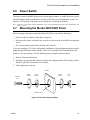
4.6
Power Switch
The power switch is disabled by the power switch bypass jumpers, to enable the power switch
cut both jumpers. Make sure the power switch is off when you are installing the system. See
Figure 4-1 for location of the power switch and power switch bypass jumpers.
Note: The power switch bypass jumpers can not be cut for UL 864 and NFPA (Chapter 4) fire installations. (See
Section 1.4.3.5.)
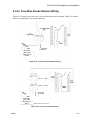
4.7
Mounting the Model 4821/4820 Panel
When selecting a location to mount the Model 4821/4820, consider the following:
•
Panel must be accessible to main drop wiring runs.
•
Panel must be located well within the secured area, but must be accessible for testing and
service.
•
See environmental specifications described in Section 4.1.
If you are installing a UL Grade A Mercantile installation, all unused knockout holes must be
plugged using bolts and washers. (Model 7600 is a kit available from Silent Knight for this
purpose. 6 sets per package.) Use the following steps to plug the knockout holes:
1. Remove all unused knockouts.
2. Install the carriage bolt and washers as shown in the diagram below. The smallest washer
should be placed inside the hole in the cabinet.
3. Firmly tighten the wing nut.
CABINET
CARRIAGE
LARGE
SMALL
LARGE
WASHER
WASHER
WASHER
WING
NUT
BOLT
KNOCKOUT HOLE
Figure 4-2 Knockout Plug Installation
150964
4-5
Model 4821/4820 Control/Communicator Installation Manual
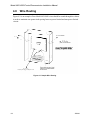
4.8
Wire Routing
Figure 4-3 is an example of how Model 4821/4820 wires should be routed through the cabinet
in order to maintain one-quarter inch spacing between power limited and non-power limited
circuits.
Figure 4-3 Sample Wire Routing
4-6
150964
Control Panel Description and Installation
4.9
Current Draw Worksheets
The current draw worksheets in this section are provided to help you calculate the number and
size of devices that will be used in an installation. Copy these sheets as needed.
Figure 4-4 and Figure 4-5 are sample worksheets. (They have already been filled out to serve
as examples.) Blank worksheets for your installations are in Sections 4.9.2 and 4.9.3.
4.9.1
Sample Worksheets
Figure 4-4 Sample Silent Knight Module Current Worksheet
150964
4-7
Model 4821/4820 Control/Communicator Installation Manual
Figure 4-5 Sample Compatible Module Current Worksheet
4-8
150964
Control Panel Description and Installation
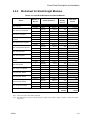
4.9.2
Worksheet for Silent Knight Modules
Table 4-2: Current Draw Worksheet for Optional Modules
Device
Model 4821/4820 Control/
Communicator
4421 Door Access Module
4860 Series Touchpad
4205 Touchpad (used with
the 4421)
4880 Status Output Module
4824 Serial/Parallel Interface
4815 Zone Expander
4825 Zone Expander
4875 Dual Phone Line
Monitor
4884 Bell Module
4300 Swipe Card Reader
4330 Proximity Reader
4340 Proximity Reader
4350 Proximity Reader
5211 Ground Start Relay
Number of
Devices
1
(1 max.)
(24 max.)
(24 max.)
(24 max.)
(3 max.)
(8 max.)
(3 max.)
(6 max.)
1
(1 max.)
1
(1 max.)
(24 max.)
(24 max.)
(24 max.)
(24 max.)
1
(1 max.)
Current per Device
Standby:
Alarm:
Standby
Alarm
Standby:
Alarm:
Standby:
Alarm:
Standby:
Alarm:
Standby:
Alarm:
Standby:
Alarm:
Standby:
Alarm:
Standby:
Alarm:
Standby:
Alarm:
Standby:
Alarm:
Standby:
Active:
Standby:
Active:
Standby:
Active:
Standby:
Alarm:
Subtotal of current ratings for Silent Knight devices
100 mA
120 mA
25 mA
40 mA
48 mA
90 mA
10 mA
10 mA
20 mA
140 mA
40 mA
40 mA
80 mA
80 mA
80 mA
80 mA
0 mA
18 mA
5 mA
60 mA
25 mA
25 mA
45 mA
80 mA
45 mA
80 mA
100 mA
150 mA
0 mA
18 mA
Total
Standby
Current
Total Alarm
Current
100 mA
120 mA
mA
mA
mA
mA
mA
mA
mA
mA
mA
mA
mA
mA
mA
mA
mA
mA
mA
mA
mA
mA
mA
mA
mA
mA
mA
mA
mA
mA
Standby
mA
mA
Alarm
Note: Total of all 4421s and 4860s combined.
Note: The 4884 shares its power with the auxiliary output. The auxiliary output is rated at 1A total current for
all devices.
150964
4-9
Model 4821/4820 Control/Communicator Installation Manual
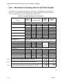
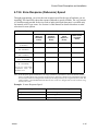
4.9.3
Worksheet for Auxiliary Devices (not Silent Knight)
Use Table 4-3 for recording current draw for other devices compatible with the 4821/4820
that are not manufactured by Silent Knight (for example, signaling devices and smoke detectors). Copy this page if you need additional lines to list devices.
Table 4-3: Current Draw Worksheet for Other Devices
Device
Smoke Detectors
Signaling Devices
Other Devices
Number of
Devices
Current per Device
Total
Standby
Current
Total Alarm
Current
Refer to device manual for current ratings.
Standby:
Alarm:
Standby:
Alarm:
Standby:
Alarm:
Standby:
Alarm:
Standby:
Alarm:
Refer to device manual for alarm
ways 0 mA.
mA
mA
mA
mA
mA
mA
mA
mA
mA
mA
current ratings.
mA
mA
mA
mA
mA
mA
mA
mA
mA
mA
Standby current is almA
mA
mA
mA
Alarm:
mA
Alarm:
mA
Alarm:
mA
Alarm:
mA
Refer to device manual for current ratings.
Standby:
Alarm:
Standby:
Alarm:
Standby:
Alarm:
mA
mA
mA
mA
mA
mA
mA
mA
mA
mA
mA
Row B
Subtotal current ratings of all devices in Table 4-3.
mA
Standby
mA
mA
Alarm
Row A
Subtotal current ratings of SK devices from Table 4-2.
mA
Standby
mA
Alarm
Row C
Total current ratings of all devices in system (Row A + Row B)
mA
Standby
mA
Alarm
4-10
150964
Control Panel Description and Installation
4.9.4
Battery Calculation Worksheet
To ensure 24-hour standby, the total standby current must not exceed:
285 mA if a battery only is used.
450 mA if the Model 4195 Auxiliary Power Supply is used.
Total alarm current must not exceed 2.25 Amps.
Table 4-4: Battery Calculation Worksheet
Device
4.9.5
A
Total current used by 4821/4820
(from Table 4-3, Row C)
B
Standby
Current
Alarm
Current
mA
mA
Total current ratings converted to amperes
(Line A x .001)
A
A
C
Number of standby hours (for example, 24)
H
D
Multiply lines B and C
E
Alarm sounding period in hours
(For example, 5 minutes = .084 hours)
F
Multiply lines B and E
G
Add lines D and F
AH
H
Multiply line G by 1.2
(Total ampere hours required)
AH
AH
H
AH
Standby Current For DACT Compliant Installations
In order to meet the 24-hour standby requirement the total standby current Must Not exceed
475mA for the system using both the 4821/4820 Control Panel and the 4195 Auxiliary Power
Supply. The combination of these supplies provides 14 amp hours of standby power.
If your system configuration exceeds 475 mA of standby current you must provide additional
power from an external power supply. Silent Knight has tested the following power supplies
for compatibility with the 4821/4820 Control Panel:
•
Alarm Saf
Model PS5-BFS-12-UL
•
Altronix
Model AL400ULX
150964
4-11
Model 4821/4820 Control/Communicator Installation Manual
4.10 AC Power Transformer
The Model 9227 is an external transformer that is included with the 4821/4820. The transformer output is 18 VAC, 50VA and provides power and battery charging for the system. The
transformer plugs directly into a conventional 120 VAC unswitched outlet.
The earth terminal on the 4821/4820 main circuit board provides a convenient method for
connecting the 4821/4820 metal cabinet to an earth ground. (See Figure 4-6.)The earth connection is also used for increased transient protection on the telephone interface. All circuitry
in the Model 4821/4820 system is electrically isolated from this earth terminal on the 4821/
4820 main circuit board. There should be no connections to this terminal other than the earth
connection for grounding the metal cabinet.
Figure 4-6 Model 9227 Connection to Model 4821/4820
4-12
150964
Control Panel Description and Installation
4.11 Backup Battery Connection
The Model 6712 is a 12 VDC 7AH gell cell battery available from Silent Knight for use with
the 4821/4820. (Note that the battery does not charge when system power is off.)
A low battery trouble condition exists if the battery voltage drops below 10.2 VDC.
The nominal charging voltage is 13.65 VDC (range is 13.5 to 14.0).
This manual contains a worksheet for determining battery size. See Section 4.9.4 for more
information.
Note: If you are installing a battery in a system that has a tamper switch, an alarm may occur when you install
the battery (because the door must be open when power is applied).
Figure 4-7 Model 6712 Battery Connection
150964
4-13
Model 4821/4820 Control/Communicator Installation Manual
4.12 4195 Auxiliary Power Supply Installation
Through its two 1.25A 12 VDC terminals, the 4195 provides an additional 2.5A of current for
accessory items. The 4195 also allows you to use two standby batteries to double the time that
the system can function on battery standby.
Figure 4-8 shows the location of LEDs for battery reversal and output overload. It also shows
how to wire the 4195. If you are using the 4195 to power smoke detectors, connect the 4195
CONTROL terminal to the 4821/4820 +SMK terminal. For powering other types of devices,
connect CONTROL to +12V.
Figure 4-8 Model 4195 Auxiliary Power Supply Connection
4-14
150964
Control Panel Description and Installation
4.13 SBUS
Most modules available for use with the 4821/4820 connect via a four-wire serial bus (SBUS).
There are two SBUS connections that are referred to in this manual as “SBUS1” and
“SBUS2”.
Each SBUS is a four-wire serial bus containing two power and two data conductors. The
power conductors are identified as S- (system ground) and S+ (+10 to +14 volts). The data
conductors are identified as A and B. Lines A and B are a differential RS485 pair.
All modules connected on the SBUS can be located as far as 4,000 feet from the control panel,
if sufficiently large wire gauges are used for the power and ground connections. The voltage
drop on the wire run must not be more than 2.0 volts. (See Section 4.13.3 for specifics.)
Figure 4-9 is a general picture of SBUS connection points. Wiring for each SBUS module is
shown in the appropriate section of this manual or in the separate manual for the device.
Figure 4-9 SBUS Connection Points
4.13.1 SBUS Modules
The following modules connect to the 4821/4820 via the SBUS:
•
Touchpads (Models 4421, 4860C, 4860R, and 4860Rx)
Note: 4421 cannot be used with the 4820 control panel
•
Zone Expanders (Models 4815 and 4825)
•
Status Output Module (Model 4880N-750-SDB)
•
Serial/Parallel Module (Model 4824)
Figure 4-10 shows an installation making use of all SBUS modules available with the Model
4821/4820 system. (For simplicity, the diagram shows all modules connected to a single
SBUS, though in a real application you would typically divide modules as evenly as possible
between SBUS1 and SBUS2.)
150964
4-15
Model 4821/4820 Control/Communicator Installation Manual
4.13.2 Distribution of Modules Between SBUS1 and SBUS2
SBUS modules can be distributed between the two serial buses in any combination.
Note: In a UL installation, each SBUS must have at least one touchpad.
Figure 4-10 Sample SBUS Connections
4-16
150964
Control Panel Description and Installation
4.13.3 Number of SBUS Devices
The table below shows the maximum number of devices and maximum distance from the
4821/4820 for SBUS devices, assuming a maximum of 2 volts of line drop and 100 mA of
current per device. Following these guidelines guarantees that there will be sufficient voltage
in the worst case (when the battery voltage is 10V or greater and when all devices are located
at the end of the wiring). (The formula used to generate this table is shown in the note below.)
Table 4-5: Number of SBUS Devices
Model 4821/4820 to SBUS Devices
Maximum wiring distance with 14 - 22 gauge wire (AWG)
Num. of Devices
per 4-Conductor Wire
22 Gauge
18 Gauge
16 Gauge
14 Gauge
1
617 ft.
1562 ft.
2487 ft.
3937 ft.
Max. distance for all
home-run devices.
2
308 ft.
781 ft.
1243 ft.
1968 ft.
Max. distance for 2 Ttapped or daisy-chained
devices.
3
205 ft.
520 ft.
829 ft.
1312 ft.
Max. distance for 3 Ttapped or daisy-chained
devices.
4
154 ft.
390 ft.
621 ft.
904 ft.
Max. distance for 4 Ttapped or daisy-chained
devices.
Note: The following formula was used to calculate the maximum wire distances:
Max. Distance = 500V
NIRpu
where:
V=
2 volts (Maximum allowed voltage drop under low battery condition of 10.0
volts.)
N=
Number of devices
I=
.1 amps (Worst case current draw for all devices.)
Rpu =
Ohms per 1,000 feet for various wire gauges, see below.
Wire gauge
150964
Ohms per 1,000 feet
22
16.2 Ω
18
6.4 Ω
16
4.02 Ω
14
2.54 Ω
4-17
Model 4821/4820 Control/Communicator Installation Manual
4.14 Touchpad Installation
This section describes installation of a touchpad for basic system operation. For information
about how to install 4860C touchpads as input zones, see Section 4.15.5.
4.14.1 Touchpad Specifications
•
When installed for use as an access control system the touchpad must be located inside the
protected premises.
•
24 touchpads/card readers maximum per system.
•
All touchpads require four wires to operate.
•
Maximum distance from the control panel depends on the number of devices attached to
the SBUS. See Section 4.13.3 for complete information.
•
Maximum current draw: 90 mA
•
Standby current draw: 48 mA
•
Maximum allowed voltage drop for a touchpad wire run: 2V
•
For best system performance, connect most touchpads to the same SBUS, either SBUS1
or SBUS2. (Connect all other SBUS devices to the SBUS that is not used by touchpads.)
4.14.2 Mounting Touchpads
1. Separate the top section from the rear mounting plate. Do this by inserting a small flatblade screwdriver into the slot located on the bottom edge of the frame. (See Figure 4-11.)
Push in, then lift up the top section.
Figure 4-11 Mounting Plate Slot location.
2. Secure the mounting plate to the wall using the screw (#6 or #8) appropriate for the type of
wall material.
3. The mounting plate should be oriented so that the protruding tab and the three posts are
towards the bottom. Pull the wires through the hole in the rear mounting plate.
4-18
150964
Control Panel Description and Installation
4. Wire the touchpad as described in Section 4.14.3.
5. After all the wires are connected to the touchpad terminal strip, set the top of the touchpad
frame over the tabs at the top of the mounting plate, then press on the bottom until you
hear it snap into position.
4.14.3 Wiring Touchpads
Figure 4-12 shows how to connect a Model 4860 touchpad to the 4821/4820.
Figure 4-12 Touchpad Wiring
150964
4-19
Model 4821/4820 Control/Communicator Installation Manual
4.15 Zone Installation
4.15.1 Zone Hardware Specifications
The chart below lists all input zone hardware types available with the 4821/4820 modules.
Hardware Module
Description
4821/4820
16 internal zones are built into the 4821/4820 main system board.
4825 Hardwire Zone Expander
Each 4825 adds up to 64 hardwire zones. These zones have all the same
features as 4821/4820 internal zones.
4815 Serial Zone Expander
Each 4815 adds up to 128 serial SmartSensor zones. The differences
between the SmartSensor zones and all other zones used in the 4821/4820
system are described in detail in the 4815 tabbed section of this binder
(part number 150909).
4860C Touchpad Zones
Two input zones are built into the 4860C touchpads. These zones have all
the same features as 4821/4820 internal zones (except that the fastest
response speed, 10 milliseconds) is not available. The installation is the
same as the 4821/4820 internal zones. See Sections 4.15.5 and 4.15.6.
Note: 4421 cannot be used with
the 4820 control panel.
Two input zones are built into the 4421. These zones have all the same
features as 4821/4820 internal zones (except that the fastest response
speed, 10 milliseconds) is not available. The installation is the same as the
4821/4820 internal zones.
4421 Door Access Module
4.15.2 Maximum Number of Zones per System
The maximum number of zones that can be connected to the 4821/4820 is 400.
These zones can be a combination of internal zones, 4815, 4825, 4421, and 4860C touchpad
zones.
4-20
150964
Control Panel Description and Installation
4.15.3 Zone Configuration
At any moment an input zone can be in one (and only one) of three states, depending on the
state of the hardware circuit connected to the zone input. The possible states are Open Circuit,
EOL Circuit, and Short Circuit. The value of the EOL resistor used on all input zones in the
4821/4820 system is 4.7k ohms (Silent Knight part number 7628). 4815 SmartSensor zones
are an exception because they require a 1.43k ohm resistor (Silent Knight model 4114).
Note: UL zones must be end-of-line supervised.
Figure 4-13 Zone States
Through programming, you determine how the zone will respond to the three possible states
when it is armed and disarmed. The possible system responses for all three states are Ready,
Not Ready, Trouble, or Alarm. See Section 4.15.4 for examples of typical zone wiring.
150964
4-21
Model 4821/4820 Control/Communicator Installation Manual
4.15.4 Zone Configuration Examples
The chart below shows some commonly used zone hardware configurations and provides
examples of how you might want to program the zone for the disarmed and armed responses.
UL zones must be end-of-line supervised.
Programmed
Disarmed Response
Programmed
Armed Response
Open Circuit
Contact open or open hardware fault.
Ready
Ready
EOL Circuit
(This state is not possible
for this example, but you
still must program a system response for this configuration.)
Not Ready
Alarm
Short Circuit
Contact closed or shorted
hardware fault.
Not Ready
Alarm
Open Circuit
Contact open or open hardware fault.
Not Ready
Alarm
EOL Circuit
(This state is not possible
for this example, but you
still must program a system response for this configuration.)
Not Ready
Alarm
Short Circuit
Contact closed or shorted
hardware fault.
Ready
Ready
State of Zone
4-22
150964
Control Panel Description and Installation
Programmed
Disarmed Response
Programmed
Armed Response
Trouble
Trouble
EOL Circuit
The contact is open and supervised.
Ready
Ready
Short Circuit
The contact is closed or
there is a short circuit hardware fault.
Alarm
Alarm
Open Circuit
The contact is open or
there is an open circuit
hardware fault.
Not Ready
Alarm
EOL Circuit
The contact is closed and
supervised.
Ready
Ready
Trouble
Alarm
State of Zone
Open Circuit
Open circuit
fault.
Short Circuit
Short circuit
fault.
150964
hardware
hardware
4-23
Model 4821/4820 Control/Communicator Installation Manual
Programmed
Disarmed Response
Programmed
Armed Response
Open Circuit
Open hardware fault or the
N.C. contact is open.
Not Ready
Alarm
EOL Circuit
The N.C. contact is closed
and the N.O. contact is
open.
Ready
Ready
Short Circuit
Both contacts are closed or
there is a shorted hardware
fault.
Trouble
Alarm
State of Zone
4.15.5 Wiring a 4860C as an Input Zone
Figure 4-14 is a back view of the 4860C touchpad showing the location of its two input zones.
These zones are wired and programmed the same as hardwire zones. See Section 4.15.6 for
available zone response speeds.
*Use Cable Assembly
P/N 130378N-750-INPT-
Figure 4-14 Location of 4860C Input Zones
4-24
150964
Control Panel Description and Installation
4.15.6 Zone Response (Debounce) Speed
Through programming, you select the zone response speed for the type of hardware you are
installing. The chart below shows the response (debounce) speeds available. The very fast rate
of 10 milliseconds (needed for devices such as audio glass break detectors) is available only
for internal or 4825 type zones. See Section 6 of this manual for details about how to make
selections for zone options.
Response Speed
Available with:
Internal
(Built into
4821/4820
board)
4825
(Hardwire
Expansion
Zones)
4815
(Serial
Expansion
Zones)
4860C & 4421
(Touchpad
Zones)
10 milliseconds
(9-18 msec)
Yes
Yes
No
No
100 milliseconds
(55 - 100 msec)
Yes
Yes
No
Yes
250 milliseconds
(220 - 330 msec)
No
No
Yes
No
1 second
(0.5 - 1.0 seconds)
Yes
Yes
Yes
Yes
10 seconds
(5 - 10 seconds)
Do not use with smoke
verification zones. See
Section 6.3.2.3.
Yes
Yes
Yes
Yes
Note: In the Response Speed column above, the range of numbers in parentheses shows the duration (milliseconds or seconds) that the zone response speed represents. The larger number is the minimum duration that
the zone must remain in a changed state in order for the change to always be recognized by the system. The
smaller number is the maximum duration that the zone can be in a changed state in order to not be recognized by the system.
Example: 10 msec Response Speed
If the zone change of state lasts:
150964
The zone state change is:
longer than 18 msec
ALWAYS recognized
shorter than 9 msec
NEVER recognized
between 9-18 msec
might be recognized, but NOT GUARANTEED
4-25
Model 4821/4820 Control/Communicator Installation Manual
4.16 Smoke Detector Wiring and Operation
Note: The Model 4821/4820 is not compatible with 2-wire smoke detectors.
4.16.1 Smoke Detector Compatibility
This section describes the 4821/4820 reset and smoke verification cycles. Any smoke detectors attached to the 4821/4820 must be compatible with the reset cycle. If you are using the
smoke verification feature, smoke detectors must also be compatible with the smoke verification cycle. See Section 4.16.1.1 for information about reset operation. See Section 6.3.2.3 for
information about programming the smoke verification option.
4.16.1.1 Smoke Reset Cycle
When you reset a smoke detector, power is off for 6 seconds. The system then applies a restart
time of 36 seconds. During the restart time, smoke power is reapplied and the zones are
allowed to stabilize. The system will not respond to fire zones during the reset period (but will
respond to other types of zones, including fire contact zones).
4.16.1.2 Smoke Verification Cycle
Smoke verification is a four-period cycle:
•
Retard Period
18 second delay after a zone is tripped before smoke detector power
turns off.
•
Reset Period
Smoke detector power is off for 6 seconds.
•
Restart Period
36 seconds for the smoke detectors to stabilize. The system will not
respond to fire zones during this time (but will respond to other
types of zones, including fire contact zones).
•
Confirmation Period 60 second period during which all zones will be considered instant.
If the zone trips a second time during this period, the zone will go
into alarm immediately.
Smoke verification will not occur if any fire zones are currently in alarm anywhere in the
same partition.
Note: Smoke verification is not compatible with the 10 second zone response (debounce) speed. See Section
6.3.2.3 for more information.
4-26
150964
Control Panel Description and Installation
4.16.2 Four-Wire Smoke Detector Wiring
Figure 4-15 shows how to wire one 4-wire smoke detector to the system. Figure 4-16 shows
how to wire multiple 4-wire smoke detectors.
Model 7628
EOL Resistor
Silent Knight
Model 160150
Relay Supervision
Module
Figure 4-15 Four-wire smoke detector wiring
Model 7628
EOL Resistor
Silent Knight
Model 160150
Relay Supervision
Module
Figure 4-16 Four-wire smoke detectors
150964
4-27
Model 4821/4820 Control/Communicator Installation Manual
4.17 Speaker Wiring
The 4821/4820 can be used with one external and two internal speaker outputs. In UL installations, a bell must be the primary source for alarm annunciation in UL burglary installations. In
UL burglary installations speakers can be used as an supplementary source only and are not
intended to be used for evacuation purposes.
4.17.1 Internal Speaker Wiring
Each internal speaker output can accept one 8 ohm, 5 watt speaker or three 45-ohm, 1 watt
speakers in parallel.
Figure 4-17 Internal Speaker Wiring
4.17.2 External Speaker Wiring
The external speaker output can accept one 8 ohm, 15 watt minimum speaker.
Figure 4-18 External Speaker Wiring
4-28
150964
Control Panel Description and Installation
4.18 Bell Wiring
A bell can be attached to the built-in relay on the 4821/4820 and is factory-programmed for
this purpose. A programmable I/O script drives the relay. The script must not be deleted. See
the Model 5580 Download Software Installation and Operation Manual (P/N 150925) for
information about how to select the script.
4.18.1 Residential Type Bell Wiring
The configuration shown in Figure 4-19 is for residential use.
Figure 4-19 Bell Wiring for Residential Use
150964
4-29
Model 4821/4820 Control/Communicator Installation Manual
4.18.2 Commercial Bell Wiring
A bell can be attached to the built-in relay on the 4821/4820 and is factory-programmed for
this purpose. If you are installing a UL commercial burglary system, you must use an Ademco
AB12 Bell and Box bell and enclosure. Wire as shown in Figure 4-20.
Figure 4-20 Commercial Bell Wiring
4-30
150964
Control Panel Description and Installation
4.19 4884 Bell Module wiring
The 4884 is plugged directly onto the P2 connector on the 4821/4820 Control Panel. (Refer to
Figure 4-21 for placement of 4884 Bell Module on P2 connector.)
Figure 4-21 Generic Bell Wiring to 4884 Bell Module and Placement on P2
When using the 4884 with the 4821/4820 Control Panel the Bell Cadence option is set to
ANSI. (See Section 6.3.1.1 for information on how to set bell cadence.)
150964
4-31
Model 4821/4820 Control/Communicator Installation Manual
4.20 Telephone Line Connection
Connect the 4821/4820 to the telephone line using an RJ31X cord. Silent Knight’s Model
7860 is available for this purpose. Connect as shown in Figure 4-22.
Figure 4-22 Telephone Line Connection
Note: To comply with industry standards, this product is equipped with line seizure. Any time the system’s dialer
needs to communicate with the central station, it will not be possible to use any telephones that are on the
same line(s) as the system. Normally this condition will last approximately one minute, but under adverse
telephone conditions, could last for as long as 15 minutes.
4-32
150964
Control Panel Description and Installation
4.20.1 Second Phone Line Monitor Connection (Model
4875)
The 4875 provides a second phone line connection. It includes the line monitor and ring detector for the second line.
Figure 4-23 Location of Dual Phone Line Monitor (Model 4875) on Model 4821/4820 Board
Table 4-6: Second Phone Line Monitor Terminal Description
Pin Number
150964
Description
1
Circuit Ground
2
+12 VDC
3
Monitor 2
4
Report Relay
5
Power Phone Line 2 Relay
6
Phone Power
7
Circuit Ground
8
Earth Ground
9
Line 2 Tip
10
Line 2 Ring
4-33
Model 4821/4820 Control/Communicator Installation Manual
4.20.2 Ground Start Relay Connection (Model 5211)
Figure 4-24 shows the position of the relay that is required if the ground start telephone network is used.
Note: Ground start cannot be used in UL installations.
Figure 4-24 Location of Ground Start Relay (Model 5211) on Model 4821/4820 Board
4.21 Built-in Relay
The 4821/4820 board provides contacts for one Normally Open relay rated at 2.5A at 24
VDC.
This relay can be used to activate a variety of devices and can be used in combination with
programmable I/O statements. See the I/O Application Programming section of this binder
(P/N 150913) for more information.
This relay is factory-programmed as the bell circuit.
Figure 4-25 Location of Model 4821/4820 On-Board Relay
4-34
150964
Control Panel Description and Installation
4.22 DACT Compliant Wiring
The following sections contain diagrams and information necessary for installations to comply with UL 864 and NFPA 72 (Chapter 4) fire alarm systems for central station services.
4.22.1 Trouble Output Relay
A trouble output relay for each power supply, must be connected to a zone input on the 4821/
4820 Control Panel (see Figure 4-26). The “Zone Type” should be selected as Tamper and the
response characteristics as follows:
Table 4-7: Trouble Output Relay Response Characteristics
Disarmed Response
Armed Response
Short
Trouble
Trouble
EOL
Ready
Ready
Open
Trouble
Trouble
Model 7628
EOL Resistor
Figure 4-26 Wiring Diagram For a Power Supply Trouble Fault Relay
150964
4-35
Model 4821/4820 Control/Communicator Installation Manual
4.22.2 Monitoring an Existing Fire Alarm Control
Separate zone connections must be made to both the alarm relay and trouble relay when using
the 4821/4820 Control Panel to monitor an existing fire alarm control. Zone inputs on the
4821/4820 Control Panel are considered Class B (Style A). Refer to Figure 4-27 and Table 48 for wiring configuration and zone programming requirements.
Model 7628
EOL Resistor
Figure 4-27 Wiring configuration for Alarm Relay and Trouble Relay
Table 4-8: Alarm and Trouble Relay Zone Programming Requirements
Alarm Relay
Trouble Relay
Disarmed Response
Armed Response
Disarmed Response
Armed Response
Short
Alarm
Alarm
Trouble
Trouble
EOL
Ready
Ready
Ready
Ready
Open
Trouble
Trouble
Trouble
Trouble
Zone Type
4-36
Fire
Fire
150964
Control Panel Description and Installation
4.22.3 Monitoring A Sprinkler System
Separate zone connections must be made to both the waterflow switch and water shut off
valve when using the 4821/4820 to monitor a sprinkler system. Zone inputs on the 4821/4820
Control Panel are considered Class B (Style A). Refer to Figure 4-28 and Table 4-9 for wiring
configuration and zone programming requirements.
Model 7628
EOL Resistor
Figure 4-28 Wiring Necessary for Monitoring a Sprinkler System
Table 4-9: Waterflow Switch and Water Shut Off Valve Zone Programming Requirements
Waterflow Switch
Water Shut Off Valve
Disarmed Response
Armed Response
Disarmed Response
Armed Response
Short
Alarm
Alarm
Alarm
Alarm
EOL
Ready
Ready
Ready
Ready
Open
Trouble
Trouble
Trouble
Trouble
Zone Type
Sprinkler
Sprinkler Supervisory
Note: The Sprinkler Supervisory zone type will display “supervisory”, and the Sprinkler zone type will display
“fire” on the 4860 touchpad display, when in the alarm state.
150964
4-37
Model 4821/4820 Control/Communicator Installation Manual
4-38
150964
Section 5
System Operation
5.1
Partitions and Areas
Software partitions and areas are optional features that allow you to configure the system for a
high degree of flexibility.
The 4821/4820 can be sub-divided into multiple partitions, each of which can operate as independent systems. Each 4821/4820 system can have as many as 8 partitions, and each can
report to the central station as separate accounts. Touchpads and zones can be assigned to only
one partition.
Note: If you are installing a UL listed application, see Section 1.4.3 for UL requirements regarding partitions.
End-users and the central station may use their partition without being aware that other partitions exist (see). Partitioned systems do, however, share the following system resources:
Telephone lines
Telephone lines and programmable options that affect general
operation of telephones.
Sirens (or bells)
By default, sirens (or bells) are global features of the 4821/
4820. This means that a siren occurring in one partition would
output in all partitions. Siren/bell output can be controlled
individually through use of the optional 4880N-750-SDB Status OutputDisplay Module and programmable I/O. See the
4880N-750-SDB Installation Manual, P/N 150912TD1082
for more information.
General system operation
Other operational features that affect the general operation of
the system, such as system power-up mode, are considered
system-level.
These options are described in greater detail in Section 6.3.1.1.
For controlling access within a system, partitions can be further sub-divided into as many as 8
areas. End-users may be aware that other areas exist within the partition, but they may not
have access to those areas. While partitions report as separate accounts to the central station;
areas do not. Areas, however, can share touchpads and zones.
Figure 5-1 (next page) illustrates the concept of partitions and areas.
150965
5-1
Model 4821/4820 Control/Communicator Installation Manual
Figure 5-1 Partitioning
The sample applications shown in Figure 5-2 and Figure 5-3 are not acceptable UL applications. See Section 1.4.3 for UL requirements regarding partitions.
Figure 5-2 Sample Commercial Application Using Partitioning
5-2
150965
System Operation
Figure 5-3 Sample Residential Application Using Partitioning
150965
5-3
Model 4821/4820 Control/Communicator Installation Manual
5.2
Touchpad Models
The touchpads shown in Figure 5-4 can be used with the 4821/4820.
Figure 5-4 Model 4860C Commercial LCD Touchpad, Model 4205 Slimline Door Access Touchpad
and Model 4860R (for Residential burglary. and Fire Installations)
Note: The Model 4205 Slimeline Door Access Touchpad cannot be used with the 4820 control Panel. The Model
4205 is not UL listed for access control.
5-4
150965
System Operation
5.3
Display Messages
This section of the manual shows the types of system messages that display on the touchpad.
See Troubleshooting (Section 8) for system trouble messages.
5.3.1
Power Up Messages
The panel initializes itself when power is turned on and when downloading occurs. Figure 5-1
shows the types of messages that display on a touchpad during the panel’s initialization routine.
&6LOHQW.QLJKW
%XV
Figure 5-1 System Initialization Messages (Example)
150965
5-5
Model 4821/4820 Control/Communicator Installation Manual
5.3.2
Normal Display Messages
Two 2-line messages alternate on the LCD when the system is inactive. These messages display on all touchpads. Through programming, you can customize the messages for each partition (see Section 6.3.2.1).
Figure 5-1 Example Normal Display Messages
5.3.3
System Status Messages
Figure 5-1 and Figure 5-2 are examples of messages the system will display when active.
Figure 5-1 Example Status Display Message (Single-Area Menu System)
Figure 5-2 Example Status Display Message (Multi-Area Menu System)
5-6
150965
System Operation
5.4
Touchpad Buttons
Table 5-1 describes the functions of the touchpad buttons. The operation of the feature
depends on the type of menu system (toggle or interactive) that is being used and whether the
system is single- or multi-area. See Section 5.5 for more information.
Table 5-1: Touchpad Function Buttons
Key
Normal Mode Function
DLY
Activates/deactivates interior zones.
INT
0
-
Toggles zone status between delayed and instant. If the system is armed and the No Delay
LED is on, zones programmed for entry and exit delay will be instant.
9
Enter data. Used primarily for entering access codes.
9
STAT
BYPS
MEM
CODE 2
MUTE
CHM
CLR
0
is used to turn the system OFF and
is used to turn the system ON.
View system status. Displays active alarms and trouble conditions. Also displays not ready
zones.
This key is used to bypass individual zones and to check which zones have been bypassed.
Displays event history.
Allows Code 2 users to arm or disarm the system.
Silences alarm and trouble audio at speakers and touchpads.
Controls whether or not a chime tone will be generated when someone trips a chime zone
while the system is disarmed.
Erases a mistake made while entering a code or command.
ENTR
Conducts a variety of tests (see Section 5.9 for descriptions of the tests). In programming
mode, accepts programming changes. Also used to exit interactive menus.
POL
Police emergency key. If enabled through programming, transmits an alarm to the central
station personnel who then dispatch the police. This key must be held for one full second.
FIRE
AUX
DOOR
ICOM
TEL
150965
Fire emergency key. If enabled through programming, transmits an alarm to the central
station personnel who then dispatch the fire department. This key must be held for one full
second.
Auxiliary emergency key. If enabled through programming, transmits a special alarm to the
central station personnel who then dispatch the proper authorities. This key must be held for
one full second.
For door access (appears on 4860C and 4205 touchpads only).
This non-functioning key is reserved for future use.
This non-functioning key is reserved for future use.
5-7
Model 4821/4820 Control/Communicator Installation Manual
5.5
Toggle and Interactive Menu Operations
The 4821/4820 has two operational modes available to all users:
•
Interactive Menus: Menu prompts guide users through operation.
•
Toggle Operation: Pressing the appropriate key on the touchpad turns the feature on/off in
all areas that the user has access to. (There are exceptions to this. See Section 5.7 for more
information.)
•
Toggle operation is not the same in single- and multi-areas. In a single-area system, you
can toggle a feature on or off with one button. In a multi-area system, you must first select
areas.
End-user operation is fully described in the 4821 Owner’s Manual (P/N 150952) or the Census 4820 Owner’s Manual (P/N 150842 for residential P/N 150843 for commercial).
5-8
150965
System Operation
5.6
Interactive Menu Overview
The general structure of the interactive menu system is shown below. Available options will
vary depending on whether optional features have been enabled through programming for the
area. The chart below shows all available options.
Main Menu
To
Press
Enter/exit the menu.
Enter a code to enter; press
Select an area.
ENTR
to exit.
Enter area number (1-8). Options available for that area display.
(See sub-menu section below.)
Arm all areas.
Press
Disarm/reset all areas.
Press
Mute all trouble conditions.
Press
View status of system.
Press
9
0
Turns the system ON.
Turns the system OFF.
MUTE
STAT
.
.
Interactive Sub-Menu (displays when you select an area)
To:
Disarm/Reset this Area
Arm this Area
Set Arm Time
Set Delay
Press
From here you can press:
0
9
1
DLY
9
0
Set Interior
INT
- Make Instant
- Use Delays
1. Select the interior you wish to control (if both interiors used).
2. Press
Set Chime
CHM
9
0
See Current Status of
System
Bypass Menu
to turn Interior On or
0
to turn Interior Off
- Chime On
- Chime Off
STAT
BYPS
0
1
2
150965
9
- Bypass Status
- Bypass a Zone
- Unbypass a Zone
Select the zone # then press
ENTR
5-9
Model 4821/4820 Control/Communicator Installation Manual
5.7
System Operation Summary
Note: If you are using a profile that has not been restricted to a single partition, you will be prompted to select
the partition after you enter your access code.
Table 5-2: System Operation Summary
Steps
To
Interactive Menu Method
Arm/disarm entire system
or specific areas
Set Arm Delay Time/
Cancel Next Arming
Toggle Method
1. Enter a code to activate the menu.
Single area system:
2. Select the option that you want to perform. The Enter a code.
available options will vary depending on the
Multi-area system:
options enabled for the profile.
1
Enter a code to activate the menu.
2.
Select the option that you want to perform. The
available options will vary depending on the
options enabled for the profile.
Not available.
1. Enter a code to activate the menu.
2. Press
1.
.
3. To set the time: Enter the number of minutes
then press
ENTR
.
4. To cancel the next arming: Press
5. Press
ENTR
0
CLR
.
to exit.
Bypass a zone
1. Enter a code to activate the menu.
1. Press # of zone to bypass.
(Zones must be
programmed as
bypassable.)
2. Enter the area number of the area where the
zone you want to bypass is located.
2. Press
3. Press
4. Press
BYPS
1
5-10
Example:
to bypass a zone.
ENTR
.
3. Enter your code if prompted.
to enter the Bypass Menu.
5. Enter the zone number and press
6. Press
BYPS
To bypass Zone 2, press
ENTR
2
BYPS
.
.
to exit the Bypass Menu.
150965
System Operation
Table 5-2: System Operation Summary
Steps
To
Interactive Menu Method
Toggle Method
Reinstate (or unbypass) a
bypassed zone
1.
Enter a code to activate the menu and, if
prompted, select the partition.
1.
Press # of zone to reinstate.
A zone cannot be
reinstated if reinstating
will cause an alarm.
2.
Enter the number of the area where the zone you
want to reinstate is located.
2.
Press
3.
Enter your code if prompted.
Activate/Deactivate Chime
Feature
Activate/Deactivate Code
2 Feature
Manually Enable/Disable
Interior Feature
(if not programmed for
automatic interior)
150965
BYPS
3.
Press
4.
Press
5.
Enter zone number and press
6.
Press
1.
Enter a code to activate the menu and, if
prompted, select the area.
2
to reinstate a zone.
CHM
ENTR
.
to exit the Bypass Menu.
2.
Press
3.
9
0
Press
to turn on the chime feature or press
to turn off.
4.
Press
1.
Enter a code to activate the menu and, if
prompted, select the area.
ENTR
CODE 2
3.
Press
4.
Press
1.
Enter a code to activate the menu and, if
prompted, select the area.
Press
3.
Press
4.
Press
CHM
.
to exit.
Press
[Code].
to enable or
MUTE
Press
.
2.
2.
.
to enter the Bypass Menu.
ENTR
9
BYPS
0
to disable.
1.
Press
2.
Press
3.
Press
CODE 2
9
+ code.
to enable or
MUTE
0
to disable.
to exit.
to exit.
Press
INT
.
INT
9
to enable or
ENTR
0
to disable.
to exit.
5-11
Model 4821/4820 Control/Communicator Installation Manual
Table 5-2: System Operation Summary
Steps
To
Interactive Menu Method
Set System Time
1
1.
ENTR
Toggle Method
+ Maintenance or Installer Code.
1
2.
At the menu prompt, enter
to select “Time”.
3.
Enter digit(s) for hour in 24-hour military format, then press
4.
Enter digit(s) for minute, then
ENTR
ENTR
.
.
Note that if the “Auto DST Adjustment” feature has been enabled, the user will see a message when
setting the time.
EXAMPLE:
To change the system time to 3:45 p.m., the keystrokes are:
1
ENTR
1
5
ENTR
4
5
ENTR
Set system date
1
1.
1
+ code +
ENTR
+ Maintenance or Installer Code.
2
2.
At the menu prompt, enter
to select “Date”.
3.
Enter digit(s) for month, then press
4.
Enter digit(s) for date, then press
5.
Enter four digits for year, then press
ENTR
ENTR
.
.
ENTR
.
EXAMPLE:
To change the system date to June 21, 1996, the keystrokes are:
1
ENTR
6
ENTR
2
1
ENTR
1
9
9
[Code]
6
2
ENTR
Note: Valid range for the year is 1900 - 2155. If you enter a number outside the range, you will receive an error message. The day of the week is set automatically.
5-12
150965
System Operation
Table 5-2: System Operation Summary
Steps
To
Interactive Menu Method
Select Aux Menu item
2
1.
2.
ENTR
Toggle Method
+ Normal user code (or higher).
Select item from menu (0-9).
Note: Additional information about Aux Menu Items can be found in “5580 Installation and Operation Manual” P/N 150925, Section 3.
View status of system
From the main menu, press
View all zones touchpad
has access to
Press
View event history
Press
Press
1
STAT
MEM
1
STAT
.
.
[Installer Code]. A scrolling menu displays.
to see Alarm Events.
The system will scroll through a list of alarms that have occurred since the last time events were cleared.
Press
2
to Clear Alarm Events.
Clears alarm events (does not clear all events in event history). (In a multi-partition system, clears only
alarm events that have occurred in partitions you have access to.)
3
Press
to see History Events. History events include all events that occurred in partitions to which
you have access and any system events. The system will prompt you to enter a starting date. Enter the
date in mm/dd/yy format.
• Press
• Press
MUTE
to see all events in history.
ENTR
to move through the list of events.
STAT
• Press
to view additional information about the event (for example, user number or zone
number, if applicable).
Press
MUTE
to exit.
Note: You cannot manually clear all events in history. All events clear automatically when the panel
is powered down.
View revision level of the
4821/4820 operating
system
Activate a Duress
(Holdup) Alarm
Press
4
.
Displays the revision date and time.
Press 2 digits assigned as duress digits, then enter your access code.
Activate Emergency Keys
Press
FIRE
Conduct a System Test
150965
STAT
3
,
POL
ENTR
or
AUX
as needed. Hold for one full second.
1.
Press
+ Maintenance code or Installer code.
2.
Select the test you want to conduct from the menu that displays. (See Section 5.9 for descriptions of the tests.
5-13
Model 4821/4820 Control/Communicator Installation Manual
5.8
System Maintenance Operations Summary
The operations described in the chart below are intended to be performed by the person(s)
responsible for installing and maintaining the system. Access privilege rights needed to operate the function are indicated in the chart. See Section 6.3.5 for an explanation of the various
types of access rights.
To
Test System
Press
3
ENTR
See Section 5.9 for
descriptions of the tests.
[Maintenance or Installer Code]
From Here You Can Press
0
1
2
3
4
- Wlk Tst no Rprt
- Wlk Tst w/Rprt
- End Walk Test
- Do Dialer Test
- Dialer Reset
MUTE
Send Data to/from the Panel
4
ENTR
[Maintenance or Installer Code]
1
2
3
- Exit Menu
- Internal Phone
- 4824 Modem
- 4824 Direct
MUTE
- Exit Menu
See Section 5.10 for explanations
of these options.
Show Devices
Devices display in the order
they were added to the
system.
5
ENTR
[Maintenance or Installer Code]
1
2
3
4
5
6
- Touchpads
- 4824s)
- 4815s)
- 4825s)
- 4880
- All types.
MUTE
5-14
- Exit Menu
150965
System Operation
To
Diagnostics
Press
6
ENTR
7
ENTR
For Model 4815 Serial Zone
Expander.
Add or delete users from the
touchpad
[Maintenance or Installer Code]
From Here You Can Press
See the 4815 Installation Manual,
P/N 150909, for information about
these options.
1.
Enter the ID at the prompt. (This
is the number of the user, not the
access code.)
2.
Enter the number of the profile to
be used with this user. (Range
from 1-9999.)
3.
Enter the access code for this
user.
4.
At the Swipe / Type Card
display, enter the encoded card
PIN or present the card to the
[Maintenance or Installer Code]
reader and press
5.
Program System
8
ENTR
[Installer Code]
Press
MUTE
ENTR
.
to exit.
Brings up a menu for programming
system options. See Section 6.2.2.2
for more information.
The recommended method of
programming is through the 5580
Upload-Download Software.
Program Sensor
This menu is for
programming SmartSensors
used with the 4815 Serial
Zone Expander.
150965
9
ENTR
[Installer Code]
See the 4815 Installation Manual,
P/N 150909, for information about
these options.
5-15
Model 4821/4820 Control/Communicator Installation Manual
5.9
System Test Descriptions
This section describes the walk and dialer tests and dialer reset operation in detail. See Section
5.8 for instructions about how to run the tests.
5.9.1
Walk Test
The 4821/4820 can perform two types of walk tests, 1) walk test with report and 2) walk test
without report.
•
When a Walk Test without Report is executed, central station reporting is disabled. The
system reports a “Test Start” event, but no alarms or other events will be reported until the
end of the walk test.
•
When a Walk Test with Report is executed, central station reporting continues to operate
normally according to the individual account set up.
During a walk test, the audio alarm shutdown is defaulted to two seconds. This allows the
installer to arm the panel and then trip each zone in turn. As each zone is tripped, the speaker
output will sound for two seconds and then shut down. This is true for all zones, including
those that have been programmed not to allow bell shutdown. All zones will be allowed to
restore two seconds after they go into alarm.
The Walk Test times out after 15 minutes. When the test is being conducted, the message
WALK TEST ACTIVE
___ sec to go
displays on the LCD. The second line indicates the number of seconds before timeout occurs.
You can end the walk test manually by selecting option 2 “End Walk Test” from the Walk
Test menu.
5.9.2
Dialer Test
When the dialer test executes, a single test report is sent to each account that has been programmed as Must Report for test events.
5.9.3
Dialer Reset
When a dialer reset is conducted, all reporting is immediately aborted. All events (including
those that have not yet been reported) are cleared. The dialer remains enabled and will report
any events that occur after the reset.
5-16
150965
System Operation
5.10 Communicating with the Computer
This section of the manual describes communication initiated by the panel. See the 5580
Upload-Download Installation and Operation Manual (P/N 150925) for information about
communication initiated by the computer.
If you are using the 4824 or phone lines to communicate, communication may be initiated
from either the panel or the computer.
•
If a Requested Download or Requested Upload task is on the 5580 queue, you can process
the task from the panel. Follow the steps in Section 5.10.1.
•
If more than one task for the same account is on the queue, all tasks will be processed
starting with the task at the top of the queue (the “oldest” task). The 5580 processes tasks
in the order first in, first out.
•
If no task for the account is on the 5580 queue, you can send an Unsolicited Upload. Follow the steps in Section 5.10.1. An “Unsolicited Upload” task will appear on the 5580
queue.
•
If the computer running the 5580 software has been set up to not accept unsolicited
uploads, the upload will occur, but the uploaded information is not retained. Instead, a
“Called” task will appear on the queue, notifying the 5580 operator that the panel
attempted to upload.
150965
5-17
Model 4821/4820 Control/Communicator Installation Manual
5.10.1 Sending Data To and From the Panel
1. Press
4
ENTR
[Maintenance or Installer Access Code].
2. At the menu, select:
1
- Internal Phone.This option is for downloading via the phone lines.
2
- 4824 Modem.
With this type of communication, a Hayes compatible modem
is connected to both the 4824 and the PC, allowing for faster
data transmission.
3
- 4824 Direct.
This option is for directly connecting the 4824 to the computer
using a null modem cable (both the computer and the 4821/
4820 are on-site).
3. If you select either 4824 option (2 or 3), you will be prompted to select the 4824 from the
list of 4824s installed in the system.
4. If the phone number that displays is not correct, enter the correct digits and press
ENTR
.
(If the phone number is correct, press ENTR to bypass this step.) If you have selected the
4824 Direct option, this step will not appear.
5. If the Account number that displays is not correct, enter the correct digits and press
ENTR
. (If the account number is correct, press
ENTR
to bypass this step.)
6. The system will attempt to communicate. A series of messages indicating that the panel is
re-initializing will display. Do not attempt to power down the panel during re-initialization. When re-initialization is completed, the touchpad will display the current date and
time. (See Section 5.3.1 if you need more information about the messages that display during initialization.)
If the communication attempt was successful, the message “Ending Remote Communication”
displays on the LCD.
If your transfer attempt was unsuccessful, see Troubleshooting (Section 8) of this manual for
help in diagnosing the problem. See also the manual for the 5580 upload-download software
(P/N 150925) for information about communication problems.
Note: When the panel has been programmed to report System Events, the messages “Remote Program Success”
or “Remote Program Fail” are sent to the receiver.
5-18
150965
System Operation
5.11 Audible Signals Description and How to Reset
Alarm and trouble condition audible signals are listed below in priority order.
Condition
Fire Alarm
Speaker Sound
Bell Sound
Rapid high-low siren sound.
Each high-low sound lasts
approximately one halfsecond.
1 second on, one second off.
Note: This is programmable
through bell cadence
option. (See Section 6
Table 6-4 for Bell Cadence Options)
How to Silence/Reset
MUTE
To silence: Press
and enter your code.
To reset: Enter your code
and press
0
.
See Note 1 below.
Note 1:When you reset a fire alarm, displays and speakers shut down while the alarm is resetting (approximately 42 seconds to allow smoke detectors to reset). During this time the system will not respond to fire
zones (this does not apply to zones programmed as fire contact). If the alarm condition is still present
after the reset is completed, the displays and speakers will reactivate. See Section 4.16.1 for smoke
detector compatibility information.
When you reset an alarm in a 24-hour non-fire zone, speakers and displays shut down for five seconds. If the alarm is still present after five seconds, the speakers and displays will reactivate.
Intrusion Alarm
Loud whoop sound; 3
whoops per second.
Steady.
MUTE
To silence: Press
and enter your code.
To reset: Enter your code
and press
Emergency Alarm
Slow, high-low siren sound.
Each high-low sound lasts
approximately six seconds.
0
.
Steady.
MUTE
To silence: Press
and enter your code.
To reset: Enter your code
and press
Auxiliary Alarm
Low-high siren sound.
0
.
Steady.
MUTE
To silence: Press
and enter your code.
To reset: Enter your code
and press
Cross Alarm Alert
0
Three short beeps; repeats
every 2.5 seconds.
Not applicable.
Exit Delay
Low pitch bell (or “ding”)
sound.
Not applicable.
Enter a code.
Entry Delay
High pitch bell (or “ding”)
sound.
Not applicable.
Enter a code.
150965
.
0
to
Enter a code and press
stop the warning sound that
occurs when only one of the
cross alarm zones has been
tripped.
5-19
Model 4821/4820 Control/Communicator Installation Manual
Condition
Trouble
Speaker Sound
Two short, low-pitch beeps.
Bell Sound
How to Silence/Reset
Not applicable.
Press
MUTE
Doorbell 1
Slow two-tone (“dingdong”) bell sound.
Not applicable.
Not applicable.
Doorbell 2
Slow bell (“ding”) sound.
Not applicable.
Not applicable.
Ready and Not
Ready Chimes
Two quarter-second chime
tones.
Not applicable.
Not applicable.
Audio Test
Loud whoop sound for two
seconds on internal and
external speakers.
Steady.
Not applicable.
5-20
[Code].
150965
Section 6
Programming
This section of the manual describes all programmable options. The 4821/4820 can be programmed via the touchpad (see Section 6.2) or through the 5580 Upload-Download software
(see Section 6.1).
If you are using the 5580, you can send the options to the panel from a remote site or through
a portable computer (laptop) at the customer site. Refer to Model 5580 Upload-Download
Software Installation and Operation Manual (P/N 150925) for more information about
remote communication with a panel. See the 4824 tabbed section of this binder (P/N 150911)
for more information about sending data to the computer from a laptop on the customer site.
A complete functional test of the system is required following any remote programming
or reprogramming of the system.
6.1
Downloading
The Model 5580 Upload-Download Software must be used to program the 4821/4820 from a
remote site.
The 5580 software is organized into menus. As you move through the menus, the screens tell
you how to select options. Refer to Model 5580 Upload-Download Software Installation and
Operation Manual (P/N 150925) for more information.
6.2
Touchpad Programming
You can program some panel features from the touchpad. Because of the complexity of the
system and the vast amount of options available, touchpad programming is limited to the most
frequently used options. You must use the 5580 Upload-Download Software for programming
your system.
6.2.1
General Operation
Within each touchpad programming menu, the selections that are currently available cycle on
the second line of the LCD. The touchpad cycles through the options until you choose one.
Selections are shown in the following format:
@bUcc dXYc
d_ `UbV_b] dXYc QSdY_^
d_eSX`QT Redd_^
_b ]Q[U dXYc cU\USdY_^
MUTE-Exit Menu
150966
6-1
Model 4821/4820 Control/Communicator Installation Manual
You can use the editing keys as described in Table 1 for programming.
Table 6-1: Touchpad Programming Editing Keys
Key
Description
MUTE
Press this button to return to the main menu or to the previous level. A prompt will display
for you to confirm the changes made in the editing session.
0
The system will prompt you for saving changes. Press 0 to exit the current menu without
saving changes.
9
The system will prompt you for saving changes. Press 9 to save changes and exit the
current menu.
ENTR
Press this button to see additional options for the current menu.
When you successfully complete a task, the system will sound a tone and momentarily display
the message SUCCESS on the LCD.
6.2.2
The Main Menu
To access the main menu, press
following selections:
8
ENTR
[Installer’s Code]. The touchpad cycles through the
1-Install Device
4-Edit Ph. Lines
7-Edit Profiles
2-Edit Sys. Opt.
5-Reprt Accounts
8-Edit Schedules
3-Edit Partition
6-Print Accounts
9-Delete Options
You can choose a selection at any time during the cycle by pressing the number associated
with the selection on the touchpad.
To exit touchpad programming, press the
6-2
MUTE
button.
150966
Programming
6.2.2.1 1-Install Device
From the main menu, press
1
to access the Install Device menu.
This menu selection allows you to install or replace SBUS expansion devices. Before using
this selection, connect the new device(s) to the SBUS and re-apply the system power. The
options for the device can be downloaded using the 5580 software with the device serial number set to 0.
The first prompt that you see asks for the device you want to install.
Table 6-2: Device Types and Their Corresponding Number
Number
Choice
Device
1
Touchpads
2
4824s)
(For N-750-PIs)
3
4815s)
4
4825s)
5
4880
6
All types
Available device types cycle on the second line of your LCD. Devices are listed by serial
number.
The second prompt asks for a system configuration that is applied to the selected device. This
procedure is repeated for each new device.
6.2.2.2 2-Edit System Options
From the main menu, press
2
to edit access the following system options:
Account Number
Enter the computer account number.
Computer Phone Number
This is the number that the panel dials to contact the downloading computer. See
Section 6.3.1.1 for information about how to select characters.
Access Code
Enter a 4-to-8 digit computer security code. The default is 123456.
Call Back
Press 9 to enable the panel to call back the downloading computer after the initial
contact is made. Press 0 to disable call back.
150966
6-3
Model 4821/4820 Control/Communicator Installation Manual
6.2.2.3 3-Edit Partition
From the main menu, press
Select Partition
3
for editing selected partition options.
Select the partition to edit.
Menu Rate
Press
9
to make the menus scroll faster. Press
9
0
to make the menu scroll
0
slower. Each time you press
or
, the menu scroll rate changes by 0.25
seconds. Valid scroll rates are 0.5-10 seconds.
Menu Timeout
Select the time in seconds (5-120) that is allowed in an interactive menu.
Anti-Passback
Enables or disables the partition door access anti-passback feature.Press
to enable or
0
9
to disable.
6.2.2.4 4-Edit Ph. Lines
From the main menu, press
Select Line
Answering
Machine Bypass
Answer Ring
to edit the internal phone line options.
Selects which line to edit from either Line 1 or 2. If Line 1 or 2 is
programmed as unused in the 5580, the phone line is not selectable.
9
Enables or
0
disables the answering machine bypass feature.
Enter the number of rings allowed before the panel answers the phone. Select
0
6-4
4
to disable answering. Valid rings are 0-15.
150966
Programming
6.2.2.5 5-Reprt Accounts
5
From the main menu, press
to edit reporting account information for accounts that use the
phone lines as the reporting device.
Edit #y,nnnn
where y = Priority level
nnnn = Account number
The main menu allows you to select an account to edit.
0
Press
until the account you want to edit displays on the LCD. Press
the account displayed.
9
to edit
Partition #:
Enter the account partition number to which this reporting account is assigned.
Report filters
Choose from NO, YES, or MUST report for each event family.
Event families are: Open/Close, Alarm, Trouble, Bypass, Alarm Restr, Open Reset,
Door Access, Tests, Exceptions, Op/Cl Trbl, System, Accs Denied, Egress, Door
Ajar, and Date/Time.
Reporting Format
Choose the reporting format from SIA500, CONTID (for Ademco Contact ID),
numeric pager, SIA20, or ASCII. ASCII should be used for printer accounts only.
Account Number
Enter the account number that the account reports.
Phone Number
Enter the phone number that the account dials to report.
Auto Test Schedule
Enter the auto test schedule. Press
schedules.
1
to scroll through the available time
Switch Tries
Enter the number of attempts made to this account before switching to a backup
account. Valid entries are 1-15.
Total Tries
Enter the number of attempts made to this account before the account fails and
causes system trouble. Valid entries are 1-15.
6.2.2.6 6-Print Accounts
6
From the main menu, press
to edit reporting account information for accounts that use the
serial port or parallel port as the reporting device.
Edit #y,nnnn
The main menu allows you to select an account to edit.
where y = Priority level
nnnn = Account number
Press
Partition #:
Enter the account partition number.
Report filters
Choose from NO, YES, or MUST report for each event family.
0
until the account you want to edit displays on the LCD.
Event families are: Open/Close, Alarm, Trouble, Bypass, Alarm Restr, Open Reset,
Door Access, Tests, Exceptions, Op/Cl Trbl, System, Accs Denied, Egress, Door
Ajar, and Date/Time.
Reporting Format
Choose the reporting format from SIA500, CONTID (for Ademco Contact ID),
numeric pager, SIA20, or ASCII. (Use ASCII for printer accounts only.)
Account Number
Enter the account number that the account reports.
150966
6-5
Model 4821/4820 Control/Communicator Installation Manual
6.2.2.7 7-Edit Profiles
7
From the main menu, press
to edit profiles. The system will display a message indicating
which profile you are currently editing and the total number of profiles in the system. For
example, Editing Profile #1 of 3.
The Edit Profiles menu has five sub-menus.
1-Edit Profile
2-Add Profile
Edit the profile currently selected.
Add a new profile to the list.
For the first two sub-menus, the following selections are available:
Profile Name
This option is for editing the name of the profile. See Section 6.2.2.8 for
complete information about how to select characters.
Privilege level
Select the privilege level. The options displayed are:
0 = Code 2
1 = Normal (Normal User)
2 = Maint. (Maintenance Code)
3 = Inst’l (Installer Code)
See your Census installation manual if you need to know more about the
security rights for these code types.
Security Schedule
Select the security schedule, this schedule controls when the user can perform
security functions on the touchpad. Press
appears.
Allow Bypass
Press
9
to enable or press
0
Select Area Arming privilege. Press
9
Allow disarm
Select Area Disarming privilege. Press
disarming.
9
until the schedule you want
to disable the ability to bypass zones.
Allow Arm
Tpad Areas
1
to enable or
9
0
to enable or
to disable area arming.
0
to disable area
0
Select Yes=
or No=
to restrict a user to the areas programmed for the
touchpad, otherwise the user can control any area in the profile Partition Areas.
Card Dis/Arm
Select Yes=
or No=
0
if Card can only be used for arming + disarming.
Partition Areas
Enter the number of all areas in the partition this profile will be able to access.
Door List
Select a list of doors that the user is allowed to access. Each door has an
associated schedule that controls when access is allowed. The menu has 5 items,
1-Add Door, 2-Edit Schedule, 3-Previous Door, 4-Next Door, and
5-Remove Door.
3-Remove Profile
4-Prev. Profile
5-Next Profile
6-6
9
Remove the profile currently selected.
Show the previous profile in the list.
Show the next profile in the list.
150966
Programming
6.2.2.8 Selecting Characters for Profile Names
Entering characters (letters, symbols, or numbers) is a two-step process in touchpad programming. You must first select a set of characters, then select the actual character. To do this, you
can follow the menu prompts on the LCD or use Table 6-2 shown in this document. This section explains both methods.
Using the LCD Prompts
When you have selected the option for changing a profile name, the following scrolling menu
of available characters displays:
The following keys are available to let you move around and change characters within the
profile name you are editing.
STAT-<<
Move backward through the line that you want to edit.
The first time you press
STAT
in the line. Continue pressing
BYPS->>
Press the
BYPS
, your cursor will be under the right-most character
STAT
until you reach the character you want to edit.
key to move forward through the line you are editing.
CLR-Rubout
(Erase)
When your cursor is under the character you want to erase, press
character.
ENTR-Accept
Saves the profile name and returns to the menu.
150966
CLR
to delete the
6-7
Model 4821/4820 Control/Communicator Installation Manual
Example:
Suppose your profile is called “Normal” and you want to change the name to “Typ Empl”.
STAT
1. When the profile editing keys are scrolling, press
to move into the profile name.
Your cursor will be positioned under the “l” in “Normal”.
2. Press
CLR
3. Press
STAT
to erase the “l”.
CLR
to move to the “r” in “Normal”. Press
4. Continue pressing
STAT
CLR
and
to delete.
as necessary.
When you have finished erasing all the characters, you can enter the characters for Typ Empl
as shown in Table 6-3.
Using the Chart (Table 6-3)
The chart below provides a quick reference for entering characters. The column labeled “1st
digit” is for selecting the set of characters. The column labeled “2nd digit” is for selecting the
actual character.
Example:
0 1
To select uppercase A, press
.
7 6
To select the character & for a profile name, press
5 1
To select lowercase u, press
.
.
Table 6-3: Entering Characters
2nd digit ⇒
1st digit ⇓
6-8
0
1
2
3
4
5
6
7
8
9
0
@
A
B
C
D
E
F
G
H
I
1
J
K
L
M
N
O
P
Q
R
S
2
T
U
V
W
X
Y
Z
[
¥
]
3
`
a
b
c
d
e
f
g
h
i
4
j
k
l
m
n
o
p
q
r
s
5
t
u
v
w
x
y
z
{
|
}
6
0
1
2
3
4
5
6
7
8
9
7
(blank)
!
“
#
$
%
&
‘
(
)
8
*
+
,
-
.
/
:
;
^
_
9
→
←
<
=
>
?
150966
Programming
6.2.2.9 8-Edit Schedules
8
From the main menu,
to edit, add, or remove time schedules for the panel. The touchpad
will display Time Sched a(b), where a = the time schedule you are currently editing,
and b = which number it is in the time schedule list (the first time schedule displayed will tell
you the total number of time schedules in the system).
The main menu provides the following two options:
1-Edit Schedule
Edit the currently displayed schedule.
2-Next Schedule Press
2
to scroll through the time schedules in the system.
1
When you press
, the menu for editing a schedule displays. The range number and the number of ranges for the
schedule is displayed on the top line. For example, Range 1 of 2. The following options are available:
1-Edit Range
Edit the current range. Each range has several menu options. The menu
displays the currently selected range Time Range #1 and allows you to
select the following options:
1-Edit Times
Enter the starting and ending time for the range.
2-Always
Selects an “on all day” range.
3-Never
Selects an “off all day” range.
4-Edit Days
Toggle the days of the week for a weekly type range.
5-Edit Date
Enter the date for a single day range (holiday).
6-View
View the range parameters.
ENTR-Accept
Accept the range parameters.
2-Add Range
Add a new range to the schedule. The range is first edited as for 1-Edit Range
above.
3-Remove Range
Deletes the currently selected range from the schedule. Note: this action is
immediate; the system does not ask you to confirm the delete action.
4-Prev. Range
Select the previous range.
5-Next Range
Select the next range.
6-Schedule Name
Edit the schedule name. See Section 6.2.2.8 for entering characters.
150966
6-9
Model 4821/4820 Control/Communicator Installation Manual
6.2.2.10 9-Delete Options
Note: This option is available only in Safe Mode.
Safe mode is a mode of system operation that enables you to bypass a problem at the panel
and reset the options to their default values. It is useful when a condition exists at the panel
that is preventing you from operating your system or communicating with the downloading
software. Activating safe mode does not affect the program options in memory. It simply puts
the panel in a state during which you can reset the program options with the downloading software.
The Delete Options feature in touchpad programming is only used when attempts to download
the system have failed to restore operation. In this case, first delete the current options through
9
touchpad programming. From the main menu, press . The system asks for confirmation,
and then proceeds to erase all options from the system. After erasing the options, you must
restore program options to the system by using the downloading software.
Activating Safe Mode
SBUS devices can be left connected to the system. At least one touchpad is required.
1. Remove power from the system.
2. Connect a jumper wire from SBUS terminal A1 to SBUS terminal A2.
3. Connect a jumper wire from SBUS terminal B1 to SBUS terminal B2.
4. Apply power to the system.
The touchpad will display Safe Mode Active, Code is 1234, and then SBUS 1
shorted to SBUS 2. These messages remain active until the system is reset without the
SBUS jumpers.
While in Safe Mode, the system can be triggered to start a download by pressing
4 ENTR 1 2 3 4
on any touchpad.
Note: Safe Mode will make the baud rate of the PI/Comm device 9600.
Quitting Safe Mode
1. Remove power from the system.
2. Remove the jumpers from the SBUS terminals.
3. Reapply power to the system.
6-10
150966
Programming
6.3
Programmable Options
The options in this section are listed and organized in the order that they appear on the 5580
software screens.
6.3.1
System Devices List
Use this menu to edit options for the panel or dialer and to add/edit options for the following
system devices: Zone expanders (Models 4815 and 4825), serial/parallel module (Model
4824) or Status Output Module (Model 4880N-750-SDB).
6.3.1.1 General System Options Screen
When you choose to edit the “482x Panel” from the System Devices List menu, the programmable options shown below are available to change. These options are also available from the
4821/4820 System SubMenu screen.
Table 6-4: General Systems Screen Options and Descriptions
Option
Description
Default
Bell Test on Power
Up
When this option is enabled, there will be 2 seconds of intrusion
alarm tones at all speakers and the bell output every time the
system is powered up.
Disabled
Automatic DST
Adjustment Enabled
Select this option if you want to enable the automatic daylight
savings time feature.
Disabled
Daylight savings time adjustments occur on Sundays. The time is
adjusted forward on the first Sunday of April and backward on the
last Sunday of October. Both changes occur at 2:00 a.m.
Bell Module Installed
Select this option to enable supervision of the 4884Bell Module,
and the bell output.
Disabled
Note: Must be enabled to comply with Commercial fire DACT
UL 864 and NFPA 72 Chapter 4.
Call Back Enabled
If this option is enabled, the panel will call the computer back any
time an up/download is requested.
Disabled
If this option is disabled, the panel will proceed with the up/
download request immediately. The panel will not call the
computer back.
Allow Uploading/
Down-loading When
Armed
150966
If this option is enabled, you can perform regular uploads and
downloads while the system is armed. (Do not select this option in
UL installations.) All areas will be disarmed after the download is
complete.
Disabled
6-11
Model 4821/4820 Control/Communicator Installation Manual
Table 6-4: General Systems Screen Options and Descriptions
Option
Description
Default
Lock Out Enabled
If enabled, user codes are monitored when entered at the touchpad.
When an invalid user code is entered consecutively three times in a
row, the system locks out the user, by ignoring any touchpad
activity for 30 seconds. After 30 seconds elapses, the system will
operate as normal. When lock out occurs, the panel reports a
tamper event (SIA code JA) along with the touchpad ID.
Disabled
Hide Codes
If enabled, the user code will be masked by replacing the digits
with**** when editing codes through a 4860 touchpad.
Disabled
Power Up Mode
Use this option to determine the arm/disarm state for all areas in
the system. (The system enters this state automatically at powerup; you do not enter a programming mode, such as “Set Time”
mode.) To cancel an auto-arming from occurring within 10
minutes after power up, you must set the time or date which will
automatically cancel any auto arm timers. Options are:
Disarmed
Disarmed
System will default all areas to disarmed and
will not generate an open report to the central
station.
Armed with
Auto Bypass
System will initiate an auto force arming of all
areas with an auto close delay of 10 minutes.
All Not Ready zones will be bypassed before
the arming, including zones programmed as
Unbypassable. If any zones are bypassed, the
system will generate a force closing report.
Armed with No
Bypass
System will initiate an auto-arming of all areas
and start an auto close delay of 10 minutes. Not
Ready zones will not be bypassed and alarms
will occur in any Not Ready zones. The system
will generate an auto closing report.
Low AC Report Time
Use this option to select the number of hours that AC power must
be off before a low AC report is generated. Range is 0-15 hours. In
a UL listed commercial burglary installation, do not program for
more than 8 hours. 0 = immediate report.
6
Bell Cadence Option
This option is used to select the 4884 bell output pattern when a
fire alarm is activated. The bell is driven steady for any alarm other
than fire. The piezo on the 4884 bell will be steady “ON” for any
trouble or non-fire alarm. For a fire alarm the piezo on the 4884
bell will echo the pattern sounding on the bell output. The Options
are as follows:
ANSI
Off
Steady
Pulse
Temporal
ANSI
Computer Account
Number Up/
Download
6-12
No bell is driven
ON
0.5 sec on, 0.5 sec off, repeat
3.5 sec on, 0.5 sec off, 3.5 sec on, 0.5 sec off, 3.5 sec
on, 2.5 sec off, repeat
0.5 sec on, 0.5 sec off, 0.5 sec on, 1.5 sec off, repeat
Enter the digits for the system account number (6 digits
maximum). This is the account number used by the downloading
software.
000000
150966
Programming
Table 6-4: General Systems Screen Options and Descriptions
Option
Description
Default
Up/Download
Computer Code
Enter 4-8 digits for the code that the up/download computer will
use when calling the panel.
123456
Up/Download
Computer Phone
Number
Enter the phone number of the computer running the 5580
downloading software. Up to 16 digits or characters.
[blank]
Special characters allowed are shown below. Their meaning will
vary depending on the modem or telephone system you are using.
*
#
, (Comma = 2 second pause)
- (no effect used for visual appearance)
“space” (no effect used for visual
appearance)
Service Time
Schedule
Enter the time schedule to be used for displaying the system
service message (the message that tells users the panel needs a
service maintenance call). The service message replaces the
normal display once the time window for the message becomes
active and will continue to display until it has been manually
turned off. To disable the message, select Never as the time
schedule for this option.
Never
Service Message
Lines 1&2
Enter the two display lines for the system needs service message.
(The message must be enabled in the previous option.)
Line 1 = Call
your Dealer
Line 2 = For
Service
Aux Menu
150966
Is used to create touchpad shortcuts for programmable I/O
statements. Through the 5580 software there are ten menu items
that can be customized with descriptive names (up to 16 characters
in length).
None
6-13
Model 4821/4820 Control/Communicator Installation Manual
6.3.1.2 Dialer Screen
If you are editing options for the dialer, the following options are available for each phone
line.
Option
Phone Line Enabled
Description
Default
Enable phone line 1 and phone line 2 as needed. If you are using
line 2, you must install the Model 4875 Second Phone Line
Monitor. See Section 4.19.1 for information about how to install
the 4875.
Phone line 1
enabled
Answering Machine
Bypass Mode
Use this option to enable or disable the answering machine bypass
feature. Options are Mode 1 or Disabled. Mode 1 means answering
machine bypass is enabled. (This is the only mode currently
available.)
Disabled
Answer Rings
Enter the number of times that your phone will ring before the
communicator will answer for downloading information. Range is
0-15. Zero disables ring detection.
0
Ground Start Telephone
Network Used
If this option is enabled, the system will use the ground start
telephone network. Requires a Model 5211 Ground Start Relay.
(Ground start cannot be used in UL installations.)
Disabled
Phone Line Monitor
Enabled
If enabled, the telephone line will be monitored.
Disabled
Direct Line
Enable this option if you will be connecting the system directly to a
Model 9000 Receiver without using the telephone network. If you
are using this option, you must select the SIA-20 format. The
Model 9103 line card must be used with the 9000.
Disabled
Use Touch-Tone Dialing
If this option is enabled, use Touch-Tone dialing as the primary
method of dialing. The first 4 attempts to dial will be Touch-Tone,
then alternate between Touch-Tone/Rotary, unless the Do Not Use
Rotary option (see below) has been selected.
Enabled
Phone line 2
disabled
If this option is disabled, rotary dialing will be used.
Do Not Use Rotary
This option tells the system to never use rotary dialing when
attempting to call.
Disabled
Rotary Dial 66-34
If this option is enabled, the system will use a 34 msec / 66 msec
make/break ratio. This ratio is not used in the United States.
Disabled
If this option is disabled, the system uses the United States
standard 40 msec / 60 msec make/break ratio.
6-14
150966
Programming
6.3.1.3 Devices Screen
If you are adding or editing options for Model 4815 or 4825 zone expanders, 4824 serial/parallel , or 4880N-750-SDB Status Output Module interface, the following options are available.
Option
Description
Default
Device Type
Select one of the available device types (4815, 4825, 4824 or 4880N-750SDB).
N/A
Device ID
Enter a device ID for the system device you are adding. The device ID is
used for reporting device status to the central station and must not be
duplicated. Touchpads also have device numbers which must be unique from
any used here. (See Section 6.3.2.2 for more information about adding
Touchpads to the system.)
[blank]
Valid Range of ID numbers = 1-199 (no duplicates)
Serial Number
Enter up to 8 digits for device serial number. (The serial number appears on a
label on the device.) This is the number that the system uses to identify the
device. It must be unique for all 4821/4820 devices, including Touchpads.
(See Section for more information about adding Touchpads to the system.)
[blank]
Description
Enter up to 16 characters to describe the location and/or use for this system
device. This description is used when displaying status for this device.
[blank]
* Baud Rate
This is the rate (Bits Per Second) that data will transfer on the serial port.
Range is 75 - 19,200 BPS (use Arrow keys to select).
9600 BPS
Options are:
75 BPS
110 BPS
134.5 BPS
150 BPS
300 BPS
600 BPS
1200 BPS
2000 BPS
2400 BPS
4800 BPS
1800 BPS
9600 BPS
19200 BPS
* Data Bits
Select data bits for the serial port. Range is 5 - 8.
8 bits
* Parity
Select none, odd or even parity for the serial port.
None
* Stop Bits
Select stop bits for the serial port. Options are none, half bit, one bit, two bits.
One bit
* PRN off-line time
Enter the time in seconds. Range is 0 - 255. Zero disables printer supervision
but events will still print.
0 (disabled)
* Answer Rings
Enter the number of times that your phone will ring before the modem will
answer for downloading information. Range is 0 - 15. Enter 0 to disable ring
detection as well as direct answer.
0 (disabled)
* Modem Init
Enter up to 20 ASCII characters to send to the modem at the beginning of
each call. If this field is left blank, modem supervision is disabled.
[blank]
*Note:Option appears only if you are adding or editing a 4824 device.
150966
6-15
Model 4821/4820 Control/Communicator Installation Manual
6.3.2
Partition List and Menus
When you select to Add or Edit a partition from the System SubMenu, a list of partitions displays. Choose the partition you want to edit or select Add to create a new partition. Once you
select Add or Edit, a screen displays the partition options menu system. The subsections that
follow describe these options in detail.
Option
Partition Name
Description
Enter up to 16 characters to name or describe the partition you are
adding. When you choose to add a new or edit an existing partition,
the partition options screen (see below) displays.
Default
Partition 1
(- Partition 8)
6.3.2.1 Partition Options Screen
Table 6-5: Partition Options and Description
Option
Description
Default
Automatic Disarm on Door
Access
If enabled, all areas within the partition that the user has access to will
automatically disarm when door access is granted to a valid user. The
option is available only for users who have the ability to disarm.
Disabled
Delayed Zones Instant on
Intrusion
If this option is enabled, all exit and entry delayed zones will be instant
whenever an alarm occurs in an intrusion zone. This will not occur for
other types of zones.
Disabled
Interior Zones Active on Intrusion
If this option is enabled, all interior zones will activate automatically
whenever an intrusion alarm occurs in an intrusion zone. This will not
occur for other types of zones.
Disabled
Interior and Delay States
Locked when Armed
If this option is enabled, users must disarm the system if they want to
change the interior and delay states. Typically used to prevent unauthorized persons from deactivating interiors when the system is
armed.
Disabled
Unbypass on Disarm
If this option is enabled, any zones that were bypassed since the last
disarming period will be unbypassed (reinstated) when the system is
disarmed. The unbypassing operation will not occur if it would cause
an alarm or trouble.
Enabled
This feature prevents users from leaving a zone bypassed indefinitely
if they forget that a zone was bypassed temporarily for a special situation.
Deactivate Interior Zones
on Disarm
If this option is enabled, interior zones assigned to areas within this
partition are deactivated when the areas are disarmed.
Disabled
Activate Interior Zones on
Arm
If this option is enabled, interior zones assigned to areas within this
partition are automatically activated when the areas are armed.
Disabled
6-16
150966
Programming
Table 6-5: Partition Options and Description
Option
Description
Default
Code Required for
Bypassing
If this option is enabled, users must enter a code to bypass or reinstate Disabled
(unbypass) zones even if the system is disarmed. This option applies
only to zones that can be bypassed manually. It does not apply to
unbypassable zones. (Unbypassable zones can be bypassed only
through auto closings, which are initiated by the system, not the user.)
This option must be enabled in a UL listed application.
Fast Restore after Alarm
If this option is enabled, zone restores are reported to the central
station immediately. If this option is not selected, restores are not
reported to the central station until the end of the audio output
shutdown time or until the zone is reset.
Disabled
Use Interactive Menus
When this option is selected, all users will use interactive menus to
operate the system.
Disabled
If this option is not selected, users in single-area systems can operate
the system by pressing the appropriate key on the Touchpad (toggling
method).
Multi-area systems always use some type of interactive menu, but if
the interactive menu option is not enabled, the operation will be
slightly different. Refer to Section 5 for more information about
system operation.
Anti-Passback Enabled
When enabled, every user entry access must be followed by an exit
Disabled
before a second entry is allowed. A user cannot access two entry doors
in a row or two exit doors in a row. When the system is reset or
powered up, the first access for a user can be either exit or entry and
determines what type of access is allowed to follow. Doors specified
as “Inside” doors can only be accessed by those users with “In” status.
Doors specified as “Outside” doors can only be accessed by those
users who have “Out” status.
Entry Delay Beeps on
Internal 1 Speaker
If this option is selected, an audible warning tone is sounded at the
Disabled
internal 1 speaker during entry delays for all areas within this partition.
Exit Delay Beeps on Internal If this option is selected, an audible warning tone is sounded at the
Disabled
1 Speaker
internal 1 speaker during exit delays for all areas within this partition.
Chime Beeps on Internal 1
Speaker
If this option is selected, an audible chime tone sounds at the internal
1 speaker when an active chime zone changes from Ready to Not
Ready (or vice versa). The tones are different to distinguish between
door openings and closings. The chime sound occurs only if the zone
state change occurs with the zone disarmed.
Disabled
Bell after Closing Report
Acknowledged
If this option is selected, whenever a closing report occurs for this partition, two seconds of intrusion alarm tones will sound on the bell output and at all speakers after the report to the central station is
complete. This option must be enabled in a UL Central Station Service
commercial burglary installation.
Disabled
Two Second Bell Test when
Areas Arm
If this option is selected, whenever an area within this partition is
armed (either manually or automatically), two seconds of intrusion
alarm tones will sound at all speakers and the bell output.
Disabled
150966
6-17
Model 4821/4820 Control/Communicator Installation Manual
Table 6-5: Partition Options and Description
Option
Description
Default
Delay Reporting Bypass
Events until Armed
If this option is selected, all zone bypass events for this partition are
not reported until areas are closed (armed). This is to minimize the
amount of dialer activity to the central station. If areas are never
armed, bypass events will never be reported. Bypass events for zones
programmed as 24 hr. alarm will not be delayed.
Line 1 and Line 2 of Normal
Display Message
This option is for entering the messages that scroll on the LCD (when Set 1:
there is no activity at the Touchpad).
Line 1 = \a \d
Line 2 = \T
Enter four lines of text, two lines for each message. If the end-user
wants only one message to display with no scrolling, you can
Set 2:
accommodate this by entering the same two lines for both messages. Line 1 = \a \d
Line 2 = \T
Display macros are available. They can be combined as space permits
on the LCD.
Disabled
EXAMPLE:
If you choose \D \M for line 1, the date will display in MM/DD/YY
format and the time will display in 24-hour military format.
Options are:
Macro
\a
\d
\D
\E
\T
\M
\P
\A
\S
Menu Scroll Rate
Function
Abbreviated weekday name
English date format
Numerical date format
MM/DD/YY
European date format
DD/MM/YY
AM/PM time
Military time
Partition name
Area status
Single area status
Example
Tue
Jun 23 1996
06/23/96
23/06/96
11:34 PM
23:34
Front Office
RRNRTAR
READY
Width
3
11
8
8
9
5
1-16
8
5-9
This option controls the number of seconds that a menu item pauses on 2 seconds
the display before the next menu item displays. The menu display rate
affects all menus throughout the partition, including area control user
menus and Touchpad programming menus.
Range: 0.5 to 10 seconds (local programming)
0 to 59.59 (remote programming)
Audio Shutdown Time
Enter duration (in minutes and seconds) that audible alarm tones will
be active after an alarm has occurred. The shutdown time is extended
or repeated whenever a new alarm occurs. Use leading zeros. Range:
00:00 to 59:99
Interactive Menu Timeout
Enter the number of seconds of no response that will cause the
20
interactive menus to time out. This means that if a user is in an
interactive menu but makes no keystrokes within the programmed
period, the menu will time out. All menus throughout this partition are
affected by the time-out value. Range is 5 to 120 (local programming),
0 to 32000 (remote programming).
6-18
05:00
150966
Programming
Table 6-5: Partition Options and Description
Option
Alarm Reporting Delay
Time
Description
Default
This option programs the duration of the delay before alarms on zones 1
programmed as Delayed Reporting are reported to the central station.
If an alarm is reset before the alarm delay reporting occurs the central
station will receive no indication of the alarm, but will receive an
open-reset.
Range is 0 - 15 seconds. This option must be disabled (set to 0) in UL
installations.
The next two options control Swinger Bypass, a false alarm prevention
feature. If a zone has been selected as swinger bypass, it means that a
specified number of alarms occurring within a specified time frame
will cause the zone to be automatically bypassed. You must program
both the number of alarms that can occur within the time frame and the
duration of the time frame.
Note: If you program a number other than zero for Swinger Bypass
Timeout, Swinger Bypass Maximum Value should not be zero.
Swinger Bypass Maximum
Value
Enter the number of alarms that can occur within the swinger bypass 0
time-out period before the zone will be automatically bypassed. Range
is 0 - 255. A typical selection is 4. (Use the next option to program the
duration of the swinger bypass time-out period.)
Swinger Bypass Timeout
Enter the number of minutes for the swinger bypass time-out period. If 0
a specified number of alarms occurs within this period, the zone will
be bypassed automatically. Note that the zone must be selected as
bypassable. Range is 0-255 minutes. Enter 0 here to disable the
swinger bypass feature.
Duress trigger code
Enter two-digit duress trigger code that will call the central station in a [blank]
duress situation without causing audible or visible indication.
Entering this code as a prefix to a user code causes the system to notify
the central station that an intruder has forced the user to enter an access
code. A holdup alarm code is sent to the central station using the ID
number.
The valid 2-digit range is 00-99. If no digits are entered, the duress
option is disabled.
Note: the 2-digit sequence must not be used any place in the user
codes.
150966
6-19
Model 4821/4820 Control/Communicator Installation Manual
6.3.2.2 Touchpads / Card Readers Screen
The options in this menu are for all touchpads and card readers.
Table 6-6: Touchpads and Card Readers Options and Descriptions
Option
Description
Default
Device ID
Select a device ID for the touchpad/card reader device that is to be [blank]
added to the system. The device ID is used for reporting device
status to the central station. All touchpad/card reader devices have
a device ID and a 16 character location description used for
identification in trouble or programming displays. Range is 1 199. Other system devices, such as 4815, 4825, and 4824, must
also have device ID numbers that cannot be duplicated here.
Serial Number
This option is for entering the serial number for the touchpad/card [blank]
reader. (The serial number appears on a label on the touchpad.)
This is the number that the system uses to identify the device. It
must be unique for all 4821/4820 devices (including 4421, 4815 or
4825 zone expanders, and so on).
Enter up to 8 digits.
Note: 4421 cannot be used with the 4820 Control Panel.
Location
Enter the location description for this touchpad/card reader. (Up to [blank]
16 characters.)
Auto Unlock Schedule
Each door can be tied to a time schedule, allowing for an
Never
automatic lock or unlock capability (for example, automatically
opening or closing a business during normal business hours). (See
Section 6.3.3 for more information about time schedules.)
If you select Never, doors are never automatically unlocked.
Locking and unlocking doors allowed only when the proper code
or card has been presented. If you select Always, a door is
unlocked or open for as long as this time schedule type is selected.
For example, use to unlock the door in case of a system failure.
Also, for applications where the door has to be installed with a
controllable door strike, but is normally left in the unlocked
condition.
While unlocked, the door strike is continuously activated so that
the door can be opened at any time. The Door Monitor zone (see
option below) is disabled while the door is unlocked (the door
must be closed to allow arming).
Egress
6-20
Allows someone to activate door access without the need for a
Unused
card or code, and without tripping an alarm. A typical application
is when someone needs to remotely open a door that is normally
locked via the doorstrike. Zone selected must be programmed as
“Egress-Input” zone type.
150966
Programming
Table 6-6: Touchpads and Card Readers Options and Descriptions
Option
Description
Default
Door Monitor
Select the system zone that will be temporarily bypassed when the Unused
door relay is active. Typically, you enter the zone number used to
monitor the door for security. This makes it possible to
momentarily open the door for door access with the system armed
and not cause an alarm.
Anti - Passback Operation
This feature is intended to prevent a person who has entered the
No Anti-Passback
building to “pass back” their access card to another person so that (Anti-Passback
two users can enter with the same card. Options for this feature are feature disabled)
shown below. See Section 3.4.5 for complete information.
Operation Mode
Access Schedule
150966
No anti-passback
Anti-passback feature disabled. Users
can come and go freely from this door.
Entry
This is a door that will be for entering
only. Users who enter it will be
registered as In. There must be a
corresponding Exit from which users
will leave the building.
Exit
This door is for users to exit if they
have entered through an Entry door.
Users who use this door will be
registered as Out.
Inside
Door provides access to a secured area
within a premises. Users must already
have entered through an Entry door.
Outside
This door can be accessed only by
users who have exited through an Exit
door.
If enabled, both door access and other system features can be
performed from the Touchpad. Options are:
Security and Access
Touchpad can be used for door access
and all other system operations.
Access only
Touchpad is used only for door access
Security only
Touchpad can be used for standard
burglary functions, but not door
access.
Assign a schedule to be used with this touchpad.
Security and
Access
Always
6-21
Model 4821/4820 Control/Communicator Installation Manual
Table 6-6: Touchpads and Card Readers Options and Descriptions
Option
Mode Within / Mode
Outside
Description
These two options are for determining how the system will
respond to door access requests that occur within the time
schedule (mode within) and outside the time schedule (mode
outside). These options apply only to Model 4860C and 4421
Touchpads when used for door access. Options are:
Code or Card
Users can use a card or a code to gain
access.
Code only
Only codes will open the door.
Card only
Only a card will open the door.
High security
Both a card and a code are required for
access.
Default
Code or Card
Area Assignment
Select the areas which will be displayed by this Touchpad. Only
Area 1
areas in this partition will be available to select. Users are assigned
to areas through their user profiles.
Enable Door Held Open
When a door is accessed, the door is allowed to remain open for
the “Door Held Open Timer” period. If the door is held open
longer than the allowed time, the “Door Held Open” event is
generated for the Door Monitor Zone ID.
Disabled
Note: A report can be sent to central station if selected to do
so in Reporting Accounts (see Section 6.3.2.4).
Entry beep on PZT
Select this option if you want a short (250 millisecond) beep to
Disabled
sound on the Touchpad as the entry delay counts down seconds to
alarm.
Exit Beep on PZT
Select this option if you want a short (250 millisecond) beep to
sound on the Touchpad as the exit delay counts down seconds to
arm.
Enabled
Auto Arm Beep on PZT
Select this option if you want a 750 millisecond beep to sound
every 10 seconds as the auto arm delay counts down.
Disabled
Chime Beep on PZT
Select this option if you want a chime or doorbell (or chime and
Disabled
doorbell) sound to occur at the Touchpad when chime or doorbell
zones are activated. Chime tones will sound only if the zone is
disarmed.
Edit Panic Keys
From the Touchpads/CardReaders menu, you can choose to “Edit Disabled
Panic Keys” or “Edit Input Zones.”
Edit Input Zones
6-22
150966
Programming
6.3.2.3 Zones Screen
Use this screen to select options for zones. If you are using templates as a way to simplify
zone programming and need information for creating them, see the 5580 Upload-Download
Software Installation and Operation Manual (P/N 150925).
Table 6-7: Zones Screen Options and Descriptions
Option
Description
Default
Zone number Enter the zone number for this zone. Valid range is 1-999. (Total number of system zones
is 400.)
1 (-16)
Location
Enter up to 16 characters to describe the zone.
Zone 1-16
Zone type
Choose the zone type for this zone. Options are listed in Table 6-8.
Burglary
Debounce
Speed
(Zone
Response
Speed)
Select the response speed for the zone. The chart below shows the response speeds avail- 100 msec
able for the various hardware point zone types. See Section 4.15.6 for more information.
Selection
10 msec
100 msec
250 msec
1 sec
*10 sec
Internal or 4825 zones
X
X
not available
X
X
**4421 or
4860C zones
not available
X
not available
X
X
4815 serial zones
not available
not available
X
X
X
*Note:Do not select the 10 second response speed for zones that will be programmed as smoke verify.
**Note: The Model 4421 cannot be used with the 4820 control Panel.
Hardware
Point
A hardware point is a number that relates a system zone to its hardware location. Hardware Internal
points are not assigned automatically, but a list of available hardware points displays
Zone 1-16
automatically on the programming screen. The installer must select a point for each zone
from the list of available hardware points that displays on the programming screen.
150966
6-23
Model 4821/4820 Control/Communicator Installation Manual
Table 6-7: Zones Screen Options and Descriptions
Option
Alarm Delay
Mode
Description
Use this option to select the type of delay (if any) the zone will have. Options are:
Default
No Delay
No delay
The zone will cause alarms immediately.
Entry delay
A zone selected as an entry delay zone will begin an entry countdown when an alarm is
tripped. The alarm tones and reporting will be delayed until the entry delay timer reaches 0
or the user acknowledges it by entering a valid code to disarm the area.
Entry delay follower
Interior zone annunciations and reports will be delayed when an entry zone is violated.
Cross alarm delay
When an alarm occurs in a cross alarm zone, an audible warning tone will sound on the
internal 1 speaker and all Touchpads in the area, but an alarm will not be reported unless
another zone in the same area also goes into alarm.
The cross alarm delay is reset when a user acknowledges it by entering a code. Cross alarm
delay events are stored in the event history buffer.
Smoke verification delay
If an alarm occurs in a zone selected as smoke verify, the panel will not automatically go
into alarm unless the zone is tripped a second time during the smoke verification cycle. See
Section 4.16.1.2 for more information.
Note: Do not select the 10 second response speed if you are using this option.
Entry Delay
Enter the duration (number of seconds) for the entry delay. Entry delay must be enabled in 0
order for the duration to take effect (see previous option). In a UL installation, the duration
of the delay must not be longer than 45 seconds.
Interior
The 4821/4820 can have two groups of interior zones which can be controlled separately
through the
INT
None
key. Use this option to assign zones to Interior 1 or Interior 2.
Options for assigning zones are:
None (no interior zones)
Interior 1 (first group of interior zones)
Interior 2 (second group of interior zones)
Bypassable
Zone
If this option is enabled, the zone can be bypassed. Do not select for fire zones.
**Silent
Alarm
If this option is enabled, alarm conditions will not be annunciated at any speaker or
Disabled
touchpad but will report to the central station. This option has precedence over all audibles,
including the “Bell if dialer fails” option (see below).
**Invisible
Alarm
If this option is enabled, alarm conditions and dialer activity will not display at any
touchpad but alarm conditions will report to the central station.
Delay
Reporting
If this option is enabled, reporting alarm events for this zone will be delayed by the amount Disabled
of time programmed in the partition options.
6-24
Enabled
Disabled
150966
Table 6-7: Zones Screen Options and Descriptions
Option
Programming
Description
Default
Bell If Dialer If this option is enabled, there will be no bell or external speaker output unless the dialer Disabled
Fails
generates a fail event for this zone. The fail event will be generated when the dialer
exhausts the programmed number of attempts. This option does not affect the internal
speaker and will not cause any audible signals if the zone is also selected as a silent alarm.
This option must be disabled in a UL listed installation.
Bell
Shutdown in
Alarm
If this option is enabled, an audible alarm will shut down after the programmed duration
has expired. Any new alarm restarts the delay. (Duration is programmed in the partitions
menu.)
Enabled
Local Zone
Alarms for this zone can be sounded locally but there will be no reporting to the central
station. This option cannot be selected for any zone in a UL listed central station system.
Disabled
Chime
Enabled
Use this option to enable the chime feature for this zone.
Disabled
When the chime feature is enabled (system must be disarmed), the CHM key turns the
chime feature on and off. When the chime feature is turned on, a chime tone will sound at
the Touchpad when someone enters a chime zone (typically a door).
Exit Delayed
Zone
This option enables the exit delay, a time period that allows the user to exit the premises
after the system has been armed. The duration of the delay is programmed in the area
menu.
Disabled
The zone must be Ready before the system is armed and when the exit delay period
expires, but it may be in any other state during the exit delay period.
Zone area
assignment
Select the area(s) that this zone will be assigned to. Zones can be assigned to more than
one area (but only to one partition).
Zone
Response
(Armed and
Disarmed)
Select the system response for each zone input state when the zone is armed and disarmed. Armed
You must select a response for all possible input states (shown below).
Response
Short:
Possible input states for a zone are:
Alarm
Input terminals are short circuited
EOL: Ready
EOL appears at the input terminals
Open:
Input terminals are open circuited
Ready
Possible responses to a zone input state are:
Alarm
Ready
Not Ready
Trouble
See Section 4.15 for more information.
Area 1
Disarmed
Response
Short: Not
Ready
EOL: Ready
Open:
Ready
**Note:Both Silent and Invisible must be selected if the system must not have any audible or visual response as
in a typical Holdup zone
150966
6-25
Model 4821/4820 Control/Communicator Installation Manual
Table 6-8: Zone Types
Zone Type
*Alarm
Type
Description
Fire
Use with smoke detectors that will be connected to reset smoke power
to verify alarms. See Section 4.16.1 for information about smoke
detector compatibility.
Fire
Holdup
To indicate a user under duress, silent and/or invisible must be
selected.
Intrusion
Emergency
Non-medical emergencies.
Emergency
Panic
Use for manually activated request for emergency assistance.
Emergency
Burglary
Use with intrusion type contacts on doors, windows, etc.
Intrusion
Tamper
Use to indicate that the alarm equipment enclosure had been either
tampered with or opened.
Intrusion
Gas
Use with carbon monoxide, radon, and other gas detection devices.
Auxiliary
Undefined
Use for a condition that does not fit any of the other zone types.
Auxiliary
Water
This zone type should be used to indicate water has been detected at
the protected premise.
Auxiliary
Heat
Use to indicate that a high temperature has been detected.
Auxiliary
Cold
Use to indicate that a low temperature has been detected.
Fire
Sprinkler
Use with sprinkler flow detectors to indicate alarm when water is
flowing.
Auxiliary
Doorbell 1
Slow two tone (ding-dong) bell sound.
Auxiliary
Doorbell 2
Slow bell (ding) sound.
Auxiliary
Key arming input
Can be used with a mechanical key to arm and disarm areas common
to the zone.
Auxiliary
The Armed and Disarmed zone responses should have one READY and one NOT READY state each, and no
ALARM states. TROUBLE states are allowed and the key input can be supervised. Each time the key input
changes from READY to NOT READY, the system will either arm or disarm the areas assigned to the zone
using the following rules: 1) If any of the assigned areas are armed, then all areas are disarmed by the key
activation. 2) If all of the assigned areas are disarmed, then all areas are armed by the key activation. The areas
must be ready to arm in order for any arming to occur.
Reserved
Do not select.
Auxiliary
Door monitor
Select for zones that will be used with the touchpad Door Monitor
function. Door-Monitor zones should be programmed for at least one
READY and one NOT READY state. This zone type will cause an
alarm if programmed with an ALARM state.
Auxiliary
Fire contact
Use with pull stations or the fire panic key. With this zone type, smoke
power does not reset when the zone is reset.
Fire
Egress input
Used for door egress request switch (Exit button).
Auxiliary
Sprinkler Supervisory
Select for zones that will be monitoring the sprinkler shut off valve.
This zone is typically programed to cause an alarm when the system is
armed or disarmed. Trouble tones will sound on INT1 speakers and
touchpads once the zone enters the alarm region. The 4884Bell
Module will not activate for an alarm (supervisory) on this zone.
Supervisory
Note: *Type of alarm that will be sounded and displayed on the touchpad if this zone type is used.
6-26
150966
Programming
6.3.2.4 Reporting Accounts Screen
A maximum of 32 accounts (4821) or 8 accounts (4820) can exist for the entire system. All
32/8 accounts can exist in one partition. Accounts are used to select the events that will be
reported and the devices they will report to. Accounts can be set up to report events to central
station receivers or to local printers. Only events occurring in this partition will be reported to
this account. System events, such as low battery, low AC or phone line faults are an exception. System events will use this account (if the Report System Events option is selected, see
below).
All options in this menu can be programmed for each account number.
Table 6-9: Reporting Accounts Options and Description
Option
Description
Default
Account Number
Enter up to 6 digits for this account number.
[blank]
Priority
Enter a unique number for each account. The number will be used to identify the 1
account to the user and to determine the priority order for reporting of accounts
(that is, which account will be reported to first, which second, and so on). Priority
is ascending order (lower numbers have higher priority).
The system attempts to make the programmed number of attempts to the highest
priority account. If unable to report, the system will attempt to report to the
account with the next highest priority.
Range: 1-255
Phone Number
Enter up to 16 digits or characters for the phone number for this account. A comma [blank]
can be used to insert a two second delay. If the Contact ID or SIA-500 reporting
format is selected, the dialer will report all accounts that have the same phone
number in the same call.
Special characters allowed are:* #, -(space)
Note: A Comma =two second pause. The - and (space have no effect but are
used for visual appearance.
Primary
This device will be used first for reporting.
Phone line 1
Secondary
This device will be used if the report to the primary device is not successful. This
option is used only if the primary reporting device was a phone line.
[blank]
150966
6-27
Model 4821/4820 Control/Communicator Installation Manual
Table 6-9: Reporting Accounts Options and Description
Option
Events to Report
Description
For the list of events below, select Yes, No, or Must.
Selecting Must forces the event to be reported to this account. The dialer will continue attempting to report Must events until all attempts have been made for events
selected as Yes or Must. If the event was not successful, it will remain in the report
buffer until a new event needs to be reported. The dialer will then attempt to report
the old Must event.
Default
No (for all
events)
Selecting Yes allows the event to be reported to this account. If the account has the
highest priority, the dialer will attempt to report the event to that account first. If
the report was successful, the event will not be reported to any other Yes accounts.
Selecting No means the event will not be reported to this account.
6-28
Open-Close
Send normal open and close reports to this account number.
Alarm
Report alarms to this account number.
Trouble
Report troubles and trouble restores to this account number.
Bypass
Report bypassed and reinstated (unbypassed) zones to this
account number.
Alarm Restore
Report alarm restores to this account number.
Alarm Reset
Report open and reset alarms to this account number.
Door Access
Report door access events to this account number.
Test
Report test signals to this account number.
Date/Time Event
Send the system date and time with events that are reported.
Used when the reporting device is 4824 serial or parallel
port.
Exception OPCL
(Exception openclose)
Report exceptional open and close events to this account
number.
Trouble OPCL
(Trouble openclose)
Report open or close troubles to this account, indicating that
an area within the partition has failed to arm or disarm during a specified time schedule.
System
Report all system troubles (including low battery, low AC
and phone line troubles) to this account number.
Door Access Denied
Report door access denied events.
Door Exit
Report all door exit events.
Door Left Open
Report doors that remain open after the door held open timer
expires.
An exception open/close event occurs when an area is open
or closed outside of the normal open/close time schedules.
150966
Programming
Table 6-9: Reporting Accounts Options and Description
Option
Auto Test
Schedule
Description
Select the time schedule that will control when the dialer will generate a
communication test signal. The communication occurs at the beginning of the
selected time window.
Default
Never
See Section 6.3.3 for more information about time schedules.
Report Tests must be selected in the Events to Report option in order for selection
here to take effect.
Attempts Before
Switching
Enter the number of attempts the dialer will try to report to this account before
10
switching to the next account. Events are moved to a backup account (if any exists)
before switching. Range is 0 - 15. In a UL listed installation, select 5-10.
Attempts Before
Account Fail
Enter the number of attempts that the dialer will make for this account before an
account trouble event is generated. Account trouble events can be used by
programmable I/O and are used by the system to make zones audible that are
selected to be audible only if the communicator fails.
10
The account will have no further attempts until a new event occurs. Events in the
account are moved to a backup account (if any exists). Range is 0 - 99.
Reporting Format Select the reporting format that will be used for this account. Options are:
150966
SIA-20
Sends a maximum of 20 events in a single call. Sends only
one account number per call. This format must be used with
Silent Knight’s Model 9000 Receiver.
SIA-500
Can send up to 500 bytes in a single call. Sends data from
multiple accounts in a single call.
Contact ID
Ademco format
ASCII
Used with a printer.
Numeric Pager
Sends Contact ID to a numeric pager.
SIA-20
6-29
Model 4821/4820 Control/Communicator Installation Manual
6.3.2.5 Areas Screen
Table 6-10: Area Options and Description
Option
Description
Default
Area Number
Select the area to change or add a new area to the partition. The
following options will become available to select.
N/A
Area Name
Enter up to 16 characters as a name/description for the area. Area
names are displayed in the user interface for area control arming.
Area 1
This option controls auto close operation, if used.
Disabled
Auto Close Operation
(- Area 8)
Disabled
Auto close not used.
Force Arm
Zones that are not ready are automatically bypassed when auto
arming occurs. This means that even zones programmed as manually
Unbypassable will be bypassed. When the system auto-bypasses
zones for auto-arming, it generates an auto arming trouble condition.
The trouble condition will be active until acknowledged by a user.
Auto Arm
Not ready zones are not bypassed and any not ready zones will cause
alarms when auto-arming occurs.
Exit Delay Timeout
Enter the duration of the exit delay for all zones in this area. During
the delay, the LCD will display the number of seconds remaining
before the area is completely armed. If you program the exit delay
time for zero, there is no exit delay and all zones (whether
programmed for exit delay or not) are instantly armed. Range is 0255. In a UL installation, the duration of the delay must not be longer
than 60 seconds.
10
Area Close Time Schedule
Select the time schedule to be used for auto closings and/or exception
reporting of manual arming. Exception arming means the arming
occurred outside of the time schedule.
Always
Auto Close Exit Delay
Timer
This option is for programming the duration of the auto close delay.
Enter the duration in minutes. When the auto close feature is enabled,
it will be initiated at the end of the auto close time for the area. If the
auto close delay time is 0, the auto close will occur immediately;
otherwise, the auto close delay will occur at the end of the delay.
Range is 0-255 seconds.
10
Area Open Time Schedule
Select the time schedule to be used for auto openings and/or
exception reporting of manual disarming. Exception disarming
means the disarming occurred outside of the time schedule.
Always
Enable Auto Open
If this option is selected, the system will disarm automatically if the
panel is not disarmed at the end of any time range in the Area Open
Time Schedule.
Disabled
Audible Trouble Alert
When Armed
If this option is selected, trouble alert tones will be audible when the
system is armed.
Disabled
6-30
150966
Programming
6.3.3
Time Schedules Screen
Up to 50/25 time schedules can be defined within the 4821/4820 panel. Time schedules define
one or more blocks of time which are used to determine when various system actions will
occur and when users have access to the system (see below for list of system actions that follow time schedules).
The time schedules Always and Never should be used where the action of the system should
be always or never.
Time Ranges
Within each time schedule there can be up to 20 time ranges defined. Time ranges are either
normal or special.
When you select a normal time range, you pick days of the week and enter a beginning and
ending time for the range.
A special time range is active one day of the year. Special time ranges will override any normal time ranges that occur on the same day.
Time schedules are used for the following system activities:
•
User profiles - Separate time schedules can be used for general system access and for each
door that the profile has listed for door access.
•
Automatic door unlocking - Each door has a time schedule which is used to determine
when the door is unlocked. The door is unlocked when the time schedule is active.
•
Automatic arming and disarming - Each area has an open and close time schedule used to
determine when auto openings and closings will occur. The open and close will occur at
the end of each time range defined in the open and close time schedule. Manual openings
and closings will be reported as exceptional openings and closings when they occur outside of the open and close time schedules.
Note: If you don’t use auto open or auto close, select “Always” for the time schedules so that openings and closings will be reported as normal rather than exceptional.
•
Service message display - All Touchpad displays will show the service message at the end
of the time range in the time schedule used for the service message.
•
Time-dependent events used in programmable I/O. See the I/O Application Programming
Manual (P/N 150913), for more information.
•
Communicates an auto test when used in account records.
150966
6-31
Model 4821/4820 Control/Communicator Installation Manual
Option
Description
Default
Description
Enter up to 16 characters to describe the time schedule.
Time Schedule 1
Time Range Type
Select the type of range that will be used. Options are:
Normal
Normal - The time range has specific begin and end times.
Always - The time range is always active on specified days.
Never - The time range is never active on specified days.
Days Type
Normal - The time range is active on specified days of the week.
Normal
Special - The time range is active only on a specific date.
Normal Start Time
If you have selected a normal time range, enter the starting time that
the schedule will be active.
[blank]
Use 24-hour military time. Enter the time in hh:mm format with
leading zeros.
Normal End Time
If you have selected a normal time range, enter the ending time for
each criteria you specified above.
[blank]
Normal Days of Week
If you have selected Days Type as Normal, select the days of the
week that the time schedule will be active.
none selected
Special Date
If you have selected Days Type as Special, enter the day of the year
that the time schedule will be active.
[blank]
6.3.4
Universal Schedules
A Universal Time Schedule is much like a holiday schedule, allowing you to define multiple
schedules that may be used by one or all regular\ time schedules. One or all the universal time
schedules may be appended to any regular time schedule to extend the number of available
time ranges. Up to eight universal time schedules may be defined per account.
6-32
150966
Programming
6.3.5
User Profiles Screen
Table 6-11: User Profiles Options and Descriptions
Option
Description
Default
Profile Number
When you choose to add or edit a profile, the following options
display.
N/A
Profile Description
Enter a text description of this profile. Up to 16 characters.
Profile 1
Privilege Level
Select the privilege level for all users who will be assigned to this
profile.
Installer Code
Options are shown below.
Code 2 User:
Lowest privilege level. Same as a normal user but on a temporary
basis whenever any Normal or higher level user turns the Code 2
feature on and off. Note that the Code 2 feature must be enabled for
the user who is granting access.
Normal User:
Allows users to:
• Lock/unlock doors
• Reset anti-passback status
• Arm/Disarm/Reset areas, change chime, interior and delay states
• Set the time and date
• Activate/Deactivate Code 2 feature
Maintenance Code User:
Same as a Normal User with some programming capabilities.
Limited programming user can run system tests and up/download.
Installer Code User:
Access to all system functions.
Security Schedule
Select the time schedule that determines when this profile will allow
security capabilities.
Always
Allow Zone Bypass
If this option is selected, users will be allowed to manually bypass
zones which are bypassable or force arm areas.
Enabled
Allow Arming
If this option is selected, users will be able to arm the partitions/areas
listed in the allowed areas list.
Enabled
Allow Disarming
If this option is selected, users will be able to disarm the partitions/
areas listed in the allowed areas list.
Enabled
Limit User to
Touchpad
If this option is enabled, user touchpad operations are limited to areas
which are common to both the touchpad and profile.
Disabled
If this option is disabled, user touchpad operations are limited to the
partition/area list that has been programmed for the user’s profile. (If
the profile is allowed access to more than one partition, the user will
first see a menu for selecting a partition from a list.) Once a partition
is selected, the user will be able to make selections from the
interactive menu for the partition or toggle the arm/disarm state
(depending on how the partition has been programmed).
150966
6-33
Model 4821/4820 Control/Communicator Installation Manual
Table 6-11: User Profiles Options and Descriptions
Option
Description
Default
Card can only arm
and disarm
If enabled, user cannot use their cards for door access. The card will
arm or disarm the areas that the card reader is assigned.
Disabled
Door-Time Schedule
Assignments
Select all doors for which the profile will have access. Select time
schedules associated with each door.
None
Partitions-Areas
Assignments
Select the partitions/areas that this user will have access to. Select
from previously defined partitions/areas in the pick list.
Partition 1/
Area 1
6.3.6
Users Screen
Table 6-12: User Options and Description
Option
Description
Default
User ID
Select the user ID number for the user. This is the number that gets
reported to the central station when the user initiates an event. This is
not the user’s access code. Range 1-9999.
See below.
User Code
Program the user’s access code. Code numbers can be 4 to 8 digits
long. Preceding zeros are allowed.
Code 1 = 1234
Code 2 = 1111
Note: Do Not use any 2-digit duress trigger codes in any of the
user codes.
User Card
Enter the digits encoded in the swipe/proximity card.
[blank]
User Profile
Select one of the previously defined profiles to be assigned to the user.
Profile 1
6-34
150966
Section 7
Reporting
The Model 4821/4820 reports to a central station in SIA, the Security Industry Association
standard format, and in Ademco’s Contact ID. The choice for reporting format is a programmable option; see Section 6.3.2.4 of this manual if you need more information. If you are
reporting to the Silent Knight Model 9000 Receiver, you must select the SIA-20 format.
7.1
Compatible UL Listed Receivers
Table 7-1 shows the receivers compatible with the Model 4821/4820 and the reporting formats that can be used.
Table 7-1: UL Listed Receivers
Manufacturer
150967
Receiver Model
Formats
Silent Knight
Model 9000
SIA-20
Ademco
Model 685
Contact ID
Sur-Gard
SG-MLR2-DG
SIA-20
Contact ID
Osborne Hoffman
Quickalert
SIA-20
Contact ID
7-1
Model 4821/4820 Control/Communicator Installation Manual
7.2
SIA Event Codes
Table 7-2 lists the SIA event codes that the 4821/4820 can send. When an “X” appears in the
“Not supported by 9000” column, it means that the code cannot be received by the current
version of the 9000.
Note: If an unsupported code is sent to the 9000, it is possible that an erroneous message could be printed on the
9000’s on-board printer. Unsupported codes will send correct information through the 9000’s automation
computer port.
Table 7-2 SIA Event Codes
Event
7-2
Code Transmitted
AC Restoral
AR
AC Trouble
AT
Burglary Alarm
BA#
Burglary Bypass
BB#
Burglary Alarm Restore
BH#
Burglary Trouble Restore
BJ#
Burglary Trouble
BT#
Burglary Unbypass
BU#
Automatic Closing
CA
Forced Closing
CF#
Close Area
CG#
Closing Report
CL#
Late to Open
CT#
Door Access Denied
DD
Door Forced or Door Monitor Alarm
DF#
Access Granted
DG#
Door Held Open
DO#
Door or Door Monitor Alarm Restored
DR#
Door Monitor Trouble
DT#
Expansion or Modem Restoral
ER#
Expansion or Modem Trouble
ET#
Fire or Fire Contact Alarm
FA#
Fire or Fire Contact Bypassed
FB#
Fire or Fire Contact Alarm Restore
FH#
Fire or Fire Contact Trouble Restore
FJ#
Fire or Fire Contact Trouble
FT#
9000 SIA Upgrade
required
150967
Reporting
Table 7-2 SIA Event Codes
Event
150967
9000 SIA Upgrade
required
Code Transmitted
Fire or Fire Contact Unbypass
FU#
Gas Alarm
GA#
Gas Bypass
GB#
Gas Alarm Restore
GH#
Gas Trouble Restore
GJ#
Gas Trouble
GT#
Gas Unbypass
GU#
Holdup Alarm or Duress Trigger
HA#
Holdup Bypass
HB#
Holdup Alarm Restore
HH#
Holdup Trouble Restore
HJ#
Holdup Trouble
HT#
Holdup Unbypass
HU#
User Code Tamper
JA# (Door ID)
Date Changed
JD#
X
Time Changed
JT#
X
User Code Added or Changed
JV#
User Code Deleted
JX#
Heat Alarm
KA#
Heat Bypass
KB#
Heat Alarm Restore
KH#
Heat Trouble Restore
KJ#
Heat Restoral
KR#
Heat Supervisory
KS#
Heat Trouble
KT#
Heat Unbypass
KU#
Local Program Begin
LB#
Phone Line Restoral
LR#
Local Program Success
LS#
Phone Line Trouble
LT#
Local Program Fail
LU#
Automatic Opening
OA
Open Area
OG#
7-3
Model 4821/4820 Control/Communicator Installation Manual
Table 7-2 SIA Event Codes
Event
7-4
9000 SIA Upgrade
required
Code Transmitted
Opening Report
OP#
Disarm From Alarm
OR#
Late To Close
OT#
Panic Alarm
PA#
Panic Bypass
PB#
Panic Alarm Restore
PH#
Panic Trouble Restore
PJ#
Panic Trouble
PT#
Panic Unbypass
PU#
Emergency Alarm
QA#
Emergency Bypass
QB#
Emergency Alarm Restore
QH#
Emergency Trouble Restore
QJ#
Emergency Trouble
QT#
Emergency Unbypass
QU#
Automatic Test
RP
Power Up
RR
Remote Program Success
RS
Data Lost
RT
Account Trouble
RT#
Remote Program Fail
RU
Manual Test
RX#
Sprinkler Alarm
SA#
Sprinkler Bypass
SB#
Sprinkler Alarm Restore
SH#
Sprinkler Trouble Restore
SJ#
Sprinkler Supervisory Restore
SR#
Sprinkler Supervisory
SS#
Sprinkler Trouble
ST#
Sprinkler Unbypass
SU#
Tamper Alarm
TA#
Tamper Bypass
TB#
Test End
TE
X
150967
Reporting
Table 7-2 SIA Event Codes
Event
150967
9000 SIA Upgrade
required
Code Transmitted
Tamper Alarm Restore
TH#
Tamper Trouble Restore
TJ#
Test Start
TS
Tamper Trouble
TT#
Tamper Unbypass
TU#
Undefined Zone Alarm
UA#
Undefined Zone Bypass
UB#
Undefined Alarm Restore
UH#
Undefined Trouble Restore
UJ#
Undefined Zone Trouble
UT#
Egress Input Alarm Restored
UR#
Undefined Zone Unbypass
UU#
Printer Paper In
VI#
X
Printer Paper Out
VO#
X
Printer Online
VY#
X
Printer Offline
VZ#
X
Water Alarm
WA#
Water Bypass
WB#
Water Alarm Restore
WH#
Water Trouble Restore
WJ#
Water Trouble
WT#
Water Unbypass
WU#
Flash Checksum Error
YF
Account Trouble Restore
YK#
Power Supply Trouble
YP
X
Power Supply Restored
YQ
X
System Battery Restoral
YR
System Battery Trouble
YT
Cold Alarm
ZA#
Cold Bypass
ZB#
Cold Alarm Restore
ZH#
Cold Trouble Restore
ZJ#
Cold Trouble
ZT#
Cold Unbypass
ZU#
X
X
7-5
Model 4821/4820 Control/Communicator Installation Manual
7.3
Ademco Contact ID Event Codes
Table 7-3 lists the Ademco Contact ID event codes that the 4821/4820 can send.
In the “Event Qualifier” column:
1 = New event
3 = Restore event
Table 7-3: Contact ID Event Codes
Event
Code
Group
Number
Event Qualifier
Contact/User #
SIA Event Description
101
1
00
Zone #
Emergency Alarm
101
3
00
Zone #
Emergency Alarm Restore
110
1
00
Zone #
Fire Alarm
110
3
00
Zone #
Fire Alarm Restore
113
1
00
Zone #
Sprinkler Alarm
113
3
00
Zone #
Sprinkler Alarm Restore
114
1
00
Zone #
Heat Alarm
114
3
00
Zone #
Heat Alarm Restore
115
1
00
Zone #
Fire Contact Alarm
115
3
00
Zone #
Fire Contact Alarm Restore
120
1
00
Zone #
Panic Alarm
120
3
00
Zone #
Panic Alarm Restore
121
1
00
User #
Duress Trigger Alarm
121
1
00
Zone #
Holdup Alarm
121
3
00
Zone #
Holdup Alarm Restore
130
1
00
Zone #
Burglary Alarm
130
3
00
Zone #
Burglary Alarm Restore
134
1
00
Zone #
Door Monitor or Egress Alarm
134
3
00
Zone #
Door Monitor/Egress Alarm Restore
137
1
00
Zone #
Tamper Alarm
137
3
00
Zone #
Tamper Alarm Restore
140
1
00
Zone #
Undefined Alarm
140
3
00
Zone #
Undefined Alarm Restore
151
1
00
Zone #
Gas Alarm
151
3
00
Zone #
Gas Alarm Restore
153
1
00
Zone #
Cold Alarm
153
3
00
Zone #
Cold Alarm Restore
154
1
00
Zone#
Water Alarm
154
3
00
Zone#
Water Alarm Restore
7-6
150967
Reporting
Table 7-3: Contact ID Event Codes
Event
Code
Group
Number
Event Qualifier
Contact/User #
SIA Event Description
203
1
00
Zone #
Sprinkler Supervisory
203
3
00
Zone #
Sprinkler Supervisory Restore
300
1
00
000
Power Supervision Trouble
300
3
00
000
Power Supervision Restore
300
1
00
000
Service Required
301
3
00
000
AC Power Restore
301
1
00
000
AC Power Trouble
302
3
00
000
Battery Restore
302
1
00
000
Battery Trouble
304
1
00
000
Flash Checksum Error
305
3
00
000
System Power Up
333
1
Device #
000
Expansion Trouble
333
3
Device #
000
Expansion Trouble Restore
333
1
Device #
000
Modem Trouble
333
3
Device #
000
Modem Trouble Restore
335
3
00
000
Printer Paper In
335
1
00
000
Printer Paper Out
336
3
00
000
Printer On Line
336
1
00
000
Printer Off Line
351
3
00
Line #
Phone Line Restore
351
1
00
Line #
Phone Line Trouble
354
1
00
00
Data Lost
354
1
00
Priority #
Account trouble
354
3
00
Priority #
Account Trouble Restore
370
1
00
Zone #
Burglary Trouble
370
3
00
Zone #
Burglary Trouble Restore
370
1
00
Zone #
Cold Trouble
370
3
00
Zone #
Cold Trouble Restore
370
1
00
Zone #
Door Monitor Trouble
370
3
00
Zone #
Door Monitor Trouble Restore
370
1
00
Zone #
Egress Trouble
370
3
00
Zone #
Egress Trouble Restore
370
1
00
Zone #
Emergency Trouble
370
3
00
Zone #
Emergency Trouble Restore
370
1
00
Zone #
Gas Trouble
150967
7-7
Model 4821/4820 Control/Communicator Installation Manual
Table 7-3: Contact ID Event Codes
Event
Code
Group
Number
Event Qualifier
Contact/User #
SIA Event Description
370
3
00
Zone #
Gas Trouble Restore
370
1
00
Zone #
Heat Trouble
370
3
00
Zone #
Heat Trouble Restore
370
1
00
Zone #
Holdup Trouble
370
3
00
Zone #
Holdup Trouble Restore
370
1
00
Zone #
Panic Trouble
370
3
00
Zone #
Panic Trouble Restore
370
1
00
Zone #
Sprinkler Trouble
370
3
00
Zone #
Sprinkler Trouble Restore
370
1
00
Zone #
Tamper Trouble
370
3
00
Zone #
Tamper Trouble Restore
370
1
00
Zone #
Undefined Trouble
370
3
00
Zone #
Undefined Trouble Restore
370
1
00
Zone #
Water Trouble
370
3
00
Zone #
Water Trouble Restore
373
1
00
Zone #
Fire or Fire Contact Trouble
373
3
00
Zone #
Fire or Fire Contact Trouble Restore
401
3
Area #
User #
Close Forced
401
3
Area #
User #
Close Normal
401
1
Area #
User #
Open Normal
401
1
Area #
User #
Open Reset
401
3
Area #
User #
Exception Arm
401
1
Area #
User #
Exception Disarm
401
3
Area #
User #
Exception Force Arm
401
3
Area #
User #
Close Normal
403
3
Area #
000
Close Auto
403
1
Area #
000
Open Auto
404
3
Area #
000
Close Trouble
404
1
Area #
000
Open Trouble
412
1
00
000
Remote Program Pass
413
1
00
000
Remote Program Fail
421
1
00
Door #
Door Access Denied
422
1
00
Door #
Door Access Granted
422
3
00
Door #
Door Locked
422
1
00
Door #
Door Unlocked
7-8
150967
Reporting
Table 7-3: Contact ID Event Codes
Event
Code
Group
Number
Event Qualifier
Contact/User #
SIA Event Description
422
1
00
Door #
Door Schedule
422
1
00
000
Egress Granted
573
1
00
Zone #
Burglary Bypass
573
3
00
Zone #
Burglary Unbypass
570
1
00
Zone #
Cold Bypass
570
3
00
Zone #
Cold Unbypass
570
1
00
Zone #
Door Monitor Bypass
570
3
00
Zone #
Door Monitor Unbypass
570
1
00
Zone #
Egress Bypass
570
3
00
Zone #
Egress Unbypass
570
1
00
Zone #
Emergency Bypass
570
3
00
Zone #
Emergency Unbypass
570
1
00
Zone #
Gas Bypass
570
3
00
Zone #
Gas Unbypass
570
1
00
Zone #
Heat Bypass
570
3
00
Zone #
Heat Unbypass
570
1
00
Zone #
Holdup Bypass
570
3
00
Zone #
Holdup Unbypass
570
1
00
Zone #
Panic Bypass
570
3
00
Zone #
Panic Unbypass
570
1
00
Zone #
Sprinkler Bypass
570
3
00
Zone #
Sprinkler Unbypass
570
1
00
Zone #
Tamper Bypass
570
3
00
Zone #
Tamper Unbypass
570
1
00
Zone #
Undefined Bypass
570
3
00
Zone #
Undefined Unbypass
570
1
00
Zone #
Water Bypass
570
3
00
Zone #
Water Unbypass
571
1
00
Zone #
Fire or Fire Contact Bypass
571
3
00
Zone #
Fire or Fire Contact Unbypass
601
1
00
User #
Manual Test
602
1
00
000
Auto Test
602
1
00
000
Door Held Open
602
1
00
000
Door Restoral
602
1
00
000
User Code Added
150967
7-9
Model 4821/4820 Control/Communicator Installation Manual
Table 7-3: Contact ID Event Codes
Event
Code
Group
Number
Event Qualifier
Contact/User #
SIA Event Description
602
1
00
000
User Code Changed
602
1
00
000
User Code Deleted
602
1
00
000
User Code Tamper
607
1
00
User #
Test Start
607
3
00
User #
Test End
625
1
00
User #
Date Changed
625
1
00
User #
Time Changed
627
1
00
000
Local Program Begin
628
3
00
000
Local Program Fail
628
1
00
000
Local Program Success
7.4
ASCII Event Descriptions
If your system is programmed to send events to a printer, an ASCII description of the event is
output on your printer. Table 7-4 lists the ASCII descriptions of each event.
Table 7-4: ASCII Event Descriptions
Event
ASCII Description
Open-Close
AREA AUTO ARMED
Auto Arm
AREA AUTO DISARMED
Auto Disarm
AREA AUTO FORCE ARMED
Auto Force Arm
AREA MANUALLY ARMED
Area Arm
AREA MANUALLY DISARMED
Manual Disarm
AREA MANUAL FORCE ARMED
Manual Force Arm
Alarm
DURESS TRIGGER
Duress
BURGLARY ALARM
Burglary Alarm
COLD ALARM
Cold Alarm
DOOR MONITOR ALARM
Door Mon. Alarm
EGRESS INPUT ALARM
Egress Alarm
EMERGENCY ALARM
Emergency Alarm
FIRE CONTACT ALARM
Fire Alarm
FIRE ALARM
Fire Alarm
GAS ALARM
Gas Alarm
HEAT ALARM
Heat Alarm
7-10
150967
Reporting
Table 7-4: ASCII Event Descriptions
Event
ASCII Description
HOLDUP ALARM
Holdup Alarm
PANIC ALARM
Panic Alarm
SPRINKLER ALARM
Sprinkler Alarm
SPRINKLER SUPERVISORY
Sprinkler Supervisory
TAMPER ALARM
Tamper Alarm
UNDEFINED ALARM
Undefined Alarm
WATER ALARM
Water Alarm
Trouble
BURGLARY TROUBLE
Burglary Trouble
COLD TROUBLE
Cold Trouble
DOOR MONITOR TROUBLE
Door Mon. Trouble
EGRESS INPUT TROUBLE
Egress Trouble
EMERGENCY TROUBLE
Emergency Trouble
FIRE CONTACT TROUBLE
Fire Trouble
FIRE TROUBLE
Fire Trouble
GAS TROUBLE
Gas Trouble
HEAT TROUBLE
Heat Trouble
HOLDUP TROUBLE
Holdup Trouble
PANIC TROUBLE
Panic Trouble
SPRINKLER TROUBLE
Sprinkler Trouble
TAMPER TROUBLE
Tamper Trouble
UNDEFINED TROUBLE
Undefined Trouble
WATER TROUBLE
Water Trouble
BURGLARY TROUBLE RESTORE
Burglary Trouble Restore
COLD TROUBLE RESTORE
Cold Trouble Restore
DOOR MONITOR TROUBLE RESTORE
Door Mon. Trouble Restore
EGRESS INPUT TROUBLE RESTORE
Egress Trouble Restore
EMERGENCY TROUBLE RESTORE
Emergency Trouble Restore
FIRE CONTACT TROUBLE RESTORE
Fire Trouble Restore
FIRE TROUBLE RESTORE
Fire Trouble Restore
GAS TROUBLE RESTORE
Gas Trouble Restore
HEAT TROUBLE RESTORE
Heat Trouble Restore
HOLDUP TROUBLE RESTORE
Holdup Trouble Restore
PANIC TROUBLE RESTORE
Panic Trouble Restore
SPRINKLER TROUBLE RESTORE
Sprinkler Trouble Restore
150967
7-11
Model 4821/4820 Control/Communicator Installation Manual
Table 7-4: ASCII Event Descriptions
Event
ASCII Description
TAMPER TROUBLE RESTORE
Tamper Trouble Restore
UNDEFINED TROUBLE RESTORE
Undefined Trouble Restore
WATER TROUBLE RESTORE
Water Trouble Restore
Bypass
BURGLARY BYPASSED
Burglary Bypass
COLD BYPASSED
Cold Bypass
DOOR MONITOR BYPASSED
Door Mon. Bypass
EGRESS INPUT BYPASSED
Egress Bypass
EMERGENCY BYPASSED
Emergency Bypass
FIRE CONTACT BYPASSED
Fire Bypass
FIRE BYPASSED
Fire Bypass
GAS BYPASSED
Gas Bypass
HEAT BYPASSED
Heat Bypass
HOLDUP BYPASSED
Holdup Bypass
PANIC BYPASSED
Panic Bypass
SPRINKLER BYPASSED
Sprinkler Bypass
TAMPER BYPASSED
Tamper Bypass
UNDEFINED BYPASSED
Undefined Bypass
WATER BYPASSED
Water Bypass
BURGLARY UNBYPASSED
Intrusion Unbypass
COLD UNBYPASSED
Cold Unbypass
DOOR MONITOR UNBYPASSED
Door Mon. Unbypass
EGRESS INPUT UNBYPASSED
Egress Unbypass
EMERGENCY UNBYPASSED
Emergency Unbypass
FIRE CONTACT UNBYPASSED
Fire Unbypass
FIRE UNBYPASSED
Fire Unbypass
GAS UNBYPASSED
Gas Unbypass
HEAT UNBYPASSED
Heat Unbypass
HOLDUP UNBYPASSED
Holdup Unbypass
PANIC UNBYPASSED
Panic Unbypass
SPRINKLER UNBYPASSED
Sprinkler Unbypass
TAMPER UNBYPASSED
Tamper Unbypass
UNDEFINED UNBYPASSED
Undefined Unbypass
WATER UNBYPASSED
Water Unbypass
7-12
150967
Reporting
Table 7-4: ASCII Event Descriptions
Event
ASCII Description
Alarm Restore
BURGLARY ALARM RESTORED
Burglary Alarm Restore
COLD ALARM RESTORED
Cold Alarm Restore
DOOR MONITOR ALARM RESTORED
Door Mon. Alarm Restore
EGRESS INPUT ALARM RESTORED
Egress Alarm Restore
EMERGENCY ALARM RESTORED
Emergency Alarm Restore
FIRE CONTACT ALARM RESTORED
Fire Alarm Restore
FIRE ALARM RESTORED
Fire Alarm Restore
GAS ALARM RESTORED
Gas Alarm Restore
HEAT ALARM RESTORED
Heat Alarm Restore
HOLDUP ALARM RESTORED
Holdup Alarm Restore
PANIC ALARM RESTORED
Panic Alarm Restore
SPRINKLER ALARM RESTORED
Sprinkler Alarm Restore
TAMPER ALARM RESTORED
Tamper Alarm Restore
UNDEFINED ALARM RESTORED
Undefined Alarm Restore
WATER ALARM RESTORED
Water Alarm Restore
Alarm Reset
ALARMS HAVE BEEN RESET
Alarm Reset
AREA AUTO DISARMED AND ALARMS RESET
Auto Disarm Reset
AREA EXCEPTION DISARMED AND ALARMS
RESET
Exception Disarm Reset
AREA MANUALLY DISARMED AND ALARMS
RESET
Manual Disarm Reset
Door Access
DOOR ACCESS ENABLED
Door Access Enabled
DOOR ACCESS GRANTED
Access Granted
DOOR ACCESS INHIBITED
Door Access InhibitED
DOOR LOCKED (door was forced locked)
Door Locked
DOOR UNLOCKED (door was force unlocked)
Door Unlocked
DOOR LOCK SCHEDULE (door back on schedule)
Door Schedule
Test
AUTOMATIC TEST
Auto Test Account
MANUAL TEST
Manual Test
TEST END
Test End
TEST START
Test Start
150967
7-13
Model 4821/4820 Control/Communicator Installation Manual
Table 7-4: ASCII Event Descriptions
Event
ASCII Description
Exception OPCL
AREA EXCEPTION ARMED
Exception Arm
AREA EXCEPTION DISARMED
Exception Disarm
AREA EXCEPTION FORCE ARMED
Exception Force Arm
Trouble OPCL
LATE TO CLOSE
Late to Close
LATE TO OPEN
Late to Open
System
ACCOUNT TROUBLE
Account Trouble Report
ACCOUNT TROUBLE RESTORE
Account Trouble Restore Report
AC RESTORAL
AC Restore
AC TROUBLE
AC Trouble
CANCEL REPORT
Report Canceled
DATA LOST (failure to communicate)
Data Lost
DATE CHANGED
Date Changed
EVENT MEMORY CLEARED
Event Memory Cleared
EXPANDER TROUBLE
Expander Trouble
EXPANDER TROUBLE RESTORE
Expander Restore
EXTERNAL MODEM TROUBLE
Modem Trouble
EXTERNAL MODEM TROUBLE RESTORE
Modem Restore
FLASH CHECKSUM ERROR
Flash Checksum Error
LOCAL PROGRAM BEGIN
Local Program Begin
LOCAL PROGRAM FAIL
Local Program Fail
LOCAL PROGRAM SUCCESS
Local Program Success
PHONE LINE RESTORAL
Phone Line Restore
PHONE LINE TROUBLE
Phone Line Trouble
POWER SUPPLY RESTORED
Power Supervision Restore
POWER SUPPLY TROUBLE
Power Supervision Trouble
PRINTER OFFLINE TROUBLE
Printer Off Line
PRINTER OFFLINE TROUBLE RESTORE
Printer On Line
PRINTER OUT OF PAPER TROUBLE
Printer Paper Out
PRINTER OUT OF PAPER TROUBLE RESTORE
Printer Paper In
REMOTE PROGRAM FAIL
Remote Program Fail
REMOTE PROGRAM SUCCESS
Remote Program Success
SERVICE REQUIRED
Service Required
7-14
150967
Reporting
Table 7-4: ASCII Event Descriptions
Event
ASCII Description
SYSTEM BATTERY RESTORAL
Battery Restore
SYSTEM BATTERY TROUBLE
Battery Trouble
SYSTEM POWER UP
System Power Up
TIME CHANGED
Time Changed
USER CODE ADDED
User Code Added
USER CODE CHANGED
User Code Changed
USER CODE DELETED
User Code Deleted
USER CODE TAMPER
User Code Tamper
Door Access Denied
DOOR ACCESS DENIED
Access Denied
Door Exit
DOOR EGRESS
Egress Granted
Door Left Open
DOOR HELD OPEN
Door Held Open
DOOR RESTORAL
Door Restore
150967
7-15
Model 4821/4820 Control/Communicator Installation Manual
7-16
150967
Section 8
Troubleshooting
The Model 4821/4820 has been designed to prevent many common installation errors. Error
messages that display on the touchpad LCD or download software screens help identify the
location of the problem.
8.1
Error Messages
Table 8-1 below describes system error messages that could display on the LCD and, when
applicable, suggests solutions.
Table 8-1: System Error Message:
Message
Possible Cause / What to Do
4815 Trouble
System is not communicating with a 4815. Check SBUS connection.
4824 Trouble
System is not communicating with a 4824. Check SBUS connection.
4825 Trouble
System is not communicating with a 4825. Check SBUS connection.
4880 Trouble
System is not communicating with a 4880. Check SBUS connection.
Account Trouble
A reporting account selected as Must Report was unable to report to.
Auxiliary Power Trouble
Voltage on +12V (auxiliary power) terminal is lower than 12VDC.
Battery Trouble
Battery voltage is less than 10.2 VDC.
Check battery voltage. When disconnected from the system, voltage
should be greater than 12 VDC.
Remove battery and measure charging voltage across battery leads.
Should measure greater than 13 VDC. (Range is 10.0 to 13.8.)
Dialer Failed
Dialer was not able to communicate within the specified number of
attempts.
Flash Checksum Error
Model 4821/4820 self-diagnostics has encountered a system problem.
System flash memory options may have become corrupted. Attempt to
download the panel (or download again if you have just performed a
download).
Keybus Trouble
SBUS communication problem. Message displays if touchpads have
power and ground connection, but data lines are reversed or missing.
No AC Power
Two possible causes for this message:
1. AC is less than 102V. Check outlet.
2. Transformer may be bad. Measure secondary output for
17-20 VAC.
Phone Line 1 or 2 Trouble
Check phone line for voltage greater than 6 VDC.
Printer Offline
Check printer connection to 4824.
Check power to the printer.
150968
8-1
Model 4821/4820 Control/Communicator Installation Manual
Table 8-1: System Error Message:
Message
Printer Paper
Possible Cause / What to Do
Check printer paper.
Check connection from printer to 4824.
Re-initializing...Please Wait
A download has been completed; new data is being installed. This is a
normal message. Several other messages will display during this process.
Re-initialization is complete when the time and date displays on the LCD.
Do not power down the system during re-initialization. Doing so may
cause the data to be installed incorrectly.
Reminder: Auto DST is Active
When you set the system time, this message displays to remind you that
the automatic daylight savings time adjustment option has been enabled.
Smoke Detector Power Trouble
Remove any devices connected to +SMK terminal. Measure voltage from
+SMK to GND. Should measure 10-14 VDC.
System Trouble
Touchpad Trouble
A system trouble condition exists. Press
location.
STAT
to display the type and
System is not communicating with a touchpad. Check SBUS connection.
Name or location of the touchpad is
on the second line of the display.
Transfer Unsuccessful
8.2
The download was unsuccessful. Retry downloading. Check phone lines
for hum or static. Disable call waiting.
Before You Call Technical Support
Silent Knight Technical Support staff can help you with problems that come up when installing a system. However, before you call Technical Support, follow the guidelines listed below.
You may be able to solve the problem yourself and save a lot of time. Even if you need to call
Technical Support after trying these steps, you will still save time by gathering information
that will help Technical Support serve you better.
1. Don’t panic. (Always the first step whenever a problem comes up!)
2. Check your manual for suggestions. Re-read the installation section for the device you are
installing.
3. Verify that a problem exists. Try to replicate it.
4. Check connections.
5. Isolate the problem. Remove other devices that may be interfering.
6. Once you have isolated the problem, change one thing at a time. (Do not change anything
until you have isolated the problem.)
7. Try to answer the following questions:
Has the problem occurred before? If so, how was it solved then? (It is always a good idea
to log problems and solutions so all installers can find and review them.)
Has anything changed recently or has anyone else worked on the system since the last
time you worked on it?
8-2
150968