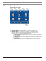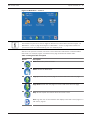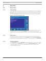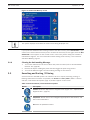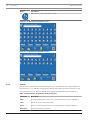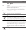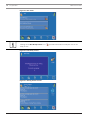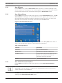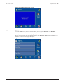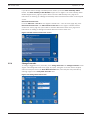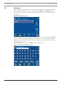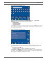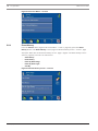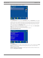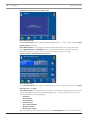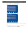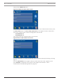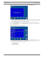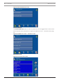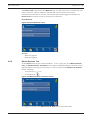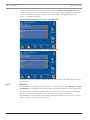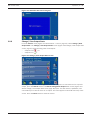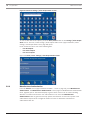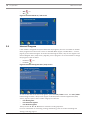
1
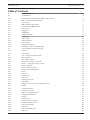
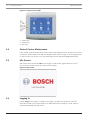
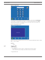
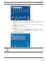
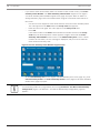
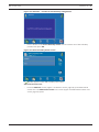
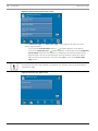
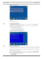
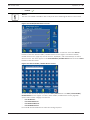
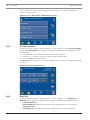
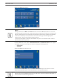
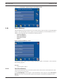
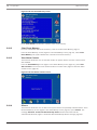
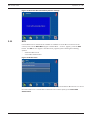
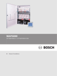
MAP Control Center
IUI-MAP0001-2
en User Manual
MAP Control Center
Table of Contents | en
3
Table of Contents
1
System Overview
5
1.1
Certifications
5
1.2
Environmental Conditions for MAP Control Center
5
1.3
MAP Control Center Description
5
1.3.1
LCD Screen
5
1.3.2
MAP Control Center LEDs
5
1.4
Control Center Maintenance
6
1.5
Idle Screen
6
1.6
Logging In
6
1.7
Logging Off
7
1.8
Screen Elements
8
2
Operation
10
2.1
Alarm Tasks
10
2.1.1
Silence Alarms
10
2.1.2
Clear Alarms
10
2.1.3
View Event Memory
10
2.1.4
Clearing An Anti-masking Message
11
2.2
Searching and Sorting / Filtering
11
2.2.1
Search
12
2.2.2
Sort / Filter
13
2.3
Arm - Using the Control Center
13
2.3.1
Arm All Areas
15
2.3.2
Arm Selected Areas
15
2.3.3
Arm Control Panel (Local) Area
15
2.4
Disarm – Using the Control Center
16
2.4.1
Disarm All Areas
16
2.4.2
Disarm Selected Areas
16
2.4.3
Disarm Control Panel Area
17
2.5
Users
17
2.5.1
Add User
18
2.5.2
Delete User
28
2.5.3
Edit User
29
2.5.4
Change Passcode
31
2.6
Schedules
32
2.6.1
Arming an Area at a Pre-programmed Time
34
2.7
Status
34
2.7.1
View Area Status
34
2.7.2
View Device Status
37
2.7.3
Bypass / Unbypass Device
41
2.7.4
Unbypass All Devices
42
2.8
Service
43
2.8.1
Event History
44
2.8.2
View Version Information
48
2.8.3
Enable / Disable Device
48
2.8.4
Set Time and Date
50
2.8.5
Walk Test
50
2.8.6
Motion Detector Test
55
2.8.7
Bell Test
56
Bosch Sicherheitssysteme, GmbH
User Manual
2014.11 | 06 | F.01U.168.328
4
en | Table of Contents
MAP Control Center
2.8.8
Change / View Output State
57
2.8.9
Manufacturer Authorization
58
2.8.10
Adjust Volume / Brightness
59
2.8.11
Chime Mode On / Off
59
2.9
Internal Program
60
2.10
Event Memory
61
2.10.1
View Event Memory
61
2.10.2
Clear Event Memory
62
2.10.3
View Alarm Counter
62
2.10.4
Silence
62
2.11
RPS
63
2014.11 | 06 | F.01U.168.328
User Manual
Bosch Sicherheitssysteme, GmbH
MAP Control Center
System Overview | en
1
System Overview
1.1
Certifications
5
The control center is designed to comply with the following certifications and standards:
1.2
1.3
Region
Certification
GERMANY
VdS
Class C, VdS G 111040
Europe
CE
Conformité Européene
EN50131-1/3 grade 3
Alarm Systems – Intrusion Systems
Environmental Conditions for MAP Control Center
Operating temperature:
-10 ºC to +55 ºC
Relative humidity:
5% to 95%
Type in accordance with EN 50131:
Type B
Environmental class II:
EN 50131, VdS 2110
Use:
Designed for indoor use
MAP Control Center Description
The MAP control center is an input device for the Modular Alarm Platform 5000 system. Each
control center has a vibrant-color 14 cm (5.7 in.) LCD screen. The durable touch screen
provides access to the various system functions through an interface with intuitive buttons.
Users touch the images directly on the screen to arm, disarm, or select other menu options.
The display text is shown in the language set by the user.
1.3.1
LCD Screen
To operate the MAP control center, apply moderate pressure to the keys and buttons shown
on the screen. To avoid damage to the touch-sensitive foil do not use sharp objects.
1.3.2
MAP Control Center LEDs
Three light-emitting diodes (LEDs) are located on the left edge of the MAP control center (
Figure 1.1 Control Center LEDs, page 6):
–
Green LED: Indicates that the control center is communicating with the control panel.
–
Yellow LED: Indicates that there is a trouble condition, that sensors are covered, or that
devices in the system are switched off or disabled.
–
Red LED: The default behavior indicates that an alarm condition exists in the security
system
Bosch Sicherheitssysteme, GmbH
User Manual
2014.11 | 06 | F.01U.168.328
6
en | System Overview
MAP Control Center
Figure 1.1 Control Center LEDs
1 – Green LED
2 – Yellow LED
3 – Red LED
1.4
Control Center Maintenance
If the control center housing is dirty, clean it with a soft dampened cloth. Do not use corrosive
or abrasive cleaners. Make sure that no fluid gets inside of the housing. To remove fingerprints
or dust from the LCD screen, use a soft cloth that you have dampened slightly with water.
1.5
Idle Screen
The control center shows the Idle screen (Figure 1.2 Idle screen, page 6) when it is not in
use. To use the system, touch the control center display.
Figure 1.2 Idle screen
1.6
Logging In
Use the Login screen (Figure 1.3 Login screen, page 7) to enter your passcode. The user
passcode is made up of a three-digit user ID (004–999) and a six-digit user code, which is
entered immediately after the user ID.
2014.11 | 06 | F.01U.168.328
User Manual
Bosch Sicherheitssysteme, GmbH
MAP Control Center
System Overview | en
7
Figure 1.3 Login screen
If the system does not recognize the passcode, the control center shows the Invalid Login
screen (Figure 1.4 Invalid Login screen, page 7). To empty the passcode field, press Clear
(the pencil eraser button). If an invalid passcode is entered ten1 times in succession, the
control center is locked for two minutes1.
Figure 1.4 Invalid Login screen
After the user enters a valid passcode, the touch screen shows the Main Menu (Figure 1.5 Main
Menu – screen 1, page 8 ).
See also
–
1.7
, page 9
Logging Off
A user is logged off
–
By pressing the exit button (Table 1.1 Navigation Bar description, page 9)
–
If there has been no user activity on the control center for two minutes1
1
Programmable value
Bosch Sicherheitssysteme, GmbH
User Manual
2014.11 | 06 | F.01U.168.328
8
1.8
en | System Overview
MAP Control Center
Screen Elements
Figure 1.5 Main Menu – screen 1
1.
Screen name: identifies the active screen.
2.
Menu buttons: Press a menu button to perform a task.
3.
Installer Mode Icon: Indicates that the control panel is in installer mode.
4.
RPS Connected Icon: Indicates that RPS is connected to the control panel.
5.
Information button: If it is flashing, press this button to view additional system
information and to clear the events, alarms or troubles. For more Event Memory
information, refer to Section View Event Memory, page 10.
–
If the Information button is flashing red, there are system events and alarms that the
user has not cleared.
–
If the Information button is flashing yellow, there are system troubles which the user
has not cleared.
–
6.
If the Information button is green, no additional system information is available.
Navigation bar: Press the buttons in the navigation bar to find tasks or to view system
information. Refer to Table 1.1 Navigation Bar description, page 9. Buttons in the
navigation bar that appear without their normal colors are not activated.
2014.11 | 06 | F.01U.168.328
User Manual
Bosch Sicherheitssysteme, GmbH
MAP Control Center
System Overview | en
9
Figure 1.6 Main Menu – screen 2
Notice!
The buttons on your touch screen might be different from the buttons shown in Figure 1.5
Main Menu – screen 1, page 8 and Figure 1.6 Main Menu – screen 2, page 9.The buttons on
your touch screen are determined by your user authority level.
After the user presses a button, the touch screen shows the task buttons contained within
that folder. For example, Figure 2.45 Status menu, page 34 shows the Status tasks.
Table 1.1 Navigation Bar description
Button
Description
Back: Shows the previous screen.
Home: Shows the Main Menu.
Page up: Shows the previous page on screens with more than one page.
Page down: Shows the next page on screens with more than one page.
Help: Shows helpful information about the active screen.
Exit: Logs the user off and switches the display to the idle screen (Figure 1.2
Idle screen, page 6).
Bosch Sicherheitssysteme, GmbH
User Manual
2014.11 | 06 | F.01U.168.328
10
en | Operation
MAP Control Center
2
Operation
2.1
Alarm Tasks
2.1.1
Silence Alarms
If the system generates an alarm, press the touch screen and enter your passcode (Figure 1.3
Login screen, page 7). If the system accepts your user passcode, the touch screen shows the
first alarm, e.g. an external intrusion alarm (Figure 2.1 External Intrusion Alarm screen, page
10) and the latest alarm. Any trouble events in the system are not shown on this display.
Figure 2.1 External Intrusion Alarm screen
To silence the alarm, press Silence. If the system recorded more than one alarm, the screen
shows the first and last alarms. Press View More to see all current events in the event
memory. For more information about event memory, refer to Section View Event Memory, page
10.
2.1.2
Clear Alarms
After silencing an alarm, the user must clear the alarm. From the alarm screen (Figure 2.1
External Intrusion Alarm screen, page 10), press View More to open the View Event Memory
screen (Figure 2.2 View Event Memory screen, page 11). To clear the alarm, press Clear Events
.
2.1.3
View Event Memory
If the Information button on the Main Menu (Figure 1.5 Main Menu – screen 1, page 8) flashes
red or yellow, press the Information button to view the View Event Memory screen (Figure
2.2 View Event Memory screen, page 11). For additional event memory options, refer to
Section Event Memory, page 61.
2014.11 | 06 | F.01U.168.328
User Manual
Bosch Sicherheitssysteme, GmbH
MAP Control Center
Operation | en
11
Figure 2.2 View Event Memory screen
Notice!
The system displays events with the newest event being displayed first.
If your passcode authorizes the clearing of alarms and other events, press Clear Events. If you
cannot clear certain events because you do not have the necessary access rights, then the Not
Authorized screen appears on the control center. In this case, please notify your installer or
maintenance engineer. For more information about viewing event memory, refer to Section
View Event Memory, page 10.
2.1.4
Clearing An Anti-masking Message
1.
Turn on the walk test for the area in which the point is located (refer to Section Motion
Detector Test, page 55).
2.2
2.
Remove the object masking the point and then trigger the point using motion.
3.
Turn off the walk test again. The anti-masking message is now cleared.
Searching and Sorting / Filtering
Some functions in the MAP system user interface call for or require searching, sorting, or
filtering. Where these functions are possible, the Search and Sort / Filter (Table 2.1 Search
and Sort / Filter button descriptions, page 11) buttons appear on the screen.
Table 2.1 Search and Sort / Filter button descriptions
Button
Description
Search: Shows the Alphanumeric Keypad screen (Figure 2.3 1. Alphanumeric
Keypad screen 1, page 12).
Sort/Filter: Shows a list of sort categories appropriate to the function, and
the A-Z and Z-A buttons.
A-Z: Sorts in alphabetical order.
Bosch Sicherheitssysteme, GmbH
User Manual
2014.11 | 06 | F.01U.168.328
12
en | Operation
MAP Control Center
Button
Description
Z-A: Sorts in reverse alphabetical order.
Figure 2.3 1. Alphanumeric Keypad screen 1
Figure 2.4 2. Alphanumeric Keypad screen 2
2.2.1
Search
Search uses an alphanumeric keypad display for input. The alphanumeric keypad display has
the numerals 0 - 9, a QWERTY arrangement of letters with additional special characters, and
five commands (refer to Table 2.2 Alphanumeric Keypad Command descriptions, page 12).
Table 2.2 Alphanumeric Keypad Command descriptions
Command
Description
Shift
Creates capital letters. Press once. The next letter pressed is capitalized.
Clear
Clears all input in the Search field.
Space
Inserts a space (same function as the spacebar on a manual keyboard).
Backspace
Clears the previous character.
2014.11 | 06 | F.01U.168.328
User Manual
Bosch Sicherheitssysteme, GmbH
MAP Control Center
2.2.2
Operation | en
Command
Description
Enter
Starts the search process.
13
Sort / Filter
When you use the Sort / Filter function, the sorting can be alphabetical (from A - Z or from Z
to A) for all devices or all areas, for example, or the function can be narrowed by selecting
faulted, bypassed, unbypassed, enabled, or disabled devices.
All areas can be sorted, or the sorting function can be narrowed by selecting armed, disarmed,
ready to arm, not ready to arm, ready to disarm, or not ready to disarm areas. More
information is provided in the sections that cover the commands that allow sorting and
filtering.
2.3
Arm - Using the Control Center
Notice!
A system installed with Smartkey or Blocklock controls can only be armed or disarmed by
those controls. It cannot be armed or disarmed using a control center.
The Arm menu allows the user to arm all areas, arm selected areas, or arm the control panel
area.
Notice!
For the system default, the area containing the control center is the local area. During
installation, each control center can be assigned to a specific area making that area the local
area for that control center. Therefore, the displayed button name on each control center is
unique for each installation. Depending on how your system is configured, you might need to
arm the control panel area first.
On the Main Menu (Figure 1.5 Main Menu – screen 1, page 8), press Arm, then select an
arming option from the on-screen buttons (Arm All Areas, Arm Selected Areas, or Arm Control
Panel Area) on the Arm Menu (Figure 2.5 Arm menu, page 14). Selecting an area that is Ready
to Arm initiates the arming sequence and displays the Exit Delay screen (Figure 2.6 Exit Delay
screen, page 14) which indicates how much time you have to evacuate the arming area(s)
before your presence sets off an alarm. Selecting an area that is Not Ready to Arm displays an
Arming Failure screen (Figure 2.7 Arming Failure screen, page 14) which indicates which
area(s) can be force armed [armed by forcing bypass (refer to Section Bypass / Unbypass
Device, page 41) of all points that are not ready to be armed] and which areas cannot be
force armed.
Notice!
Force arming is not available when a related area must be armed first, when too many points
are already bypassed, or when an area contains specific unbypassable points.
Bosch Sicherheitssysteme, GmbH
User Manual
2014.11 | 06 | F.01U.168.328
14
en | Operation
MAP Control Center
Figure 2.5 Arm menu
Notice!
Clicking on the Not Ready to Arm icon (
) provides information on why the area is not
ready to arm.
Figure 2.6 Exit Delay screen
Figure 2.7 Arming Failure screen
2014.11 | 06 | F.01U.168.328
User Manual
Bosch Sicherheitssysteme, GmbH
MAP Control Center
2.3.1
Operation | en
15
Arm All Areas
From the Arm menu, press the Arm All Areas button. As above, if all areas are Ready to Arm,
the Exit Delay screen is displayed; if not, the Arming Failure screen opens with the lock button
in the locked position and the armed status showing on the Arm All Areas button.
2.3.2
Arm Selected Areas
From the Arm menu (Figure 2.5 Arm menu, page 14), press the Arm All Areas button. The Arm
Selected Areas screen (Figure 2.8 Arm Selected Areas screen, page 15) opens. The text and
the lock button show status information on the button for each area. To arm an area, press
the button for an area that is not already armed; then press the Arm button.
Figure 2.8 Arm Selected Areas screen
To sort the list of areas before selecting some to arm, press the Sort / Filter button. Refer to
Table 2.3 Arming indicators, page 15 for the possible arming indicators.
Table 2.3 Arming indicators
Indicator
Description
Disarmed
Area currently disarmed
Ready to Arm
All points in the area are ready to arm
Not Ready to Arm
Some points in the area are faulted and not
ready to arm; all points must either be
returned to normal or bypassed.
Armed
2.3.3
Area currently armed
Arm Control Panel (Local) Area
From the Arm menu (Figure 2.5 Arm menu, page 14), press the Arm Control Panel Area
button.
Notice!
Depending on how your system is configured, the displayed button name on each control
center is unique for each installation.
The Arm menu opens with the lock button in the locked position and the area’s armed status
showing on the Arm Control Panel Area button.
Bosch Sicherheitssysteme, GmbH
User Manual
2014.11 | 06 | F.01U.168.328
16
en | Operation
2.4
MAP Control Center
Disarm – Using the Control Center
The Disarm menu allows the user to disarm all areas, disarm selected areas, or disarm the
entire control panel (or installation-specific local) area. On the Main Menu (Figure 1.5 Main
Menu – screen 1, page 8), press Disarm, then select a disarming option from the on-screen
buttons on the Disarm menu (Figure 2.9 Disarm menu, page 16).
Figure 2.9 Disarm menu
2.4.1
Disarm All Areas
From the Disarm menu (Figure 2.9 Disarm menu, page 16), press the Disarm All Areas
button. The control center display shows the message: Attention - All authorized areas are
disarmed (Figure 2.10 Attention message: All authorized areas are disarmed, page 16). Then the
Disarm menu opens with the lock button in the unlocked position and the disarmed status
showing on the Disarm All Areas button.
Figure 2.10 Attention message: All authorized areas are disarmed
2.4.2
Disarm Selected Areas
From the Disarm menu, press the Disarm Selected Areas button. The Disarm Selected Areas
screen (Figure 2.11 Disarm Selected Areas screen, page 17) opens. The text and the lock
button show status information on the button for each area. To disarm an area, press the
button for an area that is not already disarmed; then press the Disarm button. To sort the list
of areas before selecting some to disarm, press the Sort/Filter button.
2014.11 | 06 | F.01U.168.328
User Manual
Bosch Sicherheitssysteme, GmbH
MAP Control Center
Operation | en
17
Figure 2.11 Disarm Selected Areas screen
2.4.3
Disarm Control Panel Area
From the Disarm menu (Figure 2.9 Disarm menu, page 16), press the Disarm Control Panel
Area button. Usually, this button is the area where the control center is located, but it could
be any area designated as the local area. The button name is unique at each installation.
To disarm the control panel area, press the Control Panel Area button then press the Disarm
button. The lock icon on the Control Panel Area button changes to the unlocked position and
the area's disarmed status shows on the button.
2.5
Users
Notice!
The options to perform user-related operations are restricted by permission set / access
profile.
The Users menu allows the user to add (up to the maximum number of users allowed), delete
or edit a user’s profile or to change a user’s passcode. On the Main Menu (Figure 1.5 Main
Menu – screen 1, page 8) press Users, then select the user category from the on-screen
buttons (Figure 2.12 Users menu, page 17).
Figure 2.12 Users menu
Bosch Sicherheitssysteme, GmbH
User Manual
2014.11 | 06 | F.01U.168.328
18
en | Operation
MAP Control Center
See also
–
2.5.1
Users, page 17
Add User
Notice!
A Smartkey user must also be entered as a control center user. Refer to Section Add Smartkey
User, page 21.
A control center user is not required to be a Smartkey user. Refer to Section Add Control
Center User, page 23.
–
From the Users menu (Figure 2.12 Users menu, page 17), press Add User. The Add User
screen (Figure 2.13 Add User screen, page 18) opens
Figure 2.13 Add User screen
Enter User ID
–
From the Add User screen (Figure 2.13 Add User screen, page 18), press Enter User ID.
The Enter User ID screen (Figure 2.14 Enter User ID screen, page 18) opens.
Figure 2.14 Enter User ID screen
–
Press Enter User ID to enter a specific three-digit user ID, or press Request Next
Available User ID to have the system assign a user ID. When you select Enter User ID,
the Enter User ID telephone keypad display screen (Figure 2.15 Enter User ID Keypad
screen, page 19) opens.
2014.11 | 06 | F.01U.168.328
User Manual
Bosch Sicherheitssysteme, GmbH
MAP Control Center
Operation | en
–
19
Press the numbered buttons on the keypad screen. Each number appears in the
Enter new user ID field. Press Clear to make corrections.
–
Press OK to enter the specific user ID.
Figure 2.15 Enter User ID Keypad screen
–
The assigned user ID appears in lighter text under the button name on a confirmation
screen (Figure 2.16 User ID Control Center Confirmation screen, page 19). Press OK to
complete the entry.
Figure 2.16 User ID Control Center Confirmation screen
Enter User Name
–
From the Add User screen (Figure 2.13 Add User screen, page 18), press Enter User Name
. The Enter User Name screen (Figure 2.17 Enter User Name screen, page 20) opens.
Bosch Sicherheitssysteme, GmbH
User Manual
2014.11 | 06 | F.01U.168.328
20
en | Operation
MAP Control Center
Figure 2.17 Enter User Name screen
–
On the Enter User Name screen, press Enter User First Name. The alphanumeric keypad
screen (Figure 2.18 1. Enter User Name - Alphanumeric keypad screen 1, page 20) opens.
Also refer to Figure 2.19 2. Enter User Name - Alphanumeric keypad screen 2, page 21
–
Use the alphanumeric buttons to enter the user’s first name. Refer to Table 2.3 Arming
indicators, page 15 for information about using the commands at the bottom of the
screen.
–
Press Enter to complete the entry. The user’s first name appears in lighter text under the
Enter User First Name button name.
Figure 2.18 1. Enter User Name - Alphanumeric keypad screen 1
2014.11 | 06 | F.01U.168.328
User Manual
Bosch Sicherheitssysteme, GmbH
MAP Control Center
Operation | en
21
Figure 2.19 2. Enter User Name - Alphanumeric keypad screen 2
–
On the Enter User Name screen, press Enter User Last Name.
–
On the alphanumeric keypad screen, enter the user’s last name. Refer to Table 2.3 Arming
indicators, page 15 for information about using the commands at the bottom of the
screen.
–
Press Enter to complete the entry. The user’s last name appears in lighter text under the
Enter User Last Name button name.
–
Press Enter to complete the User Name entry.
Add Smartkey User
–
To designate a Smartkey user, press Add Smartkey User on the Add User screen (Figure
2.13 Add User screen, page 18). The Add Smartkey User screen (Figure 2.20 Add Smartkey
User screen, page 21) opens.
Figure 2.20 Add Smartkey User screen
Notice!
The next three steps are optional in the Add User procedure.
Bosch Sicherheitssysteme, GmbH
User Manual
2014.11 | 06 | F.01U.168.328
22
en | Operation
MAP Control Center
–
If you wish to enter the Smartkey token’s ID number at the control center, press Enter
Smartkey Token Number. The Enter Smartkey Token Number keypad screen (Figure
2.21 Enter Smartkey Token Number keypad screen, page 22) opens. Refer to Table 2.3
Arming indicators, page 15 for information about using the commands at the bottom of
the screen.
–
Use the on-screen keypad to enter the 8-character ID found on the Smartkey token.
The code appears in the Enter field and a Verify Code field appears.
–
Enter the same code again. The code appears in the Verify Code field.
–
Press OK.
If the token number in the Enter field matches the number entered in the Verify
Code field, the Smartkey token number appears in lighter text under the Enter
Smartkey Token Number button name on the Add Smartkey User screen. If these
numbers do not match, an error message is displayed, and you must re-enter the
token number and verify code.
Figure 2.21 Enter Smartkey Token Number keypad screen
–
On the Add Smartkey User screen (Figure 2.20 Add Smartkey User screen, page 21), press
Select Smartkey Profile. The Select Smartkey Profile screen (Figure 2.23 Select Smartkey
Profile screen, page 23) opens.
Notice!
If no Smartkey profiles are programmed, the message Attention - Use RPS to Add Smartkey
Configuration (Figure 2.22 Attention – Use RPS to Add Smartkey Configuration, page 23)
appears.
2014.11 | 06 | F.01U.168.328
User Manual
Bosch Sicherheitssysteme, GmbH
MAP Control Center
Operation | en
23
Figure 2.22 Attention – Use RPS to Add Smartkey Configuration
–
Press a button on the Select Smartkey Profile screen to select one of the Smartkey
profiles; then press OK.
Figure 2.23 Select Smartkey Profile screen
A symbol appears on the Add Smartkey User button.
Add Control Center User
–
From the Add User screen (Figure 2.13 Add User screen, page 18), press Add Control
Center User. The Add Control Center User screen (Figure 2.24 Add Control Center User
screen, page 24) opens.
Bosch Sicherheitssysteme, GmbH
User Manual
2014.11 | 06 | F.01U.168.328
24
en | Operation
MAP Control Center
Figure 2.24 Add Control Center User screen
–
Press Select User Type. The Select User Type screen (Figure 2.25 Select User Type
screen, page 24) opens.
–
If you press the Standard User button, a (
–
If you press Temporary User, a ) symbol appears on the button.
symbol appears on the button and the Temporary
User Duration keypad screen (Figure 2.26 Temporary User Duration keypad screen,
page 25) opens. Use the screen keypad to enter the number of days (0 to 99) to
allow access for the temporary user; then press OK to return to the Select User
Type screen.
Notice!
A temporary user with 0 days validity is an inactive user. Inactive users can be activated by
using RPS for MAP.
Figure 2.25 Select User Type screen
2014.11 | 06 | F.01U.168.328
User Manual
Bosch Sicherheitssysteme, GmbH
MAP Control Center
Operation | en
25
Figure 2.26 Temporary User Duration keypad screen
–
Press OK. The selected user type appears in lighter text under the Select User Type
button name on the Add Control Center User screen.
–
From the Add Control Center User (Figure 2.24 Add Control Center User screen, page 24)
screen, Select User Profile. The Select User Profile screen (Figure 2.27 Select User
Profile screen, page 25) opens.
Figure 2.27 Select User Profile screen
–
From the Select User Profile screen (Figure 2.27 Select User Profile screen, page 25)
select a user profile. A symbol appears on the selected button (Figure 2.28 User Profile
Selection: Standard User, page 26).
Bosch Sicherheitssysteme, GmbH
User Manual
2014.11 | 06 | F.01U.168.328
26
en | Operation
MAP Control Center
Figure 2.28 User Profile Selection: Standard User
–
Press OK. The selected user profile appears in lighter text under the Select User Profile
button name.
–
From the Add Control Center User (Figure 2.24 Add Control Center User screen, page 24)
screen, Select User Language. The Select User Language screen (Figure 2.29 Select User
Language, page 26) opens.
–
From the Select User Language screens (1 or 2), select German, English, French or
Dutch. A symbol appears on the selected button.
Figure 2.29 Select User Language
–
Press the OK button. The selected language appears in lighter text under the Select User
Language button name.
–
From the Add Control Center User screen, Select Exit Delay. The Select Exit Delay
screen (Figure 2.30 Select Exit Delay screen, page 27) opens.
–
From the Select Exit Delay screen, select Standard or Extended. A symbol appears on the selected button (Figure 2.30 Select Exit Delay screen, page
27).
2014.11 | 06 | F.01U.168.328
User Manual
Bosch Sicherheitssysteme, GmbH
MAP Control Center
Operation | en
27
Figure 2.30 Select Exit Delay screen
–
Press the OK button. The selected exit delay type appears in lighter text under the Select
Exit Delay button name.
–
When all buttons on the Add Control Center User screen (Figure 2.24 Add Control Center
User screen, page 24) show an entry in lighter text, press OK. The Add User screen opens.
Completing Add User
–
When the entries are completed on the Add User screen (Figure 2.31 Completed Add User
screen, page 27), entries in lighter text should appear under the Enter User ID and Enter
User Name buttons. A symbol should appear on either the Add Smartkey User or Add Control Center
User button.
Notice!
Until all of the above steps are completed, the Add User button will be in lighter text.
Figure 2.31 Completed Add User screen
–
Press the Add User button. The screen briefly shows the message Attention - Request
to: Add User Succeeded (Figure 2.32 Attention: Add User Succeeded, page 28). Then the
Users menu appears.
Bosch Sicherheitssysteme, GmbH
User Manual
2014.11 | 06 | F.01U.168.328
28
en | Operation
MAP Control Center
Figure 2.32 Attention: Add User Succeeded
2.5.2
Delete User
From the Users menu (Figure 2.12 Users menu, page 17), press the Delete User button. The
Delete User screen (Figure 2.33 Delete User screen, page 28) opens. If necessary, press the
Search or Sort / Filter button to find the user. Refer to Section 2.2 Searching and Sorting /
Filtering, page 11.
Figure 2.33 Delete User screen
From the Delete User screen, press one of the menu buttons containing a user's name. A
message appears asking for confirmation (Figure 2.34 Confirm Delete User screen, page 29).
To proceed, press the Confirm Delete button. If you do not want to delete that user, press the
Back button.
2014.11 | 06 | F.01U.168.328
User Manual
Bosch Sicherheitssysteme, GmbH
MAP Control Center
Operation | en
29
Figure 2.34 Confirm Delete User screen
2.5.3
Edit User
From the Users menu (Figure 2.12 Users menu, page 17), press Edit User. The Edit User
screen (Figure 2.35 Edit User screen, page 29) opens with a list of users. Find the user you
wish to edit and press the corresponding button. The Edit User - User ID screen (Figure 2.36
Edit User – User ID screen, page 30) opens.
Figure 2.35 Edit User screen
Bosch Sicherheitssysteme, GmbH
User Manual
2014.11 | 06 | F.01U.168.328
30
en | Operation
MAP Control Center
Figure 2.36 Edit User – User ID screen
From the Edit User - User ID screen, you can reset the passcode, edit the user name, edit a
Smartkey user, and edit a control center user.
Reset Passcode
From the Edit User - User ID screen (Figure 2.36 Edit User – User ID screen, page 30), press
Reset Passcode. A list of users appears. Press the button for the user whose passcode you
wish to reset. A message appears indicating that the request to reset the passcode
succeeded.
Edit User Name
From the Edit User - User ID screen (Figure 2.36 Edit User – User ID screen, page 30), press
Edit User Name. The Enter User Name screen (Figure 2.17, Page 19) opens. Press either
Enter User First Name or Enter User Last Name. The alphanumeric keypad display screen
(Figure 2.18, Page 20) opens with the name showing in the Enter User Name field. Use the
editing buttons at the bottom of the screen and the alphanumeric keys to make the desired
changes. Press the Enter button to return to the Enter User Name screen. Press the OK
button to return to the Edit User - User ID screen.
Edit Smartkey User
From the Edit User - User ID screen (Figure 2.36 Edit User – User ID screen, page 30), press
Edit Smartkey User. The Edit Smartkey User screen (Figure 2.37 Edit Smartkey User screen,
page 30) opens.
Figure 2.37 Edit Smartkey User screen
2014.11 | 06 | F.01U.168.328
User Manual
Bosch Sicherheitssysteme, GmbH
MAP Control Center
Operation | en
31
If you wish to add or change a Smartkey token number, press the Enter Smartkey Token
button. The Enter Smartkey Token Number keypad screen (Figure 2.21 Enter Smartkey Token
Number keypad screen, page 22) opens. Refer to Section Add Smartkey User, page 21 for
instructions on entering (or editing) the Smartkey token's hexadecimal number on the keypad
screen.
Edit Control Center User
From the Edit User - User ID screen (Figure 2.36 Edit User – User ID screen, page 30), press
Edit Control Center User. The Edit Control Center User screen (Figure 2.38 Edit Control
Center User screen, page 31) opens. Refer to Section Add Control Center User, page 23 for
instructions on adding or editing information about the control center user.
Figure 2.38 Edit Control Center User screen
2.5.4
Change Passcode
To change a logged-in user’s passcode, press Change Passcode. The Change Passcode screen
(Figure 2.39 Change Passcode screen, page 31) opens. Using the on-screen numeric keypad,
enter the new passcode in the Enter New Passcode field, then verify the new passcode by
entering it again in the Verify New Passcode field.
Figure 2.39 Change Passcode screen
Bosch Sicherheitssysteme, GmbH
User Manual
2014.11 | 06 | F.01U.168.328
32
2.6
en | Operation
MAP Control Center
Schedules
The Schedules screen allows the user to view or edit a programmed schedule. On the Main
Menu (Figure 1.5 Main Menu – screen 1, page 8), press Schedules. The Schedules screen (
Figure 2.40 Schedules screen, page 32) opens with a list of the schedules programmed into
the system.
Figure 2.40 Schedules screen
To find a schedule to view or change, the user can search or sort the list. Press the Search
button to show the alphanumeric keypad screen (Figure 2.41 1. Search Schedules screen 1,
page 32). Use the numeric, alphabetic, and command keys to enter the name of a schedule.
The name appears in the
Search Schedules field. Press the Enter button to start the search.
Figure 2.41 1. Search Schedules screen 1
2014.11 | 06 | F.01U.168.328
User Manual
Bosch Sicherheitssysteme, GmbH
MAP Control Center
Operation | en
33
Figure 2.42 2. Search Schedules screen 2
To sort or filter the list of schedules, press the Sort / Filter button. The Sort / Filter
Schedules screen opens. Select a filter category from the list:
–
List All Schedules
–
List Inactive Schedules
–
List Active Schedules
Press the A - Z or Z - A button to select the sorting sequence. Press the OK button to start the
sorting. For more information on searching, sorting, and filtering, refer to Section Searching
and Sorting / Filtering, page 11.
Figure 2.43 Sort/Filter Schedules screen
To view or edit a schedule, press the schedule’s button. The Change Schedule screen (Figure
2.44 Change Schedule screen, page 34) opens. By pressing the schedule’s button, the user
can:
–
Disable the schedule ( –
Enable the schedule ( ), or
) (Figure 2.40 Schedules screen, page 32).
Using the Hours and Minutes buttons and the + and - buttons, the user can edit the time of
the schedule. Press the OK button to accept the changes. A message appears briefly stating
that the request to change the schedule has succeeded.
Bosch Sicherheitssysteme, GmbH
User Manual
2014.11 | 06 | F.01U.168.328
34
en | Operation
MAP Control Center
Figure 2.44 Change Schedule screen
See also
2.6.1
–
Schedules, page 33
–
Schedules, page 33
Arming an Area at a Pre-programmed Time
If the system has been programmed to arm an area at a specific time, the keypad emits an
interval tone when the alarm is activated and the Exit Delay screen (Figure 2.6 Exit Delay
screen, page 14) is shown. The Exit Delay screen indicates how much time you have to exit the
area before your presence triggers an alarm.
2.7
Status
The Status menu provides access to functions for viewing the system status. From the Main
Menu (Figure 1.5 Main Menu – screen 1, page 8), press Status, then select the status category
from the on-screen buttons (Figure 2.45 Status menu, page 34).
Figure 2.45 Status menu
2.7.1
View Area Status
From the Status menu (Figure 2.45 Status menu, page 34), press View Area Status. The View
Area Status screen (Figure 2.46 View Area Status screen, page 35) opens.
2014.11 | 06 | F.01U.168.328
User Manual
Bosch Sicherheitssysteme, GmbH
MAP Control Center
Operation | en
35
Figure 2.46 View Area Status screen
The + symbol is displayed when an area is Not Ready to Arm or Not Ready to Disarm, or when
an area is Ready to Arm but can only be armed by a Smartkey or Blocklock. Pressing a
displayed + symbol opens a View Area Status Detail screen (Figure 2.47 View Area Status Detail
screen, page 35).
Figure 2.47 View Area Status Detail screen
To find an area to view, the user can search or sort the list on the View Area Status screen (
Figure 2.46 View Area Status screen, page 35). Press the Search button to show the
alphanumeric keypad screen (Figure 2.48 1. Search View Area Status screen 1, page 36). Use
the numeric, alphabetic, and command keys to enter an area's name. The name appears in the
Search View Area Status field. Press the Enter button to start the search.
Bosch Sicherheitssysteme, GmbH
User Manual
2014.11 | 06 | F.01U.168.328
36
en | Operation
MAP Control Center
Figure 2.48 1. Search View Area Status screen 1
Figure 2.49 2. Search View Area Status screen 2
To sort or filter the list of areas, press the Sort / Filter button. The Sort / Filter: View Area
Status screen (Figure 2.50 1. Sort/Filter View Area Status screen 1, page 37, see alsoFigure
2.51 2. Sort/Filter View Area Status screen 2, page 37) opens. Select a filter category from the
list:
–
List All Areas
–
List Armed Areas
–
List Disarmed Areas
–
List Ready To Arm Areas
–
List Not Ready To Arm Areas
–
List Ready To Disarm Areas
–
List Not Ready To Disarm Areas
Press the A - Z or Z - A button to select the sorting sequence.
For more information on searching, sorting, and filtering, refer to Section Searching and
Sorting / Filtering, page 11.
2014.11 | 06 | F.01U.168.328
User Manual
Bosch Sicherheitssysteme, GmbH
MAP Control Center
Operation | en
37
Figure 2.50 1. Sort/Filter View Area Status screen 1
Figure 2.51 2. Sort/Filter View Area Status screen 2
See also
–
2.7.2
View Area Status, page 36
View Device Status
From the Status menu (Figure 2.45 Status menu, page 34), press View Device Status. The
Device Status Select screen (Figure 2.52 Device Status Select screen, page 38) opens.
Bosch Sicherheitssysteme, GmbH
User Manual
2014.11 | 06 | F.01U.168.328
38
en | Operation
MAP Control Center
Figure 2.52 Device Status Select screen
From the Device Status Select screen, press Select Area or All Devices.
–
If Select Area is pressed, the Select Area screen (Figure 2.53 Select Area screen, page 38
) opens. Press the button for an area. The View Device Status screen (Figure 2.54 View
Device Status screen, page 39) opens with a list of the devices in the selected area.
Figure 2.53 Select Area screen
–
If All Devices is pressed, the View Device Status screen (Figure 2.54 View Device Status
screen, page 39) opens with a list of all devices. The device status shows in lighter text
under the device name.
2014.11 | 06 | F.01U.168.328
User Manual
Bosch Sicherheitssysteme, GmbH
MAP Control Center
Operation | en
39
Figure 2.54 View Device Status screen
To find a device to view, the user can search or sort the list. Press the Search button to show
the Search View Device Status screen (Figure 2.55 Search View Device Status screen 1, page
39). Use the numeric, alphabetic, and command keys to enter a device's name. The name
appears in the Search View Device Status field. Press the Enter button to start the search.
Figure 2.55 Search View Device Status screen 1
Figure 2.56 Search View Device Status screen 2
To sort or filter the list of devices, press the Sort / Filter button. The Sort / Filter: View
Device Status Screen (Figure 2.57 Sort / Filter View Device Status screen, page 40) opens.
Bosch Sicherheitssysteme, GmbH
User Manual
2014.11 | 06 | F.01U.168.328
40
en | Operation
MAP Control Center
Notice!
If the user comes to this menu through Select Area, then the following filter displays the
corresponding status for the devices in that area only.
Select a filter category from the list:
–
List All Devices
–
List Faulted Devices
–
List Bypassed Devices
–
List Unbypassed Devices
–
List Disabled Devices
–
List Enabled Devices
Then press the A - Z or Z - A button to select the sorting sequence.
For more information on searching, sorting, and filtering, refer to Section Searching and
Sorting / Filtering, page 11.
Figure 2.57 Sort / Filter View Device Status screen
Press one of the device buttons to view additional details of that device. A View Device Status
Detail screen (Figure 2.58 View Device Status Detail screen, page 40) opens showing the
details for the selected device.
Figure 2.58 View Device Status Detail screen
See also
–
2014.11 | 06 | F.01U.168.328
View Device Status, page 39
User Manual
Bosch Sicherheitssysteme, GmbH
MAP Control Center
2.7.3
Operation | en
41
Bypass / Unbypass Device
To arm the system, regardless of a particular device’s status, the user can bypass that device.
Notice!
A device cannot be bypassed if the area containing the device is armed, there is an active
event in the system from the area containing the device, or if the device is in Walk Test.
For example, if a window contact is installed on a window that the user wants to leave open,
the user can bypass that window contact point. This allows the user to arm the system even
though the window contact point’s status is Active.
Notice!
Bypassing a device only disables the device’s ability to notify the security system of an alarm
or trouble event. Tamper events are still active in a bypassed device.
From the Status menu (Figure 2.45 Status menu, page 34), press Bypass / Unbypass Device.
The Bypass / Unbypass Device screen (Figure 2.59 Bypass/Unbypass Device screen, page 41)
lists the devices and displays whether each device is either:
–
Bypassed (
–
Unbypassed ( ), or
).
Press a device’s on-screen button to change its bypass status.
Figure 2.59 Bypass/Unbypass Device screen
To find a specific device, the user can search or sort the list. Press the Search button to show
the Search Bypass / Unbypass Device screen (Figure 2.60 Search Bypass / Unbypass Device
screen, page 42). Use the numeric, alphabetic, and command keys to enter a device's name.
The name appears in the Search Bypass / Unbypass Device field. Press the Enter button to
start the search.
Bosch Sicherheitssysteme, GmbH
User Manual
2014.11 | 06 | F.01U.168.328
42
en | Operation
MAP Control Center
Figure 2.60 Search Bypass / Unbypass Device screen
To sort or filter the list of devices, press the Sort / Filter button. The Sort/Filter Bypass /
Unbypass Device screen (Figure 2.61 Sort/Filter Bypass/Unbypass Device screen, page 42)
opens. Select a filter category from the list:
–
List All Devices
–
List Faulted Devices
–
List Bypassed Devices
–
List Unbypassed Devices
Then press the A - Z or Z - A button to select the desired sorting sequence.
For more information on searching, sorting, and filtering, refer to Section 2.2 Searching and
Sorting / Filtering, page 11.
Figure 2.61 Sort/Filter Bypass/Unbypass Device screen
2.7.4
Unbypass All Devices
To unbypass all bypassed devices, press Unbypass All Devices on the Status menu (Figure
2.45 Status menu, page 34). The Attention - Request to: Unbypass All Devices Succeeded
screen (Figure 2.62 Unbypass All Devices Succeeded screen, page 43) opens, and all bypassed
devices return to their unbypassed state (Normal, Faulted, Missing, Trouble).
2014.11 | 06 | F.01U.168.328
User Manual
Bosch Sicherheitssysteme, GmbH
MAP Control Center
Operation | en
43
Figure 2.62 Unbypass All Devices Succeeded screen
2.8
Service
The Service menu provides access to system service functions. On the Main Menu (Figure 1.5
Main Menu – screen 1, page 8), press the Service button. The Service menu (Figure 2.63
Service Menu – screen 1, page 43, Figure 2.64 Service Menu – screen 2, page 43 and Figure
2.65 Service Menu – screen 3, page 44) opens.
Figure 2.63 Service Menu – screen 1
Figure 2.64 Service Menu – screen 2
Bosch Sicherheitssysteme, GmbH
User Manual
2014.11 | 06 | F.01U.168.328
44
en | Operation
MAP Control Center
Figure 2.65 Service Menu – screen 3
2.8.1
Event History
From the Service menu (Figure 2.63 Service Menu – screen 1, page 43), press the Event
History button. The Event History screen (Figure 2.66 Event History screen – screen 1, page
44) opens. Refer also to the Event History screen - page 2 (Figure 2.67 Event History screen –
screen 2, page 45). The user can select from:
–
View History
–
Print History
–
Filter By Date Range
–
Filter By Event Type
–
Sort By
Figure 2.66 Event History screen – screen 1
2014.11 | 06 | F.01U.168.328
User Manual
Bosch Sicherheitssysteme, GmbH
MAP Control Center
Operation | en
45
Figure 2.67 Event History screen – screen 2
View History
On the Event History screen, press the View History button. The View History screen (Figure
2.68 View History screen, page 45) opens with a list of the events stored in the control panel's
history memory. These events are not limited to events initiated by the system’s sensors. All
system activity, such as arming and disarming the system, system troubles, system tampers,
and so on are listed on the View History screen.
The default history filter is the last 24 hours. To expand the time range, select Filter by Date
Range (refer to Section Filter By Date Range, page 46).
To view only sensor events, refer to Section Event Memory, page 61.
Figure 2.68 View History screen
Print History
On the Event History screen (Figure 2.66 Event History screen – screen 1, page 44), press Print
History. The system prints the history data using the system printer. The control center
display shows the message:
Attention - Request to: Print History Succeeded (Figure 2.69 Print History Succeeded screen,
page 46) or The printer is not ready.
Bosch Sicherheitssysteme, GmbH
User Manual
2014.11 | 06 | F.01U.168.328
46
en | Operation
MAP Control Center
Figure 2.69 Print History Succeeded screen
Filter By Date Range
On the Event History screen (Figure 2.66 Event History screen – screen 1, page 44), press Filter
By Date Range. The Filter:
Event History Dates screen (Figure 2.70 Filter: Event History Dates screen, page 46) opens.
Press Beginning Date or Ending Date, then touch the date and time buttons to select the
element to change. Press the + and - buttons to change the dates in the range.
Figure 2.70 Filter: Event History Dates screen
Filter By Event Type
On the Event History screen (Figure 2.66 Event History screen – screen 1, page 44), press Filter
By Event Type. The Filter:
Event History Type screen opens (refer to Figure 2.71 Filter: Event History Type screen – screen
1, page 47andFigure 2.72 Filter: Event History Type screen – screen 2, page 47). The user can
select an option from the following list:
–
All Events
–
Alarm Events
–
Trouble Events
–
System Events
–
Arm / Disarm Events
–
Operation Events
–
Maintenance Events
After an option is pressed, the screen returns to the Event History screen. The selected event
2014.11 | 06 | F.01U.168.328
User Manual
Bosch Sicherheitssysteme, GmbH
MAP Control Center
Operation | en
47
type appears in lighter text on the Filter By Event Type button.
Figure 2.71 Filter: Event History Type screen – screen 1
Figure 2.72 Filter: Event History Type screen – screen 2
Sort By
On the Event History screen (Figure 2.67 Event History screen – screen 2, page 45), press Sort
By. The Sort By screen opens, showing two options:
–
ID
–
Event Type
Press one of the options to sort the events. The screen returns to the Event History screen,
with the Sort By choice listed in lighter text on the Sort By button.
Bosch Sicherheitssysteme, GmbH
User Manual
2014.11 | 06 | F.01U.168.328
48
en | Operation
MAP Control Center
Figure 2.73 Sort By screen
See also
–
2.8.2
Event History, page 48
View Version Information
On the Service menu (Figure 2.63 Service Menu – screen 1, page 43), select View Version
Information. The View Version Information screen (Figure 2.74 View Version Information
screen, page 48) opens and shows:
–
the control panel's firmware version,
–
the control panel's hardware version, and
–
the control center's firmware version.
Figure 2.74 View Version Information screen
2.8.3
Enable / Disable Device
Disabling a device effectively removes that device from the security system. The control panel
ignores all signals received from a disabled device. Only authorized users, such as installers or
security officers, can disable devices. For information on bypassing a device, refer to Section
Bypass / Unbypass Device, page 41.
On the Service menu (Figure 2.63 Service Menu – screen 1, page 43), press Enable / Disable
Device. The Enable / Disable Device screen (Figure 2.75 Enable/Disable Device screen, page
49) lists each device and its current state:
–
2014.11 | 06 | F.01U.168.328
Disabled (
), or
User Manual
Bosch Sicherheitssysteme, GmbH
MAP Control Center
Operation | en
–
Enabled ( 49
).
Notice!
The user can enable or disable a device only if the area containing the device is not armed.
Figure 2.75 Enable/Disable Device screen
To find a specific device in the list, the user can search or sort the list. Press the Search
button to show the Search Enable / Disable Devices screen (Figure 2.76 Search Enable /
Disable Device screen, page 49). Use the numeric, alphabetic, and command keys to enter a
device's name. The name appears in the Search Enable / Disable Device field. Press the Enter
button to start the search.
Figure 2.76 Search Enable / Disable Device screen
To sort or filter the list of devices, press the Sort / Filter button. The Sort / Filter Enable /
Disable Device screen (Figure 2.77 Sort / Filter Enable / Disable Device screen, page 50)
opens. Select a filter category from the list:
–
List All Devices
–
List Faulted Devices
–
List Disabled Devices
–
List Enabled Devices
Press the A - Z or Z - A button to select the sorting sequence.
Bosch Sicherheitssysteme, GmbH
User Manual
2014.11 | 06 | F.01U.168.328
50
en | Operation
MAP Control Center
For more information on searching, sorting, and filtering, refer to Section Searching and
Sorting / Filtering, page 11.
Figure 2.77 Sort / Filter Enable / Disable Device screen
2.8.4
Set Time and Date
On the Service menu (Figure 2.63 Service Menu – screen 1, page 43), select Set Time and Date.
Use the Set Time and Date screen (Figure 2.78 Set Time and Date screen, page 50) to set the
time and date:
1.
Press the date or time element to select the value to be modified.
2.
Press the + or – button to increase or decrease the element's value.
3.
Press the OK button when finished.
The 24-Hour button is inactive. It is a reminder that the hours range from 0 (midnight) through
23 (11 p.m.).
Figure 2.78 Set Time and Date screen
2.8.5
Walk Test
On the Service menu (Figure 2.64 Service Menu – screen 2, page 43), press Walk Test. The
Walk Test screen (Figure 2.79 Walk Test screen, page 51) identifies the available options:
–
Start New Walk Test
–
Resume Walk Test (This button is not active until after the first test is completed.)
–
Start Seismic Test
–
Print Walk Test (This button is not active until after the first test is completed.)
2014.11 | 06 | F.01U.168.328
User Manual
Bosch Sicherheitssysteme, GmbH
MAP Control Center
Operation | en
51
Figure 2.79 Walk Test screen
Start New Walk Test
Notice!
During a walk test, the Back and Home buttons are inactive. Exit (to the idle screen) is the
only active button. Because only certain personnel are authorized to execute a walk test, and
the test requires the person to leave the area near the control center, another user with the
same level of authority can only exit to the idle screen and log in with the appropriate
authority level. Doing so would interrupt the walk test.
To avoid an interruption of the test, the installer can place a note on the control center to
indicate that a test is in process.
From the Walk Test screen, press Start New Walk Test. The Walk Test Select screen (Figure
2.80 Walk Test Select screen, page 51) opens showing the following options:
–
Select Areas
–
All Points
Figure 2.80 Walk Test Select screen
If you press the Select Area button, the Select Area screen (Figure 2.81 Walk Test: Select
Areas screen, page 52) opens. Press the buttons for the areas to be tested.
Notice!
Armed areas are not available (grayed out) for Walk Test. If one of the areas in the system is
armed, the All Points button is grayed out.
Bosch Sicherheitssysteme, GmbH
User Manual
2014.11 | 06 | F.01U.168.328
52
en | Operation
MAP Control Center
Then press the Walk Test button
Figure 2.81 Walk Test: Select Areas screen
To find a specific area to test, the user can sort the list. To sort or filter the list of areas, press
the Sort / Filter button. The Sort / Filter Select Area screen (Figure 2.82 Sort / Filter Select
Area screen, page 52) opens. Select a sorting option from the list:
–
List All Areas A - Z
–
List All Areas Z - A
The sorting starts and completes within a few seconds.
Figure 2.82 Sort / Filter Select Area screen
For more information on sorting and filtering, refer to Section Searching and Sorting / Filtering,
page 11.
From the Select Areas screen (Figure 2.82 Sort / Filter Select Area screen, page 52), if you
press All Points, an Attention screen opens (refer toFigure 2.83 Attention – Event
Communication is disabled during Walk Test, page 53).
2014.11 | 06 | F.01U.168.328
User Manual
Bosch Sicherheitssysteme, GmbH
MAP Control Center
Operation | en
53
Figure 2.83 Attention – Event Communication is disabled during Walk Test
Then the Walk Test Points Tested screen (Figure 2.84 Walk Test - Points Tested screen, page 53
) opens, showing the last point tested and a list of untested points. From this screen, the user
can select the View Tested button or the Print Test button.
When the View Tested button is selected, a screen opens with a list of the points already
tested. The View Tested button is now View Untested. This allows the user to toggle between
tested and untested points.
Figure 2.84 Walk Test - Points Tested screen
The Print Test button is also available on this screen. When the Print Test button is selected
from the Walk Test Points Tested screen, the Print Walk Test screen (Figure 2.85 Print Walk
Test screen, page 54) opens, showing two options.
–
Print Tested Points
–
Print Untested Points
Bosch Sicherheitssysteme, GmbH
User Manual
2014.11 | 06 | F.01U.168.328
54
en | Operation
MAP Control Center
Figure 2.85 Print Walk Test screen
Resume Walk Test
The Resume Walk Test button is active only when the user has logged off the control center
before all points were tested. Refer to Figure 2.86 Walk Test screen – all buttons active, page
54.
Figure 2.86 Walk Test screen – all buttons active
Start Seismic Test
Figure 2.87 Seismic Test screen
2014.11 | 06 | F.01U.168.328
User Manual
Bosch Sicherheitssysteme, GmbH
MAP Control Center
Operation | en
55
The Seismic Test is the same as the Walk Test and uses the same screen, except it only tests
seismic detectors. Seismic detectors equipped with a test transmitter are tested
automatically. Points that do not have a test transmitter must be triggered manually. The
Seismic Test can only be carried out if all areas are disarmed.
Print Walk Test
Figure 2.88 Print Walk Test screen
See also
2.8.6
–
Walk Test, page 54
–
Walk Test, page 55
Motion Detector Test
On the Service menu (Figure 2.64 Service Menu – screen 2, page 43), press Motion Detector
Test. The Motion Detector Test Select screen (Figure 2.89 Motion Detector Test Select screen,
page 55) appears with a green check mark or a red "X" symbol on the Motion Test All Areas
button, indicating:
–
Test mode is On (
), or
–
Test mode is off ( ).
Figure 2.89 Motion Detector Test Select screen
To change the symbol on the Motion Test All Areas button, press the button.
Bosch Sicherheitssysteme, GmbH
User Manual
2014.11 | 06 | F.01U.168.328
56
en | Operation
MAP Control Center
To test a selected area (or more than one area), press the Motion Test Selected Area button.
The Motion Detector Test screen appears with red "X" marks (Figure 2.90 Motion Detector Test
screen – Test Mode Off, page 56) or green check marks (Figure 2.91 Motion Detector Test
screen – Test Mode On, page 56).
Figure 2.90 Motion Detector Test screen – Test Mode Off
Figure 2.91 Motion Detector Test screen – Test Mode On
If the test mode is On, detectors equipped with this function illuminate their LEDs when they
sense motion.
2.8.7
Bell Test
On the Service menu (Figure 2.64 Service Menu – screen 2, page 43), select Bell Test. The Bell
Test Progress screen(Figure 2.92 Attention: Bell Test in Progress, page 57) shows that the bell
test is in progress. During the bell test, the control center's red, amber, and green LEDs light
for three seconds and the speaker emits a short beep. The bell test completes in
approximately three minutes for optical alarms and approximately three seconds for acoustic
alarms. The bell test cannot be disconnected.
2014.11 | 06 | F.01U.168.328
User Manual
Bosch Sicherheitssysteme, GmbH
MAP Control Center
Operation | en
57
Figure 2.92 Attention: Bell Test in Progress
2.8.8
Change / View Output State
From the Service menu (Figure 2.64 Service Menu – screen 2, page 43), select Change / View
Output State. The Change / View Output State screen (Figure 2.93 Change / View Output State
screen, page 57) opens showing a list of all outputs.
–
Output is Off (
), or
–
Output is On (
).
Figure 2.93 Change / View Output State screen
Pressing the output buttons changes the state of the outputs. To search the list for a specific
output, press the Search button. The Search Change/View Output State screen (Figure 2.94
Search Change / View Output State screen, page 58) opens. Use the numeric, alphabetic, and
command keys to enter the name of an output. The name appears in the field at the top of the
screen. Press the Enter button to start the search.
Bosch Sicherheitssysteme, GmbH
User Manual
2014.11 | 06 | F.01U.168.328
58
en | Operation
MAP Control Center
Figure 2.94 Search Change / View Output State screen
To sort or filter the list of outputs, press the Sort / Filter button on the Change / View Output
State screen. The Sort / Filter Change / View Output State screen (Figure 2.95 Sort / Filter:
Change / View Output State screen, page 58) opens.
Press a button to select one of the following lists:
–
List All Outputs
–
List "Off" Outputs
–
List "On" Outputs
Figure 2.95 Sort / Filter: Change / View Output State screen
2.8.9
Manufacturer Authorization
From the Service screen (Figure 2.65 Service Menu – screen 3, page 44), press Manufacturer
Authorization. The Manufacturer Authorization screen (Figure 2.96 Manufacturer Authorization
menu, page 59) opens. The button displays a green check mark or red "X" mark indicating
whether or not the manufacturer user authorization is set. Press the Manufacturer
Authorization button to grant the security system manufacturer access to the system. This
authorization expires at the configured number of hours for which the manufacturer
authorization was set.
2014.11 | 06 | F.01U.168.328
User Manual
Bosch Sicherheitssysteme, GmbH
MAP Control Center
Operation | en
59
Figure 2.96 Manufacturer Authorization menu
2.8.10
Adjust Volume / Brightness
On the Service menu (Figure 2.65 Service Menu – screen 3, page 44), select Adjust Volume /
Brightness. Use the Adjust Volume/Brightness screen (Figure 2.97 Adjust Volume / Brightness
screen, page 59) to set the volume and brightness:
1.
Press Volume or Brightness.
2.
Press the + or – button to increase or decrease the volume or brightness setting.
3.
Press one of the button bar buttons to exit from the screen.
Figure 2.97 Adjust Volume / Brightness screen
2.8.11
Chime Mode On / Off
When Chime Mode is On, opening the programmed door [a door in the local area (the area
where the control center is located)] causes the touch screen to beep once. Chime Mode is
active only if the system is disarmed.
Notice!
Chime Mode is not supported in the Control Panel area.
On the Service menu (Figure 2.65 Service Menu – screen 3, page 44), press Chime Mode On /
Off. The Chime Mode On/ Off screen (Figure 2.98 Chime Mode On / Off screen, page 60)
opens.
Bosch Sicherheitssysteme, GmbH
User Manual
2014.11 | 06 | F.01U.168.328
60
en | Operation
MAP Control Center
–
Off (
), or
–
On (
).
Figure 2.98 Chime Mode On / Off screen
2.9
Internal Program
If the installer configured the system with internal programs, the user can enable or disable
those programs from the touch screen. On the Main Menu (Figure 1.6 Main Menu – screen 2,
page 9), press Internal Program. From the Internal Program Start / Stop screen (Figure 2.99
Internal Program Start / Stop screen, page 60), press a program’s on-screen button to change
the program’s state to either:
–
Disabled (
–
Enabled (
), or
).
Figure 2.99 Internal Program Start / Stop screen
To sort or filter the list of internal programs, press the Sort / Filter button. The Sort / Filter:
Internal Program Start / Stop screen (Figure 2.100 Sort/Filter: Internal Program Start/Stop
screen, page 61) opens. Select a filter category from the list:
–
List All Programs
–
List Inactive Programs
–
List Active Programs
Then press the A - Z or Z - A button to select the sorting sequence.
For more information on searching, sorting, and filtering, refer to Section Searching and
Sorting / Filtering, page 11
2014.11 | 06 | F.01U.168.328
User Manual
Bosch Sicherheitssysteme, GmbH
MAP Control Center
Operation | en
61
Figure 2.100 Sort/Filter: Internal Program Start/Stop screen
2.10
Event Memory
The Event Memory menu provides access to system sensor event functions. On the Main Menu
(Figure 2.101 Event Memory screen, page 61), press Event Memory. The Event Memory screen
(Figure 2.101, Page 56) opens showing the following options:
–
View Event Memory
–
Clear Event Memory
–
View Alarm Counter
–
Silence
Figure 2.101 Event Memory screen
To view non-sensor events, such as arming, disarming, troubles, and tampers, refer to Section
Event History, page 44.
See also
–
2.10.1
Screen Elements, page 9
View Event Memory
This function allows the user to view the system events stored in the control panel since the
event memory was last cleared.
On the Event Memory screen (Figure 2.101 Event Memory screen, page 61), select View Event
Memory. The touch screen lists the system events (Figure 2.102 View Event Memory screen,
page 62).
Bosch Sicherheitssysteme, GmbH
User Manual
2014.11 | 06 | F.01U.168.328
62
en | Operation
MAP Control Center
Figure 2.102 View Event Memory screen
Press Clear Events to delete the contents of the event memory.
2.10.2
Clear Event Memory
For more information about event memory, refer to Section Event Memory, page 61
From the Event Memory screen (Figure 2.101 Event Memory screen, page 61), select Clear
Event Memory. The system deletes the contents of the event memory.
2.10.3
View Alarm Counter
This function allows the user to view the number of system alarms since the control center
was installed.
From the Event Memory screen (Figure 2.101 Event Memory screen, page 61), press View
Alarm Counter. The touch screen shows the alarm counter value (Figure 2.103 View Alarm
Counter screen, page 62).
Figure 2.103 View Alarm Counter screen
2.10.4
Silence
This function allows the user to silence the system buzzer and possibly activated alarms. From
the Event Memory screen (Figure 2.101 Event Memory screen, page 61), press Silence. The
message Attention - Events will Automatically Silence shows that events will be
automatically silenced (Figure 2.104 Events Will Automatically Silence message, page 63).
2014.11 | 06 | F.01U.168.328
User Manual
Bosch Sicherheitssysteme, GmbH
MAP Control Center
Operation | en
63
Figure 2.104 Events Will Automatically Silence message
2.11
RPS
Use the RPS menu to authorize the installer to establish a remote RPS connection to the
control panel. On the Main Menu (Figure 1.6 Main Menu – screen 2, page 9), press the RPS
button. The RPS screen (Figure 2.105 RPS menu, page 63) opens showing the following
options:
–
Authorize RPS Access
–
Cancel RPS Authorization
Figure 2.105 RPS menu
To allow a remote RPS connection to the control panel, press Authorize RPS Access. To cancel
the authorization for a remote RPS connection to the control panel, press Cancel RPS
Authorization.
Bosch Sicherheitssysteme, GmbH
User Manual
2014.11 | 06 | F.01U.168.328
Bosch Sicherheitssysteme GmbH
Robert-Bosch-Ring 5
85630 Grasbrunn
Germany
www.boschsecurity.com
© Bosch Sicherheitssysteme GmbH, 2014