1
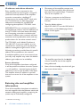
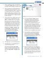
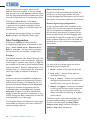
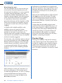
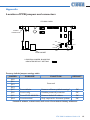
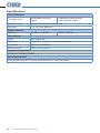
VTX-WM1 Web Monitor Card Installation and User Manual 2 VTX-WM1 Installation Guide v1.0 Contents Introduction....................................................................4 Applicability................................................................................................ 4 What’s in the box..................................................................................... 4 Installation......................................................................5 Preamble..................................................................................................... 5 Installing the VTX-WM1 card................................................................ 5 Networking principles............................................................................. 7 IP addresses and address allocation................................................. 8 Server allocation................................................................................... 8 Entering site and amplifier information............................................... 8 Amplifier data – using the GUI.................................. 10 Amplifier Status....................................................................................... 11 Monitors............................................................................................... 11 Configuration...................................................................................... 11 Network status....................................................................................... 11 Site Configuration................................................................................... 12 Port No................................................................................................. 12 Login...................................................................................................... 12 Short email format............................................................................. 12 Event Log and log configuration...................................................... 12 Impedance Tests...................................................................................... 13 Configuring the Load......................................................................... 13 Scheduling the tests........................................................................... 14 Contact Page............................................................................................ 14 Location of PCB jumpers and connectors........................................ 15 VTX Series User Manual v1.0 3 Introduction Applicability Thank you for purchasing this Cloud product. The VTX-WM1 card may be fitted to the following amplifier models: The VTX-WM1 Web Monitor Card is an option for Cloud VTX Series power amplifiers. Once correctly fitted and configured, it will allow the performance and settings of the amplifier in which it is installed to be monitored at a remote location using standard Internet browsers on any PC, Mac, PDA or smartphone, without the necessity for either dedicated software or hardware. Topics in this manual include: •• how to install the VTX-WM1 in a VTX amplifier •• how to make the necessary internal connections and internal jumper changes •• how to perform the initial card configuration via an Internet browser •• how to customise the card to suit the installation •• how to use the GUI •• how to interconnect multiple amplifiers to form a network NOTE: a short video giving an overview of the installation and configuration of the VTX-WM1 is available on the Cloud website www.cloud.co.uk If fitting a VTX-WM1 for the first time, you may find it helpful to view this before commencing the installation. 4 VTX-WM1 Installation Guide v1.0 •• Cloud VTX4120 4-channel amplifier – 4 x 120 W •• Cloud VTX4240 4-channel amplifier – 4 x 240 W •• Cloud VTX4400 4-channel amplifier – 4 x 400 W Note that the VTX-WM1 is not suitable for older VTX models, such as the VTX 750, VTX 1200 or VTX 1500. What’s in the box Check that the box contains all of the following, and notify your Cloud dealer immediately in the case of any absences or evidence of damage: •• VTX-WM1 PCB card •• Rear plate (with RJ45 connector slot) •• 2 x self-tapping screws •• Quick Installation Guide Installation Remove these jumpers Preamble: The process of installing web monitor cards into VTX amplifiers is straightforward. If cards are being fitted to multiple amplifiers installed in one or more equipment racks, each rack will need to be provided with internal CAT5 wiring and an Ethernet switch. The Installation section of the manual describes in turn: i) fitting and testing cards in the amplifiers; ii) networking principles and iii) overall system configuration. VTX-WM1 card connectors Installing the VTX-WM1 card 5. Plug in the four screened cables terminating in 3-pin connectors as follows: 1. Turn off the VTX amplifiers into which the cards are to be fitted and unplug their power cables. If the amplifiers are fitted in a rack enclosure, disconnect all rear cables from one amplifier at a time, and remove it from the rack. Place the amplifier on a flat surface. 2. Remove the amplifier’s top panel. Retain the screws (eight) and the transformer bolt. 3. Locate the rear panel blanking plate, undo the two screws securing it and remove the plate. Retain the screws. CHANNEL 2 CHANNEL 3 CHANNEL 4 SPEAKER OUTPUTS 4 OHMS - MIN CH4 0V CH2 BRIDGE 3-4 CH4 ON BRIDGE 1-2 CH3 0V OFF ON 0V OFF CH3 ON BRIDGE 3-4 ON CH2 OFF 0V BRIDGE 1-2 OFF CH1 CHANNEL 1 VTX-WM1 CARD CONNECTOR UPPER REAR PCB CONNECTOR J107B J107A J207B J207A J307B J307A J407B J407A 6. Connect all the flying leads before locating the card in place. First, plug the two 7-way ribbon cables (from J805A and J806A on the VTX-WM1 card) to J805B and J806B respectively on the amplifier’s main (lower) PCB. These are located just in front of the four large capacitors; the ribbon from J805A should be plugged into J805B (the left of the pair, looking from the rear) and that from J806A to J806B. POWER ~ 40-60Hz 10% 4. On the amplifier’s upper rear PCB (Remote Vol PCB, PC331012), locate the jumpers J109, J209, J309, J409, J110, J210, J310 and J410. All of these (total 8) should be removed. (Refer to pages12 &13 of the amplifier manual for full details of amplifier jumper locations.) 7. The remainder of the VTX-WM1 card’s flying leads connect to the amplifier’s upper rear PCB. Plug the 14-way and 6-way ribbon cables at the right-hand end of the VTX-WM1 card (from J801A and J802A respectively) into Molex headers J801B and J802B on the upper rear PCB. VTX-WM1 Installation Guide v1.0 5 VTX-WM1 card’s Ethernet port to the network port on a computer using a standard CAT5 (or CAT5-e) network cable, terminated with RJ45 plugs. Either a “straight” or a “crossed” cable may be used, as the VTX-WM1 auto-detects the data lines. Power the amplifier on; it is not necessary at this stage to connect any audio inputs or outputs. Turn the computer on and check that it has a static IP address of the form 192.168.0.xxx, where xxx can be any value between 1 and 254 except 127. Launch the Internet browser normally used (e.g., Microsoft Internet Explorer, Mozilla Firefox, Safari, etc.) POWER CONNECTOR 8. The VTX-WM1 card can now be fitted in place; the two rear supports should engage with the edge of the heatsinks, and the RJ-45 Ethernet connector should protrude through the rear panel slot. The two previously empty holes in the amplifier rear panel should align with the tapped holes in the card’s rear brackets; secure the card using the two screws supplied. 9. Locate the spare internal AC cable coming from the amplifier power transformer. This will have one red and two yellow wires and will terminate in a 3-pin Molex plug. It may be cable-tied; if so, cut the tie. Plug the connector into the large 3-pin Molex header on the front left corner of the VTX-WM1 card. 10. Fix the new rear plate (supplied) over the card slot using the two screws removed in Step 3, so that the RJ-45 connector is engaged with the square hole in the plate. Replace the top cover. 11. We recommend that the amplifier is connected to a computer at this stage to check communications. Connect the 6 VTX-WM1 Installation Guide v1.0 12. Type the card’s default IP address 192.168.0.127 - into the URL field of the browser, and the screen shown below should appear: The amplifier type listed in the Model column should be that of the amplifier in use. This confirms that the data communications section of the card is operating correctly. The card’s IP address can be changed subsequently, and this procedure is discussed in “Entering site and amplifier information” on page 8. 13. Close the browser application. The amplifier may now be disconnected from the computer and powered off. Reinstall in the rack and reconnect all rear cables. 14. Repeat the above procedure for the remaining VTX amplifiers. Networking principles The VTX-WM1 card communicates with a computer – or the building’s IT system - using standard IP protocols over Ethernet. Physically, connections are made using CAT-5 cabling (4-pair UTP) terminated with RJ-45 connectors. If only one amplifier is to be used, it may be connected directly to a computer (as in Step 11 of the Installation Procedure), or connected to the IT infrastructure once it has been assigned a compatible IP address. In systems where more than one VTX amplifier is being installed in a rack (or racks), each rack should ideally* contain an Ethernet switch (10/100baseT or 10/100/1000baseT). This should have a minimum of (N+2) ports, where N is the number of amplifiers the rack contains. Each amplifier’s VTX-WM1 card should be connected to a port on the switch, using a standard CAT-5 network cable. The switch should then be connected into the building’s IT infrastructure at the nearest convenient point via structured cabling. FIBRE or CAT5 SWITCH FIBRE or CAT5 SWITCH SWITCH EXISTING BUILDING IT INFRASTRUCTURE SWITCH SWITCH SWITCH VTX #1 VTX #6 VTX #11 VTX #2 VTX #7 VTX #12 VTX #3 VTX #8 VTX #13 VTX #4 VTX #9 VTX #14 VTX #5 VTX #10 VTX #15 RACK 1 RACK 2 ANY COMPUTER ON NETWORK RACK 3 As many amplifiers and racks as required can be networked in this way, and these may, of course, be anywhere in the building. The only requirement is that each rack switch is connected to the same building network, so that all amplifiers in the system are accessible from a computer elsewhere on the network. * Amplifiers in multiple racks may be wired to a single Ethernet switch in one (adjacent) rack if wished, though this will necessitate a significant amount of additional CAT5 cabling. VTX-WM1 Installation Guide v1.0 7 IP addresses and address allocation Every amplifier to be connected to the computer network must be given a unique IP (Internet Protocol) address. If the amplifiers are to be connected to a building’s IT infrastructure, the installer MUST check with the IT administrator to determine which addresses are available for use BEFORE configuring the amplifiers’ VTX-WM1 cards. IMPORTANT: Do not connect any amplifiers to the Ethernet network until the addresses of their VTX-WM1 cards have been individually set. Connecting more than one device with the same IP address onto a network will have anomalous and unpredictable results and may produce havoc for the other network users! 1. Disconnect all the amplifiers except one from the Ethernet switch. Also disconnect the switch from the building’s IT network. Turn all the amplifiers on. 2. Connect a computer to the Ethernet switch and launch its normal Internet browser. 3. Type the default address http://192.168.0.127 into the URL field of the browser, and the Home page shown below should appear: The VTX-WM1 card’s default IP address is 192.168.0.127. If only one amplifier is to be connected for monitoring, you may leave this address unchanged and ignore much of the following procedure, provided that this specific address will be available on the network. If multiple amplifiers are to be monitored, one (but only one) amplifier may retain this default address, again subject to its availability. Server allocation Once all the amplifiers have been configured, it will be possible to address the entire system – i.e. all amplifiers – by entering any of the IP addresses in use into the browser’s URL field. The amplifier whose IP address is used will then act as a server for all the amplifiers in the system. Entering site and amplifier information Once all the amplifiers have been reinstalled in the rack together with the Ethernet switch and network cabling, each amplifier comprising the system may be individually configured: * IT Network terminology 8 VTX-WM1 Installation Guide v1.0 The amplifier type listed in the Model column should be that of the amplifier being addressed. 4. Next, click the Config tab, which will give the screen shown below: 5. Enter a suitable name for the installation in the Site Name field (e.g., name of the customer and/or building or location, etc.) 6. Use of a password is recommended as it will prevent unauthorised access to the network configuration pages - monitoring of amplifier performance and settings is always possible. Enter a password in the Site Password field. A password may be up to 64 characters in length and will be case sensitive. 7. If the network has an SMTP mail server, you may enter an email address in the Email target field. This will enable fault reports to be sent to this address automatically. For this feature to work, IP addresses for the mail server and the system Gateway are also needed; you should obtain this information from the IT System administrator. Enter these addresses in the Mail Server IP and Gateway IP fields respectively by clicking the two Set buttons, which will open the IP address configuration dialogue box: 10. The first field, Unit Name, permits the amplifier itself to be named. This is extremely useful with large systems employing multiple amplifiers. Each amplifier will be referenced by the Unit Name on all the GUI pages thereafter. The name may, for example, be the area of the building where the speakers that the amplifier is driving are located. (The Unit Name may be up to 100 characters in length, but note it will be truncated to 16 characters for the amplifier button label.) 11. If the amplifier is to have an IP address other than the default, click the Set button adjacent to the IP address field, which will open the IP address configuration dialogue box: 8.Click Apply to close the dialogue box. 9. Click Apply (on the Config page) to confirm the data entered. Click the blue Cloud Amplifier button in the left-hand pane (only one amplifier will be listed at present). This opens the Amplifier Properties page: 12. Enter the IP address for the amplifier in the four numeric fields and click Apply. We strongly recommend that you keep a careful record of all IP addresses used, and also write the address in the IP space on the VTX-WM1’s rear panel (or print a label for this purpose). VTX-WM1 Installation Guide v1.0 9 13. The VTX-WM1 card has an on-board clock/calendar, which needs to be set for the Event Log to be meaningful. The default Current Time will be midnight on Jan. 1st. 2000; click the adjacent Set button to open the Clock setting window. Enter the current date and time in the five fields in the format yyyy-mm-dd hh:mm and click Apply. 14.Click Apply on the Amplifier Properties page to confirm the data entered. 15. Enter the amplifier’s new IP address into the browser’s URL field to re-establish communication with the card. The Home page will now confirm the Site and Amplifier Names which were entered, and there will also be a green tick and “OK” in the amplifier’s Network field to confirm communication with the new address. The CloudNET page will also confirm that the amplifier has been designated Server status. the new amplifier with its blue button (it will still be named “Cloud Amplifier”). Then repeat the procedure above, starting at Step 10. 18. Continue this procedure, adding one amplifier at a time, until all the amplifiers in the system are registered on the browser. Note each time, that the PC may take a few moments to recognise that a VTX-WM1 card has had its address changed; this is normal. 19. When all the amplifiers have been configured, the Ethernet switch may be reconnected to the building’s IT network. It is recommended that access to the amplifiers is re-checked by entering the IP address of one of them from a computer elsewhere on the network. Amplifier data – using the GUI Once the amplifiers have been configured, amplifier performance and settings can be monitored from the web browser of any computer on the network. To access the system, enter the IP address of any of the amplifiers into the URL field of the web browser. This will show the Home Page, an example of which is shown below: 16. Connect the next amplifier’s VTX-WM1 card to the Ethernet switch. Select the Home page tab, and after a few seconds, the amplifier’s details will be added to the amplifier list. On the CloudNET tab, you will see that the additional amplifier has a red cross in the Server column – the first amplifier retains Server status because the browser is still using its IP address. 17. The additional amplifier will have the default IP address; this will need to be changed. Click the Config tab, and select 10 VTX-WM1 Installation Guide v1.0 The Home Page gives a overview of the entire system. All amplifiers are listed, by the names that they were given during configuration. The Model type is confirmed, and any Network faults. If an amplifier cannot be found on the network, a red cross appears in the Network column, as shown below: Configuration: •• High-pass filter – rear panel switch setting •• Bridge mode – rear panel switch setting •• Input linking – rear panel switch setting •• Current level control – rear panel rotary control setting •• Current external level control – RL-1 remote control plate setting (if fitted) Colours are used to indicate amplifier conditions: A green indicator in the Channels columns confirms that each channel of each amplifier is operating normally. Amplifier Status Each amplifier’s performance and settings may be checked in greater detail by clicking on its name in the Unit Name column. This gives a display as below: •• Green: •• Yellow: •• Red: Normal operation Becoming marginal Outside acceptable limits In the Config area, a green tick indicates that a function activated by one of the rear panel switches is ON, a red cross indicates that it is OFF. The settings of the local and remote level controls are shown as horizontal bargraphs, with the “segments” changing from grey to green as the level controls are advanced. This page can be closed by clicking on any other tab, or your browser’s “Back” button. Network status Clicking the CloudNET tab opens the Network Overview page: Each channel of the amplifier reports its status as follows: Monitors: •• Internal heatsink temperature •• Fan speed •• Clip limiter circuitry status •• Input signal level (in dBu) The CloudNET page lists all amplifiers on the system, together with confirmation of each VTX-WM1 Installation Guide v1.0 11 unit’s network status, server status and IP address. Only one amplifier in the list should have a green tick in the Server column. Note that this page automatically refreshes every few seconds, as the network is continuously polled. Clicking the Test button in the Test connection column causes the amplifier in question to be polled immediately (often referred to as “pinging”); it will then report its current status. As with the Home page, clicking on a Unit Name will open the Amplifier Status page. Site Configuration Clicking the Config tab opens the Site Configuration page. Some of the fields on this page – Site Name, Site Password and Email target - will have been completed during initial site and amplifier configuration. Port No. The default value for this field is 80, which will be appropriate for most installations. However, some large IT systems may require a different port number to be used to avoid conflicts. Please check with the IT system’s administrator as to whether this is a requirement. An alternative value may simply be entered if necessary. Login Access to the site and amplifier configuration pages may be password-protected to prevent unauthorised changes to IP addresses, etc. If a password has been defined and the Request login box checked, the password will be requested before the Config tab is opened. Request login is active by default. After logging in with the password, remember to log out by clicking the Log out button at the top of the amplifier list on this page. The Amplifier Status and Network Status pages are available at all times to all users, without a password being required. 12 VTX-WM1 Installation Guide v1.0 Short email format If this box is left unchecked (the default), any emails sent to the target address will only contain abridged site information, and not a full description of any fault conditions (see below). Event Log and log configuration A log is maintained for each amplifier on the system. The log records power-on and poweroff, over-temperature, impedance test pass/ fail and email alert failures, all against the onboard clock/calendar. The Event logging pane on the Site Configuration page lets you define which of these events are to be recorded and whether any (or all) of them should generate email alerts. For each of the six event types, one of the following options may be set: •• None – events of this type are ignored •• Log only – events of this type are recorded in the log •• Log & email – events are recorded in the log and also entered in an alert email, but the email is not sent at this time. •• Email Trigger – events are recorded in the log, and the alert email is sent; this will contain the current event and any events recorded via the Log & email option above. The Event log for a particular amplifier may be inspected by clicking on the amplifier’s button in the list (opens the Amplifier Properties page), and then clicking on Event Log below the button. impedance at the frequency to be used. The upper pane of the Test List page is concerned with this initialisation. Impedance Tests The VTX-WM1 card includes a variable frequency test oscillator which may be programmed to apply a test tone (at 40 dB below the amplifier’s maximum output level) to the amplifier output at a future date and time, and, if desired, at regular intervals thereafter. (It is recommended that tests are scheduled for the hours of building non-occupation). The amplifier output voltage and current are monitored during the test and hence the load impedance checked. This gives the engineer a first-line confirmation that all the speakers connected to each amplifier channel are present, connected and functional. Clicking Tests (click the amplifier button first) opens the Test List page for the amplifier: In order for the impedance tests to be meaningful, an initial Load Configuration test must be run, to establish a reference Configuring the Load The amplifier must be powered on and each channel connected correctly to its normal speaker(s). Select each channel in use from the drop-down list under Channel. (If any channels are in Bridge Mode, select the lowernumbered channel of the pair.) Select the frequency to be used for the test from the drop-down list under Frequency. If using a bi-amped (or tri-amped, etc.) speaker system, the frequency for each channel will need to chosen to match the relevant driver type. The frequency selected should be approximately in the middle of the frequency response range of the speakers/drivers connected to the channel. Consideration should be also be taken of any loudspeaker enclosure resonant frequencies – these may be particularly evident at low frequencies, and should be avoided, as their use will give misleading results. Click the Config button. This will generate a dialogue box warning that a test tone is about to be fed through the audio system. Click OK if you are happy for this to occur. A progress bar is displayed, and when the test is complete an impedance value will be displayed in the Expected field. To re-check the expected value, set a Tolerance value (30% is recommended initially) and click the Test button. A second test will be run, and the results displayed. The Remove button may be used to cancel the current reference impedance value for the selected channel. This should be done if, for example, a loudspeaker has been removed or replaced. VTX-WM1 Installation Guide v1.0 13 Scheduling the tests The test scheduler lets you set the date and time at which the next impedance test will be executed, and whether it is to be repeated at regular intervals thereafter. It also lets you set the schedule independently for each amplifier channel, together with the frequency to be used and the tolerance to be applied. An impedance measurement outside the prescribed tolerance will be classified as a Test Failure, be recorded in the amplifier log and/ or generate an email alert (if set up in Event Logging). In systems with multiple amplifiers, each amplifier may run its own set of tests simultaneously if wished. However, it is not possible to run tests on more than one channel within each amplifier simultaneously, so test times for the channels in any one amplifier should be carefully staggered. To add a test to the scheduler, select a channel from the drop-down list under Scheduled Tests, select the frequency to be used (see remarks above), and select a tolerance; 30% is recommended initially. Click the calendar symbol to open the test scheduling calendar window. Select the date on which the next test is to be run by clicking on it. The months can be scrolled through with the ‘|<’ and ‘>|’ buttons at the top. Next select the time at which the test is to be run using the Hours and Minutes spin boxes. 14 VTX-WM1 Installation Guide v1.0 If the test is to be repeated on a regular basis, select the repetition rate using the lower set of date/time spin boxes. Note that test intervals can be set in increments of one minute up to several years. When all the scheduling data has been entered, click Apply to close the window. The date and time at which this particular test will be next run is displayed. To add the test item to the schedule, click the ‘+’ button at the end of the test item line. Further tests may be added using the same procedure. Tests may be added with any or all of the same settings, or different settings may be used. A test item may be deleted from the schedule by clicking its ‘x’ button. When the test schedule for the amplifier is complete, the process should be repeated for the other amplifiers comprising the system. Contact Page Clicking the Contact Us tab links directly to the contact page of the Cloud website. This includes all company contact details, including a query form. Please make use of this facility if there are any technical points arising from your VTX-WM1 installation on which you need assistance. Appendix Location of PCB jumpers and connectors POWER CONNECTOR Factory default jumper settings table JUMPER J810 J811 J812 J813 J817 PURPOSE FUNCTION DEFAULT Reserved Force defaults Restores all factory default settings* Off J816 Force config Disables password protection Off J815 J814 Force IP 192.168.0.126 Force bootload Restores default IP address Only required for firmware updates Off Off * Default IP address, subnet mask, mail server IP and default fateway addresses. VTX-WM1 Installation Guide v1.0 15 Specifications Tone Generator Test Signal Level 40 dB below max amp output Injected post level controls, other channels muted. Frequency range 60 Hz to 20 kHz in 1/3-octave steps Sensitivity 1 to 100 Ohm detection Signal detector Sensitivity ‑30 dBu to +10 dBu 20 Hz to 20 kHz Networking DHCP Not supported Data rates 10 BaseT or 100 Base T (automatic selection) Connector RJ45; Auto MDI/MDIX eMail protocols SMTP (no encryption) Supported Amplifiers VTX4120,VTX4240,VTX4400 Recordable Events Over temperature (90°C), Power on/off, Email error, Load Test pass/fail 16 VTX-WM1 Installation Guide v1.0