1
CÓPIA NÃO CONTROLADA
M000/M009
SERVICE MANUAL
003787MIU
CÓPIA NÃO CONTROLADA
CÓPIA NÃO CONTROLADA
CÓPIA NÃO CONTROLADA
CÓPIA NÃO CONTROLADA
M000/M009
SERVICE MANUAL
CÓPIA NÃO CONTROLADA
CÓPIA NÃO CONTROLADA
CÓPIA NÃO CONTROLADA
CÓPIA NÃO CONTROLADA
M000/M009
SERVICE MANUAL
003787MIU
CÓPIA NÃO CONTROLADA
CÓPIA NÃO CONTROLADA
CÓPIA NÃO CONTROLADA
CÓPIA NÃO CONTROLADA
It is the reader's responsibility when discussing the information contained
within this document to maintain a level of confidentiality that is in the best
interest of Ricoh Americas Corporation and its member companies.
NO PART OF THIS DOCUMENT MAY BE REPRODUCED IN ANY
FASHION AND DISTRIBUTED WITHOUT THE PRIOR
PERMISSION OF RICOH AMERICAS CORPORATION.
All product names, domain names or product illustrations, including
desktop images, used in this document are trademarks, registered
trademarks or the property of their respective companies.
They are used throughout this book in an informational or editorial fashion
only and for the benefit of such companies. No such use, or the use of
any trade name, or web site is intended to convey endorsement or other
affiliation with Ricoh products.
© 2008 RICOH Americas Corporation. All rights reserved.
CÓPIA NÃO CONTROLADA
CÓPIA NÃO CONTROLADA
CÓPIA NÃO CONTROLADA
CÓPIA NÃO CONTROLADA
WARNING
The Service Manual contains information
regarding service techniques, procedures,
processes and spare parts of office equipment
distributed by Ricoh Americas Corporation.
Users of this manual should be either service
trained or certified by successfully completing a
Ricoh Technical Training Program.
Untrained and uncertified users utilizing
information contained in this service manual to
repair or modify Ricoh equipment risk personal
injury, damage to property or loss of warranty
protection.
Ricoh Americas Corporation
CÓPIA NÃO CONTROLADA
CÓPIA NÃO CONTROLADA
CÓPIA NÃO CONTROLADA
CÓPIA NÃO CONTROLADA
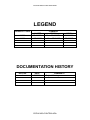
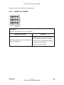
LEGEND
PRODUCT CODE
M000
M009
LANIER
SP 3300DN
SP 3300D
COMPANY
RICOH
Aficio SP 3300DN
Aficio SP 3300D
SAVIN
SP 3300DN
SP 3300D
DOCUMENTATION HISTORY
REV. NO.
*
DATE
05/2008
COMMENTS
Original Printing
CÓPIA NÃO CONTROLADA
CÓPIA NÃO CONTROLADA
CÓPIA NÃO CONTROLADA
CÓPIA NÃO CONTROLADA
M000/M009
TABLE OF CONTENTS
INSTALLATION
1. INSTALLATION .......................................................................1-1
1.1 INSTALLATION REQUIREMENTS.......................................................1-1
PREVENTIVE MAINTENANCE
2. PREVENTIVE MAINTENANCE ...............................................2-1
2.1 PM INTERVALS....................................................................................2-1
REPLACEMENT AND ADJUSTMENT
3. REPLACEMENT & ADJUSTMENT .........................................3-1
3.1 GENERAL PRECAUTIONS ON DISASSEMBLY..................................3-1
3.1.1 CHECK POINTS FOR SERVICING .............................................3-1
3.1.2 RELEASING PLASTIC LATCHES ...............................................3-1
3.2 COVER UNIT ........................................................................................3-2
3.2.1 CASSETTE AND FRONT COVER ..............................................3-2
3.2.2 DUPLEX UNIT AND REAR COVER ............................................3-3
3.2.3 TOP COVER................................................................................3-4
3.2.4 LEFT AND RIGHT COVER..........................................................3-5
3.3 FUSER..................................................................................................3-6
3.4 LSU (LASER SCANNING UNIT)...........................................................3-8
3.5 DRIVE ...................................................................................................3-9
3.6 HVPS/SMPS/MAIN BOARD ...............................................................3-10
3.6.1 HVPS (HIGH VOLTAGE POWER SUPPLY) .............................3-10
3.6.2 SMPS (SWITCHING MODE POWER SUPPLY)........................3-11
3.6.3 MAIN BOARD ............................................................................3-12
3.7 PAD-HOLDER.....................................................................................3-13
3.8 TRANSFER ROLLER .........................................................................3-15
SM
i
CÓPIA NÃO CONTROLADA
M000/M009
CÓPIA NÃO CONTROLADA
3.9 PICK-UP ROLLER ..............................................................................3-16
TROUBLESHOOTING
4. TROUBLESHOOTING .............................................................4-1
4.1 PROCEDURE OF CHECKING SYMPTOMS........................................4-1
4.2 SYMPTOMS, CAUSES, AND SOLUTIONS OF BAD IMAGES ............4-2
4.2.1 VERTICAL BLACK LINE AND BAND ..........................................4-2
4.2.2 VERTICAL WHITE LINE ..............................................................4-3
4.2.3 HORIZONTAL BLACK BAND ......................................................4-4
4.2.4 BLACK/WHITE SPOT ..................................................................4-5
4.2.5 LIGHT IMAGE..............................................................................4-6
4.2.6 DARK IMAGE OR BLACK PAGE ................................................4-7
4.2.7 UNEVEN DENSITY .....................................................................4-8
4.2.8 BACKGROUND ...........................................................................4-9
4.2.9 GHOST (1).................................................................................4-10
4.2.10 GHOST (2) ...........................................................................4-11
4.2.11 GHOST (3): FUSER .............................................................4-12
4.2.12 STAINS ON THE FACE OF PAGE ......................................4-13
4.2.13 STAINS ON THE BACK OF PAGE ......................................4-14
4.2.14 BLANK PAGE PRINT OUT (1) .............................................4-15
4.2.15 BLANK PAGE PRINT OUT (2) .............................................4-16
4.3 DISCHARGE SYMPTOMS, CAUSES, AND SOLUTIONS .................4-17
4.3.1 WRONG PRINT POSITION .......................................................4-17
4.3.2 JAM 0.........................................................................................4-18
4.3.3 JAM 1.........................................................................................4-19
4.3.4 JAM 2.........................................................................................4-20
4.3.5 DUPLEX JAM ............................................................................4-21
4.3.6 MULTI-FEEDING .......................................................................4-22
4.3.7 PAPER ROLLED IN THE FUSER..............................................4-23
4.3.8 PAPER ROLLED ON THE OPC DRUM.....................................4-24
4.4 MALFUNCTION CAUSES AND SOLUTIONS ....................................4-25
4.4.1 FUSER ERROR.........................................................................4-25
4.4.2 LSU (LASER SCANNING UNIT) ERROR..................................4-25
4.4.3 MALFUNCTION OF THE GEAR OF THE FUSER DUE TO
MELTING ............................................................................................4-26
M000/M009
ii
CÓPIA NÃO CONTROLADA
SM
CÓPIA NÃO CONTROLADA
4.4.4 PAPER EMPTY .........................................................................4-26
4.4.5 PAPER EMPTY WITHOUT INDICATION ..................................4-27
4.4.6 COVER OPEN ...........................................................................4-27
4.4.7 NO ERROR MESSAGE WHEN THE COVER IS OPEN............4-28
4.4.8 DEFECTIVE MOTOR OPERATION ..........................................4-28
4.4.9 NO POWER ...............................................................................4-29
4.4.10 CURVED VERTICAL LINE...................................................4-29
4.5 SOFTWARE (ERRORS, SYMPTOMS, CAUSES AND SOLUTIONS)4-30
4.5.1 PRINTER NOT WORKING (1)...................................................4-30
4.5.2 PRINTER NOT WORKING (2)...................................................4-32
4.5.3 ABNORMAL PRINTING.............................................................4-33
4.5.4 SPOOL ERROR.........................................................................4-34
4.6 CLEARING PAPER JAMS ..................................................................4-35
4.6.1 PAPER FEED AREA .................................................................4-35
Tray 1 ............................................................................................4-35
Optional tray 2 ...............................................................................4-36
In the manual tray..........................................................................4-37
4.6.2 PRINT CARTRIDGE AREA .......................................................4-38
4.6.3 PAPER EXIT AREA ...................................................................4-39
4.6.4 DUPLEX UNIT AREA ................................................................4-40
Duplex Jam 0 ................................................................................4-40
Duplex Jam 1 ................................................................................4-41
4.6.5 TIPS TO AVOID PAPER JAMS .................................................4-42
4.7 PERIODIC DEFECTIVE IMAGE .........................................................4-43
SERVICE TABLES
5. SERVICE TABLES...................................................................5-1
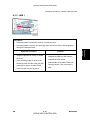
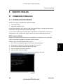
5.1 FIRMWARE DOWNLOAD ....................................................................5-1
5.1.1 DOWNLOAD PROCEDURE ........................................................5-1
DOS Command Mode .....................................................................5-1
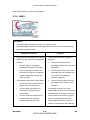
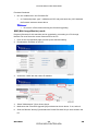
WIM (Web Image Monitor) mode ....................................................5-2
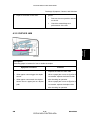
5.1.2 FIRMWARE RECOVERY PROCEDURE.....................................5-3
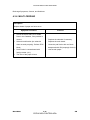
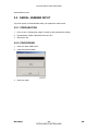
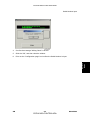
5.2 SERIAL NUMBER INPUT .....................................................................5-4
5.2.1 PREPARATION ...........................................................................5-4
5.2.2 PROCEDURE ..............................................................................5-4
SM
iii
CÓPIA NÃO CONTROLADA
M000/M009
CÓPIA NÃO CONTROLADA
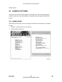
5.3 SAMPLE PATTERN..............................................................................5-6
5.3.1 DEMO PAGE ...............................................................................5-6
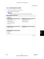
5.3.2 CONFIGURATION PAGE ............................................................5-7
DETAILED DESCRIPTIONS SECTION
6. DETAILED DESCRIPTIONS....................................................6-1
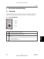
6.1 OVERVIEW...........................................................................................6-1
6.1.1 KEY OPERATION........................................................................6-1
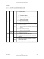
6.1.2 LED STATUS ERROR MESSAGE ..............................................6-2
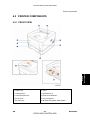
6.2 PRINTER COMPONENTS....................................................................6-3
6.2.1 FRONT VIEW ..............................................................................6-3
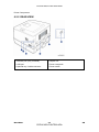
6.2.2 REAR VIEW.................................................................................6-4
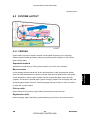
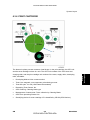
6.3 SYSTEM LAYOUT ................................................................................6-5
6.3.1 FEEDING .....................................................................................6-5
Separation method ..........................................................................6-5
Basic cassette .................................................................................6-5
Pick-up roller ...................................................................................6-5
Registration roller ............................................................................6-5
By-pass tray ....................................................................................6-6
Duplex unit ......................................................................................6-6
Paper Feed Unit ..............................................................................6-6
6.3.2 TRANSFER..................................................................................6-6
6.3.3 DRIVE ..........................................................................................6-6
6.3.4 FUSER.........................................................................................6-7
Thermostat ......................................................................................6-7
Heat roller........................................................................................6-7
Pressure roller .................................................................................6-7
Items for safety................................................................................6-7
6.3.5 LSU (LASER SCANNER UNIT) ...................................................6-8
6.3.6 PRINT CARTRIDGE ....................................................................6-9
6.4 ENGINE HARDWARE SPECIFICATIONS..........................................6-10
6.4.1 ENGINE FIRMWARE.................................................................6-10
Driver.............................................................................................6-10
Transfer .........................................................................................6-10
Fusing ...........................................................................................6-10
M000/M009
iv
CÓPIA NÃO CONTROLADA
SM
CÓPIA NÃO CONTROLADA
LSU ...............................................................................................6-11
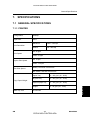
SPECIFICATIONS
7. SPECIFICATIONS....................................................................7-1
7.1 GENERAL SPECIFICATIONS ..............................................................7-1
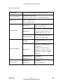
7.1.1 PRINTER .....................................................................................7-1
7.1.2 OPTION .......................................................................................7-3
7.2 CONTROLLER......................................................................................7-4
7.3 HANDLING PAPER ..............................................................................7-5
APPENDIX
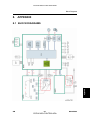
8. APPENDIX ...............................................................................8-1
8.1 BLOCK DIAGRAMS..............................................................................8-1
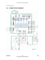
8.2 CONNECTION DIAGRAM ....................................................................8-2
SM
v
CÓPIA NÃO CONTROLADA
M000/M009
CÓPIA NÃO CONTROLADA
CÓPIA NÃO CONTROLADA
CÓPIA NÃO CONTROLADA
TROUBLESHOOTING
DETAILED DESCRIPTIONS
TAB
POSITION 7
SPECIFICATIONS
TAB
POSITION 6
TAB
POSITION 5
SERVICE TABLES
TAB
POSITION 3
REPLACEMENT AND ADJUSTMENT
TAB
POSITION 4
PREVENTIVE MAINTENANCE
TAB
POSITION 2
TAB
POSITION 1
INSTALLATION
TAB
POSITION 8
APPENDIX
CÓPIA NÃO CONTROLADA
CÓPIA NÃO CONTROLADA
CÓPIA NÃO CONTROLADA
CÓPIA NÃO CONTROLADA
Read This First
Precautions
In order to prevent accidents and to prevent damage to the equipment, please read the
precautions listed below carefully before servicing the printer and follow them closely.
Safety Warning
1.
Only to be serviced by appropriately qualified service engineers.
High voltages and lasers inside this product are dangerous. This printer should
only be serviced by a suitably trained and qualified service engineer.
2.
Use only genuine replacement parts
There are no user serviceable parts inside the printer. Do not make any
unauthorized changes or additions to the printer, these could cause the printer to
malfunction and create electric shock or fire hazards.
3.
Laser Safety Statement
The Printer is certified in the U.S. to conform to the requirements of DHHS 21 CFR,
chapter 1 Subchapter J for Class 1(1) laser products, and elsewhere, it is certified
as a Class I laser product conforming to the requirements of IEC 825. Class I laser
products are not considered to be hazardous. The laser system and printer are
designed so there is never any human access to laser radiation above a Class I
level during normal operation, user maintenance, or prescribed service condition.
Never operate or service the printer with the protective cover removed from
Laser/Scanner assembly. The reflected beam, although invisible, can damage
your eyes. When using this product, these basic safety pre-cautions should
always be followed to reduce risk of fire, electric shock, and injury to persons.
CÓPIA NÃO CONTROLADA
CÓPIA NÃO CONTROLADA
Caution for safety
Toxic material
This product contains toxic materials that could cause illness if ingested.
1.
If the LCD control panel is damaged, it is possible for the liquid inside to leak. This
liquid is toxic. Contact with the skin should be avoided, wash any splashes from eyes
or skin immediately and contact your doctor. If the liquid gets into the mouth or is
swallowed, see a doctor immediately.
2.
Please keep toner cartridges away from children. The toner powder contained in the
toner cartridge may be harmful and if swallowed, you should contact a doctor.
CÓPIA NÃO CONTROLADA
CÓPIA NÃO CONTROLADA
Electric Shock and Fire Safety Precautions
Failure to follow the following instructions could cause electric shock or potentially cause a
fire.
1.
Use only the correct voltage, failure to do so could damage the printer and potentially
cause a fire or electric shock.
2.
Use only the power cable supplied with the printer. Use of an incorrectly specified
cable could cause the cable to overheat and potentially cause a fire.
3.
Do not overload the power socket, this could lead to overheating of the cables inside
the wall and could lead to a fire.
4.
Do not allow water or other liquids to spill into the printer, this can cause electric shock.
Do not allow paper clips, pins or other foreign objects to fall into the printer these could
cause a short circuit leading to an electric shock or fire hazard..
5.
Never touch the plugs on either end of the power cable with wet hands, this can cause
electric shock. When servicing the printer remove the power plug from the wall socket.
6.
Use caution when inserting or removing the power connector. The power connector
must be inserted completely otherwise a poor contact could cause overheating
possibly leading to a fire. When removing the power connector grip it firmly and pull.
7.
Take care of the power cable. Do not allow it to become twisted, bent sharply round
corners or other wise damaged. Do not place objects on top of the power cable. If the
power cable is damaged it could overheat and cause a fire or exposed cables could
cause an electric shock. Replace a damaged power cable immediately, do not reuse or
repair the damaged cable. Some chemicals can attack the coating on the power cable,
weakening the cover or exposing cables causing fire and shock risks.
8.
Ensure that the power sockets and plugs are not cracked or broken in any way. Any
such defects should be repaired immediately. Take care not to cut or damage the
power cable or plugs when moving the machine.
9.
Use caution during thunder or lightening storms. We recommend that this machine be
disconnected from the power source when such weather conditions are expected. Do
not touch the machine or the power cord if it is still connected to the wall socket in
these weather conditions.
10. Avoid damp or dusty areas, install the printer in a clean well ventilated location. Do not
position the machine near a humidifier. Damp and dust build up inside the machine can
lead to overheating and cause a fire.
CÓPIA NÃO CONTROLADA
CÓPIA NÃO CONTROLADA
11. Do not position the printer in direct sunlight. This will cause the temperature inside the
printer to rise possibly leading to the printer failing to work properly and in extreme
conditions could lead to a fire.
12. Do not insert any metal objects into the machine through the ventilator fan or other part
of the casing, it could make contact with a high voltage conductor inside the machine
and cause an electric shock.
Handling Precautions
The following instructions are for your own personal safety, to avoid injury and so as not to
damage the printer
1.
Ensure the printer is installed on a level surface, capable of supporting its weight.
Failure to do so could cause the printer to tip or fall.
2.
The printer contains many rollers, gears and fans. Take great care to ensure that you
do not catch your fingers, hair or clothing in any of these rotating devices.
3.
Do not place any small metal objects, containers of water, chemicals or other liquids
close to the printer which if spilled could get into the machine and cause damage or a
shock or fire hazard.
4.
Do not install the machine in areas with high dust or moisture levels, beside on open
window or close to a humidifier or heater. Damage could be caused to the printer in
such areas.
5.
Do not place candles, burning cigarettes, etc on the printer. These could cause a fire.
CÓPIA NÃO CONTROLADA
CÓPIA NÃO CONTROLADA
Assembly/ Disassembly Precautions
Replace parts carefully, always use genuine parts. Take care to note the exact location of
parts and also cable routing before dismantling any part of the machine. Ensure all parts
and cables are replaced correctly.
Please carry out the following procedures before dismantling the printer or replacing any
parts.
1.
Check the contents of the machine memory and make a note of any user settings.
These will be erased if the main board or network card is replaced.
2.
Ensure that power is disconnected before servicing or replacing any electrical parts.
3.
Disconnect printer interface cables and power cables.
4.
Only use approved spare parts. Ensure that part number, product name, any voltage,
current or temperature rating are correct.
5.
When removing or re-fitting any parts do not use excessive force, especially when
fitting screws into plastic.
6.
Take care not to drop any small parts into the machine.
7.
Handling of the OPC Drum:
The OPC Drum can be irreparably damaged if it is exposed to light. Take care not
to expose the OPC Drum either to direct sunlight or to fluorescent or incandescent
room lighting. Exposure for as little as five minutes can damage the surface’s
photoconductive properties and will result in print quality degradation. Take extra
care when servicing the printer. Remove the OPC Drum and store it in a black bag
or other lightproof container. Take care when working with the covers (especially
the top cover) open as light is admitted to the OPC area and can damage the OPC
Drum.
Take care not to scratch the green surface of OPC Drum Unit. If the green surface
of the Drum Cartridge is scratched or touched the print quality will be
compromised.
CÓPIA NÃO CONTROLADA
CÓPIA NÃO CONTROLADA
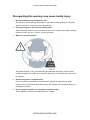
Disregarding this warning may cause bodily injury
1.
Be careful with the high temperature part.
The fuser unit works at a high temperature. Use caution when working on the printer.
Wait for the fuser to cool down before disassembly.
2.
Do not put fingers or hair into the rotating parts.
When operating a printer, do not put hand or hair into the rotating parts (Paper feeding
entrance, motor, fan, etc.). If do so, you may get harm.
3.
When you move the printer.
This printer weighs 7.87kg. Use safe lifting and handling techniques. Use the lifting
handles located on each side of the machine. Back injury could be caused if you do not
lift carefully.
4.
Ensure the printer is installed safely.
Ensure the printer is installed on a level surface, capable of supporting its weight.
Failure to do so could cause the printer to tip or fall, possibly causing personal injury or
damaging the printer.
5.
Do not install the printer on a sloping or unstable surface.
After installation, double check that the printer is stable.
CÓPIA NÃO CONTROLADA
CÓPIA NÃO CONTROLADA
ESD Precautions
Certain semiconductor devices can be easily damaged by static electricity. Such
components are commonly called “Electrostatically Sensitive (ES) Devices”, or ESDs.
Examples of typical ESDs are: integrated circuits, some field effect transistors, and
semiconductor “chip” components.
The techniques outlined below should be followed to help reduce the incidence of
component damage caused by static electricity.
Be sure that no power is applied to the chassis or circuit, and observe all other
safety precautions.
1.
Immediately before handling a semiconductor component or semiconductor-equipped
assembly, drain off any electrostatic charge on your body by touching a known earth
ground. Alternatively, employ a commercially available wrist strap device, which should
be removed for personal safety prior to applying power to the unit under test.
2.
After removing an electrical assembly equipped with ESDs, place the assembly on a
conductive surface, such as aluminum or copper foil, or conductive foam, to prevent
electrostatic charge buildup in the vicinity of the assembly.
3.
Use only a grounded tip soldering iron to solder or desolder ESDs.
4.
Use only an “anti-static” solder removal device. Some solder removal devices not
classified as “anti-static” can generate electrical charges sufficient to damage ESDs.
5.
Do not use Freon-propelled chemicals. When sprayed, these can generate electrical
charges sufficient to damage ESDs.
6.
Do not remove a replacement ESD from its protective packaging until immediately
before installing it. Most replacement ESDs are packaged with all leads shorted
together by conductive foam, aluminum foil, or a comparable conductive material.
7.
Immediately before removing the protective shorting material from the leads of a
replacement ESD, touch the protective material to the chassis or circuit assembly into
which the device will be installed.
8.
Maintain continuous electrical contact between the ESD and the assembly into which it
will be installed, until completely plugged or soldered into the circuit.
9.
Minimize bodily motions when handling unpackaged replacement ESDs. Normal
motions, such as the brushing together of clothing fabric and lifting one’s foot from a
carpeted floor, can generate static electricity sufficient to damage an ESD.
CÓPIA NÃO CONTROLADA
CÓPIA NÃO CONTROLADA
CÓPIA NÃO CONTROLADA
CÓPIA NÃO CONTROLADA
INSTALLATION
CÓPIA NÃO CONTROLADA
CÓPIA NÃO CONTROLADA
CÓPIA NÃO CONTROLADA
CÓPIA NÃO CONTROLADA
Installation
Installation Requirements
1. INSTALLATION
1.1 INSTALLATION REQUIREMENTS
For details refer to the User's Guide.
SM
1-1
CÓPIA NÃO CONTROLADA
M000/M009
CÓPIA NÃO CONTROLADA
CÓPIA NÃO CONTROLADA
CÓPIA NÃO CONTROLADA
PREVENTIVE MAINTENANCE
CÓPIA NÃO CONTROLADA
CÓPIA NÃO CONTROLADA
CÓPIA NÃO CONTROLADA
CÓPIA NÃO CONTROLADA
PM Intervals
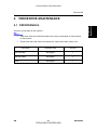
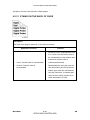
2. PREVENTIVE MAINTENANCE
There are no PM parts in this machine.
Other than the three Yield Parts listed below, there is essentially no PM required
on this product.
These three items will need to be replaced in cases where their yield is near.
Description
Expected Yield
Q'ty/unit
Pick-up Roller
50K pages
1
Transfer Roller
50K pages
1
Fuser
50K pages
1
SM
2-1
CÓPIA NÃO CONTROLADA
M000/M009
Preventive
Maintenance
2.1 PM INTERVALS
CÓPIA NÃO CONTROLADA
CÓPIA NÃO CONTROLADA
CÓPIA NÃO CONTROLADA
REPLACEMENT & ADJUSTMENT
CÓPIA NÃO CONTROLADA
CÓPIA NÃO CONTROLADA
CÓPIA NÃO CONTROLADA
CÓPIA NÃO CONTROLADA
General Precautions on Disassembly
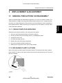
3. REPLACEMENT & ADJUSTMENT
3.1 GENERAL PRECAUTIONS ON DISASSEMBLY
When you disassemble and reassemble components, you must use extreme caution. The
close proximity of cables to moving parts makes proper routing a must. If components are
removed, any cables disturbed by the procedure must be restored as close as possible to
Replacement
Adjustment
their original positions. Before removing any component from the machine, note the cable
routing that will be affected.
3.1.1 CHECK POINTS FOR SERVICING
Whenever servicing the machine, you must perform as follows:
1.
Check to verify that documents are not stored in memory.
2.
Be sure to remove the print cartridge before you disassemble parts.
3.
Unplug the power cord.
4.
Use a flat and clean surface.
5.
Replace only with authorized components.
6.
Do not force plastic-material components.
7.
Make sure all components are in their proper position.
3.1.2 RELEASING PLASTIC LATCHES
Many of the parts are held in place with plastic latches. The latches break easily; release
them carefully. To remove such parts, press the hook end of the latch away from the part to
which it is latched.
SM
3-1
CÓPIA NÃO CONTROLADA
M000/M009
CÓPIA NÃO CONTROLADA
Cover Unit
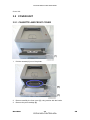
3.2 COVER UNIT
3.2.1 CASSETTE AND FRONT COVER
1.
Pull the cassette [A] out of the printer.
2.
Remove carefully the front cover [A], using caution with the hooks.
3.
Remove the print cartridge [B].
M000/M009
3-2
CÓPIA NÃO CONTROLADA
SM
CÓPIA NÃO CONTROLADA
Cover Unit
Replacement
Adjustment
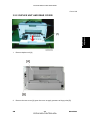
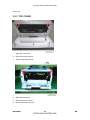
3.2.2 DUPLEX UNIT AND REAR COVER
1.
Remove duplex unit [A].
2.
Remove the rear cover [A] open the cover an apply pressure at hinge point [B].
SM
3-3
CÓPIA NÃO CONTROLADA
M000/M009
CÓPIA NÃO CONTROLADA
Cover Unit
3.2.3 TOP COVER
1.
Open the front cover.
2.
Remover the two screws.
3.
Turn the machine around.
4.
Open the rear cover.
5.
Remove the two screws.
6.
Remove the top cover [A].
M000/M009
3-4
CÓPIA NÃO CONTROLADA
SM
CÓPIA NÃO CONTROLADA
Cover Unit
3.2.4 LEFT AND RIGHT COVER
Before removing left/right cover, first remove:
Cassette and front cover ( Cassette and Front cover).
Duplex unit and rear cover ( Duplex Unit and Rear Cover).
Top cover ( Top Cover).
Replacement
Adjustment
1.
2.
Remove the first hooks { from frame base and remove the other four hooks.
3.
Remove left cover [A].
4.
Remove right cover [B].
SM
3-5
CÓPIA NÃO CONTROLADA
M000/M009
CÓPIA NÃO CONTROLADA
Fuser
3.3 FUSER
1.
Before removing fuser, first remove:
Duplex unit and rear cover ( Duplex unit and rear cover).
Top cover ( Top Cover).
2.
Remove the rear guide [A].
3.
Remove four screws.
4.
Disconnect three harnesses.
M000/M009
3-6
CÓPIA NÃO CONTROLADA
SM
CÓPIA NÃO CONTROLADA
Replacement
Adjustment
Fuser
5.
Remove the fuser [A].
SM
Remove carefully to avoid damaging the harnesses.
3-7
CÓPIA NÃO CONTROLADA
M000/M009
CÓPIA NÃO CONTROLADA
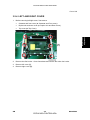
LSU (Laser Scanning Unit)
3.4 LSU (LASER SCANNING UNIT)
1.
Before removing the LSU, you should remove:
Top cover ( Top Cover).
Right cover ( Left and Right Cover)
2.
Remove four screws (M4 x 10).
3.
Disconnect the harness (one) from the main board [B].
4.
Remove the LSU [A].
M000/M009
3-8
CÓPIA NÃO CONTROLADA
SM
CÓPIA NÃO CONTROLADA
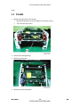
Drive
3.5 DRIVE
Before removing the drive, you should remove:
Top cover (Top Cover)
Left cover ( Left and Right Cover)
Replacement
Adjustment
1.
2.
Remove the seven screws indicated above.
3.
Disconnect the harness of the drive assembly.
4.
Drive [A]
SM
3-9
CÓPIA NÃO CONTROLADA
M000/M009
CÓPIA NÃO CONTROLADA
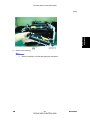
HVPS/SMPS/Main Board
3.6 HVPS/SMPS/MAIN BOARD
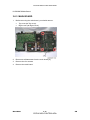
3.6.1 HVPS (HIGH VOLTAGE POWER SUPPLY)
1.
Before removing the HVPS, you should remove:
Top cover ( Top cover).
Right cover ( Left and Right cover).
2.
Remove the six screws indicated above.
3.
Disconnect the harness [B] at the back side of the HVPS [A].
4.
Remove HVPS.
5.
The Serial Number will be erased after replacing the main board.
Input the Serial Number ( Serial Number Input).
M000/M009
3-10
CÓPIA NÃO CONTROLADA
SM
CÓPIA NÃO CONTROLADA
HVPS/SMPS/Main Board
3.6.2 SMPS (SWITCHING MODE POWER SUPPLY)
Before removing the SMPS, you should remove:
Top cover ( Top cover).
Right cover ( Left and Right cover).
Replacement
Adjustment
1.
2.
Disconnect the three harnesses [A] from the SMPS [B].
3.
Remove the four screws.
4.
Remove the SMPS [B].
SM
3-11
CÓPIA NÃO CONTROLADA
M000/M009
CÓPIA NÃO CONTROLADA
HVPS/SMPS/Main Board
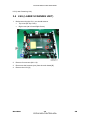
3.6.3 MAIN BOARD
1.
Before removing the main board, you should remove:
Top cover ( Top cover).
Right cover ( Right Cover).
2.
Disconnect all harnesses from the main board [A].
3.
Remove the four screws.
4.
Remove the main board.
M000/M009
3-12
CÓPIA NÃO CONTROLADA
SM
CÓPIA NÃO CONTROLADA
Pad-Holder
Replacement
Adjustment
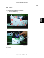
3.7 PAD-HOLDER
1.
Remove the cassette [A] from the printer.
2.
Release two hooks.
SM
3-13
CÓPIA NÃO CONTROLADA
M000/M009
CÓPIA NÃO CONTROLADA
Pad-Holder
3.
Release both of pivots [A] as shown above.
4.
Remove the pad-holder [B].
M000/M009
3-14
CÓPIA NÃO CONTROLADA
SM
CÓPIA NÃO CONTROLADA
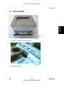
Transfer Roller
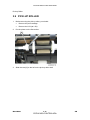
3.8 TRANSFER ROLLER
Open the front cover.
2.
Remove the print cartridge.
3.
Push the transfer holder [A], which holds the transfer roller [B].
4.
Remove the transfer roller from the printer.
Replacement
Adjustment
1.
SM
Do not directly touch the transfer roller when replacing it.
3-15
CÓPIA NÃO CONTROLADA
M000/M009
CÓPIA NÃO CONTROLADA
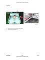
Pick-up Roller
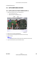
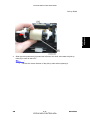
3.9 PICK-UP ROLLER
1.
Before removing the pick-up roller, you should:
Remove the print cartridge.
Remove the LSU ( LSU).
2.
Put the printer on the flat surface.
3.
Slide the cam [A] to the left on the pick up roller shaft.
M000/M009
3-16
CÓPIA NÃO CONTROLADA
SM
CÓPIA NÃO CONTROLADA
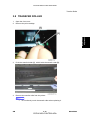
Replacement
Adjustment
Pick-up Roller
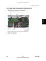
4.
Slide the roller positioners [A] toward the left end of the shaft, and rotate the pick-up
roller [B] in order to take off it.
SM
Confirm the correct direction of the pick-up roller when replacing it.
3-17
CÓPIA NÃO CONTROLADA
M000/M009
CÓPIA NÃO CONTROLADA
CÓPIA NÃO CONTROLADA
CÓPIA NÃO CONTROLADA
TROUBLESHOOTING
CÓPIA NÃO CONTROLADA
CÓPIA NÃO CONTROLADA
CÓPIA NÃO CONTROLADA
CÓPIA NÃO CONTROLADA
Procedure of Checking Symptoms
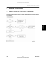
4. TROUBLESHOOTING
4.1 PROCEDURE OF CHECKING SYMPTOMS
Before attempting to repair the printer, first obtain a detailed description from the customer
Troubleshooting
of the problem.
SM
4-1
CÓPIA NÃO CONTROLADA
M000/M009
CÓPIA NÃO CONTROLADA
Symptoms, Causes, and Solutions of Bad Images
4.2 SYMPTOMS, CAUSES, AND SOLUTIONS OF BAD
IMAGES
4.2.1 VERTICAL BLACK LINE AND BAND
Description:
1.
Straight thin black vertical lines occur in the printing.
2.
Dark black vertical band occurs in the printing.
Symptom and Cause
1.
Deformed Doctor-blade or
cleaning-blade, in print cartridge
2.
1.
Partial depression or deformation on
and try to print.
2.
Replace the transfer roller if this occurs
as No. three.
the surface of the transfer roller.
M000/M009
If causes one or two occur in the print
cartridge, replace the print cartridge
Scratched surface of the charge roller
in the print cartridge.
3.
Solution
4-2
CÓPIA NÃO CONTROLADA
SM
CÓPIA NÃO CONTROLADA
Symptoms, Causes, and Solutions of Bad Images
4.2.2 VERTICAL WHITE LINE
Description:
White vertical voids in the image.
1.
Solution
Foreign matter stuck onto the window
1.
of internal lenses of LSU mirror.
2.
Clean the LSU window with
Foreign matter or toner particles
recommended cleaner (IPA) Clean the
between the print cartridge roller and
window with a clean cotton swab.
blade. (In case the life of the print
cartridge has expired, white lines or
light image may occur in front of the
2.
Replace the print cartridge.
3.
No 3: Remove the foreign matter and
burr of the exposure window. (print
image.)
3.
Burr and foreign substances are on the
window of the print cartridge frame.
4.
Foreign substances are on the OPC
Drum.
6.
cartridge)
4.
Partly depressed or deformed surface
the voids. Remove if found.
5.
If the problems are not solved, replace
the print cartridge.
6.
Replace the transfer roller if occurred
as No. 6
of the transfer roller
SM
No. 4: Open the front cover and check
ribs that correspond to the position of
If the fuser is defective, voids occur
periodically at the top of a black image.
5.
Foreign matter stuck onto the window:
4-3
CÓPIA NÃO CONTROLADA
M000/M009
Troubleshooting
Symptom and Cause
CÓPIA NÃO CONTROLADA
Symptoms, Causes, and Solutions of Bad Images
4.2.3 HORIZONTAL BLACK BAND
Description:
Dark or blurry horizontal stripes occur in the printing periodically. (They may not occur
periodically.)
Symptom and Cause
1.
2.
Solution
1.
Bad contacts of voltage terminals to
Clean each voltage terminal of the
print cartridge.
Charge, Supply, Develop and Transfer
The rollers of the print cartridge may be
roller. (Remove the toner particles and
stained.
paper particles.)
2.
Charge roller = 26.7mm
small gap of the teeth in the OPC.
Supply roller = 47.1mm
Develop roller = 35.2mm
3.
If the malfunction persists, replace the
print cartridge.
Transfer roller = 47mm
M000/M009
Clean the right Gear that has relatively
4-4
CÓPIA NÃO CONTROLADA
SM
CÓPIA NÃO CONTROLADA
Symptoms, Causes, and Solutions of Bad Images
4.2.4 BLACK/WHITE SPOT
1.
Dark or blurry black spots occur periodically in the printing.
2.
White spots occur periodically in the printing.
Symptom and Cause
Solution
1.
Run OPC cleaning Mode Print and run
the Self-test 2 or 3 times.
1.
2.
If dark or blurry black spots occur
irremovable in 1, cleanly remove
periodically, the rollers in the print
foreign substances stuck on the OPC
cartridge may be contaminated with
location equivalent to black spots and
foreign matter or paper particles.
white spots with a dry duster.
( Charge roller: 26.7 mm interval OPC
3.
drum: 75.5 mm interval)
2.
environment. If the roller's life is
image at intervals of 75.5 mm, or black
surface is probably damaged.
3.
expired, replace it.
4.
In case of 75.5 mm interval
irremovable in 1, take measures as to
If a black image is partially broken, the
replace the print cartridge and try to
transfer voltage is abnormal or the
transfer roller's life has expired.
The transfer roller guarantees 50.000
sheets printing in a normal
If faded areas or voids occur in a black
spots occur elsewhere, the OPC drum
In case of 75.5 mm interval
print out.
5.
Clean the inside of the set against the
paper particles and foreign matter in
order not to cause the problem.
SM
4-5
CÓPIA NÃO CONTROLADA
M000/M009
Troubleshooting
Description:
CÓPIA NÃO CONTROLADA
Symptoms, Causes, and Solutions of Bad Images
4.2.5 LIGHT IMAGE
Description:
The printed image is light, with no ghost.
Symptom and Cause
Solution
1.
1.
Check if the density light is lit.
Develop roller is stained when the print
cartridge toner is almost consumed.
2.
Ambient temperature is below 10°C.
3.
Bad contact caused by toner stains
2.
4.
3.
5.
No 2: Wait 30 minutes after printer is
powered on before you start printing.
4.
No3: Clean up the area contaminated
with toner.
Abnormal output from HVPS. (Run
self-test and check 1 to 4)
No 1: Replace the print cartridge and
try to print out.
between high voltage terminal in the
HVPS and the one in the set.
Check if the Toner Save mode is off.
5.
Replace the HVPS if the problems are
not solved by the above four
Check warranty out.
instructions.
M000/M009
4-6
CÓPIA NÃO CONTROLADA
SM
CÓPIA NÃO CONTROLADA
Symptoms, Causes, and Solutions of Bad Images
4.2.6 DARK IMAGE OR BLACK PAGE
Description:
The printed image is dark.
Solution
1.
Check the condition of the connector
1.
No charge voltage in the main board.
2.
Charge voltage is not turned on due to
which connects the main board and
bad contacts between power supply in
HVPS.
3.
the side of the print cartridge and
2.
Clean the high voltage charge terminal.
charge terminal of HVPS.
3.
Replace the HVPS if not solved by
state.
SM
step1 and 2 above.
VD0 signal of the main board is Low
4.
4-7
Replace the LSU Unit or Main Board.
CÓPIA NÃO CONTROLADA
M000/M009
Troubleshooting
Symptom and Cause
CÓPIA NÃO CONTROLADA
Symptoms, Causes, and Solutions of Bad Images
4.2.7 UNEVEN DENSITY
Description:
Print density is uneven between left and right.
Symptom and Cause
1.
Solution
The pressure force on the left and right
springs of the transfer roller is not
even; the springs are damaged; the
transfer roller is improperly installed; or
the transfer roller bushing or holder is
damaged.
2.
The life of the print cartridge has
1.
Holder.
2.
Gently shake the print cartridge.
3.
Replace the print cartridge and run
print test.
expired.
3.
Replace both the left and right Spring
The toner level is not even on the print
cartridge roller due to a bad blade.
M000/M009
4-8
CÓPIA NÃO CONTROLADA
SM
CÓPIA NÃO CONTROLADA
Symptoms, Causes, and Solutions of Bad Images
4.2.8 BACKGROUND
Description:
Light dark background appears across entire printed page.
Solution
1.
1.
designed to print 7,000 pages with 5%
Is the text less than 2% coverage per a
coverage. If it prints more than 8,000
page, and has the machine been out of
pages with 2% coverage, a
operation for a long time?
2.
Is a recycled print cartridge being
used?
3.
Has the life span of the print cartridge
expired?
4.
Is the movement (Up and Down) of the
transfer roller smooth?
5.
Is the HVPS normal?
The print cartridge is basically
background can occur.
2.
The A/S is not guaranteed if using a
recycled print cartridge.
3.
Replace the print cartridge when the
life span of it has expired.
4.
Clean the bushing part of the transfer
roller.
5.
If the problem is still not solved,
replace the print cartridge.
SM
4-9
CÓPIA NÃO CONTROLADA
M000/M009
Troubleshooting
Symptom and Cause
CÓPIA NÃO CONTROLADA
Symptoms, Causes, and Solutions of Bad Images
4.2.9 GHOST (1)
Description:
Ghost occurs at 75.5 mm intervals of the OPC drum across entire printed page.
Symptom and Cause
1.
Solution
Bad contacts caused by contamination
from toner particles between the high
1.
voltage terminal in the main body and
contaminated by toner particles.
the electrode of the print cartridge.
2.
Bad contacts caused by contamination
from toner particles between high
voltage terminal of the main body and
the one in the HVPS board.
3.
The life of print cartridge has expired.
4.
Transfer roller lifetime (50,000 sheets)
has been exceeded.
5.
Abnormal, low temperature (below
10°C).
6.
Clean the terminals when
2.
For the print cartridge, replace the print
cartridge and try to print out.
3.
Replace the main board if not solved
by steps 1 and 2 above.
4.
If not solved by the step 3, check the
transfer roller lifetime and replace it.
5.
Wait about 1 hour after power on
before using printer.
6.
For the print cartridge, replace the print
cartridge and try to print out.
Damaged cleaning blade in the print
cartridge.
M000/M009
4-10
CÓPIA NÃO CONTROLADA
SM
CÓPIA NÃO CONTROLADA
Symptoms, Causes, and Solutions of Bad Images
4.2.10 GHOST (2)
Description:
Ghost occurs at 75.5 mm intervals of the OPC drum on all pages of print jobs. (When
printing on card stock or transparencies using manual feeder)
Solution
Select Card stock or OHP Film on paper
When printing on card stock thicker than
type menu from the software application
normal paper or transparencies such as
setting. After using, it is recommended that
OHP, higher transfer voltage is required.
the mode should be returned to the original
setting.
SM
4-11
CÓPIA NÃO CONTROLADA
M000/M009
Troubleshooting
Symptom and Cause
CÓPIA NÃO CONTROLADA
Symptoms, Causes, and Solutions of Bad Images
4.2.11 GHOST (3): FUSER
Description:
Ghost occurs at 62.8 mm or 77.6mm intervals.
Symptom and Cause
Solution
Disassemble the fuser and remove the
The temperature of the fuser is maintained
at a high temperature.
contaminated toner particles on the roller,
and clean out the foreign matter between
the thermistor and heat roller.
(Caution: can be deformed)
M000/M009
4-12
CÓPIA NÃO CONTROLADA
SM
CÓPIA NÃO CONTROLADA
Symptoms, Causes, and Solutions of Bad Images
4.2.12 STAINS ON THE FACE OF PAGE
Description:
The background on the face of the printed page is stained.
1.
Solution
Toner leakage due to improperly
sealed print cartridge.
2.
1.
Replace the print cartridge.
2.
If the transfer roller is contaminated,
run OPC Cleaning Mode Print 2 or 3
If the transfer roller is contaminated,
stains on the face of a page may occur.
SM
4-13
times. And perform Self-Test 2 or 3
times to remove contamination.
CÓPIA NÃO CONTROLADA
M000/M009
Troubleshooting
Symptom and Cause
CÓPIA NÃO CONTROLADA
Symptoms, Causes, and Solutions of Bad Images
4.2.13 STAINS ON THE BACK OF PAGE
Description:
The back of the page is stained at 47 or 62.8 mm intervals.
Symptom and Cause
Solution
1.
Perform the OPC Cleaning Mode Print
2 or 3 times. Run self-test to remove
the contamination of the transfer roller.
2.
1.
47mm: Transfer roller is contaminated.
2.
62.8mm: Pressure roller is
Replace the transfer roller if
contaminated severely.
3.
Disassemble the fuser and clean the
H/R (Heat Roller) and P/R (Pressure
contaminated.
Roller). Also check the area between
H/R and Thermistor. If contaminated,
clean the area, taking caution not to
cause deformation of roller.
M000/M009
4-14
CÓPIA NÃO CONTROLADA
SM
CÓPIA NÃO CONTROLADA
Symptoms, Causes, and Solutions of Bad Images
4.2.14 BLANK PAGE PRINT OUT (1)
Description:
Blank page is printed.
Solution
1.
Bad ground contacts in OPC and/or print
cartridge.
Check if the Ground-OPC is defective
(set inside left side).
2.
Remove contamination from the
terminals of the print cartridge and the
unit.
SM
4-15
CÓPIA NÃO CONTROLADA
M000/M009
Troubleshooting
Symptom and Cause
CÓPIA NÃO CONTROLADA
Symptoms, Causes, and Solutions of Bad Images
4.2.15 BLANK PAGE PRINT OUT (2)
Description:
1.
Blank page is printed.
2.
One or several blank pages are printed.
3.
When the printer turns on, several blank pages print.
Symptom and Cause
Solution
1.
Remove contamination of the terminals
of the print cartridge.
2.
1.
2.
Perform the engine self test using EDC
Bad ground contacts in OPC and/or
Mode to check if the Solenoid is
print cartridge.
normal.
Abnormal solenoid.
3.
If not solved by steps 1 and 2 above,
replace the engine board.
4.
Turn the power off, delete print data
from PC and try printing again.
M000/M009
4-16
CÓPIA NÃO CONTROLADA
SM
CÓPIA NÃO CONTROLADA
Discharge Symptoms, Causes, and Solutions
4.3 DISCHARGE SYMPTOMS, CAUSES, AND
SOLUTIONS
4.3.1 WRONG PRINT POSITION
Description:
Printing begins at the wrong position on the paper.
Symptom and Cause
Wrong sensing time caused by defective
Replace the defective feed sensor actuator.
Troubleshooting
feed sensor actuator.
Solution
SM
4-17
CÓPIA NÃO CONTROLADA
M000/M009
CÓPIA NÃO CONTROLADA
Discharge Symptoms, Causes, and Solutions
4.3.2 JAM 0
Description:
1.
Paper does not exit the cassette.
2.
Jam-0 occurs if the paper feeds into the printer.
Symptom and Cause
1.
Solution
Check the solenoid by using EDC
Mode.
2.
Check if the pad is loose due to bad
sealing of the side-pad.
3.
4.
Check the surface of the roller-pickup
1.
Replace the solenoid.
for foreign matter.
2.
Replace the side-pad Assembly L or R,
if necessary.
If continuous clusters occur, check
3.
whether the assembly slot between
IPA (Isopropyl Alcohol) or water.
shaft-pickup and housing-pickup opens
4.
or is broken away.
5.
Clean with soft cloth dampened with
Replace the main board and/or Sensor.
If the paper feeds into the printer and
Jam 0 occurs, perform EDC Mode to
check the feed-sensor of the main
board.
M000/M009
4-18
CÓPIA NÃO CONTROLADA
SM
CÓPIA NÃO CONTROLADA
Discharge Symptoms, Causes, and Solutions
4.3.3 JAM 1
Description:
1.
Recording paper is jammed in front of or inside the fuser.
2.
Recording paper is stuck in the discharge roller and in the fuser just after passing
Symptom and Cause
1.
Solution
If paper is jammed in front of or inside
the fuser.
2.
If the recording paper is stuck in the
discharge roller and the fuser just after
1.
Replace the SMPS or Exit-Sensor.
2.
Replace the main board.
3.
Reassemble the Actuator-Feed and
passing through the Actuator-Feed,
bad.
Feed Actuator may be defective.
SM
Spring-Actuator if the movement is
4-19
CÓPIA NÃO CONTROLADA
M000/M009
Troubleshooting
through the Actuator-Feed.
CÓPIA NÃO CONTROLADA
Discharge Symptoms, Causes, and Solutions
4.3.4 JAM 2
Description:
1.
Recording paper is jammed in front of or inside the fuser.
2.
Recording paper is stuck in the discharge roller and in the fuser just after passing
through the Actuator-Feed.
Symptom and Cause
1.
Solution
If the paper is completely fed out of the 1.
Check if the exit sensor actuator is
printer, but Jam 2 occurs: Exit sensor is
defective.
defective.
After the paper is completely
deformed (Check if the lever part is
discharged, actuator Exit should
deformed).
return to the original position to
2.
Check whether burrs occur in the
shut the photo-sensor. Sometimes
assembly part of the actuator exit
it takes longer than it should and
or not and if the actuator is
does not return.
smoothly operated.
If the paper is rolled in the Fuser Roller:
Check if the actuator exit is
Check if foreign matter and wire
This occurs when a Guide claw is
get caught in the actuator exit's
broken away or transformed.
operation.
It occurs when the Spring of a
2.
If the paper is stuck in the fuser:
Guide claw is broken away or
disassemble the fuser and remove the
transformed.
jammed paper, and clean the surface
It occurs when the Heat-Roller or
of the pressure roller with dry gauze.
Pressure-Roller is seriously
3.
Remove the jammed paper after
disassembling the fuser: Clean the
contaminated with the toner.
surface of the pressure roller with dry
M000/M009
4-20
CÓPIA NÃO CONTROLADA
SM
CÓPIA NÃO CONTROLADA
Discharge Symptoms, Causes, and Solutions
3.
Paper is accordion in the fuser.
gauze.
Remove the toner particles stained
on the rib.
Check the assemblage and
performance of the exit.
Troubleshooting
4.3.5 DUPLEX JAM
Description:
Recording paper is Jammed in front or inside the duplex
Symptom and Cause
1.
2.
Solution
When paper cannot trigger the duplex
1.
Replace the SMPS or main PBA
2.
When a paper jam occurs on (A) after it
sensor.
is reversed: replace the 2nd exit roller
When paper cannot reach the duplex
after checking its operation.
sensor due to a paper jam on a duplex
3.
When a paper jam occurs on (B) after it
is reversed: replace the duplex roller
path.
after checking its operation
SM
4-21
CÓPIA NÃO CONTROLADA
M000/M009
CÓPIA NÃO CONTROLADA
Discharge Symptoms, Causes, and Solutions
4.3.6 MULTI-FEEDING
Description:
Multiple sheets of paper are fed at once.
Symptom and Cause
1.
Solution
Check the Guide side L/R or Guide
Rear in the Cassette, if the position is
2.
correct.
1.
Replace the solenoid if necessary.
Solenoid malfunction (the solenoid
2.
Replace the main board.
does not work properly): Perform EDC
3.
Clean the pad friction with soft cloth
dampened with IPA (Isopropyl Alcohol).
Mode.
3.
Pad-Friction is contaminated with
4.
Use smooth paper.
foreign matter. (oil...)
4.
The face of the paper is bent.
M000/M009
4-22
CÓPIA NÃO CONTROLADA
SM
CÓPIA NÃO CONTROLADA
Discharge Symptoms, Causes, and Solutions
4.3.7 PAPER ROLLED IN THE FUSER
Description:
If contaminated at intervals of 77.6mm on the back of the paper.
Symptom and Cause
Solution
1.
After disassembling the fuser, clean
contamination between the heat roller
and the thermistor and remove the
contamination of the pressure roller.
2.
Contamination of the pressure roller or
2.
If there is a heavy background, repair it
heat roller (Background, Hot off set).
with the background troubleshooting
Check the claws of the fuser for
method.
deformities.
3.
Clean the surface of the heat roller with
IPA or water
4.
Check the warp or separation of the
print claw and the holder plate claw,
and then manage it.
SM
4-23
CÓPIA NÃO CONTROLADA
M000/M009
Troubleshooting
1.
CÓPIA NÃO CONTROLADA
Discharge Symptoms, Causes, and Solutions
4.3.8 PAPER ROLLED ON THE OPC DRUM
Description:
Paper is rolled up in the OPC.
Symptom and Cause
Solution
1.
Use of normal paper is recommended.
2.
How to remove rolled paper from the
OPC.
1.
Paper is too thin.
2.
The paper is curled.
Remove the paper while turning
the OPC against the ongoing
direction.
Clean fingerprints on the OPC
gently with damp soft cloth.
M000/M009
4-24
CÓPIA NÃO CONTROLADA
SM
CÓPIA NÃO CONTROLADA
Malfunction Causes and Solutions
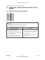
4.4 MALFUNCTION CAUSES AND SOLUTIONS
4.4.1 FUSER ERROR
Description:
All LEDs are blinking
Check...
Check whether thermostat, AC wire,
1.
open.
and heat lamp are open or not.
2.
Check whether thermistor is open or
Replace the fuser if the thermostat is
2.
Replace the fuser if a thermistor sensor
is located deep inside of a sponge.
not.
3.
3.
Heat lamp ON/OFF test
4.
Operation is impossible due to a gear
circuit is operating normally or not.
4.
of a fuser being melted.
Check whether the overheat mode
Replace the fuser.
4.4.2 LSU (LASER SCANNING UNIT) ERROR
Description:
“PMOTOR ERROR/HSYNC ERROR”
Check...
1.
2.
3.
SM
Solutions
Check whether the LSU (Laser
Scanning Unit) connector is
1.
Replace the LSU.
disconnected or not.
2.
Replace the main board if the same
Check whether the LSU motor is
error occurs again after replacing the
rotating or not.
LSU.
Check the HSYNC signal.
4-25
CÓPIA NÃO CONTROLADA
M000/M009
Troubleshooting
1.
Solutions
CÓPIA NÃO CONTROLADA
Malfunction Causes and Solutions
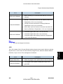
4.4.3 MALFUNCTION OF THE GEAR OF THE FUSER DUE TO
MELTING
Description:
The motor breaks away from its place due to gear melting away.
Check...
Solutions
Check the Heat lamp.
1.
Replace the Fuser.
2.
Replace the main board.
3.
Replace the SMPS.
4.4.4 PAPER EMPTY
Description:
The status LED on the operation panel is on even when paper is loaded in the cassette.
Check...
1.
Solutions
Bending or deformation of the actuator
of the paper sensor.
1.
Replace the defective actuator.
2.
The main board is defective
2.
Replace the empty sensor main board.
3.
Check the connector.
M000/M009
4-26
CÓPIA NÃO CONTROLADA
SM
CÓPIA NÃO CONTROLADA
Malfunction Causes and Solutions
4.4.5 PAPER EMPTY WITHOUT INDICATION
Description:
The paper lamp on the operation panel does not come on when the paper cassette is
empty.
Check...
1.
Solutions
Bending or deformation of the actuator
of the paper sensor.
2.
The main board is defective.
1.
Replace the defective actuator.
2.
Replace the defective board.
Troubleshooting
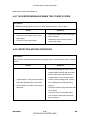
4.4.6 COVER OPEN
Description:
The ERROR lamp is on even when the print cover is closed.
Check...
1.
Solutions
The hook lever in the top cover may be
defective.
2.
Check connectors and the cover switch
department in the main board.
SM
1.
Replace the hook lever, if defective.
2.
Check the insertion of the cover-open
S/W connector.
3.
Replace the main board or cover open
S/W.
4-27
CÓPIA NÃO CONTROLADA
M000/M009
CÓPIA NÃO CONTROLADA
Malfunction Causes and Solutions
4.4.7 NO ERROR MESSAGE WHEN THE COVER IS OPEN
Description:
An ERROR message does not come on even when the printer cover is open
Check...
1.
Solutions
1.
Check the cover-open circuit on the
S/W connector.
main board.
2.
Check the insertion of the cover-open
2.
Check the cover-open board.
Replace the main control board or
cover-open board.
4.4.8 DEFECTIVE MOTOR OPERATION
Description:
Main motor is not driving when printing, and paper does not feed into the printer, resulting
'Jam 0'.
Check...
Solutions
1.
After disassembling the fuser, clean
contamination between the heat roller
and the thermistor and remove any
contamination on the pressure roller.
1.
2.
Contamination of the pressure roller or
2.
If there is heavy background, repair it
heat roller (Background, Hot off set)
by the background troubleshooting
Check whether the claw of the fuser is
method.
deformed.
3.
Clean the surface of the heat roller with
IPA or water.
4.
Check the warp or the holder plate
claw and the holder plate clew, and
then manage it.
M000/M009
4-28
CÓPIA NÃO CONTROLADA
SM
CÓPIA NÃO CONTROLADA
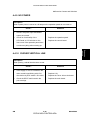
Malfunction Causes and Solutions
4.4.9 NO POWER
Description:
When system power is turned on, all lamps on the operation panel do not come on.
Check...
1.
Solutions
Check if the power input and SMPS
output are normal.
2.
Check for functionality of the
1.
Replace the operation panel.
LED-Panel or LCD window on the
2.
Replace the control board.
front-cover if the operation panel does
Troubleshooting
not show anything after warming-up.
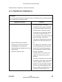
4.4.10 CURVED VERTICAL LINE
Description:
When printing, vertical lines become curved.
Check...
1.
Solutions
If the supply of +24v is unstable in the
main control board linking with LSU,
1.
check drive by EDC mode: LSU check. 2.
2.
Check the DEVE main board in the
3.
Replace LSU.
Replace the Toner Joint main board.
Replace the main board.
print cartridge.
SM
4-29
CÓPIA NÃO CONTROLADA
M000/M009
CÓPIA NÃO CONTROLADA
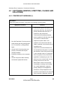
Software (Errors, Symptoms, Causes and Solutions)
4.5 SOFTWARE (ERRORS, SYMPTOMS, CAUSES AND
SOLUTIONS)
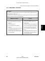
4.5.1 PRINTER NOT WORKING (1)
Description:
When main power is turned on, the printer is not working in printing mode.
Symptom and Cause
Solution
1.
Check that the printer has power, and
perform the Self-Test. Successful test
printing indicates that there are no
problems in the printer itself.
Unsuccessful test printing indicates
that the problem is with the printer, and
is not due to a software issue.
1.
Run Self-Test Mode: Turn the power on
2.
problem is not solved even after the
while pressing the test printing button
cable is replaced, check the amount of
for 2 or 3 seconds - printing should
begin.
2.
Check if the PC and the printer are
remaining toner.
3.
MS-Windows, check if the printer driver
cartridge installed.
in the controller is set up. If the printer
Printing not working on the computer
driver is properly set up, check which
side.
4.
Check if the connection between the
PC and printer port is proper. If you use
properly connected and the print
3.
Replace the printer cable. If the
application is attempting to print. The
Check if the printer cable is directly
best way to run a quick check, is to try
connected to peripheral devices.
printing a few lines of text from
Memo-Pad in order to check printer
functionality. If printing is not working
for a certain application, adjust the
printing settings for that application.
Sometimes a simple adjustment will
produce a normal printout, but may still
fail to work with a particular software
M000/M009
4-30
CÓPIA NÃO CONTROLADA
SM
CÓPIA NÃO CONTROLADA
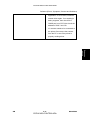
Software (Errors, Symptoms, Causes and Solutions)
application. In such cases, install the
newest driver again. If not working in
basic programs, then check if the
CMOS port is on ECP. Also check the
address of IRQ 7 and 378.
4.
If a scanner needs to be connected to
the printer, first remove the scanner
from the PC to see if the printer is
Troubleshooting
properly working alone.
SM
4-31
CÓPIA NÃO CONTROLADA
M000/M009
CÓPIA NÃO CONTROLADA
Software (Errors, Symptoms, Causes and Solutions)
4.5.2 PRINTER NOT WORKING (2)
Description:
After receiving a printing order, response is slow or nonexistent due to wrong setup rather
than a malfunction of the printer itself.
Symptom and Cause
Solution
1.
Not working with the message
'insufficient printer memory' indicates
an HDD space problem rather than a
RAM problem. In this case, provide
more space on the hard disk. Secure
more space using disk utilities, etc.
2.
The connection of the cable and printer
port is not proper. Check if the
connection is properly done and if the
parallel port in CMOS is properly set
1.
More hard disk space necessary.
2.
Printing error occurs even if there is
3.
4.
up.
3.
As a printer port, Select ECP or SPP
enough space on the hard disk.
out of SPP (Normal), ECP, and EPP
Check parallel-port-related items in the
modes. SPP normal mode supports
CMOS Setup.
8-bit data transfer, while ECP Mode
Reboot the system to print.
transfers 12-bit data.
4.
If regular fonts are not printing, the
cable or the printer driver may be
defective.
5.
Turn the PC and printer off, and reboot
the system to print again. If this doesn't
solve the problem, double-click the
printer icon in My Computer If regular
fonts are not printed taking this step,
then the cable may be defective, so try
replacing the cable with new one.
M000/M009
4-32
CÓPIA NÃO CONTROLADA
SM
CÓPIA NÃO CONTROLADA
Software (Errors, Symptoms, Causes and Solutions)
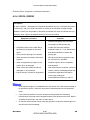
4.5.3 ABNORMAL PRINTING
Description:
The printer is not working properly even when the cable has been verified to be good
(after replacing the cable, etc.).
If the printer won't work at all or the strange fonts are repeated, the printer driver may be
defective or wrongly set up in the CMOS Setup.
Symptom and Cause
Solution
1.
Select SPP (Normal) or ECP LPT Port
Set up the parallel port in the CMOS
(among ECP, EPP or SPP) in the
SETUP.
CMOS Setup.
2.
Check the printer in My Computer. (To
2.
Printer Driver Error.
3.
Error message from insufficient
see if the printer driver is compatible
memory.
with the present driver. Delete old
(The printing job sometimes stops due
driver, if defective, and reinstall new
to insufficient virtual memory, but it
one.)
4.
actually comes from insufficient space
3.
Delete unnecessary files to open up
enough space of the hard disk and
on the hard disk.)
start printing job again.
SM
4-33
CÓPIA NÃO CONTROLADA
M000/M009
Troubleshooting
1.
CÓPIA NÃO CONTROLADA
Software (Errors, Symptoms, Causes and Solutions)
4.5.4 SPOOL ERROR
Description:
To spool: (SPOOL - Simultaneous Peripheral Operations OnLine" a computer document
or task list (or "job") is to read it and store it, usually on a hard disk or larger storage
medium so that it can be printed or otherwise processed at a more convenient time (for
example, when a printer is finished printing its current document).
Symptom and Cause
Solution
1.
Delete unnecessary files to provide
more space to start printing job.
1.
2.
Insufficient space on the hard disk in
If there are some files with the
the directory assigned for the basic
extension name of ****.jnl, delete them
spool.
and reboot Windows to restart the
2.
If the previous printing error remains.
printing job.
3.
When expected to interfere with other
3.
the current one, if possible.
program.
4.
4.
When an application program or the
5.
When some files related to OS are
6.
Delete the printer driver completely
and reinstall it.
printer driver is damaged.
5.
Shut down all other programs except
After rebooting the computer, check for
damaged or virus infected.
viruses, restore the damaged files and
Actual memory is less than suggested.
reinstall the application that will be
running the printing job.
6.
Install additional memory in the PC.
In the spool manager, the installed drivers and the list of the documents waiting to
be printed are shown. Select the document to be deleted and check the delete
menu.
If you intend to delete the current document being printed, the data being
transferred to the printer will be stopped and then the document removed. Before
choosing the document, the menu is still inactive.
Or remove the document from the list and repeat the routine as outlined above or
else finish the spool manager.
M000/M009
4-34
CÓPIA NÃO CONTROLADA
SM
CÓPIA NÃO CONTROLADA
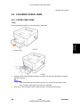
Clearing Paper Jams
4.6 CLEARING PAPER JAMS
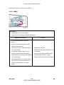
4.6.1 PAPER FEED AREA
Tray 1
Troubleshooting
Do the following procedure to solve this type of paper jam.
1.
Pull the tray 1.
2.
Carefully pull the jammed paper straight out. Make sue that all of the paper is properly
aligned in the tray 1.
If the paper does not move when you pull, or if you do not see paper in this
area, check the fuser area around the print cartridge.
3.
SM
Insert tray 1 into the printer until it snaps into place. Printing should resume.
4-35
CÓPIA NÃO CONTROLADA
M000/M009
CÓPIA NÃO CONTROLADA
Clearing Paper Jams
Optional tray 2
Do the following procedure to solve this type of paper jam.
1.
Pull open the optional paper tray 2.
1.
Remove the jammed paper from the printer. Do not continue if the paper does not
move or if you do not see the paper in this area. In this case, go to the next step.
2.
Pull the tray 1 halfway out.
3.
Pull the paper straight up and out.
4.
Insert tray 1 and tray 2 back into the printer. Printing should resume.
M000/M009
4-36
CÓPIA NÃO CONTROLADA
SM
CÓPIA NÃO CONTROLADA
Clearing Paper Jams
In the manual tray
Do the following procedure to solve this type of paper jam.
Remove the jammed paper from the printer.
2.
Open and close the front cover.
3.
Load a sheet of paper into the manual feeder. Printing should resume.
Troubleshooting
1.
SM
4-37
CÓPIA NÃO CONTROLADA
M000/M009
CÓPIA NÃO CONTROLADA
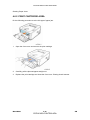
Clearing Paper Jams
4.6.2 PRINT CARTRIDGE AREA
Do the following procedure to solve this type of paper jam.
1.
Open the front cover and remove the print cartridge.
2.
Carefully pull the jammed paper straight out.
3.
Replace the print cartridge and close the front cover. Printing should resume.
M000/M009
4-38
CÓPIA NÃO CONTROLADA
SM
CÓPIA NÃO CONTROLADA
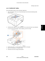
Clearing Paper Jams
4.6.3 PAPER EXIT AREA
Do the following procedure to solve this type of paper jam.
1.
Open and close the front cover. The jammed paper should be automatically ejected
2.
Carefully pull the paper out of the output tray. Do not continue if there is any resistance
or if you do not see the paper. In this condition, go to the next step.
3.
Pull the rear guide { on each side down, and remove the paper.
4.
Return the rear guide to its original position.
5.
Close the rear cover. Printing should resume.
SM
4-39
CÓPIA NÃO CONTROLADA
M000/M009
Troubleshooting
from the printer.
CÓPIA NÃO CONTROLADA
Clearing Paper Jams
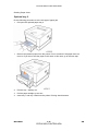
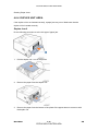
4.6.4 DUPLEX UNIT AREA
If the duplex unit is not inserted correctly, a paper jam may occur. Make sure that the
duplex unit is inserted correctly.
Duplex Jam 0
Do the following procedure to solve this type of paper jam.
1.
Pull the duplex unit { out of the printer.
2.
Remove the paper from the duplex unit.
3.
Remove the paper from the bottom of the printer if the paper does not come out with
the duplex unit.
M000/M009
4-40
CÓPIA NÃO CONTROLADA
SM
CÓPIA NÃO CONTROLADA
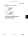
Clearing Paper Jams
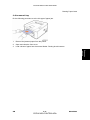
Duplex Jam 1
1.
Open the rear cover.
2.
Pull the rear guide { on each side down and remove the paper.
3.
Return the rear guide to its original position.
4.
Close the rear cover. Printing should resume.
SM
4-41
CÓPIA NÃO CONTROLADA
Troubleshooting
Do the following procedure to solve this type of paper jam.
M000/M009
CÓPIA NÃO CONTROLADA
Clearing Paper Jams
4.6.5 TIPS TO AVOID PAPER JAMS
Do the following procedure to reduce paper jam occurrences.
Make sure that the adjustable guides are positioned correctly.
Ensure that the paper is below the paper capacity mark on the right inside of the tray.
Do not remove the paper from the tray at the time the machine prints.
Flex, fan and straighten the paper before you load it into the paper feed unit.
Do not use creased, dropped or highly curled paper.
Do not mix paper types.
Use only recommended print media.
Ensure that the recommended print side of print media is facing down when you load
paper to the input tray, or facing up in the bypass tray.
If paper jams occur frequently when you print on A5-sized paper, then load the paper
into the tray with the long edge facing the front of the tray as shown below.
M000/M009
4-42
CÓPIA NÃO CONTROLADA
SM
CÓPIA NÃO CONTROLADA
Periodic Defective Image
4.7 PERIODIC DEFECTIVE IMAGE
If defective images regularly occur in print-outs, it may be due to a defective or damaged
roller.
Refer to the table below and check the condition of the roller.
Roller
Defective image
Typical defect
1
OPC Drum
75.5 mm
White spots, black spots
2
Charge Roller
26.7 mm
Black spots and periodic bands
3
Supply Roller
47.1 mm
4
Developing Roller
35.2 mm
5
Transfer Roller
6
Heat Roller
77.6 mm
Black spots or vertical black bands
7
Pressure Roller_1st
62.8 mm
Black background
8
Pressure Roller_2st
37.7 mm
Black background
SM
47 mm
4-43
Periodic bands with slight
differences in density
White spots, horizontal black bands
Ghosting, damaged image due to
abnormal transfer
CÓPIA NÃO CONTROLADA
M000/M009
Troubleshooting
No
CÓPIA NÃO CONTROLADA
CÓPIA NÃO CONTROLADA
CÓPIA NÃO CONTROLADA
SERVICE TABLES
CÓPIA NÃO CONTROLADA
CÓPIA NÃO CONTROLADA
CÓPIA NÃO CONTROLADA
CÓPIA NÃO CONTROLADA
Firmware Download
5. SERVICE TABLES
5.1 FIRMWARE DOWNLOAD
5.1.1 DOWNLOAD PROCEDURE
There are two ways to upgrade the machine firmware.
1.
Command Prompt
2.
WIM (Web Image Monitor)
Connect the machine to a PC with the USB “Command Prompt” or through the network for
“WIM” before you do the firmware upgrade procedure.
It is very rare to lose data and settings after the program has downloaded. However you
should print out the Configuration page list before you start the download procedure.
DOS Command Mode
Program (firmware) for this machine can be upgraded by connecting to a PC via a USB
cable. A Command to upgrade the program must be entered.
1.
Print out the Configuration page for back up the data and setting.
2.
Download the "usblist2.exe" file and “firmware file” to the PC.
3.
Connect the PC and the machine with a USB cable.
4.
Turn on the main power of the machine.
5.
Open the DOS command window.
6.
Enter the directly where you have already downloaded the firmware.
SM
5-1
CÓPIA NÃO CONTROLADA
Service
Tables
You must save the correct firmware file to the PC.
M000/M009
CÓPIA NÃO CONTROLADA
Firmware Download
7.
Run the "usblist2.exe" and “firmware file”.
In Command prompt, type " usblist2.exe XXX" and press enter key. XXX indicates
the firmware name as shown above.
Do not turn off the machine during the firmware upgrading.
WIM (Web Image Monitor) mode
Program (firmware) for this machine can be upgraded by connecting to a PC through
Network.You must save the correct firmware file to the PC.
1.
Print out the Configuration page for back up the data and setting.
2.
Download the Firmware on the PC.
3.
Access the “WIM” with the correct IP address.
4.
Select "Maintenance" [A] as shown above.
5.
Make sure that "Firmware Upgrade" [B] is selected as shown above. If not, select it.
6.
Click the "Browse" button [C] and select the Printer Firmware file you have saved in the
PC.
M000/M009
5-2
CÓPIA NÃO CONTROLADA
SM
CÓPIA NÃO CONTROLADA
7.
Click the "Upgrade" button [D].
8.
Press "OK" button.
9.
Press "OK" button to start processing upgrade.
Service
Tables
Firmware Download
10. Make sure that the firmware has been completely updated.
Do not turn off the power while updating the Firmware.
5.1.2 FIRMWARE RECOVERY PROCEDURE
The machine will not operate if the upgrade procedure did not work correctly. At this time,
do the following steps.
1.
Turn the power off and then on.
2.
Do the steps in the above download procedure.
The machine will start the upgrade again.
SM
5-3
CÓPIA NÃO CONTROLADA
M000/M009
CÓPIA NÃO CONTROLADA
Serial Number Input
5.2 SERIAL NUMBER INPUT
You must specify a Serial Number after you replace the main board.
5.2.1 PREPARATION
1.
Print out the “Configuration page” for back up the data and the setting.
2.
Download the “Write USB Serial” file in the PC.
3.
Reboot the PC.
5.2.2 PROCEDURE
1.
Click the “Write USB Serial”.
2.
Input the Serial Number.
3.
Click the “Write”.
M000/M009
5-4
CÓPIA NÃO CONTROLADA
SM
CÓPIA NÃO CONTROLADA
Serial Number Input
Confirm the message “Writing Good!” is shown.
5.
Click the “OK”, and then close the window.
6.
Print out the “Configuration page” and confirm the Serial Number is input.
Service
Tables
4.
SM
5-5
CÓPIA NÃO CONTROLADA
M000/M009
CÓPIA NÃO CONTROLADA
Sample Pattern
5.3 SAMPLE PATTERN
This product has several sample patterns for maintenance. With the sample patterns,
check the existence of any abnormalities. The patterns help to regularly maintain the
product.
5.3.1 DEMO PAGE
After setting up the printer, print a demo page to make sure that the printer is operating
correctly.
1.
Press the “Cancel” button for two seconds.
2.
A demo page is printed out.
M000/M009
5-6
CÓPIA NÃO CONTROLADA
SM
CÓPIA NÃO CONTROLADA
Sample Pattern
5.3.2 CONFIGURATION PAGE
1.
Press the “Cancel” button for four seconds.
2.
A configuration page is printed out.
The “Menu Map” page is printed out with a configuration page.
Service
Tables
SM
5-7
CÓPIA NÃO CONTROLADA
M000/M009
CÓPIA NÃO CONTROLADA
Sample Pattern
M000/M009
5-8
CÓPIA NÃO CONTROLADA
SM
CÓPIA NÃO CONTROLADA
DETAILED DESCRIPTIONS
CÓPIA NÃO CONTROLADA
CÓPIA NÃO CONTROLADA
CÓPIA NÃO CONTROLADA
CÓPIA NÃO CONTROLADA
Overview
6. DETAILED DESCRIPTIONS
6.1 OVERVIEW
This chapter describes the main functions for service, such as the product maintenance
method, the test output related to maintenance and repair, Jam removing method, etc.
6.1.1 KEY OPERATION
[A]
Error: Indicates the status of the printer.
[B]
Online: Indicates whether the printer is online.
[C]
SM
Prints a demo page or configuration page (press and hold for three seconds).
Cancels the print job.
Causes the printer to feed.
6-1
CÓPIA NÃO CONTROLADA
M000/M009
Detailed
Descriptions
Cancel:
CÓPIA NÃO CONTROLADA
Overview
6.1.2 LED STATUS ERROR MESSAGE
1.
The cover is open.
2.
No paper in the tray
On
Load paper in the tray.
3.
The printer has stopped printing due to a major error.
4.
The print cartridge is not installed.
5.
Red
Close the cover.
Error
The life of the print cartridge.
1.
Install the print cartridge.
Replace the print cartridge.
A minor error is occurring and the printer is waiting for
the error to be cleared.
Blinking
printing.
2.
The print cartridge is near end.
Orange
On
On
Replace a new print cartridge.
1.
A paper jam has occurred.
1.
The printer is in the power save mode.
2.
The printer is on-line and can receive data from the
computer.
Online Green
1.
Blinking
Blinks slowly indicates that the printer is receiving
data from the computer.
2.
M000/M009
When the problem is cleared, the printer resumes
Blinks quickly indicates that the printer is printing data.
6-2
CÓPIA NÃO CONTROLADA
SM
CÓPIA NÃO CONTROLADA
Printer Components
6.2 PRINTER COMPONENTS
Detailed
Descriptions
6.2.1 FRONT VIEW
1. Output tray
6. Tray 1
2. Control panel
7. Optional tray 2
3. Control board cover
8. Paper level indicator
4. Front cover
9. Out put support
5. By-Pass tray
10.By-pass tray paper width guides
SM
6-3
CÓPIA NÃO CONTROLADA
M000/M009
CÓPIA NÃO CONTROLADA
Printer Components
6.2.2 REAR VIEW
1. Network port (Only for M009)
4. Duplex unit
2. USB port
5. Power receptacle
3. Optional tray 2 cable connector
6. Power switch
M000/M009
6-4
CÓPIA NÃO CONTROLADA
SM
CÓPIA NÃO CONTROLADA
System Layout
6.3 SYSTEM LAYOUT
6.3.1 FEEDING
Paper feeding consists of a basic cassette, an MP (Multi-Purpose) tray for supplying
different types of media (envelopes, labels, and special paper), duplex unit, and various
paper transfer parts.
Separation method
Separation is achieved by a friction pad mounted in the center of the cassette.
Basic cassette
upon first sheet size detected by printer controller. Both the side guide and the rear guide
can be adjusted for various types of paper from A5 to legal size paper. Paper sensing;
(capacity: 250 sheets of general paper); paper arranging; Paper Feed Unit paper path; and
remaining paper display functions. Remaining paper indicator located on front of machine
on right side of paper drawer.
Pick-up roller
Paper pickup; driving control, paper feeding; and electronic static removal.
Registration roller
Paper arranging; paper transferring; paper detecting; jam removal, and other functions.
SM
6-5
CÓPIA NÃO CONTROLADA
M000/M009
Detailed
Descriptions
Center loading method utilized with friction pad separation. Paper size detection based
CÓPIA NÃO CONTROLADA
System Layout
By-pass tray
Paper arranging; paper transferring; jam removal; and other functions. Rubbing pad
method enabling feed of one sheet of general paper or one envelop.
Duplex unit
Paper transferring; paper guide; jam removing; paper sensing; and main board supporting
functions. Basic attachment ready; duplex feeding utilizes side feeding method. Usable
paper sizes are A4, letter, and legal size paper.
For jam clearing at front of machine, design facilitates accessibility. Jam clearing at back of
machine via rear cover.
Paper Feed Unit
Common driving mechanism for both Paper Feed Unit and main cassette (which has a
capacity of 250 sheets).
6.3.2 TRANSFER
A transfer roller transfers toner on an OPC (Organic Photoconductor) drum to the paper.
Life span: Over 50,000 printed sheets (16 to 27°C)
6.3.3 DRIVE
The drive system consists of the main motor for feeding fuser and duplex reverse turn, and
the development motor for the toner cartridge.
Main Motor: DC 24V, 2170 rpm
M000/M009
6-6
CÓPIA NÃO CONTROLADA
SM
CÓPIA NÃO CONTROLADA
System Layout
6.3.4 FUSER
The fuser consists of the heat lamp, heat roller, pressure roller, thermistor and thermostat.
It bonds the toner to the paper with heat and pressure to complete the printing job.
E-coil Heater: 750 W ± 5%
Thermostat
When heat lamp overheats, thermostat cuts off the main power to prevent overheating.
Non-Contact type Thermostat
Heat roller
The heat roller transfers heat from the e-coil to apply heat on the paper. The surface of the
heat roller is coated with Teflon, so toner does not stick to the surface.
Pressure roller
The pressure roller mounted under the heat roller is made of silicon resin, and the surface
is also coated with Teflon. When a sheet of paper passes between the heat roller and
pressure roller, toner adheres to the surface of the paper permanently.
Items for safety
Protecting devices from overheating
1st protection device: Hardware cuts off when overheated
2nd protection device: Software cuts off when overheated
3rd protection device: Thermostat cuts off main power.
Fuser power is cut when the front cover is opened
Exercise caution when servicing parts near the fusing unit - allow fuser cover surface
to cool to under 80°C to avoid burns.
SM
6-7
CÓPIA NÃO CONTROLADA
M000/M009
Detailed
Descriptions
Safety device
CÓPIA NÃO CONTROLADA
System Layout
6.3.5 LSU (LASER SCANNER UNIT)
The LSU is the core part of this laser beam printer which switches from the video data
received, to the controller, to the electrostatic latent image on the OPC drum, by controlling
the laser beam, exposing the OPC drum, and the turning principle of the polygon mirror.
The OPC drum is turned at the same speed as the paper feed speed. The /HSYNC
(Horizontal Synch) signal is created when the laser beam from LSU (Laser Scanning Unit)
reaches the end of the polygon mirror, and the signal is sent to the controller. The controller
detects the /HSYNC signal to adjust the vertical line of the image on paper. In other words,
after the /HSYNC signal is detected, the image data is sent to the LSU to adjust the left
margin on the paper. One side of the polygon mirror is one line for scanning.
M000/M009
6-8
CÓPIA NÃO CONTROLADA
SM
CÓPIA NÃO CONTROLADA
System Layout
6.3.6 PRINT CARTRIDGE
The electronic photo process creates a visual image. In the print cartridge, the OPC unit
charging roller, and the print cartridge unit consists of the toner, supply roller, developing
roller, and blade.
Developing Method: Non-contact method
Toner: Non magnetic, one component pulverized type toner
Toner life span: 2 or 5K (LSA Pattern/A4 standard)
Remaining Toner Sensor: No
OPC Cleaning: Cleaning blade type
Management of waste toner: Toner collection by Cleaning Blade
OPC Drum protecting Shutter: No
Classifying device for toner cartridge: ID is classified by CRUM (CRU Monitor).
SM
6-9
CÓPIA NÃO CONTROLADA
M000/M009
Detailed
Descriptions
and the toner cartridge unit are in a unit. The OPC unit consists of the OPC drum and
CÓPIA NÃO CONTROLADA
Engine Hardware Specifications
6.4 ENGINE HARDWARE SPECIFICATIONS
6.4.1 ENGINE FIRMWARE
Driver
By gearing, the main motor drives the rollers such as the feed roller, developing roller, fuser
roller, and exit roller. The BLDC motor is controlled for such acceleration section and
steady section. The BLDC main motor is operated by the BLDC clock and the enable
signal.
Transfer
The charging voltage, developing voltage and the transfer voltage are controlled by PWM
(Pulse Width Modulation). Each output voltage is changeable due to the PWM duty. The
transfer voltage set when the paper has passed the transfer roller is decided by the
conditions of the environment in which the machine is operating. The resistance value of
the transfer roller changes in accordance with the surrounding environment, and the
voltage value, which changes in accordance with the operating environment, is controlled
with the AD converter. The voltage value for impressing to the transfer roller is decided by
the changed value.
Fusing
The temperature change of the heat roller's surface changes according to the resistance
value through the thermistor. By converting the voltage value, which is impressed to the
resistance, to the digital value through the AD converter, the temperature is decided. The
AC power is controlled by comparing the target temperature to the value from the
thermistor. If the value from the thermistor is out of controlling range while controlling the
fusing, the error stated in the below table occurs.
M000/M009
6-10
CÓPIA NÃO CONTROLADA
SM
CÓPIA NÃO CONTROLADA
Engine Hardware Specifications
Error
OPEN HEAT ERROR
Description
When warming up, it has been lower than 90°C over 20
seconds.
Standby - It has been lower than the Standby Reference
Temperature -20°C over 10 seconds.
LOW HEAT ERROR
Printing has been lower than the Printing Reference
Temperature -20°C over 10 seconds.
When Warm-Up End Process, it has been lower than the
Warm-Up Reference Temperature -10°C over 10 seconds.
OVER HEAT ERROR
It has been higher than 220°C over 20 seconds.
It has been higher than 230°C over 3 seconds.
It has been higher than Standby Reference Temperature
+10°C over 180 seconds.
This can be changed in the future.
LSU
The LSU consists of the LD (Laser Diode) and the polygon motor control. When the printing
Detailed
Descriptions
signal occurs, it turns on the LD and drives the polygon motor. When the detector detects
the beam, Hsync occurs. Error messages are as follows:
Error
Polygon Motor Error
LOW HEAT ERROR
SM
Description
When the polygon motor speed does not become steady.
The polygon motor speed is steady but Hsync is not
generated.
6-11
CÓPIA NÃO CONTROLADA
M000/M009
CÓPIA NÃO CONTROLADA
CÓPIA NÃO CONTROLADA
CÓPIA NÃO CONTROLADA
SPECIFICATIONS
CÓPIA NÃO CONTROLADA
CÓPIA NÃO CONTROLADA
CÓPIA NÃO CONTROLADA
CÓPIA NÃO CONTROLADA
General Specifications
7. SPECIFICATIONS
7.1 GENERAL SPECIFICATIONS
7.1.1 PRINTER
Configuration
Desktop
Paper size
A4/LT
Print Resolution
Print Speed
Maximum
1200 x 1200 dpi
Default
600 x 600 dpi
A4: 28 ppm
Letter: 30 ppm
Duplex Print Speed
A4: 14 ipm
Letter: 14.5 ipm
First Print Speed
Ready: Less than 8.5 seconds
Copy Paper Weight
Warm-up Time
SM
Paper Tray
60 - 105 g/m² (16 - 28 lb)
By-pass tray
60 - 163 g/m² (16 - 43 lb)
Optional paper tray
60 - 105 g/m² (16 - 28 lb)
Duplex
75 - 90 g/m² (20 - 24 lb)
Specifications
Idle mode: Less than 25 seconds
25 seconds
7-1
CÓPIA NÃO CONTROLADA
M000/M009
CÓPIA NÃO CONTROLADA
General Specifications
Power Rating
Power Consumption
Noise Level
110 - 127 VAC 50/60 HZ, 220 - 240 VAC 50/60 HZ
Average: Less than 500 W
Power save mode: Less than 11 W/Less than 0.4W
Stand by: 26dBA or less
Printing: 50dBA or less
A4, A5, LT, Legal, Executive, Folio,
Standard tray
Oficio, ISO B5, JIS B5
A4, A5, A6, LT, Legal, Folio, Oficio,
Paper Input Size
By-pass tray
Executive, ISO B5, JIS B5, 3” x 5”,
Monarch, No.10, DL, C5, C6
Optional paper tray
A4, LT, Legal, Folio, Oficio, A5,
Executive, ISO, B5, JIS B5
250 sheets each (80 g/m², 21.3lb
Standard
bond)
Plain paper: 1 sheets (80 g/m²,
21.3lb bond)
Paper Input Capacity
Envelope: 1 sheets (75 g/m²)
By-pass tray
Transparency, Labels, Post card,
Card stock: 1 sheet 16 - 43lb (60 163g/ m²)
Output Capacity
M000/M009
Optional paper tray
250 sheets x 1
(Paper feed unit)
(Max 501 sheets)
Standard tray
150 sheets
(Face down)
(75 g/m², 20lb bond)
7-2
CÓPIA NÃO CONTROLADA
SM
CÓPIA NÃO CONTROLADA
General Specifications
Environmental Standard
US: CDRH
EU/ASIA: IEC60825-1
Power Saver Mode
Supply
Selectable 5/10/15/20/30/45/60/120 minutes
5 K AIO toner supply cartridge
2 K AIO starter toner supply cartridge
Dimension (W x D x H)
396 x 369 x 209.6 mm (14.33" x 14.523" x 8.25")
Weight
8.81Kg (19.38Ibs) include A10 toner
7.1.2 OPTION
Item
250 sheets Cassette Tray
Specifications
Optional Tray
SM
7-3
CÓPIA NÃO CONTROLADA
M000/M009
CÓPIA NÃO CONTROLADA
Controller
7.2 CONTROLLER
CPU
Memory
Printer
Languages
Font
ARM1020E (400MHZ)
Standard/Max
32 MB/160 MB
Type
SDRAM
Standard
PostScript3 emulation, PCL6,
45 scalable, 1 bitmap, 136 PostScript 3 fonts
Driver
PCL6, PS3
Windows
Supporting
2000/XP(32/64bits)/Vista(32/64bits)/2003
OS
Server(32/64bits)
Mac OS 10.1 to 10.5
WHQL
Windows 2000, XP, 2003 Server
(32/64bits), Vista(32/64bits)
PCL6:
Win 2000/XP(32/64bits)/2003 server
(32/64bits)/Vista(32/64bits)
Compatibility PS3:
Win
2000/XP(32/64bits)/Vista(32/64bits)/2003
PPD(32/64bits), Mac PPD
TCP/IP, SNMP, HTTP 1.1
Protocol
(M009 only)
Wired
Windows
Network
NT4.0/2000/XP(32/64bits)/2003
Supporting OS
Server(32/64bits)
Mac OS, 10.1 to 10.5
Interface
M000/M009
USB 2.0, 10/100 Base TX
7-4
CÓPIA NÃO CONTROLADA
SM
CÓPIA NÃO CONTROLADA
Handling Paper
7.3 HANDLING PAPER
Tray
Capacity
Media sizes
Standard Cassette
Tray
Media types
Media weight
250 sheets (80 g/m2 21.3Ib)
A4, A5, Letter, Legal, Executive, Folio, Oficio,
ISO B5, JIS B5
Plain Paper
60 - 105 g/m2 16 - 28 Ib (For simplex)
75 - 90 g/m2 20 - 24 Ib (For duplex)
Sensing
Paper empty sensor
Capacity
1 sheet (80 g/m2 21.3Ib)
A4, A5, A6, Letter, Legal, Oficio, Folio, Executive,
Media sizes
ISO B5, JIS B5, 3"x5", Monarch, No.10, DL, C5,
C6
Media types
Cassette Tray
60 - 163 g/m2 (60 - 43Ib)
Sensing
N/A
Capacity
250 sheets (80 g/m2 21.3Ib)
Media types
Media weight
Sensing
SM
Card stock
Media weight
Media sizes
Optional
Plain paper, Transparency, Label, Envelope,
A4, A5, Letter, Legal, Executive, Folio, Oficio,
ISO B5, JIS B5
Specifications
By-pass Tray
Plain Paper
60 - 105 g/m2 16 - 28 Ib (For simplex)
75 - 90 g/m2 20 - 24 Ib (For duplex)
Paper empty sensor
7-5
CÓPIA NÃO CONTROLADA
M000/M009
CÓPIA NÃO CONTROLADA
CÓPIA NÃO CONTROLADA
CÓPIA NÃO CONTROLADA
Appendix
APPENDIX
CÓPIA NÃO CONTROLADA
CÓPIA NÃO CONTROLADA
CÓPIA NÃO CONTROLADA
CÓPIA NÃO CONTROLADA
Block Diagrams
8. APPENDIX
Appendix
8.1 BLOCK DIAGRAMS
SM
8-1
CÓPIA NÃO CONTROLADA
M000/M009
CÓPIA NÃO CONTROLADA
Connection Diagram
8.2 CONNECTION DIAGRAM
M000/M009
8-2
CÓPIA NÃO CONTROLADA
SM