1
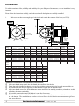
Stern thruster installation manual IMPORTANT NOTICE: This manual is to be used in addition to the regular installation manual for the Sidepower thruster. This manual is intended for professionals only, and does not contain all detailed work instructions for what must be done to ensure correct and safe installation of the sternthruster. m an Ke ua ep l o th nb is oa rd ! SLEIPNER MOTOR AS P.O. Box 519 N-1612 Fredrikstad Norway Tel: +47 69 30 00 60 Fax:+47 69 30 00 70 www.side-power.com [email protected] Made in Norway SIDEPOWER ® © SLEIPNER AS -2005 2010 © SleipnerMOTOR Motor AS Installation To achieve maximum effect, reliability and durability from your Sidepower Sternthruster, a correct installation is very important. Please follow the instructions carefully, and make sure that all checkpoints are carefully controlled. 1. Make sure that there are enough space both inside and outside the transom of the boat (see FIG 1). W.L. FIG. 1 D B C 60° Bolt holes diaG : Bolt postion radiusH: Outside of flange: F PS ! Necessary support of motor. Minimum is hulls bottom thickness Cut out in stern: E A ø98mm / 3,86'' ø98mm/3.36” 14mm/0.55” 14mm / 0,55'' Measurements SH100 Measurements ref. mm/inch SP100HYD SH100 mm / inch A 172mm/6.72” A 158mm / 6,22" B 256mm/10.08” B 256mm / 10,08" C 200mm/7.87” C 200mm / 7,87" D 337mm/13.30” D 337mm / 13,30" E ø300mm/11.81” E ø300mm / 11,80" F ø200mm/7.84” F ø200mm / 7,84" G 6x G 6x ø10,5mm / 0,41" ø10,5mm/0.41” ø129mm / 5,08" ø129mm/5.08” - 8 H H Max. Stern Max stern thickness thickness SE80 SE100 SE120/SE150 SE130 SE170 ø129mm / 5,08" ø129mm/5.08” ø129mm / 5,08" ø129mm / ø129mm/5.08” 5,08" ø129mm / 5,08" ø129mm/5.08” ø129mm/5.08” ø129mm/5.08” 35mm/1.38” 35mm / 1,38" SH160 SP220HYD SH240 54mm/2.13” 54mm/2.13” 60mm 60mm/2.36” 54mm / 2,13" 54mm/2.13” 54mm / 2,13" / 2,36" SH240 SP300HYD SH420 SP300HYD SP550HYD SP300HYD SH420/550 172mm/6.72” 191mm/7.52” 195mm/7.68” 257mm/10.12” 178mm / 7,01" 208mm / 8,19" 259mm / 10,20" 300mm/11.81” 340mm/13.39” 420mm/16.54” 570mm/22.44” 340mm / 13,39" 420mm / 16,54" 570mm / 22,44" 215mm/7.87” 300mm/11.81” 300mm/11.81” 570mm/22.44” 300mm / 11,81" 300mm / 11,81" 380mm / 14,96" 330mm/13.00” 350mm/13.80” 456mm/18.00” 550mm/21.65” 350mm / 13,80" 456mm / 18,00" 550mm / 21,65" ø300mm/11.81” ø300mm/11.81” ø396mm/15.60” ø600mm/23.62” ø300mm / 11,80" ø396mm / 15,60" ø600mm / 23,62" ø200mm/7.84” ø200mm/7.84” ø265mm/11.40” ø400mm/15.75” ø200mm / 7,84" ø265mm / 10,40" ø400mm / 15,75" 6x 6x 8x 12 x 6x ø10,5mm / 0,41" 8x ø10,5mm / 0,41" 12x ø13mm / 0,51" ø10,5mm/0.41” ø10,5mm/0.41” ø10,5mm/0.41” ø13mm/0.51” ø129mm / 5,08" ø345,6mm / 13,60" ø530mm / 20,87" ø129mm/5.08” ø129mm/5.08” ø345,6mm/13.60” ø530mm/20.87” - - - 8 H SE60 8 H Max. Stern Max stern thickness thickness SE30/40 SE210 SP30Si / SP40Si SP55Si SP75Ti SP95Ti SP125Ti SP155TCi SP200TCi SE30/40 SE60 SE80 SE100 SE120 SE170 SE210 200mm/7.87” 225mm/8.90” 312mm/12.30” 349mm/13.70” 407mm/16.02” 363mm/15.10” 386mm/15.20” 419mm/16.50” 200mm / 7,87'' 225mm / 8,90" 312mm / 12,30" 349mm / 13,70" 363mm / 15,10" 386mm / 15,20" 419mm / 16,50" 190mm/7.48” 265mm/10.08” 256mm/10.08” 256mm/10.08” 300mm/11.81” 340mm/13.39” 340mm/13.39” 360mm/14.20” 190mm / 7,48'' 256mm / 10,08" 256mm / 10,08" 256mm / 10,08" 340mm / 13,39" 340mm / 13,39" 360mm / 14,20" 135mm/5.31” 150mm/5.91” 200mm/7.87” 200mm/7.87” 215mm/7.87” 250mm/9.54” 250mm/9.54” 300mm/11.80” 135mm / 5,31'' 150mm /5,91" 200mm / 7,87" 200mm / 7,87" 250mm / 9,84" 250mm / 9,84" 300mm / 11,81" 197mm/7.76” 337mm/13.30” 337mm/13.30” 337mm/13.30” 330mm/13.00” 350mm/13.80” 350mm/13.80” 350mm/13.80” 197mm / 7,76'' 337mm / 13,30" 337mm / 13,30" 337mm / 13,30" 350mm / 13,80" 350mm / 13,80" 350mm / 13,80" ø217mm/8.54” ø300mm/11.81” ø300mm/11.81” ø300mm/11.81” ø300mm/11.81” ø300mm/11.81” ø300mm/11.81” ø356mm/14.02” ø217mm / 8,54'' ø300mm / 11,80" ø300mm / 11,80" ø300mm / 11,80" ø300mm / 11,80" ø300mm / 11,80" 356mm / 14,02" ø160mm/6.3” ø200mm/7.84” ø200mm/7.84” ø200mm/7.84” ø200mm/7.84” ø200mm/7.84” ø200mm/7.84” ø260mm/11.24” ø160mm / 6,30'' ø200mm / 7,84" ø200mm / 7,84" ø200mm / 7,84" ø200mm / 7,84" ø200mm / 7,84" ø260mm / 11,24" 6x 6x 6x 6x 6x 6x 6x 8x 6 x ø6,5mm / 0,26'' 6x ø10,5mm / 0,41"ø10,5mm/0.41” 6x ø10,5mm / 0,41" 6x ø10,5mmø10,5mm/0.41” / 0,41" 6x ø10,5mm / 0,41" 6x ø10,5mm / 0,41" 8xø10,5mm/0.41” ø10,5mm / 0,41" ø6,5mm/0.26” ø10,5mm/0.41” ø10,5mm/0.41” ø10,5mm/0.41” ø10,5mm/0.41” 8 Measurements Measurements mm/inch ref. mm / inch A A B B C C D D E E F F G G ø129mm / 5,08" ø129mm/5.08” ø315mm / 12,40" ø315mm/12.40” 60mm/2.36” 60mm / 2,36" 50mm/1.97” 50mm / 1,97" SP200TCi-32/ SP200TCi-32 / SP240TCi SP240TCi 440mm/17.30” 440mm / 17,30" 420mm/16.54” 420mm / 16,54" 300mm/11.81” 300mm / 11,81" 456mm/18.00” 456mm / 18,00" ø396mm/15.60” ø396mm / 15,60" ø265mm/11.40” ø265mm / 10,40" 8x 8x ø10,5mm / 0,41" ø10,5mm/0.41” SP285TCi 404mm/15.90” 404mm / 15,90" 420mm/16.54” 420mm / 16,54" 300mm/11.81” 300mm / 11,81" 456mm/18.00” 456mm / 18,00" ø396mm/15.60” ø396mm / 15,60" ø265mm/11.40” ø265mm / 10,40" 8x 8x ø10,5mm / 0,41" ø10,5mm/0.41” ø345,6mm ø345,6/13.60”/ 13,60" ø345,6mm ø345,6/13.60”/ 13,60" 60mm/2.36” 60mm / 2,36" SP285TCi 60mm/2.36” 60mm / 2,36" SH550 257mm/10.12” 570mm/22.44” 570mm/22.44” 550mm/21.65” ø600mm/23.62” ø400mm/15.75” 12 x ø13mm/0.51” ø530mm/20.87” - - Additional considerations for positioning of stern thruster. Make sure that the stern-tunnel does not disturb the waterflow under the hull Ensure that when installed the thruster does not foul exisiting equipment inside the boat like steerage links etc. It is essential that the motor is supported so that the total weight is not on the tunnel alone. Make sure that the water flow from the thruster are not intereferred to much by sterndrives, trimtabs etc. as this will reduce the thrust considerably. It is possible to mount the tunnel off the boat’s centre line if necessary. If the stern thickness is to much for the thruster in question you can easily remove material in the necessary area to fit the thruster. The stern thickness even here will never have to be less than the max. measurement given as max. stern thickness. 2 Stern thruster installation manual Version 1.6 - 2005 Version 1.7.1 - 2010 BOLT ON INSTALLATION 2a. Once the place for the installation has been decided, hold the tunnel in place in the horizontal position and mark the bolt holes. Remove the tunnel and it is then possible to calculate and mark the centre (see Fig. 1). 3a. It is important that the tunnel flange sits flush on the transom. If this is not case, then the fitting area on the transom will have to be worked to ensure a snug fit. PS ! Take care with grinders as it is very easy to remove to much fibreglass At this time, cut out the centre hole and the transom to the same internal diameter as the tunnel flange and drill the bolt holes. Before actual fitting the stern tunnel, we recommend that the prepared area is sealed with a gelcoat or similar to ensure there is no water ingress. 4a. Before fittingthe thetunnel tunneltoto transom, install the gearleg the tunnel as described in the thruster Before fitting thethe transom, install the gear leg to thetotunnel as described in the thruster installation installation manual. For thrusters with external oil tank, we recommend that the oil feed pipe manual. We recommend that you fit the oil feed pipe also before the tunnel is bolted to the transom.is fitted before tunnel istpoints bolteddescribed to the transom. Specialthe installation on page 7 of this manual. 5a. When fitting the tunnel, ensure that there is ample sealant (Sikaflex or similar) in the sealing tracks of the tunnel flange and around the bolts to make a water tight fitting (see FIG. 2&3). Bolts, washers and nuts are not included as they will vary depending on the transom thickness. We recommend A4 stainless with A4 lock nuts and A4 washers of a large diameter on both outside and inside. 6a. 7a. Bolts diameter (stainless steel): øø 6mm or1/4” 1/4”for forSP SE40/SE60 6mm or 30 Si & SP 40 Si øø 10mm 10mm or or3/8” 3/8”for forSP SE60/SE80/SE100/SE120/SE130/SE150/SE170/SE210/SE285 55 Si & SP 75 Ti & SP 95 Ti & SP 125Ti & SP 155 TCi SH100/SH160/SH240/SH300 ø 12mm or 1/2” for SP200TCi & SP 240 TCi & SP 285 TCi ø 12mm or 1/2” for SH420/SH550 FIG. 2 The electromotor must have a solid support so that the weight can not cause a twisting action on the tunnel (see FIG. 4). Refer to the installation manual for the recommended thruster fitting. SEALANT SEALANT FIG. 3 FIG. 4 Motor support MUST be installed WASHERS LOCKNUT OR DOUBLE NUTS Stern thruster installation manual Version 1.7.1 1.6 - 2005 - 2010 3 WARNING! MOULD IN INSTALLATION 2b. Cut of the bolting flange on the stern-tunnel 3b. Grind off the gelcoat both inside and outside the remaining “tube” atleast 10 cm down on the “tube” (see FIG. 5). 4b. Offer the stern tunnel to the desired position on the transom and mark around the tube. 5b. Cut the marked hole in the transom of the boat. 6b. Grind off the gelcoat on the transom of the boat in an area of atleast 10 cm / 4” around the hole, both outside and inside (see FIG. 5). 7b Offer the stern tunnel to the transom in the desired horizontal position, then bond to the transom with multi layers matt both inside and outside (see FIG. 6). Take care not to reduce the internal diameter much, as this will make it more difficult to mount the thruster 8b Install the gear leg on the stern-tunnel as described in the installation manual for the thruster but fit the oil feed pipe first. (for models with externalinstallation oil tank) points described on page 7 of Special this manual. 10b. The electromotor must be sturdily supported so that the weight-arm tension from the motor weight are not applied only on the tunnel (see FIG. 4) 4 Composite stern tunnels (Part # 90052i 90086ican ) Composite sternand tunnels can not moulded in in this NOT bebemoulded thisway. way. FIG. 5 Grind off the bolt flange and the gelcoat both inside and outside in the areas shown. Boat transom Boat transom Stern tunnel Apply gelcoat or similar on all bonded areas. 9b. 11b. Mould in IN installation is ONLY MOULD installation is for for stern GRP tunnels. GRP Tunnels ONLY! FIG. 6 Bond multiple layers both inside and outside Basic installation of the flexible coupling, motor and electrical installation are described in the thruster manuals. Stern thruster installation manual Version 1.7.1 1.6 - 2005 Version - 2010 THE STERN-THRUSTER MUST BE KEPT DRY AT ALL TIMES It is very important that you do everything possible to ensure that the thruster stays dry at all times. The electromotor and and solenoid system is not to be considered as waterproof, and will be dammaged if they keep getting wet (rust and corriosion). Therefore, the thrusters installation compartment must be kept dry at all times. This is more difficult for a sternthruster installation than for a bowthruster installation as the sternthruster has to be fitted in the bilge at the stern of the boat. This is generally a “wet” area that must be transformed into a dry area. Important precautions ! - You must seal all drain holes going into the compartment of the thruster. - The surrounding compartments and any plates or compartments above must be drained in a good way to the bilge area in front of the thrusters installation compartment. - If the propeller shaft or other moving parts with a high possibility for leakage comes through the bottom of the boat in the same compartment where the thruster is placed, you must make a seperate compartment for the thruster isolating it from these very normal and highly probable water leakages. - The rudder shaft entrances to the boat and its surroundings must be drained so that any water coming in here are drained to go into the compartment in front of the sternthruster compartment. - It is also important to ensure that the sternthrusters installation compartment will not be were water runs if a selfdraining system of the boat deck fails to operate properly. - Generally, all possible actions should be taken to ensure that water leakages from sources that are likely to have water leakages are drained to prevent water from entering the stern-thruster compartment. - We advice to install a self-activating bilge-pump, preferably with an alarm system, in the stern-thruster compartment. If you are not confident that you have been able to seal this comparment well, this pump is absolutely necessary. - The control-cable system for the thruster must be installed so that atleast all junctions and connectors are kept dry at all times. - In the Sidepower sternthruster kit, there will be included a cable, so that electronic controlbox originally placed on the electromotor, can be fitted away from the thruster in a higher position securing that it will stay dry at all times, even if there are accidental leakages into the stern-thruster compartment. Please see instructions on the following pages of how to connect this. If you are installing a sternthruster without the special sternthruster tunnel available from Sidepower, this kit can be bought seperately. Wet bilge area Stern thruster installation manual The thruster compartment must be kept dry at all times Thruster compartment must be kept dry at all times Version - 2010 Version 1.7.1 1.6 - 2005 5 THE STERN-THRUSTER MUST BE KEPT DRY AT ALL TIMES Description of illustrations: A : All draining holes or other openings from wet areas into the thruster installation compartment must be sealed. D C B: Originally non-sealed bulkhead F B H C: Stringers in the boats lenght directions, normally there are drain holes through these from side-compartments A D: Plate above bilge where the steering system and other technical installations are often installed G E: Watertight bulkhead to engine room. F F: Thruster G: Ensure there are draining holes in these positions to lead the water to the bilge to be pumpe out. H Make anti drip edges on all surfaces above the thruster compartent to ensure that any water here will go via the drain holes and to the wet part of the bilge. A B C G E H E D B A 6 Stern thruster installation manual F Version 1.7.1 1.6 - 2005 Version - 2010 SPECIAL INSTALLATION INSTRUCTIONS Side-Power SP55 (old model) Sidepower SP 55 Si As the motorbracket are completely inside the stern-tunnel, the oil-pipe must be changed to an elbow connection so that the oil hose will not be bent, preventing from constrictions. 1. 2. Remove the straight hose pipe in the bracket. Install the elbow hose pipe connection that came with the stern-tunnel, be sure to use a sealant on the threads, but not so much that it closes the oil feed into the bracket. SH100/SH160 & /older SP75/SP95/SP125 SSide-Power idepower SP75Ti / SP95Ti SP125Ti / SP100HYD models As there are no room to place and fasten the lower part of the flexible coupling after the electric motor is fastened on the bracket, this must be done before fitting the motor. PS! The part of the flexible coupling that is fastened on the motor, is prefixed in a specific position, on which this procedure FIG. 8 is based. DO NOT MOVE IT ! 1. 2. 3. When the gearhouse and bracket are mounted on the sterntunnel, place the lower part of the coupling on the driveshaft. Adjust the height of the lower part of the coupling to the measurement given in FIG. 8 Apply a thread glue (Locktite or similar) to the set screws and fasten the coupling by tightening both setscrews. Side-Power SE210/SE240/SE285/SH240/SP300HYD Sidepower SP155TCi / SP200TCi / SP240TCi / & older SP155/SP200 models SP285TCi / SP220HYD / SP300HYD The lower part of the flexible coupling does not have to be tightened to the driveshaft. The fastening on the motor is sufficient. PS! Make sure the key on the shaft is in its correct position when sliding the motor with the flexible coupling onto it (see FIG. 9). FIG. 9 7 Stern thruster installation manual Version - 2010 Version 1.7.1 1.6 - 2005 REMOTE INSTALLATION OF THE ELECTRONIC BOX. As the electronic controlbox and its contact are the most sensitive parts on the thruster, we advice that these are removed from the thruster and fitted in a high place in the boat so to secure these from water ingress, even if the thrusters compartment gets flooded. Included with the stern-thruster tunnel kit is an extension cable that will allow you to do this. Procedure: 1 Exchange the GREY and BLUE wires on the sides of the main solenoids that is coming from the electronic controlbox with the GREY and BLUE wires from the extension cable. 2. Exchange the BLACK, BROWN and WHITE wires from the electronic controlbox with BLACK , BROWN and WHITE wires in the extension cable. 3. Cut the strips holding the RED internal connections together with the other internal connections, and leave the RED wires on the main solenoids. Cut the red wire in accordance to drawing. 4 Remove the electronic controlbox and its harness from the solenoid system on the thruster. 5 Locate and fasten the electronic controlbox in a position where it will surely keep dry. This should be relatively high in the boat, so that even an extreme level of bilge water can not get to it. Also ensure that the position is safe against water running from above. 6 Remove the electronic controlbox from its original harness and plug it into the connector on the extension cable. 7. The extension cable to the control panel(s) must now be connecte to the AMP male plug on this remotely installed controlbox. Ensure that all controlcable junctions/connectors are placed so that Electronic controlbox they will stay dry at all times. placed high, away from splashing water. SIDE-POWER Electronicinterface for thr uster motor controls Ref #6 1230 i Sleipner Motor AS N-1612Fredrikstad New connector for electronic controlbox SIDE-POWER Electronic controlbox to be removed from thruster AMP male connector to control panel (s) Connectors to thruster 2m extension Wet bilge area EXISTING HARNESS REMOVED EXISTING HARNESS STERN EXTENSION HARNESS INSTALLED New Brown Brown New Black Black N- 1 612 Fr ed ri kst a d Sl ei pn er M ot or AS Red Red New Red Blue New Blue Grey New Grey SI DE- P OW ER E le c tr o n i c in te r fa c e fo r th r u s t e r m o t or c o n tr o ls White R ef # 6 123 0i S le p i n er M ot or A S N - 1612 F re dri kst ad Stern thruster installation manual Version - 2010 Version 1.7.1 1.6 - 2005 8 R e f # 6 1 230 i A2 Bolt New White S ID E- P O W E R Red Existing Red (after cutting) E le c tr o n ic i n te r fa c e f o r th r u st e r mo t o r co n t ro l s Cut the Red wire as close as possible to contact ELECTRICAL INSTALLATION OF STERNTHRUSTER SYSTEMS PS ! This is additional information especially for sternthruster installations, and the installation manual for the thruster you are installing must be used complementary. If a bow thruster is also installed, we strongly advice to use seperate battery banks for the two thrusters to avoid extreme voltage drop if both thrusters were to be used at the same time, and to ensure maximum performance. Battery banks must have common minus! Refer to the thruster manuals for advised battery capacity and cable sizes for each thruster. If a single control panel other than Sidepower’s is to be used for both bow and stern thruster, be sure it has a single positive connection from only one of the two thrusters to avoid current leakage between the two battery banks. If you are installing the standard Sidepower dual joystick panel this is already taken care of. Wiring diagram for installation with original Sidepower dual joystick panel. When using the original Sidepower control cables just connect them to the corresponding joystick There are no plus/positive power connected from the sternthruster Visual connection diagram for dual joystick panel SIDEPOWER THRUSTERS To bowthruster BOW To sternthruster STERN ON ON OFF SLEIPNER Wiring diagram (simplified) for dual joystick panel Positive lead from sternthruster has been removed in panel to avoid current leakage between battery banks if the thrusters are powered by different battery banks. grey blue black Control light Joystick for bowthruster ON / OFF System STERN Stern thruster installation manual red grey blue black Joystick for sternthruster BOW - 2010 Version 1.7.1 1.6 - 2005 9 ELECTRICAL INSTALLATION OF STERNTHRUSTER SYSTEMS To use the Sidepower dual joystick panel with previously installed Sidepower bowthruster with the older 3 lead electric system. - Please contact your distributor / dealer to purchase an upgrade kit to rebuild your existing bowthruster to the new 4 lead electric system. The wiring diagram on the previous page will then be the correct one for your complete system. To use the Sidepower dual joystick panel with previously installed thruster of other brand. - You should not use the Sidepower dual joystick panel as it is not designed to run other thruster brands. It may be possible but you must consult a skilled electrician to ensure the compatibility. The panel can supply a maximum of 1Amp. in the standard configuaration and will therefore normally not be able to directly drive main solenoids on a thruster. - If you wish to use this panel to control another brand of bowthruster, a possible solution is to rebuild the dual joystick panel, so that it for all practical purposes is transformed into two different controls. This is done by removing all connections on the “bow-joystick” including the Sidepower connector and the yellow cables between the two joysticks. You must then connect the black lead coming out of the ON/OFF system in the panel to a seperate ground/negative with the same ground potential the thrsuter because there are no ground coming from the sternthruster. By this, the “bow-joystick” is totally seperated from the Sidepower panel and can be used and connected as any other joystick or two way switch. Consult your other brand thruster manual for correct connections. We advice to always fit an ON/OFF switch on the input lead to the joystick so that it’s function can be de-activated when the thruster is not in use. See example diagram below. Visual connection diagram for rebuilt dual joystick panel To other brand bowthruster Control power FUSE SIDEPOWER ON / OFF THRUSTERS RH / LH run BOW LH / RH run W BO To Sidepower sternthruster STERN ON ON OFF SLEIPNER Remove the yellow jumper between BOW and STERN joysticks at the back of the panel. Move the two grey leads from the BOW joystick to the STERN joystick (a total of four grey leads at STERN joystick) Move the two blue leads from the BOW joystick to the STERN joystick (a total of four blue leads at STERN joystick) Contact marked with STERN is NOT in use! NB! 10 Sleipner Motor claims no compatibility with other thruster brands and assumes no responsibility for connection or usage with other thruster brands. Stern thruster installation manual Version - 2010 Version 1.7.1 1.6 - 2005 INSTALLATION CHECKLIST There is a sturdy additional support under the electric motor, taking the weight/ load of the electromotor away from the stern-tunnel. All bolts are securely tightened and sealant is applied as instructed All necessary actions have been taken to ensure that the thrusters installation compartment will stay dry at all times. The electronic controlbox of the thruster have been remotely fitted in a high place where there are no chance it will be submerged or splashed with water. All electrical wiring, cable sizes and battery capacity is according to the thruster installation manual. The unit has been moved by hand and found to run freely. The gear house, oil-hose and oiltank are filled with oil (models with external oiltank). The gearoil tank is installed a minimum of 200mm above the waterline. (models with external oiltank). IMPORTANT USER ADVICE Never use the thruster if there are people or animals swimming in the area around the thruster. The thruster propeller can cause serious injuries when it is running. WARNING ! Never store any items that can leak explosive gas in the same room where the sternthruster is fitted. The thruster will create sparks that can cause an explosion if there are explosive gases present. When the boat is going backwards in a “dirty” harbour with lots of floating objects / debris, this can be “collected” by the transom of the boat. These objects / debris can cause damage to the thruster if sucked into the tunnel while the thruster are being operated. All the thrusters are built with safety devices (shearpin inthe theSP30Si SE 30 / SP40Si SE 40 //SE 60 &&flexible SE 80 / /SE 100 // SH 100 / SE120 (shearpin in SP55Si flexiblecouplings couplings in the SP75Ti SP95Ti SP100HYD / SE 130 / SE 170 / SE/210 / SH160/SH 240 / SP240TCi / SP285TCi / SP300HYD / SH 420 / SH 550 SP125Ti / SP155TCi SP200TCi / SP220HYD / SP240TCi / SP285TCi / SP300HYD / SP550HYD models) changeable from inside the boat, but damages can occur to other parts of the thruster in certain cases. Always turn of the main power / disconnect the thruster from the batteries before touching any moving parts of the thruster inside or outside the boat. If the thruster does not move the boat/does not give any thrust you must immediately stop trying to run it and turn off the main power switch until the reason for this is found and corrected. This manual is in addition to the general thruster manual, so this must be read and understood also ! IMPORTANT NOTICE Sleipner Motor AS assumes no responsibility or liability for the installation of any components. Skilled installers should be used, and there might be unforeseen factors that can make one or more installation instructions wrong or not entirely correct for the boat in question. The installation responsibility is thereby solely on the party that are actually performing the installation. STERNTHRUSTER TUNNEL INSTALLED BY: ........................................................................................ DATE:............................. INSTALLED THRUSTER: .................................................................... Stern thruster installation manual Version 1.7.1 - 2010 Version 1.6 - 2005 11 Service Centres Cyprus Ocean Marine Equipment Ltd Limassol Tel: +357 253 69731 Fax: +357 253 52976 [email protected] Argentina Trimer SA Buenos Aires Tel: +54 11 4580 0444 Fax: +54 11 4580 0440 www.trimer.com.ar [email protected] Denmark Gertsen & Olufsen AS Hørsholm Tel: +45 4576 3600 Fax: +45 4576 1772 www.gertsen-olufsen.dk [email protected] Australia AMI Sales Freemantle, WA Tel: +61 89 331 0000 Fax: +61 89 314 2929 [email protected] Austria G. Ascherl GmbH Hard, Bregenz Tel: +43 5574 899000 Fax: +43 5574 89900-10 www.ascherl.at offi[email protected] Benelux ASA Boot Electro Watergang Tel: +31 20 436 9100 Fax: +31 20 436 9109 www.asabootelectro .nl [email protected] Brazil Electra Service Ltda. Guaruja Tel: +55 13 3354 3599 Fax: +55 13 3354 3471 www.electraservice.br.com [email protected] Bulgaria Yachting BG Burgas tel: +359 56 919090 fax: +359 56 919091 www.yachting.bg [email protected] China/Hong Kong Storm Force Marine Ltd. Wanchai, Hong Kong Tel: +852 2866 0114 Fax: +852 2866 9260 www.stormforcemarine.com [email protected] South Africa C-Dynamics Cape Town Tel: +27 21 555 3232 Fax: +27 21 555 3230 www.c-dynamics.co.za [email protected] Italy Saim S.P.A. Assago-Milan Tel: +39 02 488 531 Fax: +39 02 488 254 5 www.saim-group.com Spain Imnasa Marine Products Girona Tel: +34 902 300 214 Fax: +34 902 300215 www.imnasa.com [email protected] Japan Turtle Marine Inc. Nagasaki Tel: +81 95 840 7977 Fax: +81 95 840 7978 www.turtle-marine.com [email protected] Sweden Sleipner AB Strömstad Tel: +46 526 629 50 Fax: +46 526 152 95 www.sleipnerab.se Finland Nautikulma OY Turku Tel: +358 2 2503 444 Fax: +358 2 2518 470 www.nautikulma.fi nautikulma@nautikulma .fi Malta S & D Yachts Ltd. Cali Tel: +356 21 339 908 Fax: +356 21 332 259 www.sdyachts.com [email protected] Switzerland Marine Parts Technics AG Volketswil Tel: +41 1 997 40 90 Fax: +41 1 997 40 94 www.marineparts.ch [email protected] France Kent Marine Equipment Nantes Tel: +33 240 921 584 Fax: +33 240 921 316 www.kent-marine.com [email protected] New Zealand Advance Trident Ltd. Auckland Tel: +64 9 845 5347 Fax: +64 9 415 5348 www.advancetrident.com [email protected] Singapore/Malaysia/ Indonesia/Vietnam/Phillipines Island Marine Services Pte Ltd Singapore Tel: +65 6795 2250 Fax: +65 6795 2230 www.island-marine.com [email protected] Germany Jabsco GmbH Norderstedt Tel: +49 40 535 373-0 Fax: +49 40 535 373-11 Greece Amaltheia Marine Athens Tel: +30 210 2588 985 Fax: +30 210 2588 986 www.amaltheiamarine.com [email protected] Canada Imtra Corporation New Bedford, MA Tel: +1 508 995 7000 Fax: +1 508 998 5359 www.imtra.com [email protected] Croatia Yacht Supplier Icici Tel: +385 51 704 500 Fax: +385 51 704 600 [email protected] Estonia/Latvia/Lithuania Miltec Systems OÜ Tallin Tel: +372 5013997 Fax: +372 6442211 www.miltec.ee [email protected] Israel Atlantis Marine Ltd. Tel Aviv Tel: +972 3 522 7978 Fax: +972 3 523 5150 www.atlantis-marine.com [email protected] Iceland Maras EHF Reykjavik Tel: +354 555 6444 Fax: +354 565 7230 www.maras .is gummi@maras .is Norway Sleipner Motor AS Fredrikstad Tel: +47 69 30 00 60 Fax: +47 69 30 00 70 www.side-power.com [email protected] Poland Taurus Sea Power SP. Z.O.O Gdansk Tel: +48 58 344 30 50 Fax: +48 58 341 67 62 Portugal Krautli Portugal Lda. Lisboa Tel: +351 21 953 56 00 Fax: +351 21 953 56 01 www.krautli.com [email protected] Russia India Indo Marine Engineering Co. Pvt. Ltd Standarte Starbeyevo Pune, Maharashtra Tel: +7 495 575 67 23 Tel: +91 20 2712 3003 Fax: +7 495 575 39 77 Fax: +91 20 2712 2295 www.standarte.ru [email protected] [email protected] Ireland Sleipner Motor Ltd. South Brent Tel: +44 1364 649 400 Fax: +44 1364 649 399 [email protected] Taiwan Mercury Marine Supply Kaohsiung Tel: +886 7 3317 293 Fax: +886 7 3314 232 Turkey Denpar Ltd. Istanbul Tel: +90 212 346 1332 Fax: +90 212 346 1329 [email protected] UK Sleipner Motor Ltd. South Brent Tel: +44 1364 649 400 Fax: +44 1364 649 399 [email protected] United Arab Emirates Teignbridge Propellers & Marine Equipment Co. Ltd. Dubai Tel: +971 4 324 0084 Fax: +971 4 324 0153 [email protected] USA Imtra Corporation New Bedford, MA Tel: +1 508 995 7000 Fax: +1 508 998 5359 www.imtra.com [email protected] Sleipner Motor AS • P. O. Box 519, N-1612 Fredrikstad • Norway Tel: +47 69 30 00 60 • Fax: +47 69 30 00 70 • [email protected] • www.side-power.com