1
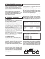
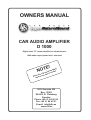
OWNERS MANUAL
CAR AUDIO AMPLIFIER
D 1000
Digital class ”D” mono amplifier for subwoofer use
1000 watts output power into 1 ohm load
!
E
T
NO
hly
oug ll
r
o
a
th
ual to inst
n
a
m
rt
his ou sta
t
d
Rea fore y
be
DLS Svenska AB
Box 13029
SE-402 51 Göteborg
Sweden
Phone +46 31 84 00 60
Fax +46 31 84 40 21
E-mail: [email protected]
www.dls.se
TABLE OF CONTENTS
Congratulations, you have just purchased the finest Car Audio amplifier that today´s technology can offer.
DLS offers a series of high quality car audio products for real music lovers, and we are sure that you will
enjoy a high class car sound for many years.
Read the owners manual first!
To maximize the performance of your system, we recommend that you thoroghly acquaint yourself with it´s
capabilities and features. Please take your time to study this manual before starting the installation. Then
you hopefully know how to do a correct installation avoiding connecting errors that can cause damage to
this fine product. Retain this manual for future reference.
TABLE OF CONTENTS:
Page 2
1. GENERAL PRODUCT INFORMATION
Page 2
Page 2
Page 2
Page 3
Page 3-4
Page 4
Page 4
Page 4
2. INSTALLATION PREPARATION
2.1 Location
2.2 Power cables
2.3 Signal cables
2.4 Speaker connection, speaker loads, speaker polarity check
2.5 Level setting
2.6 Final system setup
2.7 Protection circuits
Page 4
Page 4
Page 4
3. INTERNAL FILTERS
3.1 Lowpass / Highpass
3.2 Bass boost
Page 5
Page 5
4. FAULT FINDING GUIDE
4.1 Noise problems
Page 5
5. REMOTE SUB LEVEL CONTROL
Page 5
6. SPECIFICATIONS
Page 6
7. CONNECTION DIAGRAM
Page 7
For your own notes
CAUTION!
Some of our amplifiers are capable of producing a sound pressure level that can cause permanent
damage to your hearing system. High sound pressure levels combined with long time listening can give
permanent damage to your hearing system. Choose a listening level that is comfortable for your ear.
To establish a safe level:
Start your volume control at a low setting. Slowly increase the volume until you can hear the music
comfortly and clearly, without any distortion. Sudden sound shocks are dangerous.
The following noises can be dangerous with constant exposure:
90 dB
Subway, motorcycle, lawn mover
4 hours max
100 dB
Chain saw
2 hours max
120 dB
Rock band live concert
30 minutes max
140 dB
Gunshot blast, jet plane
0 minutes
-1-
GENERAL, POWER CABLING
1. General product information
Thank you for buying a DLS amplifier. This amplifier
is a high quality product and is a result of many
years of experience of building high quality sound
products for vehicles.
We recommend you to carefully read this manual
before you start to install. Be sure to follow all
recommendations in the installation section. If you
do so we are sure that you will be able to enjoy a
perfect sound for a long time,.
2. Installation preparation
2.1 LOCATION
We recommend you to do a careful planning before
you start to install this equipment.
Choose a location for the amplifier which will allow
plenty of air to circulate around the fins on the top of
the case. Vertical mounting is to prefer. Do NOT mount
the amplifier upside down under the hat rack.
In the amplifier case there are double mounting holes
to make the installation job easier. The screws
supplied in the plastic bag are self drilling when used
with an electric screwdriver.
If the surface where you intend to mount the amplifier
isn´t big enough you can mount the amplifier on a
separate fibre board or similar. This will also isolate
the amplifier chassies from ground.
NOTE! Before you start drilling, make sure that
there are no fuel or brake lines or wiring looms
behind where you intend to drill.
2.2 POWER CABLES
The DC power wiring is extremely important. It is
essential that the amplifier at all occassions gets all
the power it needs without voltage drop, otherwise
both the dynamics and the good sound will be lost.
A poor battery can also cause a bad sound
reproduction, escpecially in the bass range. Sometimes it is necessary to mount an extra battery.
The speaker cable connections requires a 2 mm hexagon key to connect the terminals, and the power cable
connections require a 4 mm hexagon key.
In most cases a so called ”Power Cap” can be useful.
It is an energy storage capacitor designed to supplement audio amplifiers during high current demand. The
overall bass response of your audio system will be
enhanced with the use of this due to it´s ability to
store a large amount of current and discharge it in a
short period of time.
In the table below you will find suitable cable and fuse
sizes for different cable lenghts.
The gold plated terminals will directly recieve
power cables up to 21 mm2 (4AWG).
Mount the fuse holder included in the amplifier on the
DC -cable near the positive battery terminal. Use the
same cable size from the negative amplifier terminal
and connect to the nearest earth point.
The Fuse holder accepts cables up to 21mm2 if you
remove the inner bushing. If you are using heavier
cables use another type of fuse holder or cut some of
the strands in the cable.
Make sure to have a good earth contact, if necessary
clean the metal from paint etc. A poor earth contact
can cause damage to other parts in the system, for
example the head unit if the earth current is forced to
pass through the shield of the signal cable.
Recommended cable size for the DC-feed.
Cable length:
D 1000
< 1,5 m
16 mm2
1,5 - 5 m
>5m
21 mm2 33 mm2
Recommended main fuse for D 1000:
Amplifier
D 1000
Fuse value
AGU 80 A
Fuse holder
FH1/FH1B
A cable of a certain size can´t have an oversized fuse,
then the cable gets too warm before the fuse blows.
Max fuse values for different cable sizes:
6 mm2 (9 AWG) 25 A
10 mm2 (7AWG) 40 A
16 mm2 (5AWG) 60 A
21 mm2 (4AWG) 100 A
33 mm2 (2AWG) 140 A
42 mm2 (1AWG) 200 A
If you have more than one amplifier in the system
you must increase the cable size and fuse compared
to the table. When connecting two or more amplifiers
use some of the DLS Fuse blocks with built in fuses
to split the power to each amplifier. The short cable
from the Fuse block to the amplifier can have a smaller size for easier installation.
Don´t connect to battery before you have double
checked all connections.
Fuse block
Fuse
Battery 12 V
-2-
2 amplifiers
CABLING, SIGNAL CABLES, SPEAKER CONNECTION
2.3 SIGNAL CABLES
PROTECT YOUR CABLES!
D 1000 has two gold plated phono socket pairs. The
upper pair is used to recieve the signal from the head
unit and the lower pair has a line out function if you
want to connect to more amplifiers.
Both inputs must recieve an input for full power output.
Use high quality interconnects like the DLS SL5 PRO
or similar with an effective shielding that prevents
interference from the engine or alternator. When
using this cable you must run a separate wire for the
remote.
When you run the signal cables remember to keep
them well spaced from the wiring loom and the power
feed to the amplifier to avoid picking up interference.
Lay the power cables and signal cables separated
on each side of the car. Any extra cable must be laid
in zig-zag style and definitely not coiled. Or cut it to
correct lenght.
REMOTE WIRE
Some signal cables include a thin wire for remote
amplifier start. High quality cables normally requires
a separate wire for this. Connect between the head
units remote cable (often the same cable that´s used
for automatic power antennas) and the REM-terminal on the amplifier.
NOTE! If you want to start more than one amplifier
using the remote output, the current load might be
too high for som head units. High currents may
damage the head unit, check in the manual for the
head unit. Sometimes you must add a relay to the
remote circuit that takes care of the higher current. If
you are uncertain of how to connect the relay, ask
your local DLS dealer for advice.
To prevent the cable insulation from beeing damaged
over sharp metal edges we recommend the use of
cable protection tubes or similar. A damaged cable
insulation could cause serious damage to the amplifier
not covered by any guarantee.
SPEAKER POLARITY CHECK.
All speakers in a car audio system should be
connected in phase (the same polarity). All speaker
cones must move in the same direction. Out of phase
speakers will cause a lack of bass, and a poor stereo
soundstage.
Checking polarity:
Hold the - connection of the speaker wire to the terminal of a 1,5 Volt flashlight battery. Tap the + wire
on to the + terminal of the battery, and observe the
movement of the cone. The cone should move
outwards when the wire touches the battery, and
inwards when the battery is removed. If it is the other
way around, the speaker has been connected
backwards and it must be removed and connected
correctly.
If your system also has a subwoofer connected
through a passive 6 or 12 dB crossover, try to connect
this with various polarity and judge what sounds best.
The phase shift in passive crossovers sometimes
makes it necessary to change polarity.
+
Battery
1,5
Volt
+
-
NOTE! Tweeters can not be tested this way, double
check the connections instead.
SPEAKER LOADS
2.4 SPEAKER CONNECTION
There are double speaker connections internally
connected to each other. The reason for having
double connections is for making it easier to
connect more than one speaker.
The gold plated terminals will directly recieve
speaker cables up to 6 mm 2 (9AWG). Always
use high quality speaker cables such as DLS
SC 2x2,5 or SC 2x4.
Connect the speaker + (marked with + or a red
dot) to the amplifier + terminal, and the speaker
- to the amplifier -.
When fitting the cables to the terminals, remove
only 10 mm of the insulation. Twist the wire
strand together and insert the wire after
loosening the terminal screw. Do not over tighten
as this can cut the cable strands. Use a 2 mm
hexagon key to the terminals.
Most car audio speakers have a 4 ohm impedance.
D 1000 can be loaded down to 1 ohm.
When loaded with one 4 ohm speaker the output power
is 350 Watts. When loded with two 4 ohm speakers in
prallel (2 ohm load) the output power is 700 Watts,
and when loaded with four 4 ohm speakers connected
in parallel the output power is up to 1000 Watts.
On page 4 you find different speaker wiring examples.
-3-
SPEAKER CONNECTION, FILTER SETTINGS
SPEAKER CONNECTION EXAMPLES
2.6 FINAL SYSTEM SETUP
Before connecting the amplifier to the battey, recheck
all connections. When you connect the main fuse
you will see a little spark, this is normal. But if the
fuse blows at this moment, something is wrong.
Recheck the cabling.
Turn on your head unit, the amplifier starts and the
green POWER LED is lit. Increase the volume and
make sure all speaker works. Readjust levels and
crossover settings if necessary.
TWO 4 OHM SPEAKERS IN PARALLEL.
+
+
+
2 ohm
-
-
2.7 PROTECTION CIRCUITS
TWO 4 OHMS SPEAKERS IN SERIES.
+
+
+
-
-
PROTECTION LED
The amplifier has internal protection. The red
protection LED is illuminated when fault condition
exists and the amplifier immideately shuts down. If
illuminated, turn amplifier off, check for shorted speaker wires and attempt to re-power amplifier. When
the amplifier overheat and thermal protection shuts
the amplifier off, the LED does not illuminate.high
current protection circuit shutting down the amplifier
if the current draw is too high.
OVERLOAD LED
Allow self-test when power is turned on and then LED
should be illuminated during checking. It should be
automatically turned off 3 seconds later. It will
illuminate if there is trouble like speaker short or if
any part of the amplifier is overloaded.
8 ohm
-
Not a recommended way to connect, the power is
only half.
PARALLEL TO 1 OHM.
+
1 ohm
3. Internal filters
3.1 Lowpass / Highpass
Each speaker is 4 ohm
D 1000 has an internal variable lowpass filter. It can
be set from 35 up to 250 Hz. It also has an internal
higpass subsonic filter that can be set from 15 up to
35 Hz.
2.5 LEVEL SETTING
To adapt the amplifier to all kind of signal sources
with varying levels there are a level control provided
on the amplifier next to the phono sockets. It should
not be used as volume controls.
Start with a ”12 o clock” setting of the level controls.
If you set the head unit volume to 75% of maximum
you should achieve a good sound without distortion.
Find a point of the level setting where the distortion is
just discernible. At this point slightly reduce the control
to eliminate the distorsion.
If you have a system with an amplifier for the front
stereo system it´s necessary to adjust the levels
indiviually to achieve a good sound balance between
the different speakers, different speakers have different sensitivity. Start the level adjustment on the mono
amplifier. After having adjusted the bass level for good
performance, adjust the level to the front system
amplifier for a good sound balance.
LOWPASS FILTER:
The lowpass filter is normally used together with a
subwoofer to remove higher frequencies over the
crossover setting. A normal filter setting is 80 - 100
Hz.
HIGHPASS FILTER:
The highpass filter should be used as a subsonic filter together with a subwoofer to remove the lowest
frequencies which often causes a rumbling bass
reproduction. A normal setting is 20 - 30 Hz.
3.2 BASS BOOST CONTROL
Adjust the sub boost level of the selected frequency
output from 0 to 18 dB.
-4-
FAULT FINDING GUIDE
4. Fault finding guide
5. Remote sub level control
If problems occour during the installation, or later, this
guide might help you to find out whats´s wrong.
THE AMPLIFIER IS DED:
1. Check power lead, ground and remote connections
at the amplifier using a voltmeter.
2. Check the battery terminal connections.
3. Check the power lead fuse or circuit breaker. If
fuse damage continues, inspect the power lead for
short circuits.
4. To start the amplifier requires a remote voltage of
9-15 volt. Check the voltage with a voltmeter.
AMPLIFIER PROTECTION CIRCUITS TURNS THE
AMPLIFIER OFF
1. One or more speaker cables are shorted. Make an
insulation test with a multi meter. The cables must
not have a connection to earth.
THE AMPLIFIER TURNS OFF AFTER 10 - 30 MINUTES.
The amplifier is overheating due to inadequate ventilation. Check mounting position is free from
obstruction.
Do this:
1. Move the amplifier to a place with better ventilation.
2. Install one or two fans to cool down the heatsink.
3.Overheating can also be caused by an impedance
load below the level permitted. Refer to the section
about speaker loads.
4.1 NOISE PROBLEMS
WHINING NOISE VARYING WITH ENGINE
REVOLUTIONS:
Do this:
1. Rewire the power supply (12 V) to source unit
direct from battery.
2. Rewire ground wire from source unit to clean
position on chassis.
3. Check all power connections to ensure that they
are clean and tight.
4. Check quality of system ground connection.
CONSTANT WHINING NOISE:
Do this:
1. Ensure that all equipment is grounded at the same
place.
2. Check quality of earth strap connection from battery
negative terminal to chassis.
3. Disconnect signal cables from amplifier to see if
noise disappears. If so the leads are picking up noise.
Test this by laying a new cable over the seats and
reconnecting to the amplifier. If the noise does not
return, re-route original cable away from source of
interference.
If noise remains regardless of cable position, try to
use so called Quasi-balanced signal cables. DLS
PRO-cables are Quasi-balanced.
A remote sub level control is coming with this amplifier.
The 6-pole modular cable should connect between the
REMOTE socket on the amplifier and the socket on
the back of the external remote control box.
Fasten the remote control box under the dashboard
or in a way that does not violate the car safety
regulations of your country.
The remote sub level contro lallows you to adjust the
bass level of the sound individually, making it easier
to get just the bass level you want in different kinds
of music.
6. Specifications
MODEL D 1000
Digital class ”D” subwoofer amplifier
Channels
Mode
1
D
Output power at 14,4 Volt:
4 ohm nom. power RMS (0,3% THD) 350 Watts
2 ohm nom. power RMS (0,5% THD) 700 Watts
1 ohm nom. power RMS (1% THD)
1000 Watts
S/N ratio, A-weighted
> 80 dB
Damping factor 4 ohm 100 Hz
> 300
Frequency response
27 - 235 Hz
Input sensitivity
0,2 - 6 volt
Input impedance
22 kohm
Efficiency
80%
Crossover, subsonic
15 - 35 Hz
Crossover, lowpass
35 - 250 Hz
Bass EQ (boost)
18 dB (46 Hz)
Fuses (external)
80 A
Max size for power cables
21 mm2
Max size for speaker cables
6 mm2
Protection circuits
Current and thermal
Power consumption:
Idle
Max current
Remote
0,9 A
97 A
30 mA
Dimensions:
Width
Heigth
Depth
Weigth
407 mm
65 mm
240 mm
5,4 kg
Use a 2 mm hexagon key for the remote and
speaker terminals.
Use a 4 mm hexagon key for the power terminals.
-5-
CONNECTION DIAGRAM D 1000
7. Connection diagram D 1000
This amplifier is constructed for use as a subwoofer amplifier. All features on the amplifier is made for this
purpose. It is possible to connect speakers in many various ways as long as the impedance load is not
lower than 1 ohm. The speaker terminals on the amplifier are internally connected in parallel.
D 1000 can be connected in some of these ways:
Subwoofers with single 4 ohm voice coil:
1. With one subwoofer connected to one of the terminals.
2. With two subwoofers, one to each terminal.
3. With three subwoofers, two to one terminal and one to the other terminal.
4. With four subwoofers, two in parallel to each terminal.
Subwoofers with dual 4 ohm voice coil:
1. One subwoofer with the separate voice coils connected one to each terminal.
2. Two subwoofers with the voice coils connected in parallel on each subwoofer and then connected with
one subwoofer to each terminal.
There are a number of more ways to connect if you have more than four subwoofers as long as the
impedance load to the amplifier is not lower than 1 ohm.
Four 4 ohm subwoofers
connected in parallel.
The speaker impedance is 4 ohms in this
example giving an amplifier load of 1 ohm.
For filter setting see page 4.
POWER INPUT
SPEAKERS
+12V REM GND
+ SP -
- SP +
REMOTE
1234
1234
1234
1234
1234
PROTECT
LEVEL
BASS BOOST LOWPASS
SUB SONIC
POWER
LINE INPUT
L
Min
Max
0 dB 18 dB 35 Hz 250 Hz
R
15 Hz 35 Hz
OVERLOAD
L
R
LINE OUT
Fuse
80 A
+
-
+
-
+
-
+
-
Sub level
remote control
+
Battery
12 volt
FM1
Remote
-6-
101,9
Pre
out
FOR YOUR OWN NOTES
Notes about the product:
Model no:_________________________________ Serial number:_______________________________
Retailer:______________________________________________________________________________
Date of purchase: _________________________ Date of installation: ___________________________
Make your own installation notes about connections, crossover setup or just draw your own system
schematic.
-7-