1
Manual No.'10•SR-T-091
TECHNICAL MANUAL
INVERTER RESIDENTIAL AIR CONDITIONERS
(Split system, air to air heat pump type)
Wall mounted type
SRK20ZJ-S
SRK25ZJ-S
SRK35ZJ-S
50ZJ-S
Floor standing type
SRF25ZJX-S
SRF35ZJX-S
SRF50ZJX-S
SRK20ZJX-S
SRK25ZJX-S
SRK35ZJX-S
SRK50ZJX-S
SRK60ZJX-S
Ceiling cassette-4way compact type
FDTC25VD
FDTC35VD
Ceiling concealed type
SRR25ZJ-S
SRR35ZJ-S
'10 • SR-T-091
CONTENTS
1. SPECIFICATIONS ........................................................................................
(1) Wall mounted type (SRK) .....................................................................
(2) Floor standing type (SRF) ....................................................................
(3) Ceiling concealed type (SRR) ..............................................................
(4) Ceiling cassette-4way compact type (FDTC) .......................................
2. EXTERIOR DIMENSIONS .........................................................................
(1) Indoor units ..........................................................................................
5
5
14
17
19
21
21
(2) Outdoor units .......................................................................................
(3) Remote controller ................................................................................
3. ELECTRICAL WIRING ..............................................................................
(1) Indoor units ..........................................................................................
(2) Outdoor units .......................................................................................
4. NOISE LEVEL ............................................................................................
(1) Wall mounted type (SRK) .....................................................................
26
30
32
32
37
41
41
(2) Floor standing type (SRF) ....................................................................
(3) Ceiling concealed type (SRR) ..............................................................
(4) Ceiling cassette-4way compact type (FDTC) .......................................
5. PIPING SYSTEM
......................................................................................
7. RANGE OF USAGE & LIMITATIONS
.....................................................
50
53
55
57
60
8. CAPACITY TABLES
................................................................................... 62
(1) Wall mounted type (SRK) ..................................................................... 62
(2) Floor standing type (SRF) ....................................................................
(3) Ceiling concealed type (SRR) ..............................................................
(4) Ceiling cassette-4way compact type (FDTC) .......................................
9. APPLICATION DATA ..................................................................................
9.1 Installation of indoor unit .....................................................................
(1) Wall mounted type (SRK) .....................................................................
(2) Floor standing type (SRF) ....................................................................
(3) Ceiling concealed type (SRR) ..............................................................
(4) Ceiling cassette-4way compact type (FDTC) .......................................
9.2 Installation of outdoor unit ...................................................................
-
1-
65
66
67
68
68
68
76
80
84
90
'10 • SR-T-091
10. OUTLINE OF OPERATION CONTROL BY MICROCOMPUTER ...............111
10.1 Models SRK20㨪50ZJ-S
......................................................................111
(1) Operation control function by remote controller ..................................111
(2) Unit ON/OFF button
...........................................................................112
(3) Auto restart function
.........................................................................112
(4) Custom cord switching procedure .......................................................112
(5) Flap and louver control
......................................................................113
(6) 3D auto operation
.............................................................................114
(7) Timer operation
..................................................................................115
(8) Installation location setting
.................................................................115
(9) Outline of heating operation ................................................................116
(10) Outline of cooling operation
...............................................................117
(11) Outline of automatic operation
...........................................................117
(12) Protective control function ...................................................................118
10.2 Models SRK20㨪60ZJX-S ......................................................................125
(1) Operation control function by remote controller ...................................125
(2) Unit ON/OFF button ............................................................................126
(3) Auto restart function
...........................................................................126
(4) Custom cord switching procedure .......................................................126
.....................................................................127
(5) Flap and louver control
(6) 3D auto operation
..............................................................................128
(7) Timer operation ....................................................................................129
(8) Installation location setting ..................................................................129
(9) Outline of heating operation ................................................................130
(10) Outline of cooling operation
.............................................................131
(11) Outline of automatic operation ............................................................131
(12) Protective control function ...................................................................132
10.3 Models SRF25㨪50ZJX-S .....................................................................138
.................................138
(1) Operation control function by remote controller
(2) Unit ON/OFF button .............................................................................139
(3) Auto restart function ............................................................................139
(4) Custom cord switching procedure .......................................................139
........................................................................................140
(5) Flap control
(6) Air outlet selection ...............................................................................140
(7) Timer operation .....................................................................................141
(8) Outline of heating operation
.................................................................141
-
2-
'10 • SR-T-091
(9) Outline of cooling operation .................................................................143
(10) Outline of automatic operation ............................................................143
(11) Protective control function
..................................................................144
10.4 Models SRR2535ZJ-S
.......................................................................150
(1) Operation control function by remote controller ...................................150
(2) Unit ON/OFF button ..............................................................................151
(3) Auto restart function ............................................................................151
(4) Custom cord switching procedure ........................................................151
(5) Timer operation ......................................................................................152
(6) Outline of heating operation .................................................................152
(7) Outline of cooling operation
................................................................153
(8) Outline of automatic operation ...............................................................154
(9) Protective control function ...................................................................154
10.5 Models FDTC2535VD ..........................................................................160
(1) Remote controller (option parts) ..........................................................160
(2) Operation control function by the wired remote controller ....................162
(3) Operation control function by the indoor controller ..............................163
(4) Operation control function by the outdoor controller .............................172
11. MAINTENANCE DATA
...............................................................................178
11.1 SRK,SRF and SRR series .....................................................................178
(1) Cautions
.............................................................................................178
(2) Items to check before troubleshooting .................................................178
(3)
(4)
(5)
(6)
(7)
(8)
(9)
Troubleshooting procedure (If the air conditioner does not run at all) ........178
.....................179
Troubleshooting procedure (If the air conditioner runs)
Self-diagnosis table .............................................................................180
Service mode (Trouble mode access function) ...................................181
Inspection procedures corresponding to detail of trouble ....................189
Phenomenon observed after shortcircuit, wire breakage on sensor .........193
Checking the indoor electrical equipment ...........................................194
(10) How to make sure of wireless remote controller ..................................195
(11) Outdoor unit inspection points ..............................................................196
11.2 FDTC series ..........................................................................................199
11.2.1 Diagnosing of microcomputer circuit ...........................................199
(1) Selfdiagnosis function ..........................................................................199
(2) Troubleshooting procedure
.................................................................202
(3) Troubleshooting at the indoor unit
-
3-
.....................................................202
'10 • SR-T-091
(4) Check of anomalous operation data with the remote controller ..........206
(5) Inverter checker for diagnosis of inverter output
................................207
(6) Outdoor unit controller failure diagnosis circuit diagram .....................208
11.2.2 Troubleshooting flow
....................................................................209
(1) List of troubles
....................................................................................209
(2) Troubleshooting ..................................................................................210
12. OPTION PARTS
.......................................................................................248
12.1
12.2
12.3
12.4
12.5
Instullation of wired remote controller (RC-E4)
...............................248
Wireles kit (FDTC series : RCN-TC-24W-ER) ....................................254
Simple wired remote controoller (FDTC series : RCH-E3) ...............256
Interface kit (SC-BIKN-E) ....................................................................262
Super link E board (SC-ADNA-E)
......................................................266
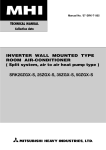
عHow to read the model name
Example: SRK 20 Z JX-S
Series code
Inveter type
Product capacity
Model name
SRK : Wall mounted type
SRF : Floor standing type
SRR : Ceiling concealed type
SRC : Outdoor unit
Example: FDTC 25 VD
Series code
Product capacity
Model name 䈀Ceiling cassette-4way compact type䈁
-
4-
'10 • SR-T-091
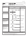
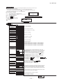
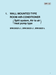
10 OUTLINE OF OPERATION CONTROL BY MICROCOMPUTER
10.1 Models SRK20 ~ 50ZJ-S
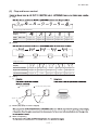
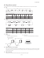
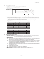
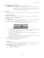
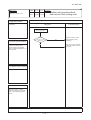
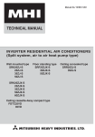
(1) Operation control function by remote controller
Operation section
FAN SPEED button
OPERATION MODE select button
Each time the button is pressed, the
display is switched over in turn.
Each time the button pressed, the
display is switched over in turn.
ON/OFF (luminous) button
HI POWER/ECONO button
Press to start operation, press again to
stop.
This button changes the HIGH POWER/
ECONOMY mode.
AIR FLOW (UP/DOWN) button
This button changes the air flow (up/down)
direction.
TEMPERATURE button
These buttons sets the indoor temperature.
(These buttons are used for setting the
current time and timer function as well.)
AIR FLOW (LEFT/RIGHT) button
This button changes the air flow (left/right)
direction.
ON TIMER button
This button selects ON TIMER operation.
3D AUTO button
This button sets 3D AUTO operation.
SLEEP button
OFF TIMER button
This button selects SLEEP operation.
This button selects OFF TIMER operation
ACL switch
CLEAN switch
This switch is for resetting microcomputer
and setting time.
This switch changes the CLEAN mode.
The above illustration shows all controls, but in practice
only the relevant parts are shown.
CANCEL button
This button cancels the ON timer, OFF
timer, and SLEEP operation.
ALLERGEN CLEAR button
This button selects ALLERGEN CLEAR
operation.
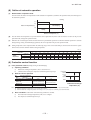
Unit display section
Remote control signal receiver
Unit ON/OFF button
This button can be used for turning on/off the unit when remote
control is not available.
RUN (HOT KEEP) light (green)
3D AUTO light (green)
Illuminates during operation.
Blinks when airflow stops due to thëHOT
KEEP̉and̈CLEAN operation̉.
HOT KEEP
ON
Illuminates during 3D AUTO operation.
HI POWER light (green)
1.5 sec.
Illuminates during HIGH POWER operation.
TIMER light (yellow)
OFF
0.5 sec.
CLEAN operation
ON
Illuminates during TIMER operation.
3 sec.
OFF
1 sec.
-
111 -
'10 • SR-T-091
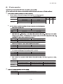
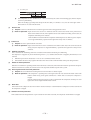
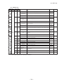
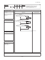
(2)ޓUnit ON/OFF button
(a) Operation
(b) Details of operation
Function Indoor temperature
Fan speed Flap/Louver Timer Switch
setting
operation mode
Cooling
Thermal dry
Heating
Unit ON/OFF button
(3)ޓAuto restart function
(a)
Jumper wire (JA1)
(b)
1)
2)
(4)ޓCustom cord switching procedure
Jumper wire (JA2)
(a) Modifying the indoor printed circuit board
(b) Modifying the wireless remote controller
1)
Cut
2)
-
112 -
'10 • SR-T-091
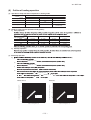
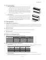
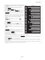
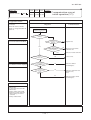
(5)ޓFlap and louver control
(a) Flap
(Flap stopped)
(Swing)
Angle of Flap from Horizontal
Remote controller
display
COOL , DRY, FAN
Approx. 10°
Approx. 25°
Approx. 40°
Approx. 50°
Approx. 60°
HEAT
Approx. 25°
Approx. 40°
Approx. 50°
Approx. 60°
Approx. 70°
(b) Louver
(Louver stopped)
(Swing)
(Spot)
(Wide)
Angle of Louver
Remote controller
display
Center installation
Left Approx. 50° Left Approx. 20°
Center
Right end installation Left Approx. 50° Left Approx. 45° Left Approx. 30°
Left end installation Left Approx. 20°
Center
Center
Right Approx. 20°
Right Approx. 30° Right Approx. 45° Right Approx. 50°
(c) Swing
1)
2)
In HEAT operation
Right Approx. 20° Right Approx. 50°
In COOL, DRY, FAN operation
Approx.
10°
Approx. 25°
Approx. 60°
Approx. 70°
(c) Memory flap (Flap or Louver stopped)
(d) When not operating
-
113 -
'10 • SR-T-091
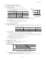
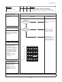
(6)ޓ3D auto operation
(a)
1)
Operation mode
At cooling
At heating
Air flow selection
AUTO
Indoor temp. – Setting temp. >5°C
Indoor temp. – Setting temp. <
= 5°C
HIGH POWER
AUTO
Setting temp. – Indoor temp. >5°C
Setting temp. – Indoor temp. <
= 5°C
HIGH POWER
AUTO
HI
MED
LO
HI
MED
LO
2)
a)
Cooling
Flap
Louver
Heating
Up/down Swing
Wide (Fixed)
Center (Fixed)
b)
c
Flap
Louver
Cooling
Heating
Horizontal blowing (Fixed)
Slant forwardl blowing (Fixed)
Left/right Swing
d
c)
Cooling
Flap
Louver
Heating
Up/down Swing
Center (Fixed)
d)
Flap
Louver
Cooling
Horizontal blowing (Fixed)
Heating
Slant forwardl blowing (Fixed)
Wide (Fixed)
e)
Operation mode
At cooling
At heating
Indoor temp. – Setting temp. <
= 2°C
The control in 4) continues.
Setting temp. – Indoor temp. <
= 2°C
The control in 4) continues.
Air flow direction contorol
2°C < Indoor temp. – Setting temp. <
= 5°C
Control returns to the control in 2).
2°C < Setting temp. – Indoor temp. <
= 5°C
Control returns to the control in 2).
(b)
Air flow selection
Flap
Louver
According to DRY operation.
Horizontal blowing (Fixed)
Wide (Fixed)
-
114 -
Indoor temp. – Setting temp. > 5°C
Control returns to the control in 1).
Setting temp. – Indoor temp. > 5°C
Control returns to the control in 1).
'10 • SR-T-091
(7)ޓTimer operation
(a) Comfortable timer setting (ON timer)
(b) Sleep timer operation
(c) OFF timer operation
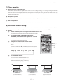
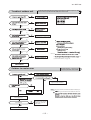
(8)ޓInstallation location setting
(a) Setting
1)
If the air conditioning unit is running, press the ON/OFF button to stop.
2)
Press the AIR FLOW
AIR FLOW
(UP/DOWN) button and the
(LEFT/RIGHT) button together for 5 seconds
or more.
3)
Setting the air-conditioning installation location.
, (Center Installation)
(Right End Installation)
Airf low range
(Left End Installation)
4)
(Left End Installation)
Airf low range
(Center Installation)
Press the ON/OFF button.
-
115 -
Airf low range
(Right End Installation)
'10 • SR-T-091
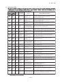
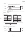
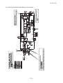
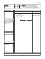
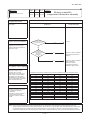
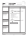
(9)ޓOutline of heating operation
(a)
Operation of major functional components in heating mode
Heating
Thermostat ON
Thermostat OFF
Failure
Compressor
ON
OFF
OFF
Indoor fan motor
ON
ON(HOT KEEP)
OFF
Outdoor fan motor
ON
OFF
(few minutes ON)
OFF
4-way valve
ON
ON
OFF
(3 minutes ON)
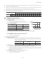
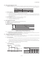
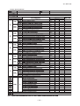
(b) Details of control at each operation mode (pattern)
1) Fuzzy operation
Model
SRK20ZJ-S
SRK25ZJ-S
SRK35ZJ-S
SRK50ZJ-S
Auto
30~115rps
30~115rps
30~115rps
23~106rps
HI
30~115rps
30~115rps
30~115rps
23~106rps
MED
30~66rps
30~72rps
30~76rps
23~78rps
LO
30~40rps
30~42rps
30~46rps
23~50rps
Fan speed
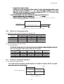
2) Hot keep operation
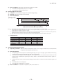
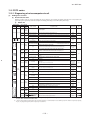
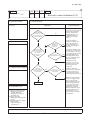
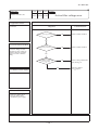
(c) Defrosting operation
1)
a)
(model 50 : 35)
b)
(model 50 : 35)
c)
−
d)
(model 50 : ≧ −2 )ޓ
≧
−
≦
(model 50 : ≧ −2 )ޓ
<
<−
−
Models 20㨪35
Model 50
0
Outdoor heat exchanger temperature (㷄)
Outdoor heat exchanger temperature (㷄)
0
-5
rt
io
at
er
n
em
t
Defrost operation
start
s
ro
ef
-15
-20
-20
p
to
sta
re
tu
ra
pe
-10
D
-15
-10
-5
0
5
10
Outdoor air temperature (㷄)
-5
-10
re
tu
ra
pe
m
e
tt
r
n
io
t
ra
sta
Defrost operation
start
pe
o
st
fro
-15
e
D
-20
-20
-15
-10
-5
0
Outdoor air temperature (㷄)
-
116 -
5
10
'10 • SR-T-091
e)
a) b) c)
e)
−
−
2)
a)
(model 50 : 10
b)
16 minutes and 50 seconds (model 50 : 18 minutes).
)
¡Defrast operation
Heating operation
Max. 16 minutes and 50 seconds
2~7 minutes ̪
(Mode 50 Nax.18 minutes)
Hot keep operation
̪Depends on an operation condition, the time can be longer than 7 minutes.
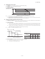
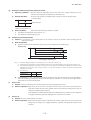
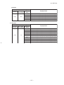
(10)ޓOutline of cooling operation
(a)ޓOperation of major functional components in Cooling mode
Cooling
Thermostat ON
Thermostat OFF
Failure
Compressor
ON
OFF
OFF
Indoor fan motor
ON
ON
OFF
Outdoor fan motor
ON
OFF
(few minutes ON)
OFF
(few minutes ON)
4-way valve
OFF
OFF
OFF
(b) Detail of control in each mode (Pattern)
1)
Fuzzy operation
Model
SRK20ZJ-S
SRK25ZJ-S
SRK35ZJ-S
SRK50ZJ-S
Auto
20~66rps
20~74rps
20~98rps
23~96rps
HI
20~66rps
20~74rps
20~98rps
23~96rps
MED
20~44rps
20~55rps
20~58rps
23~62rps
LO
20~30rps
20~34rps
20~38rps
23~38rps
Fan speed
(11)ޓOutline of automatic operation
(a) Determination of operation mode
Cooling
27.5
25.5
A
Indoor air temperature (˚C)
Dehumidifying
18.0
Heating
18
Outdoor air temperature (˚C)
-
117 -
30
'10 • SR-T-091
(b)
1) 2)
When both the indoor and the outdoor air temperatures are in the range “A”, cooling or heating is switched depending on
the difference between the setting temperature and the indoor air temperature.
3)
When the operation mode has been judged following the change of setting temperature with the remote controller, the hourly
judgment of operation mode is cancelled.
(c)
(d)
Signals of wireless remote controller (Display)
–6
–5
–4
–3
–2
±0
–1
+1
+2
+3
+4
+5
+6
Cooling
Setting
Dehumidifying
temperature
Heating
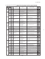
(12)ޓProtective control function
(a)
Frost prevention control
1)
Operating conditions
a)
compressor
command
speed
b)
2)
Detail of anti-frost operation
Item
Indoor heat exchanger
temperature
Lower limit of compressor command speed
5°C or lower
2.5°C or lower
(model 50 : 23 rps)
0 rps
Indoor fan
2.5
5
8
Indoor heat exchanger
temperature (ºC)
Outdoor fan
4-way valve
3)
Lower
limit
speed
Reset conditions:
a)
b)
(b) Cooling overload protective control
1)
Operating conditions:
more, or 47ºC or more (model 50 : 41ºC or more) with the compressor running, the lower limit
Model
SRK20~35ZJ-S
Item
Outdoor air temperature
41°C or more
Lower limit speed
2)
SRK50ZJ-S
29 rps
Detail of operation
a)
b) The lower limit of compressor command speed is set to 30 or 40 (model 50 : 29) rps and even if the calculated result
becomes lower than that after fuzzy calculation, the speed is kept to 30 or 40 (model 50 : 29) rps. However, when the
thermo becomes OFF, the speed is reduced to 0 rps.
-
118 -
'10 • SR-T-091
3)
Reset conditions:
a)
b)
(c)
Cooling high pressure control
1)
Purpose:
2)
Detector:
3)
Detail of operation:
(Example) Fuzzy
(3)
6rps
After lapse of 30 sec. or over
(1)
(3)
6rps
After lapse of 30 sec. or over
(1)
lower limit
(3)
After lapse of 30 sec. or over speed 30 (model 50 : 29) rps
0rps
58
53
63
Outdoor heat exchanger temperature (°C)
(d) Cooling low outdoor air temperature protective control
1)
Operating conditions:
2)
Detail of operation:
a)
than 50 <44> (30) rps, the speed is kept to 50 <44> (30) rps. However, when the thermo becomes OFF,the speed is
b)
(model 50 : 9ºC or 10ºC)
ON Upper limit 50 rps
Lower limit 50 rps
ON Upper limit 50 rps
Lower limit 44 rps
ON Upper limit 60 rps
Lower limit 30 rps
OFF
E
F
A
B
C
D
Outdoor air temperature.(°C)
(Model 50)
(Models 20 ~ 35)
Outdoor air temperature (˚C)
E
3)
F
A
B
C
Outdoor air temperature (˚C)
D
First time
First time
Since the
seconds times
Since the
second times
Reset conditions:
a)
b)
-
119 -
A
B
9
10
16
19
C
D
'10 • SR-T-091
(e)
Heating high pressure control
1)
Purpose:
2)
Detector:
3)
Detail of operation:
(Example) Fuzzy
4rps(1)
After lapse of 20 sec. or over(3)
(3)
4rps
After lapse of 20 sec. or over
After lapse of 20 sec. or over(3)
8rps(2)
(1)
8rps(2)
Note (1) Value in ( ) are for the model 50.
lower limit
speed 30(23) rps
0rps
A
C
B
Indoor heat exchanger temperature(°C)
D
Temperature list
Models 20 ~ 35
A
B
C
D
RPSmin < 50
50 <
= RPSmin < 91
91 <
= RPSmin < 97
97 <
= RPSmin < 100
100 <
= RPSmin < 115
115 <
= RPSmin
Model 50
A
B
C
D
RPSmin < 40
40 <
= RPSmin < 80
49
53
55
58
53
57
59
62
80 <
= RPSmin < 90
90 <
= RPSmin < 102
53 ~ 47
57 ~ 51
59 ~ 53
58
47 ~ 41
51 ~ 45
53 ~ 47
51
41
45
47
51
102 <
= RPSmin
(f) Heating overload protective control
1)
2)
Indoor unit side
a)
Operating conditions :
b)
Detail of operation :
c)
Reset conditions :
Outdoor unit side
• Models 20 ~ 35
a) Operating conditions : When the outdoor air temperature (TH2) is 22ºC or higher continues for 30 seconds while
the compressor command speed other than 0 rps.
b)
Detail of operation
i)
Taking the upper limit of compressor command speed range at 60 rps, if the output speed obtained with the fuzzy
calculation exceeds the upper limit, the upper limit value is maintained.
ii)
The lower limit of compressor command speed is set to 40 rps and even if the calculated result becomes lower than
that after fuzzy calculation, the speed is kept to 40 rps. However, when thethermo becomes OFF, the speed is
reduced to 0 prs.
iii)
rps.
iv)
-
120 -
'10 • SR-T-091
Protective
control
Normal operation
21
22
Outdoor air temperature(°C)
c)
.
Reset conditions:
• Model 50
a)
Operating conditions : When the outdoor air temperature (TH2) is 11ºC or higher continues for 30 seconds while
the compressor command speed other than 0 rps.
b)
Detail of operation
i)
Taking the upper limit of compressor command speed range at 78 rps, if the output speed obtained with the fuzzy
calculation exceeds the upper limit, the upper limit value is maintained.
ii)
The lower limit of compressor command speed is set to 30 rps and even if the calculated result becomes lower than
that after fuzzy calculation, the speed is kept to 30 rps. However, when thethermo becomes OFF, the speed is
reduced to 0 prs.
iii)
30 rps.
iv)
Item
Compressor command speed
Protective
control
NO1
Outdoor fan speed
Low limit
Upper limit
30 rps
78 rps
It depends on compressor command speed
30 rps
51 rps
2nd
NO2
Protective control ON2
Protective control ON1
Normal operation
10
11
19
20
Outdoor air temperature(°C)
c)
Reset conditions:
10
.
(g) Heating low outdoor temperature protective control
• Models 20 ~ 35
1) Operating conditions: 2) Detail of operation: Lower limit 45 rps
Lower limit 40 rps
Normal operation
-10
-8
-2
2
Outdoor air temperature(°C)
3)
Reset conditions:
a)
b)
-
121 -
'10 • SR-T-091
• Model 50
1)ޓOperating conditions: When the outdoor air temperature (TH2) is lower than 4ºC or higher continues for 30 seconds
while the compressor command speed is other than 0 rps.
2)ޓDetail of operation:
The lower limit compressor command speed is change as shown in the figure belo.
Lower limit 29 rps
Normal operation
4
6
Outdoor air temperature(°C)
3)ޓReset conditions:
When either of the following condition is satisfied.
a)ޓThe outdoor air temperature (TH2) becomes 6ºC.
b)ޓThe compressor command speed is 0 rps.
(h) Compressor overheat protection
1) Purpose:
2)
Detail of operation
a)
(Example) Fuzzy
90
Model
100
Discharge pipe temperature (˚C)
Item
Cooling
Heating
20 ~ 35
20 rps
30 rps
50
24 rps
29 rps
Lower limit speed
b)
(i)
(j)
Current safe
1)
Purpose:
2)
Detail of operation:
Current cut
1)
Purpose:
2)
Detail of operation:
-
122 -
110
'10 • SR-T-091
(k)
Outdoor unit failure
item 1), 2) is satisfied. Once the unit is stopped by this function, ti is not
1)
2)
(l)
Indoor fan motor protection
(m)
Serial signal transmission error protection
1) Purpose:
2) Detail of operation:
(n)
Rotor lock
(o)
Outdoor fan motor protection
(p)
Outdoor fan control at low outdoor temperature
Cooling
1)
Operating conditions:
2)
Detail of operation:
Outdoor fan
Outdoor temperature > 10˚C
Outdoor temperature <
= 10˚C
a)
b)
c)
3)
Reset conditions:
a)
b)
-
123 -
'10 • SR-T-091
Heating
1)
Operating conditions:
2)
Detail of operation:
3)
Reset conditions:
(model 50 : 0ºC)
(model 50 : 2ºC)
a)
b)
(q)
Refrigeration cycle system protection
1)
2)
3)
Starting conditions
a)
When 5 minutes have elapsed after the compressor ON or the completion of the defrost control
b)
c)
Other than the defrost control
When, after meeting the conditions of a) and b) above, the compressor speed, indoor air temperature (Th1) and indoor
heat exchanger temperature (Th2) have met the conditions in the following table for 5 minutes:
Operation mode
Compressor speed (N)
Indoor air temperature (Th1)
Indoor air temperature (Th1)/
Indoor heat exchanger temperature (Th2)
Cooling
50 <
=N
10 <
= Th1<
= 40
Th1−4<Th2
Heating
50 <
=N
0<
= Th1<
= 40
Th2<Th1+6
Contents of control
a)
When the conditions of 1) above are met, the compressor stops.
b)
Error stop occurs when the compressor has stopped 3 times within 60 minutes.
Resetting condition
When the compressor has been turned OFF
-
124 -
'10 • SR-T-091
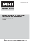
10.2 Models SRK20~60ZJX-S
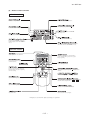
(1) Operation control function by remote controller
4 Operation section
FAN SPEED button
OPERATION MODE select button
Each time the button is pressed, the
display is switched over in turn.
Each time the button pressed, the
display is switched over in turn.
ON/OFF (luminous) button
HI POWER/ECONO button
Press to start operation, press again to
stop.
This button changes the HIGH POWER/
ECONOMY mode.
AIR FLOW (UP/DOWN) button
This button changes the air flow (up/down)
direction.
TEMPERATURE button
These buttons sets the indoor temperature.
(These buttons are used for setting the
current time and timer function as well.)
AIR FLOW (LEFT/RIGHT) button
This button changes the air flow (left/right)
direction.
ON TIMER button
This button selects ON TIMER operation.
3D AUTO button
This button sets 3D AUTO operation.
SLEEP button
OFF TIMER button
This button selects SLEEP operation.
This button selects OFF TIMER operation
ACL switch
CLEAN switch
This switch is for resetting microcomputer
and setting time.
This switch changes the CLEAN mode.
CANCEL button
The above illustration shows all controls, but in practice
only the relevant parts are shown.
ALLERGEN CLEAR button
This button cancels the ON timer, OFF
timer, and SLEEP operation.
This button selects ALLERGEN CLEAR
operation.
Unit indication section
Model All models
Unit ON/OFF button
This button can be used for turning on/off the unit when
remote controller is not available.
RUN (HOT KEEP) light (green/blue)
• Illuminates during operation.
green : except ECONO operation
blue : ECONO operation
• Blinks when airflow stops due to the ‘HOT
KEEP’ and ‘CLEAN operation’.
Remote controller signal receiver
1.5 sec.
HOT KEEP
ON
OFF
0.5 sec.
3 sec.
CLEAN operation
ON
OFF
1 sec.
3D AUTO light (green)
Illuminates during 3D AUTO operation
HI POWER light (green)
TIMER light (yellow)
Illuminates during HIGH POWER operation.
Illuminates during TIMER operation.
-
125 -
'10 • SR-T-091
(2) Unit ON/OFF button
When the remote controller batteries become weak, or if the remote controller is lost or malfunctioning, this button may be used to
turn the unit on and off.
(a)
Operation
Push the button once to place the unit in the automatic mode. Push it once more to turn the unit off.
(b)
Details of operation
The unit will go into the automatic mode in which it automatically determines, from indoor temperature (as detected by
sensor), whether to go into the cooling, thermal dry or heating modes.
Function Indoor temperature
Fan speed Flap/Louver Timer Switch
setting
operation mode
Cooling
About 24ºC
Thermal dry
About 25ºC
Heating
About 26ºC
Auto
Auto
Continuous
Unit ON/OFF button
(3) Auto restart function
(a)
Auto restart function records the operational status of the air-conditioner immediately prior to be switched off by a power cut,
and then automatically resumes operations after the power has been restored.
(b)
The following settings will be cancelled:
1)
Timer settings
2)
HIGH POWER operations
Jumper wire (J170)
Notes (1) Auto restart function is set at on when the air-conditioner is shipped from the factory. Consult with
your dealer if this function needs to be switched off.
(2) When power failure ocurrs, the timer setting is cancelled. Once power is resumed, reset the timer.
(3) If the jumper wire (J170) “AUTO RESTART” is cut, auto restart is disabled. (See the diagram at right)
Jumper wire (J171)
(4) Custom cord switching procedure
If two wireless remote controller are installed in one room, in order to prevent wrong operation due to mixed signals, please modify the printed circuit board in the indoor unit’s control
box and the remote controller using the following procedure. Be sure to modify both boards.
If only one board is modified, receiving (and operation) cannot be done.
(a)
Modifying the indoor printed circuit board
Take out the printed circuit board from the control box and cut off jumper wire (J171)
using wire cutters.
After cutting of the jumper wire, take measures to prevent contact with the other the
lead wires, etc.
(b)
Modifying the wireless remote controller
1)
Remove the battery.
2)
Cut the jumper wire shown in the figure at right.
Cut
-
126 -
'10 • SR-T-091
(5) Flap and louver control
Control the flap and louver by AIRFLOW (LEFT/RIGHT) button on the wireless remote controller.
(UP/DOWN) and
(a)
Flap
Each time when you press the AIRFLOW (UP/DOWN) button the mode changes as follows.
(Flap stopped)
(Swing)
Angle of Flap from Horizontal
Remote controller
display
(b)
COOL , DRY, FAN
Approx. 5°
Approx. 20°
Approx. 35°
Approx. 45°
Approx. 60°
HEAT
Approx. 20°
Approx. 35°
Approx. 45°
Approx. 60°
Approx. 75°
Louver
Each time when you press the AIRFLOW
(LEFT/RIGHT) button the mode changes as follows.
(Louver stopped)
(Swing)
(Spot)
(Wide)
Angle of Louver
Remote controller
display
Center installation
Left Approx. 50° Left Approx. 20°
Center
Right Approx. 20° Right Approx. 50°
Right end installation Left Approx. 50° Left Approx. 45° Left Approx. 30°
Left end installation Left Approx. 20°
(c)
Center
Center
Right Approx. 20°
Right Approx. 30° Right Approx. 45° Right Approx. 50°
Swing
1)
Swing flap
2)
Flap moves in upward and downward
Swing louver
Louver moves in left and right directions continuously.
directions continuously.
In HEAT operation
In COOL, DRY, FAN operation
Approx.
5°
Approx. 20°
Approx. 60°
Approx. 75°
(d)
Memory flap (Flap or Louver stopped)
When you press the AIRFLOW (UP/DOWN or LEFT/RIGHT) button once while the flap or louver is operating, it stops swinging
at the position. Since this angle is memorized in the microcomputer, the flap or louver will automatically be set at this angle when
the next operation is started.
(e)
When not operating
The flap returns to the position of air flow directly below, when operation has stopped.
-
127 -
'10 • SR-T-091
(6) 3D auto operation
Control the flap and louver by 3D AUTO button on the wireless remote controller.
Air flow selection and air flow direction are automatically controlled, allowing the entire indoor to efficiently conditioned.
(a)
During Cooling and Heating (Including auto cooling and heating)
1)
Air flow selection is determined according to indoor temperature and setting temperature.
Operation mode
At cooling
At heating
2)
Air flow selection
AUTO
Indoor temp. – Setting temp. >5°C
Indoor temp. – Setting temp. <
= 5°C
HIGH POWER
AUTO
Setting temp. – Indoor temp. >5°C
Setting temp. – Indoor temp. <
= 5°C
HIGH POWER
AUTO
HI
MED
LO
HI
MED
LO
Air flow direction is controlled according to the indoor temperature and setting temperature.
a)
When 3D auto operation starts
Cooling
Flap
Louver
b)
Heating
Up/down Swing
Wide (fixed)
Center (fixed)
When Indoor temp. – Setting temp. is <
= 5ºC during cooling and when Setting temp. – Indoor temp. is <
= 5ºC during
heating, the system switches to the following air flow direction control. After the louver swings left and right symmetrically for 3 cycles, control is switched to the control in c).
Flap
Louver
c)
Cooling
Heating
Horizontal blowing (Fixed)
Slant forwardl blowing (Fixed)
Left/right Swing
After the flap swings for 5 cycles, control is switched to the control in d).
Cooling
Flap
Louver
d)
For 5 minutes, the following air flow direction control is carried out.
Flap
Louver
e)
Heating
Up/down Swing
Center (Fixed)
Cooling
Horizontal blowing (Fixed)
Heating
Slant forwardl blowing (Fixed)
Wide (Fixed)
After 5 minutes have passed, the air flow direction is determined according to the indoor temperature and setting
temperature.
Operation mode
At cooling
At heating
(b)
Indoor temp. – Setting temp. <
= 2°C
The control in 4) continues.
Setting temp. – Indoor temp. <
= 2°C
The control in 4) continues.
Air flow direction contorol
2°C < Indoor temp. – Setting temp. <
= 5°C
Control returns to the control in 2).
2°C < Setting temp. – Indoor temp. <
= 5°C
Control returns to the control in 2).
During DRY Operation (including auto DRY operation)
Air flow selection
Flap
Louver
According to DRY operation.
Horizontal blowing (Fixed)
Wide (Fixed)
-
128 -
Indoor temp. – Setting temp. > 5°C
Control returns to the control in 1).
Setting temp. – Indoor temp. > 5°C
Control returns to the control in 1).
'10 • SR-T-091
(7) Timer operation
(a)
Comfortable timer setting (ON timer)
If the timer is set at ON when the operation select switch is set at the cooling or heating, or the cooling or heating in auto mode
operation is selected, the comfortable timer starts and determines the starting time of next operation based on the initial value
of 15 minutes and the relationship between the indoor temperature at the setting time (temperature of room temperature sensor)
and the setting temperature.
(b)
Sleep timer operation
Pressing the SLEEP button causes the temperature to be controlled with respect to the set temperature.
(c)
OFF timer operation
The Off timer can be set at a specific time (in 10-minute units) within a 24-hour period.
(8) Installation location setting
When the indoor unit is installed at the end of a room, control the air flow direction so that it is not toward the side walls. If you set
the remote controller installation position, keep it so that the air flow is within the range shown in the following figure.
(a)
Setting
1)
If the air conditioning unit is running, press the ON/OFF button to stop.
The installation location setting cannot be made while the unit is running.
2)
Press the AIR FLOW
(UP/DOWN) button and the
AIRFLOW
(LEFT/RIGHT) button together for 5 seconds
or more.
The installation location display illuminates.
3)
Setting the air-conditioning installation location.
Press the AIR FLOW
(LEFT/RIGHT) button and adjust to the desired
, location.
Each time the AIR FLOW
(LEFT/RIGHT) button is pressed, the
indicator is switched in the order of:
(Center Installation)
4)
(Right End Installation)
(Left End Installation)
Press the ON/OFF button.
The air-conditioner's installation location is set.
Press within 60 seconds of setting the installation location (while the
installation location setting display illuminates).
Airflow range
(Left End Installation)
Airflow range
(Center Installation)
-
129 -
Airflow range
(Right End Installation)
'10 • SR-T-091
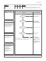
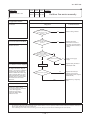
(9) Outline of heating operation
(a)
Operation of major functional components in heating mode
Heating
(b)
Thermostat ON
Thermostat OFF
Failure
Compressor
ON
OFF
OFF
Indoor fan motor
ON
ON(HOT KEEP)
OFF
Outdoor fan motor
ON
OFF
(few minutes ON)
OFF
4-way valve
ON
ON
OFF
(3 minutes ON)
Details of control at each operation mode (pattern)
1) Fuzzy operation
Deviation between the indoor temperature setting correction temperature and the return air temperature is calculated in
accordance with the fuzzy rule, and used for control of the air capacity and the compressor speed.
Model
SRK20ZJX-S
SRK25ZJX-S
SRK35ZJX-S
SRK50ZJX-S
SRK60ZJX-S
Auto
30~94rps
30~102rps
30~115rps
12~106rps
12~120rps
HI
30~94rps
30~102rps
30~115rps
12~106rps
12~120rps
MED
30~66rps
30~72rps
30~76rps
12~74rps
12~90rps
LO
30~40rps
30~42rps
30~46rps
12~42rps
12~58rps
Fan speed
When the defrosting, protection device, etc. is actuated, operation is performed in the corresponding mode.
2)
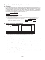
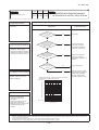
Defrosting operation
Starting conditions (Defrosting operation can be started only when all of the following conditions are met.)
a)
After start of heating operation
When it elapsed 45 (model 50, 60 : 35) minutes. (Accumulated compressor operation time)
b)
After end of defrosting operation
When it elapsed 45 (model 50, 60 : 35) minutes. (Accumulated compressor operation time)
c)
Outdoor heat exchanger sensor (TH1) temperature
When the temperature has been below −5ºC for 3 minutes continuously.
d)
The difference between the outdoor air sensor temperature and the outdoor heat exchanger sensor temperature
f The outdoor air temperature ≧ 0ºC (model 50, 60 : ≧ −2ºC) : 7ºC or higher
f −15ºC ≦ The outdoor air temperature < 0ºC (model 50, 60 : < −2ºC) : 4/15 × The outdoor air temperature
+ 7ºC or higher
f The outdoor air temperature < −15ºC : −5ºC or higher
Models 20㨪35
Models 50, 60
0
0
Outdoor heat exchanger temperature (㷄)
1)
Outdoor heat exchanger temperature (㷄)
(c)
Hot keep operation
If the hot keep operation is selected during the heating operation, the indoor blower is controlled based on the temperature
of the indoor heat exchanger (Th2) to prevent blowing of cool wind.
-5
rt
em
t
sta
Defrost operation
start
s
ro
ef
-15
-20
-20
n
io
at
er
p
to
re
tu
ra
pe
-10
D
-15
-10
-5
0
5
10
Outdoor air temperature (㷄)
-5
-10
rt
n
io
t
ra
re
tu
ra
pe
m
te
sta
Defrost operation
start
pe
-15
o
st
ro
ef
D
-20
-20
-15
-10
-5
0
Outdoor air temperature (㷄)
-
130 -
5
10
'10 • SR-T-091
e)
During continuous compressor operation
In addition, when the speed command from the indoor controller of the indoor unit during heating operation has counted
0 rps 10 times or more and all conditions of a), b), c) and e) above and the outdoor air temperature is 3ºC or less are
satisfied (note that when the temperature for outdoor heat exchanger sensor (TH1) is −5ºC or less: 62 rps or more,
2)
−4ºC or less: less than 62 rps), defrost operation is started.
Ending conditions (Operation returns to the heating cycle when either one of the following is met.)
a)
Outdoor heat exchanger sensor (TH1) temperature: 13ºC (model 50, 60 : 10ºC) or higher
b)
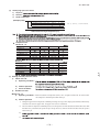
Continued operation time of defrosting → For more than 16 minutes and 50 seconds (model 50, 60 : 18 minutes).
¡Defrast operation
Heating operation
Max. 16 minutes and 50 seconds
2~7 minutes ̪
(Mode 50, 60 Nax.18 minutes)
Hot keep operation
̪Depends on an operation condition, the time can be longer than 7 minutes.
(10) Outline of cooling operation
(a)
Operation of major functional components in Cooling mode
Cooling
(b)
Thermostat ON
Thermostat OFF
Failure
Compressor
ON
OFF
OFF
Indoor fan motor
ON
ON
OFF
Outdoor fan motor
ON
OFF
(few minutes ON)
OFF
(few minutes ON)
4-way valve
OFF
OFF
OFF
Detail of control in each mode (Pattern)
1)
Fuzzy operation
During the fuzzy operation, the air flow and the compressor speed are controlled by calculating the difference between the
indoor temperature setting correction temperature and the return air temperature.
Model
SRK20ZJX-S
SRK25ZJX-S
SRK35ZJX-S
SRK50ZJX-S
SRK60ZJX-S
Auto
20~65rps
20~74rps
20~86rps
12~86rps
12~110rps
HI
20~65rps
20~74rps
20~86rps
12~86rps
12~110rps
MED
20~44rps
20~55rps
20~58rps
12~62rps
12~86rps
LO
20~30rps
20~34rps
20~38rps
12~34rps
12~48rps
Fan speed
(11) Outline of automatic operation
(a)
Determination of operation mode
The unit checks the indoor air temperature and the outdoor air temperature, determines the operation mode, and then begins in
the automatic operation.
Cooling
27.5
25.5
Dehumidifying
Indoor air temperature (˚C)
19.5
Heating
18
Outdoor air temperature (˚C)
-
131 -
30
'10 • SR-T-091
(b)
The unit checks the temperature every hour after the start of operation and, if the result of check is not same as the previous
operation mode, changes the operation mode.
(c)
When the unit is started again within one hour after the stop of automatic operation or when the automatic operation is selected
during heating, cooling or dehumidifying operation, the unit is operated in the previous operation mode.
(d)
Setting temperature can be adjusted within the following range. There is the relationship as shown below between the signals
of the wireless remote controller and the setting temperature.
Unit : ºC
Signals of wireless remote controller (Display)
Setting
temperature
–6
–5
–4
–3
–2
–1
±0
+1
+2
+3
+4
+5
+6
Cooling
18
19
20
21
22
23
24
25
26
27
28
29
30
Dehumidifying
19
20
21
22
23
24
25
26
27
28
29
30
31
Heating
20
21
22
23
24
25
26
27
28
29
30
31
32
(12) Protective control function
(a)
Frost prevention control (During cooling or dehumidifying)
1)
2)
Operating conditions
a)
Indoor heat exchanger temperature (Th2) is lower than 5ºC.
b)
5 minutes after reaching the compressor command speed except 0 rps.
Detail of anti-frost operation
compressor
command
speed
5°C or lower
2.5°C or lower
Lower
limit
speed
Lower limit of compressor command speed
22 rps (model 50, 60 : 25 rps)
0 rps
0 rps
Indoor fan
Protects the fan tap just before
Depends on operation mode
frost prevention control
Outdoor fan
Depends on command speed
4-way valve
OFF
Item
Indoor heat exchanger
temperature
2.5
5
8
Indoor heat exchanger
temperature (ºC)
Depends on stop mode
Notes (1) When the indoor heat exchanger temperature is in the range of 2.5~5ºC, the speed is reduced by 4 rps at each 20 seconds.
(2) When the temperature is lower than 2.5ºC, the compressor is stopped.
(3) When the indoor heat exchanger temperature is in the range of 5~8ºC, the compressor command speed is been maintained.
3)
Reset conditions: When either of the following condition is satisfied.
a) The indoor heat exchanger temperature (Th2) is 8ºC or higher.
b)
(b)
The compressor command speed is 0 rps.
Cooling overload protective control
1)
Operating conditions: When the outdoor air temperature (TH2) has become continuously for 30 seconds at 41ºC or
more, or 47ºC or more (Models 50, 60: 41ºC or more) with the compressor running, the lower
limit speed of compressor is brought up.
Model
SRK20~35ZJX-S
Item
Outdoor air temperature
Lower limit speed
2)
SRK50, 60ZJX-S
41°C or more
47°C or more
41°C or more
30 rps
40 rps
30 rps
Detail of operation
a)
The outdoor fan is stepped up by 3 speed step. (Upper limit 7th (models 50, 60 : 8th) speed.)
b)
The lower limit of compressor command speed is set to 30 or 40 (models 50, 60 : 30) rps and even if the calculated result
becomes lower than that after fuzzy calculation, the speed is kept to 30 or 40 (models 50, 60 : 30) rps. However, when the
thermo becomes OFF, the speed is reduced to 0 rps.
3)
Reset conditions: When either of the following condition is satisfied.
a)
The outdoor air temperature is lower than 40ºC or 46ºC.
b)
The compressor command speed is 0 rps.
-
132 -
'10 • SR-T-091
(c)
Cooling high pressure control
1)
Purpose: Prevents anomalous high pressure operation during cooling.
2)
Detector: Outdoor heat exchanger sensor (TH1)
3)
Detail of operation:
(Example) Fuzzy
(3)
6rps
After lapse of 30 sec. or over
(1)
6rps(1)
After lapse of 30 sec. or over(3)
lower limit
speed 30 rps
After lapse of 30 sec. or over(3)
0rps
58
53
63
Outdoor heat exchanger temperature (°C)
Notes (1) When the outdoor heat exchanger temperature is in the range of 58~63ºC, the speed is reduced by 6 rps at each 30 seconds.
(2) When the temperature is 63ºC or higher, the compressor is stopped.
(3) When the outdoor heat exchanger temperature is in the range of 53~58ºC, if the compressor command speed is been maintained and the operation has
continued for more than 30 seconds at the same speed, it returns to the normal cooling operation.
(d)
Cooling low outdoor temperature protective control
1)
Operating conditions: When the outdoor air temperature (TH2) is 22ºC or lower continues for 20 seconds while the
2)
Detail of operation:
compressor command speed is other than 0 rps.
a)
The lower limit of the compressor command speed is set to 44 (30) rps and even if the speed becomes lower than
44 (30) rps, the speed is kept to 44 (30) rps. However, when the thermo becomes OFF, the speed is reduced to 0 rps.
b)
The upper limit of the compressor command speed is set to 50 (60) rps and even if the calculated result becomes
higher than that after fuzzy calculation, the speed is kept to 50 (60) rps.
Note
(1) Values in ( ) are for outdoor air temperature is 22ºC or 25ºC
ON Upper limit 50 rps
Lower limit 44 rps
ON
Upper limit 60 rps
Lower limit 30 rps
f Values of A, B, C, D
Outdoor air temp. (˚C)
OFF
A
3)
B
C
D
Outdoor air temperature (°C)
A
B
C
D
First time
0
3
22
25
Since the seconds
times
7
10
25
28
Reset conditions: When either of the following condition is satisfied
a)
The outdoor air temperature (TH2) is D ºC or higher.
b)
The compressor command speed is 0 rps.
-
133 -
'10 • SR-T-091
(e)
Heating high pressure control
1)
Purpose: Prevents anomalous high pressure operation during heating.
2)
Detector: Indoor heat exchanger sensor (Th2)
3)
Detail of operation:
(Example) Fuzzy
After lapse of 20 sec. or over(3)
4rps
(1)
4rps(1)
(3)
After lapse of 20 sec. or over
(3)
After lapse of 20 sec. or over
8rps
(2)
8rps(2)
lower limit
speed 30(model 50, 60:35)rps
0rps
C
B
A
D
Indoor heat exchanger temperature(°C)
Notes (1) When the indoor heat exchanger temperature is in the range of B~C ºC, the speed is reduced by 4 rps at each 20 seconds.
(2) When the indoor heat exchanger temperature is in the range of C~D ºC, the speed is reduced by 8 rps at each 20 seconds. When the temperature is D ºC
or higher continues for 1 minute, the compressor is stopped.
(3) When the indoor heat exchanger temperature is in the range of A~B ºC, if the compressor command speed is been maintained and the operation has continued for more than 20 seconds at the same speed, it returns to the normal heating operation.
(4) Indoor blower retains the fan tap when it enters in the high pressure control. Outdoor blower is operated in accordance with the speed.
f
Temperature list
Models 20~35
A
B
C
Unit : ºC
D
58
48
53
55
48.5
56
58
61
95 <
= RPSmin < 97
97 <
= RPSmin < 104
48.5
56 ~ 55.5
58
61
48.5
55.5 ~ 51.5
58 ~ 53.5
61
104 <
= RPSmin < 115
115 <
= RPSmin
48.5 ~ 42.1
51.5 ~ 44
53.5 ~ 47.3
61
42.1
44
47.3
61
RPSmin < 50
50 <
= RPSmin < 95
Note (1) RPSmin: The lower one between the outdoor speed and the compressor command speed
Models 50, 60
A
RPSmin < 88
88 <
= RPSmin < 108
108 <
= RPSmin
B
Unit : ºC
D
C
48.5
56
58
61
44
51.5
53.5
56.5
39
46.5
48.5
51.5
Note (1) RPSmin: The lower one between the outdoor speed and the compressor command speed
(f)
Heating overload protective control
1)
Operating conditions: When the outdoor air temperature (TH2) is 22ºC (model 50, 60 : 17ºC) or higher continues for
2)
Detail of operation:
30 seconds while the compressor command speed other than 0 rps.
a)
Taking the upper limit of compressor command speed range at 60 rps (model 50, 60 : 50 rps), if the output speed
obtained with the fuzzy calculation exceeds the upper limit, the upper limit value is maintained.
b)
The lower limit of compressor command speed is set to 40 rps (model 50, 60 : 35 rps) and even if the calculated
result becomes lower than that after fuzzy calculation, the speed is kept to 40 rps (model 50, 60 : 35 rps). However,
when the thermo becomes OFF, the speed is reduced to 0 prs.
c)
Inching prevention control is activated and inching prevention control is carried out with the minimum speed set at
40 rps (model 50, 60 : 35 rps).
3)
d)
The outdoor fan is set on 2nd speed.
e)
The indoor fan is stepped up by 1 speed step. (Upper limit 8th speed)
Reset conditions: The outdoor air temperature (TH2) is lower than 21ºC (model 50, 60 : 16ºC).
-
134 -
'10 • SR-T-091
(g)
Heating low outdoor temperature protective control
• Model 20~35
1)
Operating conditions: When the outdoor air temperature (TH2) is lower than -10ºC or higher continues for 30 seconds while the compressor command speed is other than 0 rps.
2)
Detail of operation: The lower limit compressor command speed is change as shown in the figure below.
Lower limit 45 rps
Normal operation
-10
-7
Outdoor air temperature (°C)
3)
When either of the following condition is satisfied.
Reset conditions:
a)
The outdoor air temperature (TH2) becomes -7ºC.
b)
The compressor command speed is 0 rps.
• Model 50, 60
1)
Operating conditions: When the outdoor air temperature (TH2) is lower than 4ºC or 13ºC or higher continues for 30
seconds while the compressor command speed is other than 0 rps.
2)
The lower limit compressor command speed is change as shown in the figure below.
Detail of operation:
Lower limit 45 rps
Lower limit 32 rps
Normal operation
-8
-6
4
6
11
13
Outdoor air temperature (°C)
3)
(h)
Reset conditions:
When either of the following condition is satisfied.
a)
The outdoor air temperature (TH2) becomes 6ºC ~ 11ºC.
b)
The compressor command speed is 0 rps.
Compressor overheat protection
1) Purpose: It is designed to prevent deterioration of oil, burnout of motor coil and other trouble resulting from the
compressor overheat.
2) Detail of operation
a) Speeds are controlled with temperature detected by the sensor mounted on the discharge pipe.
(Example) Fuzzy
4 rps (1)
After lapse of 3 min. or over (3)
After lapse of 3 min. or over
(3)
After lapse of 3 min. or over
(3)
4 rps
Lower limit (4)
0 rps
90 (95)
100 (105)
Discharge pipe temperature (˚C)
110 (115)
• Value in ( ) are for the
model 50, 60.
Notes (1) When the discharge pipe temperature is in the range of 100~110ºC (model 50, 60 : 105~115ºC), the speed is reduced by 4 rps.
(2) When the discharge pipe temperature is raised and continues operation for 20 seconds without changing, then the speed is reduced again by 4 rps.
(3) If the discharge pipe temperature is in the range of 90~100ºC (model 50, 60 : 95~105ºC) even when the compressor command speed is maintained
for 3 minutes when the temperature is in the range of 90~100ºC (model 50, 60 : 95~105ºC), the speed is raised by 1 rps and kept at that speed for
3 minutes. This process is repeated until the command speed is reached.
-
135 -
'10 • SR-T-091
(4) Lower limit speed
Item
Model
Lower Limit Speed
b)
(i)
Cooling
Heating
20~35
20 rps
30 rps
50, 60
25 rps
32 rps
If the temperature of 110ºC (models 50, 60 : 115ºC) is detected by the sensor on the discharge pipe, then the compressor will stop immediately.
When the discharge pipe temperature drops and the time delay of 3 minutes is over, the unit starts again within 1
hour but there is no start at the third time.
Current safe
1)
Purpose: Current is controlled not to exceed the upper limit of the setting operation current.
2)
Detail of operation: Input current to the converter is monitored with the current sensor fixed on the printed circuit
board of the outdoor unit and, if the operation current value reaches the limiting current value, the
compressor command speed is reduced.
If the mechanism is actuated when the compressor command speed is less than 30 rps, the compressor is stopped immediately. Operation starts again after a delay time of 3 minutes.
(j)
Current cut
1)
Purpose: Inverter is protected from overcurrent.
2)
Detail of operation: Output current from the inverter is monitored with a shunt resistor and, if the current exceeds the
setting value, the compressor is stopped immediately. Operation starts again after a delay time of
3 minutes.
(k)
Outdoor unit failure
This is a function for determining when there is trouble with the outdoor unit during air conditioning.
The compressor is stopped if any one of the following in item 1), 2) is satisfied. Once the unit is stopped by this function, it is not
restarted.
1) When the input current is measured at 1 A or less for 3 continuous minutes or more.
2) If the outdoor unit sends a 0 rps signal to the indoor unit 3 times or more within 20 minutes of the power being turned on.
(l)
Indoor fan motor protection
When the air conditioner is operating and the indoor fan motor is turned ON, if the indoor fan motor has operated at 300 rpm or
under for more than 30 seconds, the unit enters first in the stop mode and then stops the entire system.
(m) Serial signal transmission error protection
1) Purpose: Prevents malfunction resulting from error on the indoor ↔ outdoor signals.
2) Detail of operation: If the compressor is operating and a serial signal cannot be received from the indoor control with
outdoor control having serial signals continues for 7 minute and 35 seconds, the compressor is
stopped.
After the compressor has been stopped, it will be restarted after the compressor start delay if a serial
signal can be received again from the indoor control.
(n)
Rotor lock
If the motor for the compressor does not turn after it has been started, it is determined that a compressor lock has occurred and
the compressor is stopped.
(o) Outdoor fan motor protection
If the outdoor fan motor has operated at 75 rpm or under for more than 30 seconds, the compressor and fan motor are stopped.
-
136 -
'10 • SR-T-091
(p)
Outdoor fan control at low outdoor temperature
U
Cooling
1)
Operating conditions: When the outdoor air temperature (TH2) is 22ºC or lower continues for 30 seconds while the
2)
Detail of operation: After the outdoor fan operates at A speed for 60 seconds; the corresponding outdoor heat
compressor command speed is other than 0 rps.
exchanger temperature shall implement the following controls.
f Value of A
Outdoor fan
a)
Outdoor temperature > 10˚C
2nd speed
Outdoor temperature <
= 10˚C
1st speed
Outdoor heat exchanger temperature <
= 21ºC
After the outdoor fan speed drops (down) to 1 speed for 60 seconds; if the outdoor heat exchanger temperature is
b)
lower than 21ºC, gradually reduce the outdoor fan speed by 1 speed. (Lower limit 1st speed)
21ºC < Outdoor heat exchanger temperature <
= 38ºC
After the outdoor fan speed maintains at A speed for 20 seconds; if the outdoor heat exchanger temperature is 21ºC~
38ºC, maintain outdoor fan speed.
c)
Outdoor heat exchanger tempeature > 38ºC
After the outdoor fan speed rises (up) to 1 speed for 60 seconds; if the outdoor heat exchanger temperature is higher
than 38ºC, gradually increase outdoor fan speed by 1 speed. (Upper limit 3rd speed)
3)
Reset conditions: When either of the following conditions is satisfied
a)
The outdoor air temperature (TH2) is 25ºC or higher.
b)
The compressor command speed is 0 rps.
U
Heating
1)
Operating conditions: When the outdoor air temperature (TH2) is 4ºC or lower continues for 30 seconds while the
2)
Detail of operation: The outdoor fan is stepped up by 2 speed step at each 20 seconds. (Upper limit 8th speed)
3)
Reset conditions: When either of the following conditions is satisfied
compressor command speed is other than 0 rps.
(q)
a)
The outdoor air temperature (TH2) is 6ºC or higher.
b)
The compressor command speed is 0 rps.
Refrigeration cycle system protection
1)
Starting conditions
a)
When 5 minutes have elapsed after the compressor ON or the completion of the defrost control
b)
Other than the defrost control
c)
When, after meeting the conditions of a) and b) above, the compressor speed, indoor air temperature (Th1) and indoor heat exchanger temperature (Th2) have met the conditions in the following table for 5 minutes:
Operation mode
Compressor speed (N)
Indoor air temperature (Th1)
Indoor air temperature (Th1)/
Indoor heat exchanger temperature (Th2)
Cooling
50(40) <
=N
10 <
= Th1<
= 40
Th1−4<Th2
Heating
50(40) <
=N
0<
= Th1<
= 40
Th2<Th1+6
Note (1) Value in ( ) are for the model 50, 60.
2)
3)
Contents of control
a)
When the conditions of 1) above are met, the compressor stops.
b)
Error stop occurs when the compressor has stopped 3 times within 60 minutes.
Resetting condition
When the compressor has been turned OFF
-
137 -
'10 • SR-T-091
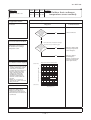
10.3 Models SRF25~50ZJX-S
(1) Operation control function by remote controller
Operation section
Model All models
FAN SPEED button
OPERATION MODE select button
Each time the button is pressed, the
display is switched over in turn.
Each time the button pressed, the
display is switched over in turn.
HI POWER/ECONO button
ON/OFF (luminous) button
This button changes the HIGH POWER/
ECONOMY mode.
Press to start operation, press again to
stop.
AIR FLOW (UP/DOWN) button
This button changes the air flow (up/down)
direction.
TEMPERATURE button
These buttons set the indoor temperature.
(These buttons are used for setting the
current time and timer function as well.)
ON TIMER button
This button selects ON TIMER operation.
SLEEP button
OFF TIMER button
This button selects SLEEP operation.
This button selects OFF TIMER operation.
ACL switch
CLEAN switch
This switch selects the CLEAN mode.
This switch is for resetting microcomputer
and setting time.
•
CANCEL button
The above illustration shows all controls, but in practice
only the relevant parts are shown.
This button cancels the ON timer, OFF
timer, and SLEEP operation.
Unit display section
Model All models
Unit ON/OFF button
RUN (HOT KEEP) light (green)
• Illuminates during operation.
This button can be used for turning on/off the unit when remote
controller is not available.
• Blinks when airflow stops due to the ‘HOT
KEEP’ and ‘CLEAN operation’.
1.5 sec.
HI POWER Light (green)
HOT KEEP
Illuminates during HIGH POWER operation.
ON
OFF
AIR SELECTION button
0.5 sec.
Use this button to switch between the combination of upper and
lower air outlets and upper air outlet.
3 sec.
AIR OUTLET SELECTION light (green)
CLEAN operation
ON
OFF
Illuminates during upper air outlet operation.
1 sec.
Remote controller signal receiver
TIMER light (yellow)
Illuminates during TIMER operation.
ECONO light (green)
Illuminates during ECONOMY operation.
-
138 -
'10 • SR-T-091
(2) Unit ON/OFF button
When the remote controller batteries become weak, or if the remote controller is lost or malfunctioning, this button may be used to
turn the unit on and off.
(a) Operation
Push the button once to place the unit in the automatic mode. Push it once more to turn the unit off.
(b) Details of operation
The unit will go into the automatic mode in which it automatically determines, from indoor temperature (as detected by sensor), whether to go into the cooling, thermal dry or heating modes.
Unit ON/OFF button
Function Indoor temperature
Fan speed Flap/Louver Timer Switch
setting
operation mode
Cooling
About 24ºC
Thermal dry
About 25ºC
Heating
About 26ºC
Auto
Auto
Continuous
(3) Auto restart function
(a)
Auto restart function records the operational status of the air-conditioner immediately prior to be switched off by a power cut,
and then automatically resumes operations after the power has been restored.
(b)
The following settings will be cancelled:
1)
Timer settings
2)
HIGH POWER operations
Jumper wire (J170)
Notes (1) Auto restart function is set at on when the air-conditioner is shipped from the factory. Consult with
your dealer if this function needs to be switched off.
(2) When power failure ocurrs, the timer setting is cancelled. Once power is resumed, reset the timer.
(3) If the jumper wire (J170) “AUTO RESTART” is cut, auto restart is disabled. (See the diagram at right)
Jumper wire (J171)
(4) Custom cord switching procedure
If two wireless remote controller are installed in one room, in order to prevent wrong operation due to mixed signals, please modify the printed circuit board in the indoor unit’s control
box and the remote controller using the following procedure. Be sure to modify both boards.
If only one board is modified, receiving (and operation) cannot be done.
(a)
Modifying the indoor printed circuit board
Take out the printed circuit board from the control box and cut off jumper wire (J171)
using wire cutters.
After cutting of the jumper wire, take measures to prevent contact with the other the
lead wires, etc.
(b)
Modifying the wireless remote controller
1)
Remove the battery.
2)
Cut the jumper wire shown in the figure at right.
Cut
-
139 -
'10 • SR-T-091
(5) Flap control
Control the flap by AIRFLOW (UP/DOWN) button on the wireless remote controller.
(a)
Flap
Each time when you press the AIRFLOW (UP/DOWN) button the mode changes as follows.
(Flap stopped)
(Swing)
Angle of Flap from Horizontal
Remote controller
display
(b)
COOL , DRY, FAN
Approx. 60°
Approx. 50°
Approx. 38°
HEAT
Approx. 44°
Approx. 32°
Approx. 21.5° Approx. 12°
Approx. 21.5° Approx. 12°
Approx. 5°
Swing
1)
Swing flap
Flap moves in upward and downward directions continuously.
In HEAT operation
In COOL, DRY, FAN operation
Approx.60°
Approx.44°
Approx.12°
Approx.5°
(c) Memory flap (Flap stopped)
When you press the AIRFLOW button once while the flap is operating, it stops swinging at the position. Since this angle is memorized in the microcomputer, the flap will automatically be set at this angle when the next operation is started.
(d)
When not operating
The flap returns to the position of air flow directly below, when operation has stopped.
(6) Air outlet selection
(a)
AIR SELECTION button can switch between the combination of upper and lower air outlets and upper air
outlet. Not operable while the air conditioner is OFF.
1) Each time the AIR SELECTION button is pressed. The combination of the
upper and lower air outlets and the upper air outlet can be switched.
2) When the upper air outlet is selected, AIR OUTLET SELECTION light on
the unit display area will light green.
Upper and lower air outlets
AIR OUTLET SELECTION
light : OFF
Upper air outlet
AIR OUTLET SELECTION
light : ON
AIR SELECTION button
-
140 -
'10 • SR-T-091
(b)
Auto air outlet selection
1) COOL, DRY operation
a) In case both lower and upper outlets operation is selected in Cooling or Dry
operation, both outlets will be kept for sixty minutes after the start or until
indoor temperature is below the setting point. And then the air outlet will change
to the upper outlet. That state will be maintained until switch is turned off.
b) In case both outlets operation with Auto fan speed mode is selected, the upper
outlet will be kept for ten minutes after the start or until indoor temperature is
close to reaching the setting point . And then the air outlet will change to both
outlets in order to spread comfort air to every corner.
2)
HEAT operation
a) In case both lower and upper outlets operation with Auto fan speed mode is
selected, the lower outlet will be kept for twenty minutes after the start or until
indoor temperature is close to reaching the setting point . And then the air outlet will
change to both outlets. That state will be maintained until the switch is turned off.
b) Automatic adjustment of lower air outlet direction prevents stirring up of
warm air and keeps optimum comfort at floor level.
(7) Timer operation
(a)
Comfortable timer setting (ON timer)
If the timer is set at ON when the operation select switch is set at the cooling or heating, or the cooling or heating in auto mode
operation is selected, the comfortable timer starts and determines the starting time of next operation based on the initial value
of 15 minutes and the relationship between the indoor temperature at the setting time (temperature of room temperature sensor)
and the setting temperature.
(b)
Sleep timer operation
Pressing the SLEEP button causes the temperature to be controlled with respect to the set temperature.
(c)
OFF timer operation
The Off timer can be set at a specific time (in 10-minute units) within a 24-hour period.
(8) Outline of heating operation
(a)
Operation of major functional components in heating mode
Heating
(b)
Thermostat ON
Thermostat OFF
Failure
Compressor
ON
OFF
OFF
Indoor fan motor
ON
ON(HOT KEEP)
OFF
Outdoor fan motor
ON
OFF
(few minutes ON)
OFF
4-way valve
ON
ON
OFF
(3 minutes ON)
Details of control at each operation mode (pattern)
1) Fuzzy operation
Deviation between the indoor temperature setting correction temperature and the return air temperature is calculated in
accordance with the fuzzy rule, and used for control of the air capacity and the compressor speed.
Model
SRF25ZJX-S
SRF35ZJX-S
SRF50ZJX-S
Auto
30~102rps
30~115rps
12~110rps
HI
30~102rps
30~115rps
12~110rps
MED
30~76rps
30~106rps
12~80rps
LO
30~58rps
30~80rps
12~60rps
Fan speed
When the defrosting, protection device, etc. is actuated, operation is performed in the corresponding mode.
2)
Hot keep operation
If the hot keep operation is selected during the heating operation, the indoor blower is controlled based on the temperature
of the indoor heat exchanger (Th2) to prevent blowing of cool wind.
-
141 -
'10 • SR-T-091
Defrosting operation
1)
Starting conditions (Defrosting operation can be started only when all of the following conditions are met.)
a)
After start of heating operation
When it elapsed 45 (model 50 : 35) minutes. (Accumulated compressor operation time)
b)
After end of defrosting operation
When it elapsed 45 (model 50 : 35) minutes. (Accumulated compressor operation time)
c)
Outdoor heat exchanger sensor (TH1) temperature
When the temperature has been below –5ºC for 3 minutes continuously.
d)
The difference between the outdoor air sensor temperature and the outdoor heat exchanger sensor temperature
f The outdoor air temperature ≧ 0°C ( model 50 : ≧ -2°C ) : 7°C or higher
f -15°C ≦ The outdoor air temperature < 0°C (model 50 : < -2°C) : 4/15 × The outdoor air temperature + 7°C or
higher
f The outdoor air temperature < -15°C : -5°C or higher
20㨪35
Models 25,35
50, 60
Models 50
0
Outdoor heat exchanger temperature (㷄)
0
Outdoor heat exchanger temperature (㷄)
(c)
-5
pe
re
tu
ra
-10
m
e
tt
ar
n
tio
st
ra
st
-15
-20
-20
e
op
Defrost operation
start
fro
e
D
-15
-10
-5
0
5
10
-5
-10
rt
n
t
sta
Defrost operation
start
er
-15
s
ro
ef
p
to
D
-20
-20
Outdoor air temperature (㷄)
e)
io
at
re
tu
ra
pe
em
-15
-10
-5
0
5
10
Outdoor air temperature (㷄)
During continuous compressor operation
In addition, when the speed command from the indoor controller of the indoor unit during heating operation has
counted 0 rps 10 times or more and all conditions of a), b), c) and e) above and the outdoor air temperature is 3°C or
less are satisfied (note that when the temperature for outdoor heat exchanger sensor (TH1) is -5°C or less: 62 rps or
more, -4°C or less: less than 62 rps), defrost operation is started.
2)
Ending conditions (Operation returns to the heating cycle when either one of the following is met.)
a)
Outdoor heat exchanger sensor (TH1) temperature: 13ºC (model 50 : 10°C) or higher
b)
Continued operation time of defrosting → For more than 16 minutes and 50 seconds (model 50 : 18 minutes).
¡Defrast operation
Heating operation
Max. 16 minutes and 50 seconds
2~7 minutes ̪
(Mode 50 Nax.18 minutes)
Hot keep operation
̪Depends on an operation condition, the time can be longer than 7 minutes.
-
142 -
'10 • SR-T-091
(9) Outline of cooling operation
(a)
Operation of major functional components in Cooling mode
Cooling
(b)
Thermostat ON
Thermostat OFF
Failure
Compressor
ON
OFF
OFF
Indoor fan motor
ON
ON
OFF
Outdoor fan motor
ON
OFF
(few minutes ON)
OFF
(few minutes ON)
4-way valve
OFF
OFF
OFF
Detail of control in each mode (Pattern)
1)
Fuzzy operation
During the fuzzy operation, the air flow and the compressor speed are controlled by calculating the difference between
the indoor temperature setting correction temperature and the retum air temperature.
Model
SRF25ZJX-S
SRF35ZJX-S
SRF50ZJX-S
Auto
20~72rps
20~104rps
12~86rps
HI
20~72rps
20~104rps
12~86rps
MED
20~48rps
20~70rps
12~58rps
LO
20~34rps
20~46rps
12~38rps
Fan speed
(10) Outline of automatic operation
(a)
Determination of operation mode
The unit checks the indoor air temperature and the outdoor air temperature, determines the operation mode, and then begins in
the automatic operation.
Cooling
27.5
25.5
Dehumidifying
Indoor air temperature (˚C)
19.5
Heating
30
18
Outdoor air temperature (˚C)
(b)
The unit checks the temperature every hour after the start of operation and, if the result of check is not same as the previous
operation mode, changes the operation mode.
(c)
When the unit is started again within one hour after the stop of automatic operation or when the automatic operation is selected
during heating, cooling or dehumidifying operation, the unit is operated in the previous operation mode.
(d)
Setting temperature can be adjusted within the following range. There is the relationship as shown below between the signals
of the wireless remote controller and the setting temperature.
Unit : ºC
Signals of wireless remote controller (Display)
Setting
temperature
–6
–5
–4
–3
–2
–1
±0
+1
+2
+3
+4
+5
+6
Cooling
18
19
20
21
22
23
24
25
26
27
28
29
30
Dehumidifying
19
20
21
22
23
24
25
26
27
28
29
30
31
Heating
20
21
22
23
24
25
26
27
28
29
30
31
32
-
143 -
'10 • SR-T-091
(11) Protective control function
(a)
Frost prevention control (During cooling or dehumidifying)
1)
2)
Operating conditions
a)
Indoor heat exchanger temperature (Th2) is lower than 5ºC.
b)
5 minutes after reaching the compressor command speed except 0 rps.
compressor
command
speed
Detail of anti-frost operation
Item
5°C or lower
2.5°C or lower
Lower
limit
speed
22 rps (model 50 : 25 rps)
0 rps
0 rps
Indoor heat exchanger
temperature
Lower limit of compressor command speed
Indoor fan
Protects the fan tap just before
Depends on operation mode
frost prevention control
Outdoor fan
Depends on command speed
4-way valve
OFF
2.5
5
8
Indoor heat exchanger
temperature (ºC)
Depends on stop mode
Notes (1) When the indoor heat exchanger temperature is in the range of 2.5~5 ºC, the speed is reduced by 4 rps at each 20 seconds.
(2) When the temperature is lower than 2.5 ºC, the compressor is stopped.
(3) When the indoor heat exchanger temperature is in the range of 5~8 ºC, the compressor command speed is been maintained.
3)
Reset conditions: When either of the following condition is satisfied.
a) The indoor heat exchanger temperature (Th2) is 8ºC or higher.
b)
(b)
The compressor command speed is 0 rps.
Cooling overload protective control
1)
Operating conditions: When the outdoor air temperature (TH2) has become continuously for 30 seconds at 41ºC or
more, or 47ºC or more (Model 50: 41ºC or more) with the compressor running, the lower limit
speed of compressor is brought up.
Model
SRF25, 35ZJX-S
Item
Outdoor air temperature
41°C or more
47°C or more
41°C or more
30 rps
40 rps
30 rps
Lower limit speed
2)
SRF50ZJX-S
Detail of operation
a)
The outdoor fan is stepped up by 3 speed step. (Upper limit 7th (model 50 : 8th) speed.)
b)
The lower limit of compressor command speed is set to 30 or 40 (model 50 : 30) rps and even if the calculated result
becomes lower than that after fuzzy calculation, the speed is kept to 30 or 40 (model 50 : 30) rps. However, when the
thermo becomes OFF, the speed is reduced to 0 rps.
3)
(c)
Reset conditions: When either of the following condition is satisfied.
a)
The outdoor air temperature is lower than 40ºC or 46ºC.
b)
The compressor command speed is 0 rps.
Cooling high pressure control
1)
Purpose: Prevents anomalous high pressure operation during cooling.
2)
Detector: Outdoor heat exchanger sensor (TH1)
3)
Detail of operation:
(Example) Fuzzy
6rps(1)
(3)
After lapse of 30 sec. or over
6rps(1)
(3)
After lapse of 30 sec. or over
lower limit
speed 30 rps
(3)
After lapse of 30 sec. or over
0rps
58
53
63
Outdoor unit heat exchanger temperature (°C)
Notes (1) When the outdoor heat exchanger temperature is in the range of 58~63 ºC, the speed is reduced by 6 rps at each 30 seconds.
(2) When the temperature is 63 ºC or higher, the compressor is stopped.
(3) When the outdoor heat exchanger temperature is in the range of 53~58 ºC, if the compressor command speed is been maintained and the operation has
continued for more than 30 seconds at the same speed, it returns to the normal cooling operation.
-
144 -
'10 • SR-T-091
(d)
Cooling low outdoor temperature protective control
1)
Operating conditions: When the outdoor air temperature (TH2) is 22ºC or lower continues for 20 seconds while the
compressor command speed is other than 0 rps.
2)
Detail of operation:
a)
The lower limit of the compressor command speed is set to 44 (30) rps and even if the speed becomes lower than 44
(30) rps, the speed is kept to 44 (30) rps. However, when the thermo becomes OFF, the speed is reduced to 0 rps.
b)
The upper limit of the compressor command speed is set to 50 (60) rps and even if the calculated result becomes
higher than that after fuzzy calculation, the speed is kept to 50 (60) rps.
Note
(1) Values in ( ) are for outdoor air temperature is 22ºC or 25ºC
ON Upper limit 50 rps
Lower limit 44 rps
ON
Upper limit 60 rps
Lower limit 30 rps
f Values of A, B, C, D
Outdoor air temp. (˚C)
OFF
A
3)
(e)
B
C
D
Outdoor air temperature (°C)
A
B
C
D
First time
0
3
22
25
Since the seconds
times
7
10
25
28
Reset conditions: When either of the following condition is satisfied
a)
The outdoor air temperature (TH2) is D ˚C or higher.
b)
The compressor command speed is 0 rps.
Heating high pressure control
1)
Purpose: Prevents anomalous high pressure operation during heating.
2)
Detector: Indoor heat exchanger sensor (Th2)
3)
Detail of operation:
(Example) Fuzzy
After lapse of 20 sec. or over(3)
4rps
(1)
4rps(1)
(3)
After lapse of 20 sec. or over
(3)
After lapse of 20 sec. or over
8rps
(2)
8rps(2)
lower limit
speed 30 (model 50 :35) rps
0rps
C
B
A
D
Indoor unit heat exchanger temperature(°C)
Notes (1) When the indoor heat exchanger temperature is in the range of B~C ºC, the speed is reduced by 4 rps at each 20 seconds.
(2) When the indoor heat exchanger temperature is in the range of C~D ºC, the speed is reduced by 8 rps at each 20 seconds. When the temperature is D ºC
or higher continues for 1 minute, the compressor is stopped.
(3) When the indoor heat exchanger temperature is in the range of A~B ºC, if the compressor command speed is been maintained and the operation has
continued for more than 20 seconds at the same speed, it returns to the normal heating operation.
(4) Indoor blower retains the fan tap when it enters in the high pressure control. Outdoor blower is operated in accordance with the speed.
f
Temperature list
Unit : ºC
Models 25 , 35
A
B
C
D
58
48
53
55
48.5
56
58
61
95 <
= RPSmin < 97
97 <
= RPSmin < 104
48.5
56 ~ 55.5
58
61
48.5
55.5 ~ 51.5
58 ~ 53.5
61
104 <
= RPSmin < 115
115 <
= RPSmin
48.5 ~ 42.1
51.5 ~ 44
53.5 ~ 47.3
61
42.1
44
47.3
61
RPSmin < 50
50 <
= RPSmin < 95
Note (1) RPSmin: The lower one between the outdoor speed and the compressor command speed
-
145 -
'10 • SR-T-091
Unit : ºC
Model 50
A
RPSmin < 88
88 <
= RPSmin < 108
108 <
= RPSmin
B
C
D
48.5
56
58
61
44
51.5
53.5
56.5
39
46.5
48.5
51.5
Note (1) RPSmin: The lower one between the outdoor speed and the compressor command speed
(f)
Heating overload protective control
1)
Operating conditions: When the outdoor air temperature (TH2) is 22ºC (model 50 : 17ºC) or higher continues for 30
seconds while the compressor command speed other than 0 rps.
2)
Detail of operation:
a)
Taking the upper limit of compressor command speed range at 60 rps (model 50 : 50 rps), if the output speed obtained with the fuzzy calculation exceeds the upper limit, the upper limit value is maintained.
b)
The lower limit of compressor command speed is set to 40 rps (model 50 : 35 rps) and even if the calculated result
becomes lower than that after fuzzy calculation, the speed is kept to 40 rps (model 50 : 35 rps). However, when the
thermo becomes OFF, the speed is reduced to 0 prs.
c)
Inching prevention control is activated and inching prevention control is carried out with the minimum speed set at
40 rps (model 50 : 35 rps).
3)
(g)
d)
The outdoor fan is set on 2nd speed.
e)
The indoor fan is stepped up by 1 speed step. (Upper limit 8th speed)
Reset conditions: The outdoor air temperature (TH2) is lower than 21ºC (model 50 : 16ºC).
Heating low outdoor temperature protective control
• Models : 20 , 35
1) Operating conditions: When the outdoor air temperature (TH2) is lower than -10ºC or higher continues for 30 seconds while the compressor command speed is other than 0 rps.
2) Detail of operation: The lower limit compressor command speed is change as shown in the figure below.
Lower limit 45 rps
Normal operation
-10
-7
Outdoor air temperature (°C)
3)
When either of the following condition is satisfied.
Reset conditions:
a) The outdoor air temperature (TH2) becomes -7ºC.
b) The compressor command speed is 0 rps.
• Model 50
1) Operating conditions: When the outdoor air temperature (TH2) is lower than 4ºC or 13ºC or higher continues for 30
seconds while the compressor command speed is other than 0 rps.
2) Detail of operation: The lower limit compressor command speed is change as shown in the figure below.
Lower limit 45 rps
Lower limit 32 rps
Normal operation
-8
-6
4
6
11
13
Outdoor air temperature (°C)
3)
When either of the following condition is satisfied.
Reset conditions:
a) The outdoor air temperature (TH2) becomes 6ºC ~ 11ºC.
b) The compressor command speed is 0 rps.
-
146 -
'10 • SR-T-091
(h)
Compressor overheat protection
1) Purpose: It is designed to prevent deterioration of oil, burnout of motor coil and other trouble resulting from the
compressor overheat.
2)
Detail of operation
a) Speeds are controlled with temperature detected by the sensor mounted on the discharge pipe.
(Example) Fuzzy
4 rps (1)
After lapse of 3 min. or over (3)
After lapse of 3 min. or over
(3)
After lapse of 3 min. or over
(3)
4 rps
Lower limit (4)
0 rps
100 (105)
Discharge pipe temperature (˚C)
90 (95)
110 (115)
• Value in ( ) are for the
model 50.
Notes (1) When the discharge pipe temperature is in the range of 100~110ºC (model 50 : 105~115ºC), the speed is reduced by 4 rps.
(2) When the discharge pipe temperature is raised and continues operation for 20 seconds without changing, then the speed is reduced again by 4 rps.
(3) If the discharge pipe temperature is in the range of 90~100ºC (model 50 : 95~105ºC) even when the compressor command speed is maintained for
3 minutes when the temperature is in the range of 90~100ºC (model 50 : 95~105ºC), the speed is raised by 1 rps and kept at that speed for 3
minutes. This process is repeated until the command speed is reached.
(4) Lower limit speed
Item
Model
Lower limit speed
b)
(i)
Cooling
Heating
25,35
20 rps
30 rps
50
25 rps
32 rps
If the temperature of 110ºC (model 50 : 115ºC) is detected by the sensor on the discharge pipe, then the compressor
will stop immediately.
When the discharge pipe temperature drops and the time delay of 3 minutes is over, the unit starts again within 1
hour but there is no start at the third time.
Current safe
1)
Purpose: Current is controlled not to exceed the upper limit of the setting operation current.
2)
Detail of operation: Input current to the converter is monitored with the current sensor fixed on the printed circuit
board of the outdoor unit and, if the operation current value reaches the limiting current value, the compressor command speed is reduced.
If the mechanism is actuated when the compressor command speed is less than 30 rps, the compressor
is stopped immediately. Operation starts again after a delay time of 3 minutes.
(j)
Current cut
1)
Purpose: Inverter is protected from overcurrent.
2)
Detail of operation: Output current from the inverter is monitored with a shunt resistor and, if the current exceeds the
setting value, the compressor is stopped immediately. Operation starts again after a delay time of 3
minutes.
(k)
Outdoor unit failure
This is a function for determining when there is trouble with the outdoor unit during air conditioning.
The compressor is stopped if any one of the following in item 1), 2) is satisfied. Once the unit is stopped by this function, it is not
restarted.
1) When the input current is measured at 1 A or less for 3 continuous minutes or more.
2) If the outdoor unit sends a 0 rps signal to the indoor unit 3 times or more within 20 minutes of the power being turned on.
(l)
Indoor fan motor protection
When the air conditioner is operating and the indoor fan motor is turned ON, if the indoor fan motor has operated at 150 rpm or
under for more than 30 seconds, the unit enters first in the stop mode and then stops the entire system.
-
147 -
'10 • SR-T-091
(m) Serial signal transmission error protection
1) Purpose: Prevents malfunction resulting from error on the indoor ↔ outdoor signals.
2) Detail of operation: If the compressor is operating and a serial signal cannot be received from the indoor control with
outdoor control having serial signals continues for 7 minute and 35 seconds, the compressor is
stopped.After the compressor has been stopped, it will be restarted after the compressor start delay if
a serial signal can be received again from the indoor control.
(n)
Rotor lock
If the motor for the compressor does not turn after it has been started, it is determined that a compressor lock has occurred and
the compressor is stopped.
(o)
Outdoor fan motor protection
If the outdoor fan motor has operated at 75 rpm or under for more than 30 seconds, the compressor and fan motor are stopped.
(p)
Outdoor fan control at low outdoor temperature
U
Cooling
1)
Operating conditions: When the outdoor air temperature (TH2) is 22ºC or lower continues for 30 seconds while the
2)
Detail of operation: After the outdoor fan operates at A speed for 60 seconds; the corresponding outdoor heat
compressor command speed is other than 0 rps.
exchanger temperature shall implement the following controls.
f Value of A
Outdoor fan
a)
Outdoor temperature > 10˚C
2nd speed
Outdoor temperature <
= 10˚C
1st speed
Outdoor heat exchanger temperature <
= 21ºC
After the outdoor fan speed drops (down) to 1 speed for 60 seconds; if the outdoor heat exchanger temperature is
b)
lower than 21ºC, gradually reduce the outdoor fan speed by 1 speed. (Lower limit 1st speed)
21ºC < Outdoor heat exchanger temperature <
= 38ºC
After the outdoor fan speed maintains at A speed for 20 seconds; if the outdoor heat exchanger temperature is 21ºC~
38ºC, maintain outdoor fan speed.
c)
Outdoor heat exchanger tempeature > 38ºC
After the outdoor fan speed rises (up) to 1 speed for 60 seconds; if the outdoor heat exchanger temperature is higher
than 38ºC, gradually increase outdoor fan speed by 1 speed. (Upper limit 3rd speed)
3)
U
1)
Reset conditions: When either of the following conditions is satisfied
a)
The outdoor air temperature (TH2) is 25ºC or higher.
b)
The compressor command speed is 0 rps.
Heating
Operating conditions: When the outdoor air temperature (TH2) is 4ºC or lower continues for 30 seconds while the
compressor command speed is other than 0 rps.
2)
Detail of operation: The outdoor fan is stepped up by 2 speed step at each 20 seconds. (Upper limit 8th speed)
3)
Reset conditions: When either of the following conditions is satisfied
a)
The outdoor air temperature (TH2) is 6ºC or higher.
b)
The compressor command speed is 0 rps.
-
148 -
'10 • SR-T-091
(q)
Refrigeration cycle system protection
1)
Starting conditions
a)
When 5 minutes have elapsed after the compressor ON or the completion of the defrost control
b)
Other than the defrost control
c)
When, after meeting the conditions of a) and b) above, the compressor speed, indoor air temperature (Th1) and indoor heat exchanger temperature (Th2) have met the conditions in the following table for 5 minutes:
Operation mode
Compressor speed (N)
Indoor air temperature (Th1)
Indoor air temperature (Th1)/
Indoor heat exchanger temperature (Th2)
Cooling
50(40) <
=N
10 <
= Th1<
= 40
Th1−4<Th2
Heating
50(40) <
=N
0<
= Th1<
= 40
Th2<Th1+6
Note (1) Value in ( ) are for the model 50.
2)
3)
Contents of control
a)
When the conditions of 1) above are met, the compressor stops.
b)
Error stop occurs when the compressor has stopped 3 times within 60 minutes.
Resetting condition
When the compressor has been turned OFF
-
149 -
'10 • SR-T-091
10.4 Models SRR25,35ZJ-S
(1) Operation control function by remote controller
Operation section
Model All models
Each time the button is pressed, the
display is switched over in turn.
Each time the button pressed, the
display is switched over in turn.
Press to start operation, press again to
stop.
This button changes the air flow (up/down)
direction.
This button is not used.
(Air flow direction adjustment can not be
performed.)
These buttons set the room temperature.
(These buttons are used for setting the
current time and timer function as well.)
ACL switch
This switch is for resetting microcomputer
and setting time.
Unit display section
Model All models
RUN (HOT KEEP) light (green)
Illuminates during operation.
Blinks when airflow stops due to thëHOT
KEEP̉and̈CLEAN operation̉.
Remote control signal receiver
1.5 sec.
HOT KEEP
ON
OFF
CLEAN operation
ON
0.5 sec.
3 sec.
Unit ON/OFF button
OFF
This button can be used for turning on/off the
unit when remote control is not available.
1 sec.
HI POWER light (green)
Illuminates during HIGH POWER operation.
TIMER light (yellow)
Illuminates during TIMER operation.
ECONO light (orange)
Illuminates during ECONOMY operation.
-
150 -
'10 • SR-T-091
(2) Unit ON/OFF button
When the remote controller batteries become weak, or if the remote controller is lost or malfunctioning, this button may be used to
turn the unit on and off.
(a)
Operation
Push the button once to place the unit in the automatic mode. Push it once more to turn the unit off.
(b)
Details of operation
The unit will go into the automatic mode in which it automatically determines, from indoor temperature (as detected by sensor), whether to go into the cooling, thermal dry or heating modes.
Function Indoor temperature
Fan speed Flap/Louver Timer Switch
setting
operation mode
Cooling
About 24ºC
Thermal dry
About 25ºC
Heating
About 26ºC
Auto
Auto
Unit ON/OFF button
Continuous
(3) Auto restart function
(a)
Auto restart function records the operational status of the air-conditioner immediately prior to be switched off by a power cut,
and then automatically resumes operations after the power has been restored.
(b)
The following settings will be cancelled:
1)
Timer settings
2)
HIGH POWER operations
Jumper wire (J170)
Notes (1) Auto restart function is set at on when the air-conditioner is shipped from the factory. Consult with
your dealer if this function needs to be switched off.
(2) When power failure ocurrs, the timer setting is cancelled. Once power is resumed, reset the timer.
(3) If the jumper wire (J170) “AUTO RESTART” is cut, auto restart is disabled. (See the diagram at right)
Jumper wire (J171)
(4) Custom cord switching procedure
If two wireless remote controller are installed in one room, in order to prevent wrong operation due to mixed signals, please modify the printed circuit board in the indoor unit’s control
box and the remote controller using the following procedure. Be sure to modify both boards.
If only one board is modified, receiving (and operation) cannot be done.
(a)
Modifying the indoor printed circuit board
Take out the printed circuit board from the control box and cut off jumper wire (J171)
using wire cutters.
After cutting of the jumper wire, take measures to prevent contact with the other the
lead wires, etc.
(b)
Modifying the wireless remote controller
1)
Remove the battery.
2)
Cut the jumper wire shown in the figure at right.
Cut
-
151 -
'10 • SR-T-091
(5) Timer operation
(a)
Comfortable timer setting (ON timer)
If the timer is set at ON when the operation select switch is set at the cooling or heating, or the cooling or heating in auto mode
operation is selected, the comfortable timer starts and determines the starting time of next operation based on the initial value
of 15 minutes and the relationship between the indoor temperature at the setting time (temperature of room temperature sensor)
and the setting temperature.
(b)
Sleep timer operation
Pressing the SLEEP button causes the temperature to be controlled with respect to the set temperature.
(c)
OFF timer operation
The Off timer can be set at a specific time (in 10-minute units) within a 24-hour period.
(6) Outline of heating operation
(a)
Operation of major functional components in heating mode
Heating
(b)
Thermostat ON
Thermostat OFF
Failure
Compressor
ON
OFF
OFF
Indoor fan motor
ON
ON(HOT KEEP)
OFF
Outdoor fan motor
ON
OFF
(few minutes ON)
OFF
4-way valve
ON
ON
OFF
(3 minutes ON)
Details of control at each operation mode (pattern)
1) Fuzzy operation
Deviation between the indoor temperature setting correction temperature and the return air temperature is calculated in
accordance with the fuzzy rule, and used for control of the air capacity and the compressor speed.
Model
SRR25ZJ-S
SRR35ZJ-S
Auto
30~102rps
30~115rps
HI
30~102rps
30~115rps
MED
30~72rps
30~76rps
LO
30~42rps
30~46rps
Fan speed
When the defrosting, protection device, etc. is actuated, operation is performed in the corresponding mode.
2)
(c)
Hot keep operation
If the hot keep operation is selected during the heating operation, the indoor blower is controlled based on the temperature
of the indoor heat exchanger (Th2) to prevent blowing of cool wind.
Defrosting operation
1)
Starting conditions (Defrosting operation can be started only when all of the following conditions are met.)
a)
After start of heating operation
When it elapsed 45 minutes. (Accumulated compressor operation time)
b)
After end of defrosting operation
When it elapsed 45 minutes. (Accumulated compressor operation time)
c)
Outdoor heat exchanger sensor (TH1) temperature
When the temperature has been below –5ºC for 3 minutes continuously.
d)
The difference between the outdoor air sensor temperature and the outdoor heat exchanger sensor temperature
f The outdoor air temperature ≧ 0°C : 7°C or higher
f -15°C ≦ The outdoor air temperature < 0°C : 4/15 × The outdoor air temperature + 7°C or higher
f The outdoor air temperature < -15°C : -5°C or higher
-
152 -
'10 • SR-T-091
Outdoor heat exchanger temperature (㷄)
0
-5
rt
n
io
at
sta
re
tu
ra
pe
-10
em
t
Defrost operation
start
er
st
op
ro
-15
ef
D
-20
-20
-15
-10
-5
0
5
10
Outdoor air temperature (㷄)
e)
During continuous compressor operation
In addition, when the speed command from the indoor controller of the indoor unit during heating operation has
counted 0 rps 10 times or more and all conditions of a), b), c) and e) above and the outdoor air temperature is 3°C or
less are satisfied (note that when the temperature for outdoor heat exchanger sensor (TH1) is -5°C or less: 62 rps or
more, -4°C or less: less than 62 rps), defrost operation is started.
2)
Ending conditions (Operation returns to the heating cycle when either one of the following is met.)
a)
Outdoor heat exchanger sensor (TH1) temperature: 13ºC or higher
b)
Continued operation time of defrosting → For more than 16 minutes and 50 seconds.
¡Defrast operation
Heating operation
Max. 16 minutes and 50 seconds
2~7 minutes ̪
Hot keep operation
̪Depends on an operation condition, the time can be longer than 7 minutes.
(7) Outline of cooling operation
(a)
Operation of major functional components in Cooling mode
Cooling
(b)
Thermostat ON
Thermostat OFF
Failure
Compressor
ON
OFF
OFF
Indoor fan motor
ON
ON
OFF
Outdoor fan motor
ON
OFF
(few minutes ON)
OFF
(few minutes ON)
4-way valve
OFF
OFF
OFF
Detail of control in each mode (Pattern)
1)
Fuzzy operation
During the fuzzy operation, the air flow and the compressor speed are controlled by calculating the difference between
the indoor temperature setting correction temperature and the retum air temperature.
Model
SRR25ZJ-S
SRR35ZJ-S
Auto
20~74rps
20~110rps
HI
20~74rps
20~110rps
MED
20~55rps
20~74rps
LO
20~34rps
20~44rps
Fan speed
-
153 -
'10 • SR-T-091
(8) Outline of automatic operation
(a)
Determination of operation mode
The unit checks the indoor air temperature and the outdoor air temperature, determines the operation mode, and then begins in
the automatic operation.
Cooling
27.5
25.5
Dehumidifying
Indoor air temperature (˚C)
19.5
Heating
30
18
Outdoor air temperature (˚C)
(b)
The unit checks the temperature every hour after the start of operation and, if the result of check is not same as the previous
operation mode, changes the operation mode.
(c)
When the unit is started again within one hour after the stop of automatic operation or when the automatic operation is selected
during heating, cooling or dehumidifying operation, the unit is operated in the previous operation mode.
(d)
Setting temperature can be adjusted within the following range. There is the relationship as shown below between the signals
of the wireless remote controller and the setting temperature.
Unit : ºC
Signals of wireless remote controller (Display)
Setting
temperature
–6
–5
–4
–3
–2
–1
±0
+1
+2
+3
+4
+5
+6
Cooling
18
19
20
21
22
23
24
25
26
27
28
29
30
Dehumidifying
19
20
21
22
23
24
25
26
27
28
29
30
31
Heating
20
21
22
23
24
25
26
27
28
29
30
31
32
(9) Protective control function
(a)
Frost prevention control (During cooling or dehumidifying)
1)
2)
Operating conditions
a)
Indoor heat exchanger temperature (Th2) is lower than 5ºC.
b)
5 minutes after reaching the compressor command speed except 0 rps.
Detail of anti-frost operation
Item
Indoor heat exchanger
temperature
Lower limit of compressor command speed
compressor
command
speed
5°C or lower
2.5°C or lower
Lower
limit
speed
22 rps
0 rps
0 rps
Indoor fan
Protects the fan tap just before
Depends on operation mode
frost prevention control
Outdoor fan
Depends on command speed
4-way valve
OFF
Depends on stop mode
2.5
Notes (1) When the indoor heat exchanger temperature is in the range of 2.5~5 ºC, the speed is reduced by 4 rps at each 20 seconds.
(2) When the temperature is lower than 2.5 ºC, the compressor is stopped.
(3) When the indoor heat exchanger temperature is in the range of 5~8 ºC, the compressor command speed is been maintained.
3)
Reset conditions: When either of the following condition is satisfied.
a) The indoor heat exchanger temperature (Th2) is 8ºC or higher.
b)
The compressor command speed is 0 rps.
-
154 -
5
8
Indoor heat exchanger
temperature (ºC)
'10 • SR-T-091
(b)
Cooling overload protective control
1)
Operating conditions: When the outdoor air temperature (TH2) has become continuously for 30 seconds at 41ºC or
more, or 47ºC or more with the compressor running, the lower limit speed of compressor is
brought up.
Model
SRR25, 35ZJ-S
Item
Outdoor air temperature
41°C or more
47°C or more
30 rps
40 rps
Lower limit speed
2)
Detail of operation
a)
The outdoor fan is stepped up by 3 speed step. (Upper limit 7th speed.)
b)
The lower limit of compressor command speed is set to 30 or 40 rps and even if the calculated result becomes lower
than that after fuzzy calculation, the speed is kept to 30 or 40 rps. However, when the thermo becomes OFF, the
speed is reduced to 0 rps.
3)
(c)
Reset conditions: When either of the following condition is satisfied.
a)
The outdoor air temperature is lower than 40ºC or 46ºC.
b)
The compressor command speed is 0 rps.
Cooling high pressure control
1)
Purpose: Prevents anomalous high pressure operation during cooling.
2)
Detector: Outdoor heat exchanger sensor (TH1)
3)
Detail of operation:
(Example) Fuzzy
(3)
6rps
After lapse of 30 sec. or over
(1)
(3)
6rps
After lapse of 30 sec. or over
(1)
lower limit
speed 30 rps
(3)
After lapse of 30 sec. or over
0rps
58
53
63
Outdoor unit heat exchanger temperature (°C)
Notes (1) When the outdoor heat exchanger temperature is in the range of 58~63 ºC, the speed is reduced by 6 rps at each 30 seconds.
(2) When the temperature is 63 ºC or higher, the compressor is stopped.
(3) When the outdoor heat exchanger temperature is in the range of 53~58 ºC, if the compressor command speed is been maintained and the operation has
continued for more than 30 seconds at the same speed, it returns to the normal cooling operation.
(d)
Cooling low outdoor temperature protective control
1)
Operating conditions: When the outdoor air temperature (TH2) is 22ºC or lower continues for 20 seconds while the
2)
Detail of operation:
compressor command speed is other than 0 rps.
a)
The lower limit of the compressor command speed is set to 44 (30) rps and even if the speed becomes lower than 44
(30) rps, the speed is kept to 44 (30) rps. However, when the thermo becomes OFF, the speed is reduced to 0 rps.
b)
The upper limit of the compressor command speed is set to 50 (60) rps and even if the calculated result becomes
higher than that after fuzzy calculation, the speed is kept to 50 (60) rps.
Note
(1) Values in ( ) are for outdoor air temperature is 22ºC or 25ºC
ON Upper limit 50 rps
Lower limit 44 rps
ON
Upper limit 60 rps
Lower limit 30 rps
f Values of A, B, C, D
Outdoor air temp. (˚C)
OFF
A
B
C
D
Outdoor air temperature (°C)
-
155 -
A
B
C
D
First time
0
3
22
25
Since the seconds
times
7
10
25
28
'10 • SR-T-091
3)
(e)
Reset conditions: When either of the following condition is satisfied
a)
The outdoor air temperature (TH2) is D ˚C or higher.
b)
The compressor command speed is 0 rps.
Heating high pressure control
1)
Purpose: Prevents anomalous high pressure operation during heating.
2)
Detector: Indoor heat exchanger sensor (Th2)
3)
Detail of operation:
(Example) Fuzzy
After lapse of 20 sec. or over(3)
4rps
(1)
8rps
4rps(1)
(3)
After lapse of 20 sec. or over
(2)
8rps(2)
lower limit
speed 30 rps
(3)
After lapse of 20 sec. or over
0rps
C
B
A
D
Indoor unit heat exchanger temperature(°C)
Notes (1) When the indoor heat exchanger temperature is in the range of B~C ºC, the speed is reduced by 4 rps at each 20 seconds.
(2) When the indoor heat exchanger temperature is in the range of C~D ºC, the speed is reduced by 8 rps at each 20 seconds. When the temperature is D ºC
or higher continues for 1 minute, the compressor is stopped.
(3) When the indoor heat exchanger temperature is in the range of A~B ºC, if the compressor command speed is been maintained and the operation has
continued for more than 20 seconds at the same speed, it returns to the normal heating operation.
(4) Indoor blower retains the fan tap when it enters in the high pressure control. Outdoor blower is operated in accordance with the speed.
f Temperature list
Unit : ºC
A
B
C
D
48
53
55
58
48.5
56
58
61
95 <
= RPSmin < 97
97 <
= RPSmin < 104
48.5
56 ~ 55.5
58
61
48.5
55.5 ~ 51.5
58 ~ 53.5
61
104 <
= RPSmin < 115
115 <
= RPSmin
48.5 ~ 42.1
51.5 ~ 44
53.5 ~ 47.3
61
42.1
44
47.3
61
RPSmin < 50
50 <
= RPSmin < 95
Note (1) RPSmin: The lower one between the outdoor speed and the compressor command speed
(f)
Heating overload protective control
1)
Operating conditions: When the outdoor air temperature (TH2) is 22ºC or higher continues for 30 seconds while the
compressor command speed other than 0 rps.
2)
Detail of operation:
a)
Taking the upper limit of compressor command speed range at 60 rps, if the output speed obtained with the fuzzy
b)
The lower limit of compressor command speed is set to 40 rps and even if the calculated result becomes lower than
calculation exceeds the upper limit, the upper limit value is maintained.
that after fuzzy calculation, the speed is kept to 40 rps. However, when the thermo becomes OFF, the speed is reduced to 0 prs.
3)
c)
Inching prevention control is activated and inching prevention control is carried out with the minimum speed set at 40 rps.
d)
The outdoor fan is set on 2nd speed.
e)
The indoor fan is stepped up by 1 speed step. (Upper limit 8th speed)
Reset conditions: The outdoor air temperature (TH2) is lower than 21ºC.
-
156 -
'10 • SR-T-091
(g)
Heating low outdoor temperature protective control
1)
2)
Operating conditions: When the outdoor air temperature (TH2) is lower than -10ºC or higher continues for 30 seconds while the compressor command speed is other than 0 rps.
Detail of operation: The lower limit compressor command speed is change as shown in the figure below.
Lower limit 45 rps
Normal operation
-10
-7
Outdoor air temperature (°C)
3)
(h)
When either of the following condition is satisfied.
Reset conditions:
a) The outdoor air temperature (TH2) becomes -7ºC.
b) The compressor command speed is 0 rps.
Compressor overheat protection
1) Purpose: It is designed to prevent deterioration of oil, burnout of motor coil and other trouble resulting from the
compressor overheat.
2)
Detail of operation
a) Speeds are controlled with temperature detected by the sensor mounted on the discharge pipe.
(Example) Fuzzy
4 rps (1)
After lapse of 3 min. or over (3)
After lapse of 3 min. or over
(3)
After lapse of 3 min. or over
(3)
4 rps
Lower limit (4)
0 rps
100
Discharge pipe temperature (˚C)
90
110
Notes (1) When the discharge pipe temperature is in the range of 100~110ºC, the speed is reduced by 4 rps.
(2) When the discharge pipe temperature is raised and continues operation for 20 seconds without changing, then the speed is reduced again by 4 rps.
(3) If the discharge pipe temperature is in the range of 90~100ºC even when the compressor command speed is maintained for 3 minutes when the
temperature is in the range of 90~100ºC, the speed is raised by 1 rps and kept at that speed for 3 minutes. This process is repeated until the
command speed is reached.
(4) Lower limit speed
Model
Lower limit speed
b)
(i)
Item
Cooling
Heating
20 rps
30 rps
If the temperature of 110ºC is detected by the sensor on the discharge pipe, then the compressor will stop immediately.
When the discharge pipe temperature drops and the time delay of 3 minutes is over, the unit starts again within 1
hour but there is no start at the third time.
Current safe
1)
Purpose: Current is controlled not to exceed the upper limit of the setting operation current.
2)
Detail of operation: Input current to the converter is monitored with the current sensor fixed on the printed circuit
board of the outdoor unit and, if the operation current value reaches the limiting current value, the
compressor command speed is reduced.
If the mechanism is actuated when the compressor command speed is less than 30 rps, the compressor
is stopped immediately. Operation starts again after a delay time of 3 minutes.
(j)
Current cut
1)
Purpose: Inverter is protected from overcurrent.
2)
Detail of operation: Output current from the inverter is monitored with a shunt resistor and, if the current exceeds the
setting value, the compressor is stopped immediately. Operation starts again after a delay time of
3 minutes.
-
157 -
'10 • SR-T-091
(k)
Outdoor unit failure
This is a function for determining when there is trouble with the outdoor unit during air conditioning.
The compressor is stopped if any one of the following in item 1), 2) is satisfied. Once the unit is stopped by this function, it is not
restarted.
1) When the input current is measured at 1 A or less for 3 continuous minutes or more.
2) If the outdoor unit sends a 0 rps signal to the indoor unit 3 times or more within 20 minutes of the power being turned on.
(l)
Indoor fan motor protection
When the air conditioner is operating and the indoor fan motor is turned ON, if the indoor fan motor has operated at 300 rpm or
under for more than 30 seconds, the unit enters first in the stop mode and then stops the entire system.
(m) Serial signal transmission error protection
1) Purpose: Prevents malfunction resulting from error on the indoor ↔ outdoor signals.
2) Detail of operation: If the compressor is operating and a serial signal cannot be received from the indoor control with
outdoor control having serial signals continues for 7 minute and 35 seconds, the compressor is
stopped.After the compressor has been stopped, it will be restarted after the compressor start delay if
a serial signal can be received again from the indoor control.
(n)
Rotor lock
If the motor for the compressor does not turn after it has been started, it is determined that a compressor lock has occurred and
the compressor is stopped.
(o)
Outdoor fan motor protection
If the outdoor fan motor has operated at 75 rpm or under for more than 30 seconds, the compressor and fan motor are stopped.
(p)
Outdoor fan control at low outdoor temperature
U
Cooling
1)
Operating conditions: When the outdoor air temperature (TH2) is 22ºC or lower continues for 30 seconds while the
2)
Detail of operation: After the outdoor fan operates at A speed for 60 seconds; the corresponding outdoor heat
compressor command speed is other than 0 rps.
exchanger temperature shall implement the following controls.
f Value of A
Outdoor fan
a)
Outdoor temperature > 10˚C
2nd speed
Outdoor temperature <
= 10˚C
1st speed
Outdoor heat exchanger temperature <
= 21ºC
After the outdoor fan speed drops (down) to 1 speed for 60 seconds; if the outdoor heat exchanger temperature is
b)
lower than 21ºC, gradually reduce the outdoor fan speed by 1 speed. (Lower limit 1st speed)
21ºC < Outdoor heat exchanger temperature <
= 38ºC
After the outdoor fan speed maintains at A speed for 20 seconds; if the outdoor heat exchanger temperature is 21ºC~
38ºC, maintain outdoor fan speed.
c)
Outdoor heat exchanger tempeature > 38ºC
After the outdoor fan speed rises (up) to 1 speed for 60 seconds; if the outdoor heat exchanger temperature is higher
than 38ºC, gradually increase outdoor fan speed by 1 speed. (Upper limit 3rd speed)
3)
Reset conditions: When either of the following conditions is satisfied
a)
The outdoor air temperature (TH2) is 25ºC or higher.
b)
The compressor command speed is 0 rps.
-
158 -
'10 • SR-T-091
U
1)
Heating
Operating conditions: When the outdoor air temperature (TH2) is 4ºC or lower continues for 30 seconds while the
compressor command speed is other than 0 rps.
2)
Detail of operation: The outdoor fan is stepped up by 2 speed step at each 20 seconds. (Upper limit 8th speed)
3)
Reset conditions: When either of the following conditions is satisfied
a)
The outdoor air temperature (TH2) is 6ºC or higher.
b)
The compressor command speed is 0 rps.
(q) Drain motor (DM) control
1) Drain motor (DM) is operated during the cooling or dehumidifying mode operations and simultaneously wity the compressor ON. The DM continues to operate for 5 minutes after the operation stop, anomalous stop, thermostat stop or when
it was switched from the cooling and dehumidifying operations to the fan or heating operation.
Indoor unit operation mode
Stop (1)
Cooling
Compressor ON
Control A
Compressor OFF
Control B
a)
Fan (2)
Dehumidifying
Heating
Note
(1) Inciuding the stop from the cooling, dehumiditying, fan
and heating, and the anomalous stop
(2) Inciuding the “Fan” operation according to the
mismatch of operation modes
Control A
i)
If the float switch detects any anomalous draining condition, the unit stops with the anomalous stop and the
drain pump starts. After detecting the anomalous condition, the drain motor comtinues to be ON.
ii)
b)
It keeps operating while the float switch is detecting the anomalous condition.
Control B
If the float switch detects any anomalous drain condition, the drain motor is turned ON for 5 minutes, and at 10 seconds after the drain motor OFF it checks the float switch. If it is normal, the unit is stopped under the normal mode
or, if there is any anomalous condition, displayed by the flashing of display lights and the drain motor is turned ON.
(The ON condition is maintained during the drain detection.)
(r)
Refrigeration cycle system protection
1)
2)
3)
Starting conditions
a)
When 5 minutes have elapsed after the compressor ON or the completion of the defrost control
b)
c)
Other than the defrost control
When, after meeting the conditions of a) and b) above, the compressor speed, indoor air temperature (Th1) and indoor
heat exchanger temperature (Th2) have met the conditions in the following table for 5 minutes:
Operation mode
Compressor speed (N)
Indoor air temperature (Th1)
Indoor air temperature (Th1)/
Indoor heat exchanger temperature (Th2)
Cooling
50 <
=N
10 <
= Th1<
= 40
Th1−4<Th2
Heating
50 <
=N
0<
= Th1<
= 40
Th2<Th1+6
Contents of control
a)
When the conditions of 1) above are met, the compressor stops.
b)
Error stop occurs when the compressor has stopped 3 times within 60 minutes.
Resetting condition
When the compressor has been turned OFF
-
159 -
'10 • SR-T-091
10.5 Models FDTC25,35VD
(1) Remote controller (Option parts)
(a)
Wired remote controller
The figure below shows the remote controller with the cover opened. Note that all the items that may be displayed in the liquid
crystal display area are shown in the figure for the sake of explanation
Characters displayed with dots in the liquid crystal display area are abbreviated.
The figure below shows the remote control with the cover opened.
Ventilaion display
Displayed during ventilation operation
Weekly timer display
Displays the settings of the
weekly timer.
Centeal control display
Displayed when the air conditioning system is
controlled by centralized remote control.
Operation setting display area
Displays setting temperature, airflow
volume, operation mode and oparation
message.
Timer operation display
Displays the timer operation setting.
Operation/check indicator light
During oparation: Lit in green
In case of error: Flashing in red
Temperature setting buttons
These buttons are used to set the
temperature of the room.
Operation/stop button
This button is used to operate and stop
the air conditioning system.
Press the button once to operate the
system and press it once again to stop
the system.
Timer button
This button is used to set
the timer mode.
MODE button
This button is used to change the
operation mode.
Timer setting buttons
These buttons are used to set
the timer mode and the time.
FAN SPEED button
This button is used to set the airflow
volume.
VENT button
This button is used to operate external
ventilator.
GRILL button
This button has no function.
When this button is pressed,
(Invalid Operation)
is displayed, but it does not mean a failure.
LOUVER button
This button is used to operate/stop the
swing louver.
Cover
AIR CON No. button
Display the indoor unit number connected to this
remote controller.
SET button
٨
٨
This button is used to fix the setting.
This button is used to set the silent mode.
CHECK button
This button is used at servicing.
RESET button
Press this button while making settings to go back to the
previous operation.
This button is also used to reset the "FILTER CLEANING" display.
(Press it after cleaning the air filter)
٨
TEST button
This button is used during test operation.
٨
䋪㩷All displays are described in the liguid crystal display for explanation.
-
160 -
'10 • SR-T-091
(b)
Wireless remote controller
Indication section
Indicates set temperature.
Indicates the status of swing louver.
Indicates selected operation with
.
Indicates the selected airflow volume
Indicates for two seconds when FILTER
button is pressed.
Indicates when ON-TIMER is set.
Indicates when OFF-TIMER is set.
Indicates the ON-TIMER setting time.
Nothing displayed when ON-TIMER is
not set.
Indicates OFF-TIMER setting time. Indicates the
current time when the OFF-TIMER is not set.
Operation section
Sends signal to the air conditioner.
When this is pressed once, the unit starts to
operate and when this is pressed once again,
it stops operating.
Every time this button is pressed, the mode is
switched as below.
Used to swing the louver.
Used to reset (turn off) the filter sign.
Press the button only after completing
the filter cleaning.
Every time this button is pressed,
as below.
displays switch
Sets ON TIMER operation.
Sets room temperature by pressing
Sets time when setting the time.
Sets OFF TIMER operation.
Used to cancel the TIMER SETTINGS.
Sets current time.
Used to reset the microcomputer.
* All displays are described in the liquid crystal display for explanation
-
161 -
or
button.
'10 • SR-T-091
(2) Operation control function by the wired remote controller
(a)
Switching sequence of the operation mode switches of remote controller
$29
#//,
&!.
(%!4
!54/
(b)
[CPU reset]
(c)
This functions when “CHECK” and “GRILL” buttons on the remote controller are pressed simultaneously. Operation is same
as that of the power supply reset.
[Power failure compensation function]...Electric power supply failure
• This becomes effective if “Power failure compensation effective” is selected with the setting of remote controller function.
• Since it memorizes always the condition of remote controller, it starts operation according to the contents of memory no
sooner than normal state is recovered after the power failure. Although the auto swing stop position and the timer mode are
cancelled, the weekly timer setting is restored with the holiday setting for all weekdays.
After recovering from the power failure, it readjusts the clock and resets the holiday setting for each weekday so that the
setting of weekly timer becomes effective.
• Content memorized with the power failure compensation are as follows.
Note (1) Items, and are memorized regardless whether the power failure compensation is effective or not while the setting of silent mode is cancelled
regardless whether the power failure compensation is effective or not.
At power failure – Operating/stopped
If it had been operating under the off timer mode, sleep timer mode, the state of stop is memorized. (Although the
timer mode is cancelled at the recovery from power failure, the setting of weekly timer is changed to the holiday
setting for all weekdays.)
Operation mode
Airflow volume mode
Room temperature setting
Louver auto swing/stop
However, the stop position (4-position) is cancelled so that it returns to Position (1).
“Remote controller function items” which have been set with the remote controller function setting (“Indoor
function items” are saved in the memory of indoor unit.)
Upper limit value and lower limit value which have been set with the temperature setting control
Sleep timer and weekly timer settings (Other timer settings are not memorized.)
[Parts layout on remote controller PCB]
Master/ slave setting when more than one remote controllers are used
A maximum of two remote controllers can be connected to one indoor unit (or one group of indoor units.)
Switch
Indoor units
SW2
SW1
Setting
Contents
M
Master remote controller
S
Slave remote controller
SW2
A
Remote controller cord (no polarity)
B
Upper
親
M
SW1
Master
Remote controller
SW1 "Master"
S
SW1子
Remote controller
SW1 "Slave"
Slave
SW1
SW2
SW1
Board
Lower
X
Y
Set SW1 to “Stave” for the slave remote controller. It was factory set to “Master” for shipment.
Note: The setting “Remote controller thermistor enabled” is only selectable with the master
remote controller in the position where you want to check room temperature.
The air conditioner operation follows the last operation of the remote controller regardless
of the master / slave setting of it.
Caution
When using multiple remote controllers, the following dispiays or settings
cannot be done with the slave remote controller. It is available only with
the master remote controller.
ޓLouver position setting (set upper or lower limit of swinging range)
ޓSetting indoor unit functions
ޓSetting temperature range
ޓOperation data display
ޓError data display
ޓSilent mode setting
ޓTest operation of drain pump
ޓRemote controller sensor setting
-
162 -
'10 • SR-T-091
(3) Operation control function by the indoor controller
(a)
Auto operation
If “Auto” mode is selected by the remote controller, the heating and the cooling are automatically switched according to the
difference between outdoor air temperature and setting temperature and the difference between setting temperature and return
air temperature. (When the switching of cooling mode ¢ heating mode takes place within 3 minutes, the compressor does
not operate for 3 minutes by the control of 3-minute timer.) This will facilitate the cooling/heating switching operation in
intermediate seasons and the adaptation to unmanned operation at stores, etc.
Cooling operation
Heating operation
-3
+3
Room temperature setting temperature
Room temperature (detected with ThI-A) [deg]
Note (1) Room temperature control during auto cooling/auto heating is performed according to the room temperature setting temperature. (DIFF: ±1 deg)
(2) If the indoor heat exchanger temperature rises to 59°C or higher during
Heating operation stopped (cooling)
heating operation, it is switched automatically to cooling operation. In
Heating
OK
addition, for 1 hour after this switching, the heating operation is not
performed, regardless of the temperature shown at right.
56
59
Indoor heat exchanger temperature (°C)
(b)
Operations of functional items during cooling/heating
Cooling
Operation
Functional item
Heating
Thermostat Thermostat
ON
OFF
Fan
Thermostat Thermostat
ON
OFF
Hot start
(Defrost)
Dehumidify
Compressor
/
4-way valve
()
Outdoor unit fan
()
/
Indoor unit fan
/
/
/
/
Louver motor
/
/×
/
Drain pump (3)
(2)
/
/
(2)
(2)
/
Thermostat ON: (2)
Thermostat OFF: /: Turned ON/OFF by the control other than the room temperature control.
Note (1) : Operation : Stop
(2) ON during the drain motor delay control.
(3) Drain pump ON setting may be selected with the indoor unit function setting of the wired remote controller.
(c)
Dehumidifying operation
1)
When the humidity sensor is not provided
Return air temperature thermistor [ThI-A (by the remote controller when the remote controller thermistor is enabled)]
controls the indoor temperature environment simultaneously.
a)
Operation is started in the cooling mode. When the difference between the return air temperature and the setting
temperature is 2°C or less, the indoor unit fan tap is brought down by one tap. That tap is retained for 3 minutes
after changing the indoor unit fan tap.
b)
If the return air temperature exceeds the setting temperature by 3°C during defrosting operation, the indoor unit fan
tap is raised. That tap is retained for 3 minutes after changing the indoor unit fan tap.
c)
If the thermostat OFF is established during the above control, the indoor unit fan tap at the thermostat ON is retained
so far as the thermostat is turned OFF.
d)
2)
After stopping the cooling operation, the indoor unit continues to run at Lo for 15 seconds.
When the humidity thermistor is provided [Optional]
a)
Operation starts in the cooling mode, and the target relative temperature is determined based on the setting
temperature. If the humidity detected by the humidity thermistor becomes lower than the target relative temperature,
the indoor unit fan tap is retained.
b)
Anything other than a) above is same as the item 1) above.
-
163 -
'10 • SR-T-091
(d)
Timer operation
1)
Sleep timer
Set the duration of time from the present to the time to turn off the air-conditioner.
It can be selected from 10 steps in the range from “OFF 1 hour later” to “OFF 10 hours later”. After the sleep timer
setting, the remaining time is displayed with progress of time in the unit of hour.
2)
OFF timer
Time to turn OFF the air-conditioner can be set in the unit of 10 minutes.
3)
ON timer
Time to turn ON the air-conditioner can be set. Indoor temperature can be set simultaneously.
4)
Weekly timer
Timer operation (ON timer, OFF timer) can be set up to 4 times a day for each weekday.
5)
Timer operations which can be set in combination
Item
Item
Sleep timer
OFF timer
ON timer
Weekly timer
Sleep timer
OFF timer
ON timer
Weekly timer
Note (1) : Allowed : Not
(e)
Remote controller display during the operation stop
1)
2)
(f)
“Centralized control ON” is displayed always on the LCD under the “Center/Remote” and “Center” modes during the
operation stop (Power ON). This is not displayed under the “Remote” mode.
If this display is not shown under the “Center/Remote” mode, check if the indoor unit power switch is turned on or not.
Hot start (Cold draft prevention at heating)
At the startup of heating operation, at resetting of the thermostat, during defrost operation and at returning to heating, the
indoor fan is controlled by the indoor heat exchanger temperature (detected with ThI-R) for preventing the cold draft.
Judgment by heating start thermostat
Thermostat OFF
Thermostat ON
Set airflow volume
Lo
Set airflow volume
Fan
OFF
Fan
Lo
35
25
Indoor heat exchanger temperature (˚C)
35
Indoor heat exchanger temperature (˚C)
Heat exchanger temp. 35˚C or higher, or after 7 minutes
Heat exchanger temp. 35˚C or higher, or after 7 minutes
Normal condition/Set airflow volume
Compressor ON
Compressor OFF
Defrosting start
End of defrosting
Set airflow volume
Lo
Set airflow volume
Fan
OFF
(1)
Fan
Lo
35
45
25
Indoor heat exchanger temperature (˚C)
35
45
Indoor heat exchanger temperature (˚C)
Note (1) Heating preparation is displayed during the hot start (when the compressor is operating and the indoor fan does not provide the set airflow volume).
-
164 -
'10 • SR-T-091
(g)
Hot keep
Hot keep control is performed at the start of the defrost control.
1) Control
a)
2)
(h)
When the indoor heat exchanger temperature (detected with ThI-R1 or R2) drops to 35°C or lower, the speed of
indoor fan is changed to the lower tap at each setting.
b) During the hot keep, the louver horizontal control signal is transmitted.
Ending condition
When the indoor fan is at the lower tap at each setting, it returns to the set airflow volume as the indoor heat exchanger
temperature rises to 45°C or higher.
Fan control during the heating thermostat OFF
When the heating thermostat is turned OFF, the setting of the fan control is selectable using the indoor function of wired remote
controller [
1)
2)
3)
4)
(i)
FAN CONTROL].
Low fan speed (Factory default)
If the indoor heat exchanger temperature drops below 35°C with the heating thermostat OFF, the indoor fan operate at the
lower speed tap at each setting.
Set fan speed
Even if the indoor heat exchanger temperature drops below 35°C with the heating thermostat OFF, the indoor fan
continues to run at the set airflow volume.
Intermittence
If the indoor heat exchanger temperature drops below 35°C with the heating thermostat OFF, the indoor fan operates at
the lower speed tap at each setting and, when the indoor heater exchanger temperature drops below 25°C, the indoor fan
stops for 5 minutes. Then the fan runs at the low speed tap for 2 minutes, and the judgment is made by the thermostat.
Fan OFF
If the indoor heat exchanger temperature drops below 35°C with the heating thermostat OFF, the indoor fan is turned
OFF. The same applies also when the remote controller sensor is effective.
Filter sign
As the operation time (Total ON time of ON/OFF switch) accumulates to 180 hours (1), “FILTER CLEANING” is displayed
on the remote controller. (This is displayed when the unit is in trouble and under the centralized control, regardless of ON/OFF)
Note (1) Time setting for the filter sign can be made as shown below using the indoor function of wired remote controller “FILTER SIGN SET”. (It is set at 1 at the
shipping from factory.)
Filter sign setting
Function
TYPE 1
Setting time: 180 hrs (Factory default)
TYPE 2
Setting time: 600 hrs
TYPE 3
Setting time: 1,000 hrs
TYPE 4
Setting time: 1,000 hrs (Unit stop) (2)
(2) After the setting time has elapsed, the “FILTER CLEANING” is displayed and, after operating for 24 hours further (counted also during the stop), the
unit stops.
(j)
Auto swing control
1)
Louver control
a) Press the “LOUVER” button to operate the swing louver when the air conditioner is operating.
“SWING
b)
” is displayed for 3 seconds and then the swing louver moves up and down continuously.
To fix the swing louver at a position, press one time the “LOUVER” button while the swing louver is moving so that
four stop positions are displayed one after another per second.
When a desired stop position is displayed, press the “LOUVER” button again. The display stops, changes to show
the “STOP 1
c)
” for 5 seconds and then the swing louver stops.
Louver operation at the power on with a unit having the louver 4-position control function
The louver swings one time automatically (without operating the remote controller) at the power on.
This allows inputting the louver motor (LM) position, which is necessary for the microcomputer to recognize the
louver position.
Note (1) If you press the “LOUVER” button, the swing motion is displayed on the louver position LCD for 10 second. The display changes to the
” display 3 seconds later.
“SWING
-
165 -
'10 • SR-T-091
2)
Automatic louver level setting during heating
3)
At the hot start with the heating thermostat OFF, regardless whether the auto swing switch is operated or not (auto swing
or louver stop), the louver takes the level position (In order to prevent the cold start). The louver position display LCD
continues to show the display which has been shown before entering this control.
Louver-free stop control
When the louver-free stop has been selected with the indoor function of wired remote controller “
POSITION”, the
louver motor stops when it receives the stop signal from the remote controller. If the auto swing signal is received from
the remote controller, the auto swing will start from the position where it was before the stop.
Note (1) When the indoor function of wired remote controller “
POSITION” has been switched, switch also the remote control function “
POSITION” in the same way.
4)
Individual flap (louver) control system
Regarding FDTC series, the individual flaps (louvers) for 4 directions can be controlled to swing within the ranges
between upper limit and lower limit selected with wired remote controller respectively.
For detail setting method, refer to ⑦ in page 89.
Note (1) This function is not able to be set with wireless remote controller or simple remote controller (RCH-E3)
(k)
Compressor inching prevention control
1)
3-minute timer
When the compressor has been stopped by the thermostat, remote controller operation switch or anomalous condition,
2)
its restart will be inhibited for 3 minutes. However, the 3-minute timer is invalidated at the power on the electric power
source for the unit.
3-minute forced operation timer
• Compressor will not stop for 3 minutes after the compressor ON. However, it stops immediately when the unit is
stopped by means of the ON/OFF switch or by when the thermister turned OFF the change of operation mode.
• If the thermostat is turned OFF during the forced operation control of heating compressor, the louver position (with the
auto swing) is returned to the level position.
Note (1) The compressor stops when it has entered the protective control.
(l)
Drain motor
1)
Drain motor (DM) is operated during the cooling or dehumidifying mode operations and simultaneously with the
compressor ON. The DM continues to operate for 5 minutes after the operation stop, anomalous stop, thermostat stop or
when it was switched from the cooling and dehumidifying operations to the fan or heating operation.
Indoor unit operation mode
Stop (1)
Cooling
Dehumidifying
Compressor ON
Compressor OFF
a)
Fan (2)
Control A
Heating
Note (1) Including the stop from the cooling, dehumidifying, fan
and heating, and the anomalous stop
(2) Including the “Fan” operation according to the
mismatch of operation modes
Control B
Control A
i)
b)
2)
If the float switch detects any anomalous draining condition, the unit stops with the anomalous stop (displays
E9) and the drain pump starts. After detecting the anomalous condition, the drain motor continues to be ON.
ii) It keeps operating while the float switch is detecting the anomalous condition.
Control B
If the float switch detects any anomalous drain condition, the drain motor is turned ON for 5 minutes, and at 10
seconds after the drain motor OFF it checks the float switch. If it is normal, the unit is stopped under the normal
mode or, if there is any anomalous condition, E9 is displayed and the drain motor is turned ON. (The ON condition
is maintained during the drain detection.)
Drain motor (DM) interlock control
a) Start conditions
Depending on the function setting by the remote controller, the drain motor is turned ON under either one of the
following conditions.
i) During heating mode operation (Both the thermostat ON/OFF)
ii) During heating mode operation (Both the thermostat ON/OFF) + Fan operation
iii) Fan operation
b) End conditions
The drain motor is turned OFF 5 minutes after the stop of operations i) to iii) above.
-
166 -
'10 • SR-T-091
(m) Operation check/drain pump test run operation mode
1)
2)
If the power is turned on by the dip switch (SW7-1) on the indoor PCB when electric power source is supplied, it enters the
mode of operation check/drain pump test run. It is ineffective (prohibited) to change the switch after turning power on.
When the communication with the remote controller has been established within 60 seconds after turning power on by the
dip switch (SW7-1) ON, it enters the operation check mode. Unless the remote controller communication is established, it
enters the drain pump test run mode.
Note (1) To select the drain pump test run mode, disconnect the remote controller connector (CNB) on the indoor PCB to shut down the remote controller
communication.
3)
(n)
Operation check mode
There is no communication with the outdoor unit but it allows performing operation in respective modes by operating the
remote controller.
4) Drain pump test run mode
As the drain pump test run is established, the drain pump only operates and during the operation protective functions by
the microcomputer of indoor unit become ineffective.
Cooling, dehumidifying frost protection
1)
To prevent frosting during cooling mode or dehumidifying mode operation, the of compressor speed is reduced if
the indoor heat exchanger temperature (detected with ThI-R) drops to 1.0 °C or lower at 4 minutes after the start of
compressor operation. If the indoor unit heat exchanger temperature is 1.0 °C or lower after 20 seconds, the compressor
speed is reduced further. If it becomes 2.5 °C or higher, the control terminates. When the indoor heat exchanger
temperature has become as show below after reducing the compressor speed, it is switched to the fan operation. For the
selection of indoor fan speed, refer to item 2).
Cooling operation
Fan operation
1.0
10
Indoor heat exchanger temperature (°C)
2)
Selection of indoor fan speed
If it enters the frost prevention control during cooling operation (excluding dehumidifying), the indoor unit fan speed is
switched.
a) When the indoor return air detection temperature (detected with ThI-A) is 23°C or higher and the indoor heat
exchanger temperature (detected with ThI-R) detects the compressor frequency drop start temperature A°C+1°C,
of indoor unit fan speed is increased by 20rpm.
b) If the phenomenon of i) above is detected again after the acceleration of indoor unit fan, indoor unit fan speed
is increased further by 20rpm.
Note (1) Indoor unit fan speed can be increased by up to 2 taps.
• Compressor frequency drop start temperature
Symbol
Item
Temperature - Low (Factory default)
Temperature - High
A
1.0
2.5
Note (1) Frost prevention temperature setting can be selected with the indoor unit function setting of the wired remote controller.
(o)
Heating overload protection
1)
If the indoor heat exchanger temperature (detected with ThI-R) at 63°C or higher is detected for 2 seconds continuously,
the compressor stops. When the compressor is restarted after a 3-minute delay, if a temperature at 63°C or higher is
detected for 2 seconds continuously within 60 minutes after initial detection and if this is detected 5 times consecutively,
the compressor stops with the anomalous stop (E8). Anomalous stop occurs also when the indoor heat exchanger
temperature at 63°C or higher is detected for 6 minutes continuously.
Compressor OFF
Compressor ON
56
63
Indoor heat exchanger temperature (°C)
2)
Indoor unit fan speed selection
If, after second detection of heating overload protection up to fourth, the indoor fan is set at Me and Lo taps when the
compressor is turned ON, the indoor fan speed is increased by 1 tap.
-
167 -
'10 • SR-T-091
(p)
Anomalous fan motor
After starting the fan motor, if the fan motor speed is 200rpm or less is detected for 30 seconds continuously and 4 times within
60 minutes, then fan motor stops with the anomalous stop (E16).
(q)
Plural unit control – Control of 16 units group by one remote controller
1)
Function
One remote controller switch can control a group of multiple number of unit (Max. 16 indoor units). “Operation mode”
which is set by the remote controller switch can operate or stop all units in the group one after another in the order of unit
No.(1). Thermostat and protective function of each unit function independently.
Note (1) Unit No. is set by SW2 on the indoor unit control PCB. Unit No. setting by SW2 is necessary for the indoor unit only.
SW2: For setting of 0 – 9, A – F
Outdoor unit
Signal wiring
between outdoor unit
and indoor units
0
1
2
3
F
Indoor unit
R
Remote controller wiring
Remote controller
(2) Unit No. may be set at random unless duplicated, it should be better to set orderly like 0, 1, 2…, F to avoid mistake.
2)
(r)
Display to the remote controller
a) Center or each remote controller basis, heating preparation: the youngest unit No. among the operating units in the
remote mode (or the center mode unless the remote mode is available) is displayed.
b) Inspection display, filter sign: Any of unit that starts initially is displayed.
c) Confirmation of connected units
Pressing “AIR CON No.” button on the remote controller displays the indoor unit address. If “S” “T” button is
pressed at the next, it is displayed orderly starting from the unit of youngest No.
d) In case of anomaly
i) If any anomaly occurs on a unit in a group (a protective function operates), that unit stops with the anomalous
stop but any other normal units continue to run as they are.
ii) Signal wiring procedure
Signal wiring between indoor and outdoor units should be made on each unit same as the normal wiring.
For the group control, lay connect with sires wiring between rooms using terminal blocks (X, Y) of remote
controller.
Connect the remote controller communication wire separately from the power supply wire or wires of other
electric devices (AC220V or higher).
High ceiling control
In the case of indoor unit installed in a higher ceiling room, the airflow volume mode control can be changed with the wired
remote controller indoor unit function “FAN SPEED SET”.
Indoor unit airflow setting
UH - Hi - Me - Lo Hi - Me - Lo Hi - Lo Hi - Me
STANDARD
FAN SPEED SET
HIGH SPEED1, 2 UH - UH - Hi - Me UH - Hi - Me UH - Me UH - Hi
Fan tap
Notes (1) Factory default is Standard.
(2) At the hot-start and heating thermostat OFF, or other, the indoor unit fan is operated at the low speed tap of each setting.
(3) This function is not able to be set with wireless remote controller or simple remote controller (RCH-E3)
(s)
Abnormal temperature thermistor (return air/indoor heat exchanger) wire/short-circuit detection
1)
2)
Broken wire detection
When the return air temperature thermistor detects -50°C or lower or the heat exchanger temperature thermistor detect
-50°C or lower for 5 seconds continuously, the compressor stops. After a 3-minute delay, the compressor restarts but,
if it is detected again within 60 minutes after the initial detection for 6 minutes continuously, stops again (the return air
temperature thermistor: E7, the heat exchanger temperature thermistor: E6).
Short-circuit detection
If the heat exchanger temperature thermistor detects 70°C or higher for 5 seconds continuously at 2 minutes and 20
seconds after the compressor ON during cooling operation, the compressor stops (E6).
-
168 -
'10 • SR-T-091
(t)
Operation permission/prohibition
(In case of adopting card key switches or commercially available timers)
When the indoor function setting of wired remote controller for “Operation permission/prohibition” is changed from “Invalid
(Factory default)” to “ Valid”, following control becomes effective.
1
2
CnT
Blue
12V
Optional
XR1
3
4
5
XR2
XR3
Card key
switch
XR5
XR4
6
XR5
Normal operation
(Factory default)
ON
CnT-6
*1
Operation
Operation permission/prohibition mode
“Valid” (Local setting)
OFF
ON
OFF
Stop
Operation
permission*1
Operation prohibition
(Unit stops)
Only the “LEVEL INPUT” is acceptable for external input, however when the indoor function setting of
“Level input (Factory default)” or “Pulse input” is selected by the function for “External input” of the wired remote
controller, operation status will be changed as follows.
*(1)
*(2)
(3)
(u)
In case of “Level input” setting
In case of “Pulse input” setting
Unit operation from the wired
remote controller becomes
available*(1)
Unit starts operation
*(2)
In case that “Operation permission/prohibition mode” setting is “Valid” and “External input” setting is “Level
input (Factory default)”;
① When card key switch is ON (CnT-6 ON: Operation permission), start/stop operation of the unit from the
wired remote controller becomes available.
② When card key switch is OFF (CnT-6 OFF: Operation prohibition), the unit stops operation in conjunction
with OFF signal, and start/stop operation of the unit from the wired remote controller becomes not available.
In case that “Operation permission/prohibition mode” setting is “Valid” and “External input” setting is “Pulse
input (Local setting)”;
① When card key switch is ON (Operation permission), the unit starts operation in conjunction with ON signal.
and also start/stop operation of the unit from the wired remote controller becomes available.
② When card key switch is OFF (Operation prohibition), the unit stops operation in conjunction with OFF signal, and
start/stop operation of the unit from the wired remote controller becomes not available.
This function is invalid only at “Center mode” setting done by central controller.
External input/output control (CnT)
Be sure to connect the wired remote controller to the indoor unit. Without wired remote controller remote operation by CnT is
not possible to perform.
1
2
CnT
Blue
12V
Optional
①Operation output
XR1
3
4
5
XR2
XR3
XR4
6
(CnT-2: XR1)
②Heating output
(CnT-3: XR2)
③Thermostat ON output
(CnT-4: XR3)
④Error output
(CnT-5: XR4)
⑤Remote operation input
(CnT-6: No-voltage contactor)
XR5
1)
Output for external control (remote display)
Following output connectors (CnT) are provided on the indoor control PCB for monitoring operation status.
① Operation output: Outputs DC12V signal for driving relay during operation
② Heating output: Outputs DC12V signal for driving relay during heating operation
③ Thermostat ON output: Outputs DC12V signal for driving relay when compressor is operating.
④ Error output: Outputs DC12V signal for driving relay when anomalous condition occurs.
-
169 -
'10 • SR-T-091
2)
Remote operation input
Remote operation input connector (CnT-6) is provided on the indoor control PCB.
However remote operation by CnT-6 is not effective, when “Center mode” is selected by center controller.
In case of plural unit (twin, triple, double twin), remote operation input to CnT-6 on the slave indoor unit is invalid.
Only the “LEVEL INPUT” is acceptable for external input, however when the indoor function setting of “Level
input (Factory default)” or “Pulse input” is selected by the function for “External input” of the wired remote controller,
operation status will be changed as follows.
a) In case of “Level input” setting (Factory default)
Input signal to CnT-6 is OFF→ON …… unit ON
Input signal to CnT-6 is ON→OFF …… unit OFF
Operation is not inverted.
ON
CnT-6 input
OFF
Unit A
OFF
ON
OFF
OFF
ON
ON
OFF
OFF
ON
ON
Unit B
OFF
OFF
Note: The latest operation has priority
b)
It is available to operate/stop by remote controller or center controller
In case of “Pulse input” setting (Local setting)
It is effective only when the input signal to CnT-6 is changed OFF→ON, and at that time unit operation [ON/OFF] is
inverted.
ON
ON
CnT-6 input OFF
OFF
OFF
ON
Unit A
OFF
OFF
ON
ON
Unit B
OFF
Remote operation
a) In case of multiple units (Max. 16 indoor units group) are connected to one wired remote
controller
When the indoor function setting of wired remote controller for “External control set” is changed from “Individual
(Factory default)” to “ For all units”, all units connected in one wired remote controller system can be controlled by
external operation input.
Outdoor unit Outdoor unit Outdoor unit Outdoor unit
①
②
③
④
123
123
Signal &
Power
Outdoor unit
Ⓝ
123
123
123
123
123
123
External
input
123
XY
Indoor unit
①
XY
Cn
3)
123
XY
XY
XY
XY
Indoor unit
②
Indoor unit
③
Indoor unit
④䇭(master)
Indoor unit
Ⓝ
Wired remote controller
Ex. Indoor units = ①+②+③+④+……Ⓝ ≦16 units
-
170 -
'10 • SR-T-091
Individual operation (Factory default)
ON
CnT-6
All units operation (Local setting)
OFF
Only the unit
directly connected
to the remote
controller can be
operated.
Unit ① only
Only the unit
directly connected
to the remote
controller can be
stopped opeartion.
Unit ① only
ON
OFF
All units in one
remote controller
system can be
stopped operation.
All units in one
remote controller
system can be
operated.
Units ①−Ⓝ
Units ①−Ⓝ
When more than one indoor unit (Max. 16 indoor units) are connected in one wired remote controller system:
(1)
With the factory default, external input to CnT-6 is effective for only the unit ①.
(2)
When setting “For all unit” (Local setting), all units in one remote controller system can be controlled by external
input to CnT-6 on the indoor unit ①.
(3)
(v)
Fan control at heating startup
1)
2)
3)
(w)
External input to CnT-6 on the other indoor unit than the unit ① is not effective.
Start conditions
At the start of heating operation, if the difference of setting temperature and return air temperature is 5°C or higher after
the end of hot start control, this control is performed.
Contents of control
a) Sampling is made at each minute and, when the indoor unit heat exchanger temperature (detected with ThI-R) is
37°C or higher, present number of revolutions of indoor unit fan speed is increased by 10min-1.
b) If the indoor unit heat exchanger temperature drops below 37°C at next sampling, present number of revolutions of
indoor unit fan speed is reduced by 10min-1.
End conditions
Indoor fan speed is reduced to the setting airflow volume when the compressor OFF is established and at 30 minutes after
the start of heating operation.
Room temperature detection temperature compensation during heating
With the standard specification, the compressor is turned ON/OFF with the thermostat setting temperature. When the thermostat
is likely to turn OFF earlier because the unit is installed at the ceiling where warm air tends to accumulate, the setting can be
changed with the wired remote controller indoor unit function “
”. The compressor and the heater are turned ON/OFF
at one of the setting temperature +3, +2 or +1°C in order to improve the feeling of heating. The setting temperature, however,
has the upper limit of 30°C.
Standard
Operation
Compressor
When it is set at +3°C
Compressor
Operation
Stop
-1
Stop
+1
+2
Setting temperature
Room temperature (deg)
(x)
+4
Setting temperature
Room temperature (deg)
Return air temperature compensation
This is the function to compensate the deviation between the detection temperature by the return air temperature thermistor and
the measured temperature after installing the unit.
1) It is adjustable in the unit of 0.5°C with the wired remote controller indoor unit function “RETURN AIR TEMP”.
• +1.0°C, +1.5°C, +2.0°C
2)
• -1.0°C, -1.5°C, -2.0°C
Compensated temperature is transmitted to the remote controller and the compressor to control them.
Note (1) The detection temperature compensation is effective on the indoor unit thermistor only.
-
171 -
'10 • SR-T-091
(4) Operation control function by the outdoor controller
Defrosting operation
1)
Starting conditions (Defrosting operation can be started only when all of the following conditions are met.)
a)
After start of heating operation
When it elapsed 45 minutes. (Accumulated compressor operation time)
b)
After end of defrosting operation
When it elapsed 45 minutes. (Accumulated compressor operation time)
c)
Outdoor heat exchanger sensor (TH1) temperature
When the temperature has been below –5ºC for 3 minutes continuously.
d)
The difference between the outdoor air sensor temperature and the outdoor heat exchanger sensor temperature
f The outdoor air temperature ≧ 0°C : 7°C or higher
f -15°C ≦ The outdoor air temperature < 0°C : 4/15 × The outdoor air temperature + 7°C or higher
f The outdoor air temperature < -15°C : -5°C or higher
0
Outdoor heat exchanger temperature (㷄)
(a)
-5
pe
re
tu
ra
-10
m
e
tt
r
n
io
t
ra
sta
Defrost operation
start
e
st
-15
op
fro
e
D
-20
-20
-15
-10
-5
0
5
10
Outdoor air temperature (㷄)
e)
During continuous compressor operation
In addition, when the speed command from the indoor controller of the indoor unit during heating operation has
counted 0 rps 10 times or more and all conditions of a), b), c) and e) above and the outdoor air temperature is 3°C or
less are satisfied (note that when the temperature for outdoor heat exchanger sensor (TH1) is -5°C or less: 62 rps or
more, -4°C or less: less than 62 rps), defrost operation is started.
2)
Ending conditions (Operation returns to the heating cycle when either one of the following is met.)
a)
Outdoor heat exchanger sensor (TH1) temperature: 13ºC or higher
b)
Continued operation time of defrosting → For more than 16 minutes and 50 seconds.
¡Defrast operation
Heating operation
Max. 16 minutes and 50 seconds
2~7 minutes ̪
Hot keep operation
̪Depends on an operation condition, the time can be longer than 7 minutes.
-
172 -
'10 • SR-T-091
(b) Cooling overload protective control
1)
Operating conditions: When the outdoor air temperature (TH2) has become continuously for 30 seconds at 41ºC or
more, or 47ºC or more with the compressor running, the lower limit speed of compressor is
brought up.
Model
Item
FDTC25, 35VD
Outdoor air temperature
Lower limit speed
2)
41°C or more
47°C or more
30 rps
40 rps
Detail of operation
a)
The outdoor fan is stepped up by 3 speed step. (Upper limit 7th speed.)
b)
The lower limit of compressor command speed is set to 30 or 40 rps and even if the calculated result becomes lower
than that after fuzzy calculation, the speed is kept to 30 or 40 rps. However, when the thermo becomes OFF, the
speed is reduced to 0 rps.
3)
(c)
Reset conditions: When either of the following condition is satisfied.
a)
The outdoor air temperature is lower than 40ºC or 46ºC.
b)
The compressor command speed is 0 rps.
Cooling high pressure control
1)
Purpose: Prevents anomalous high pressure operation during cooling.
2)
Detector: Outdoor heat exchanger sensor (TH1)
3)
Detail of operation:
(Example) Fuzzy
6rps(1)
(3)
After lapse of 30 sec. or over
(3)
6rps
After lapse of 30 sec. or over
(1)
lower limit
speed 30 rps
(3)
After lapse of 30 sec. or over
0rps
58
53
63
Outdoor unit heat exchanger temperature (°C)
Notes (1) When the outdoor heat exchanger temperature is in the range of 58~63 ºC, the speed is reduced by 6 rps at each 30 seconds.
(2) When the temperature is 63 ºC or higher, the compressor is stopped.
(3) When the outdoor heat exchanger temperature is in the range of 53~58 ºC, if the compressor command speed is been maintained and the operation has
continued for more than 30 seconds at the same speed, it returns to the normal cooling operation.
(d)
Cooling low outdoor temperature protective control
1)
Operating conditions: When the outdoor air temperature (TH2) is 22ºC or lower continues for 20 seconds while the
compressor command speed is other than 0 rps.
2)
Detail of operation:
a)
The lower limit of the compressor command speed is set to 44 (30) rps and even if the speed becomes lower than 44
(30) rps, the speed is kept to 44 (30) rps. However, when the thermo becomes OFF, the speed is reduced to 0 rps.
b)
The upper limit of the compressor command speed is set to 50 (60) rps and even if the calculated result becomes
higher than that after fuzzy calculation, the speed is kept to 50 (60) rps.
Note
(1) Values in ( ) are for outdoor air temperature is 22ºC or 25ºC
ON Upper limit 50 rps
Lower limit 44 rps
ON
Upper limit 60 rps
Lower limit 30 rps
f Values of A, B, C, D
Outdoor air temp. (˚C)
OFF
A
B
C
D
Outdoor air temperature (°C)
-
173 -
A
B
C
D
First time
0
3
22
25
Since the seconds
times
7
10
25
28
'10 • SR-T-091
3)
(e)
Reset conditions: When either of the following condition is satisfied
a)
The outdoor air temperature (TH2) is D ˚C or higher.
b)
The compressor command speed is 0 rps.
Heating high pressure control
1)
Purpose: Prevents anomalous high pressure operation during heating.
2)
Detector: Indoor heat exchanger sensor (THI-R)
3)
Detail of operation:
(Example) Fuzzy
After lapse of 20 sec. or over(3)
4rps
(1)
8rps
4rps(1)
After lapse of 20 sec. or over(3)
(2)
8rps(2)
lower limit
speed 30 rps
(3)
After lapse of 20 sec. or over
0rps
C
B
A
D
Indoor unit heat exchanger temperature(°C)
Notes (1) When the indoor heat exchanger temperature is in the range of B~C ºC, the speed is reduced by 4 rps at each 20 seconds.
(2) When the indoor heat exchanger temperature is in the range of C~D ºC, the speed is reduced by 8 rps at each 20 seconds. When the temperature is D ºC
or higher continues for 1 minute, the compressor is stopped.
(3) When the indoor heat exchanger temperature is in the range of A~B ºC, if the compressor command speed is been maintained and the operation has
continued for more than 20 seconds at the same speed, it returns to the normal heating operation.
(4) Indoor blower retains the fan tap when it enters in the high pressure control. Outdoor blower is operated in accordance with the speed.
f Temperature list
Unit : ºC
A
B
C
D
48
53
55
58
48.5
56
58
61
95 <
= RPSmin < 97
97 <
= RPSmin < 104
48.5
56 ~ 55.5
58
61
48.5
55.5 ~ 51.5
58 ~ 53.5
61
104 <
= RPSmin < 115
115 <
= RPSmin
48.5 ~ 42.1
51.5 ~ 44
53.5 ~ 47.3
61
42.1
44
47.3
61
RPSmin < 50
50 <
= RPSmin < 95
Note (1) RPSmin: The lower one between the outdoor speed and the compressor command speed
(f)
Heating overload protective control
1)
Operating conditions: When the outdoor air temperature (TH2) is 22ºC or higher continues for 30 seconds while the
2)
Detail of operation:
compressor command speed other than 0 rps.
a)
Taking the upper limit of compressor command speed range at 60 rps, if the output speed obtained with the fuzzy
calculation exceeds the upper limit, the upper limit value is maintained.
b)
The lower limit of compressor command speed is set to 40 rps and even if the calculated result becomes lower than
that after fuzzy calculation, the speed is kept to 40 rps. However, when the thermo becomes OFF, the speed is reduced to 0 prs.
c)
Inching prevention control is activated and inching prevention control is carried out with the minimum speed set at
40 rps.
3)
d)
The outdoor fan is set on 2nd speed.
e)
The indoor fan is stepped up by 1 speed step.
Reset conditions: The outdoor air temperature (TH2) is lower than 21ºC.
-
174 -
'10 • SR-T-091
(g)
Heating low outdoor temperature protective control
1)
Operating conditions: When the outdoor air temperature (TH2) is lower than -10ºC or higher continues for 30 sec-
2)
Detail of operation:
onds while the compressor command speed is other than 0 rps.
The lower limit compressor command speed is change as shown in the figure below.
Lower limit 45 rps
Normal operation
-10
-7
Outdoor air temperature (°C)
3)
(h)
When either of the following condition is satisfied.
Reset conditions:
a) The outdoor air temperature (TH2) becomes -7ºC.
b) The compressor command speed is 0 rps.
Compressor overheat protection
1) Purpose: It is designed to prevent deterioration of oil, burnout of motor coil and other trouble resulting from the
compressor overheat.
2)
Detail of operation
a) Speeds are controlled with temperature detected by the sensor mounted on the discharge pipe.
(Example) Fuzzy
4 rps (1)
After lapse of 3 min. or over (3)
After lapse of 3 min. or over
(3)
After lapse of 3 min. or over
(3)
4 rps
Lower limit (4)
0 rps
100
Discharge pipe temperature (˚C)
90
110
Notes (1) When the discharge pipe temperature is in the range of 100~110ºC, the speed is reduced by 4 rps.
(2) When the discharge pipe temperature is raised and continues operation for 20 seconds without changing, then the speed is reduced again by 4 rps.
(3) If the discharge pipe temperature is in the range of 90~100ºC even when the compressor command speed is maintained for 3 minutes when the
temperature is in the range of 90~100ºC, the speed is raised by 1 rps and kept at that speed for 3 minutes. This process is repeated until the
command speed is reached.
(4) Lower limit speed
Item
Model
Lower limit speed
b)
(i)
Cooling
Heating
20 rps
30 rps
If the temperature of 110ºC is detected by the sensor on the discharge pipe, then the compressor will stop immediately.
When the discharge pipe temperature drops and the time delay of 3 minutes is over, the unit starts again within 1
hour but there is no start at the third time.
Current safe
1)
Purpose: Current is controlled not to exceed the upper limit of the setting operation current.
2)
Detail of operation: Input current to the converter is monitored with the current sensor fixed on the printed circuit
board of the outdoor unit and, if the operation current value reaches the limiting current value, the
compressor command speed is reduced.
If the mechanism is actuated when the compressor command speed is less than 30 rps, the compressor
is stopped immediately. Operation starts again after a delay time of 3 minutes.
(j)
Current cut
1)
Purpose: Inverter is protected from overcurrent.
2)
Detail of operation: Output current from the inverter is monitored with a shunt resistor and, if the current exceeds the
setting value, the compressor is stopped immediately. Operation starts again after a delay time of
3 minutes.
-
175 -
'10 • SR-T-091
(k)
Outdoor unit failure
This is a function for determining when there is trouble with the outdoor unit during air conditioning.
The compressor is stopped if any one of the following in item 1), 2) is satisfied. Once the unit is stopped by this function, it is not
restarted.
1) When the input current is measured at 1 A or less for 3 continuous minutes or more.
2) If the outdoor unit sends a 0 rps signal to the indoor unit 3 times or more within 20 minutes of the power being turned on.
(l)
Rotor lock
If the motor for the compressor does not turn after it has been started, it is determined that a compressor lock has occurred and
the compressor is stopped.
(m) Outdoor fan motor protection
If the outdoor fan motor has operated at 75 rpm or under for more than 30 seconds, the compressor and fan motor are stopped.
(n)
Outdoor fan control at low outdoor temperature
U
Cooling
1)
Operating conditions: When the outdoor air temperature (TH2) is 22ºC or lower continues for 30 seconds while the
2)
Detail of operation: After the outdoor fan operates at A speed for 60 seconds; the corresponding outdoor heat
compressor command speed is other than 0 rps.
exchanger temperature shall implement the following controls.
f Value of A
Outdoor fan
a)
Outdoor temperature > 10˚C
2nd speed
Outdoor temperature <
= 10˚C
1st speed
Outdoor heat exchanger temperature <
= 21ºC
After the outdoor fan speed drops (down) to 1 speed for 60 seconds; if the outdoor heat exchanger temperature is
b)
lower than 21ºC, gradually reduce the outdoor fan speed by 1 speed. (Lower limit 1st speed)
21ºC < Outdoor heat exchanger temperature <
= 38ºC
After the outdoor fan speed maintains at A speed for 20 seconds; if the outdoor heat exchanger temperature is 21ºC~
38ºC, maintain outdoor fan speed.
c)
Outdoor heat exchanger tempeature > 38ºC
After the outdoor fan speed rises (up) to 1 speed for 60 seconds; if the outdoor heat exchanger temperature is higher
than 38ºC, gradually increase outdoor fan speed by 1 speed. (Upper limit 3rd speed)
3)
Reset conditions: When either of the following conditions is satisfied
a)
The outdoor air temperature (TH2) is 25ºC or higher.
b)
The compressor command speed is 0 rps.
U
Heating
1)
Operating conditions: When the outdoor air temperature (TH2) is 4ºC or lower continues for 30 seconds while the
2)
Detail of operation: The outdoor fan is stepped up by 2 speed step at each 20 seconds. (Upper limit 8th speed)
compressor command speed is other than 0 rps.
3)
Reset conditions: When either of the following conditions is satisfied
a)
The outdoor air temperature (TH2) is 6ºC or higher.
b)
The compressor command speed is 0 rps.
-
176 -
'10 • SR-T-091
(o)
Refrigeration cycle system protection
1)
Starting conditions
a)
When 5 minutes have elapsed after the compressor ON or the completion of the defrost control
b)
Other than the defrost control
c)
When, after meeting the conditions of a) and b) above, the compressor speed, indoor air temperature (Th1) and indoor heat exchanger temperature (Th2) have met the conditions in the following table for 5 minutes:
2)
3)
Operation mode
Compressor speed (N)
Indoor air temperature (Th1)
Indoor air temperature (Th1)/
Indoor heat exchanger temperature (Th2)
Cooling
50 <
=N
10 <
= Th1<
= 40
Th1−4<Th2
Heating
50 <
=N
0<
= Th1<
= 40
Th2<Th1+6
Contents of control
a)
When the conditions of 1) above are met, the compressor stops.
b)
Error stop occurs when the compressor has stopped 3 times within 60 minutes.
Resetting condition
When the compressor has been turned OFF
-
177 -
'10 • SR-T-091
11 MAINTENANCE DATA
11.1 SRK, SRF and SRR series
(1)
Cautions
!
"
!
#$"%&
!'
!
(2)
Items to check before troubleshooting
*,,
-
, 7 9,,,-
(3)
Troubleshooting procedure (If the air conditioner does not run at all)
:
Important !
;>?@
;
;
;
G , ,
"JKLM:&
;
,
-
NO
D,
YES
! B
-
NO
9-
NO
YES
F
-
NO
YES
> YES
F
-
178 -
'10 • SR-T-091
(4)
Troubleshooting procedure (If the air conditioner runs)
NO
YES
180.
NO
181 ~ 187.
YES
YES
NO
181 ~ 187.
YES
NO
-
179 -
'10 • SR-T-091
(5)
Self-diagnosis table
(2)
Indoor unit display panel Wired
remote Description
RUN
TIMER controller of trouble
display
light
light
Cause
Display (flashing) condition
1 time
flash
ON
—
Heat exchanger
sensor 1 error
• Broken heat exchanger sensor
1 wire, poor connector
connection
• Indoor PCB is faulty
When a heat exchanger sensor 1 wire disconnection is detected while
operation is stopped. (If a temperature of –28ºC or lower is detected for
15 seconds, it is judged that the wire is disconnected.)
(Not displayed during operation.)
2 time
flash
ON
—
Room
temperature
sensor error
• Broken room temperature
sensor wire, poor connector
connection
• Indoor PCB is faulty
When a room temperature sensor wire disconnection is detected while
operation is stopped. (If a temperature of –45ºC or lower is detected for
15 seconds, it is judged that the wire is disconnected.)
(Not displayed during operation.)
3 time
flash
ON
—
Heat exchanger
sensor 2 error
• Broken heat exchanger sensor
2 wire, poor connector
connection
• Indoor PCB is faulty
When a heat exchanger sensor 2 wire disconnection is detected while
operation is stopped. (If a temperature of –28ºC or lower is detected for
15 seconds, it is judged that the wire is disconnected.)
(Not displayed during operation.)
4 time
flash
ON
E9
Drain(3)
trouble
• Defective drain pump (DM),
If the float switch OPEN is defected for 3 seconds continuously or if
broken drain pump wire
• Anomalous float switch operation float switch connector or wire is disconnected.
• Defective indoor PCB faulty
6 time
flash
ON
E 16
Indoor fan
motor error
• Defective fan motor, poor
connector connection
When conditions for turning the indoor unit’s fan motor on exist during air
conditioner operation, an indoor unit fan motor speed of 300 (SRF : 150) rpm
or lower is measured for 30 seconds or longer. (The air conditioner stops.)
Keeps
flashing
1 time
flash
E 38
Outdoor air
temperature
sensor error
• Broken outdoor air temp.
sensor wire, poor connector
connection
• Outdoor PCB is faulty
–55ºC or lower is detected for 5 seconds continuously 3 times within
40 minutes after initial detection of this anomalous temperature.
Or –55ºC or higher is detected for within 20 seconds after power ON.
(The compressor is stopped.)
Keeps
flashing
2 time
flash
E 37
Outdoor heat
exchanger
sensor error
• Broken heat exchanger sensor
wire, poor connector
connection
• Outdoor PCB is faulty
–55ºC or lower is detected for 5 seconds continuously 3 times within
40 minutes after initial detection of this anomalous temperature.
Or –55ºC or higher is detected for within 20 seconds after power ON.
(The compressor is stopped.)
Keeps
flashing
4 time
flash
E 39
Discharge pipe
sensor error
• Broken discharge pipe sensor
wire, poor connector
connection
• Outdoor PCB is faulty
–25ºC or lower is detected for 5 seconds continuously 3 times within 40
minutes after initial detection of this anomalous temperature.
(The compressor is stopped.)
ON
1 time
flash
E 42
Current cut
• Compressor locking, open phase The compressor output current exceeds the set value during compressor
on compressor output, short
start.
circuit on power transistor,
(The air conditioner stops.)
service valve is closed
ON
2 time
flash
E 59
Trouble of
outdoor unit
• Broken compressor wire
• Compressor blockage
When there is an emergency stop caused by trouble in the outdoor unit,
or the input current value is found to be lower than the set value.
(The air conditioner stops.)
ON
3 time
flash
E 58
Current safe
stop
• Overload operation
• Overcharge
• Compressor locking
When the compressor command speed is lower than the set value and
the current safe has operated. (the compressor stops)
ON
4 time
flash
E 51
Power
transistor
error
• Broken power transistor
When the power transistor is judged breakdown while compressor
starts.
(The compressor is stopped.)
ON
5 time
flash
E 36
Over heat of
compressor
• Gas shortage, defective
discharge pipe sensor, service
valve is closed
When the value of the discharge pipe sensor exceeds the set value.
(The air conditioner stops.)
ON
6 time
flash
E5
Error of signal
transmission
• Defective power supply,
Broken signal wire, defective
indoor/outdoor PCB
When there is no signal between the indoor PCB and outdoor PCB for
10 seconds or longer (when the power is turned on), or when there is no
signal for 7 minute 35 seconds or longer (during operation)(the
compressor is stopped).
ON
7 time
flash
E 48
Outdoor fan
motor error
• Defective fan motor, poor
connector connection
When the outdoor unit’s fan motor speed continues for 30 seconds or
longer at 75 rpm or lower. (3 times) (The air conditioner stops.)
ON
Keeps
flashing
E 35
Cooling high
pressure
protecton
• Overload operation, overcharge
• Broken outdoor heat exchange
sensor wire
• Service valve is closed
When the value of the outdoor heat exchanger sensor exceeds the set
value.
2 time
flash
2 time
flash
E 60
Rotor lock
• Defective compressor
• Open phase on compressor
• Defective outdoor PCB
If the compressor motor’s magnetic pole positions cannot be correctly
detected when the compressor starts.
(The air conditioner stops.)
5 time
flash
ON
E 47
Active filter
voltage error
• Defective active filter
When the wrong voltage connected for the power supply.
When the outdoor PCB is faulty.
7 time
flash
ON
E 57
Refrigeration
cycle system
protective
control
• Service valve is closed.
• Refrigerant is insufficient
When refrigeration cycle system protective control operates.
—
—
E1
The wired remote controller wire Y is open. The wired remote
Error of wired • Broken wired remote controller controller wires X and Y are reversely connected. Noise is penetrating
remote controller wire, defective indoor PCB
the wired remote controller lines. The wired remote controller or indoor
wiring
PCB is faulty. (The communications circuit is faulty.)
(3)SRR series only.
-
180 -
'10 • SR-T-091
(6)
Service mode (Trouble mode access function)
(a) Explanation of terms
Term
Explanation
Service mode
The service mode is the mode where service data are displayed by flashing of the display lights
when the operations in item (b) below are performed with the indoor controller.
Service data
These are the contents of error displays and protective stops which occurred in the past in the air
conditioner system. Error display contents and protective stop data from past anomalous
operations of the air conditioner system are saved in the indoor unit controller’s non-volatile
memory (memory which is not erased when the power goes off). There are two types of data,
self-diagnosis data and stop data, described below.
Self-diagnosis data
These are the data which display the reason why a stop occurred when an error display(selfdiagnosis display) occurred in an indoor unit. Data are recorded for up to 5 previous occurrences.
Data which are older than the 5th previous occurrence are erased.
In addition, data on the temperature of each sensor (room temperature, indoor heat exchanger,
outdoor heat exchanger, outdoor air temperature, discharge pipe), remote controller information
(operation switching, fan speed switching) are recorded when trouble occurs, so more detailed
information can be checked.
Stop data
These are the data which display the reason by a stop occurred when the air conditioning system
performed protective stops, etc. in the past. Even if stop data alone are generated, the system
restarts automatically. (After executing the stop mode while the display is normal, the system
restarts automatically.) Data for up to 10 previous occasions are stored. Data older than the 10th
previous occasion are erased.
( Important) In cases where transient stop data only are generated, the air conditioner system
may still be normal. However, if the same protective stop occurs frequently (3 or
more times), it could lead to customer complaints.
(b) Service mode display procedure
184.)
182.)
-
181 -
'10 • SR-T-091
G`;
B,
B
"z
;
"z
B
"'&#(%%"'('*!$ &'#$#
'&' &&'!&"' '&' &&
'!&
㧗
㧩
ޓ%#!'' %'"&'%('#"&#%%%#%#
(%%"'('
&
'
&'
&
&
'
&'
&#""'%)
G:`!,
,
1) Self-diagnosis data
!{
;
#-
#
z,#z,
;,
Remote controller setting
Contents of output data
|
D}#
$
*
*
#
#
7?;
#'
#
D}#
#
*
7?;
#'
#
Temperature setting
Indicates the number of
occasions previous to the present
the error display data are from.
21ºC
1 time previous (previous time)
22ºC
2 times previous
23ºC
3 times previous
24ºC
4 times previous
25ºC
5 times previous
Remote controller setting
Only for indoor heat exchanger sensor 2
Temperature setting
Indicates the number of
occasions previous to the present
the error display data are from.
26ºC
1 time previous (previous time)
27ºC
2 times previous
28ºC
3 times previous
29ºC
4 times previous
30ºC
5 times previous
Remote controller setting
-
182 -
'10 • SR-T-091
(Example)
Remote controller setting
Operation
switching
Cooling
Displayed data
Fan speed Temperature
switching
setting
MED
21ºC
Displays the reason for the stop (error code) the previous time an error was displayed.
22ºC
Displays the reason for the stop (error code) 2 times previous when an error was displayed.
23ºC
Displays the reason for the stop (error code) 3 times previous when an error was displayed.
24ºC
Displays the reason for the stop (error code) 4 times previous when an error was displayed.
25ºC
Displays the reason for the stop (error code) 5 times previous when an error was displayed.
2) Stop data
Remote controller setting
Operation
switching
Cooling
Displayed data
Fan speed Temperature
switching
setting
LO
21ºC
Displays the reason for the stop (stop code) the previous time when the air conditioner was stopped by protective stop control.
22ºC
Displays the reason for the stop (stop code) 2 times previous when the air conditioner was stopped by protective stop control.
23ºC
Displays the reason for the stop (stop code) 3 times previous when the air conditioner was stopped by protective stop control.
24ºC
Displays the reason for the stop (stop code) 4 times previous when the air conditioner was stopped by protective stop control.
25ºC
Displays the reason for the stop (stop code) 5 times previous when the air conditioner was stopped by protective stop control.
26ºC
Displays the reason for the stop (stop code) 6 times previous when the air conditioner was stopped by protective stop control.
27ºC
Displays the reason for the stop (stop code) 7 times previous when the air conditioner was stopped by protective stop control.
28ºC
Displays the reason for the stop (stop code) 8 times previous when the air conditioner was stopped by protective stop control.
29ºC
Displays the reason for the stop (stop code) 9 times previous when the air conditioner was stopped by protective stop control.
30ºC
Displays the reason for the stop (stop code) 10 times previous when the air conditioner was stopped by protective stop control.
-
183 -
'10 • SR-T-091
(c) Error code, stop code table
Number of flashes when in
service mode
Stop coad
RUN
or
TIMER
light
Error coad
light
(10's digit) (1's digit)
3 time
flash
8 time
flash
Error Auto
display recovery
Normal
5 time
flash
05
5 time
flash
35
Cooling high pressure control
Cooling overload operation.
When the outdoor heat exchanger sensor's value exceeds
Outdoor unit fan speed drops.
the set value.
Outdoor heat exchanger sensor is short circuit.
(5 times)
6 time
flash
36
Compressor overheat
110°C (SRC 50, 60ZIX-S : 115°C)
Refrigerant is insufficient.
Discharge pipe sensor is faulty.
Service valve is closed.
(2 times)
37
Outdoor heat exchanger sensor
is abnormal
Outdoor heat exchanger sensor wire is
disconnected.
Connector connections are poor.
Outdoor PCB is faulty.
–55°C or lower is detected for 5 seconds continuously 3 times
within 40 minutes after intial detection of this anomalous
temperature.
(3 times)
Or–55°C higher is detected for 5 seconds continuously
within 20 seconds after power ON.
8 time
flash
38
Outdoor air temperature sensor
is abnormal
Outdoor air temperature sensor wire is
disconnected.
Connector connections are poor.
Outdoor PCB is faulty.
–55°C or lower is detected for 5 seconds continuously 3 times
within 40 minutes after intial detection of this anomalous
temperature.
(3 times)
Or–55°C higher is detected for 5 seconds continuously
within 20 seconds after power ON.
9 time
flash
39
Discharge pipe sensor is
abnormal (anomalous stop)
Discharge pipe sensor wire is
disconnected.
Connector connections are poor.
Outdoor PCB is faulty.
–25°C or lower is detected for 5 seconds continuously 3 times
within 40 minutes after intial detection of this anomalous
(3 times)
temperature.
Current cut
Compressor lock.
Compressor wiring short circuit.
Compressor output is open phase.
Outdoor PCB is faulty.
Service valve is closed.
Electronic expansion valve is faulty.
Compressor is faulty.
Compressor start fails 42 times in succession and the
reason for the final failure is current cut.
7 time
flash
When the discharge pipe sensor's value exceeds the set
value.
2 time
flash
42
7 time
flash
47
Active filter voltage error
.
Defective active filter
When the wrong voltage connected for the power supply.
When the outdoor PCB is faulty.
8 time
flash
48
Outdoor unit's fan motor is
abnormal
Outdoor fan motor is faulty.
Connector connections are poor.
Outdoor PCB is faulty.
When a fan speed of 75 rpm or lower continues for 30
seconds or longer.
1 time
flash
51
Short circuit in the power
transistor (high side)
Current cut circuit breakdown
Outdoor PCB is faulty.
Power transistor is damaged.
When it is judged that the power transistor was
damaged at the time the compressor started.
3 time
flash
53
Suction pipe sensor
is abnormal
(Multi system only)
Suction pipe sensor wire is
disconnected.
Connector connections are poor.
Outdoor PCB is faulty.
–55°C or lower is detected for 5 seconds continuously 3 times
within 40 minutes after intial detection of this anomalous
temperature.
(3 times)
Or–55°C higher is detected for 5 seconds continuously
within 20 seconds after compressor ON.
7 time
flash
57
Refrigeration cycle system
protective control
Service valve is closed.
Refrigerant is insufficient.
When refrigeration cycle system protective control
operates.
58
Current safe
Refrigerant is overcharge.
Compressor lock.
Overload operation.
When there is a current safe stop during operation.
9 time
flash
59
Compressor wiring is disconnected.
Compressor wiring is unconnection Power transistor is damaged.
Voltage drop
Power supply construction is defective.
Low speed protective control
Outdoor PCB is faulty.
Compressor is faulty.
OFF
60
Rotor lock
Compressor is faulty.
Compressor output is open phase.
Electronic expansion valve is faulty.
Overload operation.
Outdoor PCB is faulty.
After the compressor starts, when the compressor stops
due to rotor lock.
1 time
flash
61
Connection lines between the
indoor and outdoor units are
faulty
Connection lines are faulty.
Indoor or outdoor PCB are faulty.
When 10 seconds passes after the power is turned on
without communications signals from the indoor or
outdoor unit being detected correctly.
2 time
flash
62
Serial transmission error
Indoor or outdoor PCB are faulty.
Noise is causing faulty operation.
When 7 minute 35 seconds passes without
communications signals from either the outdoor unit or
the indoor unit being detected correctly.
OFF
80
Indoor unit's fan motor is
abnormal
Indoor fan motor is faulty.
Connector connections are poor.
Indoor PCB is faulty.
When the indoor unit's fan motor is detected to be running
at 300 (SRF : 150) rpm or lower speed with the fan motor
in the ON condition while the air conditioner is running.
2 time
flash
82
Indoor heat exchanger sensor
is abnormal (anomalous stop)
Indoor heat exchanger sensor wire is
disconnected.
Connector connections are poor.
When a temperature of –28°C or lower is sensed
continuously for 40 minutes during heating operation.
(the compressor stops).
84
Anti-condensation control
High humidity condition.
Humidity sensor is faulty.
Anti-condensation prevention control is operating.
5 time
flash
85
Anti-frost control
When the anti-frost control operates and the compressor
Indoor unit fan speed drops.
Indoor heat exchanger sensor is broken wire. stops during cooling operation.
6 time
flash
86
Heating high pressure control
Heating overload operation.
When high pressure control operates during heating
Indoor unit fan speed drops.
operation and the compressor stops.
Indoor heat exchanger sensor is short circuit.
8 time
flash
6 time
flash
Occurrence conditions
Can not receive signals for 35
Power supply is faulty.
When 35 seconds passes without
Power supply cables and signal lines are improperly wired. communications signals from either the outdoor unit or
seconds
(if communications have recovered) Indoor or outdoor PCB are faulty.
the indoor unit being detected correctly.
4 time
flash
5 time
flash
Cause
0
OFF
OFF
Error content
4 time
flash
-
184 -
(2 times)
(3 times)
(3 times)
When the current is 1A or less at the time the
compressor started.
When the power supply voltage drops during operation.
When the compressor command speed is 1ower than 32
rps for 60 minutes.
(2 times)
'10 • SR-T-091
@" ;
{,D"z
{'
"'&#(%%"'('*!$ &'#$#
'&' &&'!&"' '&' &&
'!&
㧗
㧩
ޓ%#!'' %'"&'%('#"&#%%%#%#
(%%"'('
&
'
&'
&
&
'
&'
@L}`
@7>,`
&#""'%)
,
#
,
#
7,
(d) Remote controller information tables
"
L |
Display pattern when
in service mode
Operation switching
when there is an
RUN light
abnormal stop
(Operation switching)
Display pattern when
in service mode
TIMER light
(Fan speed switching)
Fan speed
switching when
there is an
abnormal stop
AUTO
0
1
DRY
2
HI
2
COOL
3
MED
3
FAN
4
LO
4
HEAT
6
HI POWER
7
ECONO
0
AUTO
G
Remote controller setting
#
Operation switching
7?;
Fan speed switching
7?;
}'`
*
1.5 sec.
RUN light
(10’s digit)
ON
OFF
0.5 sec.
TIMER light
(1’s digit)
0.5 sec.
ON
OFF
11-second interval
-
185 -
'10 • SR-T-091
(e) Room temperature sensor, indoor heat exchanger sensor, outdoor air temperature sensor, outdoor heat
exchanger sensor table
Units: °C
TIMER light
(1’s digit)
RUN light
(10’s digit)
0
1
2
3
4
5
6
7
8
9
6
-60
-61
-62
-63
-64
5
-50
-51
-52
-53
4
-40
-41
-42
-43
-54
-55
-56
-57
-58
-59
-44
-45
-46
-47
-48
-49
3
-30
-31
-32
2
-20
-21
-33
-34
-35
-36
-37
-38
-39
1
-10
-11
-22
-23
-24
-25
-26
-27
-28
-29
-12
-13
-14
-15
-16
-17
-18
-19
-1
-2
-3
-4
-5
-6
-7
-8
-9
1
2
3
4
5
6
7
8
9
Buzzer sound
Yes
(sounds for 0.1 second)
0
No
(does not sound)
0
0
1
10
11
12
13
14
15
16
17
18
19
2
20
21
22
23
24
25
26
27
28
29
3
30
31
32
33
34
35
36
37
38
39
4
40
41
42
43
44
45
46
47
48
49
5
50
51
52
53
54
55
56
57
58
59
6
60
61
62
63
64
65
66
67
68
69
7
70
71
72
73
74
75
76
77
78
79
8
80
81
82
83
84
85
86
87
88
89
9
90
91
92
93
94
95
96
97
98
99
G
Sensor value displayed when the error code is normal
Sensor name
Room temperature sensor
-64ºC
Indoor heat exchanger sensor
-64ºC
Outdoor air temperature sensor
-64ºC
Outdoor heat exchanger sensor
-64ºC
}'>''`$
0.1 sec.
If the temperature is < 0, the buzzer sounds.
If the temperature is≧0, the buzzer does not sound.
ON
Buzzer sound
OFF
1.5 sec.
RUN light
(10’s digit)
ON
OFF
0.5 sec.
0.5 sec.
ON
TIMER light
(1’s digit)
OFF
11-second interval
-
186 -
'10 • SR-T-091
(f)
Discharge pipe sensor table
Units: °C
TIMER light
(1’s digit)
RUN light
(10’s digit)
0
1
2
3
4
5
6
7
8
9
3
-60
-62
-64
2
-40
-42
-44
-46
-48
-50
-52
-54
-56
-58
1
-20
-22
-24
-26
-28
-30
-32
-34
-36
-38
-2
-4
-6
-8
-10
-12
-14
-16
-18
Buzzer sound
Yes
(sounds for 0.1 second)
0
No
(does not sound)
0
0
2
4
6
8
10
12
14
16
18
1
20
22
24
26
28
30
32
34
36
38
2
40
42
44
46
48
50
52
54
56
58
3
60
62
64
66
68
70
72
74
76
78
4
80
82
84
86
88
90
92
94
96
98
5
100
102
104
106
108
110
112
114
116
118
6
120
122
124
126
128
130
132
134
136
138
7
140
142
144
146
148
150
G
Sensor value displayed when the error code is normal
-64ºC
}'#`"LL$
G
,LM"'L"LL$
0.1 sec.
If the temperature is < 0, the buzzer sounds.
If the temperature is≧0, the buzzer does not sound.
ON
Buzzer sound
OFF
1.5 sec.
ON
RUN light
(10’s digit)
OFF
0.5 sec.
TIMER light
(1’s digit)
0.5 sec.
ON
OFF
11-second interval
-
187 -
'10 • SR-T-091
Service data record form
182)
-
188 -
'10 • SR-T-091
(7) Inspection procedures corresponding to detail of trouble
Broken sensor wire,
connector poor connection
Sensor error
Sensor temperature characteristics (Room
temp., indoor heat exchanger temp., outdoor heat exchanger temp., outdoor air
temp.)
Discharge pipe sensor temperature characteristics
30
180
25
140
Resistance (k )
Resistance (k )
160
120
100
80
60
40
20
15
10
5
20
0
0
20
40
60
80
100
120
135
Temperature (˚C)
-10
0
10
20
30
40
50
60
70
Temperature (˚C)
Defective fan motor, connector poor
connection, defective indoor PCB
Indoor fan motor error
194 for the fan motor and indoor PCB check pro-
Power supply reset
Is it normalized?
Replace fan motor. (If the
error persists after replacing
the fan motor, replace the
indoor PCB.)
Malfunction by temporary noise
-
189 -
'10 • SR-T-091
Compressor lock, Compressor wiring short circuit, Compressor output is open phase,
Outdoor PCB is faulty, Service valve is closed, EEV is faulty, Compressor faulty.
Current cut
* *
"
# !$
#
#
# !$
# !$
Overload operation, compressor
lock, overcharge
Current safe stop
-
190 -
'10 • SR-T-091
Gas shortage, defective discharge
pipe sensor
Over heat of compressor
189)
Wiring error including power cable, defective indoor/
outdoor PCB
Error of signal transmission
② ③
② ③
① ②
-
191 -
'10 • SR-T-091
Insufficient refregerant amount, Faulty power transistor, Broken compressor wire
Service valve close, Defective EEV, Defective outdoor PCB
Trouble of outdoor unit
(1)
(2)
◆
(1)
(3)
198
Notes (1)
(2)
195
(3) Check coil resistance, see page 190.
.
Defective fan motor, connector poor
connection, defective outdoor PCB
Outdoor fan motor error
the fan motor and outdoor
Replace outdoor fan motor
ourdoor PCB
See pages 198 for the fan motor and outdoor PCB check prooutdoor
After making sure the fan motor and outdoor PCB are nor-
Power supply reset
Is it normalized?
Replace fan motor. (If the
error persists after replacing
the fan motor, replace the
outdoor PCB.)
Malfunction by temporary noise
-
192 -
'10 • SR-T-091
Defective compressor, defective
outdoor PCB
Rotor lock
See page 190.
[Drain piping defective,pump defect,
float switch, indoor PCB]
Drain abnormality (SRR only)
NO
Has an overflow developed?
Is the float switch operating?
NO
Indoor PCB is
defective.
YES
NO
Is the drain piping clogged or at
the wrong gradient?
Inspect float switch.
YES
Is there output for drain motor driver?
NO
Repair and clean.
YES
Drain motor is defective.
Inspect wiring.
Indoor PCB is defective.
(8) Phenomenon observed after shortcircuit, wire breakage on sensor
(a) Indoor unit
Phenomenon
Operation
mode
Sensor
Room temperature
sensor
Cooling
Heat exchanger
sensor
Cooling
Shortcircuit
Disconnected wire
Heating
Heating
Cooling
Humidity sensor(1)
Heating
Note (1) SRK35, 50ZJ-S, 50, 60ZJX-S, SRF25, 35, 50ZJX-S only
■ Humidity sensor operation
Failure mode
Control input circuit resding
Air conditioning system operation
①
②
①②
①
②
-
193 -
'10 • SR-T-091
(b) Outdoor unit
Phenomenon
Operation
mode
Sensor
Heat exchanger
sensor
Cooling
Ourdoor air
temperature sensor
Cooling
Shortcircuit
Disconnected wire
Defrosting is performed for 10 minutes at approx. 45 (models 50, 60 : 35) minutes.
Heating
Discharge pipe
sensor
Defrosting is performed for 10 minutes at approx. 45 (models 50, 60 : 35) minutes.
Heating
All modes
(9) Checking the indoor electrical equipment
(a) Indoor PCB check procedure
Is there voltage between terminal
blocks ① and ② ? (AC 220/230/240
V)
NO
Inspect power source
for outdoor unit.
YES
NO
Is the fuse burnt out? (3.15 A)
Replace fuse.
YES
Is the voltage between terminal
blocks ② and ③ oscillating between
DC 0 and 20V?
NO
Replace indoor PCB.
YES
Indoor electrical components
are normal.
(b) Indoor unit fan motor check procedure
1) Indoor PCB output check
① ④
(–)
GND
DC several V
(4~6 V)
DC 308~336V
DC15V
CNU
⑥
⑤
④
③
②
①
Indoor PCB
⑤
Measuring
point
①−③
④−③
⑤
④
③
Yellow
White
Black
②
①
Red
⑥
Blue
⑤−③
FMI
2) Fan motor resistance check
Measuring point
①−③
④−③
Resistance when normal
−
−
-
194 -
⑥−③
Resistance when
normal
'10 • SR-T-091
(C) Power transistor inspection procedure
[Use a tester with a needle indicator for the inspection. (Do not use a digital tester. Check in the AC 300 volt range.)]
(1) If there is a self-diagnosis display, inspect the compressor system (burns, wiring mistakes, etc.) If no problems are found, check the
output of the power transistor.
(2) Output inspection procedure
Disconnect the terminals for the compresseor.
If an output such as the one shown in the figure on the below can be measured, the power transistor and the circuit board for the
outdoor unit are normal.
(Example)
RUN light : ON
TIMER light: 2 time flash
Output voltage
(ACV)
0
8~10 sec.
Operation SW ON
1 sec.
3 min.
1 sec.
3 min.
1 sec.
Measure in this section
(10) How to make sure of wireless remote controller
The figare below shows the SRK series.
-
195 -
'10 • SR-T-091
(11) Outdoor unit inspection points
189.
198.
198.
20ZJX-S, 25ZJX-S, 35ZJX-S
-
196 -
-
197 -
Orange
Red
White
Yellow
Yellow/Green
OR
RD
WH
Y
Y/G
Indoor
unit
Power source
1 Phase
220-240V 50Hz
T2
T1
N
3
2
1
N
L
Y/G
Y/G
WH
250V 20A
FUSE
Y/G
BR
WH
BK
G1
ROUT
S IN
RIN
CNMAIN
S-1
SO
RO
RD
BK
WH
WH
BK
C-2
CNSUB
S-2
S
R
tº
CNTH
tº
TH1 TH2 TH3
tº
L
FILTER
UNIT
EEV
M
WH
RD
W BK
V
U
FMo
M
CM
3∼
M
Inspection of outdoor fan motor
See page 198.
193.
CNFAN
W
V
U
Inspection of electronic expansion valve
See page 198.
CNEEV
SWITCHING POWER
CIRCUIT
NU
NV
NW
P
POWER
TRANSISTOR
F3 250V 1A
250V 20A
F2
Inspection power transistor
Remove the fasten terminal and test output voltage
PCB ASSY (MAIN)
250V 20A ACTIVE
F8
Inspection of resistance value of sensor
Remove the connector and check the resistance value.
See the section of sensor characteristics on page 189.
20S
RD
CN20S
F10
PCB ASSY (SUB)
250V 10A
Outdoor unit
Power source and serial signal inspection
L to N : AC 220/230/240V
1 to 2 : AC 220/230/240V
2 to 3 : Normal if the voltage oscillates between DC 0 and approx. 20V
Black
BK
Y
T1
Color symbol
OR
T2
CAUTION- HIGH VOLTAGE
F1
High voltage is produced in the control box. Don't touch
electrical parts in the control box for 5 minutes after the
unit is stopped.
250V 2A
Check point of outdoor unit
'10 • SR-T-091
Models SRC50ZJ-S,50ZIX-S,60ZIX-S
'10 • SR-T-091
(a) Inspection of electronic expansion valve
!
!!
"#
!
$!
%
!&
&*
!
+&*
!
!
@
6
5
4
3
1
2
Q
Red
Blue
Orange
";=$&
Yellow
White
>#
;
@&*
!
=\
Q&*
"
!&
!
• Inspection of electronic expansion valve as a separate unit
^
$
!
Measuring point
Resistance when normal
_;
_Q
Q;`Qj
"
+q&
_@
_
(b) Outdoor unit fan motor check procedure
{ |
!
=\
{ }!
%
!
"&
=\
&
+&}
>
@&|
$%
!
%!!"&
$
! ②
!!
@
+
!
$
=\$
*
!
=\
$
"&
!
@
%*
%
!
FM0
CNFAN
Blue
Yellow
White
Black
Red
Measuring
point
⑥
⑤
④
③
②
①
⑥
⑤
④
③
②
①
Resistance when
normal
⑥−④
}@@@;#
③−④
}#
②−④
}#"Q#&
①−④
}#"Q#&
Outdoor PCB
DC several (4~7V)
DC308~336V
GND
(−)
DC15V
2) Fan motor resistance check
Measuring point
Resistance when normal
⑥ − ④ "−\&
+^j!
③ − ④ "|
−\&
+^j!
-
"&
"+&*
$
%
198 -
'10 • SR-T-091
11.2 FDTC series
11.2.1 Diagnosing of microcomputer circuit
(1)
Selfdiagnosis function
(a) Check indicator table
Whether a failure exists or not on the indoor unit can be know by the contents of remote controller error code, indoor unit
green LED (power pilot lamp and microcomputer normality pilot lamp) or red LED (check pilot lamp).
(i) Indoor unit
Remote controller
Error code
Red LED
Indoor control PCB
Green
LED (1)
Red LED
Stays OFF
Keeps
flashing
No-indication Stays OFF Stays OFF Stays OFF
WAIT
or
INSPECT I/U
*
3 times
flash
Keeps
flashing
Stays OFF
Keeps
flashing
Stays OFF
*
Keeps
flashing
2 times
flash
Keeps
flashing
2 times
flash
Keeps
flashing
2 times
flash
Keeps
flashing
1 time flash
Keeps
flashing
Location of trouble
—
1 time flash
Keeps
flashing
• Normal operation
1 time flash
Keeps
flashing
Stays OFF
1 time flash
Stays OFF
217
Repair
Repair
Remote controller
• Defective remote controller PCB
Indoor-outdoor units connection
• Poor connection, breakage of indoor-outdoor units connection wire
wire
Remote controller
• Poor connection of remote controller signal wire (White)
* For wire breaking at power ON, the LED is OFF
• Intrusion of noise in remote controller wire
Remote controller indoor control
PCB
*• Defective remote controller or indoor control PCB (defective communication circuit)?
Indoor-outdoor units connection
wire
• Poor connection of wire between indoor-outdoor units during operation
(disconnection, loose connection)
• Anomalous communication between indoor-outdoor units by noise, etc.
(Noise)
Replacement of
remote controller
218
Repair
219 ∼ 223
• Improper setting of master and slave by remote controller
Remote controller wires (Noise)
• CPU-runaway on outdoor control PCB
Outdoor control PCB
*• Occurrence of defective outdoor control PCB on the way of power supply (defective communication
Outdoor control PCB
• Defective outdoor control PCB on the way of power supply
circuit)?
Repair
Replacement of
remote controller or
PCB
224
Repair
Power reset or
Repair
Replacement of
PCB
225
Replacement
Fuse
Indoor heat exchanger temperature thermistor
Indoor return air temperature
thermistor
• Blown fuse
• Defective indoor heat exchanger temperature thermistor (defective element, broken wire,
short-circuit)
• Poor contact of temperature thermistor connector
Replacement, repair
of temperature
thermistor
Replacement of
*• Defective indoor control PCB (Defective temperature thermistor input circuit)?
PCB
Replacement, repair
• Defective indoor return air temperature thermistor (defective element, broken wire, short-circuit)
of temperature
• Poor contact of temperature thermistor connector
thermistor
Replacement of
*• Defective indoor control PCB (Defective temperature thermistor input circuit)?
PCB
Indoor heat exchanger tempera• Defective indoor heat exchanger temperature thermistor (short-circuit)
ture thermistor
Indoor control PCB
*• Defective indoor control PCB (Defective temperature thermistor input circuit)?
Drain trouble
• Defective drain pump (DM), broken drain pump wire, disconnected connector
Float switch
• Anomalous float switch operation (malfunction)
Indoor control PCB
Keeps
flashing
Number of connected indoor
units
Keeps
flashing
Fan motor
Keeps
flashing
Keeps
flashing
—
• Power OFF, broken wire/blown fuse, broken transformer wire
Option
Stays OFF
—
• Poor connection, breakage of remote controller wire * For wire breaking at power ON, the LED is OFF.
Installation or operating condi• Heating over-load (Anomalously high indoor heat exchanger temperature)
tion
Keeps
flashing
Reference
page
Remote controller wires
Indoor control PCB
1 time flash
Repair method
Indoor unit power supply
Indoor control PCB
Keeps
flashing
Description of trouble
*• Defective indoor control PCB (Defective float switch input circuit)
*• Defective indoor control PCB (Defective DM drive output circuit)?
227
Repair
Replacement of
temperature thermistor
Replacement of
PCB
Replacement, repair
of DM
228
Repair
Replacement of
PCB
• Defective optional parts (At optional anomalous input setting)
Repair
• When multi-unit control by remote controller is performed, the number of units is over
Repair
• Defective fan motor
226
229
230
Replacement, repair
231
Indoor control PCB
• Defective indoor control PCB
Indoor control PCB
• Improper operation mode setting
Remote controller temperature
• Broken wire of remote controller temperature thermistor
thermistor
Replacement
Repair
232
Repair
233
Note (1) Normal indicator lamp (Indoor unit: Green) extinguishes (or lights continuously) only when CPU is anomalous. It keeps flashing
in any trouble other than anomalous CPU.
(2) * mark in the Description of trouble means that, in ordinary diagnosis, it cannot identify the cause definitely, and, if the trouble is repaired by replacing
the part, it is judged consequently that the replaced part was defective.
-
199 -
'10 • SR-T-091
(ii) Outdoor unit
Remote controller
Error code
Red LED
Indoor control PCB
Green
LED
Red LED
Location of trouble
Installation, operation status
Stays OFF
Keeps
flashing
Outdoor heat exchanger
temperature sensor
Outdoor control PCB
Installation, operation status
Stays OFF
Keeps
flashing
Discharge pipe temperature
sensor
Outdoor control PCB
Stays OFF
Keeps
flashing
Outdoor heat exchanger
temperature sensor
• Higher outdoor heat exchanger temperature
• Defective outdoor heat exchanger temperature sensor
*• Defective outdoor control PCB (Defective temperature sensor input circuit)?
• Higher discharge temperature
• Defective discharge pipe temperature sensor
*• Defective outdoor control PCB (Defective temperature sensor input circuit)?
• Defective outdoor heat exchanger temperature sensor, broken wire or poor
connector connection
Repair method
Stays OFF
Keeps
flashing
Stays OFF
Keeps
flashing
Stays OFF
Keeps
flashing
Stays OFF
Keeps
flashing
Outdoor control PCB
Fan motor
Outdoor control PCB
Installation status
page
234
sensor
Replacement of
PCB
Repair
Replacement, repair
of temperature
235
sensor
Replacement of
PCB
Replacement, repair
of temperature
236
*• Defective outdoor control PCB (Defective temperature sensor input circuit)?
• Defective active filter
237
238
239・240
Repair
PCB replacement
241
Replacement
242
Replacement of
PCB
243
• Defective fan motor
• Defective outdoor control PCB
Power transistor error (outdoor
• Power transistor error
control PCB)
Operation status
Reference
Repair
Replacement, repair
of temperature
sensor
Replacement of
PCB
Replacement, repair
of temperature
Outdoor air temperature sensor • Defective outdoor air temperature sensor, broken wire or poor connector connection
Keeps
Stays OFF
sensor
flashing
Replacement of
Outdoor control PCB
*• Defective outdoor control PCB (Defective temperature sensor input circuit)?
PCB
Replacement, repair
Discharge pipe temperature • Defective discharge pipe temperature sensor, broken wire or poor connector
of temperature
Keeps
sensor
connection
Stays OFF
sensor
flashing
Replacement of
Outdoor control PCB
*• Defective outdoor control PCB (Defective temperature sensor input circuit)?
PCB
Replacement of
Keeps Outdoor control PCB, compressor • Current cut (Anomalous compressor over-current)
PCB
Stays OFF
flashing
Installation, operation status • Service valve closing operation
Repair
Outdoor control PCB
Keeps
flashing
Description of trouble
• Shortage in refrigerant quantity
Repair
244
• Service valve closing operation
Service valve
opening check
Replacement
245
Replacement
246
Replacement
247
• Overload operation
Keeps
• Overcharge
• Current safe stop
flashing
• Compressor locking
Keeps
Stays OFF
Compressor, outdoor control PCB • Anomalous compressor startup
flashing
Keeps
Stays OFF
Compressor
• Anomalous compressor rotor lock
flashing
Stays OFF
Note (1) * mark in the Description of trouble means that, in ordinary diagnosis, it cannot identify the cause definitely, and, if the trouble is repaired by replacing the
part, it is judged consequently that the replaced part was defective.
-
200 -
'10 • SR-T-091
(iv) Display sequence of error codes or inspection indicator lamps
N Occurrence of one kind of error
Displays are shown respectively according to errors.
N Occurrence of plural kinds of error
Section
Category of display
Error code on remote
controller
• Displays the error of higher priority (When plural errors are persisting)
Red LED on indoor
control PCB
• Displays the present errors. (When a new error has occurred after the former error was reset.)
N Error detecting timing
Section
Error description
Drain trouble (Float switch
activated)
Communication error at
initial operation
Error code
“
WAIT
Remote controller
communication circuit error
Indoor
Communication error during
operation
Excessive number of
connected indoor units by
controlling with one remote
controller
Return air temperature
thermistor anomaly
Indoor heat exchanger
temperature thermistor
anomaly
Whenever excessively connected indoor units is detected after
power ON.
-50°C or lower is detected for 5 seconds continuously within 60
minutes after initial detection of this anomalous temperature.
-50°C or lower is detected for 5 seconds continuously within 60
minutes after initial detection of this anomalous temperature.
Or 70°C or higher is detected for 5 seconds continuously.
-55°C or lower is detected for 5 seconds continuously 3 times
within 40 minutes after initial detection of this anomalous sensor.
Or -55°C or higher is detected for 5 seconds continuously within
20 seconds after power ON.
-55°C or lower is detected for 5 seconds continuously 3 times
within 40 minutes after initial detection of this anomalous sensor.
Or -55°C or lower is detected for 5 seconds continuously within
20 seconds after power ON.
-25°C or lower is detected for 5 seconds continuously 3 times
within 40 minutes after initial detection of this anomalous sensor.
Outdoor air temperature
sensor anomaly
Outdoor
Error detecting timing
Whenever float switch is activated after 30 second had past since
power ON.
No communication between indoor and outdoor units is
”
established at initial operation.
Communication between indoor unit and remote controller is
interrupted for mote than 2 minutes continuously after initial
communication was established.
Communication between indoor and outdoor units is interrupted
for mote than 2 minutes continuously after initial communication
was established.
Outdoor heat exchanger
temperature sensor anomaly
Discharge pipe temperature
sensor anomaly
-
201 -
'10 • SR-T-091
N Error log and reset
Error indicator
Memorized error log
Remote controller display
• Higher priority error is memorized.
Red LED on indoor control PCB
• Not memorized.
Reset
• Stop the unit by pressing the ON/OFF
switch of remote controller.
• If the unit has recovered from anomaly, it
can be operated.
N Resetting the error log
• Resetting the memorized error log in the remote controller
Holding down “CHECK” button, press “TIMER” button to reset the error log memorized in the remote controller.
• Resetting the memorized error log
The remote controller transmits error log erase command to the indoor unit when “VENTI” button is pressed while
holding down “CHECK” button.
Receiving the command, the indoor unit erase the log and answer the status of no error.
(2)
Troubleshooting procedure
When any trouble has occurred, inspect as follows. Details of respective inspection method will be described on later pages.
Trouble
(3)
Confirmation
of power
supply
(Indoor/
outdoor unit)
Confirmation of
remote controller and
LEDs on the PCB of
indoor unit (Indoor,
remote controller)
Check of the anomalous
operation data on the
remote controller
Inspection
of the unit/
controller
Replacement/
repair of
faulty part,
test run,
adjustment
Troubleshooting at the indoor unit
With the troubleshooting, find out any defective part by checking the voltage (AC, DC), resistance, etc. at respective connectors
at around the indoor PCB, according to the inspection display or operation status of unit (the compressor does not run, fan does
not run, the 4-way valve does not switch, etc.), and replace or repair in the unit of following part.
(a) Replacement part related to indoor PCB’s
Control PCB, power supply PCB, temperature thermistor (return air, indoor heat exchanger), remote controller switch and
fuse
Note (1) With regard to parts of high voltage circuits and refrigeration cycle, judge it according to ordinary inspection methods.
(b) Instruction of how to replace indoor control PCB
SAFETY PRECAUTIONS
٨
٨
٨
Read the "SAFETY PRECAUTIONS" carefully first of all and then strictly follow it during the replacement in order to protect yourself.
The precautionary items mentioned below are distinguished into two levels, WARNING and CAUTION.
Both mentions the important items to protect your health and safety so strictly follow them by any means.
WARNING Wrong installation would cause serious consequences such as injuries or death.
CAUTION Wrong installation might cause serious consequences depending on circumstances.
After completing the replacement, do commissioning to confirm there are no anomaly.
ޓޓޓޓޓޓޓޓޓޓWARNING
٨
٨
٨
٨
٨
Replacement should be performed by the specialist.
If you replace the PCB by yourself, it may lead to serious trouble such as electric shock or fire.
Replace the PCB correctly according to these instructions.
Improper replacement may cause electric shock or fire.
Shut off the power before electrical wiring work.
Replacement during the applying the current would cause the electric shock, unit failure or improper running.
It would cause the damage of connected equipment such as fan motor,etc.
Fasten the wiring to the terminal securely, and hold the cable securely so as not to apply unexpected stress on the terminal.
Loose connections or hold could result in abnormal heat generation or fire.
Check the connection of wiring to PCB correctly before turning on the power, after replacement.
Defectiveness of replacement may cause electric shock or fire.
ޓޓޓޓޓޓޓޓޓCAUTION
٨
٨
٨
In connecting connector onto the PCB, connect not to deform the PCB. It may cause breakage or malfunction.
Insert connecter securely, and hook stopper. It may cause fire or improper running.
Bundle the cables together so as not to be pinched or be tensioned. It may cause malfunction or electric shock for disconnection or deformation.
-
202 -
'10 • SR-T-091
• Control PCB
PSB012D931F C
Replace and set up the PCB according to this instruction.
ԘSet to an appropriate address and function using switch on PCB.
ޓSelect the same setting with the removed PCB.
item
switch
Content of control
Address
SW2
Plural indoor units control by 1 remote controller
Test run
SW7-1
䋭
Normal
Operation check/drain motor test run
䇳
䇳㪑㪦㪥䇭䋭㪑㪦㪝㪝
ԙSet to an appropriate capacity using the model selector switch(SW6).
Select the same capacity with the PCB removed from the unit.
ޓ
SW6
SW6
-1 -2 -3 -4
ON
25VD ޚ㧙 㧙 㧙
35VD 㧙 ޚ㧙 㧙
1 2 3 4
Example setting fro 25VD
ԚReplace the PCB
1. Fix the PCB so as not to pitch the cords.
2. Connect connectors to the PCB. Connect a cable connector with the PCB connector of the same color.
3.Do not pass CPU surrounding about wirings.
ԛControl PCB
Parts mounting are different by the kind of PCB.
㪚㪥㪡㩿㪮㪿㫀㫋㪼䋩
㪣㫆㫌㫍㪼㫉㩷㫄㫆㫋㫆㫉
㪚㪥㪱㩿㪮㪿㫀㫋㪼䋩
㪟㪘
㪚㪥㪫䋨㪙㫃㫌㪼䋩
㪜㫏㫋㪼㫉㫅㪸㫃㩷㫊㫎㫀㫋㪺㪿
㪚㪥㪭䋨㪩㪼㪻䋩
㪘㫌㫋㫆㩷㫃㫀㪽㫋
㪪㪮㪉㩷㩿㪙㫃㫌㪼㪀
㪘㪻㪻㫉㪼㫊㫊㩷㫊㪼㫋㫋㫀㫅㪾
㪚㪥㪮㪋㩿㪙㫃㫌㪼䋩
㪧㫆㫎㪼㫉㩷㪧㪚㪙
㪪㪮㪌
㪤㪸㫊㫋㪼㫉㪆㪪㫃㪸㫍㪼
㫊㪼㫋㫋㫀㫅㪾
㪚㪥㪮㪊㩿㪩㪼㪻䋩
㪧㫆㫎㪼㫉㩷㪧㪚㪙
㪚㪥㪜㩿㪮㪿㫀㫋㪼䋩
㪩㪘㪤㩷㪺㪿㪼㪺㫂㪼㫉
㪚㪥㪞䋨㪙㫃㫌㪼䋩
㪪㪮㪍
㪚㪸㫇㪸㪺㫀㫋㫐㩷㫊㪼㫋㫋㫀㫅㪾
㪧㪸㫉㫋㩷㫅㫌㫄㪹㪼㫉
-
203 -
㪚㪥㪙㩿㪮㪿㫀㫋㪼䋩
㪩㪼㫄㫆㫋㪼
㪺㫆㫅㫋㫉㫆㫃㫃㪼㫉
㪚㪥㪠㩿㪙㫃㫌㪼䋩
㪝㫃㫆㪸㫋㩷㪪㪮
㪚㪥㪚㩿㪩㪼㪻䋩
㪟㫌㫄㫀㪻㫀㫋㫐
㫊㪼㫅㫊㫆㫉
㪚㪥㪟㩿㪙㫃㪸㪺㫂䋩
㪫㪿㪼㫉㫄㫀㫊㫋㫆㫉
㩿㪩㪼㫋㫌㫉㫅㩷㪸㫀㫉㪀
㪚㪥㪭㪉㩿㪙㫃㪸㪺㫂㪀
㪘㫌㫋㫆㩷㫃㫀㪽㫋
㪪㪮㪎
㪝㫌㫅㪺㫋㫀㫆㫅㩷㫊㪼㫋㫋㫀㫅㪾
㪚㪥㪥㩿㪰㪼㫃㫃㫆㫎䋩
㪫㪿㪼㫉㫄㫀㫊㫋㫆㫉
㩿㪟㪼㪸㫋㩷㪼㫏㪺㪿㪸㫅㪾㪼㫉㪀
'10 • SR-T-091
• Power PCB
PSB012D953A
This PCB is a general PCB. Replace the PCB according to this instruction.
ԘReplace the PCB
(refer to right dwg.)
1. Unscrew terminal of the wiring(yellow/green) soldered to PCB from the box.
2. Cut the band that binds the wiring (red and blue) from connector CNW1 and CNW2, and the wiring (yellow/green) from PCB (T2/T3) . (Note 1)
㵘(However, do not cut the band that binds only the red and blue wirings.)
3. Replace the PCB only after all the wirings connected to the connector are removed.
4. Fix the board such that it will not pinch any of the wires.
5. Reconnect the wirings to the PCB. Wiring connector color should match with the color of connector of the PCB. (Note 2)
6. Let the wiring (red and blue) pass beneath the (yellow/green) wiring and bind together with band.
7. Screw back the terminal of wiring (yellow/green) from PCB(T1䋬T2/T3), that was removed in 1.
In that case, do not place the crimping part of the wiring under the PCB.
㵘 1): It might not be applicable on some models.
(Note
㵘 2): After replacing PCB, connection between capacitor assy and connector CNP is no longer needed.
(Note
ԙPower PCB
Parts mounting are different by the kind of PCB.
㪚㪥㪤㩿㪮㪿㫀㫋㪼䋩
㪝㪸㫅㩷㫄㫆㫋㫆㫉
㪚㪥㪮㪇䋨㪮㪿㫀㫋㪼䋩
㪫㪼㫉㫄㫀㫅㪸㫃㩷㪹㫃㫆㪺㫂
䌔䋱㩿㪰㪼㫃㫃㫆㫎㪆㪞㫉㪼㪼㫅䋩
㪜㪸㫉㫋㪿
㪚㪥㪮㪈㩿㪙㫃㫌㪼䋩
㪚㫆㫅㫋㫉㫆㫃㩷㪧㪚㪙
㪚㪥㪮㪉㩿㪩㪼㪻䋩
㪚㫆㫅㫋㫉㫆㫃㩷㪧㪚㪙
㪫㪉㩿㪰㪼㫃㫃㫆㫎㪆㪞㫉㪼㪼㫅䋩
㪜㪸㫉㫋㪿
㪫㪊㩿㪰㪼㫃㫃㫆㫎㪆㪞㫉㪼㪼㫅䋩
㪜㪸㫉㫋㪿
㩿㪥㫆㫋㪼㩷㪉㪀㩷㪚㪥㪧㩿㪮㪿㫀㫋㪼㪀
㪚㪸㫇㪸㪺㫀㫋㫆㫉㩷㪸㫊㫊㫐
㪧㪸㫉㫋㩷㫅㫌㫄㪹㪼㫉
-
204 -
㪚㪥㪩䋨㪮㪿㫀㫋㪼䋩
㪛㫉㪸㫀㫅㩷㫄㫆㫋㫆㫉
'10 • SR-T-091
٨DIP switch setting list
Switches
SW2
SW6-1
SW6-2
SW6-3
SW6-4
SW7-1
SW7-2
SW7-3
SW7-4
JSL1
Description
Default setting
Address No. setting at plural indoor units control by 1 R/C
As per model
Test run, Drain motor
Reserved
Powerful mode
Reserved
Superlink terminal spare
Normal*/Test run
Valid*/Invalid
Normal*/switch to spare
* Default setting
Table 1: Indoor unit model selection with SW6-1-SW6-4
SW6-1
SW6-2
SW6-3
SW6-4
0-F
0
Model selection
0: OFF 1:ON
25VD 35VD
1
0
0
1
0
0
0
0
-
205 -
OFF
OFF
ON
OFF
With
Remarks
See table 1
Normal
keep OFF
Valid
keep OFF
'10 • SR-T-091
(4)
Check of anomalous operation data with the remote
01
Data Item
(Operation Mode)
02
(Set Temperature)
03
(Return Air Temperature)
04
(Remote Controller Thermistor Tempeature)
05
(Indoor Heat Exchanger Thermistor / U Bend)
06
(Indoor Heat Exchanger Thermistor /Capillary)
07
(Indoor Heat Exchanger Thermistor /Gas Header)
08
(Indoor Unit Fan Speed)
loading).
09
(Frequency Requirements)
Next, operation data of the indoor unit will be displayed. Skip to step .
10
(Response Frequency)
When plural indoor units is connected, the smallest address number
11
(Pulse of Indoor Unit Expansion Value)
Number
controller
Operation data can be checked with remote control unit operation.
button.
Press the
The display change “
Press the
”
(SET) button while “
” is displayed.
When only one indoor unit is connected to remote controller,
“
” is displayed (blinking indication during data
of indoor unit among all connected indoor unit is displayed.
12
(Total Running Hours of The Indoor Unit)
21
(Outdoor Air Temperature)
[Example]:
22
(Outdoor Heat Exchanger Thermistor)
“
23
24
(Outdoor Heat Exchanger Thermistor)
(Compressor Frequency)
25
(High Pressure)
26
27
(Low Pressure)
(Discharge Pipe Temperature)
28
(Comp Bottom Temperature)
29
(Current)
30
(Target Super Heat)
31
(Super Heat)
32
(Discharge Pipe Super Heat)
33
(Protection State No. of The Compressor)
34
(Outdoor Unit Fan Speed)
35
(63H1 On/Off)
36
(Defrost Control On/Off)
” (blinking 1 seconds) © “
”
blinking.
Select the indoor unit number you would like to have data displayed
button.
with the
Determine the indoor unit number with the
(SET) button.
(The indoor unit number changes from blinking indication to
continuous indication)
“
” (The address of selected indoor unit is blinking for 2
seconds.)
“
” (A blinking indication appears while data loaded.)
Next, the operation data of the indoor unit is indicated.
button, the current operation data is
Upon operation of the
displayed in order from data number 01.
37
(Total Running Hours of The Compressor)
38
(Pulse of The Outdoor Unit Expansion Valve EEVC)
(Pulse of The Outdoor Unit Expansion Valve EEVH)
39
The items displayed are in the above table.
*Depending on models, the items that do not have corresponding data are not displayed.
To display the data of a different indoor unit, press the
button, which allows you to go back to the indoor unit
selection screen.
Pressing the
Pressing the
button will stop displaying data.
(RESET) button during remote control unit operation will undo your last operation and allow you to go back to
the previous screen.
If two (2) remote controllers are connected to one (1) inside unit, only the master controller is available for trial operation and
confirmation of operation data. (The slave remote controller is not available.)
-
206 -
'10 • SR-T-091
(5) Inverter checker for diagnosis of inverter output
䇭㩷䃂Checking method
(a) Setup procedure of checker.
1) Power OFF (Turn off the breaker).
2) Remove the terminal cover of compressor and disconnect the wires (U, V, W) from compressor.
3) Connect the wires U (Red) , V (White) and W (Black) of the checker to the terminal of disconnected wires (U, V, W)
from compressor respectively.
(b) Operation for judgment.
1) Power ON and start check operation on cooling or heating mode.
2) Check ON/OFF status of 6 LED's on the checker.
3) Judge the PCB by ON/OFF status of 6 LED's on the checker.
ON/OFF
status of LED
If all of LED are ON/OFF
according to following pattern
Outdoor PCB
Normal
Power ON
Anomalous
During this period, ON/OFF status of LED is
repeated cyclically according to following pattern
3 min.
4)
If all of LED stay OFF or
some of LED are ON/OFF
Start check operation
Stop check operation
Stop check operation within about 2minutes after starting check operation.
ޛInverter Checkerޜ
LED ON/OFF pattern
LED
LED1
LED3
LED5
LED2
LED4
LED6
LED1
LED3
LED5
LED2
LED4
LED6
LED1
LED3
LED5
LED2
LED4
LED6
LED1
LED3
LED5
Cyclically
Faston terminal
Red White
U
Black
V
W
Connect to the terminal of the wires which are disconnected from compressor.
-
207 -
LED2
LED4
LED6
LED1
LED3
LED5
LED2
LED4
LED6
LED1
LED3
LED5
LED2
LED4
LED6
䃂䇭ON
䂾䇭OFF
'10 • SR-T-091
Outdoor unit controller failure diagnosis circuit diagram
242.
(6)
-
208 -
'10 • SR-T-091
11.2.2 Troubleshooting flow
(1)
List of troubles
No.
Remote controller display
Description of trouble
Reference page
1
None
Operates but does not cool.
210
2
None
Operates but does not heat.
211
3
None
Earth leakage breaker activated
212
4
None
Excessive noise/vibration (1/3)
213
5
None
Excessive noise/vibration (2/3)
214
6
None
Excessive noise/vibration (3/3)
215
7
None
Louver motor failure
216
8
None
Power supply system error (Power supply to indoor control PCB)
217
218
9
None
Power supply system error (Power supply to remote controller)
10
INSPECT I/U
INSPECT I/U (When 1 or 2 remote controllers are connected)
219
11
INSPECT I/U
INSPECT I/U (Connection of 3 units or more remote controllers)
220
WAIT
12
Communication error at initial operation
221~223
13
E1
Remote controller communication circuit error
224
14
E5
Communication error during operation
225
15
E6
Indoor heat exchanger temperature thermistor anomaly
226
16
E7
Return air temperature thermistor anomaly
227
17
E8
Heating overload operation
228
18
E9
Drain trouble
229
19
E10
Excessive number of connected indoor units (more than 17 units) by controlling with one remote controller
230
20
E16
Indoor fan motor anomaly
231
21
E19
Indoor unit operation check, drain motor check setting error
232
22
E28
Remote controller temperature thermistor anomaly
233
23
E35
Cooling overload operation
234
24
E36
Discharge pipe temperature error
235
25
E37
Outdoor heat exchanger temperature sensor anomaly
236
26
E38
Outdoor air temperature sensor anomaly
237
27
E39
Discharge pipe temperature sensor anomaly
28
E42
Current cut
29
E47
Active filter voltage error
241
30
E48
Outdoor fan motor anomaly
242
31
E51
Power transistor anomaly
243
32
E57
Insufficient refrigerant amount or detection of service valve closure
244
33
E58
Current safe stop
245
34
E59
Compressor startup failure
246
35
E60
Anomalous compressor rotor lock
247
238
239, 240
-
209 -
'10 • SR-T-091
(2)
Troubleshooting
Error code
Remote controller: None
1. Applicable model
LED
Green
Red
Content
Operates but does not cool
Indoor Keeps flashing Stays OFF
5. Troubleshooting
All models
Diagnosis
Countermeasure
Check the indoor unit fan operation.
Check the temperature differnce
between return and supply air.
2. Error detection method
Is the
temperature differnce
between return and supply air
10-20degC at
cooling?
YES
Does the
heat load increase after
installtion?
NO
It is normal.
(This unit is designed to
start in the soft start mode
by detecting the under dome
temperature of compressor
when it restart after power
reset.
YES
NO
It is necessary to replace to
higher capacity one or to
install additional unit.
Mistake in model selection.
Calculate heat load once more.
Is the compressor
operating?
NO
“ WAIT ”
message is displayed (for 3 seconds) when
performing cooling, defrosting and heating
operations from the remote
controller.
YES
NO
3. Condition of Error displayed
Is the
compressor rotation
speed low?
NO
YES
Check which control “Determination
control of conpressor rotation speed” or
“Protective control by controlling
compressor rotation speed” is appropriate
to this phenomenon.
4. Presumable cause
• Poor compression of
compressor
• Faulty expansion valve
operation
YES
(1)
Are the
temperature conditions
of room and outdoor air close
YES
to the rated
conditions?
Note (1) Outdoor: 35°C, Indoor: 27°C
NO
The unit is operating normally but is
operating under the contol for protecting
compressor or other respective parts.
Note:
-
210 -
Compressor refrigerant oil
protection control at starting
is activated.
Compressor may be stopped
by the error detection
control. For the contents of
control, refer to anomalous
stop control by controlling
compressor rotation speed
of microcomputor control
functions.
Inspect the followings.
• Minor clogging of filter
• Minor clogging of heat
exchanger
• Minor short-circuit
• Minor shortage of
refrigerant amount
• Poor compression of
compressor
Considering appropriate
operation control, check
suspicious points.
Inspect the followings for
reference.
• Major clogging of filter
• Major clogging of heat
exchanger
• Major short-circuit
• Major shortage of
refrigerant amount
• Compressor protection ON
• Indoor fan tap
'10 • SR-T-091
Error code
Remote controller: None
1.Applicable model
LED
Green
Red
Content
Operates but does not heat
Indoor Keeps flashing Stays OFF
5. Troubleshooting
All models
Diagnosis
Countermeasure
Check the indoor unit fan operation.
Check the temperature differnce
between return and supply air.
2. Error detection method
Is the
temperature differnce
between return and supply air
10-30degC at
heating?
YES
Does the
heat load increase after
installtion?
NO
It is normal.
(This unit is designed to
start in the soft start mode
by detecting the under
dome temperature of
compressor when it restart
after power reset.
YES
NO
It is necessary to replace to
higher capacity one or to
install additional unit.
Mistake in model selection.
Calculate heat load once again.
Is the compressor
operating?
NO
“ WAIT ”
message is displayed (for 3 seconds) when
performing cooling, defrosting and heating
operations from the remote
controller.
YES
NO
3. Condition of Error displayed
Is the
compressor rotation
speed low?
NO
YES
4. Presumable cause
• Faulty 4-way valve operation
• Poor compression of
compressor
• Faulty expansion valve
operation
YES
Check which control “Determination control of
conpressor rotation speed” or “Protective control
by controlling compressor rotation speed” is
appropriate to this phenomenon.
(1)
Are the
temperature conditions
of room and outdoor air close
YES
to the rated
conditions?
Note (1) Outdoor: 7°C, Indoor: 20°C
NO
The unit is operating normally but is
operating under the contol for protecting
compressor or other respective parts.
Note:
-
211 -
Compressor refrigerant oil
protection control at starting
is activated.
Compressor may be
stopped by the error
detection control.
For the contents of control,
refer to anomalous stop
control by controlling
compressor rotation speed
of microcomputor control
functions.
Inspect the followings.
• Minor clogging of filter
• Minor clogging of heat
exchanger
• Minor short-circuit
• Minor shortage of
refrigerant amount
• Poor compression of
compressor
Considering appropriate
operation control, check
suspicious points.
Inspect the followings for
reference.
• Major clogging of filter
• Major clogging of heat
exchanger
• Major short-circuit
• Major shortage of
refrigerant amount
• Compressor protection ON
• Indoor fan tap
'10 • SR-T-091
Error code
Remote controller: None
1.Applicable model
LED
Green
Red
Content
Earth leakage breaker activated
Indoor Stays OFF Stays OFF
5. Troubleshooting
All models
Diagnosis
Are OK the
insulation resistance and
coil resistance of
compressor?
Countermeasure
NO
Replace compressor.*
NO
Secure insulation
resistance.
YES
2. Error detection method
Is insulation
of respective harnesses OK?
Is any harness bitten between
pannel and casing
or etc?
YES
Check the outdoor unit grounding
wire/earth leakage breaker.
Check of the outdoor unit grounding wire/earth leakage breaker
3. Condition of Error displayed
Run an independent grounding wire from the grounding screw
of outdoor unit to the grounding terminal on the distribution
panel. (Do not connect to another grounding wire.)
In order to prevent malfunction of the earth leakage breaker
itself, confirm that it is conformed to higher harmonic
regulation.
* Insulation resistance of compressor
4. Presumable cause
• Defective compressor
• Noise
• Immediately after installation or when the unit has been left
for long time without power supply, the insulation resistance
may drop to a few M because of refrigerant migrated in
the compressor.
When the earth breaker is activated at lower insulation
resistance, check the following points.
6 hours after power ON, check if the insulation resistance
recovers to normal.
When power ON, crankcase heater heat up compressor and
evaporate the refrigerant migrated in the compressor.
Check if the earth leakage breaker is conformed to higher
harmonic regulation or not.
Since the unit is equipped with inverter, it is necessary to use
components conformed to higher harmonic regulation in order
to prevent malfunction of earth leakage breaker.
Note:
-
212 -
'10 • SR-T-091
Error code
Remote controller: None
1.Applicable model
LED
Green
Red
Indoor
–
–
Content
Excessive noise/vibration (1/3)
5. Troubleshooting
All models
Diagnosis
Does
noise/vibration
occur during or soon
after stopping operation
of air-conditioner?
2. Error detection method
If excessive noise/vibration
persists when sufficient
time has elapsed after
stopping the unit, it is
considered that the airconditioner is not the
source.
NO
YES
YES
[Installation work]
Does noise/vibration
occur not only from the
air-conditioner
but also from entire
building?
Does the
installation of
indoor/outdoor
unit loose?
YES
NO
Are pipes
touching the wall, etc?
YES
NO
NO
3. Condition of Error displayed
Countermeasure
[Product]
Does noise/vibration
occur from operating
fan (fan only)?
YES
Is there a fan
or louver touching other
components?
NO
NO
To 2/3
4. Presumable cause
Improper installation work
• Improper anti-vibration
work at instllation
• Insufficient strength of
mounting face
Defective product
• Before/after shipping from
factory
Improper adjustment during
commissioning
• Excess/shortage of
refrigerant, etc.
Note:
-
213 -
Check the installed
condition carefully, and
correct the position or
insert rubber cushions
or others into the gap, if
necessary.
Prevent the vibration from
transmitting to wall and etc
by fixing pipes on the wall
or wrapping rubber cushion
around the pipe which
goes through the hole in
the wall or applying other
appropriate means.
Strength of ceiling
wall, floor, etc. may be
insufficient. Review the
installing position or
reinforce it.
YES
Check for leaning of
installed unit or anomalous
mounting of fan, louver
or motor and specify the
contacting point and correct
it.
When the heat exchanger
or filter is clogged, clean
them. In case that the
unit is installed at the site
where background noise
is very low, small noise
from indoor unit can be
heard, but it is normal.
Before installation, check
for background noise. If
backgound nois is very
low, convince client prior
to installation.
'10 • SR-T-091
Error code
Remote controller: None
1.Applicable model
LED
Green
Red
Indoor
–
–
Content
Excessive noise/vibration (2/3)
5. Troubleshooting
All models
Diagnosis
Countermeasure
From 1/3
Are the pipes
contacting the
casing?
2. Error detection method
[Unit side]
Does noise/vibration
occur when the cooling/
heating operation is
performed
normally?
YES
Rearrange the piping to
avoid contact with the
casing.
YES
It is noise/vibration that
is generated when the
refrigerant gas or liquid
flow through inside of
piping of air-conditioner.
It is likely to occur
particularly during cooling
or defrosting in the heating
mode. It is normal.
YES
NO
Is it heard
continuous hissing or
roaring sound?
NO
NO
To 3/3
Are hissing sounds
heard at the startup or
stopping?
YES
NO
Is blowing sound
heard at the start/stop
of defrosting during
heating?
3. Condition of Error displayed
YES
NO
Is cracking noise
heard during heating
operation?
YES
NO
4. Presumable cause
Hissing noise is
heard during cooling
operation or after
stopping.
NO
Note:
-
214 -
YES
The noise/vibration occurs
when the refrigerant starts
or stops flowing. It is
normal.
When the defrosting starts
or stops during heating,
the refrigerant flow is
reversed due to switching
4-way valve. This causes
a large change in pressure
which produces a blowing
sound. It may accompany
also the hissing sounds as
mentioned above. They are
normal.
After the start or stop of
heating operation or during
defrosting, abrupt changes
in temperature cause resin
parts to shrink or expand.
This is normal.
It is the sound produced
by the drain pump that
discharges drain from the
indoor unit. The pump
continues to run for 5
minutes after stopping the
cooling operation. This is
normal.
Apply the damper sealant
at places considered to
be the sources such as
the pressure reducing
mechanism (expansion
valve), capillary, etc.
'10 • SR-T-091
Error code
Remote controller: None
1.Applicable model
LED
Green
Red
Indoor
–
–
Content
Excessive noise/vibration (3/3)
5. Troubleshooting
All models
Diagnosis
Countermeasure
From 2/3
2. Error detection method
Adjustment
during commissioning
Does noise/vibration occur when the
cooling/heating operation is in
anomalous condition?
If insufficient cooling/
heating problem happens
due to anomalous operating
conditions at cooling/
heating, followings are
suspicious.
• Overcharge of refrigerant
• Insufficient charge of
refrigerant
• Intrusion of air, nitrogen,
etc.
In such occasion, it is
necessary to recover
refrigerant, vacuum-dry
and recharge refrigerant.
* Since there could be
many causes of noise/
vibration, the above do not
cover all.
In such case, check the
conditions when, where,
how the noise/vibration
occurs according to
following check point.
3. Condition of Error displayed
• Indoor/outdoor unit
• Cooling/heating/fan
mode
• Startup/stop/during
operation
• Operating condition
(Indoor/outdoor
temperatures, pressure)
• Time it occurred
• Operation data retained
by the remote controller
such as compressor
rotation speed, heat
exchanger temperature,
EEV opening degree, etc.
• Tone (If available, record
the noise)
• Any other anomalies
4. Presumable cause
Note:
-
215 -
'10 • SR-T-091
Error code
Remote controller: None
1.Applicable model
LED
Green
Red
Content
Louver motor failure
Indoor Keeps flashing Stays OFF
5. Troubleshooting
All models
Diagnosis
Countermeasure
Check at the indoor unit side.
Operate after
waiting for more
than 1 minute.
2. Error detection method
Does the louver
operate at the power
on?
NO
NO
Is LM wiring
broken?
YES
YES
Is LM locked?
NO
YES
Is the louver
operable with the remote
controller?
YES
Repair wiring.
Defective indoor control
PCB ª Replace.
Replace LM.
Normal
3. Condition of Error displayed
NO
LM: louver motor
4. Presumable cause
• Defective LM
• LM wire breakage
• Faulty indoor control PCB
Note:
-
216 -
Adjust LM lever and then
check again.
'10 • SR-T-091
Error code
Remote controller: None
1.Applicable model
LED
Green
Indoor
Red
Content
Power supply system error
Stays OFF Stays OFF (Power supply to indoor control PCB)
5. Troubleshooting
All models
Diagnosis
Is
AC220/240V
detected between 1 and
2 on the terminal block
of indoor
unit?
Countermeasure
NO
Is
AC220/240V
for 1-phase unit detected between
1 and 2 on the terminal
block of outdoor
unit?
YES
2. Error detection method
NO
Misconnection or breakage
of connecting wires
YES
Are fuses
OK (F200, F201)?
Defective outdoor control
PCB (Noise filter)
NO
Is the
check of resistance between
- of CNW0
OK?
YES
NO
Defective indoor control or
power PCB ª Replace.
NO
Replace FM, LM, etc.
YES
Is the
checked result
of resistance of FM,
LM, etc
OK?
YES
Replace fuse.
NO
Defective indoor power
PCB ª Replace.
NO
Open JX1.
3. Condition of Error displayed
(1)
Is DC5V
detected between -
of CNW2?
Note (1) for GND
YES
Is JX1 open?
YES
4. Presumable cause
• Misconnection or breakage of
connecting wires
• Blown fuse
• Faulty indoor control or
power PCB
• Broken harness
• Faulty outdoor control PCB
(Noise filter)
Note:
-
217 -
Defective indoor control
PCB ª Replace.
'10 • SR-T-091
Error code
Remote controller: None
1.Applicable model
LED
Green
Red
Content
Indoor Keeps flashing Stays OFF
Power supply system error
(Power supply to remote controller)
5. Troubleshooting
All models
Diagnosis
Isn't there any
loose connection of remote
controller wires?
Countermeasure
YES
Correct.
YES
Replace wires.
YES
Replace remote controller.
NO
Defective indoor power
PCBªReplace.
NO
2. Error detection method
Isn't remote
controller wire broken or
short-circuited?
NO
Disconnect remote
controller wires.
Is DC15V or
higher detected between X-Y
of indoor unit terminal
block?
3. Condition of Error displayed
NO
Is DC180V
between - of
CNW2?
YES
Defective indoor control
PCBªReplace.
4. Presumable cause
• Remote controller wire
breakage/short-circuit
• Defective remote controller
• Malfunction by noise
• Faulty indoor power PCB
• Broken harness
• Faulty indoor control PCB
Note:
-
218 -
'10 • SR-T-091
Error code
Remote controller: INSPECT I/U
1.Applicable model
LED
Green
Red
Content
Indoor Keeps flashing Stays OFF
INSPECT I/U
(When 1 or 2 remote controllers are connected)
5. Troubleshooting
All models
Diagnosis
Countermeasure
Are 2 units
of remote controller
connected?
YES
NO
⑴,
⑵
2. Error detection method
⑵
Is it set
at the slave remote
controller?
Set one remote controller
for “Master” and the other
for “Slave”
Note (1) Use SW1 to set at
master or slave.
Communication between indoor
unit and remote controller
is disabled for more than 30
minutes after the power on.
YES
Set SW1 on remote
controller PCB at “Master”.
Note (2)
“Slave” is displayed
on the remote
controller LCD.
NO
Does it
become normal?
NO
Do more than
one indoor units have the
same address?
Set address again. (SW2 on
indoor control PCB)
YES
Separate remote controller
wires from high voltage
wires.
YES
Defective indoor control
PCBªReplace.
NO
3. Condition of Error displayed
Same as above
YES
Are remote
controller wires laid
along high voltage
wires?
NO
Disconnect the connecting
wire between the indoor
and outdoor unit.
4. Presumable cause
• Improper setting
• Surrounding environment
• Defective remote controller
communication circuit
• Faulty indoor control PCB
Power supply reset
Does DM
start 60 seconds later
automatically.
NO
Note: If any error is detected 30 minutes after displaying “
“INSPECT I/U”.
-
WAIT
219 -
Defective remote controller
ªChange.
” on the remote controller, the display changes to
'10 • SR-T-091
Error code
Remote controller: INSPECT I/U
1.Applicable model
LED
Green
Red
Content
INSPECT I/U
Indoor Keeps flashing Stays OFF
(Connection of 3 units or more remote controller)
5. Troubleshooting
All models
Diagnosis
Are more than
3 units of remote controller
connected?
Countermeasure
YES
Reduce to 2 units or less.
NO
2. Error detection method
Indoor unit cannot communicate
for more than 30 minutes after
the power on with remote
controller.
Does remote
controller display
“Slave”?
YES
Change remote controller
setting to “Master”. (SW1
on remote controller PCB)
YES
Change address. (SW2 on
indoor control PCB)
YES
Change to master. (SW5-1,
2 on indoor control PCB)
YES
Correct
NO
Correct
NO
Defective outdoor control
PCBªReplace.
NO
Do more than
one indoor units have the
same address?
NO
Is it set to
a slave indoor unit.
SW5-1, 2?
NO
3. Condition of Error displayed
Is there loose
or wrong connection at the termanal
of wiring between indoor and
outdoor units?
NO
Same as above
Is the
grounding wire connected
properly?
YES
Is approx.
DC20V detected between -
on the outdoor unit terminal
block?
YES
4. Presumable cause
• Improper setting
• Surrounding environment
• Defective remote controller
communication circuit
• Faulty indoor control or
power PCB
• Faulty outdoor control PCB
Is approx.
DC20V detected between -
on the indoor unit terminal
block?
NO
Broken connecting wireª
Correct.
YES
Defective indoor control or
power PCBªReplace.
Note: If any error is detected 30 minutes after displaying “
“INSPECT I/U”.
-
WAIT
220 -
” on the remote controller, the display changes to
'10 • SR-T-091
LED
Error code
Remote controller:
WAIT
1.Applicable model
Green
Red
Content
Communication error at
initial operation (1/3)
Indoor Keeps flashing Stays OFF
5. Troubleshooting
All models
Diagnosis
Countermeasure
When the remote controller
LCD displays “ WAIT ” 2
minutes after the power on.
The remote controller LCD
displays “ WAIT ”
2 minutes after the power on.
Turn the breaker off once and then
back on again 3 minutes later.
Is normal condition restored?
NO
2. Error detection method
Isn’t blown
the power supply fuse (15A) on the outdoor
unit controller?
NO
Replace the
power supply fuse.
See next page.
YES
Is AC220/240V
detected at the secondary side of
outdoor PCB?
NO
Defective outdoor
PCB¡Replace.
YES
Is the
green LED of indoor unit
flashing?
NO
YES
3. Condition of Error displayed
Are wires
connected properly between
the indoor and the outdoor
units?
YES
Is approx.
DC20V detected between -
on the outdoor unit terminal
block?
YES
Is approx.
DC20V detected between -
on the indoor unit terminal
block?
NO
Defective indoor control
PCB¡Replace.
Replace indoor control
PCB.
Correct connection wires
between indoor and
outdoor units.
NO
Defective outdoor
PCB¡Replace.
NO
Defective connection wire
(broken wire)
Noise
YES
Defective indoor control
PCB¡Replace.
4. Presumable cause
• Blown fuse
• Faulty outdoor PCB
• Connection between PCB’s
• Faulty indoor control PCB
• Defective remote controller
• Broken remote controller wire
Note: If any anomaly is detected during communication, the error code E5 is displayed. Inspection procedure is same as above. (Excluding
matters related to connection) When the power supply is reset after the occurrence of E5, the LED will display “ WAIT ” if the anomaly
continues. If the breaker ON/OFF is repeated in a short period of time (within 1 minute), “ WAIT ” may be displayed. In such occasion,
turn the breaker off and wait for 3 minutes.
-
221 -
'10 • SR-T-091
LED
Error code
Remote controller:
WAIT
1.Applicable model
Green
Red
Indoor Keeps flashing Stays OFF
Diagnosis
Isn’t there
a short-circuit between phases of
outdoor PCB?
Countermeasure
NO
Replace the outdoor
PCB
YES
2. Error detection method
Communication error at
initial operation (2/3)
5. Troubleshooting
All models
When the fuse is blown, the
method to inspect outdoor PCB
before replacing the power
supply fuse
Content
Aren’t there
cracks or burning on the power
ransistor module or diode
stack?
NO
Replace the outdoor
control PCB
YES
Isn’t reactor the anomalous?
NO
Replace the
reactor.
YES
Replace fuse.
3. Condition of Error displayed
4. Presumable cause
• Blown fuse
• Faulty outdoor PCB
• Faulty reactor
Note:
-
222 -
'10 • SR-T-091
LED
Error code
Remote controller:
WAIT
1.Applicable model
Green
Red
Communication error at
initial operation (3/3)
Indoor Keeps flashing Stays OFF
5. Troubleshooting
All models
When the remote controller
display is extinguished after the
power on.
Content
Diagnosis
Countermeasure
Remote controller display is
extinguished after the power on.
Is the
green LED on the indoor unit
flashing?
NO
Is the
fuse on the indoor control
PCB OK?
2. Error detection method
NO
Replace fuse.
YES
Is
approx. 10-11V detected
between wires at the remote controller
side after disconnecting the
remote controller?
YES
YES
Are wires
connected properly between the indoor and
the outdoor units?
NO
Short-circuit on remote
controller wire
Defective remote controller
NO
Correct wires.
NO
Defective outdoor
PCBªReplace.
NO
Defective connection wire
(Broken wire)
Noise
NO
Defective indoor control
PCBªReplace.
YES
3. Condition of Error displayed
Is approx.
DC20V detected between -
on the outdoor unit terminal
block?
YES
Is approx
DC20V detected between -
on the indoor unit terminal
block?
YES
4. Presumable cause
• Blown fuse
• Connection between PCB’s
• Blown fuse
• Faulty indoor control PCB
• Defective remote controller
• Wire breakage on remote
controller
• Faulty outdoor PCB
Note:
-
223 -
'10 • SR-T-091
Error code
Remote controller: E1
1.Applicable model
LED
Green
Red
Content
Remote controller
communication circuit error
Indoor Keeps flashing Stays OFF
5. Troubleshooting
All models
Diagnosis
Is it possible to
reset normally by the
power reset?
Countermeasure
Malfunction by noise
Check peripheral
environment.
YES
NO
2. Error detection method
When normal communication
between the remote controller
and the indoor unit is
interrupted for more than 2
minutes. (Detectable only with
the remote controller)
Turn SW7-1 to OFF. ON
Remove the wire connecting
between indoor/outdoor units.
Power reset
Does the drain
pump restart automatically
1 minute later?
Defective indoor control
PCB ª Replace.
YES
NO
Note (2) Does the remote controller still display “
after 3 minutes?
WAIT
” even
Defective remote controller
ª Replace.
3. Condition of Error displayed
Same as above
4. Presumable cause
• Defective communication
circuit between remote
controller-indoor unit
• Noise
• Defective remote controller
• Faulty indoor control PCB
Note:If the indoor unit cannot communicate normally with the remote controller for 180 seconds, the indoor unit PCB starts to
reset automatically.
-
224 -
'10 • SR-T-091
Error code
Remote controller: E5
1.Applicable model
LED
Green
Red
Content
Communication error during operation
Indoor Keeps flashing 2 times flash
5. Troubleshooting
All models
Diagnosis
Countermeasure
Note (1) Inspect faulty connections (disconnection,
looseness) on the outdoor unit terminal block.
Is the
connection of signal
wires at the outdoor unit
side OK?
2. Error detection method
When normal communication
between indoor and outdoor
unit is interrupted for more than
2 minutes.
NO
Repair signal wires.
YES
Note (2) Check for faulty connection or breakage of
signal wires between indoor-outdoor units.
Is the
connection of signal
NO
wires between indoor-outdoor
units OK?
Repair signal wires.
YES
Power reset
Has the remote
controller LCD returned to
normal state?
NO
YES
3. Condition of Error displayed
Same as above is detected
during operation.
4. Presumable cause
• Unit No. setting error
• Broken remote controller wire
• Faulty remote controller wire
connection
• Faulty outdoor PCB
Note:
-
225 -
Defective outdoor PCB
(Defective network
communication circuit) ª
Replace.
Unit is normal.
(Malfunction by temporary
noise, etc.)
'10 • SR-T-091
Error code
Remote controller: E6
1.Applicable model
LED
Green
Red
Content
Indoor heat exchanger
temperature thermistor anomaly
Indoor Keeps flashing 1 time flash
5. Troubleshooting
All models
Diagnosis
Countermeasure
Is the
connection of indoor heat
exchanger temperature thermistor
connector OK?
NO
Correct. ª Insert connector
securely.
NO
Defective indoor heat
exchanger temperature
thermistor ª Replace.
YES
Defective indoor control
PCB ª Replace.
(Defective indoor unit heat
exchanger temperature
thermistor input circuit)
YES
2. Error detection method
Anomalously low temperature
or high temperature (resistance)
is detected on the indoor heat
exchanger thermistor (ThI-R1,
R2 or R3).
Are
characteristics of indoor
heat exchanger temperature
thermistor OK?
3. Condition of Error displayed
Temperature-resistance characteristic
(Broken wire)
15
Temperature thermistor resistance (k)
• When the temperature
thermistor detects -50°C
or lower for 5 seconds
continuously, the compressor
stops. After 3-minutes delay,
the compressor starts again
automatically, but if this
error occurs again within
60 minutes after the initial
detection.
• Or if 70°C or higher is
detected for 5 seconds
continuously.
10
5k at 25°C
5
(Shot circuit)
4. Presumable cause
0
10
20
30
Temperature (°C)
• Defective indoor heat
exchanger thermistor
connector
• Indoor heat exchanger
temperature thermistor
anomaly
• Faulty indoor control PCB
Note:
-
226 -
40
50
'10 • SR-T-091
Error code
Remote controller: E7
1.Applicable model
LED
Green
Red
Content
Indoor Keeps flashing 1 time flash
Return air temperature
thermistor anomaly
5. Troubleshooting
All models
Diagnosis
Is the
connection of return
air temperature thermistor
connector OK?
Countermeasure
NO
Correct. ª Connect
connector.
NO
Defective return air
temperature thermistor ª
Replace.
YES
Defective indoor control
PCB ª Replace.
(Defective return air
temperature thermistor
input circuit)
YES
Anomalously low temperature
or high temperature (resistance)
is detected by indoor return air
temperature thermistor (Thi-A)
3. Condition of Error displayed
• When the temperature thermistor
detects -50°C or lower for
5 seconds continuously, the
compressor stops. After 3-minute
delay, the compressor starts again
automatically, but if this error
occurs again within 60 minutes
after the initial detection.
4. Presumable cause
Are the
characteristics of return air
temperature thermistor
OK?
Temperature-resistance characteristic
(Broken wire)
Temperature thermistor resistance (k)
2. Error detection method
15
10
5k at 25°C
5
(Shot circuit)
0
• Defective return air
temperature thermistor
connector
• Defective return air
temperature thermistor
• Faulty indoor control PCB
10
20
30
Temperature (°C)
Note:
-
227 -
40
50
'10 • SR-T-091
Error code
Remote controller: E8
1.Applicable model
LED
Green
Red
Content
Heating overload operation
Indoor Keeps flashing 1 time flash
5. Troubleshooting
All models
Diagnosis
Countermeasure
Is the air filter clogged?
NO
YES
2. Error detection method
Indoor heat exchanger
temperature thermistor (ThI-R1,
R2, R3)
Is the
indoor heat exchanger
temperature thermistor
connection OK?
NO
Wash.
Defective indoor heat
exchanger temperature
thermistor connectorª
Correct.
YES
(2)
Are the
characteristics of indoor
heat exchanger temperature
thermistor OK?
NO
Defective indoor heat
exchanger temperature
thermistor.
NO
Check refrigerant system.
YES
Adjust
YES
Check the error data with the
remote controller.
3. Condition of Error displayed
Is the unit
operating in the state of
heating overload?
When it is detected 5 times
within 60 minutes from initial
detection or when the overload
condition is detected for 6
minutes continuously.
Note (1) Judge if it is in the state of overload or not as follows.
Is there any short-circuit of air?
Isn’t there any fouling or clogging on the indoor heat exchanger?
Is the outdoor fan control normal?
Isn't the indoor and outdoor air temperature too high?
Note (2) For characteristics of indoor heat exchanger temperature thermistor,
see the error display E6.
Error stop
4. Presumable cause
Reset
• Clogged air filter
• Defective indoor heat
exchanger temperature
thermistor connector
• Defective indoor heat
exchanger temperature
thermistor
• Anomalous refrigerant system
56 63
Indoor heat exchanger temperature (°C)
Note: During heating operation; After starting compressor, compressor rotation speed is decreased by detecting indoor heat
exchanger temperature (ThI-R) in order to control high pressure.
-
228 -
'10 • SR-T-091
Error code
Remote controller: E9
1.Applicable model
LED
Green
Red
Content
Drain trouble
Indoor Keeps flashing 1 time flash
5. Troubleshooting
All models
Diagnosis
Countermeasure
Check the error data in the remote controller.
Is there any overflow?
NO
2. Error detection method
Float switch is activated
Is the
CNI connected
firmly?
YES
NO
Defective indoor control
PCB ª Replace.
NO
Defective indoor control
PCB ª Replace.
YES
Is
there any
anomaly on the optional
equipment?
Is the humidifier connected?
Check optional equipment
YES
YES
Is the
humidifier Drain Motor
interlocked by the indoor unit function
setting of remote
controller?
3. Condition of Error displayed
If the float switch OPEN
is detected for 3 seconds
continuously or if float
switch connector or wire is
disconnected.
Correct setting to
“Humidifier DM interlock”.
NO
NO
YES
Drain motor ON from the remote controller
Does DM operate?
Is
AC220/240V
detected at CNR
connector?
NO
NO
YES
YES
4. Presumable cause
• Defective indoor control or
power PCB
• Float switch setting error
• Humidifier DM interlock
setting error
• Optional equipment setting
error
• Drain piping error
• Defective drain motor
• Disconnection of drain motor
wiring
Is the drain
piping unclogged? Is the
drain pipe slop
OK?
NO
YES
Defective indoor power
PCB ª Replace.
Check wiring of drain
motor
Correct.
Check drain motor.
Note: When this error occurred at power ON, disconnection of wire or connector of the float switch is suspected. Check and
correct it (or replace it, if necessary).
-
229 -
'10 • SR-T-091
Error code
Remote controller: E10
1.Applicable model
LED
Green
Red
Excessive number of connected
indoor units (more than 17 units)
by controlling with one remoto controller
Content
Indoor Keeps flashing Stays OFF
5. Troubleshooting
All models
Diagnosis
Aren't more than 17
indoor units connected to one
remote controller?
Countermeasure
NO
YES
2. Error detection method
When it detects more than 17 of
indoor units connected to one
remote contorller
3. Condition of Error displayed
Same as above
4. Presumable cause
• Excessive number of indoor
units connected
• Defective remote controller
Note:
-
230 -
Defective remote controller
ª Replace.
Reduce to 16 or less units.
'10 • SR-T-091
Error code
Remote controller: E16
1.Applicable model
LED
Green
Red
Content
Indoor fan motor anomaly
Indoor Keeps flashing Stays OFF
5. Troubleshooting
All models
Diagnosis
Countermeasure
Does any
foreign material
intervene in rotational area
of fan propeller?
Remove foreign material.
YES
NO
2. Error detection method
Does the fan
rotate smoothly when turned
by hand?
Replace the fan motor.
NO
Detected by rotation speed of
indoor fan motor
YES
Note (1) for GND
(1)
Is DC280V
detected between - of
fan motor connector
CNM?
YES
NO
NO
Is the fuse F202 blown?
Power supply reset
YES
3. Condition of Error displayed
When actual rotation speed of
indoor fan motor drops to lower
than 200rpm for 30 seconds
continuously, the compressor
and the indoor fan motor
stop. After 2-seconds, it starts
again automatically, but if this
error occurs 4 times within
60 minutes after the initial
detection.
NO
Is it normalized?
YES
4. Presumable cause
• Defective indoor power PCB
• Foreign material at rotational
area of fan propeller
• Defective fan motor
• Dust on control PCB
• Blown fuse
• External noise, surge
Note:
-
231 -
Check power voltage.
Replace faulty fan motor
and power PCB.
Replace fan motor. (If the
error persists after replacing
the fan motor, replace the
indoor control PCB.)
Malfunction by temporary
noise
'10 • SR-T-091
Error code
Remote controller: E19
1.Applicable model
LED
Green
Red
Content
Indoor Keeps flashing 1 time flash
Indoor unit operation check,
drain motor check setting error
5. Troubleshooting
All models
Diagnosis
Countermeasure
E19 occurs
when the power ON
2. Error detection method
After indoor operation check,
when the communication
between indoor and outdoor
unit is established and SW7-1 is
still kept ON.
Is SW7-1
on the indoor control
PCB ON ?
YES
NO
Defective indoor control
PCB (Defective SW7)
ªReplace
Turn SW7-1 on the indoor
control PCB OFF and reset
the power
3. Condition of Error displayed
Same as above
4. Presumable cause
Mistake in SW7-1 setting
(Due to forgetting to turn OFF
SW7-1 after indoor operation
check)
Note:
-
232 -
'10 • SR-T-091
Error code
Remote controller: E28
1.Applicable model
LED
Green
Red
Detection of anomalously low
temperature (resistance) of
remote controller temperature
thermistor (Thc)
Remote controller
temperature thermistor anomaly
Indoor Keeps flashing Stays OFF
5. Troubleshooting
All models
2. Error detection method
Content
Diagnosis
Is the remote
controller temperature thermistor
connected properly?
3. Condition of Error displayed
4. Presumable cause
• Faulty connection of remote
controller temperature
thermistor
• Defective remote controller
temperature thermistor
• Defective remote controller
PCB
NO
Correct.
YES
Are the
characteristics of
remote controller temperature
thermistor OK?
Is the thermistor wire
OK?
When the temperature
thermistor detects -50°C
or lower for 5 seconds
continuously, the compressor
stops. After 3-minutes delay,
the compressor starts again
automatically, but if this error
occurs again within 60 minutes
after the initial detection.
Countermeasure
NO
Defective remote controller
temperature thermistor ª
Replace.
YES
Defective remote controller
PCB ª Replace.
(Defective remote
controller temperature
thermistor input circuit)
Resistance-temperature characteristics of remote controller temperature thermistor (ThC)
Temperature (°C) Resistance value (k)
Temperature (°C) Resistance value (k)
0
65
30
16
1
62
32
15
2
59
34
14
4
53
36
13
6
48
38
12
8
44
40
11
10
40
42
9.9
12
36
44
9.2
14
33
46
8.5
16
30
48
7.8
18
27
50
7.3
20
25
52
6.7
22
23
54
6.3
24
21
56
5.8
26
19
58
5.4
28
18
60
5.0
Note: After 10 seconds has passed since remote controller thermistor was switched from valid to invalid, E28 will not be displayed even if the
thermistor harness is disconnected. At same time the thermistor, which is effective, is switched from remote controller thermistor to indoor return
air temperature thermistor. Even though the remote controller thermistor is set to be Effective, the return air temperature displayed on remote
controller for checking still shows the value detected by indoor return air temperature thermistor, not by remote controller temperature thermistor.
-
233 -
'10 • SR-T-091
Error code
Remote controller: E35
1.Applicable model
LED
Green
Red
Content
Cooling overload operation
Indoor Keeps flashing Stays OFF
5. Troubleshooting
All models
Diagnosis
Countermeasure
* For the characteristics of outdoor
heat exchanger temperature
Are normal
sensor, refer to E37.
the characteristics of
outdoor heat exchanger
NO
temperature sensor
normal?
Replace outdoor heat
exchanger temperature
sensor.
YES
2. Error detection method
Anomalous stop
Is the
unit operating in
the state of cooling
overload?
YES
Reset
NO
53
63
Outdoor heat exchanger temperature (°C)
Is the high
pressure control
normal
Check unit side.
• Isn’t the air circulation
of outdoor unit shortcircuited?
• Are installation spaces
adequate?
• Isn’t there any fouling
or clogging on heater
exchanger?
NO
Control operation check*
NO
Defective outdoor
PCBªReplace.
YES
Excessive refrigerant
amount: Recharge
refrigerant by weighing
proper amount on a scale.
YES
3. Condition of Error displayed
When anomalous outdoor heat
exchanger temperature occurs
5 times within 60 minutes
or 63°C or higher continues
for 10 minutes, including the
compressor stop.
Is
the temperature
(measured actually) at
direction of error
correct?
4. Presumable cause
• Defective outdoor heat
exchanger temperature sensor
• Defective outdoor PCB
• Indoor, outdoor unit
installation spaces
• Short-circuit of air on indoor,
outdoor units
• Fouling, clogging of heat
exchanger
• Excessive refrigerant quantity
Note:
-
234 -
'10 • SR-T-091
Error code
Remote controller: E36
1.Applicable model
LED
Green
Red
Content
Discharge pipe temperature error
Indoor Keeps flashing Stays OFF
5. Troubleshooting
All models
Diagnosis
Countermeasure
* For the characteristics of discharge
Are the
pipe temperature, refer to E39.
characteristics of
discharge pipe temperature
NO
sensor
normal?
Replace discharge pipe
temperature sensor.
YES
2. Error detection method
For the error detection method,
refer to the protective control by
controlling compressor rotation
speed and cooling high pressure
protective control of micro
computer control function for
corresponding models.
Is the
discharge pipe
temperature error persisted
during cooling
operation?
YES
Insufficient refrigerant
amount : Recharge
refrigerant by weighing
proper amount on a scale.
NO
Control operation check *
NO
Defective outdoor
PCBªReplace.
YES
Check unit side:
• Isn’t filter clogged?
• Are adequate indoor,
outdoor unit installation
spaces?
• Isn’t there any shortcircuit of air?
• Isn’t there any fouling,
clogging on indoor heat
exchanger?
NO
Is the
discharge pipe temperature
control normal?
YES
3. Condition of Error displayed
Is the
temperature (measured
actually) at detection of
error correct?
When discharge pipe
temperature anomaly is detected
2 times within 60 minutes is
compressor stop.
* For the contents of control, refer to the protective control by controlling
compressor rotation speed and cooling high pressure protective control of
micro computer control function for corresponding models.
4. Presumable cause
• Defective outdoor PCB
• Defective discharge pipe
temperature sensor
• Clogged filter
• Indoor, outdoor unit
installation spaces
• Short-circuit of air on indoor,
outdoor units
• Fouling, clogging of heat
exchanger
Note:
-
235 -
'10 • SR-T-091
Error code
Remote controller: E37
1.Applicable model
LED
Green
Red
Content
Outdoor heat exchanger
temperature sensor anomaly
Indoor Keeps flashing Stays OFF
5. Troubleshooting
All models
Diagnosis
Countermeasure
Is the
outdoor heat
exchanger temperature
sensor connector
connected
properly?
NO
Correct connector.
YES
2. Error detection method
Detection of anomalously low
temperature (resistance) on
the outdoor heat exchanger
temperature sensor
For the characteristics of outdoor heat exchanger
temperature sensor, see the following graph.
Are the
characteristics of
outdoor heat exchanger
temperature
sensor
OK?
NO
Defective outdoor heat
exchanger temperature
sensorªReplace.
YES
Defective outdoor
PCBªReplace.
(Defective outdoor heat
exchanger temperature
sensor input circuit)
Temperature-resistance characteristics
3. Condition of Error displayed
(Broken wire)
15
Temperature sensor resistance (k)
• When the temperature sensor
detects -55 °C or lower for 20
seconds continuously within
2 minutes to 2 minutes 20
seconds after the compressor
ON, the compressor stops.
After 3-minutes delay, the
compressor starts again
automatically, but if this
anomalous temperature is
detected 3 times within 40
minutes.
• When -55 °C or lower is
detected for within 20 second
after power ON.
10
5k at 25°C
5
(Shot circuit)
0
4. Presumable cause
10
20
30
40
Temperature (°C)
• Defective outdoor PCB
• Broken sensor harness or
temperature sensing section
• Disconnected wire connection
(connector)
Note:
-
236 -
50
'10 • SR-T-091
Error code
Remote controller: E38
1.Applicable model
LED
Green
Red
Content
Outdoor air temperature
sensor anomaly
Indoor Keeps flashing Stays OFF
5. Troubleshooting
All models
Diagnosis
Countermeasure
Is
the outdoor air
temperature sensor connector
connected properly?
NO
Correct connector.
YES
For the characteristics of outdoor air
temperature sensor, see the following graph.
Is the
characteristics of the
NO
outdoor air temperature
sensor
OK?
2. Error detection method
Detection of anomalously low
temperature (resistance) on
outdoor air temperature sensor
• When the temperature sensor
detects -55 °C or lower for 5
seconds continuously within
2 minutes to 2 minutes 20
seconds after the compressor
ON, the compressor stops.
After 3-minutes delay, the
compressor starts again
automatically, but if this
anomalous temperature is
detected 3 times within 40
minutes.
• When -55 °C or lower is
detected for within 20 second
after power ON.
Temperature-resistance characteristics
(Broken wire)
15
Temperature sensor resistance (k)
3. Condition of Error displayed
YES
10
(Shot circuit)
4. Presumable cause
5k at 25°C
5
0
10
20
30
Temperature (°C)
• Defective outdoor PCB
• Broken sensor harness or
temperature sensing section
(Check molding.)
• Disconnected wire connection
(connector)
Note:
-
237 -
40
50
Defective outdoor air
temperature sensorª
Replace.
Defective outdoor
PCBªReplace.
(Defective outdoor air
temperature sensor input
circuit)
'10 • SR-T-091
Error code
Remote controller: E39
1.Applicable model
LED
Green
Red
Content
Discharge pipe
temperature sensor anomaly
Indoor Keeps flashing Stays OFF
5. Troubleshooting
All models
Diagnosis
Countermeasure
Is the
discharge pipe
temperature sensor
connector connected
properly?
Correct connector.
NO
YES
2. Error detection method
For the characteristics of discharge pipe
Are the
temperature sensor, see the following graph.
characteristics
of discharge pipe
NO
temperature
sensor
OK?
Detection of anomalously low
temperature (resistance) on
the discharge pipe temperature
sensor
Defective outdoor
PCBªReplace.
(Defective temperature
sensor input circuit)
YES
3. Condition of Error displayed
(Broken wire)
Temperature-resistance characteristics
Temperature sensor resistance (k)
100
When the temperature sensor
detects -25 °C or lower for 5
seconds continuously within
10 minutes to 10 minutes 20
seconds after the compressor
ON, the compressor stops. After
3-minutes delay, the compressor
starts again automatically, but
if this anomalous temperature
is detected 3 times within 40
minutes.
50
[T 90°C] 00
20
(Shot circuit)
40
60
80
Temperature (°C)
4. Presumable cause
• Defective outdoor PCB
• Broken sensor harness or
temperature sensing section
(Check molding.)
• Disconnected wire connection
(connector)
Note:
-
238 -
Defective discharge pipe
temperature sensorª
Replace.
100
120
140
'10 • SR-T-091
LED
Green
Red
Indoor control PCB
Keeps flashing
Stays OFF
Error code
Remote controller: E42
1.Applicable model
Content
Current cut (1/2)
5. Troubleshooting
All models
Diagnosis
Is the
Power supply
voltage OK?
Countermeasure
NO
Check power supply.
NO
Open the valves.
YES
2. Error detection method
In order to prevent from
overcurrent of inverter,
if the current exceeds the
specifications, it makes the
compressor stopping.
Are the
service valves
opened?
YES
Is the
high pressure
during operation
OK?
NO
YES
Is the
checked result of
insulation resistance and
NO
coil resistance (1) of
compressor motor
OK?
(1) 1.703 (U-V, V-W, U-W) or more at 20°C
3. Condition of Error displayed
YES
• If the output current of inveter
exceeds the specifications,
it makes the compressor
stopping.
Continues to next page.
4. Presumable cause
• The valves closed
• Faulty power supply
• Insufficient refrigerant amount
• Faulty compressor
• Faulty power transistor
module
Note:
-
239 -
Check refrigerant amount
and refregerant circuit
*In case of transitional
increase of high pressure
and/or test run, several
times restarting may
recover it, because liquid
refrigerant (migrated)
in the compresser is
discharged from the
compressor.
Replace compressor.
'10 • SR-T-091
Error code
Remote controller: E42
1.Applicable model
LED
Green
Red
Content
Current cut (2/2)
Indoor Keeps flashing Stays OFF
5. Troubleshooting
All models
Diagnosis
Countermeasure
Continue from previous page
Is the
checked result of power
transistor module
OK?
2. Error detection method
In order to prevent from
overcurrent of inverter,
if the current exceeds the
specifications, it makes the
compressor stopping.
NO
• Defective outdoor
PCBªReplace.
YES
• Is the space for installation of indoor and/or outdoor unit enough?
• Is there any short circuit of air on indoor and/or outdoor unit?
• At cooling, does the outdoor fan motor run?
Are the service valves fully opened?
Is the filter clogged?
• At heating, does the indoor fan motor run?
Are the service valves fully opened?
Is the filter clogged?
• Is there any liquid flooding?
Is the superheat within normal range?
Is the low pressure sensor and suction pipe temperature
thermistor normal?
• Is there any anoumalous sound on the compressor?
YES
3. Condition of Error displayed
• If the output current of inveter
exceeds the specifications,
it makes the compressor
stopping.
After
resetting power for
several times does it
become normal?
NO
YES
Temporary noise may cause of anomaly.
If noise source can be found, take countermeasure.
4. Presumable cause
• Defective outdoor PCB
• Faulty power supply
• Insufficient refrigerant amount
• Faulty compressor
• Faulty power transistor
module
Note:
-
240 -
• Defective outdoor
PCBªReplace.
'10 • SR-T-091
Error code
Remote controller: E47
1.Applicable model
LED
Green
Red
Content
Active filter voltage error
Indoor Keeps flashing Stays OFF
5. Troubleshooting
All models
Diagnosis
Countermeasure
Is the power supply normal?
NO
Restore normal condition.
NO
Restore normal condition.
NO
Remove foreign matter like
dust, fouling, etc.
YES
2. Error detection method
Error is displayed if the
converter voltage exceeds
DC340V (3 times within 20
minutes). Remote controller
may be set after 3 minutes
delay.
Is voltage
within the specified range?
YES
Check
soldered surfaces on the
outdoor PCB for foreign matter
like dust, fouling,
etc.
YES
3. Condition of Error displayed
Same as above
4. Presumable cause
• Defective outdoor PCB
• Dust on outdoor PCB
• Anomalous power supply
Note:
-
241 -
Defective outdoor
PCBªReplace.
'10 • SR-T-091
Error code
Remote controller: E48
1.Applicable model
LED
Green
Red
Content
Outdoor fan motor anomaly
Indoor Keeps flashing Stays OFF
5. Troubleshooting
All models
Diagnosis
Countermeasure
Does any
foreign material intervene
in rotational area of fan
propeller?
YES
Remove foreign matter.
NO
Replace fan motor.
If resistance between
(Vm):blue -(GND):black
is detected 1kΩ or lower, it
is faulty.
NO
2. Error detection method
Does the
fan rotate smoothly when turned
by hand?
Detected by rotation speed of
outdoor fan motor
YES
Is DC308~336V
detected between (CNFAN (black)- (red)) of fan motor
connector?
NO
Is F3 (250V1A) fuse blown?
YES
3. Condition of Error displayed
When actual rotation speed
of outdoor fan motor drops to
75min-1 or lower for 30 minutes
continuously, the compressor
and the outdoor fan motor stop.
After 3-minutes delay, it starts
again automatically, but if this
anomaly occurs 3 times within
60 minutes after the initial
detection.
NO
Check power supply
voltage.
Power supply reset
YES
Replace faulty fan motor
and outdoor PCB.
Is normal state restored?
NO
Replace fan motor (If
anomaly persists after
replacing fan motor, replace
outdoor PCB.)
YES
Malfunction by temporary
noise
4. Presumable cause
• Defective outdoor PCB
• Foreign material at rotational
area of fan propeller
• Defective fan motor
• Dust on outdoor PCB
• Blown F3 fuse
Note: When E48 error occurs, in almost cases F3 fuse (1A) on the outdoor PCB is blown. There are a lot of cases that fuse is blown and E48 occurs
due to defective fan motor. And even though only the outdoor PCB ( or fuse) is replaced,, another trouble could occur. Therefore when fuse is
blown, check whether the fan motor is OK or not.
After confirming the fan motor normal, check by power ON. (Don't power ON without confirming the fan motor normal.)
-
242 -
'10 • SR-T-091
Error code
Remote controller: E51
1.Applicable model
LED
Green
Red
Content
Power transistor anomaly
Indoor Keeps flashing Stays OFF
5. Troubleshooting
All models
Diagnosis
Check soldered
surfaces on the outdoor control PCB for
foreign matter like dust,
fouling,etc.
2. Error detection method
Power transistor primary current
Countermeasure
NO
Remove foreign matter
like dust, fouling, etc.
YES
Isn’t F2 fuse
(250V, 20A)blown?
Replace fuse.
NO
3.Condition of Error displayed
If the power transistor primary
current exceeds the setting value
for 3 seconds, the compressor
stops.
4. Presumable cause
• Faulty outdoor PCB
• Dust on control PCB
• Blown F2 fuse
Note:
-
243 -
Defective outdoor
PCBªReplace.
'10 • SR-T-091
Error code
Remote controller: E57
1.Applicable model
LED
Green
Red
Content
Insufficient refrigerant amount
or detection of service valve closure
Indoor Keeps flashing Stays OFF
5. Troubleshooting
All models
Diagnosis
Countermeasure
Is the
service valve fully
opened?
NO
Open fully.
NO
Correct indoor heat
exchanger, return air
temperature thermistor
connector connections.
NO
Defective indoor heat
exchanger, return air
temperature thermistor ª
Replace.
NO
Charge refrigerant.
YES
2. Error detection method
• Judge insufficient refrigerant
amount by detecting the
temperature differnce between
indoor heat exchanger (ThI-R)
and indoor return air (ThI-A).
Are the
connections of indoor
heat exchanger and/or return air
temperature thermistor
connectors OK?
YES
Are the
characteristics of indoor heat
exchanger and/or return air
temperature thermistor
OK?
YES
Is the low
pressure during operation
normal?
YES
3. Condition of Error displayed
When the insufficient refrigerant
amount is detected 3 times
within 60 minutes.
Indoor heat exchanger, return air temperature thermistor
Temperature-resistance characteristics
Defective indoor control
PCBªReplace. (Defective
indoor heat exchanger,
return air temperature
thermistor input circuits)
4. Presumable cause
• Defective indoor heat
exchanger temperature
thermistor
• Defective indoor return air
temperature thermistor
• Defective indoor control PCB
• Insufficient refregerant
amount
Temperature thermistor resistance (k)
(Broken wire)
15
10
5k at 25°C
5
(Shot circuit)
0
10
20
30
40
50
Temperature (°C)
Note: When the compressor speed is 50 rps or under at 5 minutes after the start of compressor or the completion of defrosting, the low refrigerant protection control
judges, by detecting the difference between the indoor heat exchanger temperature (ThI-R) and the indoor return air temperature (ThI-A), that it is in the state of
gas low, and stops the compressor.
Cooling: Indoor return air temperature (ThI-A) – Indoor heat exchanger temperature (ThI-R) ≧ 4 deg
Heating: Indoor heat exchanger temperature (ThI-R) – Indoor return air temperature (ThI-A) ≦ 6 deg
-
244 -
'10 • SR-T-091
Error code
Remote controller: E58
1.Applicable model
LED
Green
Red
Content
Current safe stop
Indoor Keeps flashing Stays OFF
5. Troubleshooting
All models
Diagnosis
Is the refrigerant
amount nomal ?
Countermeasure
NO
Adjust the refrigerant
amount properly.
NO
Secure space for inlet and
outlet.
NO
Replace compressor.
NO
Replace sensor.
YES
2. Error detection method
When the current safe control
has operated at the compressor
speed of 30 rps or under:
Is outdoor
ventilation condition
good ?
YES
Inspect
compressor
YES
Inspect
outdor air temp.
sensor
3.Condition of Error displayed
Same as above
NO
4. Presumable cause
• Excessive refrigerant amount
• Indoor,outdoor unit installation
spaces
• Faulty compressor
• Defective outdor air temp.
sensor
• Defective outdoor PCB
Note:
-
245 -
Defective outdoor
PCB¡Replace.
(Defective outdor air temp.
sensor input circuit)
'10 • SR-T-091
Error code
Remote controller: E59
1.Applicable model
LED
Green
Red
Content
Compressor startup failure
Indoor Keeps flashing Stays OFF
5. Troubleshooting
All models
Diagnosis
Compressor does not start at all.
Neither noise nor vibration cannot be heard
Does
compressor
startup?
Countermeasure
Disconnect the outdoor fan motor
connector and try to startup
YES
Replace outdoor fan motor
NO
2. Error detection method
If it fails to change over to the
rotor detection operation of
compressor motor
Is power
supply voltage
OK?
NO
Check power supply
voltage
NO
Check refrigerant amount
and refrigerant circuit
NO
Repalce compressor
NO
Defective outdoor
PCBªReplace
YES
Is
the pressure balance
at starting OK?
YES
Is the
insulation resistance
and coil resistance of
compressor OK ?
YES
3. Condition of Error displayed
If compressor fails to startup for
42 times
Is power transistor
module OK?
YES
Is
the output of inverter
checker OK ?
YES
4. Presumable cause
• Faulty outdoor fan motor
• Faulty outdoor PCB
• Anomalous power supply
voltage
• Improper refrigerant amount
and refrigerant circuit
• Faulty compressor (Motor
bearing)
Try to startup
several times
Does it start?
NO
Defective outdoor
PCBªReplace
Note: Several times restarting
may resolve it, because migrated
liquid refrigerant in the
compresser is discharged from
the compressor.
NO
Repalce compressor
Note: Insulation resistance
• The unit is left for long period without power supply or soon after installation, migrated liquid refrigerant may dissolve in the refrigerant oil in the compressor.
In such case insulation resistance decreases upto several MΩ or lower. If the electric leakage breaker is activated due to low insulation resistance,
check followings.
Check whehter the insulation resistance can recover or not, ater 6 hours has passed since power ON.
(By energize the crankcase heater, migrated liquid refrigerant in the refrigerant oil in compressor can be evaporated)
Check whether the electric leakage breake conforms to high-hermonic specifications
(As units has inverter, in order to prevent from improper operation, be sure to use high-hermonic one.)
-
246 -
'10 • SR-T-091
Error code
Remote controller: E60
1.Applicable model
LED
Green
Red
Content
Compressor rotor lock error
Indoor Keeps flashing Stays OFF
5. Troubleshooting
All models
Diagnosis
Is the
power supply voltage
OK?
Countermeasure
Check and correct the
power supply voltage
NO
YES
Reset the power supply and restart operation.
2. Error detection method
Compressor rotor position
Does the compressor start?
NO
Does E59 occur?
Correct it based on the
troubleshooting of E59
YES
YES
NO
Does the
compressor run without
occurrence of
E42?
3. Condition of Error displayed
If it fails again to detect the
rotor position after shifting to
the compressor rotor position
detection operation, the
compressor stops.
Is the
output from inverter
checker OK?
• Defective outdoor fan motor
• Defective outdoor PCB
• Anomalous power supply
voltage
• Improper refrigerant amount
and refrigerant circuit
• Defective compressor (motor,
bearing)
Correct it based on the
troubleshooting of E42
NO
Defective outdoor
PCBªReplace.
NO
Replace compressor.
YES
Is the noise
or vibration of compressor
normal?
4. Presumable cause
NO
YES
Does it
start up normally without
recurrence of
E60.
NO
Check compressor for
insulation, resistance.
Replace compressor if
necessary.
YES
Defective outdoor PCBª
Replace.
Note: Insulation resistance
• The unit is left for long period without power supply or soon after installation, migrated liquid refrigerant may dissolve in the refrigerant oil in the compressor.
In such case insulation resistance decreases upto several MΩ or lower. If the electric leakage breaker is activated due to low insulation resistance, check followings.
Check whehter the insulation resistance can recover or not, ater 6 hours has passed since power ON.
(By energize the crankcase heater, migrated liquid refrigerant in the refrigerant oil in compressor can be evaporated)
Check whether the electric leakage breake conforms to high-hermonic specifications
(As units has inverter, in order to prevent from improper operation, be sure to use high-hermonic one.)
-
247 -
'10 • SR-T-091
12. OPTION PARTS
PJA012D729A
12.1 Instullation of wired remote controller (RC-E4)
Read together with indoor unit's installation manual.
WARNING
Fasten the wiring to the terminal securely and hold the cable securely so as not to apply unexpected stress on the
terminal.
Loose connection or hold will cause abnormal heat generation or fire.
Make sure the power supply is turned off when electric wiring work.
Otherwise, electric shock, malfunction and improper running may occur.
CAUTION
DO NOT install the remote controller at the following places in order to avoid malfunction.
(1) Places exposed to direct sunlight
(2) Places near heat devices
(3) High humidity places
(4) Hot surface or cold surface enough to generate condensation
(5) Places exposed to oil mist or steam directly
(6) Uneven surface
DO NOT leave the remote controller without the upper case.
In case the upper cace needs to be detached, protect the remote controller with a packaging box or bag in
order to keep it away from water and dust.
Accessories
Prepare on site
Remote controller, wood screw (ø3.5 16) 2 pieces
Remote controller cord (2 cores) the insulated thickness in 1mm or more.
[In case of embedding cord] Erectrical box, M4 screw (2 pieces)
[In case of exposing cord] Cord clamp (if needed)
Installation procedure
Open the cover of remote controller , and remove the screw under the
buttons without fail.
Remove the upper case of remote controller.
Insert a flat-blade screwdriver into the dented part of the upper part
of the remote controller, and wrench slightly.
Screw
[In case of embedding cord]
Embed the erectrical box and remote controller cord beforehand.
Controller cord
Erectrical box
(Prepare on site)
Prepare two M4 screws (recommended length is 12-16mm) on site, and install the lower case to erectrical box.
Choose either of the following two positions in fixing it with screws.
Upper part
Upper part
Lower case
Wiring oulet
Lower case
Tighten the screws after
cutting off the thin part of
screw mounting part.
Lower part
Wiring oulet
Lower part
Connect the remote controller cord to the terminal block.
Connect the terminal of remote controller (X,Y) with the terminal of
indoor unit (X,Y). (X and Y are no polarity)
Install the upper case as before so as not to catch up the remote controller cord,
and tighten with the screws.
[In case of exposing cord]
You can pull out the remote controller cord from left upper part or center upper part.
Cut off the upper thin part of remote controller lower case with a nipper or knife,
and grind burrs with a file etc.
M4 screw
2 (Prepare on site)
The thin part
Upper
Lower case
Lower
Upper
Lower case
Install the lower case to the flat wall with attached two wooden screws.
Lower
-
248 -
A
'10 • SR-T-091
Connect the remote controller cord to the
terminal block.
Connect the terminal of remote controller (X,Y)
with the terminal of indoor unit (X,Y).
(X and Y are no polarity)
Wiring route is as shown in the right diagram
depending on the pulling out direction.
Sheath
Upper
Upper case
Board
Lower
Sheath
Upper
Board
Lower
Wiring
In case of pulling out from
upper left
Upper case
Wiring
In case of pulling out from
upper center
The wiring inside the remote controller case should be within 0.3mm2 (recommended) to 0.5mm2.
The sheath should be peeled off inside the remote controller case.
The peeling-off length of each wire is as below.
Pulling out from upper left Pulling out from upper center
X wiring : 215mm
X wiring : 170mm
Y wiring : 195mm
Y wiring : 190mm
The peeling-off length
of sheath
Install the upper case as before so as not to catch up the remote controller cord, and tighten with
the screws.
In case of exposing cord, fix the cord on the wall with cord clamp so as not to slack.
Installation and wiring of remote controller
Wiring of remote controller should use 0.3mm2 2 core wires or cables. (on-site configuration)
Maximum prolongation of remote controller wiring is 600 m.
If the prolongation is over 100m, change to the size below.
But, wiring in the remote controller case should be under 0.5mm2 . Change the wire size outside
of the case according to wire connecting. Waterproof treatment is necessary at the wire
connecting section. Be careful about contact failure.
100 - 200m.........................0.5mm2 2 cores
Under 300m .......................0.75mm2 2 cores
Under 400m .......................1.25mm2 2 cores
Under 600
500m .......................2.0mm2 2 cores
Master/ slave setting when more than one remote controllers are used
A maximum of two remote controllers can be connected to one indoor unit (or one group of indoor units.)
Switch
Indoor units
Setting
Contents
M
Master remote controller
S
Slave remote controller
SW1
Remote controller cord (no polarity)
Upper
Master
Remote controller
SW1 "Master"
Remote controller
SW1 "Slave"
Slave
Board
Lower
Set SW1 to "Slave" for the slave remote controller. It was factory set to "Master" for shipment.
Note: The setting "Remote controller thermistor enabled" is only selectable with the master remote
controller in the position where you want to check room temperature.
The air conditioner operation follows the last operation of the remote controller regardless of the
master/ slave setting of it.
The indication when power source is supplied
When power source is turned on, the following is displayed on the remote controller until the
communication between the remote controller and indoor unit settled.
Master remote controller : "
"
Slave remote controller : "
"
At the same time, a mark or a number will be displayed for two seconds first.
This is the software's administration number of the remote controller, not an error cord.
The left mark is only an
example. Other marks may
appear.
When remote controller cannot communicate with the indoor unit for half an hour, the below indication will
appear.
Check wiring of the indoor unit and the outdoor unit etc.
-
249 -
'10 • SR-T-091
The range of temperature setting
When shipped, the range of set temperature differs depending on the operation mode as below.
Heating : 16~30˚C (55~86˚F)
Except heating (cooling, fan, dry, automatic) : 18~30˚C (62~86˚F)
Upper limit and lower limit of set temperature can be changed with remote controller.
Upper limit setting: valid during heating operation. Possible to set in the range of 20 to 30˚C (68 to 86˚F).
Lower limit setting: valid except heating (automatic, cooling, fan, dry) Possible to set in the range of 18 to 26˚C (62 to
79˚F).
When you set upper and lower limit by this function, control as below.
1. When TEMP RANGE SET, remote controller function of function setting mode is "INDN CHANGE" (factory setting),
If upper limit value is set
During heating, you cannot set the value exceeding the upper limit.
If lower limit value is set
During operation mode except heating, you cannot set the value below the lower limit.
2. When
TEMP RANGE SET, remote controller function of function setting mode is "NO INDN CHANGE"
If upper limit value is set
During heating, even if the value exceeding the upper limit is set, upper limit value will be sent to the indoor unit.
But, the indication is the same as the temperature set.
If lower limit value is set
During except heating, even if the value lower than the lower limit is set, lower limit value will be sent to the indoor unit.
But, the indication is the same as the temperature set.
How to set upper and lower limit value
1. Stop the air-conditioner, and press
(SET) and
(MODE) button at the same time for over three
seconds .
The indication changes to "FUNCTION SET
".
2. Press
button once, and change to the "TEMP RANGE
" indication.
3. Press
(SET) button, and enter the temperature range setting mode.
4. Select "UPPER LIMIT
" or "LOWER LIMIT " by using
button.
5. Press
(SET) button to fix.
6. When "UPPER LIMIT
" is selected (valid during heating)
Indication: "
SET UP"
"UPPER 30˚C "
Select the upper limit value with temperature setting button
. Indication example: "UPPER 26˚C
"
(blinking)
Press
(SET) button to fix. Indication example: "UPPER 26˚C" (Displayed for two seconds)
After the fixed upper limit value displayed for two seconds, the indication will return to "UPPER LIMIT
".
7. When "LOWER LIMIT
" is selected (valid during cooling, dry, fan, automatic)
Indication: "
SET UP"
"LOWER 18˚C "
Select the lower limit value with temperature setting button
. Indication example: "LOWER 24˚C
"
(blinking)
Press
(SET) button to fix. Indication for example: "LOWER 24˚C" (Displayed for two seconds)
After the fixed lower limit value displayed for two seconds, the indication will return to "LOWER LIMIT
".
8. Press ON/OFF button to finish.
It is possible to finish by pressing
ON/OFF button on the way, but
unfinished change of setting is
unavailable.
During setting, if you press
(RESET) button, you return to the
previous screen.
Previous button
-
250 -
'10 • SR-T-091
The functional setting
The initial function setting for typical using is performed automatically by the indoor unit connected, when remote
controller and indoor unit are connected.
As long as they are used in a typical manner, there wiil be no need to change the initial settings.
If you would like to change the initial setting marked “
”, set your desired setting as for the selected item.
The procedure of functional setting is shown as the following diagram.
[Flow of function setting]
Record and keep the
: Stop air-conditioner and press “
” (SET) and
setting
“
” (MODE) buttons at the same time for over three seconds.
Finalize : Press “
” (SET) button.
Reset : Press “
” (RESET) button.
Select : Press
button.
Consult the technical data etc. for each control details
End
: Press ON/OFF button.
It is possible to finish above setting on the way,
Stop air-conditioner and press
and unfinished change of setting is unavailable.
(SET) +
(MODE) buttons
“
” : Initial settings
at
the
same time for over three seconds.
“
” : Automatic criterion
Start
(Remote controller function)
Function
setting
01
When you use at 50Hz area
When you use at 60Hz area
02
03
04
Automatical operation is impossible
Temperature setting button is not working
Mode button is not working
05
On/Off button is not working
06
Fan speed button is not working
07
Louver button is not working
08
Timer button is not working
09
Remote thermistor is not working.
Remote thermistor is working.
Remote thermistor is working, and to be set for producing +3.0˚C increase in temperature.
Remote thermistor is working, and to be set for producing +2.0˚C increase in temperature.
Remote thermistor is working, and to be set for producing +1.0˚C increase in temperature.
Remote thermistor is working, and to be set for producing -1.0˚C increase in temperature.
Remote thermistor is working, and to be set for producing -2.0˚C increase in temperature.
Remote thermistor is working, and to be set for producing -3.0˚C increase in temperature.
10
11
12
13
14
In case of Single split series, by connecting ventilation device to CNT of the
indoor printed circuit board (in case of VRF series, by connecting it to CND of the
indoor printed circuit board), the operation of ventilation device is linked with the
operation of indoor unit.
In case of Single split series, by connecting ventilation device to CNT of the indoor printed
circuit board (in case of VRF series, by connecting it to CND of the indoor printed circuit
board), you can operate /stop the ventilation device independently by
(VENT) button.
If you change the range of set temperature, the indication of set temperature
will vary following the control.
If you change the range of set temperature, the indication of set temperature
will not vary following the control, and keep the set temperature.
Airflow of fan becomes of
Airflow of fan becomes of
.
Airflow of fan becomes of
.
Airflow of fan is fixed at one speed.
or the four speed of
If you change the remote controller function "14
you must change the indoor function "04
You can select the louver stop position in the four.
The louver can stop at any position.
-
-
-
",
" accordingly.
15
16
If you input signal into CNT of the indoor printed circuit board from external, the
indoor unit will be operated independently according to the input from external.
If you input into CNT of the indoor printed circuit board from external, all units which
connect to the same remote controller are operated according to the input from external.
17
18
In normal working indication, indoor unit temperature is indicated instead of airflow.
(Only the master remote controller can be indicated.)
Heating preparation indication should not be indicated.
19
Temperature indication is by degree C
Temperature indication is by degree F
ON/OFF button
(finished)
-
251 -
.
'10 • SR-T-091
Note 1: The initial setting marked “
Item
Function No.
Remote controller
function02
Remote controller
function06
Remote controller
function07
Remote controller
function13
” is decided by connected indoor and outdoor unit, and is automatically defined as following table.
Default
Model
"Auto-RUN" mode selectable indoor unit.
Indoor unit without "Auto-RUN" mode
Indoor unit with two or three step of air flow setting
Indoor unit with only one of air flow setting
Indoor unit with automatically swing louver
Indoor unit without automatically swing louver
Indoor unit with three step of air flow setting
Indoor unit with two step of air flow setting
Indoor unit with only one of air flow setting
Heat pump unit
Exclusive cooling unit
Remote controller
function15
Note 3: As for plural indoor unit, set indoor functions to each master and slave indoor unit.
But only master indoor unit is received the setting change of indoor unit function “05 EXTERNAL INPUT” and “06 PERMISSION /
PROHIBISHION”.
Note2: Fan setting of "HIGH SPEED"
(Indoor unit function)
Indoor unit No. are indicated only when
plural indoor units are connected.
Function
setting
02
Fan tap
FAN
SPEED
SET
-
-
-
Indoor unit air flow setting
-
-
STANDARD
PHi - Hi - Me - Lo
Hi - Me - Lo
Hi - Lo
Hi - Me
HIGH
SPEED1, 2
PHi - PHi - Hi - Me
PHi - Hi - Me
PHi - Me
PHi - Hi
Initial function setting of some indoor unit is "HIGH SPEED".
4 speed is not able to be set with wireless remote controller or simple remote controller (RCH-H3).
03
The filter sign is indicated after running for 180 hours.
The filter sign is indicated after running for 600 hours.
The filter sign is indicated after running for 1000 hours.
The filter sign is indicated after running for 1000 hours, then the indoor unit will be stopped by
compulsion after 24 hours.
04
If you change the indoor function "04
you must change the remote controller function "14
You can select the louver stop position in the four.
The louver can stop at any position.
",
" accordingly.
05
06
Permission/prohibition control of operation will be valid.
07
With the VRF series, it is used to stop all indoor units connected with the same outdoor unit immediately.
When stop signal is inputed from remote on-off terminal "CNT-6", all indoor units are stopped immediately.
08
To be reset for producing +3.0˚C increase in temperature during heating.
To be reset for producing +2.0˚C increase in temperature during heating.
To be reset for producing +1.0˚C increase in temperature during heating.
09
To be reset producing +2.0˚C increase in return air temperature of indoor unit.
To be reset producing +1.5˚C increase in return air temperature of indoor unit.
To be reset producing +1.0˚C increase in return air temperature of indoor unit.
To be reset producing -1.0˚C increase in return air temperature of indoor unit.
To be reset producing -1.5˚C increase in return air temperature of indoor unit.
To be reset producing -2.0˚C increase in return air temperature of indoor unit.
10
When heating thermostat is OFF, to be operated with low fan speed. (or with ultra low fan speed in case of some models)
When heating thermostat is OFF, to be operated with set fan speed.
When heating thermostat is OFF, fan speed is operated intermittently.
When heating thermostat is OFF, the fan is stopped.
When the remote thermistor is working, "FAN OFF" is set automatically.
Do not set "FAN OFF" when the indoor unit's thermistor is working.
11
Change of indoor heat exchanger temperature to start frost prevention control.
12
Working only with the Single split series.
To control frost prevention, the indoor fan tap is raised.
13
Drain pump is run during cooling and dry.
Drain pump is run during cooling, dry and heating.
Drain pump is run during cooling, dry, heating and fan.
Drain pump is run during cooling, dry and fan.
14
After cooling is stopped or cooling thermostat is OFF, the fan does not perform extra operation.
After cooling is stopped or cooling thermostat is OFF, the fan perform extra operation for half an hour.
After cooling is stopped or cooling thermostat is OFF, the fan perform extra operation for an hour.
After cooling is stopped or cooling thermostat is OFF, the fan perform extra operation for six hours.
15
After heating is stopped or heating thermostat is OFF, the fan does not perform extra operation.
After heating is stopped or heating thermostat is OFF,the fan perform extra operation for half an hour.
After heating is stopped or heating thermostat is OFF,the fan perform extra operation for two hours.
After heating is stopped or heating thermostat is OFF, the fan perform extra operation for six hours.
16
During heating is stopped or heating thermostat is OFF, the fan perform intermittent operation for five minutes
with low fan speed after twenty minutes' OFF.
During heating is stopped or heating thermostat is OFF, the fan perform intermittent operation for five minutes
with low fan speed after five minutes' OFF.
17
Connected “OA Processing” type indoor unit, and is automatically defined.
-
252 -
'10 • SR-T-091
Operation message
Function description:
setting description:
How to set function
1.
Stop air-conditioner and press
(SET)
(MODE)
buttons at the same time for over three seconds, and the
"FUNCTION SET
" will be displayed.
,
Function No.
Fixing button
2. Press
(SET) button.
7
Finishing button
2
Starting button
3. Make sure which do you want to set, " FUNCTION "
(remote controller function) or "I/U FUNCTION " (indoor
unit function).
4. Press
or
button.
Selecct " FUNCTION
" (remote controller function) or "I/U
FUNCTION " (indoor unit function).
1
6
5. Press
6.
Indoor unit selection button
Previous screen button
(SET) button.
On the occasion of remote controller function selection
On the occasion of indoor unit function selection
"DATA LOADING" (Indication with blinking)
"DATA LOADING" (Blinking for 2 to 23 seconds to read the data)
Display is changed to "01 GRILLE
Indication is changed to "02 FAN SPEED SET".
Go to
.
SET".
Press
or
button.
"No. and function"are indicated by turns on the remote
controller function table, then you can select from them.
(For example)
[Note]
(1) If plural indoor units are connected to a remote controller,
the indication is "I/U 000" (blinking)
The lowest number of
the indoor unit connected is indicated.
Function No.
Function
Press
(SET) button.
The current setting of selected function is indicated.
(for example) "AUTO RUN ON"
If "02 AUTO RUN SET" is
selected
Setting
or
button.
(2) Press
Select the number of the indoor unit you are to set
If you select "ALL UNIT
", you can set the same setting with
all unites.
(3) Press
(SET) button.
Press
or
button.
"No. and function" are indicated by turns on the indoor unit function
table, then you can select from them.
(For example)
Press
or
button.
Select the setting.
Function No.
Function
Press
(SET)
"SET COMPLETE" will be indicated, and the setting will be
completed.
Then after "No. and function" indication returns, Set as the
same procedure if you want to set continuously ,and if to
finish, go to 7.
Press
(SET) button.
The current setting of selected function is indicated.
(For example) "STANDARD"
If "02 FAN SPEED SET" is
selected.
Setting
Press
or
button.
Select the setting.
Press
(SET) button.
"SET COMPLETE" will be indicated, and the setting will be
completed.
Then after "No. and function" indication returns, set as the same
procedure if you want to set continuously , and if to finish, go to 7.
7. Press ON/OFF button.
Setting is finished.
When plural indoor units are connected to a remote controller,
press the AIRCON NO. button, which allows you to go back to
the indoor unit selection screen. (example "I/U 000 ")
It is possible to finish by pressing ON/OFF button on the way, but unfinished change of setting is
unavailable.
During setting, if you press
(RESET) button, you return to the previous screen.
Setting is memorized in the controller and it is saved independently of power failure.
How to check the current setting
When you select from "No. and funcion" and press set button by the previous operation, the "Setting" displayed first is the current
setting.
(But, if you select "ALL UNIT
", the setting of the lowest number indoor unit is displayed.)
-
253 -
'10 • SR-T-091
12.2 Wireles kit (FDTC series : RCN-TC-24W-ER)
Notes :
Following functions of FDTC Type-D indoor unit series are not able to be set with this wireess remote controller (RCN-TC-24W-ER).
1. Individual flap control system
2. 4-fan speed setting (PHi/Hi/Me/Lo) → 3-fan speed setting (Hi/Me/Lo)
PJA012D758
WARNING
Fasten the wiring to the terminal securely and hold the cable securely so as not to apply
unexpected stress on the terminal.
Loose connection or hold will cause abnormal heat generation or fire.
<To change the settings>
2 Remove the cover by unscrewing two screws from the back of receiver.
3 Change the setting by the switch on PCB.
Make sure the power supply is turned off when electric wiring work.
Otherwise, electric shock, malfunction and improper running may occur.
Default settings
CAUTION
Screws
DO NOT install the wireless kit at the following places in order to avoid malfunction.
(8) Places where the receiver is influenced by
(1) Places exposed to direct sunlight
the fluorescent lamp (especially inverter
(2) Places near heat devices
type) or sunlight.
(3) High humidity places
(9) Places where the receiver is affected by
(4) Hot surface or cold surface enough to
infrared rays of any other communication
generate condensation
devices
(5) Places exposed to oil mist or steam directly
(10)Places where some object may obstruct the
(6) Uneven surface
communication with the remote controller
(7) Places affected by the direct airflow of the
AC unit.
Receiver Backside
DO NOT leave the wireless kit without the cover.
In case the cover needs to be detached, protect the receiver with a packaging box or bag
in order to keep it away from water and dust.
Cover
Backside
4 When SW1 is turned to OFF position, change the corresponding remote controller setting as
follows:
How to change the remote controller setting
Pressing ACL switch with AIR FLOW button kept pressing or
Note
Instruct the customer how to operate it correctly referring to the instruction manual.
For the installation method of the air conditioner itself, refer to the installation manual enclosed in the
package.
inserting the batteries with pressing AIR FLOW button will
customize the signal.
Note
When the batteries are removed, the setting will return
to the default setting.
Please make sure to reset it when the batteries are
replaced.
Accessories
Please make sure that you have all of the following accessories.
Caution
Receiver
Remote controller
holder
Wireless
remote
controller
Wood screw for holder
Parts set
AAA dry cell battery
(RO3)
Instruct the customer to set the mentioned above when
replacing the batteries.
(How to set is also mentioned in the user’s manual
attached on the air conditioner.)
Radio interference prevention mode
Installation of the receiver
1 Attach the receiver to the panel according to the panel installation manual.
2 Remove two screws and detach the lid from the control box.
3 Put the wiring in the control box with other wiring as shown below.
4 Connect the wiring to the terminal block (X,Y) provided in the control box.(Non-polarized)
5 Fix the wiring with the clamp as shown below.
6 Reattach the control box lid with 2 screws removed.
How to install the receiver
The receiver can be installed by replacing with a corner panel on the applicable decorative panel.
Preparation before installation
Note: Make sure wires not to be pinched by any other parts like panel and control box.
1 Attach the decorative panel onto the air conditioner according to the installation manual for
the panel.
2 Remove the air return grille.
3 Remove a corner panel located on the refrigerant pipes side.
4 Remove two screws and detach the lid from the control box of the air conditioner.
Drain plug
Control box
Drain pipe
Refrigerant pipes
Setting on site
1 PCB on the receiver has the following switches to set the functions. Default setting is shown
with
mark.
Customized signal setting to avoid
mixed communication
Normal
Remote
Receiver master/slave setting
Master
Slave
Buzzer valid/Invalid
Valid
Invalid
Auto restart
Valid
Invalid
Terminal block ( X,Y ) in the indoor
unit control box
Wiring
-
254 -
2,6
4Terminal block(X,Y) 3 5Clamp
'10 • SR-T-091
PJA012D758
Remote controller
Wireless remote controller’s operable area
1 Standard reachable area of the signal
[condition] Illuminance at the receiver: 300lux
(when no lighting is installed within 1m of the receiver in an ordinary office.)
Installation of the controller holder
Caution
1.4m
Reachable area of the signal
2.4m
Ceiling surface
4. Hot surface or cold surface enough to generate
condensation
5. Places exposed to oil mist or steam directly.
6. Uneven surface
1m
DO NOT install it on the following places
1. Places exposed to direct sunlight
2. Places near heat devices
3. High humidity places
4m
3m
2m
1m
0
1m
2m
3m
2 Correlation between illuminance at the receiver
and reachable area of the signal in a plain view.
The drawing in the right shows the
correlation between the reachable area
of the signal and illuminance at the
receiver when the remote controller is
operated at 1m high under the
condition of ceiling height of 2.4m.
4m
The receivable area of the
signal when the illuminance
at the receiver is 300lux
4m
3m
2m
1m
1m 2m
Wood screw
3m 4m
The receivable area of the
signal when the illuminance at
the receiver is 600lux
3 Installation tips when several receivers are installed close
Minimum distance between the indoor units which can avoid cross communication is 5m
under the condition of 300lux of illuminance at the receiver.
(When no lighting is installed within 1m of the receiver in an ordinary office )
Holder for remote controller
Installation tips for the remote controller holder
Adjust and keep the holder upright
Tighten the screw to the end to avoid scratching the remote controller.
DO NOT attach the holder on plaster wall.
How to disable the Auto mode operation
How to insert batteries
1 Detach the back lid.
2 Insert the batteries. (two AAA batteries)
3 Reattach the back lid.
VRF series (except heat recovery 3-pipe systems) cannot be operated
in Auto mode.
Make sure to set the remote controller for the models so as not to be
able to choose Auto mode.
Ensure the correct
polarity when
inserting.
Pressing ACL switch with MODE button kept pressing or inserting
the batteries with pressing MODE button will make auto mode
operation.
Note
When the batteries are removed, the setting will return to the
default setting (Auto mode is valid).
Caution
Instruct the customer to set the mentioned above when
replacing the batteries. (How to set is also mentioned in
the user’s manual attached on the air conditioner.)
Control plural indoor units with one remote controller
Auto mode operation setting
Up to 16 indoor units can be connected.
1 Connect the XY terminal with 2-core wire. As for the size, refer to the following note.
2 For Single packaged air conditioner series, set the indoor unit address with SW2 on the indoor
unit PCB from [0] to [F] so as not to duplicate.
Backup button
A Backup button is provided on the receiver.
Even when the operation from the wireless
remote controller is not possible (due to flat
batteries, controller lost, or controller failure),
still it possible to operate as temporary means.
Press the button directly when operating it.
(1) The air conditioner starts the operation with
the condition of Auto mode, 23˚C of set
point, High fan speed and horizontal louver
position.
(2) The air conditioner stops the operation when
the button is pressed when in operation.
Restrictions on the thickness and length of wire
(Maximun total extension 600m.)
Standard
Within 100m x 0.3 mm2
2
Within 200m x 0.5 mm
2
Within 300m x 0.75mm
2
Within 400m x 1.25mm
2
Within 600m x 2.0 mm
Backup button
Terminal block
Indoor unit (1)
Address (0)
Indoor unit (2)
Address (1)
Indoor unit (16)
Address ( F )
Cooling test run operation
Receiver
After safety confirmation, turn on the power.
Transmit a cooling operation command with wireless remote controller, while the backup button on
the receiver is pressed.
If the backup button on the receiver is pressed during a test run, it will end the test run.
If you cannot operate the unit properly during a test run, please check by consulting with inspection
guides on the wiring diagram of outdoor units.
Remote controller
3 For VRF series, set the indoor unit address with SW1, SW2 and SW5-2 on the indoor
unit PCB from [000] to [127] so as not to duplicate.
How to read the two-digit display
Master/Slave setting when using plural remote controllers
Up to two receivers can be installed in one indoor unit group.
When two receivers are used, it is necessary for a receiver to turn OFF SW2 on the receiver PCB
to set it as slave.
(For the method of switching, please see Setting on site in the section of
2 How to install the receiver in this manual.)
-
On the receiver of a wireless kit, a two-digit (7-segment) display is provided.
(1) An indication will be displayed for one hour after power on.
(2) An indication will be displayed for 3.5 seconds after transmitting a “STOP” command from the
wireless remote controller or the operation of the backup button to stop the unit.
(3) An indication appearing in (1) or (2) above will go off as soon as the unit starts operation.
(4) When there are no error records to indicate, addresses of all the connected units are displayed.
(5) When there are some error records remaining, the error records are displayed.
(6) Error records can be cleared by transmitting a “STOP” command from the wireless remote
controller, while the backup button is pressed.
255 -
'10 • SR-T-091
12.3 Simple wired remote controller (FDTC series : RCH-E3)
Notes :
Following functions of Type-D indoor unit series are not able to be set with this simple wired remote controller (RCH-E3).
1. Individual flap control system (for FDTC)
2. 4-fan speed setting (PHi/Hi/Me/Lo) → 3-fan speed setting (Hi/Me/Lo) (for FDTC)
㪥㪸㫄㪼㫊㩷㪸㫅㪻㩷㪽㫌㫅㪺㫋㫀㫆㫅㫊㩷㫆㪽㩷㫊㪼㪺㫋㫀㫆㫅㫊
㪩㪼㫄㫆㫋㪼㩷㪺㫆㫅㫋㫉㫆㫃㫃㪼㫉㩷㫊㪼㫅㫊㫆㫉
㪦㪥㪆㪦㪝㪝㩷㪹㫌㫋㫋㫆㫅
㪦㫇㪼㫉㪸㫋㫀㫆㫅㪆㪠㫅㫊㫇㪼㪺㫋㫀㫆㫅㩷㫃㪸㫄㫇
㪙㫌㫋㫋㫆㫅㩷㫋㫆㩷㫊㫋㪸㫉㫋㪆㫊㫋㫆㫇㩷㫋㪿㪼㩷㪸㫀㫉㩷㪺㫆㫅㪻㫀㫋㫀㫆㫅㪼㫉
㪛㫌㫉㫀㫅㪾㩷㫆㫇㪼㫉㪸㫋㫀㫆㫅㪑㩷㪞㫉㪼㪼㫅
㪽㪸㫀㫃㫌㫉㪼㪑㩷㪩㪼㪻㩷
㪤㪦㪛㪜㩷㪹㫌㫋㫋㫆㫅
㪬㫊㪼㩷㫋㫆㩷㫊㪼㫃㪼㪺㫋㩷㫋㪿㪼㩷㫄㫆㪻㪼㪅
㪝㪘㪥㩷㪪㪧㪜㪜㪛㩷㪹㫌㫋㫋㫆㫅
㪙㫌㫋㫋㫆㫅㩷㫋㫆㩷㫊㪼㫋㩷㫋㪿㪼㩷㪽㪸㫅㩷㫊㫇㪼㪼㪻㩷
㪫㪜㪤㪧㩷㪹㫌㫋㫋㫆㫅
㪬㫊㪼㩷㫋㫆㩷㫉㪸㫀㫊㪼㩷㫋㪿㪼㩷㫊㪼㫋㫋㫀㫅㪾㩷㫋㪼㫄㫇㪼㫉㪸㫋㫌㫉㪼㪅
㪘㪠㪩㩷㪚㪦㪥㩷㪥㫆㪅㩷㪹㫌㫋㫋㫆㫅
㪫㪜㪤㪧㩷㪹㫌㫋㫋㫆㫅
㪠㫅㪻㫀㪺㪸㫋㪼㫊㩷㫋㪿㪼㩷㪥㫆㪅㩷㫆㪽㩷㪸㫀㫉㩷㪺㫆㫅㪻㫀㫋㫀㫆㫅㪼㫉㩷
㫎㪿㫀㪺㪿㩷㫀㫊㩷㪺㫆㫅㫅㪼㪺㫋㪼㪻㪅
㪬㫊㪼㩷㫋㫆㩷㫃㫆㫎㪼㫉㩷㫋㪿㪼㩷㫊㪼㫋㫋㫀㫅㪾㩷㫋㪼㫄㫇㪼㫉㪸㫋㫌㫉㪼㪅
㪦㫇㪼㫉㪸㫋㫀㫆㫅㩷㫄㫆㪻㪼㩷㪻㫀㫊㫇㫃㪸㫐
㪠㫅㪻㫆㫆㫉㩷㫌㫅㫀㫋㩷㪥㫆㪅㩷㪻㫀㫊㫇㫃㪸㫐
㪭㪩㪝㩷㫊㪼㫉㫀㪼㫊㩷㫆㫌㫋㪻㫆㫆㫉㩷㫌㫅㫀㫋㩷㪥㫆㪅㩷㪻㫀㫊㫇㫃㪸㫐
㪑㩷㪚㫆㫆㫃㫀㫅㪾
㪑㩷㪛㫉㫐㫀㫅㪾
㪑㩷㪝㪸㫅㩷㫆㫇㪼㫉㪸㫋㫀㫆㫅
㪑㩷㪟㪼㪸㫋㫀㫅㪾
㪝㪸㫅㩷㫊㫇㪼㪼㪻㩷㪻㫀㫊㫇㫃㪸㫐
㪑㩷㪘㫌㫋㫆㩷㫄㫆㪻㪼
㪚㪼㫅㫋㫉㪸㫃㩷㪺㫆㫅㫋㫉㫆㫃㩷㪻㫀㫊㫇㫃㪸㫐
㪛㫀㫊㫇㫃㪸㫐㪼㪻㩷㫎㪿㪼㫅㩷㪺㫆㫅㫋㫉㫆㫃㫃㫀㫅㪾㩷㫋㪿㪼
㫌㫅㫀㫋㩷㫎㫀㫋㪿㩷㫋㪿㪼㩷㪺㪼㫅㫋㫉㪸㫃㩷㪺㫆㫅㫋㫉㫆㫃㫃㪼㫉㪅
㪭㪼㫅㫋㫀㫃㪸㫋㫀㫆㫅㩷㪻㫀㫊㫇㫃㪸㫐
㪫㪿㫀㫊㩷㫀㫊㩷㫃㫀㫋㩷㪻㫌㫉㫀㫅㪾㩷㫋㪿㪼㩷㫍㪼㫅㫋㫀㫃㪸㫋㫀㫆㫅㩷
㫆㫇㪼㫉㪸㫋㫀㫆㫅㪅
㪚㫆㫅㫋㫉㫆㫃㩷㪻㫀㫊㪸㪹㫃㪼㩷㪻㫀㫊㫇㫃㪸㫐
㪪㪼㫋㫋㫀㫅㪾㩷㪫㪜㪤㪧㩷㪻㫀㫊㫇㫃㪸㫐㩷
㪜㫉㫉㫆㫉㩷㪺㫆㪻㪼㩷㪻㫀㫊㫇㫃㪸㫐
㪫㪿㪼㩷㫃㪸㫄㫇㩷㫀㫊㩷㫃㫀㫋㩷㪽㫆㫉㩷㪊㩷㫊㪼㪺㫆㫅㪻㫊㩷
㫎㪿㪼㫅㩷㪸㩷㪻㫀㫊㪸㪹㫃㪼㪻㩷㪹㫌㫋㫋㫆㫅㩷㫀㫊㩷
㫇㫉㪼㫊㫊㪼㪻㪅
㪠㫅㫊㫋㪸㫃㫃㪸㫋㫀㫆㫅㩷㫆㪽㩷㫉㪼㫄㫆㫋㪼㩷㪺㫆㫅㫋㫉㫆㫃㫃㪼㫉
㪛㪦㩷㪥㪦㪫㩷㫀㫅㫊㫋㪸㫃㫃㩷㫋㪿㪼㩷㫉㪼㫄㫆㫋㪼㩷㪺㫆㫅㫋㫉㫆㫃㫃㪼㫉㩷㪸㫋㩷㫋㪿㪼㩷㪽㫆㫃㫃㫆㫎㫀㫅㪾㩷㫇㫃㪸㪺㪼㫊㩷㫀㫅㩷㫆㫉㪻㪼㫉㩷㫋㫆㩷㪸㫍㫆㫀㪻㩷㫄㪸㫃㪽㫌㫅㪺㫋㫀㫆㫅㪅
㩷㩿㪈㪀㩷㪧㫃㪸㪺㪼㫊㩷㪼㫏㫇㫆㫊㪼㪻㩷㫋㫆㩷㪻㫀㫉㪼㪺㫋㩷㫊㫌㫅㫃㫀㪾㪿㫋
㩷㩿㪉㪀㩷㪧㫃㪸㪺㪼㫊㩷㫅㪼㪸㫉㩷㪿㪼㪸㫋㩷㪻㪼㫍㫀㪺㪼㫊
㩷㩿㪊㪀㩷㪟㫀㪾㪿㩷㪿㫌㫄㫀㪻㫀㫋㫐㩷㫇㫃㪸㪺㪼㫊
㩿㪋㪀㩷㪟㫆㫋㩷㫊㫌㫉㪽㪸㪺㪼㩷㫆㫉㩷㪺㫆㫃㪻㩷㫊㫌㫉㪽㪸㪺㪼㩷㪼㫅㫆㫌㪾㪿㩷㫋㫆㩷㪾㪼㫅㪼㫉㪸㫋㪼㩷㪺㫆㫅㪻㪼㫅㫊㪸㫋㫀㫆㫅
㩿㪌㪀㩷㪧㫃㪸㪺㪼㫊㩷㪼㫏㫇㫆㫊㪼㪻㩷㫋㫆㩷㫆㫀㫃㩷㫄㫀㫊㫋㩷㫆㫉㩷㫊㫋㪼㪸㫄㩷㪻㫀㫉㪼㪺㫋㫃㫐
㩿㪍㪀㩷㪬㫅㪼㫍㪼㫅㩷㫊㫌㫉㪽㪸㪺㪼
-
256 -
PJZ000Z272
'10 • SR-T-091
㪠㫅㩷㪺㪸㫊㪼㩷㫆㪽㩷㪼㫄㪹㪼㪻㪻㫀㫅㪾㩷㫎㫀㫉㫀㫅㪾
㪩㪼㫄㫆㫋㪼㩷㪺㫆㫅㫋㫉㫆㫃㩷㫀㫅㫊㫋㪸㫃㫃㪸㫋㫀㫆㫅㩷㪻㫀㫄㪼㫅㫊㫀㫆㫅㫊
㪮㪸㫃㫃㩷㫊㫌㫉㪽㪸㪺㪼
㪍㪎
㪈㪈㪎
㪏㪊㪅㪌
㪮㫀㫉㫀㫅㪾
㪊㪊㪅㪌
㪈㪍
㪮㫀㫉㫀㫅㪾㩷㫆㫌㫋㫃㪼㫋
㩿㪠㫅㩷㪺㪸㫊㪼㩷㫆㪽㩷㪼㫄㪹㪼㪻㪻㫀㫅㪾㩷㫎㫀㫉㫀㫅㪾㪀
㪈㪉㬍㪎㩷㪪㫃㫆㫋㩷㪿㫆㫃㪼
㪜㫃㪼㪺㫋㫉㫀㪺㪸㫃㩷㪹㫆㫏
䋨㪧㫉㪼㫇㪸㫉㪼㩷㫆㫅㩷㫊㫀㫋㪼䋩
㪠㫅㫊㫋㪸㫃㫃㪸㫋㫀㫆㫅㩷㪿㫆㫃㪼
㪐㬍㪋㪅㪌㩷㪪㫃㫆㫋㩷㪿㫆㫃㪼㩷䋨㪉㩷㫇㫃㪸㪺㪼㫊䋩
㪥㫆㫋㪼㪑㩷㪠㫅㫊㫋㪸㫃㫃㪸㫋㫀㫆㫅㩷㫊㪺㫉㪼㫎㩷㪽㫆㫉㩷㫉㪼㫄㫆㫋㪼㩷㪺㫆㫅㫋㫉㫆㫃㫃㪼㫉
㪤㪋㩷㪪㪺㫉㪼㫎㩷㩿㪉㩷㫇㫀㪼㪺㪼㫊㪀
㪈㪌
㪠㫅㩷㪺㪸㫊㪼㩷㫆㪽㩷㪼㫏㫇㫆㫊㫀㫅㪾㩷㫎㫀㫉㫀㫅㪾
㪫㪿㪼㩷㫉㪼㫄㫆㫋㪼㩷㪺㫆㫅㫋㫉㫆㫃㫃㪼㫉㩷㫎㫀㫉㫀㫅㪾㩷㪺㪸㫅㩷㪹㪼㩷㪼㫏㫋㫉㪸㪺㫋㪼㪻㩷㪽㫉㫆㫄㩷㫋㪿㪼㩷㫌㫇㫇㪼㫉㩷㪺㪼㫅㫋㪼㫉㪅㩷
㪘㪽㫋㪼㫉㩷㫋㪿㪼㩷㫋㪿㫀㫅㩷㫇㪸㫉㫋㩷㫀㫅㩷㫋㪿㪼㩷㫌㫇㫇㪼㫉㩷㫊㫀㪻㪼㩷㫆㪽㩷㫋㪿㪼㩷㫉㪼㫄㫆㫋㪼㩷㪺㫆㫅㫋㫉㫆㫃㫃㪼㫉㩷㫌㫇㫇㪼㫉㩷
㪺㪸㫊㪼㩷㫀㫊㩷㫊㪺㫉㪸㫇㪼㪻㩷㫎㫀㫋㪿㩷㪸㩷㫅㫀㫇㫇㪼㫉㩷㫆㫉㩷㫂㫅㫀㪽㪼㪃㩷㫉㪼㫄㫆㫍㪼㩷㪹㫌㫉㫉㩷㫎㫀㫋㪿㩷㪸㩷㪽㫀㫃㪼㪅
㪫㪿㫀㫅㩷㫇㪸㫉㫋
㪇㪅㪊㫄㫄㪉㬍㪉㩷㪺㫆㫉㪼㫊㪅
㪬㫇㫇㪼㫉㩷㪺㪸㫊㪼
㪣㩷㪚㩷㪛
㪈㪉㪇
㪪㪿㪼㪸㫋㪿
㪬㫇㫇㪼㫉㩷㪺㪸㫊㪼
㪯㪰
㪎㪇
㪯㪃㩷㪰㩷㪫㪼㫉㫄㫀㫅㪸㫃㩷㪹㫃㫆㪺㫂
㪘㫋㫋㪸㪺㪿㩷㪤㪊㩷㫊㪺㫉㪼㫎㩷
㫎㫀㫋㪿㩷㫎㪸㫊㪿㪼㫉
㫎㫀㫉㫀㫅㪾
㪫㪿㪼㩷㫇㪼㪼㫃㫀㫅㪾㩷㫃㪼㫅㪾㫋㪿㩷㫆㪽㩷㪼㪸㪺㪿㩷㫎㫀㫉㫀㫅㪾㩷㫀㫊㩷㪸㫊㩷㪽㫆㫃㫃㫆㫎㫊㪑
㪯㩷㫎㫀㫉㫀㫅㪾㩷㪑㩷㪈㪍㪇㫄㫄
㪰㩷㫎㫀㫉㫀㫅㪾㩷㪑㩷㪈㪌㪇㫄㫄
㪮㫀㫉㫀㫅㪾㩷㫊㫇㪼㪺㫀㪽㫀㪺㪸㫋㫀㫆㫅㫊
㩿㪈㪀㩷㪮㫀㫉㫀㫅㪾㩷㫆㪽㩷㫉㪼㫄㫆㫋㪼㩷㪺㫆㫅㫋㫉㫆㫃㫃㪼㫉㩷㫊㪿㫆㫌㫃㪻㩷㫌㫊㪼㩷㪇㪅㪊㫄㫄㪉㩷×㩷㪉㩷㪺㫆㫉㪼㩷㫎㫀㫉㪼㫊㩷㫆㫉㩷㪺㪸㪹㫃㪼㫊㪅㩷㩿㫆㫅㪄㫊㫀㫋㪼㩷㪺㫆㫅㪽㫀㪾㫌㫉㪸㫋㫀㫆㫅㪀㩷
㩿㪉㪀㩷㪤㪸㫏㫀㫄㫌㫄㩷㫇㫉㫆㫃㫆㫅㪾㪸㫋㫀㫆㫅㩷㫆㪽㩷㫉㪼㫄㫆㫋㪼㩷㪺㫆㫅㫋㫉㫆㫃㫃㪼㫉㩷㫎㫀㫉㫀㫅㪾㩷㫀㫊㩷㪍㪇㪇㫄㪅
㩷㩷㩷㩷㩷㪠㪽㩷㫋㪿㪼㩷㫇㫉㫆㫃㫆㫅㪾㪸㫋㫀㫆㫅㩷㫀㫊㩷㫆㫍㪼㫉㩷㪈㪇㪇㫄㪃㩷㪺㪿㪸㫅㪾㪼㩷㫋㫆㩷㫋㪿㪼㩷㫊㫀㫑㪼㩷㪹㪼㫃㫆㫎㪅
㩷㩷㩷㩷㩷㪙㫌㫋㪃㩷㫋㪿㪼㩷㫎㫀㫉㫀㫅㪾㩷㫀㫅㩷㫋㪿㪼㩷㫉㪼㫄㫆㫋㪼㩷㪺㫆㫅㫋㫉㫆㫃㫃㪼㫉㩷㪺㪸㫊㪼㩷㫊㪿㫆㫌㫃㪻㩷㪹㪼㩷㪇㪅㪊㫄㫄㪉㩷㩿㫉㪼㪺㫆㫄㫄㪼㫅㪻㪼㪻㪀㩷㫋㫆㩷㪇㪅㪌㫄㫄㪉㪅
㩷㩷㩷㩷㩷㪚㪿㪸㫅㪾㪼㩷㫋㪿㪼㩷㫎㫀㫉㪼㩷㫊㫀㫑㪼㩷㫆㫌㫋㫊㫀㪻㪼㩷㫆㪽㩷㫋㪿㪼㩷㪺㪸㫊㪼㩷㪸㪺㪺㫆㫉㪻㫀㫅㪾㩷㫋㫆㩷㫎㫀㫉㪼㩷㪺㫆㫅㫅㪼㪺㫋㫀㫅㪾㪅㩷㪮㪸㫋㪼㫉㫇㫉㫆㫆㪽㩷㫋㫉㪼㪸㫋㫄㪼㫅㫋㩷㫀㫊
㩷㩷㩷㩷㩷㫅㪼㪺㪼㫊㫊㪸㫉㫐㩷㪸㫋㩷㫋㪿㪼㩷㫎㫀㫉㪼
㩷㩷㩷㩷㩷㪺㫆㫅㫅㪼㪺㫋㫀㫅㪾㩷㫊㪼㪺㫋㫀㫆㫅㪅㩷㪙㪼㩷㪺㪸㫉㪼㪽㫌㫃㩷㪸㪹㫆㫌㫋㩷㪺㫆㫅㫋㪸㪺㫋㩷㪽㪸㫀㫃㫌㫉㪼㪅
㪣㪼㫅㪾㫋㪿
㪮㫀㫉㫀㫅㪾㩷㫋㪿㫀㪺㫂㫅㪼㫊㫊
㪈㪇㪇㩷㫋㫆㩷㪉㪇㪇㫄
㪬㫅㪻㪼㫉㩷㪊㪇㪇㫄
㪬㫅㪻㪼㫉㩷㪋㪇㪇㫄
㪬㫅㪻㪼㫉㩷㪍㪇㪇㫄
㪇㪅㪌㫄㫄㪉㬍㪉㩷㪺㫆㫉㪼㫊
㪇㪅㪎㪌㫄㫄㪉㬍㪉㩷㪺㫆㫉㪼㫊
㪈㪅㪉㪌㫄㫄㪉㬍㪉㩷㪺㫆㫉㪼㫊
㪉㪅㪇㫄㫄㪉㬍㪉㩷㪺㫆㫉㪼㫊
-
㪪㪿㪼㪸㫋㪿
㪧㪼㪼㫃㫀㫅㪾㩷㫃㪼㫅㪾㫋㪿
㪬㫅㫀㫋㪑㫄㫄
㪘㪻㪸㫇㫋㪼㪻㩷㫋㫆㩷RoHS㩷㪻㫀㫉㪼㪺㫋㫀㫍㪼
257 -
'10 • SR-T-091
Simple Remote Controller Installation Manual
PJZ012D069
In case of exposing cord
⑴ Make certain to remove a screw on the bottom surface of the
remote controller.
Read together with indoor unit's installation manual.
WARNING
⑴
Screw
● Fasten the wiring to the terminal securely and hold the cable securely so as not to apply
unexpected stress on the terminal.
Loose connection or hold will cause abnormal heat generation or fire.
● Make sure the power supply is turned off when electric wiring work.
Otherwise, electric shock, malfunction and improper running may occur.
⑵ Remove the upper case of the remote controller.
Insert a flat-blade screwdriver to a concave portion of
the bottom surface of the remote control and slightly
twist it, and the case is removed.
Upper case
CAUTION
⑵
● DO NOT install the remote controller at the following places in order to avoid malfunction.
(4) Hot surface or cold surface enough to generate condensation
(1) Places exposed to direct sunlight
(5) Places exposed to oil mist or steam directly
(2) Places near heat devices
(6) Uneven surface
(3) High humidity places
⑶ The remote controller cord can be extracted from the
upper center.
After the thin part in the upper side of the remote
controller upper case is scraped with a nipper or knife,
remove burr with a file.
● DO NOT leave the remote controller without the upper case.
In case the upper cace needs to be detached, protect the remote controller with a packaging box
or bag in order to keep it away from water and dust.
Thin part
⑶
Accessories
Remote controller, wood screw (Ǿ3.5×16) 2 pieces
Prepare on site
Remote controller cord (2 cores) (Refer to [2. Installation and wiring of remote controller])
[In case of embedding cord] Electrical box, M4 screw (2 pieces)
[In case of exposing cord] Cord clamp (if needed)
⑷ The lower case of the remote controller is mounted to
a flat wall with two accessory wood screws.
1. Installation procedure
Lower case
In case of embedding cord
Wall
surface
⑴ Make certain to remove the screw on the bottom
surface of the remote controller.
⑴
Screw
⑵ Remove the upper case of the remote controller.
Insert a flat-blade screwdriver to a concave portion of the bottom
surface of the remote controller and slightly twist it, and the case is
removed.
㪯㪰
Upper case
⑸
⑵
2
2
The wiring in the remote controller case should be 0.3 mm (recommended) to 0.5 mm at
maximum.
Further, peel off the sheath.
The peeling length of each wiring is as follows:
⑶ Pre-bury the electrical box and remote controller cord.
Remote controller cord
X wiring : 160mm
Y wiring : 150mm
Electrical box
Prepare on site
Sheath
Peeling length
⑹ Mount the upper case for restoring to its former state so as not to
crimp the remote controller cord, and secure with the removed screw.
⑶
⑷ Prepare two M4 screws (recommended length: 12 – 16mm), and install the lower case to the electrical box.
Do not use a screw whose screw head is larger than the height of the wall around the screw hole.
⑺ In the case of exposing installation, secure the remote controller cord to the wall surface with a
cord clamp so as not to loosen the remote controller cord.
2. Installation and wiring of remote controller
Lower case
Wiring outlet
⑷
⑸ Connect the remote controller cord to the terminal block.
Connect the terminals (X and Y) of the remote controller and
the terminals (X and Y) of the indoor unit. (No polarity of X and
Y)
The wiring route is as shown in the right.
⑷
Two M4 screws (head: ø8 or less) (prepare on site)
⑸ Connect the remote controller cord to the terminal block.
Connect the terminals (X and Y) of the remote controller and the terminals (X and Y) of the indoor
unit. (No polarity of X and Y)
⑹ Mount the upper case for restoring to its former state so as not to crimp the remote controller cord,
and secure with the removed screw.
-
2
⑴ Wiring of remote controller should use 0.3mm × 2 core wires or cables. (on-site configuration)
⑵ Maximum prolongation of remote controller wiring is 600 m.
If the prolongation is over 100m, change to the size below.
But, the wiring in the remote controller case should be 0.3mm2 (recommended) to 0.5mm2.
Change the wire size outside of the case according to wire connecting. Waterproof treatment is
necessary at the wire
connecting section. Be careful about contact failure.
100 - 200m・・・・・・・・・・・・・・・・・0.5mm2 × 2 cores
Under 300m・・・・・・・・・・・・・・・・・0.75mm2 × 2 cores
Under 400m・・・・・・・・・・・・・・・・・1.25mm2 × 2 cores
Under 600m・・・・・・・・・・・・・・・・・2.0mm2 × 2 cores
258 -
'10 • SR-T-091
3. Master/ slave setting when more than one remote controller are used
⑴ Up to two remote controllers can be connected to one unit (or one group) of indoor unit.
Switch
indoor unit㩷 㩷
SW1-1
㩷
Setting
Function detail
Slave remote controller
ON
OFF Master remote controller
䌘䂾
䌙㩷
䂾
Remote controller line (nonpolarity)
䂾
䌘䂾
䌙㩷
Remote controller “Master”
㩷
SW1-1 “OFF” 㩷
䂾
䌘䂾
䌙㩷
Remote controller “Slave”
㩷
SW1-1 “ON”
SW1-1 of the slave remote controller is “Slave” (ON). The factory default is set as “Master” (OFF).
⑵ Set the switch
㩷
(Note) • The remote controller thermistor enabled setting can be set only to the master remote controller.
• Install the master remote controller at the position to detect room temperature.
• The air conditioner operation follows the last operation of the remote controller in case of the
master / slave setting.
SW1
ON
OFF
1 2 3 4 5 6 7 8 9 0
SW1-1:ON (Slave remote controller)
SW1-1:OFF(Master remote controller)
4. The indication when power source is supplied
⑴ At the time of turning the power source on, after the light is on for the first 2 seconds, the display
becomes as shown below.
The number displayed on the upper side of LCD in the remote control is the software number,
and this is not an error code.
Software number
(The number in the left is one
example. Another number
may be shown.)
⑵ Then, “88.0 °C” blinks on the remote controller until the communication between the remote
controller and the indoor unit is established.
⑶ In the case of connecting one remote controller with one unit (or one group) of indoor unit, make
certain to set the master remote controller (factory default).
If the slave remote control is set, a communication cannot be
established.
⑷ If a state where the communication between the remote
controller and the indoor unit cannot be established continues
about for 30 minutes, “E” is displayed. Confirm the wiring of
the indoor unit and the outdoor unit and master/slave setting of
the remote controller.
5. Confirmation method for return air temperature
Return air temperature can be confirmed by the remote controller operation.
⑴ Press AIR CON NO. button for over 5 seconds.
“88” blinks on the temperature setting indicator.
(“88” blinks for approximately 2 seconds while data is read.) ↓
Then, the return air temperature is displayed.
(Example) return air temperature: “27 °C” (blinking)
(Note) For the return air temperature, in the normal case, the return air temperature of the indoor
unit is displayed; however, in the case that the remote control thermistor is effective,
detected temperature by the remote controller thermistor is displayed.
ON/OFF button.
⑵ Press
End.
[In the case that the remote thermistor is ineffective and plural indoor units are connected to one
remote controller ]
⑴ Press AIR CON NO. button for over 5 seconds.
indoor unit No. indicator: “U 000” (blinking)
(Among the connected indoor units, the lowest
number is displayed.)
⑵ Press TEMP△ or TEMP▽ button.
Select the indoor unit No.
⑶ Press MODE button.
Dectder the indoor unit No.
(Example) indoor unit No. indicator: “U 000”
“88” blinks on the temperature setting indicator. (blinking for approximately 2 to 10 seconds while
data is read) Then, the return air temperature is displayed. When AIR CON NO. is pressed, return
to the indoor unit selection display (example, “U 000”).
ON/OFF button.
⑷ Press
End.
-
259 -
'10 • SR-T-091
6. Function setting
Each function of the remote controller and the indoor unit is automatically set to the initial setting, which is the standard use, on the occasion of connecting the remote controller with the indoor unit. In the case of the standard
use, the setting change is unnecessary. However, if you whould like to change the initial setting “ ○ ”, change the setting for only the item of the function number. Record the setting contents and stored them.
⑴ Function setting item by switch on PCB
Switch No.
Setting
ON
OFF
ON
OFF
ON
OFF
ON
OFF
SW1-1
SW1-2
SW1-3
SW1-4
SW1
Setting detail
Slave remote controller
Master remote controller
Remote controller thermistor enabled
Remote controller thermistor disabled
“MODE” button prohibited
“MODE” button enabled
“ON/OFF” button prohibited
“ON/OFF” button enabled
Initial setting
○
○
○
○
Switch No.
SW1-5
SW1-6
SW1-7
SW1-8, 9, 0
Setting
ON
OFF
ON
OFF
ON
OFF
ON
OFF
Setting detail
“TEMP” button prohibited
“TEMP” button enabled
“FAN SPEED” button prohibited
“FAN SPEED” button enabled
Auto restart function enabled
Auto restart function disabled
ON
Initial setting
OFF
1 2 3 4 5 6 7 8 9 0
○
※ Note 1
※ Note 1
• As for the slave remote controller, function setting is impossible
other than SW1-1.
• In the indoor unit with only one fan speed, “FAN SPEED” button cannot
○
Not used
be enabled.
⑵ Function setting item by button operation
Classification
Function No.
Function
01
Indoor unit fan speed
03
Remote controller
thermistor at the time
of cooling
04
Remote controller
thermistor at the time
of heating
05
Ventilation setting
06
“Auto” operation
setting
07
Operation permission/
prohibition
08
External input
09
Fan speed setting
10
Fan remaining
operation at the time
of cooling
11
Fan remaining
operation at the time
of heating
12
Setting temperature
offset at the time of
heating
Remote
controller
function
Setting No.
01
02
03
04
01
02
03
04
05
06
07
01
02
03
04
05
06
07
01
Indoor unit
function
13
14
Heating fan controller
Return air temperature
offset
Setting
Fan speed: three steps
Fan speed: two steps (Hi-Lo)
Fan speed: two steps (Hi-Me)
Fan: one step
Remote controller thermistor: no offset
Remote controller thermistor: +3.0 °C
Remote controller thermistor: +2.0 °C
Remote controller thermistor: +1.0 °C
Remote controller thermistor: -1.0 °C
Remote controller thermistor: -2.0 °C
Remote controller thermistor: -3.0 °C
Remote controller thermistor: no offset
Remote controller thermistor: +3.0 °C
Remote controller thermistor: +2.0 °C
Remote controller thermistor: +1.0 °C
Remote controller thermistor: -1.0 °C
Remote controller thermistor: -2.0 °C
Remote controller thermistor: -3.0 °C
No ventilator connection
02
Ventilator links air-conditioner
01
02
01
02
01
02
01
02
03
01
02
03
04
01
02
03
04
01
02
03
04
01
02
03
“Auto” operation enabled
“Auto” operation disabled
Disabled
Enabled
Level input
Pulse input
Standard
High speed 1
High speed 2
No remaining operation
0.5 hours
1 hour
6 hours
No remaining operation
0.5 hours
2 hours
6 hours
No offset
Setting temperature offset + 3.0 °C
Setting temperature offset + 2.0 °C
Setting temperature offset + 1.0 °C
Low fan speed
Setting fan speed
Intermittent operation
04
Fan off
01
02
03
04
05
06
07
No offset
Return air temperature offset +2.0 °C
Return air temperature offset +1.5 °C
Return air temperature offset +1.0 °C
Return air temperature offset -1.0 °C
Return air temperature offset -1.5 °C
Return air temperature offset -2.0 °C
Initial setting
Remarks
.
※ Note 1 The fan speed is three steps,
.
※ Note 1 The fan speed is two steps,
The fan speed is two steps,
.
※ Note 1 The fan speed is fixed to one step.
○
At the time of cooling, in the case of remote controller thermistor enabled, offset temperature at +3.0°C.
At the time of cooling, in the case of remote controller thermistor enabled, offset temperature at +2.0°C.
At the time of cooling, in the case of remote controller thermistor enabled, offset temperature at +1.0°C.
At the time of cooling, in the case of remote controller thermistor enabled, offset temperature at -1.0°C.
At the time of cooling, in the case of remote controller thermistor enabled, offset temperature at -2.0°C.
At the time of cooling, in the case of remote controller thermistor enabled, offsett temperature at -3.0°C.
○
At the time of heating, in the case of remote controller thermistor enabled, offset temperature at +3.0°C.
At the time of heating, in the case of remote controller thermistor enabled, offset temperature at +2.0°C.
At the time of heating, in the case of remote controller thermistor enabled, offset temperature at +1.0°C.
At the time of heating, in the case of remote controller thermistor enabled, offset temperature at -1.0°C.
At the time of heating, in the case of remote controller thermistor enabled, offset temperature at -2.0°C.
At the time of heating, in the case of remote controller thermistor enabled, offset temperature at -3.0°C.
○
In case of Single split series, by connecting ventilation device to CNT of the indoor printed circuit board (in case of VRF series, by
connecting it to CND of the indoor printed circuit board), the operation of ventilation device is linked with the operation of indoor unit.
※ Note 1
※ Note 1 “Auto” operation disabled
○
Operation permission/prohibition controller is enabled.
○
Note2
Note2
Note2
○
○
After cooling stopped, no fan remaining operation
After cooling stopped, fan remaining operation for 0.5 hours
After cooling stopped, fan remaining operation for 1 hour
After cooling stopped, fan remaining operation for 6 hours
After heating stopped or after heating thermostat OFF, no fan remaining operation
After heating stopped or after heating thermostat OFF, fan remaining operation for 0.5 hours
After heating stopped or after heating thermostat OFF, fan remaining operation for 2 hours
After heating stopped or after heating thermostat OFF, fan remaining operation for 6 hours
○
※ Note 1
※ Note 1
The setting temperature at the time of heating is offset by +3.0 °C.
The setting temperature at the time of heating is offset by +2.0 °C.
The setting temperature at the time of heating is offset by +1.0 °C.
At the time of heating thermostat OFF, operate with low fan speed.
At the time of heating thermostat OFF, operate with the setting fan speed.
At the time of heatingr thermostat OFF, intermittently operate.
At the time of heating thermostat OFF, a fan will be stopped.
When the remote controller thermistor is enabled, automatically set to “Fan off”. Do not set at the time of the indoor unit thermistor.
○
Offset the return air temperature of the indoor unit by +2.0 °C.
Offset the return air temperature of the indoor unit by +1.5 °C.
Offset the return air temperature of the indoor unit by +1.0 °C.
Offset the return air temperature of the indoor unit by -1.0 °C.
Offset the return air temperature of the indoor unit by -1.5 °C.
Offset the return air temperature of the indoor unit by -2.0 °C.
Note 1: The symbol “ ※ ” in the initial setting varies depending upon the indoor unit and the outdoor unit to be connected, and this is
automatically determined as follows:
Swith No.
Function No.
Function
Setting
Product model
“FAN SPEED” button prohibited Product model whose indoor fan speed is only one step
Product model whose indoor fan speed is two steps or three
“FAN SPEED” button enabled
steps
Fan speed: three steps
Product model whose indoor unit fan speed is three steps
Indoor unit fan Fan speed: two steps (Hi-Lo) Product model whose indoor unit fan speed is two steps
Remote controller function 01
Fan speed: two steps (Hi-Me)
speed
Fan: one step
Product model whose indoor unit fan speed is only one step
Product model where “Auto” mode is selectable
“Auto” operation “Auto” operation enabled
Remote controller function 06
setting
“Auto” operation disabled
Product model without “Auto” mode
Low fan speed
Product model except FDUS
Heating fan
Indoor unit function 13
control
Intermittent operation
FDUS
SW1-6
“FAN SPEED”
button
-
260 -
Note 2: Fan speed of “High speed” setting
Fan speed setting
Standard
High speed 1・2
-
-
Hi − Mid − Lo
UHi − Hi − Mid
Indoor unit fan speed setting
Hi − Lo
UHi − Mid
Hi − Mid
UHi − Hi
Initial setting of some indoor unit is “High speed”.
Note 3: As for plural indoor unit, set indoor functions to each master and slave indoor unit.
But only master indoor unit is received the setting change of indoor unit function “07 Operation permission/
prohibition” and “08 External input”.
'10 • SR-T-091
7. How to set functions by button operation
⑴ Stop air-conditioning, and simultaneously press AIR CON NO. and
at the same time for over three seconds.
The function number “01” blinks in the upper right.
MODE buttons
Function number
End button
⑵ Press TEMP△ or TEMP▽ button.
Select the function number.
Decide button
Select button
MODE button.
⑶ Press
Decide the function number.
Start button
⑷ [In the case of selecting the remote controller function (01-06)]
① The current setting number of the selected function number blinks
(Example)
Function number: “01” (lighting)
Setting number: “01” (blinking)
[In the case of selecting the indoor unit function (07-14)]
① “88” blinks on the temperature setting indicators.
(blinking for approximately 2 to 10 seconds while data is read)
↓ After that, the current setting number of the selected function number blinks.
(Example)
Function number: “07” (lighting)
Setting number: “01” (blinking)
Function number
Function number
Setting number
②
③
Press TEMP△ or TEMP▽ button.
Select the setting number.
MODE button.
Press
The setting is completed.
Light is on for approximately 3 to 20 seconds while data of the
decided function No. and setting No. is transmitted.
(Example)
Function number: “01” (lighting for 3 to 20 seconds)
Setting number: “01” (lighting for 3 to 20 seconds)
Setting number
Proceed to ② .
[Note]
a. In the case of connecting one remote control to plural indoor units, the display
will be as follows:
Indoor unit No. display: “U 000” (blinking)
(Display the lowest number among the connected indoor units.)
Indoor unit No.
Function number
Function number
Setting number
b. Press TEMP△ or TEMP▽ button.
Select the indoor unit No. to be set.
If “U ALL” is selected, the same setting can be set to all units.
MODE button.
c. Press
Decide the indoor unit No.
“88” blinks on the temperature setting indicators. (blinking for 2 to 10 seconds while data
is read)
When AIR CON NO. button is pressed, go back to the indoor unit selection display (for
example, “U 000” blinking).
Then, the screen goes back to the function number blinking
indication ⑴ , if the setting is sequentially conducted, continue
with the same procedures. If the setting is finished, proceed to ⑸ .
② Press TEMP△ or TEMP▽ button.
Select the setting number
MODE button.
③ Press
The setting is completed.
Light is on for approximately 3 to 20 seconds while data of the decided function No. and
setting No. is transmitted.
(Example)
Indoor unit No.: “U 000” (lighting for 3 to 20 seconds)
Function number: “07” (lighting for 3 to 20 seconds)
Setting number: “01” (lighting for 3 to 20 seconds)
Indoor unit No.
(In the case of
connecting
plural indoor
units)
Function number
Setting number
Then, the screen goes back to the function number blinking indication ⑴ , if the setting
is sequentially conducted, continue with the same procedures. If the setting is finished,
proceed to ⑸ .
ON/OFF button.
⑸ Press
The setting is completed.
ON/OFF button is pressed during setting, the setting is ended. However, any details where the setting has not been completed will be ineffective.
・Even if
・The setting contents are stored in the controller, and even if the power failure occur, this will not be lost.
[Confirmation method for current setting]
According to the operation, the “setting number” displayed first after selecting “function number” and pressing
MODE button is the currently set content.
(However, in the case of selecting “U ALL” (all units), the setting number of the lowest number among the indoor units is displayed.)
-
261 -
'10 • SR-T-091
12.4 Interface kit (SC-BIKN-E)
RKZ012A088 a
Accessories included in package
Be sure to check all the accessories included in package.
No.
Before use, please read these Safety Precautions thoroughly
before installation.
Safety precautions
Part name
Quantity
Ԙ
Indoor unit's connection cable (cable length: 1.8m)
1
ԙ
Wood screws (for mounting the interface: ø4x 25)
2
Ԛ
Tapping screws (for the cable clump and the interface mounting bracket)
3
ԛ
Interface mounting bracket
1
Ԝ
Cable clamp (for the indoor unit's connection cable)
1
٨All the cautionary items mentioned below are important safety related items to be taken
into consideration, so be sure to observe them at all times.
Warning
Incorrect installation could lead to serious consequences such as death, major
injury or envirommental destruction.
٨Symbols used in these precautions
Always go along these instruction.
٨After completed installation, carry out trial operation to confirm no anomaly, and ask the
user to keep this installation manual in a good place for future reference.
Warnings
٨Installation must be carried out by a qualified installer.
If you install it by yourself, it may cause an electric shock, fire and personal injury , as a result of a system malfunction.
٨Install it in full accordance with the instruction manual.
Incorrect installation may cause an electric shock, fire and personal injury.
٨Electrical work must be carried out by a qualified electrician in accordance with the technical standard for electrical equipment, the
indoor wiring standard and this instruction manual.
Incorrect installation may cause an electric shock, fire and personal injury.
٨Use the specific cables for wiring. And connect all the cables to terminals or connectors securely and clamp them with cable clamps in
order for external forces not to be transmitted to the terminals directly.
Incomplete connection may cause malfunction, and lead to heat generation and fire.
٨Use the original accessories and specified components for installation.
If the parts other than those prescribed by us are used, it may cause an electric shock, fire and sersonal injury.
Connecting the indoor unit's connection cable to the interface
Ԛ Fix the cable with the
cable clamp
ԘRemove the upper case of the interface.
• Remove 2 screws from the interface casing before removal of upper casing.
Wiring inlet
(top or back)
ԙConnect the indoor unit's
connection cable
ԙConnect the indoor unit's connection cable to the interface.
• Connect the connector of the indoor unit connection cable to the
connector on the interface’s circuit board.
ԚFix the indoor unit's connection cable with the cable clamp.
• Cable can be brought in from the top or from the back.
• Cut out the punch-outs for the connection cables running into the casing with cutter.
ԛConnect the indoor unit's connection cable to the indoor control PCB.
• Connect the indoor unit's connection cable to the indoor control PCB securely.
ԘRemove
• Clamp the connection cable to the indoor control box securely with the cable clamp
the upper
case
provided as an accessory.
• Regarding the cable connection to the indoor unit, refer to the instruction manual for
indoor unit.
Name of each part of the interface
ROM terminal
Clamp for clamping indoor
unit's connection cable
DIP switch (SW2) : [Factory setting : all ON]
Interface board
Terminal for indoor unit's
connection cable
DIP switch (SW3) : [Factory setting : all OFF]
Terminal block for wired
remote controller*
Rotary switch (SW1) for address setting
CNT terminal
Terminal block for super link E board (SC-ANDA-E)*
Clamp for clamping the connection cable for
super link E board (SC-ANDA-E)*
Clamp for clamping the connection
cable for wired remote controller*
*Either the connection cables of super link E board (SC-ANDA-E) or of wired remote controller is connectable.
Switch
Setting
ON**
SW2-1
OFF
ON**
SW2-2
OFF
** Factory setting
Function
CNT level input
CNT Pulse input
Wired remote controller : Valid
Wired remote controller : Invalid
Switch
SW2-3
SW2-4
-
Setting
ON**
OFF
ON**
OFF
262 -
Function
External input (CNT input)
Operation permission/prohibition (CNT input)
Heat pump
Cooling only
'10 • SR-T-091
Installation of the interface
Install the interface within the range of the connection cable length
(approximately 1.3m) from the indoor unit.
Wiring inlet
Be sure not to extend the connection cable on site. If the connection
cable is extended, malfunction may occur.
Fix the interface on the wall, pillar or the like.
DO NOT install the interface and wired remote controller at the
following places.
٤Places exposed to direct sunlight
٤Places near heating devices
٤High humidity places
٤Surfaces where are enough hot or cold to generate condensation
٤Places exposed to oil mist or steam directly
٤Uneven surface
Cut out the punch-outs
for the connection cables
running into the casing
Wiring inlet
with cutter
Mounting the interface directly on a wall
ԘMount the lower casing of the interface on a flat surface with wood
screws provided as standard accessory.
ԙMount the upper casing.
ԙMount the
upper casing
Ԙ Mount it on a wall or a pillar
with 2 of wood screws
Recessing the interface in the wall
Connection cable
ԘRecess the electrical box (locally procured) and
connection cables in the wall.
ԙMount the lower casing of the interface to the
electrical box with M4 screws (locally procured).
ԚMount the upper casing.
ԘRecess the electrical
box and connection cables
Electrical box
(procured locally)
ԙMount it to the electrical box
with 2 of M4 screws
(procured locally)
ԚMount the upper casing
Mounting the interface with the mounting bracket
ԘMount the mounting bracket to the interface with tapping
screws provided as standard accessory.
ԙMount the mounting bracket on wall or the like with wood
screws provided as standard accessory.
ԚMount the mounting bracket to a wall surface, etc.
using the wood screws provided.
ԙMount the mounting
bracket on the interface
with 2 of tapping screws
Installation check items
غAre the connection cables connected securely to the terminal blocks and connectors?
غAre the thickness and length of the connection cables conformed with the standard?
-
263 -
ԚMount the bracket on
a wall or a pillar with
2 of wood screws
'10 • SR-T-091
Functions of CNT connector
It is available to operate the air conditioning unit and to monitor the operation status with the external control unit (remote display)
by sending the input/output signal through CNT connector on the indoor control PCB.
0.3 mm2(Keep the distance between the relay and the
CNT terminal within 2 m.)
ԘConnect a external remote control unit (locally procured)
to CNT terminal.
ԙIn case of the pulse input, switch OFF the DIP switch
SW2-1 on the interface PCB.
ԚWhen setting operation permission/prohibition mode,
switch OFF the DIP switch SW2-3 on the interface PCB.
Input/
Output
Output 1
Output 2
Output 3
Output 4
Function
Operation output
Heating output
Compressor operation output
Malfunction output
Output signal
Relay ON/OFF
XR1
ON
XR2
ON
XR3
ON
ON
XR4
1
2
3
4
5
6
CNT
connector
Content
During air-conditioner operation
During heating operation
During compressor running
During anomalous stop
Common
XR1
Output 1
XR1
XR2
Output 2
XR2
XR3
XR3
XR4
Output 4
XR4
[ Input
XR5
XR5
AC 220~240V
Output 3
Power supply
DC 12/24V or
AC 220~240V
٨XR1~4 are for the DC 12V relay
٨XR5 is a DC 12/24V or AC 220~240V relay
٨CNT connector (local) maker, model
Connector
Terminals
Molex
Molex
SW2-3
AirOperation by
Input signal
Conditioner Remote Controller
Setting
Setting
Content
Level/Pulse XR5
OFFψON
ON
External input
ON*
ONψOFF
OFF
Allowed
Level
ON* Level input
OFFψON Operation permission
OFF
OFF
Input External
Not allowed
ONψOFF Operation prohibition
OFF
control
input
OFFψON
ON*
Pulse OFFψON External input
Allowed
ONψOFF
OFF Pulse input
OFFψON Operation permission
ON
OFF
Level
ONψOFF Operation prohibition
OFF
Not allowed
* Factory setting
5264-06
5263T
SW2-1
Input/
Function
Output
DIP switch
(SW2-3)
DIP switch
(SW2-1)
Connection of super link E board
Regarding the connection of super link E board, refer to the instruction manual of super link E board.
For electrical work, power supply for all of units in the super link system
must be turned OFF.
ԘSwitch ON the DIP switch SW2-2 (Factory setting: ON) on the interface PCB.
Caution:Wireless remote controller attached to the indoor unit can be used in parallel, after
connecting the wired remote controller. However, some of functions other than
the basic functions such as RUN/STOP, Temperature Setting, etc. may not work
properly and may have a mismatch between the display and the actual behavior.
DIP switch
(SW2-2)
ԙWiring connection between the interface and the super link E board.
Interface side
Terminal
block for
Super link
E board
Y
X
Super link E board
Y
X
No.
1
2
3
4
Terminal
block for
iterface
Names of recommended signal wires
Shielded wire
Vinyl cabtyre round cord
Vinyl cabtyre round cable
Vinyl insulated wirevinyl sheathed cable for control
Within 200 m
Within 300 m
Within 400 m
Within 600 m
ԚClamp the connection cables with cable clamps.
-
264 -
0.5 mm2
0.75 mm2
1.25 mm2
2.0 mm2
s 2 cores
s 2 cores
s 2 cores
s 2 cores
'10 • SR-T-091
Connection of wired remote controller
Regarding the connection of wired remote controller, refer to the instruction manual of wired remote controller.
ԘSwitch ON the DIP switch SW2-2 (Factory setting : ON) on the interface PCB.
DIP suitch
(SW2-2)
Caution:Wireless remote controller attached to the indoor unit can be used in parallel, after connecting the wired remote controller. However,
some of functions other than the basic functions such as RUN/STOP, Temperature Setting, etc. may not work properly and may have
a mismatch between the display and the actual behavior.
ԙWiring connection between the interface and the wired remote controller.
Installation and wiring of wired remote controller
A Install the wired remote controller with reference to the attached instruction manual of wired remote controller.
B 0.3mm2 x 2-core cable should be used for the wiring of wired remote controller.
C Maximum length of wiring is 600m.
If the length of wiring exceeds 100m, change the size of cable as mentioned below.
100m-200m: 0.5mm2 x 2-core, 300m or less: 0.75mm2 x 2-core, 400m or less: 1.25mm2 x 2-core, 600m or less: 2.0mm2 x 2-core
However, cable size connecting to the terminal of wired remote controller should not exceed 0.5mm2. Accordingly if the size of connection
cable exceeds 0.5mm2, be sure to downsize it to 0.5mm2 at the nearest section of the wired remote controller and waterproof treatment should
be done at the connecting section in order to avoid contact failure.
D Don't use the multi-core cable to avoid malfunction.
E Keep the wiring of wired remote controller away from grounding (Don't touch it to any metal frame of building, etc.).
F Connect the connection cables to the terminal blocks of the wired remote controller and the interface securely (no polarity).
ԚClamp the connection cables with cable clamps.
Control of multiple units by a single wired remote controller
Multiple units (up to 16) can be controlled by a single wired remote controller.
In this case, all units connected with a single wired remote controller will operate
under the same mode and same setting temperature.
ԘConnect all the interface with 2-core cables of wired remote controller line.
ԙSet the address of indoor unit for remote controller communication from
"0" to "F" with the rotary switch SW1 on the interface PCB.
ԚAfter turning the power ON, the address of indoor unit can be displayed by
pressing AIR CON button on the wired remote controller.
Make sure all indoor units connected are displayed in order by pressing
or button.
Master/Slave setting wired when 2 of wired remote controller are used
Maximum two wired remote controller can be connected to one indoor unit
(or one group of indoor units)
ԘSet the DIP switch SW1 on the wired remote controller to "Slave" for the slave
remote controller. (Factory setting : Master)
٤ Caution : Remote controller sensor is invalid.
Rotary
switch
Interface kit(2)
Adress"1"
Interface kit(1)
Adress"0"
Interface kit(16)
Adress"F"
Remote controller line (no polarity)
Remote controller
Interface kit
Switch
setting
contents
Wired remote
controller: SW1
M
S
Master
remote controller
Slave
remote controller
Remote controller line
(no polarity)
Remote
controller
"Master"
Remote
controller
"Slave"
٨When using the wireless remote controller in parallel with the wired remote controller;
Temperature setting range should be changed with the wired remote controller (The set temperature may not be displayed correctly on the
wireless remote controller, unless change of temperature setting range is done.)
Changing procedure of temperature setting range is as follows.
How to set upper and lower limit of temperature sting range
1. Stop the air-conditioner, and press
(SET) and
(MODE) button at the same time for
3 seconds or more.
The indication changes to"FUNCTION SET "
2. Press
button once, and change to the "TEMP RANGE " indication.
3. Press
(SET) button, and enter the temperature range setting mode.
4. Confirm that the "Upper limit
" is shown on the display.
5. Press
(SET)button to fix.
6. ԘIndication: "
SET UP" "UPPER 28㷄
"
ԙSelect the upper limit value 30㷄 with temperature setting button ."UPPER30㷄 "
(blinking)
ԚPress
(SET) button to fix. "UPPER 30㷄" (Displayed for two seconds)
After the fixed upper limit value displayed for two seconds, the indication will returm
to"UPPER LIMIT ".
7. Press
button once, "LOWER LIMIT " is selected, press
(SET) button to fix.
ԘIndication: "
SET UP"
"LOWER 20㷄
"
ԙSelect the lower limit value 18㷄 with temperature setting button ."LOWER18㷄 "
(blinking)
ԚPress
(SET) button to fix. "LOWER 18㷄" (Displayed for two seconds)
After the fixed lower limit value displayed for two seconds, the indication will returm
to"LOWER LIMIT "
8. Press ON/OFF button to finish.
Temperature setting range
Temperature setting range Upper limit Lower limit
Mode
Heating
16-30㷄
20-30㷄
16-26㷄
Other than heating
18-30㷄
(Cooling, Fan, Dry, Auto)
-
265 -
6-ԙ
7-ԙ
TEMP RANGE
TEMP
ON/OFF
8
3•5•6-Ԛ
7-Ԛ
TIEMR
SET
FAN SPEED
MODE
GRILL
RESET
LOUVER
VENTI
AIR CON NO.
CHECK
1
TEST
2
Previous button
• It
is possible to quit in the middle by
pressing ON/OFF button, but the
change of setting is incompleted.
• During
setting, if pressing
(RESET) button, it returns to the
previous screen.
'10 • SR-T-091
F
12.5 Super link E board (SC-ADNA-E)
SL2NA-E, and SL3N-AE/BE to control
-
266 -
'10 • SR-T-091
-
267 -
INVERTER RESIDENTIAL AIR CONDITIONERS
Air-Conditioning & Refrigeration Systems Headquarters
16-5, 2-chome, Kounan, Minato-ku, Tokyo, 108-8215, Japan
Fax : (03) 6716-5926
Because of our policy of continuous improvement, we reserve the right to make changes in all specifications without notice.
C Copyright MITSUBISHI HEAVY INDUSTRIES, LTD.