1
Manual No. '11 • PAC-T-160
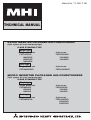
THCHNICAL MANUAL
HYPER INVERTER PACKAGED AIR-CONDITIONERS
(Split system, Air to air heat pump type)
FLOOR STANDING TYPE
Single type
Single phase use
FDF71VNXVD
100VNXVD
125VNXVD
140VNXVD
●
●
3 phase use
FDF100VSXVD
125VSXVD
140VSXVD
Twin type
Single phase use
FDF140VNXPVD
●
●
3 phase use
FDF140VSXPVD
MICRO INVERTER PACKAGED AIR-CONDITIONERS
(Split system, Air to air heat pump type)
FLOOR STANDING TYPE
Single type
Single phase use
FDF100VNVD
125VNVD
140VNVD
●
●
3 phase use
FDF100VSVD
125VSVD
140VSVD
Twin type
●
Single phase use
FDF140VNPVD
●
3 phase use
FDF140VSPVD
200VSPVD
250VSPVD
'11 • PAC-T-160
CONTENTS
1. SPECIFICATIONS ........................................................................................... 3
(1) Hyper inverter series ................................................................................... 3
(2) Micro inverter series ....................................................................................12
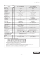
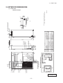
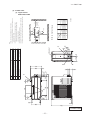
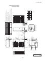
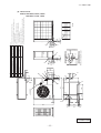
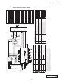
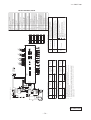
2. EXTERIOR DIMENSIONS ...............................................................................22
(1) Indoor units ..................................................................................................22
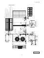
(2) Outdoor units ...............................................................................................23
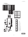
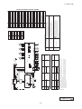
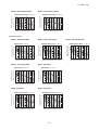
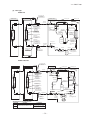
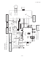
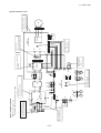
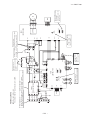
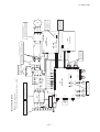
3. ELECTRICAL WIRING ....................................................................................28
(1) Indoor units ..................................................................................................28
(2) Outdoor units ...............................................................................................29
4. NOISE LEVEL .................................................................................................35
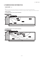
5. TEMPERATURE DISTRIBUTION ....................................................................37
6. PIPING SYSTEM .............................................................................................38
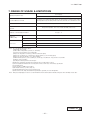
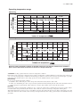
7. RANGE OF USAGE & LIMITATIONS ..............................................................41
8. SELECTION CHART .......................................................................................44
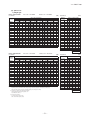
8.1 Capacity tables ...........................................................................................44
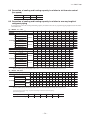
8.2 Correction of cooling and heating capacity in relation to air flow rate control (fan speed) .............54
8.3 Correction of cooling and heating capacity in relation to one way length of refrigerant piping ........54
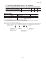
8.4 Height difference between the indoor unit and outdoor unit ..................55
9. APPLICATION DATA ......................................................................................56
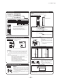
9.1 Installation of indoor unit ...........................................................................56
9.2 Electric wiring work instruction .................................................................60
9.3 Installation of outdoor unit ........................................................................64
(1) Model FDC71VNX .......................................................................................64
(2) Models FDC100㨪140VN,100㨪140VS,100㨪140VNX,100㨪140VSX .......72
(3) Models FDC200,250VS .............................................................................76
(4) Method for connecting the accessory pipe (Models FDC200,250 only) ........83
9.4 Instructions for branching pipe set (DIS-WA1,WB1,TA1,TB1) ................85
-
1-
'11 • PAC-T-160
10. OUTLINE OF OPERATION CONTROL BY MICROCOMPUTER ................. 87
(1) Remote controller ......................................................................................... 87
(2) Operation control function by the remote controller ..................................... 88
(3) Operation control function by the indoor controller ....................................... 89
(4) Operation control function by the outdoor controller ..................................... 99
(Σ) Micro inverter series................................................................................ 99
(Τ) Hyper inverter series...............................................................................110
11. MAINTENANCE DATA ..................................................................................120
11.1 Diagnosing of microcomputer circuit ...................................................120
(1) Selfdiagnosis function ...............................................................................120
(2) Troubleshooting procedure ........................................................................123
(3) Troubleshooting at the indoor unit .............................................................123
(4) Troubleshooting at the outdoor unit ...........................................................126
(5) Check of anomalous operation data with the remote controller ................139
(6) Power transistor module (including the driver PCB) inspection procedure ...........140
(7) Inverter checker for diagnosis of inverter output .......................................141
(8) Outdoor unit controller failure diagnosis circuit diagram ....................................142
11.2 Troubleshooting flow ..............................................................................148
12. OPTION PARTS ............................................................................................197
(1) Wireless kit (RCN-KIT3-E) ........................................................................197
(2) Simple wired remote conroller (RCH-E3) .................................................199
(3) Base heater kit (CW-H-E) .........................................................................205
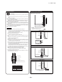
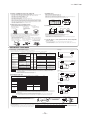
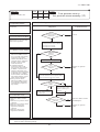
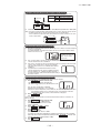
How to read the model name
Example:
FDF 140 VNX P VD
Series code
: Single type
(blank)
P : Twin type
Applicable power source...See the specification
Product capacity (14.0KW at cooling)
Model name FDF : Floor standing type
FDC : Outdoor unit
-
2-
'11 • PAC-T-160
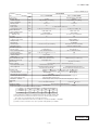
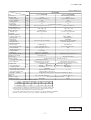
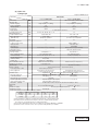
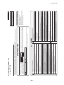
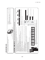
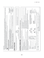
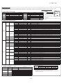
1. SPECIFICATIONS
(1) Hyper inverter series
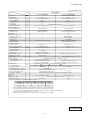
(a) Single phase use
1) Single type
Adapted to RoHS directive
Model
Item
Power source
Operation data
Nominal capacity
Power consumption
Running current
Power factor
Inrush current
Sound Pressure Level
Exterior dimensions
Height x Width x Depth
Exterior appearance
(Munsell color)
Net weight
Refrigerant equipment
Compressor type & Q'ty
Starting method
Refrigerant oil
Heat exchanger
Refrigerant control
Air handling equipment
Fan type & Q'ty
Motor <Starting method>
Air flow(Standard)
External static pressure
Outside air intake
Air filter, Q'ty
Shock & vibration absorber
Insulation (noise & heat)
Electric heater
Remote controller
Room temperature control
Safety equipment
FDF71VNXVD
Indoor unit FDF71VD
kW
kW
A
㧑
A
dB(A)
Outdoor unit FDC71VNX
220-240V~50Hz / 220V~60Hz
Cooling
Heating
7.1 [ 3.2 (Min.)~8.0 (Max.)]
8.0 [ 3.6 (Min.)~9.0 (Max.)]
2.21
2.21
9.8 / 10.3
9.9 / 10.4
98
97
5 < Max.running current 17 >
P-Hi : 42 Hi : 39 Me : 35 Lo : 33
Cooling : 51, Heating : 48
mm
1,850 × 600 × 320
750×880 (+88) × 340
kg
Ceramic White
(N8.0) near equivalent
49
Stucco White
(4.2Y7.5/1.1 ) near equivalent
60
—
—
—
Louver fine & inner grooved tubing
—
RMT5118MDE2 × 1
Direct line start
0.675 (M-MA68)
M shape fin & inner grooved tubing
Electronic expansion valve
W
CMM
Pa
W
Centrifugal fan × 1
Propeller fan × 1
157 < Direct line start >
86 < Direct line start >
P-Hi : 20 Hi : 18 Me : 16 Lo : 14
Cooling : 60, Heating : 50
—
0
Not possible
—
Plastic net × 1 (Washable)
—
Rubber sleeve (for fan motor)
Rubber sleeve (for Compressor )
Polyurethane form
—
—
20 (Crank case heater)
RC-E4 Installed / wireless : RCN-KIT3-E (option)
Thermostat by electronics
—
Overload protection for fan motor
Internal thermostat for fan motor
Abnormal discharge temperature protection.
Frost protection thermostat
Installation data
Liquid line: I/U₥9.52 (3/8") Pipe₥9.52 (3/8") × 0.8 O/U 9.52 (3/8")
mm
Refrigerant piping size
Gas line:
₥15.88 (5/8") ₥15.88 (5/8") × 1.0 ₥15.88 (5/8")
Connecting method
Flare piping
Flare piping
Refrigerant line (one way) length
Max.50m
See page 43
Vertical height difference between
Max.30m (Outdoor unit is higher)
outdoor unit and indoor unit
Max.15m (Outdoor unit is lower)
R410A 2.95kg in outdoor unit (incl. the amount for the piping of : 30m)
Refrigerant Quantity
Drain pump
—
—
Drain
Hose Connectable with VP20
Holes size ᷑20 × 3pcs
Insulation for piping
Necessary (both Liquid & Gas lines)
Standard Accessories
Mounting kit
—
Notes (1) The data are measured at the following conditions.
Outdoor air temperature
Item
Indoor air temperature
WB
DB
WB
Operation
DB
o
o
o
o
Cooling
35 C
24 C
19 C
27 C
o
o
o
20 C
7C
6C
Heating
(2) This packaged air-conditioner is manufactured and tested in conformity with the ISO.
(3) Sound pressure level indicates the value in an anechoic chamber. During operation
ẅ these value are somewhat higher due to ambient temperature.
(4) The operation data indicates when the air-conditioner is operated at 230V50Hz or 220V60Hz.
(5) If wireless remote controller is used, only 3-speed fan setting (Hi-Me-Lo) is available.
PGA000Z780
-
3-
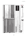
'11 • PAC-T-160
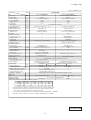
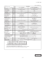
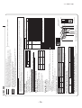
Adapted to RoHS directive
Model
Item
Power source
Operation data
Nominal capacity
Power consumption
Running current
Power factor
Inrush current
Sound Pressure Level
Exterior dimensions
Height x Width x Depth
Exterior appearance
(Munsell color)
Net weight
kW
kW
A
㧑
A
dB(A)
mm
Air handling equipment
Fan type & Q'ty
Motor <Starting method>
Air flow (Standard)
External static pressure
Outside air intake
Air filter, Q'ty
Shock & vibration absorber
Insulation (noise & heat)
Electric heater
Remote controller
Room temperature control
Safety equipment
Installation data
Refrigerant piping size
Connecting method
Refrigerant line (one way) length
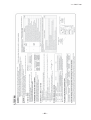
Outdoor unit FDC100VNX
Cooling
10.0 [ 4.0 (Min.)~11.2 (Max.)]
220-240V~50Hz / 220V~60Hz
Heating
11.2 [ 4.0 (Min.)~12.5 (Max.)]
2.83
12.6 / 13.1
98
3.04
13.5 / 14.1
98
5 < Max.running current 24 >
P-Hi : 54 Hi : 50 Me : 48 Lo : 44
Cooling : 48ẅHeating : 50
1,850 × 600 × 320
1,300 × 970 × 370
Ceramic White
(N8.0) near equivalent
Stucco White
(4.2Y7.5/1.1) near equivalent
kg
52
105
RMT5134MDE2 × 1
—
—
—
Refrigerant equipment
Compressor type & Q'ty
Starting method
Refrigerant oil
Heat exchanger
Refrigerant control
FDF100VNXVD
Indoor unit FDF100VD
Louver fine & inner grooved tubing
—
W
CMM
Pa
W
mm
Direct line start
0.9 M-MA68
M shape fin & inner grooved tubing
Electronic expansion valve
Centrifugal fan × 1
Propeller fan × 2
157 < Direct line start >
86 × 2 < Direct line start >
P-Hi : 29 Hi : 26 Me : 23 Lo : 19
100
—
0
Not possible
—
Plastic net × 1 (Washable)
—
Rubber sleeve (for fan motor)
Rubber sleeve (for Compressor )
Polyurethane form
—
—
20 (Crank case heater)
RC-E4 Installed ᵍ wireless : RCN-KIT3-E (option)
Thermostat by electronics
—
Overload protection for fan motor
Internal thermostat for fan motor
Abnormal discharge temperature protection.
Frost protection thermostat
Liquid line: I/U₥9.52 (3/8") Pipe₥9.52 (3/8") × 0.8 O/U₥9.52 (3/8")
Gas line:
₥15.88 (5/8") ₥15.88 (5/8") × 1.0 ₥15.88 (5/8")
Flare piping
Flare piping
Max.100m
Max.30m (Outdoor unit is higher)
Vertical height difference between
See page 43
outdoor unit and indoor unit
Max.15m (Outdoor unit is lower)
RefrigerantẅẅQuantity
R410A 4.5kg in outdoor unit (incl. the amount for the piping of : 30m)
Drain pump
—
—
Drain
Hose Connectable with VP20
Holes size ᷑20 × 3pcs
Insulation for piping
Necessary (both Liquid & Gas lines)
Edging
Standard Accessories
Mounting kit
Notes (1) The data are measured at the following conditions.
Indoor air temperature
Item
Outdoor air temperature
Operation
DB
WB
DB
WB
o
o
o
o
Cooling
27 C
35 C
24 C
19 C
o
o
o
Heating
20 C
7C
6C
(2) This packaged air-conditioner is manufactured and tested in conformity with the ISO.
(3) Sound pressure level indicates the value in an anechoic chamber. During operation
ẅ these value are somewhat higher due to ambient temperature.
(4) The operation data indicates when the air-conditioner is operated at 230V50Hz or 220V60Hz.
(5) If wireless remote controller is used, only 3-speed fan setting (Hi-Me-Lo) is available.
PGA000Z780
-
4-
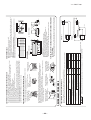
'11 • PAC-T-160
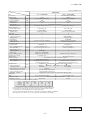
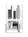
Adapted to RoHS directive
Model
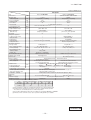
FDF125VNXVD
Indoor unit FDF125VD
Outdoor unit FDC125VNX
Cooling
12.5 [ 5.0 (Min.)~14.0 (Max.)]
220-240V~50Hz / 220V~60Hz
Heating
14.0 [ 4.0 (Min.)~17.0 (Max.)]
kW
A
㧑
A
3.89
17.3 / 18.0
98
3.88
17.2 / 18.0
98
Sound Pressure Level
dB(A)
P-Hi : 54 Hi : 50 Me : 48 Lo : 44
Cooling : 48ẅHeating : 50
Exterior dimensions
Height x Width x Depth
mm
1,850ᴾ× 600ᴾ× 320
1,300ᴾ× 970ᴾ× 370
kg
Ceramic White
(N8.0) near equivalent
52
Stucco White
(4.2Y7.5/1.1) near equivalent
105
—
—
—
Louver fine & inner grooved tubing
—
RMT5134MDE2 × 1
Direct line start
0.9 M-MA68
M shape fin & inner grooved tubing
Centrifugal fan × 1
157 < Direct line start >
P-Hiᾉ29 Hiᾉ26 Meᾉ23 Loᾉ19
Propeller fan × 2
86 x 2 < Direct line start >
100
—
Item
Power source
Operation data
Nominal capacity
Power consumption
Running current
Power factor
Inrush current
Exterior appearance
(Munsell color )
Net weight
Refrigerant equipment
Compressor type & Q'ty
Starting method
Refrigerant oil
Heat exchanger
kW
Refrigerant control
Air handling equipment
Fan type & Q'ty
Motor <Starting method>
Air flow(Standard)
External static pressure
Outside air intake
Air filter, Q'ty
Shock & vibration absorber
Insulation (noise & heat)
Electric heater
Remote controller
Room temperature control
W
CMM
Pa
W
Safety equipment
Installation data
Refrigerant piping size
Connecting method
Refrigerant line (one way) length
Vertical height difference between
outdoor unit and indoor unit
RefrigerantẅẅQuantity
Drain pump
Drain
mm
5 < Max.running current 26 >
0
Not possible
Plastic net × 1 (Washable)
Rubber sleeve (for fan motor)
Polyurethane form
—
Electronic expansion valve
—
—
Rubber sleeve (for Compressor )
—
20 (Crank case heater)
RC-E4 Installed / wireless : RCN-KIT3-Eᴾ(option)
Thermostat by electronics
—
Overload protection for fan motor
Internal thermostat for fan motor
Abnormal discharge temperature protection.
Frost protection thermostat
Liquid line: I/U₥9.52 (3/8") Pipe₥9.52(3/8") × 0.8 O/U 9.52 (3/8")
Gas line:
₥15.88 (5/8") ₥15.88(5/8") × 1.0 ₥15.88 (5/8")
Flare piping
Flare piping
Max.100m
See page 43
Max.30m (Outdoor unit is higher)
Max.15m (Outdoor unit is lower)
R410A 4.5kg in outdoor unit (incl. the amount for the piping of : 30m)
—
—
Hose Connectable with VP20
Holes size ᷑20 × 3pcs
Insulation for piping
Necessary (both Liquid & Gas lines)
Standard Accessories
Mounting kit
Notes (1) The data are measured at the following conditions.
Item
Outdoor air temperature
Indoor air temperature
Operation
WB
DB
WB
DB
o
o
o
o
Cooling
19 C
35 C
24 C
27 C
o
o
o
7C
6C
20 C
Heating
Edging
(2) This packaged air-conditioner is manufactured and tested in conformity with the ISO.
(3) Sound pressure level indicates the value in an anechoic chamber. During operation
ẅ these value are somewhat higher due to ambient temperature.
(4) The operation data indicates when the air-conditioner is operated at 230V50Hz or 220V60Hz.
(5) If wireless remote controller is used, only 3-speed fan setting (Hi-Me-Lo) is available.
PGA000Z780
-
5-
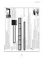
'11 • PAC-T-160
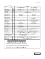
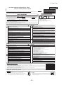
Adapted to RoHS directive
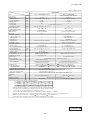
FDF140VNXVD
Model
Item
Power source
Operation data
Nominal capacity
Power consumption
Running current
Power factor
Inrush current
Sound Pressure Level
Exterior dimensions
Height x Width x Depth
Exterior appearance
(Munsell color)
Net weight
Refrigerant equipment
Compressor type & Q'ty
Starting method
Refrigerant oil
Heat exchanger
Refrigerant control
Air handling equipment
Fan type & Q'ty
Motor <Starting method>
Air flow(Standard)
External static pressure
Outside air intake
Air filter, Q'ty
Shock & vibration absorber
Insulation (noise & heat)
Electric heater
Remote controller
Room temperature control
Safety equipment
Indoor unit FDF140VD
kW
kW
A
㧑
A
dB(A)
Outdoor unit FDC140VNX
220-240V~50Hz / 220V~60Hz
Cooling
Heating
14.0 [ 5.0 (Min.)~16.0 (Max.)]
16.0 [ 4.0 (Min.)~18.0 (Max.)]
4.65
4.69
20.6 / 21.6
20.8 / 21.8
98
98
5 < Max.running current 24 >
P-Hi : 54 Hi : 50 Me : 48 Lo : 44
Cooling : 49ẅHeating : 52
mm
1,850 × 600 × 320
1,300 × 970 × 370
kg
Ceramic White
(N8.0) near equivalent
52
Stucco White
(4.2Y7.5/1.1) near equivalent
105
—
—
—
Louver fine & inner grooved tubing
—
RMT5134MDE2 × 1
Direct line start
0.9 M-MA68
M shape fin & inner grooved tubing
Electronic expansion valve
W
CMM
Pa
W
Centrifugal fan × 1
Propeller fan × 2
157 < Direct line start >
86 × 2 < Direct line start >
P-Hi : 29 Hi : 26 Me : 23 Lo : 19
100
—
0
Not possible
—
Plastic net × 1 (Washable)
—
Rubber sleeve (for fan motor)
Rubber sleeve (for Compressor )
Polyurethane form
—
—
20 (Crank case heater)
RC-E4 Installed / wireless : RCN-KIT3-E (option)
Thermostat by electronics
—
Overload protection for fan motor
Internal thermostat for fan motor
Abnormal discharge temperature protection.
Frost protection thermostat
Installation data
Liquid line: I/U₥9.52 (3/8") Pipe₥9.52 (3/8") × 0.8 O/U₥9.52 (3/8")
mm
Refrigerant piping size
Gas line:
₥15.88 (5/8") ₥15.88 (5/8") × 1.0 ₥15.88 (5/8")
Connecting method
Flare piping
Flare piping
Refrigerant line (one way) length
Max.100m
Vertical height difference between
Max.30m (Outdoor unit is higher)
See page 43
outdoor unit and indoor unit
Max.15m (Outdoor unit is lower)
R410A 4.5kg in outdoor unit (incl. the amount for the piping of : 30m)
RefrigerantẅẅQuantity
Drain pump
—
—
Drain
Holes size ᷑20 × 3pcs
Hose Connectable with VP20
Insulation for piping
Necessary (both Liquid & Gas lines)
Standard Accessories
Mounting kit
Edging
Notes (1) The data are measured at the following conditions.
Item
Outdoor air temperature
Indoor air temperature
Operation
WB
DB
WB
DB
o
o
o
o
Cooling
19 C
35 C
24 C
27 C
o
o
o
Heating
7C
6C
20 C
(2) This packaged air-conditioner is manufactured and tested in conformity with the ISO.
(3) Sound pressure level indicates the value in an anechoic chamber. During operation
ẅ these value are somewhat higher due to ambient temperature.ner is operated at 230V50Hz or 220V60Hz.
(4) The operation data indicates when the air-conditio
(5) If wireless remote controller is used, only 3-speed fan setting (Hi-Me-Lo) is available.
PGA000Z780
-
6-
'11 • PAC-T-160
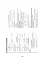
2) Twin type
Adapted to RoHS directive
FDF140VNXPVD
Model
Item
Power source
Operation data
Nominal capacity
Power consumption
Running current
Power factor
Inrush current
Sound Pressure Level
Exterior dimensions
Height x Width x Depth
Exterior appearance
(Munsell color)
Net weight
Refrigerant equipment
Compressor type & Q'ty
Starting method
Refrigerant oil
Heat exchanger
Refrigerant control
Air handling equipment
Fan type & Q'ty
Motor <Starting method>
Air flow (Standard)
External static pressure
Outside air intake
Air filter, Q'ty
Shock & vibration absorber
Insulation (noise & heat)
Electric heater
kW
kW
A
Outdoor unit FDC140VNX
Cooling
14.0 [ 5.0 (Min.) ~16.0 (Max.)]
220-240V~50Hz / 220V~60Hz
Heating
16.0 [ 4.0 (Min.) ~18.0 (Max.)]
4.83
21.4 / 22.4
4.97
22.0 / 23.1
㧑
A
dB(A)
P-Hi : 42 Hi : 39 Me : 35 Lo : 33
Cooling : 49ẅHeating : 52
mm
1,850 × 600 × 320
1,300 × 970 × 370
Ceramic White
(N8.0) near equivalent
Stucco White
(4.2Y7.5/1.1) near equivalent
kg
49
105
RMT5134MDE2 × 1
Direct line start
—
—
—
Louver fine & inner grooved tubing
—
0.9 M-MA68
M shape fin & inner grooved tubing
Electronic expansion valve
Centrifugal fan × 1
157 < Direct line start >
Propeller fan × 2
86 x 2 < Direct line start >
P-Hi : 18 Hi : 16 Me : 14 Lo : 12
0
Not possible
Plastic net × 1 (Washable)
Rubber sleeve (for fan motor)
100
—
—
—
Rubber sleeve (for Compressor )
Polyurethane form
—
—
20 (Crank case heater)
W
CMM
Pa
W
Remote controller
Room temperature control
98
98
5 < Max.running current 26 >
RC-E4 Installedᴾᵍᴾwireless : RCN-KIT3-E (option)
—
Thermostat by electronics
Safety equipment
Installation data
Refrigerant piping size
Connecting method
Indoor unit FDF71VD (2 units)
Overload protection for fan motor
Frost protection thermostat
mm
Internal thermostat for fan motor
Abnormal discharge temperature protection.
Liquid line: I/U₥9.52 (3/8") ℳ₥9.52 (3/8") × 0.8 Ⅎ₥9.52 (3/8") × 0.8
O/U₥9.52 (3/8")
Gas line: I/U₥15.88 (5/8") ℳ₥15.88 (5/8") × 1.0 Ⅎ₥15.88 (5/8") × 1.0 O/U₥15.88 (5/8")
Flare piping
Refrigerant line (one way) length
Flare piping
Max.100m
See page 43
Max.30m (Outdoor unit is higher)
Max.15m (Outdoor unit is lower)
R410A 4.5kg (Pre-charged up to the piping length of 30m) Outdoor unit
—
—
Holes size ᷑20 × 3pcs
Hose Connectable with VP20
Drain
Insulation for piping
Necessary (both Liquid & Gas lines)
Standard Accessories
Mounting kit
Edging
Notes (1) The data are measured at the following conditions.
Item
Indoor air temperature
Outdoor air temperature
Operation
DB
WB
DB
WB
o
o
o
o
Cooling
19 C
27 C
35 C
24 C
o
o
o
Heating
7C
6C
20 C
Vertical height difference between
outdoor unit and indoor unit
RefrigerantẅẅQuantity
Drain pump
(2) This packaged air-conditioner is manufactured and tested in conformity with the ISO.
(3) Sound pressure level indicates the value in an anechoic chamber. During operation
ẅ these value are somewhat higher due to ambient temperature.
(4) The operation data indicates when the air-conditioner is operated at 230V50Hz or 220V60Hz.
(5) Indoor unit specifications for one unit. Capacity and operation data is two indoor units are combined and run together.
(6) Branching pipe set "DIS-WA1" × 1 (option). Ṟ : Pipe of O/U~Branch, ṟ : Pipe of Branch~I/U
(7) If wireless remote controller is used, only 3-speed fan setting (Hi-Me-Lo) is available.
PGA000Z780
-
7-
'11 • PAC-T-160
(b) 3 phase use
1) Single type
Adapted to RoHS directive
FDF100VSXVD
Model
Item
Operation data
Nominal capacity
Power consumption
Running current
Power factor
Inrush current
Sound Pressure Level
Exterior dimensions
Height x Width x Depth
Exterior appearance
(Munsell color)
Net weight
Refrigerant equipment
Compressor type & Q'ty
Starting method
Refrigerant oil
Heat exchanger
Refrigerant control
Air handling equipment
Fan type & Q'ty
Motor <Starting method>
Air flow(Standard)
External static pressure
Outside air intake
Air filter, Q'ty
Shock & vibration absorber
Insulation (noise & heat)
Electric heater
Remote controller
Room temperature control
Safety equipment
kW
kW
A
㧑
A
dB(A)
mm
kg
W
CMM
Pa
W
Indoor unit FDF100VD
Outdoor unit FDC100VSX
Cooling
10.0 [ 4.0 (Min.)~11.2 (Max.)]
380-415V 3N~50Hz / 380V 3N~60Hz
Heating
11.2 [ 4.0 (Min.)~16.0 (Max.)]
2.83
4.2 / 4.4
3.04
4.5 / 4.7
97 / 98
98
5 < Max.running current 15 >
Cooling : 48ẅHeating : 50
P-Hi : 54 Hi : 50 Me : 48 Lo : 44
1,850 × 600 × 320
1,300 × 970 × 370
Ceramic White
(N8.0) near equivalent
Stucco White
(4.2Y7.5/1.1) near equivalent
52
105
—
—
—
Louver fine & inner grooved tubing
RMT5134MDE3 × 1
Direct line start
0.9 M-MA68
M shape fin & inner grooved tubing
—
Electronic expansion valve
Centrifugal fan × 1
Propeller fan × 2
157 < Direct line start >
P-Hi : 29 Hi : 26 Me : 23 Lo : 19
86 × 2 < Direct line start >
100
—
0
Not possible
Plastic net × 1 (Washable)
Rubber sleeve (for fan motor)
Polyurethane form
—
—
Rubber sleeve (for Compressor )
—
—
20 (Crank case heater)
RC-E4 Installed / wireless : RCN-KIT3-E (option)
Thermostat by electronics
—
Overload protection for fan motor
Internal thermostat for fan motor
Abnormal discharge temperature protection.
Frost protection thermostat
Liquid line: I/U₥9.52 (3/8") Pipe₥9.52 (3/8") × 0.8 O/U 9.52 (3/8")
Gas line:
₥15.88 (5/8") ₥15.88 (5/8") × 1.0 ₥15.88 (5/8")
Flare piping
Flare piping
Installation data
mm
Refrigerant piping size
Connecting method
Refrigerant line (one way) length
Max.100m
Vertical height difference between
See page 43
Max.30m (Outdoor unit is higher)
Max.15m (Outdoor unit is lower)
outdoor unit and indoor unit
RefrigerantẅẅQuantity
R410A 4.5kg in outdoor unit (incl. the amount for the piping of : 30m)
Drain pump
—
—
Hose Connectable with VP20
Holes size ᷑20 × 3pcs
Drain
Insulation for piping
Necessary (both Liquid & Gas lines)
Standard Accessories
Mounting kit
Edging
Notes (1) The data are measured at the following conditions.
Item
Indoor air temperature
Outdoor air temperature
Operation
DB
WB
DB
WB
o
o
o
o
Cooling
27 C
19 C
35 C
24 C
o
o
o
Heating
7C
6C
20 C
(2) This packaged air-conditioner is manufactured and tested in conformity with the ISO.
(3) Sound pressure level indicates the value in an anechoic chamber. During operation
ẅ these value are somewhat higher due to ambient temperature.
(4) The operation data indicates when the air-conditioner is operated at 400V50Hz or 380V60Hz.
(5) If wireless remote controller is used, only 3-speed fan setting (Hi-Me-Lo) is available.
PGA000Z780
-
8-
'11 • PAC-T-160
Adapted to RoHS directive
FDF125VSXVD
Model
Item
Power source
Operation data
Nominal capacity
Power consumption
Running current
Power factor
Inrush current
Sound Pressure Level
Exterior dimensions
Height x Width x Depth
Exterior appearance
(Munsell color)
Net weight
Refrigerant equipment
Compressor type & Q'ty
Starting method
Refrigerant oil
Heat exchanger
Refrigerant control
Air handling equipment
Fan type & Q'ty
Motor <Starting method>
Air flow(Standard)
External static pressure
Outside air intake
Air filter, Q'ty
Shock & vibration absorber
Insulation (noise & heat)
Electric heater
Remote controller
Room temperature control
Safety equipment
kW
kW
A
㧑
A
dB(A)
Indoor unit FDF125VD
Outdoor unit FDC125VSX
Cooling
12.5 [ 5.0 (Min.)~14.0 (Max.)]
380-415V 3N~50Hz / 380V 3N~60Hz
Heating
14.0 [ 4.0 (Min.)~18.0 (Max.)]
3.89
5.7 / 6.0
99
3.88
5.7 / 6.0
98
5 < Max.running current 15 >
P-Hi : 54 Hi : 50 Me : 48 Lo : 44
Cooling : 48ẅHeating : 50
mm
1,850 × 600 × 320
1,300 × 970 × 370
kg
Ceramic White
(N8.0) near equivalent
52
Stucco White
(4.2Y7.5/1.1) near equivalent
105
—
—
—
Louver fine & inner grooved tubing
—
RMT5134MDE3 × 1
Direct line start
0.9 M-MA68
M shape fin & inner grooved tubing
Electronic expansion valve
W
CMM
Pa
W
Centrifugal fan × 1
Propeller fan × 2
157 < Direct line start >
86 × 2 < Direct line start >
P-Hi : 29 Hi : 26 Me : 23 Lo : 19
100
—
0
Not possible
—
Plastic net × 1 (Washable)
—
Rubber sleeve (for fan motor)
Rubber sleeve (for Compressor )
Polyurethane form
—
—
20 (Crank case heater)
RC-E4 Installed / wireless : RCN-KIT3-Eẅ(option)
Thermostat by electronics
—
Overload protection for fan motor
Internal thermostat for fan motor
Abnormal discharge temperature protection.
Frost protection thermostat
Liquid line: I/U₥9.52 (3/8") Pipe₥9.52 (3/8") × 0.8 O/U 9.52 (3/8")
Installation data
mm
Gas line:
₥15.88 (5/8") ₥15.88 (5/8") × 1.0 ₥15.88 (5/8")
Refrigerant piping size
Connecting method
Flare piping
Flare piping
Max.100m
Refrigerant line (one way) length
See page 43
Max.30m (Outdoor unit is higher)
Vertical height difference between
Max.15m (Outdoor unit is lower)
outdoor unit and indoor unit
RefrigerantẅẅQuantity
R410A 4.5kg in outdoor unit (incl. the amount for the piping of : 30m)
Drain pump
—
—
Hose Connectable with VP20
Holes size ᷑20 × 3pcs
Drain
Insulation for piping
Necessary (both Liquid & Gas lines)
Standard Accessories
Mounting kit
Edging
Notes (1) The data are measured at the following conditions.
Item
Outdoor air temperature
Indoor air temperature
Operation
WB
DB
WB
DB
o
o
o
o
Cooling
19 C
35 C
24 C
27 C
o
o
o
Heating
7C
6C
20 C
(2) This packaged air-conditioner is manufactured and tested in conformity with the ISO.
(3) Sound pressure level indicates the value in an anechoic chamber. During operation
ẅ these value are somewhat higher due to ambient temperature.
(4) The operation data indicates when the air-conditioner is operated at 400V50Hz or 380V60Hz.
(5) If wireless remote controller is used, only 3-speed fan setting (Hi-Me-Lo) is available.
PGA000Z780
-
9-
'11 • PAC-T-160
Adapted to RoHS directive
Model
Item
Power source
Operation data
Nominal capacity
Power consumption
Running current
Power factor
Inrush current
Sound Pressure Level
Exterior dimensions
Height x Width x Depth
Exterior appearance
(Munsell color)
Net weight
Refrigerant equipment
Compressor type & Q'ty
Starting method
Refrigerant oil
Heat exchanger
Refrigerant control
Air handling equipment
Fan type & Q'ty
Motor <Starting method>
Air flow(Standard)
External static pressure
Outside air intake
Air filter, Q'ty
Shock & vibration absorber
Insulation (noise & heat)
Electric heater
Remote controller
Room temperature control
FDF140VSXVD
Indoor unit FDF140VD
Outdoor unit FDC140VSX
380-415V 3N~50Hz / 380V 3N~60Hz
kW
Cooling
14.0 [ 5.0 (Min.)~16.0 (Max.)]
Heating
16.0 [ 4.0 (Min.)~20.0 (Max.)]
4.65
6.8 / 7.2
99/98
4.69
6.9 / 7.3
98
kW
A
㧑
A
dB(A)
P-Hi : 54 Hi : 50 Me : 48 Lo : 44
Cooling : 49ẅHeating : 52
mm
1,850 × 600 × 320
1,300 × 970 × 370
kg
Ceramic White
(N8.0) near equivalent
52
Stucco White
(4.2Y7.5/1.1) near equivalent
105
—
—
—
Louver fine & inner grooved tubing
—
RMT5134MDE3 × 1
Direct line start
0.9 M-MA68
M shape fin & inner grooved tubing
Electronic expansion valve
W
CMM
Pa
Centrifugal fan × 1
157 < Direct line start >
P-Hi : 29 Hi : 26 Me : 23 Lo : 19
0
Not possible
Propeller fan × 2
86 × 2 < Direct line start >
100
—
W
5 < Max.running current 15 >
—
Plastic net × 1 (Washable)
—
Rubber sleeve (for fan motor)
Rubber sleeve (for Compressor )
Polyurethane form
—
—
20 (Crank case heater)
RC-E4 Installedẅ/ẅwireless : RCN-KIT3-Eẅ(option)
Thermostat by electronics
—
Safety equipment
Overload protection for fan motor
Internal thermostat for fan motor
Abnormal discharge temperature protection.
Frost protection thermostat
Liquid line: I/U₥9.52 (3/8") Pipe₥9.52 (3/8") × 0.8 O/U 9.52 (3/8")
Installation data
mm
Gas line:
₥15.88 (5/8") ₥15.88 (5/8") × 1.0 ₥15.88 (5/8")
Refrigerant piping size
Connecting method
Flare piping
Flare piping
Max.100m
Refrigerant line (one way) length
See page 43
Max.30m (Outdoor unit is higher)
Vertical height difference between
Max.15m (Outdoor unit is lower)
outdoor unit and indoor unit
RefrigerantẅẅQuantity
R410A 4.5kg in outdoor unit (incl. the amount for the piping of : 30m)
Drain pump
—
—
Holes size ᷑20 × 3pcs
Hose Connectable with VP20
Drain
Insulation for piping
Necessary (both Liquid & Gas lines)
Mounting kit
Edging
Standard Accessories
Notes (1) The data are measured at the following conditions.
Item
Outdoor air temperature
Indoor air temperature
Operation
WB
DB
WB
DB
o
o
o
o
Cooling
19 C
35 C
24 C
27 C
o
o
o
Heating
7C
6C
20 C
(2) This packaged air-conditioner is manufactured and tested in conformity with the ISO.
(3) Sound pressure level indicates the value in an anechoic chamber. During operation
ẅ these value are somewhat higher due to ambient temperature.
(4) The operation data indicates when the air-conditioner is operated at 400V50Hz or 380V60Hz.
(5) If wireless remote controller is used, only 3-speed fan setting (Hi-Me-Lo) is available.
PGA000Z780
-
10 -
'11 • PAC-T-160
2) Twin type
Adapted to RoHS directive
Model
Item
Power source
Operation data
Nominal capacity
Power consumption
Running current
Power factor
Inrush current
Sound Pressure Level
Exterior dimensions
Height x Width x Depth
Exterior appearance
(Munsell color)
Net weight
Refrigerant equipment
Compressor type & Q'ty
Starting method
Refrigerant oil
Heat exchanger
Refrigerant control
Air handling equipment
Fan type & Q'ty
Motor <Starting method>
Air flow(Standard)
External static pressure
Outside air intake
Air filter, Q'ty
Shock & vibration absorber
Insulation (noise & heat)
Electric heater
Remote controller
Room temperature control
Safety equipment
FDF140VSXPVD
Indoor unit FDF71VD (2 units)
kW
kW
A
㧑
A
dB(A)
Outdoor unit FDC140VSX
380-415V 3N~50Hz / 380V 3N~60Hz
Heating
Cooling
14.0 [ 5.0 (Min.)~16.0 (Max.)]
16.0 [ 4.0 (Min.)~20.0 (Max.)]
4.83
4.97
7.1 / 7.5
7.3 / 7.7
98
98
5 < Max.running current 15 >
Cooling : 49ẅHeating : 52
P-Hi : 42 Hi : 39 Me : 35 Lo : 33
mm
1,850 × 600 × 320
1,300 × 970 × 370
kg
Ceramic White
(N8.0) near equivalent
49
Stucco White
(4.2Y7.5/1.1) near equivalent
105
—
RMT5134MDE3 × 1
—
—
Louver fine & inner grooved tubing
—
Direct line start
0.9 M-MA68
M shape fin & inner grooved tubing
Electronic expansion valve
Centrifugal fan × 1
157 < Direct line start >
P-Hi : 18 Hi : 16 Me : 14 Lo : 12
0
Not possible
Propeller fan × 2
86 x 2 < Direct line start >
100
—
W
CMM
Pa
W
—
Plastic net × 1 (Washable)
—
Rubber sleeve (for fan motor)
Rubber sleeve (for Compressor )
Polyurethane form
—
—
20 (Crank case heater)
RC-E4 Installed / wireless : RCN-KIT3-E (option)
Thermostat by electronics
—
Overload protection for fan motor
Internal thermostat for fan motor
Abnormal discharge temperature protection.
Frost protection thermostat
Liquid line: I/U₥9.52 (3/8") ℳ₥9.52 (3/8") × 0.8 Ⅎ₥9.52 (3/8") × 0.8 O/U₥9.52 (3/8")
Installation data
mm
Gas line: I/U₥15.88 (5/8") ℳ₥15.88 (5/8") × 1.0 Ⅎ₥15.88 (5/8") × 1.0 O/U₥15.88 (5/8")
Refrigerant piping size
Connecting method
Flare piping
Flare piping
Max.100m
Refrigerant line (one way) length
See page 43
Max.30m (Outdoor unit is higher)
Vertical height difference between
Max.15m (Outdoor unit is lower)
outdoor unit and indoor unit
RefrigerantẅẅQuantity
R410A 4.5kg (Pre-charged up to the piping length of 30m) Outdoor unit
Drain pump
—
—
Holes size ᷑20 × 3pcs
Hose Connectable with VP20
Drain
Insulation for piping
Necessary (both Liquid & Gas lines)
Standard Accessories
Mounting kit
Edging
Notes (1) The data are measured at the following conditions.
Item
Indoor air temperature
Outdoor air temperature
Operation
DB
WB
DB
WB
o
o
o
o
Cooling
19 C
27 C
35 C
24 C
o
o
o
Heating
7C
6C
20 C
(2) This packaged air-conditioner is manufactured and tested in conformity with the ISO.
(3) Sound pressure level indicates the value in an anechoic chamber. During operation
ẅ these value are somewhat higher due to ambient temperature.
(4) The operation data indicates when the air-conditioner is operated at 400V50Hz or 380V60Hz.
(5) Indoor unit specifications for one unit. Capacity and operation data is two indoor units are combined and run together.
(6) Branching pipe set "DIS-WA1" × 1 (option). Ṟ : Pipe of O/U~Branch, ṟ : Pipe of Branch~I/U
(7) If wireless remote controller is used, only 3-speed fan setting (Hi-Me-Lo) is available.
PGA000Z780
-
11 -
'11 • PAC-T-160
(2) Micro inverter series
(a) Single plase use
1) Single type
Adapted to RoHS directive
Model
Item
Power source
Operation data
Nominal capacity
Power consumption
Running current
Power factor
Inrush current
Sound Pressure Level
Exterior dimensions
Height x Width x Depth
Exterior appearance
(Munsell color)
Net weight
Outdoor unit FDC100VN
Cooling
10.0 [ 4.0 (Min.)~11.2 (Max.)]
3.12
13.8 / 14.5
220-240V~50Hz / 220V~60Hz
Heating
11.2 [ 4.0 (Min.)~12.5 (Max.)]
3.10
13.8 / 14.4
㧑
A
98
98
dB(A)
P-Hi : 54 Hi : 50 Me : 48 Lo : 44
49
mm
1,850 × 600 × 320
845 × 970 × 370
Ceramic White
(N8.0) near equivalent
Stucco White
(4.2Y7.5/1.1) near equivalent
kg
52
81
—
RMT5126MDE2 × 1
—
—
Louver fine & inner grooved tubing
Direct line start
0.9 M-MA68
M shape fin & inner grooved tubing
Electronic expansion valve
kW
kW
A
Refrigerant equipment
Compressor type & Q'ty
Starting method
Refrigerant oil
Heat exchanger
Refrigerant control
Air handling equipment
Fan type & Q'ty
Motor <Starting method>
Air flow (Standard)
External static pressure
Outside air intake
Air filter, Q'ty
Shock & vibration absorber
Insulation (noise & heat)
Electric heater
W
CMM
Pa
W
Centrifugal fan × 1
157 < Direct line start >
P-Hi : 29 Hi : 26 Me : 23 Lo : 19
0
Not possible
Plastic net × 1 (Washable)
Rubber sleeve (for fan motor)
Polyurethane form
—
Propeller fan × 1
86 < Direct line start >
Cooling : 75, Heating : 73
—
—
—
Rubber sleeve (for Compressor )
—
20 (Crank case heater)
RC-E4 Installed / wireless : RCN-KIT3-E (option)
Thermostat by electronics
—
Overload protection for fan motor
Internal thermostat for fan motor
Abnormal discharge temperature protection.
Frost protection thermostat
Safety equipment
Connecting method
Refrigerant line (one way) length
Vertical height difference between
outdoor unit and indoor unit
5 < Max.running current 24 >
—
Remote controller
Room temperature control
Installation data
Refrigerant piping size
FDF100VNVD
Indoor unit FDF100VD
mm
Liquid line: I/U₥9.52 (3/8") Pipe₥9.52 (3/8") × 0.8 O/U 9.52 (3/8")
Gas line:
₥15.88 (5/8") ₥15.88 (5/8") × 1.0 ₥15.88 (5/8")
Flare piping
Flare piping
Max.50m
See page 43
Max.30m (Outdoor unit is higher)
Max.15m (Outdoor unit is lower)
R410A 3.8kg in outdoor unit (incl. the amount for the piping of : 30m)
RefrigerantẅẅQuantity
Drain pump
—
—
Holes size ᷑20 × 3pcs
Hose Connectable with VP20
Drain
Insulation for piping
Necessary (both Liquid & Gas lines)
Standard Accessories
Mounting kit
Edging
Notes (1) The data are measured at the following conditions.
Item
Outdoor air temperature
Indoor air temperature
Operation
WB
DB
WB
DB
o
o
o
o
Cooling
19 C
35 C
24 C
27 C
o
o
o
Heating
7C
6C
20 C
(2) This packaged air-conditioner is manufactured and tested in conformity with the ISO.
(3) Sound pressure level indicates the value in an anechoic chamber. During operation
ẅ these value are somewhat higher due to ambient temperature.
(4) The operation data indicates when the air-conditioner is operated at 230V50Hz or 220V60Hz.
(5) If wireless remote controller is used, only 3-speed fan setting (Hi-Me-Lo) is available.
PGA000Z780
-
12 -
'11 • PAC-T-160
Adapted to RoHS directive
Model
Item
Power source
Operation data
Nominal capacity
Power consumption
Running current
Power factor
Inrush current
Sound Pressure Level
Exterior dimensions
Height x Width x Depth
Exterior appearance
(Munsell color)
Net weight
Indoor unit FDF125VD
kW
kW
A
㧑
A
P-Hi : 54 Hi : 50 Me : 48 Lo : 44
Cooling : 50ẅHeating : 51
mm
1,850 × 600 × 320
845 × 970 × 370
kg
Ceramic White
(N8.0) near equivalent
52
Stucco White
(4.2Y7.5/1.1) near equivalent
81
—
RMT5126MDE2 × 1
—
Direct line start
—
Louver fine & inner grooved tubing
—
0.9 M-MA68
M shape fin & inner grooved tubing
Electronic expansion valve
Starting method
Air handling equipment
Fan type & Q'ty
Motor <Starting method>
Air flow(Standard)
External static pressure
Outside air intake
Air filter, Q'ty
Shock & vibration absorber
Insulation (noise & heat)
Electric heater
Remote controller
Room temperature control
W
CMM
Pa
W
Safety equipment
Installation data
Refrigerant piping size
Connecting method
Refrigerant line (one way) length
Outdoor unit FDC125VN
220-240V~50Hz / 220V~60Hz
Cooling
Heating
12.5 [ 5.0 (Min.)~14.0 (Max.)]
14.0 [ 4.0 (Min.)~16.0 (Max.)]
4.40
4.36
19.5 / 20.4
19.3 / 20.2
98
98
5 < Max.running current 24 >
dB(A)
Refrigerant equipment
Compressor type & Q'ty
Refrigerant oil
Heat exchanger
Refrigerant control
FDF125VNVD
mm
Centrifugal fan × 1
Propeller fan × 1
157 < Direct line start >
P-Hi : 29 Hi : 26 Me : 23 Lo : 19
86 < Direct line start >
Cooling : 75, Heating : 73
—
0
Not possible
—
Plastic net × 1 (Washable)
—
Rubber sleeve (for fan motor)
Rubber sleeve (for Compressor )
Polyurethane form
—
20 (Crank case heater)
—
RC-E4 Installed / wireless : RCN-KIT3-E (option)
Thermostat by electronics
—
Overload protection for fan motor
Internal thermostat for fan motor
Abnormal discharge temperature protection.
Frost protection thermostat
Liquid line: I/U₥9.52 (3/8") Pipe₥9.52 (3/8") × 0.8 O/U 9.52 (3/8")
Gas line:
₥15.88 (5/8") ₥15.88 (5/8") × 1.0 ₥15.88 (5/8")
Flare piping
Flare piping
Max.50m
See page 43
Max.30m (Outdoor unit is higher)
Vertical height difference between
Max.15m (Outdoor unit is lower)
outdoor unit and indoor unit
R410A 3.8kg in outdoor unit (incl. the amount for the piping of : 30m)
RefrigerantẅẅQuantity
Drain pump
—
—
Hose Connectable with VP20
Holes size ᷑20 × 3pcs
Drain
Insulation for piping
Necessary (both Liquid & Gas lines)
Edging
Standard Accessories
Mounting kit
Notes (1) The data are measured at the following conditions.
Item
Indoor air temperature
Outdoor air temperature
Operation
WB
DB
WB
DB
o
o
o
o
Cooling
19 C
35 C
24 C
27 C
o
o
o
Heating
7C
6C
20 C
(2) This packaged air-conditioner is manufactured and tested in conformity with the ISO.
(3) Sound pressure level indicates the value in an anechoic chamber. During operation
ẅ these value are somewhat higher due to ambient temperature.
(4) The operation data indicates when the air-conditioner is operated at 230V50Hz or 220V60Hz.
(5) If wireless remote controller is used, only 3-speed fan setting (Hi-Me-Lo) is available.
PGA000Z780
-
13 -
'11 • PAC-T-160
Adapted to RoHS directive
Model
Item
Power source
Operation data
Nominal capacity
Power consumption
Running current
Power factor
Inrush current
Sound Pressure Level
Exterior dimensions
Height x Width x Depth
Exterior appearance
(Munsell color)
Net weight
Refrigerant equipment
Compressor type & Q'ty
Starting method
Refrigerant oil
Heat exchanger
Refrigerant control
Air handling equipment
Fan type & Q'ty
Motor <Starting method>
Air flow(Standard)
External static pressure
kW
kW
A
㧑
Vertical height difference between
outdoor unit and indoor unit
RefrigerantẅẅQuantity
Cooling
14.0 [ 5.0 (Min.)~14.5 (Max.)]
5.15
22.8 / 23.9
98
23.6 / 24.6
98
5 < Max.running current 24 >
P-Hi : 54 Hi : 50 Me : 48 Lo : 44
51
mm
1,850 × 600 × 320
845 × 970 × 370
Ceramic White
(N8.0) near equivalent
Stucco White
(4.2Y7.5/1.1) near equivalent
kg
52
81
—
—
—
Louver fine & inner grooved tubing
—
RMT5126MDE2 × 1
Direct line start
0.9 M-MA68
M shape fin & inner grooved tubing
Electronic expansion valve
Centrifugal fan × 1
157 < Direct line start >
P-Hi : 29 Hi : 26 Me : 23 Lo : 19
0
Propeller fan × 1
86 < Direct line start >
Cooling : 75, Heating : 73
—
Not possible
Plastic net × 1 (Washable)
Rubber sleeve (for fan motor)
Polyurethane form
—
—
W
CMM
Pa
W
Safety equipment
Installation data
Refrigerant piping size
Connecting method
Refrigerant line (one way) length
Outdoor unit FDC140VN
220-240V~50Hz / 220V~60Hz
Heating
16.0 [ 4.0 (Min.)~16.5 (Max.)]
5.31
A
dB(A)
Outside air intake
Air filter, Q'ty
Shock & vibration absorber
Insulation (noise & heat)
Electric heater
Remote controller
Room temperature control
FDF140VNVD
Indoor unit FDF140VD
mm
Rubber sleeve (for Compressor )
—
—
20 (Crank case heater)
RC-E4 Installed / wireless : RCN-KIT3-E (option)
—
Thermostat by electronics
Overload protection for fan motor
Internal thermostat for fan motor
Abnormal discharge temperature protection.
Frost protection thermostat
Liquid line: I/U₥9.52 (3/8") Pipe₥9.52 (3/8") × 0.8 O/U 9.52 (3/8")
Gas line:
₥15.88 (5/8") ₥15.88 (5/8") × 1.0 ₥15.88 (5/8")
Flare piping
Flare piping
Max.50m
See page 43
Max.30m (Outdoor unit is higher)
Max.15m (Outdoor unit is lower)
R410A 3.8kg in outdoor unit (incl. the amount for the piping of : 30m)
Drain pump
—
—
Holes size ᷑20 × 3pcs
Hose Connectable with VP20
Drain
Insulation for piping
Necessary (both Liquid & Gas lines)
Standard Accessories
Mounting kit
Edging
Notes (1) The data are measured at the following conditions.
Outdoor air temperature
Item
Indoor air temperature
Operation
WB
DB
WB
DB
o
o
o
o
Cooling
19 C
35 C
24 C
27 C
o
o
o
Heating
7C
6C
20 C
(2) This packaged air-conditioner is manufactured and tested in conformity with the ISO.
(3) Sound pressure level indicates the value in an anechoic chamber. During operation
ẅ these value are somewhat higher due to ambient temperature.
(4) The operation data indicates when the air-conditioner is operated at 230V50Hz or 220V60Hz.
(5) If wireless remote controller is used, only 3-speed fan setting (Hi-Me-Lo) is available.
PGA000Z780
-
14 -
'11 • PAC-T-160
2) Twin type
Adapted to RoHS directive
Model
Item
Power source
Operation data
Nominal capacity
Power consumption
Running current
Power factor
Inrush current
Sound Pressure Level
Exterior dimensions
Height x Width x Depth
Exterior appearance
(Munsell color)
Net weight
Refrigerant equipment
Compressor type & Q'ty
Starting method
Refrigerant oil
Heat exchanger
Refrigerant control
Air handling equipment
Fan type & Q'ty
Motor <Starting method>
Air flow(Standard)
External static pressure
Outside air intake
Air filter, Q'ty
Shock & vibration absorber
Insulation (noise & heat)
Electric heater
Remote controller
Room temperature control
Safety equipment
kW
kW
A
㧑
FDF140VNPVD
Indoor unit FDF71VD (2 units)
Outdoor unit FDC140VN
Cooling
14.0 [ 5.0 (Min.)~14.5 (Max.)]
220-240V~50Hz / 220V~60Hz
Heating
16.0 [ 4.0 (Min.)~16.5 (Max.)]
5.16
22.9 / 23.9
98
5.01
22.2 / 23.2
98
5 < Max.running current 24 >
A
dB(A)
P-Hi : 42 Hi : 39 Me : 35 Lo : 33
51
mm
1,850 × 600 × 320
845 × 970 × 370
Ceramic White
(N8.0) near equivalent
Stucco White
(4.2Y7.5/1.1) near equivalent
49
81
—
—
—
Louver fine & inner grooved tubing
RMT5126MDE2 × 1
Direct line start
0.9 M-MA68
M shape fin & inner grooved tubing
—
Electronic expansion valve
Centrifugal fan × 1
157 < Direct line start >
P-Hi : 18 Hi : 16 Me : 14 Lo : 12
Propeller fan × 1
86 < Direct line start >
Cooling : 75, Heating : 73
—
kg
W
CMM
Pa
W
0
Not possible
Plastic net × 1 (Washable)
Rubber sleeve (for fan motor)
Polyurethane form
—
—
—
Rubber sleeve (for Compressor )
—
20 (Crank case heater)
RC-E4 Installed / wireless : RCN-KIT3-E (option)
Thermostat by electronics
—
Overload protection for fan motor
Internal thermostat for fan motor
Abnormal discharge temperature protection.
Frost protection thermostat
Liquid line: I/U₥9.52 (3/8") ℳ₥9.52 (3/8") × 0.8 Ⅎ₥9.52 (3/8") × 0.8 O/U₥9.52 (3/8")
Installation data
mm
Gas line: I/U₥15.88 (5/8") ℳ₥15.88 (5/8") × 1.0 Ⅎ₥15.88 (5/8") × 1.0 O/U₥15.88 (5/8")
Refrigerant piping size
Connecting method
Flare piping
Flare piping
Max.50m
Refrigerant line (one way) length
See page 43
Max.30m (Outdoor unit is higher)
Vertical height difference between
Max.15m (Outdoor unit is lower)
outdoor unit and indoor unit
RefrigerantẅẅQuantity
R410A 3.8kg (Pre-charged up to the piping length of 30m) Outdoor unit
Drain pump
—
—
Hose Connectable with VP20
Holes size ᷑20 × 3pcs
Drain
Insulation for piping
Necessary (both Liquid & Gas lines)
Standard Accessories
Mounting kit
Edging
Notes (1) The data are measured at the following conditions.
Indoor air temperature
Outdoor air temperature
Item
Operation
DB
WB
DB
WB
o
o
o
o
Cooling
27 C
19 C
35 C
24 C
o
o
o
7C
6C
20 C
Heating
(2) This packaged air-conditioner is manufactured and tested in conformity with the ISO.
(3) Sound pressure level indicates the value in an anechoic chamber. During operation
ẅ these value are somewhat higher due to ambient temperature.
(4) The operation data indicates when the air-conditioner is operated at 230V50Hz or 220V60Hz.
(5) Indoor unit specifications for one unit. Capacity and operation data is two indoor units are combined and run together.
(6) Branching pipe set "DIS-WA1" × 1 (option). Ṟ : Pipe of O/U~Branch, ṟ : Pipe of Branch~I/U
(7) If wireless remote controller is used, only 3-speed fan setting (Hi-Me-Lo) is available.
PGA000Z780
-
15 -
'11 • PAC-T-160
(b) 3 plase use
1) Single type
Adapted to RoHS directive
Model
Item
Power source
Operation data
Nominal capacity
Power consumption
Running current
Power factor
Inrush current
Sound Pressure Level
Exterior dimensions
Height x Width x Depth
Exterior appearance
(Munsell color)
Net weight
Refrigerant equipment
Compressor type & Q'ty
Starting method
Refrigerant oil
Heat exchanger
Refrigerant control
Air handling equipment
Fan type & Q'ty
Motor <Starting method>
Air flow(Standard)
External static pressure
Outside air intake
Air filter, Q'ty
Shock & vibration absorber
Insulation (noise & heat)
Electric heater
Remote controller
Room temperature control
Safety equipment
FDF100VSVD
Indoor unit FDF100VD
Outdoor unit FDC100VS
380-415V 3N~50Hz / 380V 3N~60Hz
kW
kW
A
㧑
A
dB(A)
Cooling
Heating
10.0 [ 4.0 (Min.)~11.2 (Max.)]
11.2 [ 4.0 (Min.)~12.5 (Max.)]
3.12
3.1
4.6 / 4.8
4.6 / 4.8
98/99
97/98
5 < Max.running current 15 >
P-Hi : 54 Hi : 50 Me : 48 Lo : 44
49
mm
1,850 × 600 × 320
845 × 970 × 370
kg
Ceramic White
(N8.0) near equivalent
52
Stucco White
(4.2Y7.5/1.1) near equivalent
83
—
—
—
Louver fine & inner grooved tubing
—
RMT5126MDE3 × 1
Direct line start
0.9 M-MA68
M shape fin & inner grooved tubing
Electronic expansion valve
W
CMM
Pa
W
Centrifugal fan × 1
Propeller fan × 1
157 < Direct line start >
86 < Direct line start >
P-Hi : 29 Hi : 26 Me : 23 Lo : 19
Cooling : 75, Heating : 73
—
0
Not possible
—
Plastic net × 1 (Washable)
—
Rubber sleeve (for fan motor)
Rubber sleeve (for Compressor )
Polyurethane form
—
—
20 (Crank case heater)
RC-E4 Installed / wireless : RCN-KIT3-E (option)
Thermostat by electronics
—
Overload protection for fan motor
Internal thermostat for fan motor
Abnormal discharge temperature protection.
Frost protection thermostat
Installation data
Liquid line: I/U₥9.52 (3/8") Pipe₥9.52 (3/8") × 0.8 O/U 9.52 (3/8")
mm
Refrigerant piping size
Gas line:
₥15.88 (5/8") ₥15.88 (5/8") × 1.0 ₥15.88 (5/8")
Connecting method
Flare piping
Flare piping
Refrigerant line (one way) length
Max.50m
See page 43
Vertical height difference between
Max.30m (Outdoor unit is higher)
outdoor unit and indoor unit
Max.15m (Outdoor unit is lower)
RefrigerantẅẅQuantity
R410A 3.8kg in outdoor unit (incl. the amount for the piping of : 30m)
Drain pump
—
—
Drain
Hose Connectable with VP20
Holes size ᷑20 × 3pcs
Insulation for piping
Necessary (both Liquid & Gas lines)
Standard Accessories
Mounting kit
Edging
Notes (1) The data are measured at the following conditions.
Outdoor air temperature
Indoor air temperature
Item
Operation
DB
WB
DB
WB
o
o
o
o
Cooling
19 C
27 C
35 C
24 C
o
o
o
Heating
7C
6C
20 C
(2) This packaged air-conditioner is manufactured and tested in conformity with the ISO.
(3) Sound pressure level indicates the value in an anechoic chamber. During operation
ẅ these value are somewhat higher due to ambient temperature.
(4) The operation data indicates when the air-conditioner is operated at 400V50Hz or 380V60Hz.
(5) If wireless remote controller is used, only 3-speed fan setting (Hi-Me-Lo) is available.
PGA000Z780
-
16 -
'11 • PAC-T-160
Adapted to RoHS directive
Model
Item
Power source
Operation data
Nominal capacity
Power consumption
Running current
Power factor
Inrush current
Sound Pressure Level
Exterior dimensions
Height x Width x Depth
Exterior appearance
(Munsell color)
Net weight
Refrigerant equipment
Compressor type & Q'ty
Starting method
Refrigerant oil
Heat exchanger
Refrigerant control
Air handling equipment
Fan type & Q'ty
Motor <Starting method>
Air flow (Standard)
External static pressure
Outside air intake
Air filter, Q'ty
Shock & vibration absorber
Insulation (noise & heat)
Electric heater
Remote controller
Room temperature control
Safety equipment
FDF125VSVD
Indoor unit FDF125VD
Outdoor unit FDC125VS
380-415V 3N~50Hz / 380V 3N~60Hz
kW
kW
A
㧑
A
dB(A)
Cooling
Heating
12.5 [ 5.0 (Min.)~14.0 (Max.)]
14.0 [ 4.0 (Min.)~16.0 (Max.)]
4.4
4.36
6.5 / 6.8
6.5 / 6.8
98
97
5 < Max.running current 15 >
P-Hi : 54 Hi : 50 Me : 48 Lo : 44
Cooling : 50ẅHeating : 51
mm
1,850 × 600 × 320
845 × 970 × 370
kg
Ceramic White
(N8.0) near equivalent
52
Stucco White
(4.2Y7.5/1.1) near equivalent
83
—
—
—
Louver fine & inner grooved tubing
—
RMT5126MDE3 × 1
Direct line start
0.9 M-MA68
M shape fin & inner grooved tubing
Electronic expansion valve
W
CMM
Pa
W
Centrifugal fan × 1
Propeller fan × 1
157 < Direct line start >
86 < Direct line start >
P-Hi : 29 Hi : 26 Me : 23 Lo : 19
Cooling : 75, Heating : 73
—
0
Not possible
—
Plastic net × 1 (Washable)
—
Rubber sleeve (for fan motor)
Rubber sleeve (for Compressor )
Polyurethane form
—
—
20 (Crank case heater)
RC-E4 Installed / wireless : RCN-KIT3-E (option)
Thermostat by electronics
—
Overload protection for fan motor
Internal thermostat for fan motor
Abnormal discharge temperature protection.
Frost protection thermostat
Installation data
Liquid line: I/U₥9.52 (3/8") Pipe₥9.52 (3/8") × 0.8 O/U 9.52 (3/8")
mm
Refrigerant piping size
Gas line:
₥15.88 (5/8") ₥15.88 (5/8") × 1.0 ₥15.88 (5/8")
Connecting method
Flare piping
Flare piping
Refrigerant line (one way) length
Max.50m
See page 43
Vertical height difference between
Max.30m (Outdoor unit is higher)
outdoor unit and indoor unit
Max.15m (Outdoor unit is lower)
RefrigerantẅẅQuantity
R410A 3.8kg in outdoor unit (incl. the amount for the piping of : 30m)
Drain pump
—
—
Hose Connectable with VP20
Holes size ᷑20 × 3pcs
Drain
Insulation for piping
Necessary (both Liquid & Gas lines)
Standard Accessories
Mounting kit
Edging
Notes (1) The data are measured at the following conditions.
Indoor air temperature
Outdoor air temperature
Item
Operation
DB
WB
DB
WB
o
o
o
o
Cooling
27 C
19 C
35 C
24 C
o
o
o
7C
6C
20 C
Heating
(2) This packaged air-conditioner is manufactured and tested in conformity with the ISO.
(3) Sound pressure level indicates the value in an anechoic chamber. During operation
ẅ these value are somewhat higher due to ambient temperature.
(4) The operation data indicates when the air-conditioner is operated at 400V50Hz or 380V60Hz.
(5) If wireless remote controller is used, only 3-speed fan setting (Hi-Me-Lo) is available.
PGA000Z780
-
17 -
'11 • PAC-T-160
Adapted to RoHS directive
Model
Item
Power source
Operation data
Nominal capacity
Power consumption
Running current
Power factor
Inrush current
kW
kW
A
㧑
FDF140VSVD
Indoor unit FDF140VD
Outdoor unit FDC140VS
Cooling
14.0 [ 5.0 (Min.)~14.5 (Max.)]
380-415V 3N~50Hz / 380V 3N~60Hz
Heating
16.0 [ 4.0 (Min.)~16.5 (Max.)]
5.15
7.6 / 8.0
98
5.31
7.9 / 8.2
97/98
5 < Max.running current 15 >
A
Sound Pressure Level
Exterior dimensions
Height x Width x Depth
Exterior appearance
(Munsell color)
dB(A)
P-Hi : 54 Hi : 50 Me : 48 Lo : 44
51
mm
1,850 × 600 × 320
845 × 970 × 370
Ceramic White
(N8.0) near equivalent
Stucco White
(4.2Y7.5/1.1 ) near equivalent
Net weight
Refrigerant equipment
Compressor type & Q'ty
Starting method
Refrigerant oil
kg
52
83
—
—
—
Louver fine & inner grooved tubing
—
RMT5126MDE3 × 1
Direct line start
0.9 M-MA68
M shape fin & inner grooved tubing
Electronic expansion valve
Centrifugal fan × 1
157 < Direct line start >
P-Hi : 29 Hi : 26 Me : 23 Lo : 19
Propeller fan × 1
86 < Direct line start >
Cooling : 75, Heating : 73
—
Heat exchanger
Refrigerant control
Air handling equipment
Fan type & Q'ty
Motor <Starting method>
Air flow(Standard)
External static pressure
Outside air intake
Air filter, Q'ty
Shock & vibration absorber
Insulation (noise & heat)
Electric heater
Remote controller
Room temperature control
Safety equipment
W
CMM
Pa
W
0
Not possible
Plastic net × 1 (Washable)
—
—
Rubber sleeve (for fan motor)
Rubber sleeve (for Compressor )
Polyurethane form
—
—
20 (Crank case heater)
RC-E4 Installed / wireless : RCN-KIT3-E (option)
Thermostat by electronics
—
Overload protection for fan motor
Internal thermostat for fan motor
Abnormal discharge temperature protection.
Frost protection thermostat
Liquid line: I/U₥9.52 (3/8") Pipe₥9.52 (3/8") × 0.8 O/U 9.52 (3/8")
Gas line:
₥15.88 (5/8") ₥15.88 (5/8") × 1.0 ₥15.88 (5/8")
Connecting method
Flare piping
Flare piping
Max.50m
Refrigerant line (one way) length
See page 43
Max.30m (Outdoor unit is higher)
Vertical height difference between
Max.15m (Outdoor unit is lower)
outdoor unit and indoor unit
R410A 3.8kg in outdoor unit (incl. the amount for the piping of : 30m)
RefrigerantẅẅQuantity
Drain pump
—
—
Hose Connectable with VP20
Holes size ᷑20 × 3pcs
Drain
Insulation for piping
Necessary (both Liquid & Gas lines)
Mounting kit
Edging
Standard Accessories
Notes (1) The data are measured at the following conditions.
Indoor air temperature
Outdoor air temperature
Item
Operation
DB
WB
DB
WB
o
o
o
o
Cooling
27 C
19 C
35 C
24 C
o
o
o
7C
6C
20 C
Heating
Installation data
Refrigerant piping size
mm
(2) This packaged air-conditioner is manufactured and tested in conformity with the ISO.
(3) Sound pressure level indicates the value in an anechoic chamber. During operation
ẅ these value are somewhat higher due to ambient temperature.
(4) The operation data indicates when the air-conditioner is operated at 400V50Hz or 380V60Hz.
(5) If wireless remote controller is used, only 3-speed fan setting (Hi-Me-Lo) is available.
PGA000Z780
-
18 -
'11 • PAC-T-160
2) Twin type
Adapted to RoHS directive
Model
Item
Power source
Operation data
Nominal capacity
Power consumption
Running current
Power factor
Inrush current
Sound Pressure Level
Exterior dimensions
Height x Width x Depth
Exterior appearance
(Munsell color)
Net weight
Refrigerant equipment
Compressor type & Q'ty
Starting method
Refrigerant oil
Heat exchanger
Refrigerant control
Air handling equipment
Fan type & Q'ty
Motor <Starting method>
Air flow(Standard)
External static pressure
Outside air intake
Air filter, Q'ty
Shock & vibration absorber
Insulation (noise & heat)
Electric heater
Remote controller
Room temperature control
Safety equipment
FDF140VSPVD
Indoor unit FDF71VD (2 units)
kW
kW
A
㧑
A
dB(A)
mm
Outdoor unit FDC140VS
380-415V 3N~50Hz / 380V 3N~60Hz
Cooling
Heating
14.0 [ 5.0 (Min.)~14.5 (Max.)]
16.0 [ 4.0 (Min.)~16.5 (Max.)]
5.16
5.01
7.6 / 8.0
7.4 / 7.8
98
98
5 < Max.running current 15 >
51
P-Hi : 42 Hi : 39 Me : 35 Lo : 33
1,850 × 600 × 320
845 × 970 × 370
Ceramic White
(N8.0) near equivalent
Stucco White
(4.2Y7.5/1.1 ) near equivalent
kg
49
83
—
—
—
Louver fine & inner grooved tubing
—
RMT5126MDE3 × 1
Direct line start
0.9 M-MA68
M shape fin & inner grooved tubing
Electronic expansion valve
W
CMM
Pa
W
Centrifugal fan × 1
Propeller fan × 1
157 < Direct line start >
86 < Direct line start >
Cooling : 75, Heating : 73
P-Hi : 18 Hi : 16 Me : 14 Lo : 12
—
0
Not possible
—
Plastic net × 1 (Washable)
—
Rubber sleeve (for fan motor)
Rubber sleeve (for Compressor )
Polyurethane form
—
—
20 (Crank case heater)
RC-E4 Installed / wireless : RCN-KIT3-E (option)
Thermostat by electronics
—
Overload protection for fan motor
Internal thermostat for fan motor
Abnormal discharge temperature protection.
Frost protection thermostat
Liquid line: I/U₥9.52 (3/8") ℳ₥9.52 (3/8") × 0.8 Ⅎ₥9.52 (3/8") × 0.8 O/U₥9.52 (3/8")
Installation data
mm
Gas line: I/U₥15.88 (5/8") ℳ₥15.88 (5/8") × 1.0 Ⅎ₥15.88 (5/8") × 1.0 O/U₥15.88 (5/8")
Refrigerant piping size
Flare piping
Flare piping
Connecting method
Max.50m
Refrigerant line (one way) length
See page 43
Max.30m (Outdoor unit is higher)
Vertical height difference between
Max.15m (Outdoor unit is lower)
outdoor unit and indoor unit
RefrigerantẅẅQuantity
R410A 3.8kg (Pre-charged up to the piping length of 30m) Outdoor unit
Drain pump
—
—
Hose Connectable with VP20
Holes size ᷑20 × 3pcs
Drain
Insulation for piping
Necessary (both Liquid & Gas lines)
Standard Accessories
Mounting kit
Edging
Notes (1) The data are measured at the following conditions.
Indoor air temperature
Outdoor air temperature
Item
Operation
DB
WB
DB
WB
o
o
o
o
Cooling
27 C
19 C
35 C
24 C
o
o
o
7C
6C
20 C
Heating
(2) This packaged air-conditioner is manufactured and tested in conformity with the ISO.
(3) Sound pressure level indicates the value in an anechoic chamber. During operation
ẅ these value are somewhat higher due to ambient temperature.
(4) The operation data indicates when the air-conditioner is operated at 400V50Hz or 380V60Hz.
(5) Indoor unit specifications for one unit. Capacity and operation data is two indoor units are combined and run together.
(6) Branching pipe set "DIS-WA1" × 1 (option). Ṟ : Pipe of O/U~Branch, ṟ : Pipe of Branch~I/U
(7) If wireless remote controller is used, only 3-speed fan setting (Hi-Me-Lo) is available.
PGA000Z780
-
19 -
'11 • PAC-T-160
Adapted to RoHS directive
Model
Item
Power source
Operation data
Nominal capacity
Power consumption
Running current
Power factor
Inrush current
Sound Pressure Level
Exterior dimensions
Height x Width x Depth
Exterior appearance
(Munsell color)
Net weight
Refrigerant equipment
Compressor type & Q'ty
Starting method
Refrigerant oil
Heat exchanger
Refrigerant control
Air handling equipment
Fan type & Q'ty
Motor <Starting method>
Air flow(Standard)
External static pressure
Outside air intake
Air filter, Q'ty
Shock & vibration absorber
Insulation (noise & heat)
Electric heater
Remote controller
Room temperature control
Vertical height difference between
outdoor unit and indoor unit
RefrigerantẅẅQuantity
Outdoor unit FDC200VS
Cooling
20.0 [ 7.0 (Min.)~22.4 (Max.)]
380-415V 3N~50Hz / 380V 3N~60Hz
Heating
22.4 [ 7.6 (Min.)~25.0 (Max.)]
6.50
9.6 / 10.1
98
6.42
9.5 / 10.0
98
kW
kW
A
㧑
A
dB(A)
P-Hi : 54 Hi : 50 Me : 48 Lo : 44
57
mm
1,850 × 600 × 320
1,300 × 970 × 370
Ceramic White
(N8.0) near equivalent
Stucco White
(4.2Y7.5/1.1) near equivalent
52
122
—
—
GTC5150ND70K × 1
Direct line start
—
Louver fine & inner grooved tubing
1.45 M-MA32R
Straight fin & inner grooved tubing
—
Electronic expansion valve
Centrifugal fan × 1
157 < Direct line start >
P-Hi : 29 Hi : 26 Me : 23 Lo : 19
Propeller fan × 2
86 × 2 < Direct line start >
Cooling : 150, Heating : 145
—
kg
W
CMM
Pa
W
Safety equipment
Installation data
Refrigerant piping size
Connecting method
Refrigerant line (one way) length
FDF200VSPVD
Indoor unit FDF100VD (2 units)
5 < Max.running current 19 >
0
Not possible
—
Plastic net × 1 (Washable)
—
Rubber sleeve (for fan motor)
Rubber sleeve (for Compressor )
Polyurethane form
—
—
33 (Crank case heater)
RC-E4 Installed / wireless : RCN-KIT3-E (option)
Thermostat by electronics
—
Overload protection for fan motor
Frost protection thermostat
mm
Internal thermostat for fan motor
Abnormal discharge temperature protection.
Liquid line: I/U₥9.52 (3/8") ℳ₥9.52 (3/8") × 0.8 Ⅎ₥9.52 (3/8") × 0.8
O/U₥9.52 (3/8")
Gas line: I/U₥15.88 (5/8") ℳ₥15.88 (5/8") × 1.0 Ⅎ₥22.22 (7/8") × 1.0 O/U₥22.22 (7/8")
Flare piping
Liquid : Flare / Gas : Brazing
Max.70m
See page 43
Max.30m (Outdoor unit is higher)
Max.15m (Outdoor unit is lower)
R410A 5.4kg (Pre-charged up to the piping length of 30m) Outdoor unit
Drain pump
—
—
Holes size ᷑20 × 3pcs
Hose Connectable with VP20
Drain
Insulation for piping
Necessary (both Liquid & Gas lines)
Standard Accessories
Mounting kit
Connecting pipe, Edging
Notes (1) The data are measured at the following conditions.
Item
Outdoor air temperature
Indoor air temperature
Operation
WB
DB
WB
DB
o
o
o
o
Cooling
19 C
35 C
24 C
27 C
o
o
o
Heating
7C
6C
20 C
(2) This packaged air-conditioner is manufactured and tested in conformity with the ISO.
(3) Sound pressure level indicates the value in an anechoic chamber. During operation
ẅ these value are somewhat higher due to ambient temperature.
(4) The operation data indicates when the air-conditioner is operated at 400V50Hz or 380V60Hz.
(5) Indoor unit specifications for one unit. Capacity and operation data is two indoor units are combined and run together.
(6) Branching pipe set "DIS-WB1" × 1(option). Ṟ : Pipe of O/U~Branch, ṟ : Pipe of Branch~I/U
(7) If wireless remote controller is used, only 3-speed fan setting (Hi-Me-Lo) is available.
PGA000Z780
-
20 -
'11 • PAC-T-160
Adapted to RoHS directive
Model
FDF250VSPVD
Indoor unit FDF125VD (2 units)
Outdoor unit FDC250VS
kW
Cooling
25.0 [ 10.0 (Min.)~28.0 (Max.)]
380-415V 3N~50Hz / 380V 3N~60Hz
Heating
28.0 [ 9.5 (Min.)~31.5 (Max.)]
Power consumption
Running current
kW
A
8.95
13.2 / 13.9
9.17
13.5 / 14.2
Power factor
Inrush current
Sound Pressure Level
Exterior dimensions
㧑
A
dB(A)
98
P-Hi : 54 Hi : 50 Me : 48 Lo : 44
Cooling : 57ẅHeating : 58
mm
1,850 × 600 × 320
1,505 × 970 × 370
kg
Ceramic White
(N8.0) near equivalent
52
Stucco White
(4.2Y7.5/1.1) near equivalent
140
—
—
—
Louver fine & inner grooved tubing
—
GTC5150ND70K × 1
Direct line start
1.45 M-MA32R
Straight fin & inner grooved tubing
Electronic expansion valve
Item
Power source
Operation data
Nominal capacity
Height x Width x Depth
Exterior appearance
(Munsell color)
Net weight
Refrigerant equipment
Compressor type & Q'ty
Starting method
Refrigerant oil
Heat exchanger
Refrigerant control
Air handling equipment
Fan type & Q'ty
Motor <Starting method>
Air flow(Standard)
External static pressure
Outside air intake
Air filter, Q'ty
Shock & vibration absorber
Insulation (noise & heat)
Electric heater
Remote controller
Room temperature control
Safety equipment
W
CMM
Pa
W
98
5 < Max.running current 22 >
Centrifugal fan × 1
Propeller fan × 2
157 < Direct line start >
86 × 2 < Direct line start >
Cooling : 150, Heating : 145
P-Hi : 29 Hi : 26 Me : 23 Lo : 19
—
0
Not possible
—
Plastic net × 1 (Washable)
—
Rubber sleeve (for fan motor)
Rubber sleeve (for Compressor )
Polyurethane form
—
—
33 (Crank case heater)
RC-E4 Installed / wireless : RCN-KIT3-E (option)
Thermostat by electronics
—
Overload protection for fan motor
Internal thermostat for fan motor
Abnormal discharge temperature protection.
Frost protection thermostat
Liquid line: I/U₥9.52 (3/8") ℳ₥9.52 (3/8") × 0.8 Ⅎ₥12.7 (1/2") × 0.8 O/U₥12.7 (1/2")
Installation data
mm
Gas line: I/U₥15.88 (5/8") ℳ₥15.88 (5/8") × 1.0 Ⅎ₥22.22 (7/8") × 1.0 O/U₥22.22 (7/8")
Refrigerant piping size
Connecting method
Flare piping
Liquid : Flare ᵍ Gas : Brazing
Refrigerant line (one way) length
Max.70m
See page 43
Max.30m (Outdoor unit is higher)
Vertical height difference between
Max.15m (Outdoor unit is lower)
outdoor unit and indoor unit
RefrigerantẅẅQuantity
R410A 7.2kg (Pre-charged up to the piping length of 30m) Outdoor unit
Drain pump
—
—
Holes size ᷑20 × 3pcs
Hose Connectable with VP20
Drain
Insulation for piping
Necessary (both Liquid & Gas lines)
Standard Accessories
Mounting kit
Connecting pipe, Edging
Notes (1) The data are measured at the following conditions.
Outdoor air temperature
Item
Indoor air temperature
Operation
WB
DB
WB
DB
o
o
o
o
Cooling
19 C
35 C
24 C
27 C
o
o
o
Heating
7C
6C
20 C
(2) This packaged air-conditioner is manufactured and tested in conformity with the ISO.
(3) Sound pressure level indicates the value in an anechoic chamber. During operation
ẅ these value are somewhat higher due to ambient temperature.
(4) The operation data indicates when the air-conditioner is operated at 400V50Hz or 380V60Hz.
(5) Indoor unit specifications for one unit. Capacity and operation data is two indoor units are combined and run together.
(6) Branching pipe set "DIS-WB1" × 1(option). Ṟ : Pipe of O/U~Branch, ṟ : Pipe of Branch~I/U
(7) If wireless remote controller is used, only 3-speed fan setting (Hi-Me-Lo) is available.
PGA000Z780
-
21 -
120
240
50
A
B
537
45
48
93
C
Air return
or more
600
Air supply
or more
1000
Space for installation and service
150(Center of
terminal block)
Terminal block
〔Power source)
Air return
grille
Remote
controller
100
98
F
G
H
E
Symbol
A
B
C
D
Content
E
238.5(Drain)
262(Gas)
264(Liquid)
78
50
50 50
φ100(Knock out)
M8(2 places)
4-7×25(Slot)
φ100(Knock out)
φ15.88(5/8")
(Flare)
φ9.52(3/8")
(Flare)
φ20(VP20)
φ100(Resin cap having)
F
H
25∼50
125
(Range that
can be adjusted)
Gas piping
Liquid piping
Drain piping
Hole on wall for bottom piping
Hole on wall for side piping/
Fresh air intake(Both left and right)
Hole on wall for rear piping
Metal fittings to fix to floor face
Fall prevention metal fittings
142
306
329
1827
Air supply
or more
197.5
80
270
120
650
196
400.5
474
852(Center of
terminal block)
812.5
890
or more
22 -
50
35
17.5
G
A
622.5
D
82
15
Unit:mm
Note(1)The model name label is attached on the
left lower side panel inside the air return grille.
15
H can be installed left
125
Models All model
or more
143
A
95
-
40
600
490
'11 • PAC-T-160
2. EXTERIOR DIMENSIONS
(1) Indoor units
PGA000Z781
1850
-
340
750
47.5
61
24
223
61
150
D
580
880
310
60
15
150
88
E
27
32
418
23 -
A
B
165.5
25
Terminal block
φ20×3places
M10×4places
φ15.88(5/8")
(Flare)
φ9.52(3/8")
(Flare)
C
Outlet
Intake
Service
space
Examples of
installation
L1
L2
L3
L4
Dimensions
Open
300
100
250
I
L4
Open
250
150
250
I
I
Unit:mm
500
Open
100
250
I
I
I
( )
Minimum installation space
Intake
L2
Notes
(1)It must not be surrounded by walls on the four sides.
(2)The unit must be fixed with anchor bolts. An anchor bolt must not
protrude more the 15mm.
(3)Where the unit is subject to strong winds, lay it in such
a direction that the blower outlet faces perpendicularly
to the dominant wind direction.
(4)Leave 1m or more space above the unit.
(5)A wall in front of the blower outlet must not exceed the units height.
(6)The model name label is attached on the lower right corner of the front.
L3
L1
Content
Service valve connection(gas side)
Service valve connection(liquid side)
Pipe/cable draw-out hole
Drain discharge hole
Anchor bolt hole
380
19
48.5
.5
2-R7
103.5
Symbol
A
B
C
D
E
'11 • PAC-T-160
(2) Outdoor units
(a) Hyper inverter
Model FDC71VNX
30°
30°
PCA001Z603
1300
20
40
10
410
370
55
20
40
60
262
190
60
E
580
970
Terminal block
325
38
46
C
D
60
200
55
50
15
F
46
113
15
A
B
A
51
612
624
C
195
F
B
C
D
E
L3
L1
Service
space
Intake
L2
50
50
Outlet
Intake
C
L4
Minimum installation space
27
F
Cable draw-out hole
195
A
15
C
40
50
F
L1
L2
L3
L4
Dimensions
Examples of
installation
Open
300
150
5
I
Open
5
300
5
I
I
Unit:mm
500
Open
150
5
I
I
I
Notes
(1)It must not be surrounded by walls on the four sides.
(2)The unit must be fixed with anchor bolts. An anchor bolt must not
φ15.88(5/8")
(Flare)
protrude more than 15mm.
φ9.52(3/8")
(Flare) (3)Where the unit is subject to strong winds, lay it in such
a direction that the blower outlet faces perpendicularly
φ20×3places
to the dominant wind direction.
M10×4places
(4)Leave 1m or more space above the unit.
(5)A wall in front of the blower outlet must not exceed the units height.
φ30(front)
φ45(side)
(6)The model name label is attached on the lower right corner of the front panel.
φ50(back)
(7)Connect the Service valve with local pipe by using the pipe of the attachment.
(Gas side only)
70
Content
Service valve connection of the
attached connecting pipe(gas side)
Service valve connection(liquid side)
Pipe/cable draw-out hole
Drain discharge hole
Anchor bolt hole
150
B
110
50
15
24 103
110
50
-
50
Symbol
'11 • PAC-T-160
Models FDC100, 125, 140VNX
FDC100, 125, 140VSX
PCA001Z569
A
E
10
55
38
845
20
40
410
370
20
40
60
262
190
60
388
580
970
Terminal block
C
B
D
200
60
50
100
15
55
15
40
A
Cable draw-out hole
Anchor bolt hole
Drain discharge hole
F
A
B
C
L3
L1
Outlet
Intake
50
C
L4
Minimum installation space
Service
space
Intake
L2
27
52
φ30×3places
M10×4places
φ20×3places
φ9.52(3/8")
(Flare)
Service valve connection(liquid side)
Pipe/cable draw-out hole
φ15.88(5/8")
(Flare)
Content
Service valve connection(gas side)
F
F
E
D
C
B
A
50
110
195
242
279
15
F
C
15
50
40
Examples of
installation
Dimensions
L1
L2
L3
L4
Open
5
300
5
Open
300
150
5
500
Open
150
5
I
I
I
Unit:mm
I
I
I
Notes
(1)It must not be surrounded by walls on the four sides.
(2)The unit must be fixed with anchor bolts. An anchor bolt must not
protrude more the 15mm.
(3)Where the unit is subject to strong winds, lay it in such
a direction that the blower outlet faces perpendicularly
to the dominant wind direction.
(4)Leave 1m or more space above the unit.
(5)A wall in front of the blower outlet must not exceed the units height.
(6)The model name label is attached on the lower right corner of the front.
150
70
36
51
195
110
103
25 50
-
50
Symbol
'11 • PAC-T-160
(b) Micro inverter
Models FDC100VN, 125VN, 140VN
FDC100VS, 125VS, 140VS
PCA001Z535
60
10
262
190
60
E
580
970
388
C
D
200
60
50
113
15
55
15
G
F
A
Terminal block
B
※46
A,G
B
C
G
F
B
C
D
E
A
538
※49
※306
F
52
27
50
Connecting position of the local pipe.(gas side)
Cable draw-out hole
Content
Service valve connection of the
attached connecting pipe(gas side)
Service valve connection(liquid side)
Pipe/cable draw-out hole
Drain discharge hole
Anchor bolt hole
624
46
50
1300
20
40
410
370
55
20
40
38
C
L1
Outlet
Intake
L4
Minimum installation space
Service
space
Intake
L2
L3
15
C
φ22.22(7/8")
(Brazing)
φ20×3places
M10×4places
φ30×2places(front)
φ45(side)
φ50(back)
φ9.52(3/8")
(Flare)
φ19.05(3/4")
(Flare)
170
85
50
35
85
155
15
26 103
160
70
-
50
Symbol
50
50
Examples of
installation
Dimensions
L1
L2
L3
L4
F
I
I
Open
5
300
5
I
Open
300
150
5
Unit:mm
500
Open
150
5
I
I
I
Notes
(1)It must not be surrounded by walls on the four sides.
(2)The unit must be fixed with anchor bolts. An anchor bolt must not
protrude more the 15mm.
(3)Where the unit is subject to strong winds, lay it in such
a direction that the blower outlet faces perpendicularly
to the dominant wind direction.
(4)Leave 1m or more space above the unit.
(5)A wall in front of the blower outlet must not exceed the units height.
(6)The model name label is attached on the lower right corner of the front.
(7)Connect the Service valve with local pipe by using the pipe of the attachment.
(Gas side only)
(8)Mark ※ shows the connecting posotion of the local pipe.(Gas side only)
'11 • PAC-T-160
Model FDC200VS
PCA001Z536
1505
20
40
10
410
370
55
20
40
60
262
190
60
E
970
580
388
C
D
200
60
50
112
G
F
55
15
15
43
B
A
C
※306
538
618
Terminal block for power
cable connection
※46
※49
A,G
B
F
52
27
50
C
L3
L1
Outlet
Intake
L4
Minimum installation space
Service
space
Intake
L2
15
C
170
85
50
35
50 85
155
103 15
160
70
27 -
50
-
38
50
50
Examples of
installation
Dimensions
L1
L2
L3
L4
F
I
I
Open
5
300
5
I
Open
300
150
5
Unit:mm
500
Open
150
5
I
I
I
Notes
(1)It must not be surrounded by walls on the four sides.
Symbol
Content
(2)The unit must be fixed with anchor bolts. An anchor bolt must not
Service valve connection of the
protrude more the 15mm.
A
φ19.05(3/4")
(Flare)
attached connecting pipe(gas side)
(3)Where the unit is subject to strong winds, lay it in such
B Service valve connection(liquid side )
φ12.7(1/2")
(Flare)
a direction that the blower outlet faces perpendicularly
C Pipe/cable draw-out hole
to the dominant wind direction.
φ20×3places
D Drain discharge hole
(4)Leave 1m or more space above the unit.
E
Anchor bolt hole
M10×4places
(5)A wall in front of the blower outlet must not exceed the units height.
φ30×2places(front) (6)The model name label is attached on the lower right corner of the front.
F
Cable draw-out hole
φ45(side)
(7)Connect the Service valve with local pipe by using the pipe of the attachment.
φ50(back)
(Gas side only)
(Brazing) (8)Mark ※ shows the connecting posotion of the local pipe.(Gas side only)
G Connecting position of the local pipe.(gas side) φ22.22(7/8")
'11 • PAC-T-160
Model FDC250VS
PCA001Z537
-
28 -
1 2
3
TB1
Y/GN
L
Color
Black
Blue
Brown
Notes 1.
indicates wiring on site.
2. See the wiring diagram of outside unit about the line between
inside unit and outside unit.
2
3. Use twin core cable(0.3mm X2)
at remote controller line. See spec
sheet of remote controller in case that the total length is more than 100m.
4. Do not put remote controller line alongside power source line.
Power source line
Signal line
Earth
Connecting line between
indoor unit and outdoor unit
CNWR
RD
1 RD
2
3
Mark
BK
BL
BR
Color Marks
RD
WH
BL
Y/GN
Mark
WH
Y
Y/GN
LM
M
1∼
CNR
WH 1 3
WH OR
CNJ2
BL WH BR
F203
(0.16A)
CNW0
WH
X4
FM I
M
RD BL BR OR WH
1 4 5 6 7
F202
(1.0A)
Power PCB
t°
Remote controller
ThC
Color
White
Yellow
Yellow/Green
7
5 F200(3.15A)
Power circuit
3
1 F201(3.15A)
Color
Gray
Orange
Red
Y/GN
Mark
GR
OR
RD
CNB2
WH
CNM
WH
1
CNW2 23
RD 4
5
CNW1 21
BL 3
4
5
X
Y
Indication lamp(Red-Inspection)
Louver motor
LED・3
LM
SW2
CNI
BL
2
1
3 CNW4
4 BL
5
BL
BL
BL
BL
BL
1 CNB
3 WH
1
2 CNW3
3
4 RD
5
WH
BK
RD
RD
RD
RD
RD
TB2
X
Y
LED・2
SW7
SW6
SW5
SW2
LED・3
Control PCB
Remote controller communication
address
Connector
Fuse
Fan motor
Reactor
Indication lamp
(Green-Normal operation)
CNB∼Z
F200∼203
FM I
L
LED・2
+12 1
2
CNT 3
BL 4
5
6
1
CNH
BK 2
6
CNN
Y 4
5
2
3
1
XR4
t°
t°
t°
(Operation)
(Heating)
(Compressor ON)
(Inspection)
Th I -A
Th I -R3
Th I -R2
Th I -R1
Plural units Master/Slave setting
Model capacity setting
Operation check,Drain motor test run
Terminal block(Power source)
(?mark )
Terminal block(Signal line)
(口mark)
Thermistor(Remote controller)
Thermistor(Return air)
Thermistor(Heat exchanger)
Relay for DM
XR5(Remote operation
input:volt-free contact )
XR3
t°
XR2
Option
XR1
BK
BK
GR
BK
GR
(With yellow tape)
BK
BK
(With red tape)
BK
TB2
Thc
Th I -A
I
Th -R1,2,3
X4
SW5
SW6
SW7-1
TB1
'11 • PAC-T-160
3. ELECTRICAL WIRING
(1) Indoor units
Models All model
PGA000Z783
L1
YE
T26 T27
INV
PWB2
CN01
(WH)
+
C1
T13
N/F PWB3
CNI1
(WH)
CNI3
(WH)
BL
BL
CNI2
(WH)
CNI4
(WH)
RD
CNA2
BL (WH)
RD
CNA1
BL (WH)
CNG1
(BK)
BK
CNG2
(BK)
T10
T11
T9
-
29 -
17
71
3
1 3
CNH
(PK)
CNS
(RD)
CNR
(WH)
52X4
52X1
CNW2
(OR)
CNN
(YE)
OPTIONAL
DH
Power cable size
(mm 2 )
3.5
1
PWB1
CNW
(WH)
F3(4A)
20S
63H1
21
Power cable length
(m)
CH
SM2
M
3
2
1
TB
8
7
t°
Tho-D
6
5
CNTH
(WH)
t°
Ø1.6mm x 3
3
Tho-A
1
BK
CNQ2
(BK)
Ø1.6mm
LPT
Tho-R2
t°
6
6
1 2 3 4
1 2 3 4
CNQ2 SW3
(BK)
ON
CNQ1 SW5
(WH)
ON
ON
ON
1 2 3
SW7
1 2 3
SW8
SW9
BK
BL
BR
OR
RD
WH
YE
YE/GN
GY
PK
Mark
Color
Black
Blue
Brown
Orange
Red
White
Yellow
Yellow/Green
Gray
Pink
SW5-3,4 Trial operation
SW3-2 Snow guard fan
control
Method of trial operation
1. Trial operation can be performed by using
SW5-3.
2. Cooling trial operation will be performed
when SW5-4 is OFF, and heating trial
operation when SW5-4 is ON.
3. Be sure to turn OFF SW5-3 after the trial
operation is finished.
When this switch is turned ON, the outdoor
unit fan will run for 10 seconds in every 10
minutes, when outdoor temperature falls to
3°C or lower and the compressor is not
running when the unit is used in a very
snowy country, set this switch to ON.
SW3-1 Defrost control change The defrosting operation interval becomes
shorter by turning ON this switch.
This switch should be turned ON in the area
where outside temperature becomes below
the freezing point.
Local setting switch SW3, SW5(Set up at shipment OFF)
BK
CNQ1
(WH)
CNB
(RD)
CNFAN
(WH)
7 6 5 4 1
CNPS
(WH)
Tho-IPM
t°
FM01
M
CNIP
(YE)
2
Earth wire size
(mm 2)
t°
2
LED2
CNEEV1
(WH)
6 5 4 3 2 1
Tho-S
4
LED1
indoor-outdoor
wire size x number
(mm 2)
Tho-R1
t°
52X3
CNEEV2
(RD)
6 5 4 3 2 1
SM1
M
TO INDOOR UNIT
POWER WIRES 1
SIGNAL WIRE 3
The specifications shown in the above table are for units without heaters. For units with heaters, refer
to the installation instructions or the construction instructions of the indoor unit.
Switchgear of Circuit breaker capacity which is calculated from MAX. over current should be chosen
along the regulations in each country.
The cable specifications are based on the assumption that a metal or plastic conduit is used with no
more than three cables contained in a conduit and a voltage drop is 2%. For an installation falling
outside of these conditions, please follow the internal cabling regulations. Adapt it to the regulation
in effect in each country.
Refer to installation manual or technical manual about usage of local setting switch.
Don't operate SW3-3,SW5-1,SW5-2,SW7,SW8
MAX over current
(A)
Model
Power cable, indoor-outdoor connecting wires
CM MS
3∼
U
V W
W
V
U
RD
T28 T29 T30
WH
BK
T6 CNO2(WH)
BK
T25
IPM
T21 T22
T24
T4
RD
T5
WH
RD
YE/GN
ELCB
T1 F6(5A) T8
BK
T2
BK
BR
YE/GN
BR
MCCB
BL
WH
RD
BL
BL
OR
GY
BK
F(20A)
BK
GY
BR
BK
BK
WH
YE
OR
BL
BK
RD
BK
WH
BK
RD
BK
WH
YE
OR
BL
BK
N
BK
L1
BK
TB
BK
WH
RD
BK
RD
BK
WH
OR
BR
BL
RD
BK
POWER SOURCE 1∼220ー240V 50Hz/1∼220V 60Hz
DESCRIPTION
Compressor motor
Fan motor
Crankcase heater
Drain pan heater
Auxilliary relay(for CH)
Auxilliary relay(for 20S)
Auxilliary relay(for DH)
Solenoid valve for 4 way valve
Expansion valve for cooling
Expansion valve for heating
High pressure switch
Thermistor
(Outdoor air temp.)
Thermistor
Tho-D
(Discharge pipe temp.)
Tho-R1,R2 Thermistor
(Heat exchanger temp.)
Thermistor
Tho-S
(Suction pipe temp.)
Thermistor(IPM)
Tho-IPM
Low pressure sensor
LPT
Intelligent power module
IPM
Terminal block
TB
Fuse
F,F3
Connector
CnA∼Z
Pump down switch
SW9
Local setting switch
SW3,5
Indication lamp(GREEN)
LED1
Indication lamp(RED)
LED2
Reactor
L1
ITEM
CM
FM01
CH
DH
52X1
52X3
52X4
20S
SM1
SM2
63H1
Tho-A
'11 • PAC-T-160
(2) Outdoor units
(a) Hyper inverter
Model FDC71VNX
PCA001Z605
U
CM
MS
3∼
W
V
U
RD
RD
+
N1
-
DM
-
L1
L
L2
A/F MODULE
+
P
N2
CNACT1
(WH)
N2
CT
P2
INVERTER
PWB2
P1
No
RD
GN
P
+
-
30 5.5
Power cable size
(mm 2)
25
29
30
100
125
140
RD
CNW2
30
31
24
5.5
8
Power cable length
(m)
Power cable size
(mm 2)
23
CNH
CH
Ø1.6mm x 3
indoor-outdoor
wire size x number
Ø1.6mm x 3
indoor-outdoor
wire size x number
20S
63H1
(BR)
CNS
6
]
3
1
M
SM1
2
t°
(WH)
CNTH
LED1
(WH)
CNEEV1
4 3 2 1
t°
LED2
t°
ON
OFF
(RD)
CNEEV2
Ø1.6
Earth wire size
(mm)
Ø1.6
Earth wire size
(mm)
CNIP
(Y)
SW3
t°
M
FMO1
THo-P
CNPS
M
FMO2
CNB
(RD)
THo-R2
t°
SW1
(WH)
CNFAN2
7 6 5 4 1
Blue
Brown
Green
Gray
Pink
Orange
Red
White
Yellow
BL
BR
GN
GR
P
OR
RD
WH
Y
Yellow/Green
Black
BK
Y/GN
Color
Auxilliary relay(for CH)
Auxilliary relay(for DH)
52X2
Auxilliary relay(for 20S)
Solenoid valve for 4 way valve
52X1
52X3
Thermistor(Suction pipe temp.)
20S
Thermistor(Heat exchanger pipe temp. )
Thermistor(IPM)
THo-S
THo-R1,2
THo-P
Thermistor(Discharge pipe temp.)
Thermistor(Outdoor air temp.)
THo-A
THo-D
Local setting switch
Pump down switch
Terminal block
Expansion valve for heating
SW1
TB
Expansion valve for cooling
SM2
SW3,5
Low pressure sensor
LED2
SM1
Indication lamp(GREEN)
Indication lamp(RED)
LED1
LPT
Reactor
L
Fuse
F
Fan motor
Diode module
DM
Intelligent power module
Current sensor
CT
IPM
Compressor motor
CM
FM01
Crankcase heater
Drain pan heater
CH
Description
DH
Connector
Item
CnA∼Z
63H1
High pressure switch
Local setting switch SW3(Set up at shipment OFF)
The defrosting operation interval becomes shorter
by turning ON this switch. This switch should be
Defrost control change
SW3-1
turned ON in the area where outside temperature
becomes below the freezing point.
When this switch is turned ON, the outdoor unit
fan will run for 30 seconds in every 10 minutes,
when outdoor temperature falls to 3? or lower and
SW3-2
Snow guard fan control
the compressor is not runnning when the unit is used
in a very snowy country, set this switch to ON.
Method of trial operation
1 Trial operation can be performed by using SW3-3,4.
2 Compressor will be in the operation when SW3-3 is ON.
SW3-3,4
Trial operation
3 Cooling trial operation will be performed when SW3-4 is
OFF, and heating trial operation when SW3-4 is ON.
4 Be sure to turn OFF SW3-3 after the trial operation
is finished.
LPT
SW5
1 2 3 4
(WH)
ON
OFF
(WH)
CNFAN1
7 6 5 4 1
1 2 3 4
4 3 2 1
6
M
SM2
THo-R1 THo-D THo-S THo-A
t°
CONTROL
PWB1
(RD)
CNR
52X3
[
POWER WIRES
SIGNAL WIRE
TO INDOOR UNIT
(WH)
CNF
52X2
52X1
1
2
3
(BK)
Power cable length
(m)
25
WH
RD
(OR)
Optional
DH
(BK)
CNW
WH
The specifications shown in the above table are for units without heaters. For units with heaters, refer
to the installation instructions or the construction instructions of the indoor unit.
Switchgear of Circuit breaker capacity which is calculated from MAX. over current should be chosen
along the regulations in each country.
The cable specifications are based on the assumption that a metal or plastic conduit is used with no
more than three cables contained in a conduit and a voltage drop is 2%. For an installation falling
outside of these conditions, please follow the internal cabling regulations. Adapt it to the regulation
in effect in each country.
MAX over current
(A)
Model
?At the connection with the duct type indoor unit.
140
26
24
100
125
MAX over current
(A)
Model
BL CNA2
(WH)
RD
BL CNA1
(WH)
RD
CNI3
(WH)
BL
CNI4
(WH)
N2
CNI1
(WH)
BL
F(4A)
CNI2
(WH)
GN
Power cable, indoor-outdoor connecting wires
GN
W
V
WH
L1o
BL
IPM
BL
RD
WH
BL
BK
E
E1
WH
2
WH
BR
1
BR
F(8A)
RD
WH
BL
BK
BL
BL
BK
BL
RD
BK
NOISE FILTER
PWB3
BK
Y/GN
Ni
BK
L1i
RD
BL
OR
Y
WH
BK
RD
Y
F(30A)
RD
BL
OR
Y
WH
Y
RD
BK
L1
WH
N
BK
TB
BK
TB
RD
POWER SOURCE 1∼220ー240V 50Hz/1∼220V 60Hz
BK
WH
OR
BR
BL
RD
WH
WH
OR
BR
BL
RD
BK
Mark
'11 • PAC-T-160
Models FDC100VNX, 125VNX, 140VNX
PCA001Z570
A
-
1
3
2
Optional
1
2
3 BL
TB
DH
63H1
RD
BK
CNS
(RD)
31 -
CH
15
MAX over current
(A)
3.5
Power cable size
(mm 2 )
20S
19
140
3.5
Power cable size
(mm 2)
21
23
26
Power cable length
(m)
27
Power cable length
(m)
M
SM2
M
SM1
M
Ø1.6mm x 3
indoor-outdoor
wire size x number
Ø1.6mm x 3
indoor-outdoor
wire size x number
FMo1
RD
RD
CNA1
(WH) BL
CNA2
CNFAN2 (WH) BL
(WH)
FMo2
M
Ø1.6
Earth wire size
(mm)
Ø1.6
Earth wire size
(mm)
1 4 5 6 7
SW1
1 4 5 6 7
CNFAN1
(WH)
1 2 3 4
SW5
6
CNEEV2
(RD)
1 2 3 4
SW3
CNI1 BL
(WH)
18V
CNI 3
15V
1 2 3 4
LED2
CNPS
(WH)
LPT
CNM
(GR)
52C
6
CNEEV1
(WH)
LED1
CONTROL
PWB1
CNTH
(WH)
t°
t°
1 2 3 4
52X2
52X3
t°
CT
The specifications shown in the above table are for units without heaters. For units with heaters, refer
to the installation instructions or the construction instructions of the indoor unit.
Switchgear of Circuit breaker capacity which is calculated from MAX. over current should be chosen
along the regulations in each country.
The cable specifications are based on the assumption that a metal or plastic conduit is used with no
more than three cables contained in a conduit and a voltage drop is 2%. For an installation falling
outside of these conditions, please follow the internal cabling regulations. Adapt it to the regulation
in effect in each country.
16
18
100
125
MAX over current
(A)
Model
At the connection with the duct type indoor unit.
140
125
100
Model
52X6
52X1
CNB
(RD)
CNIP
(Y)
CNR
(WH)
BK
CNH
BK (BR)
CNF
WH (BK)
WH
CNW2
(OR)
CNW
(BK)
BK
THo-R2 THo-A THo-S THo-D THo-R1
F(4A)
GN
t°
THo-P
T12
CN2-1
t°
t°
Power cable, indoor-outdoor connecting wires
WIRES
[ POWER
SIGNAL WIRE ]
TO INDOOR UNIT
Y/GN
WH
BL
WH
Y
OR
BL
Y/GN
RD
RD
BK
F(8A)
NOISE FILTER
CN1
PWB3
L1o
L2o
L3o
No
RD
RD
L1i
L2i
L3i
Ni
BK
BK
WH
Y
OR
BL
RD
WH
BK
BR
BK
BK
RD
RD
WH
BL
BK
BK
BK
BR
BL
BL
RD
BL
BR
OR
WH
R1
R2
U
Va
R5
+4
RD
DM
-6
BL
K
L
R4
R3
RD
R5
+
+
C3
C2
WH
C1
N
P
TB6
TB5
CNO1
BL (RD)
RD
CNI2
(WH)
CNW1
BK (WH)
RD
BL
RD
CNW2
BL (WH)
RD
CNR
BK (WH)
GN
IPM
INVERTER
PWB2
W
V
U
WH V
BL W
RD
U
CM
MS
3∼
LED2
LPT
SM1
SM2
SW1
SW3,5
TB
THo-A
THo-D
THo-R1,2
THo-S
THo-P
20S
52C
52X1
52X2
52X3
52X6
63H1
Mark
BK
BL
BR
OR
RD
WH
Y
Y/GN
GR
P
Color
Black
Blue
Brown
Orange
Red
White
Yellow
Yellow/Green
Gray
Pink
Indication lamp(RED)
Low pressure sensor
Expansion valve for cooling
Expansion valve for heating
Pump down switch
Local setting switch
Terminal block
Thermistor(Outdoor air temp.)
Thermistor(Discharger pipe temp.)
Thermistor(Heat exchanger pipe temp. )
Thermistor(Suction pipe temp.)
Thermistor(IPM)
Solenoid valve for 4 way valve
Relay
Auxilliary relay(for CH)
Auxilliary relay(for DH)
Auxilliary relay(for 20S)
Auxilliary relay(for 52C)
High pressure switch
Description
Crankcase heater
Compressor motor
Connector
Current sensor
Drain pan heater
Diode module
Fuse
Fan motor
Intelligent power module
Reactor
Indication lamp(GREEN)
Item
CH
CM
CnA∼Z
CT
DH
DM
F
FMo1,2
IPM
L
LED1
Local setting switch SW3(Set up at shipment OFF)
The defrosting operation interval becomes shorter
by turning ON this switch. This switch should be
Defrost control change
SW3-1
turned ON in the area where outside temperature
becomes below the freezing point.
When this switch is turned ON, the outdoor unit
fan will run for 30 seconds in every 10 minutes,
when outdoor temperature falls to 3 or lower and
SW3-2
Snow guard fan control
the compressor is not runnning when the unit is used
in a very snowy country, set this switch to ON.
Method of trial operation
1 Trial operation can be performed by using SW3-3,4.
2 Compressor will be in the operation when SW3-3 is ON.
SW3-3,4
Trial operation
3 Cooling trial operation will be performed when SW3-4 is
OFF, and heating trial operation when SW3-4 is ON.
4 Be sure to turn OFF SW3-3 after the trial operation is finished.
C4
RD
G
52C
AC1 AC2 AC3
4
3
2
1
RD
L1
L2
L3
N
RD
TB
Y
Y
BK
BK
BL
WH
BK
WH
RD
RD
BL
BR
OR
WH
RD
BL
POWER SOURCE 3N∼380ー415V 50Hz
'11 • PAC-T-160
Models FDC100VSX, 125VSX, 140VSX
PCA001Z571
A
RD
W
CM
MS
3∼
V
U
RD
U
W
V
WH
RD
+
N1
L1
L
L2
A/F MODULE
-
P
N2
P2
RD
+
CNACT1
(WH)
N2
BL
INVERTER
PWB2
P1
-
BK
IPM
BL
RD
WH
BL
DM
CT
P
RD
+
-
32 -
24
MAX over current
(A)
5.5
Power cable size
(mm 2 )
25
27
28
100
125
140
8
5.5
Power cable size
(mm 2)
CNW
WH
RD
32
22
24
Power cable length
(m)
25
CH
1
2
3
52X3
TO INDOOR UNIT
Ø1.6mm x 3
indoor-outdoor
wire size x number
(mm 2)
Ø1.6mm x 3
indoor-outdoor
wire size x number
(mm 2 )
20S
63H1
(BR)
CNH
(RD)
CNS
1
3
2
M
SM1
t°
(WH)
CNTH
LED1
(WH)
CNEEV1
6 5 4 3 2 1
t°
LED2
t°
Ø1.6mm
Earth wire size
(mm 2 )
Ø1.6mm
Earth wire size
(mm 2)
M
SM2
ON
OFF
(Y)
CNIP
SW3
1 2 3 4
(RD)
CNEEV2
6 5 4 3 2 1
THo-R1 THo-D THo-S THo-A
t°
CONTROL
PWB1
WIRES
[ POWER
SIGNAL WIRE ]
(WH)
CNR
52X1
(OR)
CNW2
WH
Power cable length
(m)
(BK)
WH
BL
The specifications shown in the above table are for units without heaters. For units with heaters, refer
to the installation instructions or the construction instructions of the indoor unit.
Switchgear of Circuit breaker capacity which is calculated from MAX. over current should be chosen
along the regulations in each country.
The cable specifications are based on the assumption that a metal or plastic conduit is used with no
more than three cables contained in a conduit and a voltage drop is 2%. For an installation falling
outside of these conditions, please follow the internal cabling regulations. Adapt it to the regulation
in effect in each country.
MAX over current
(A)
Model
At the connection with the duct type indoor unit.
140
125
100
Model
BL CNA2
(WH)
RD
BL CNA1
(WH)
RD
BL
CNI4
(WH)
N2
CNI1
(WH)
CNI3
(WH)
BL
CNI2
(WH)
GN
BR
GN
BR
BL
E
E1
BL
2
BK
1
BK
No
BK
L1o
BK
NOISE FILTER
PWB3
RD
BL
Power cable, indoor-outdoor connecting wires
GN
Ni
BK
BK
RD
BR
BL
OR
Y
WH
RD
L1
WH
N
Y
TB
Y
RD
BR
BL
OR
Y
WH
THo-IPM
t°
BK
RD
M
FMO1
(WH)
LPT
(RD)
CNB
THo-R2
t°
SW1
Blue
Brown
BL
BR
Orange
Red
White
Yellow
Yellow/Green
RD
WH
Y
Y/GN
Pink
Gray
OR
P
GR
Green
Black
BK
GN
Color
Mark
Item
Expansion valve for cooling
SM1
52X3
52X1
20S
THo-S
THo-R1,2
THo-IPM
THo-D
THo-A
TB
SW3,5
SW1
Auxilliary relay(for 20S)
Auxilliary relay(for CH)
Solenoid valve for 4 way valve
Thermistor(Suction pipe temp.)
Thermistor(Heat exchanger pipe temp. )
Thermistor(IPM)
Thermistor(Discharge pipe temp.)
Thermistor(Outdoor air temp.)
Terminal block
Local setting switch
Pump down switch
Expansion valve for heating
Low pressure sensor
LPT
SM2
Indication lamp(GREEN)
Indication lamp(RED)
LED2
Reactor
L
LED1
Fan motor
Intelligent power module
IPM
Fuse
F
FM01
Current sensor
Diode module
CT
DM
Crankcase heater
Compressor motor
Description
CH
Connector
CM
CnA∼Z
63H1
High pressure switch
Local setting switch SW3(Set up at shipment OFF)
The defrosting operation interval becomes shorter
by turning ON this switch. This switch should be
Defrost control change
SW3-1
turned ON in the area where outside temperature
becomes below the freezing point.
When this switch is turned ON, the outdoor unit
fan will run for 30 seconds in every 10 minutes,
when outdoor temperature falls to 3 or lower and
SW3-2
Snow guard fan control
the compressor is not runnning when the unit is used
in a very snowy country, set this switch to ON.
Method of trial operation
1 Trial operation can be performed by using SW3-3,4.
2 Compressor will be in the operation when
SW3-3 is ON.
SW3-3,4
Trial operation
3 Cooling trial operation will be performed when
SW3-4 is OFF, and heating trial operation when
SW3-4 is ON.
4 Be sure to turn OFF SW3-3 after the trial operation
is finished.
SW5
1 2 3 4
CNPS
ON
OFF
(WH)
CNFAN1
7 6 5 4 1
BK
F(8A)
WH
L1i
BK
WH
OR
BR
BL
RD
RD
F(30A)
BK
TB
BK
POWER SOURCE 1∼220ー240V 50Hz/1∼220V 60Hz
'11 • PAC-T-160
(b) Micro inverter
Models FDC100VN, 125VN, 140VN
PCA001Z539
[
-
3
1
2
RD
1
BK
2
BL
3
TB
GN
63H1
BK
BK
(BK)
CNW
BK
RD
52X1
BK
t°
33 -
LED2
15
MAX over current
(A)
16
18
19
100
125
140
SW5
SW3
SM2
SM1
3.5
Power cable size
(mm 2 )
3.5
Power cable size
(mm 2 )
FMo1
M
(WH)
21
23
26
Power cable length
(m)
27
Power cable length
(m)
M
M
1 4 5 6 7
1 2 3 4 5 6
(WH)
CNFAN1
SW1
1 2 3 4 5 6
(RD)
CNEEV2
1 2 3 4
(GR)
CNPS
LPT
R2
CNM
52C
R1
CNI1
18V
15V
BL
RD
BL
RD
BL
RD
R5
+4
RD
DM
Ø1.6mm x 3
indoor-outdoor
wire size x number
(mm 2)
Ø1.6mm x 3
-6
AC3
4
AC2
2
AC1
3
1
indoor-outdoor
wire size x number
(mm 2 )
(WH)
CNA2
(WH)
CNA1
(WH)
CNI 3
U
Va5
L
R4
R3
RD
+
+
Ø1.6mm
Earth wire size
(mm 2 )
Ø1.6mm
Earth wire size
(mm 2 )
BL
K
G
52C
The specifications shown in the above table are for units without heaters. For units with heaters, refer
to the installation instructions or the construction instructions of the indoor unit.
Switchgear of Circuit breaker capacity which is calculated from MAX. over current should be chosen
along the regulations in each country.
The cable specifications are based on the assumption that a metal or plastic conduit is used with no
more than three cables contained in a conduit and a voltage drop is 2%. For an installation falling
outside of these conditions, please follow the internal cabling regulations. Adapt it to the regulation
in effect in each country.
MAX over current
(A)
Model
t°
CT
1 2 3 4
CONTROL
PWB1
CNTH
(WH)
20S
t°
(WH)
At the connection with the duct type indoor unit.
140
125
100
Model
BK
BL
CNB
CNEEV1
CH
RD
WH
RD
(RD)
LED1
t°
CNS
52X3
(Y)
CNIP
BK
(RD)
CNR
GN
Y
t°
BK
(WH)
(BR)
CNH
T12
NOISE FILTER
PWB3
No
L3o
L2o
L1o
BK
THo-IPM THo-R2 THo-A THo-S THo-D THo-R1
CN2-1
CN1
F(8A)
BK
t°
52X6
(OR)
CNW2
L1i
Ni
L3i
Y
Power cable, indoor-outdoor connecting wires
]
POWER WIRES
SIGNAL WIRE
TO INDOOR UNIT
BK
L2i
BK
WH
Y
OR
BL
BR
RD
GN
WH
BR
WH
WH
Y
OR
BL
BR
RD
RD
RD
BK
BR
BL
BL
L1
WH
L2
BL
L3
BK
N
RD
TB
RD
BL
BK
RD
BK
WH
RD
RD
BL
BR
OR
WH
BL
POWER SOURCE 3N∼380ー415V 50Hz
C2
WH
C1
CNR
BL
RD
BK
RD
BL
RD
BL
RD
N
P
(RD)
CNO1
(WH)
CNI2
(WH)
CNW1
(WH)
CNW2
TB6
TB5
BK (WH)
GN
IPM
W
V
U
W
BL
WH V
RD
U
CM
MS
3∼
Y/GN
Yellow/Green
Yellow
White
Y
Red
WH
Orange
Pink
RD
OR
P
Gray
Brown
BR
GR
Blue
Black
Color
BL
BK
Mark
Auxilliary relay(for CH)
Auxilliary relay(for 20S)
Auxilliary relay(for 52C)
52X1
52X3
52X6
Solenoid valve for 4 way valve
Thermistor(Suction pipe temp.)
20S
Thermistor(Heat exchanger pipe temp. )
THo-S
Thermistor(IPM)
Thermistor(Discharger pipe temp.)
Thermistor(Outdoor air temp.)
THo-R1,2
THo-IPM
THo-D
THo-A
Local setting switch
Terminal block
TB
Pump down switch
Expansion valve for heating
Expansion valve for cooling
Low pressure sensor
Indication lamp(RED)
Indication lamp(GREEN)
Reactor
Intelligent power module
Fan motor
SW3,5
SW1
SM2
SM1
LPT
LED2
LED1
L
IPM
FM01
Fuse
Diode module
F
DM
63H1
High pressure switch
Local setting switch SW3(Set up at shipment OFF)
The defrosting operation interval becomes shorter
by turning ON this switch. This switch should be
Defrost control change
SW3-1
turned ON in the area where outside temperature
becomes below the freezing point.
When this switch is turned ON, the outdoor unit
fan will run for 30 seconds in every 10 minutes,
when outdoor temperature falls to 3 or lower and
SW3-2
Snow guard fan control
the compressor is not runnning when the unit is used
in a very snowy country, set this switch to ON.
Method of trial operation
1 Trial operation can be performed by using SW3-3,4.
2 Compressor will be in the operation when
SW3-3 is ON.
SW3-3,4
Trial operation
3 Cooling trial operation will be performed when
SW3-4 is OFF, and heating trial operation when
SW3-4 is ON.
4 Be sure to turn OFF SW3-3 after the trial operation
is finished.
INVERTER
PWB2
Compressor motor
Current sensor
CT
Crankcase heater
CM
CH
Description
Connector
Item
CnA∼Z
'11 • PAC-T-160
Models FDC100VS, 125VS, 140VS
PCA001Z540
L
+
+
-
P2
P3
N2
R5
-6
+4
L3i
Ni
L1o
L2o L3o No
P N U V W
IPM
INVERTER
PWB2
U
V W
CM
MS
3∼
52X
CNI3
(WH)
AC2 AC3
DM
AC1
E
CT
BK
CNI1
(WH)
RD
CNO1
CNA1
(RD) BL (WH)
RD
CNA2
BL
(WH)
DC FAN CNO2
PWB4 (RD)
CNW1
(WH)
BK
GN
34 -
19
22
200
280
5.5
3.5
24
27
200
280
5.5
Power cable size
(mm 2)
RD
CNW
BK
26
29
Power cable length
(m)
31
21
CH
[
52X3
Ø1.6mm x 3
indoor-outdoor
wire size x number
(mm 2)
Ø1.6mm x 3
indoor-outdoor
wire size x number
(mm 2 )
52X
THo-H
Ø1.6mm
Earth wire size
(mm 2 )
Ø1.6mm
Earth wire size
(mm 2)
63H1
(RD)
(BL)
(RD)
(WH)
(BR)
t°
LED2
ON
OFF
THo-R2
1 2 3 4
t°
SW3
M
FMO1
t°
(WH)
CNTH
ON
OFF
(WH)
t°
SW5
1 2 3 4
CNFAN1
7 6 5 4 1
t°
M
FMO2
(Y)
CNIP
SW1
(WH)
CNFAN2
CNPS
(WH)
7 6 5 4 1
LPT
Blue
Brown
Gray
BL
BR
GR
Yellow/Green
Yellow
Y
Y/GN
White
Red
Orange
WH
RD
OR
Pink
Black
BK
P
Color
Mark
Item
Thermistor(Suction pipe temp.)
Solenoid valve for 4 way valve
Auxilliary relay(for CH)
Auxilliary relay(for 20S)
Auxilliary relay(for 52X)
20S
52X1
52X3
52X6
Thermistor(Heat exchanger pipe temp. )
Thermistor(IPM)
THo-S
THo-R1,2
THo-IPM
Thermistor(Discharge pipe temp.)
Thermistor(Outdoor air temp.)
THo-D
THo-A
SW1
Local setting switch
Pump down switch
SM2
Terminal block
Expansion valve for heating
SM1
TB
Expansion valve for cooling
LPT
SW3,5
Indication lamp(RED)
Low pressure sensor
LED2
Reactor
Intelligent power module
IPM
Indication lamp(GREEN)
Fan motor
FM01,02
LED1
Fuse
F
L
Current sensor
Diode module
CT
DM
Crankcase heater
Compressor motor
Description
CH
Connector
CM
CnA∼Z
63H1
High pressure switch
Local setting switch SW3(Set up at shipment OFF)
The defrosting operation interval becomes shorter
by turning ON this switch. This switch should be
Defrost control change
SW3-1
turned ON in the area where outside temperature
becomes below the freezing point.
When this switch is turned ON, the outdoor unit
fan will run for 30 seconds in every 10 minutes,
when outdoor temperature falls to 3 or lower and
SW3-2
Snow guard fan control
the compressor is not runnning when the unit is used
in a very snowy country, set this switch to ON.
Method of trial operation
1 Trial operation can be performed by using SW3-3,4.
2 Compressor will be in the operation when
SW3-3 is ON.
SW3-3,4
Trial operation
3 Cooling trial operation will be performed when
SW3-4 is OFF, and heating trial operation when
SW3-4 is ON.
4 Be sure to turn OFF SW3-3 after the trial operation
is finished.
THo-R1 THo-D THo-S THo-A THo-IPM
t°
(RD)
CNEEV2
6 5 4 3 2 1
(GR)
t°
LED1
(WH)
CNEEV1
6 5 4 3 2 1
M
SM2
CNB
CNM
20S
M
SM1
CNU
52X6
3
2
CNH
]
1
CNS
CNR
52X1
CONTROL
PWB1
CNW2
(OR)
Power cable length
(m)
(BK)
BK
The specifications shown in the above table are for units without heaters. For units with heaters, refer
to the installation instructions or the construction instructions of the indoor unit.
Switchgear of Circuit breaker capacity which is calculated from MAX. over current should be chosen
along the regulations in each country.
The cable specifications are based on the assumption that a metal or plastic conduit is used with no
more than three cables contained in a conduit and a voltage drop is 2%. For an installation falling
outside of these conditions, please follow the internal cabling regulations. Adapt it to the regulation
in effect in each country.
MAX over current
(A)
Model
WH
Power cable size
(mm 2 )
At the connection with the duct type indoor unit.
MAX over current
(A)
Model
Power cable, indoor-outdoor connecting wires
BL
u
L2i
NOISE FILTER
PWB3
L1i
RD
GN
BK
BK
BR
GN
POWER WIRES
SIGNAL WIRE
BR
BL
BL
TO INDOOR UNIT
BK
BL
BR
BL
BK
RD
RD
RD
WH
WH
BL
WH
BK
BL
BL
RD
BR
BL
OR
Y
WH
BK
BK
1
2
3
BK
BL
BK
TB
BK
BK
BK
RD
RD
RD
BR
BL
OR
Y
WH
BK
WH
OR
BR
BL
RD
RD
F(10A)
Y
RD
WH
BK
RD
BK
L1
L2
L3
N
Y
WH
OR
BR
BL
RD
BK
TB
WH
BK
RD
RD
POWER SOURCE 3∼380ー415V 50Hz/380V 60Hz
'11 • PAC-T-160
Models FDC200VS, 250VS
PCA001Z541
'11 • PAC-T-160
4. NOISE LEVEL
Notes (1) The data are based on the following conditions.
Ambient air temperature: Indoor unit 27㷄WB. Outdoor unit 35㷄DB.
(2) The data in the chart are measured in an anechoic room.
(3) The noise levels measured in the field are usually higher than the data because of reflection.
(1) Indoor units
Measured based on JIS B 8616
Mike position as right
Model FDF71VD
Souud Pressure Level
(standard 2×10⁻⁵ Pa)
Souud Pressure Level
(standard 2×10⁻⁵ Pa)
60
60
N60
50
50
N50
40
40
N40
30
30
N30
20
20
N20
N10
125
1m
Noise level 54 dB (A) at P-HIGH
50 dB (A) at HIGH
48 dB (A) at MEDIUM
44 dB (A) at LOW
60
63
Mike (1 m each at front
face, forward & height)
Models FDF100VD, 125VD, 140VD
Noise level 42 dB (A) at P-HIGH
39 dB (A) at HIGH
35 dB (A) at MEDIUM
33 dB (A) at LOW
10
1m
250
500
1000
2000
4000
10
8000
60
N60
50
50
N50
40
40
N40
30
30
N30
20
20
N20
N10
10
125
63
250
500
1000
2000
4000
10
8000
Mid Octave Band Frequency (Hz)
Mid Octave Band Frequency (Hz)
(2) Outdoor units
Measured based on JIS B 8616
Mike position: at highest noise level in position as mentined below
Distance from front side 1m
Height
1m
(a) Hyper inverter
Model FDC71VNX
Cooling noise level 51 dB (A)
N70
60
N60
50
50
N50
40
40
N40
30
30
N30
N20
63
125
250
500
1000
2000
4000
70
20
8000
60
50
40
N60
N50
40
30
60
50
40
30
30
63
125
250
500
1000
N30
2000
30
N30
N20
63
125
250
500
1000
2000
4000
20
8000
4000
20
8000
Mid Octave Band Frequency (Hz)
60
50
40
30
60
60
N60
50
50
N50
40
40
N40
30
30
N30
N20
250
500
1000
2000
4000
20
8000
Mid Octave Band Frequency (Hz)
-
35 -
30
N30
N20
63
125
250
500
1000
2000
4000
20
8000
Heating noise level 50 dB (A)
N70
125
40
N40
Models FDC125VNX,125VSX
70
70
63
50
N50
Mid Octave Band Frequency (Hz)
70
20
60
N60
20
Cooling noise level 48 dB (A)
70
N40
20
40
N40
20
Souud Pressure Level
(standard 2㬍10-5Pa)
Souud Pressure Level
(standard 210-5Pa)
N70
N20
50
N50
Models FDC125VNX,125VSX
Heating noise level 50 dB (A)
50
60
N60
70
N70
Mid Octave Band Frequency (Hz)
Model FDC100VNX,100VSX
60
70
N70
Mid Octave Band Frequency (Hz)
70
Cooling noise level 48 dB (A)
70
Souud Pressure Level
(standard 210-5Pa)
60
20
Heating noise level 48 dB (A)
70
Souud Pressure Level
(standard 210-5Pa)
Souud Pressure Level
(standard 210-5Pa)
70
Model FDC100VNX,100VSX
Souud Pressure Level
(standard 210-5Pa)
Model FDC71VNX
N70
60
70
60
N60
50
50
N50
40
40
N40
30
20
30
N30
N20
63
125
250
500
1000
2000
4000
20
8000
Mid Octave Band Frequency (Hz)
'11 • PAC-T-160
Models FDC140VNX,140VSX
Models FDC140VNX,140VSX
Heating noise level 49 dB (A)
N70
60
N60
50
N50
40
60
50
40
N40
30
20
30
N30
N20
63
125
250
500
1000
2000
4000
Heating noise level 52 dB (A)
70
70
Souud Pressure Level
(standard 210-5Pa)
Souud Pressure Level
(standard 210-5Pa)
70
60
60
N60
50
50
N50
40
40
N40
30
20
20
8000
70
N70
30
N30
N20
63
Mid Octave Band Frequency (Hz)
125
250
500
1000
2000
20
8000
4000
Mid Octave Band Frequency (Hz)
(b) Micro inverter
Models FDC125VN,125VS
Models FDC100VN,100VS
Cooling noise level 50 dB (A)
60
N60
50
50
N50
40
40
N40
30
30
N30
63
125
250
1000
500
2000
4000
Souud Pressure Level
(standard 210-5Pa)
Souud Pressure Level
(standard 210-5Pa)
60
20
70
70
N70
60
50
40
30
N70
60
60
N60
50
50
N50
40
40
N40
30
30
500
1000
N30
2000
4000
20
8000
20
8000
4000
60
N60
50
N50
40
40
N40
30
20
30
N30
N20
63
125
250
500
1000
2000
20
8000
4000
60
N60
50
N50
40
60
50
40
N40
30
30
N30
N20
1000
2000
4000
20
8000
Mid Octave Band Frequency (Hz)
Heating noise level 58 dB (A)
70
70
N70
60
N60
50
N50
40
70
60
50
40
N40
30
20
30
N30
N20
63
125
250
500
1000
2000
4000
20
8000
Mid Octave Band Frequency (Hz)
-
36 -
70
70
N70
60
N60
50
60
50
N50
40
40
N40
30
20
30
N30
N20
63
125
250
500
1000
2000
4000
20
8000
Mid Octave Band Frequency (Hz)
70
50
Souud Pressure Level
(standard 210-5Pa)
Souud Pressure Level
(standard 210-5Pa)
N70
500
2000
60
Cooling noise level 57 dB (A)
250
1000
Model FDC250VS
70
125
500
Mid Octave Band Frequency (Hz)
Model FDC250VS
63
250
N70
Mid Octave Band Frequency (Hz)
20
125
70
Souud Pressure Level
(standard 210-5Pa)
Souud Pressure Level
(standard 210-5Pa)
70
250
63
Noise level 57 dB (A)
Noise level 51 dB (A)
125
30
N30
N20
Model FDC200VS
70
63
40
N40
Mid Octave Band Frequency (Hz)
Models FDC140VN,140VS
20
50
N50
Mid Octave Band Frequency (Hz)
N20
60
N60
20
20
8000
Heating noise level 51 dB (A)
70
N70
Souud Pressure Level
(standard 210-5Pa)
Noise level 49 dB (A)
70
N20
Models FDC125VN,125VS
'11 • PAC-T-160
5. TEMPERATURE DISTRIBUTION
Indoor temperature
&RROLQJÛ&'%Û&:%
+HDWLQJÛ&'%
Nte:
o
7KHVH¿JXUHVUHSUHVHQWWKHW\SLFDOPDLQUDQJHRIWHPSHUDWXUHDQGYHORFLW\GLVWULEXWLRQDWWKHFHQWHURIDLURXWOHWZLWKLQWKHSXEOLVKHGFRQGLWLRQV
,QWKHDFWXDOLQVWDOODWLRQWKH\PD\GLIIHUIURPWKHW\SLFDO¿JXUHVXQGHUWKHLQÀXHQFHRIDLUWHPSHUDWXUHFRQGLWLRQVFHLOLQJKHLJKWRSHUDWLRQFRQGLWLRQVDQGREVWDFOHV
Models All model
(1) Cooling Air flow:Hi (Louver position:Horizontal)
Temperature distribution
Less than 14℃
16℃
Unit
1.67m
18℃
24℃
20℃
22℃
24℃
26℃
8m
(2) Heating Air flow:Hi (Louver position:Horizontal)
Temperature distribution
More than 14℃ 42℃
40℃
36℃
34℃
32℃
Unit
1.67m
38℃
30℃
28℃
26℃
8m
-
37 -
'11 • PAC-T-160
6. PIPING SYSTEM
(1) Single type
Models 71, 100, 125, 140
Indoor unit
Outdoor unit
Cooling cycle
Check joint
Heating cycle
4way valve
Thermistor
(ThO-A)
Gas line
(ø15.88)
Flare connecting
Thermistor
(Heat exchanger)
(ThI-R3)
Thermistor
(Return air)
(ThI-A)
Service valve
(Flare connecting)
Check joint
High pressure
switch
63H1
Muffler
Heat exchanger
Check
valve
Thermistor
(ThO-S)
Thermistor
(ThO-D)
Heat exchanger
Lower pressure sensor
(LPT)
Thermistor
(ThO-R1)
Thermistor
(Heat exchanger)
(ThI-R2)
Thermistor
(Heat exchanger)
(ThI-R1)
Flare connecting
(Discharge)
Accumlator
Compressor
(Suction)
Check joint
Thermistor
(ThO-R2)
Sub-cooling
coil
Liquid line
(ø9.52)
Service valve
(Flare connecting) Strainer
Strainer
Electronic
expansion valve
(cooling)(EEVC)
Strainer
Electronic
expansion valve
(heating)(EEVH)
Receiver
-
38 -
Strainer
'11 • PAC-T-160
(2) Twin type
Model 140
Gas branch pipe
(ø15.88)
Indoor unit
Indoor unit
Outdoor unit
Cooling cycle
Check joint
Heating cycle
4way valve
Thermistor
(ThO-A)
Gas line
(ø15.88)
Service valve
(Flare connecting)
Flare connecting
Thermistor
(Heat exchanger)
(ThI-R3)
Thermistor
(Return air)
(ThI-A)
High pressure
switch
63H1
Muffler
Check
valve
Heat exchanger
Thermistor
(ThO-S)
Thermistor
(ThO-D)
Thermistor
(Heat exchanger)
(ThI-R2)
(Discharge)
Lower pressure sensor
(LPT)
Thermistor
(ThO-R1)
Accumlator
Thermistor
(Heat exchanger)
(ThI-R1)
Flare connecting
(ø6.35)
Diameter joint
of different
(50,60 only)
Check joint
Heat exchanger
Compressor
Thermistor
(ThO-R2)
(Suction)
Check joint
Sub-cooling
coil
Liquid line
(ø9.52)
Service valve
(Flare connecting) Strainer
Liquid
branch pipe
(ø9.52)
Strainer
Strainer
Strainer
Electronic
expansion valve
(heating)(EEVH)
Electronic
expansion valve
(cooling)(EEVC)
Receiver
Models 200, 250
Gas branch pipe
(ø15.88)
Indoor unit
Indoor unit
Outdoor unit
Cooling cycle
Check joint
Gas line
Thermistor
(Heat exchanger)
(ThI-R3)
Thermistor
(Return air)
(ThI-A)
Capillaly
tube
250
Strainer
Strainer
Receiver
Receiver
Liquid line
In case of ø9.52 : 40m
In case of ø12.7 : 70m
In case of ø12.7 : 70m
-
39 -
Thermistor
(ThO-R2)
Thermistor
Sub-cooling
(ThO-H) coil
Electronic
Service valve
(Flare connecting) expansion
valve
(cooling)
(EEVC)
Liquid
branch pipe
(ø9.52)
In case of ø22.22 : 35m
In case of ø25.4 or ø28.58 : 70m
Strainer
Thermistor
(ThO-S)
Thermistor
(ThO-R1)
(Discharge)
Compressor
(Suction)
Check joint
Liquid line
200
Heat exchanger
Thermistor
(ThO-D)
Thermistor
(Heat exchanger)
(ThI-R1)
Flare connecting
line (one way) pipe size
Gas line
Check
valve
Strainer
Thermistor
(Heat exchanger)
(ThI-R2)
Model
Check joint
Lower pressure
sensor
(LPT)
Oil
separator
Heat exchanger
٨Refrigerant
Thermistor
(ThO-A)
Muffler
Service valve
(Flare connecting)
High pressure
switch
63H
Flare connecting
Heating cycle
4way valve
Strainer
Electronic
expansion
valve
(heating)(EEVH)
'11 • PAC-T-160
Preset point of the protective devices
Parts name
Thermistor
(for protection overloading in heating)
Mark
ThI-R
Equipped
unit
71, 100, 125, 140 model
200, 250 model
2))Û&
21Û&
Indoor unit
2))Û&
21Û&
Thermistor
(for frost prevention)
Thermistor
(for protection high
pressure in cooling.)
Tho-R
(TH1)
Outdoor unit
Thermistor
(for detecting discharge pipe temp.)
Tho-D
(TH3)
Outdoor unit
High pressure switch
(for protection)
63H1
Outdoor unit
2))03D
2103D
Low pressure sensor
(for protection)
LPT
Outdoor unit
2))03D
2103D
2))Û&
21Û&
2))Û&
21Û&
-
40 -
2))Û&
21Û&
'11 • PAC-T-160
7. RANGE OF USAGE & LIMITATIONS
See next page.
Operating temperature range
When used below -5˚C, install a snow hood (option)
Recommendable area to install
Installation site
Considering to get sufficient heating capacity, the area where the averaged lowest ambient
air temperature in day time during winter is above 0˚C, and it has no accumulation of snow.
The limitations of installation space are shown in the page for exterior dimensions.
Temperature and humidity conditions surrounding the
indoor unit
Dew point temperature : 23˚C or less, relative hummdity : 80% or less
Limitations on unit and piping installation
Compressor
ON-OFF cycling
See page
Cycle Time
7 minutes or more (from OFF to OFF) or (from ON to ON)
Stop Time
3 minutes or more
Voltage range
Power source
43
Rating ±10%
Voltage drop at start-up
Min.85% of rating
Phase-to-phase imbalance
3% or less
Note 1. Do not install the unit in places which :
1) Flammable gas may leak.
2) Carbon fiber, metal particles, powder, etc. are floating.
3) Cosmetic or special sprays are used frequently.
4) Exposed to oil splashes or steam (e.g. kitchen and machine plant).
5) Exposed to sea breeze (e.g. coastal area) or calcium chloride (e.g. snow melting agent).
6) Exposed to ammonia substance (e.g. organic fertilizer).
7) Matters affecting devices, such as sulfuric gas, chlorine gas, acid, alkali, etc. may generate or accumulate.
8) Chimney smoke is hanging.
9) Sucking the exhaust gas from heat exchanger.
10) Adjacent to equipment generating electromagnetic waves or high frequency waves.
11) There is light beams that affect the receiving device of indoor unit in case of the wireless specification.
12) Snow falls heavily.
13) At an elevation of 1000 meters or higher.
14) On mobile machine (e.g. vehicle, ship, etc.)
15) Splashed with water to indoor unit (e.g. laundry room).
16) Indoor units of twin, triple and double-twin specifications separately in a room with partition.
Note 2. Both gas and liquid pipes need to be coverd with 20mm or thicker heat insulation materials at the place where humidity exceeds 70%.
PGA000Z784 A
-
41 -
'11 • PAC-T-160
Operating temperature range
عCooling
Outdoor air
temperature㩿㷄㪛㪙㪀
㪌㪇
͠&$
㪋㪇
Usage range in cooling
㪊㪇
㪉㪇
㪈㪇
㪇
㪄㪈㪇
͠&$
㪄㪉㪇
㪈㪇
㪈㪉
㪈㪋
㪈㪍
㪈㪏
㪉㪇
㪉㪉
㪉㪋
㪉㪍
Indoor air temperature㩿㷄㪮㪙㪀
عHeating
Indoor air
temperature㩿㷄㪛㪙㪀
㪊㪇
㪉㪌
Usage range in heating
㪉㪇
㪈㪌
㪈㪇
㪌
㪄㪉㪌
㪄㪉㪇
㪄㪈㪌
㪄㪈㪇
㪄㪌
㪇
㪌
㪈㪇
㪈㪌
㪉㪇
㪉㪌
Outdoor air temperature㩿㷄㪮㪙㪀
Decline in cooling and heating capacity or operation stop may occur when the outdoor unit is installed in
places where natural wind can increase or decrease its design airflow rate.
PGA000Z784 A
“CAUTION” Cooling operation under low outdoor air temperature conditions
PAC models can be operated in cooling mode at low outdoor air temperature condition within above temperature range. However in
case of severely low temperature conditions if the following precaution is not observed, it may not be operated in spite of operable
temperature range mentioned above and cooling capacity may not be established under certain conditions.
[Precaution]
In case of severely low temperature condition
1) Install the outdoor unit at the place where strong wind cannot blow directly into the outdoor unit.
2) If there is no installation place where can prevent strong wind from directly blowing into the outdoor unit, mount the flex flow
adapter (prepared as optional part) or like such devices onto the outdoor unit in order to divert the strong wind.
[Reason]
Under the low outdoor air temperature conditions of -5㷄or lower, the outdoor fan is controlled at lower or lowest speed by outdoor
fan control, but if strong wind directly blow into the outdoor unit, the outdoor heat exchanger temperature will drop more.
This makes high and low pressures to drop as well. This low pressure drop makes the indoor heat exchanger temperature to drop and
will activate anti-frost control at indoor heat exchanger at frequent intervals, that cooling operation may not be established for any
given time.
-
42 -
Gas piping
FDC200VS
FDC250VS
-
43 -
Indoor unit
L
H
Outdoor unit
Indoor unit
L1
Twin type
FDC200・250VS
L(rise
r)
L2
Indoor unit
h
Model for outdoor units
≦0.5m
≦ 15m
≦ 30m
FDC100・125・140VN, FDC100・125・140VS
FDC100・125・140VNX, FDC100・125・140VS
For Twin type
When outdoor unit is FDC100・125・140VNX, FDC100・125・140VSX
positioned lower
FDC100・125・140VN, FDC100・125・140VS
FDC71VNX
FDC200・250VS
FDC200・ 2 5 0 VS
(1) A riser pipe must be part of the main.
A branching pipe set should be installed horizontally at point as close to an indoor unit as possible.
(2) Reduce refrigerant amount by 1.0kg from the factory charge when refrigerant piping is shorter than 3m.
H
Outdoor unit
Single type
Elevation difference among indoor units
Elevation difference between indoor and
outdoor unit
When outdoor unit is FDC100・125・140VNX, FDC100・125・140VSX
positioned higher
FDC100・125・140VN, FDC100・125・140VS
FDC71VNX
≦ 10m
≦ 20m
≦ 35m
≦ 70m
Difference of pipe length after first branching point
Ǿ2 2 .2 2
Ǿ25.4 or Ǿ28.58
Ǿ12.7
≦ 40m
≦ 30m
FDC71VNX
Liquid piping
FDC200VS
Ǿ9 .5 2
≦ 50m
≦ 35m
≦ 70m
FDC100・125・140VN, FDC100・125・140VS
Ǿ2 2 .2 2
Ǿ25.4 or Ǿ28.58
≦ 40m
≦ 100m
Gas piping
FDC200VS
FDC250VS
Ǿ9 .5 2
Ǿ12.7
≦ 100m
≦ 50m
Dimensional limitations
FDC100・125・140VNX, FDC100・125・140VSX
Liquid piping
FDC200VS
FDC100・125・140VNX, FDC100・125・140VSX
FDC100・125・140VN, FDC100・125・140VS
FDC71VNX Models for outdoor unit
One-way pipe length after first branching
FDC100・125・140VNX, FDC100・125・140VSX
point
FDC100・125・140VN, FDC100・125・140・200・250VS
Main pipe length
One-way pipe length
Descriptions
Limitation on unit and piping installation - single, twin.
H
H
L
DIS-WB1
DIS-WA1
Branch piping
set (option)
h
H
H
L1-L2
L2-L1
L1,
L2
L
L+L1
L+L2
L+L1+L2
Twin type
Marks appearing in the drawing
Single type
'11 • PAC-T-160
PGA000Z784 A
'11 • PAC-T-160
8. SELECTION CHART
Correct the cooling and heating capacity in accordance with the operating conditions. The net cooling and heating capacity can be
obtained in the following way.
Net capacity = Capacity shown in the capacity tables (8.1) × Correction factors shown in he table (8.2) (8.3) (8.4).
Caution: In case that the cooling operation during low outdoor air temperature below -5°C is expected, install the outdoor unit
where it is not influenced by natural wind. Otherwise protection control by low pressure will be activated much more
frequently and it will cause insufficient capacity or breakdown of the compressor in worst case.
8.1 Capacity tables
(1) Hyper inverter
(a) Single phase use
1) Single type
Model FDF71VNXVD
Indoor unit
FDF71VD
Outdoor unit
FDC71VNX
Cool Mode
Outdoor
air temp.
˚CDB
11
13
15
17
19
21
23
25
27
29
31
33
35
37
39
41
43
(kW)
18˚CDB
21˚CDB
23˚CDB
12˚CWB 14˚CWB 16˚CWB
TC SHC TC SHC TC SHC
4.87 4.24
5.33 4.40
5.79 4.57
6.26 4.74
6.59 4.86
6.93 5.00
6.91 4.99
6.46 5.15 6.89 4.98
6.45 5.15 6.87 4.97
6.34 5.10 6.75 4.93
6.23 5.05 6.64 4.88
5.77 4.70 6.05 4.98 6.53 4.84
5.67 4.65 5.95 4.94 6.42 4.80
5.58 4.61 5.85 4.90 6.31 4.76
5.49 4.57 5.76 4.86 6.20 4.72
5.39 4.53 5.67 4.82 6.09 4.68
5.30 4.49 5.57 4.78 5.97 4.63
Indoor air temperature
26˚CDB
27˚CDB
18˚CWB 19˚CWB
TC SHC TC SHC
6.02 4.89 6.59 4.96
6.32 4.99 6.82 5.03
6.63 5.09 7.05 5.11
6.94 5.20 7.27 5.18
7.16 5.28 7.44 5.23
7.38 5.36 7.60 5.29
7.35 5.34 7.57 5.28
7.32 5.33 7.54 5.27
7.30 5.33 7.52 5.26
7.19 5.29 7.41 5.22
7.08 5.25 7.31 5.19
6.97 5.21 7.20 5.15
6.86 5.17 7.10 5.12
6.72 5.12 6.95 5.07
6.59 5.08 6.81 5.03
6.45 5.03 6.66 4.98
6.31 4.99 6.51 4.93
28˚CDB
20˚CWB
TC SHC
6.79 4.90
7.03 4.97
7.27 5.04
7.51 5.12
7.68 5.17
7.84 5.22
7.81 5.21
7.78 5.20
7.74 5.19
7.64 5.16
7.54 5.13
7.44 5.10
7.34 5.06
7.18 5.02
7.03 4.97
6.87 4.92
6.71 4.87
31˚CDB
22˚CWB
TC SHC
7.19 5.15
7.45 5.22
7.71 5.29
7.97 5.36
8.15 5.42
8.33 5.47
8.30 5.46
8.26 5.45
8.18 5.42
8.09 5.40
7.99 5.37
7.90 5.34
7.81 5.32
7.64 5.27
7.46 5.22
7.29 5.18
7.12 5.13
1RWH7KHVHGDWDVKRZDYHUDJHVWDWXV
'HSHQGLQJRQWKHV\VWHPFRQWUROWKHUHPD\EHUDQJHVZKHUHWKHRSHUDWLRQLVQRWFRQGXFWHGFRQWLQXRXVO\
7KHVHGDWDVKRZWKHFDVHZKHUHWKHRSHUDWLRQIUHTXHQF\RIDFRPSUHVVRULV¿[HG
&DSDFLWLHVDUHEDVHGRQWKHIROORZLQJFRQGLWLRQV
&RUUHVSRQGLQJUHIULJHUDQWSLSLQJOHQJWKP
/HYHOGLIIHUHQFHRI=HUR
6\PEROVDUHDVIROORZV
7&7RWDOFRROLQJFDSDFLW\N:
6+&6HQVLEOHKHDWFDSDFLW\N:
-
44 -
33˚CDB
24˚CWB
TC SHC
7.59 5.00
7.88 5.07
8.16 5.14
8.44 5.21
8.63 5.26
8.82 5.30
8.78 5.29
8.74 5.28
Heat Mode
Outdoor
air temp.
˚CDB ˚CWB
-19.8
-20
-17.7
-18
-15.7
-16
-13.5
-14
-11.5
-12
-9.5
-10
-7.5
-8
-5.5
-6
-3.0
-4
-1.0
-2
1.0
0
2.0
1
3.0
2
5.0
4
7.0
6
9.0
8
11.5
10
13.5
12
15.5
14
16.5
16
(kW)
Indoor air temperature
˚CDB
16 18 20 22 24
3.95 3.93 3.91 3.88 3.86
4.18 4.16 4.14 4.11 4.09
4.42 4.39 4.37 4.34 4.32
4.68 4.65 4.63 4.60 4.57
4.94 4.91 4.88 4.85 4.82
5.20 5.17 5.14 5.11 5.08
5.46 5.43 5.40 5.36 5.33
5.59 5.55 5.52 5.48 5.44
5.71 5.68 5.64 5.60 5.56
5.84 5.80 5.76 5.72 5.67
5.97 5.92 5.88 5.83 5.79
6.03 5.98 5.94 5.89 5.85
6.45 6.40 6.35 6.30 6.25
7.29 7.23 7.18 7.12 7.06
8.13 8.06 8.00 7.93 7.87
8.42 8.36 8.29 8.23 8.16
8.72 8.65 8.59 8.52 8.46
9.20 9.13 9.06 9.00 8.92
9.69 9.61 9.53 9.47 9.39
9.93 9.85 9.77 9.71 9.62
PGA000Z770
'11 • PAC-T-160
Model FDF100VNXVD
Indoor unit
FDF100VD
Outdoor unit
FDC100VNX
Cool Mode
Outdoor
air temp.
˚CDB
11
13
15
17
19
21
23
25
27
29
31
33
35
37
39
41
43
(kW) Heat Mode
18˚CDB
21˚CDB
23˚CDB
12˚CWB 14˚CWB 16˚CWB
TC SHC TC SHC TC SHC
8.33 7.11
8.63 7.24
8.93 7.36
9.23 7.49
9.44 7.58
9.64 7.67
9.64 7.67
8.95 7.80 9.64 7.67
8.91 7.78 9.64 7.67
8.84 7.75 9.51 7.61
8.76 7.71 9.37 7.55
8.21 7.18 8.58 7.63 9.23 7.49
7.77 6.97 8.31 7.51 9.09 7.43
7.68 6.92 8.18 7.45 8.92 7.36
7.58 6.87 8.04 7.39 8.76 7.29
7.49 6.83 7.91 7.33 8.59 7.22
7.40 6.79 7.78 7.27 8.42 7.15
Indoor air temperature
26˚CDB
27˚CDB
18˚CWB 19˚CWB
TC SHC TC SHC
8.84 7.70 9.10 7.65
9.17 7.83 9.43 7.77
9.49 7.96 9.77 7.90
9.82 8.09 10.11 8.03
10.04 8.17 10.34 8.12
10.26 8.26 10.57 8.21
10.28 8.27 10.59 8.21
10.30 8.28 10.62 8.23
10.33 8.29 10.64 8.23
10.16 8.22 10.48 8.17
10.00 8.16 10.32 8.11
9.83 8.09 10.16 8.05
9.66 8.02 10.00 7.99
9.49 7.96 9.81 7.92
9.31 7.89 9.62 7.85
9.14 7.82 9.43 7.77
8.96 7.75 9.24 7.70
28˚CDB
20˚CWB
TC SHC
9.38 7.60
9.73 7.73
10.09 7.86
10.44 7.98
10.68 8.07
10.91 8.16
10.94 8.17
10.97 8.18
10.96 8.17
10.80 8.12
10.65 8.06
10.49 8.00
10.34 7.95
10.13 7.87
9.93 7.80
9.73 7.73
9.52 7.65
31˚CDB
22˚CWB
TC SHC
9.94 8.05
10.32 8.17
10.71 8.30
11.10 8.43
11.35 8.52
11.59 8.60
11.63 8.61
11.66 8.62
11.59 8.60
11.45 8.55
11.30 8.50
11.15 8.45
11.01 8.40
10.77 8.32
10.54 8.25
10.31 8.17
10.08 8.09
33˚CDB
24˚CWB
TC SHC
10.50 7.92
10.92 8.04
11.34 8.17
11.75 8.29
12.01 8.37
12.28 8.46
12.32 8.47
12.36 8.48
Outdoor
air temp.
˚CDB ˚CWB
-19.8 -20
-17.7 -18
-15.7 -16
-13.5 -14
-11.5 -12
-9.5
-10
-7.5
-8
-5.5
-6
-3.0
-4
-1.0
-2
1.0
0
2.0
1
3.0
2
5.0
4
7.0
6
9.0
8
11.5
10
13.5
12
15.5
14
16.5
16
(kW)
Indoor air temperature
˚CDB
16 18 20 22 24
7.30 7.24 7.18 7.12 7.06
7.74 7.68 7.62 7.55 7.49
8.18 8.12 8.05 7.99 7.92
8.54 8.47 8.40 8.33 8.27
8.89 8.82 8.75 8.68 8.61
9.25 9.17 9.10 9.03 8.95
9.60 9.53 9.45 9.38 9.30
10.00 9.92 9.84 9.76 9.68
10.39 10.31 10.23 10.14 10.06
10.79 10.70 10.62 10.53 10.44
11.18 11.09 11.01 10.91 10.82
11.38 11.29 11.20 11.10 11.01
11.38 11.29 11.20 11.10 11.01
11.38 11.29 11.20 11.11 11.01
11.37 11.29 11.20 11.11 11.01
11.85 11.76 11.67 11.58 11.48
12.32 12.23 12.15 12.05 11.95
12.97 12.88 12.78 12.68 12.72
13.62 13.52 13.41 13.32 13.49
13.95 13.84 13.72 13.63 13.87
PGA000Z770
Model FDF125VNXVD
Indoor unit
FDF125VD
Outdoor unit
FDC125VNX
(kW) Heat Mode
Cool Mode
Outdoor
air temp.
˚CDB
11
13
15
17
19
21
23
25
27
29
31
33
35
37
39
41
43
18˚CDB
21˚CDB
23˚CDB
12˚CWB 14˚CWB 16˚CWB
TC SHC TC SHC TC SHC
10.41 8.00
10.79 8.17
11.16 8.34
11.54 8.51
11.80 8.63
12.05 8.74
12.05 8.74
11.19 8.87 12.05 8.74
11.14 8.85 12.05 8.74
11.05 8.80 11.88 8.66
10.95 8.75 11.71 8.59
10.26 8.22 10.73 8.64 11.53 8.50
9.71 7.93 10.39 8.48 11.36 8.43
9.60 7.88 10.22 8.40 11.15 8.33
9.48 7.82 10.05 8.32 10.94 8.24
9.36 7.75 9.89 8.24 10.74 8.15
9.25 7.70 9.72 8.16 10.53 8.05
Indoor air temperature
26˚CDB
27˚CDB
18˚CWB 19˚CWB
TC SHC TC SHC
11.05 8.58 11.37 8.52
11.46 8.75 11.79 8.68
11.87 8.92 12.22 8.86
12.27 9.09 12.64 9.03
12.55 9.21 12.93 9.14
12.83 9.33 13.21 9.26
12.85 9.34 13.24 9.27
12.88 9.35 13.27 9.28
12.91 9.36 13.30 9.30
12.70 9.27 13.10 9.21
12.49 9.18 12.90 9.13
12.29 9.10 12.70 9.05
12.08 9.01 12.50 8.97
11.86 8.92 12.26 8.87
11.64 8.82 12.03 8.78
11.42 8.73 11.79 8.68
11.21 8.65 11.55 8.59
28˚CDB
20˚CWB
TC SHC
11.72 8.46
12.16 8.63
12.61 8.80
13.05 8.97
13.34 9.09
13.64 9.20
13.67 9.22
13.71 9.23
13.70 9.23
13.51 9.15
13.31 9.07
13.11 8.99
12.92 8.92
12.67 8.82
12.41 8.72
12.16 8.63
11.90 8.53
31˚CDB
22˚CWB
TC SHC
12.42 8.88
12.91 9.06
13.39 9.23
13.87 9.40
14.18 9.51
14.49 9.62
14.54 9.64
14.58 9.66
14.49 9.62
14.31 9.56
14.13 9.49
13.94 9.42
13.76 9.36
13.47 9.25
13.18 9.15
12.89 9.05
12.60 8.95
1RWH7KHVHGDWDVKRZDYHUDJHVWDWXV
'HSHQGLQJRQWKHV\VWHPFRQWUROWKHUHPD\EHUDQJHVZKHUHWKHRSHUDWLRQLVQRWFRQGXFWHGFRQWLQXRXVO\
7KHVHGDWDVKRZWKHFDVHZKHUHWKHRSHUDWLRQIUHTXHQF\RIDFRPSUHVVRULV¿[HG&RROLQJRQO\
&DSDFLWLHVDUHEDVHGRQWKHIROORZLQJFRQGLWLRQV
&RUUHVSRQGLQJUHIULJHUDQWSLSLQJOHQJWKP
/HYHOGLIIHUHQFHRI=HUR
6\PEROVDUHDVIROORZV
7&7RWDOFRROLQJFDSDFLW\N:
6+&6HQVLEOHKHDWFDSDFLW\N:
-
45 -
33˚CDB
24˚CWB
TC SHC
13.12 8.72
13.65 8.89
14.17 9.06
14.69 9.23
15.02 9.34
15.34 9.45
15.40 9.47
15.45 9.49
Outdoor
air temp.
˚CDB ˚CWB
-19.8 -20
-17.7 -18
-15.7 -16
-13.5 -14
-11.5 -12
-9.5
-10
-7.5
-8
-5.5
-6
-3.0
-4
-1.0
-2
1.0
0
2.0
1
3.0
2
5.0
4
7.0
6
9.0
8
11.5
10
13.5
12
15.5
14
16.5
16
(kW)
Indoor air temperature
˚CDB
16 18 20 22 24
9.12 9.05 8.97 8.90 8.83
9.67 9.60 9.52 9.44 9.37
10.23 10.15 10.07 9.98 9.90
10.67 10.59 10.50 10.42 10.33
11.11 11.03 10.94 10.85 10.76
11.56 11.47 11.38 11.29 11.19
12.00 11.91 11.82 11.72 11.62
12.49 12.40 12.30 12.20 12.10
12.99 12.89 12.79 12.68 12.57
13.48 13.38 13.27 13.16 13.05
13.98 13.87 13.76 13.64 13.52
14.22 14.11 14.00 13.88 13.76
14.22 14.11 14.00 13.88 13.76
14.22 14.11 14.00 13.88 13.76
14.22 14.11 14.00 13.88 13.77
14.81 14.70 14.59 14.47 14.35
15.41 15.29 15.18 15.06 14.94
16.22 16.09 15.97 15.85 15.90
17.03 16.90 16.76 16.65 16.86
17.44 17.30 17.16 17.04 17.34
PGA000Z770
'11 • PAC-T-160
Model FDF140VNXVD
Indoor unit
FDF140VD
Outdoor unit
FDC140VNX
Cool Mode
Outdoor
air temp.
˚CDB
11
13
15
17
19
21
23
25
27
29
31
33
35
37
39
41
43
(kW) Heat Mode
18˚CDB
21˚CDB
23˚CDB
12˚CWB 14˚CWB 16˚CWB
TC SHC TC SHC TC SHC
11.66 8.56
12.08 8.76
12.50 8.95
12.92 9.15
13.21 9.29
13.50 9.43
13.50 9.43
12.53 9.54 13.50 9.43
12.48 9.52 13.50 9.43
12.37 9.46 13.31 9.34
12.26 9.41 13.11 9.24
11.49 8.87 12.02 9.28 12.92 9.15
10.88 8.54 11.63 9.09 12.72 9.05
10.75 8.47 11.45 9.00 12.49 8.95
10.62 8.41 11.26 8.90 12.26 8.84
10.49 8.34 11.07 8.81 12.02 8.73
10.35 8.26 10.89 8.72 11.79 8.62
Indoor air temperature
26˚CDB
27˚CDB
18˚CWB 19˚CWB
TC SHC TC SHC
12.38 9.13 12.73 9.06
12.83 9.33 13.21 9.26
13.29 9.53 13.68 9.46
13.75 9.73 14.16 9.66
14.06 9.87 14.48 9.80
14.36 10.00 14.80 9.93
14.40 10.02 14.83 9.95
14.43 10.03 14.87 9.96
14.46 10.05 14.90 9.98
14.23 9.94 14.68 9.88
13.99 9.84 14.45 9.78
13.76 9.73 14.23 9.69
13.53 9.63 14.00 9.59
13.29 9.53 13.74 9.48
13.04 9.42 13.47 9.37
12.80 9.31 13.21 9.26
12.55 9.21 12.94 9.15
28˚CDB
20˚CWB
TC SHC
13.13 9.00
13.62 9.20
14.12 9.40
14.62 9.60
14.95 9.74
15.28 9.87
15.31 9.89
15.35 9.90
15.34 9.90
15.13 9.81
14.91 9.72
14.69 9.63
14.47 9.54
14.18 9.42
13.90 9.31
13.62 9.20
13.33 9.08
31˚CDB
22˚CWB
TC SHC
13.91 9.41
14.45 9.61
14.99 9.81
15.54 10.02
15.88 10.15
16.23 10.28
16.28 10.30
16.33 10.32
16.23 10.28
16.03 10.20
15.82 10.12
15.61 10.04
15.41 9.97
15.08 9.84
14.76 9.72
14.44 9.61
14.11 9.49
33˚CDB
24˚CWB
TC SHC
14.70 9.24
15.28 9.43
15.87 9.63
16.45 9.83
16.82 9.96
17.19 10.09
17.25 10.11
17.30 10.13
Outdoor
air temp.
˚CDB ˚CWB
-19.8 -20
-17.7 -18
-15.7 -16
-13.5 -14
-11.5 -12
-9.5
-10
-7.5
-8
-5.5
-6
-3.0
-4
-1.0
-2
1.0
0
2.0
1
3.0
2
5.0
4
7.0
6
9.0
8
11.5
10
13.5
12
15.5
14
16.5
16
2) Twin type
Model FDF140VNXPVD
PGA000Z770
Indoor unit
FDF71VD (2 units)
Outdoor unit
FDC140VNX
Cool Mode
Outdoor
air temp.
˚CDB
11
13
15
17
19
21
23
25
27
29
31
33
35
37
39
41
43
(kW)
Indoor air temperature
˚CDB
16 18 20 22 24
10.42 10.34 10.26 10.17 10.09
11.06 10.97 10.88 10.79 10.70
11.69 11.60 11.50 11.41 11.32
12.20 12.10 12.00 11.91 11.81
12.70 12.60 12.50 12.40 12.30
13.21 13.11 13.00 12.90 12.79
13.71 13.61 13.50 13.39 13.28
14.28 14.17 14.06 13.94 13.83
14.84 14.73 14.61 14.49 14.37
15.41 15.29 15.17 15.04 14.91
15.97 15.85 15.72 15.59 15.45
16.26 16.13 16.00 15.86 15.73
16.25 16.13 16.00 15.86 15.73
16.25 16.13 16.00 15.86 15.73
16.25 16.12 16.00 15.87 15.73
16.93 16.80 16.68 16.54 16.40
17.61 17.48 17.35 17.21 17.07
18.53 18.39 18.25 18.12 18.17
19.46 19.31 19.16 19.02 19.27
19.93 19.77 19.61 19.48 19.82
18˚CDB
21˚CDB
23˚CDB
12˚CWB 14˚CWB 16˚CWB
TC SHC TC SHC TC SHC
11.66 9.16
12.08 9.31
12.50 9.47
12.92 9.63
13.21 9.74
13.50 9.85
13.50 9.85
12.53 10.14 13.50 9.85
12.48 10.12 13.50 9.85
12.37 10.07 13.31 9.78
12.26 10.02 13.11 9.70
11.49 9.37 12.02 9.92 12.92 9.63
10.88 9.10 11.63 9.76 12.72 9.55
10.75 9.04 11.45 9.69 12.49 9.47
10.62 8.98 11.26 9.61 12.26 9.38
10.49 8.92 11.07 9.54 12.02 9.29
10.35 8.86 10.89 9.46 11.79 9.21
(kW) Heat Mode
Indoor air temperature
26˚CDB
27˚CDB
18˚CWB 19˚CWB
TC SHC TC SHC
12.38 9.89 12.73 9.77
12.83 10.04 13.21 9.92
13.29 10.20 13.68 10.07
13.75 10.36 14.16 10.23
14.06 10.46 14.48 10.34
14.36 10.57 14.80 10.44
14.40 10.58 14.83 10.45
14.43 10.59 14.87 10.47
14.46 10.60 14.90 10.48
14.23 10.52 14.68 10.40
13.99 10.44 14.45 10.33
13.76 10.36 14.23 10.25
13.53 10.28 14.00 10.18
13.29 10.20 13.74 10.09
13.04 10.11 13.47 10.01
12.80 10.03 13.21 9.92
12.55 9.95 12.94 9.84
28˚CDB
20˚CWB
TC SHC
13.13 9.66
13.62 9.80
14.12 9.96
14.62 10.11
14.95 10.21
15.28 10.32
15.31 10.33
15.35 10.34
15.34 10.34
15.13 10.27
14.91 10.20
14.69 10.13
14.47 10.06
14.18 9.97
13.90 9.89
13.62 9.80
13.33 9.72
31˚CDB
22˚CWB
TC SHC
13.91 10.17
14.45 10.32
14.99 10.46
15.54 10.62
15.88 10.71
16.23 10.81
16.28 10.82
16.33 10.84
16.23 10.81
16.03 10.75
15.82 10.69
15.61 10.64
15.41 10.58
15.08 10.49
14.76 10.40
14.44 10.31
14.11 10.23
1RWH7KHVHGDWDVKRZDYHUDJHVWDWXV
'HSHQGLQJRQWKHV\VWHPFRQWUROWKHUHPD\EHUDQJHVZKHUHWKHRSHUDWLRQLVQRWFRQGXFWHGFRQWLQXRXVO\
7KHVHGDWDVKRZWKHFDVHZKHUHWKHRSHUDWLRQIUHTXHQF\RIDFRPSUHVVRULV¿[HG&RROLQJRQO\
&DSDFLWLHVDUHEDVHGRQWKHIROORZLQJFRQGLWLRQV
&RUUHVSRQGLQJUHIULJHUDQWSLSLQJOHQJWKP
/HYHOGLIIHUHQFHRI=HUR
6\PEROVDUHDVIROORZV
7&7RWDOFRROLQJFDSDFLW\N:
6+&6HQVLEOHKHDWFDSDFLW\N:
-
46 -
33˚CDB
24˚CWB
TC SHC
14.70 9.89
15.28 10.03
15.87 10.17
16.45 10.31
16.82 10.40
17.19 10.49
17.25 10.51
17.30 10.52
Outdoor
air temp.
˚CDB ˚CWB
-19.8 -20
-17.7 -18
-15.7 -16
-13.5 -14
-11.5 -12
-9.5
-10
-7.5
-8
-5.5
-6
-3.0
-4
-1.0
-2
1.0
0
2.0
1
3.0
2
5.0
4
7.0
6
9.0
8
11.5
10
13.5
12
15.5
14
16.5
16
(kW)
Indoor air temperature
˚CDB
16 18 20 22 24
10.42 10.34 10.26 10.17 10.09
11.06 10.97 10.88 10.79 10.70
11.69 11.60 11.50 11.41 11.32
12.20 12.10 12.00 11.91 11.81
12.70 12.60 12.50 12.40 12.30
13.21 13.11 13.00 12.90 12.79
13.71 13.61 13.50 13.39 13.28
14.28 14.17 14.06 13.94 13.83
14.84 14.73 14.61 14.49 14.37
15.41 15.29 15.17 15.04 14.91
15.97 15.85 15.72 15.59 15.45
16.26 16.13 16.00 15.86 15.73
16.25 16.13 16.00 15.86 15.73
16.25 16.13 16.00 15.86 15.73
16.25 16.12 16.00 15.87 15.73
16.93 16.80 16.68 16.54 16.40
17.61 17.48 17.35 17.21 17.07
18.53 18.39 18.25 18.12 18.17
19.46 19.31 19.16 19.02 19.27
19.93 19.77 19.61 19.48 19.82
PGA000Z770
'11 • PAC-T-160
(b) 3 phase use
1) Single type
Model FDF100VSXVD
Cool Mode
Outdoor
air temp.
˚CDB
11
13
15
17
19
21
23
25
27
29
31
33
35
37
39
41
43
Indoor unit
FDF100VD
Outdoor unit
FDC100VSX
(kW) Heat Mode
18˚CDB
21˚CDB
23˚CDB
12˚CWB 14˚CWB 16˚CWB
TC SHC TC SHC TC SHC
8.33 7.11
8.63 7.24
8.93 7.36
9.23 7.49
9.44 7.58
9.64 7.67
9.64 7.67
8.95 7.80 9.64 7.67
8.91 7.78 9.64 7.67
8.84 7.75 9.51 7.61
8.76 7.71 9.37 7.55
8.21 7.18 8.58 7.63 9.23 7.49
7.77 6.97 8.31 7.51 9.09 7.43
7.68 6.92 8.18 7.45 8.92 7.36
7.58 6.87 8.04 7.39 8.76 7.29
7.49 6.83 7.91 7.33 8.59 7.22
7.40 6.79 7.78 7.27 8.42 7.15
Indoor air temperature
26˚CDB
27˚CDB
18˚CWB 19˚CWB
TC SHC TC SHC
8.84 7.70 9.10 7.65
9.17 7.83 9.43 7.77
9.49 7.96 9.77 7.90
9.82 8.09 10.11 8.03
10.04 8.17 10.34 8.12
10.26 8.26 10.57 8.21
10.28 8.27 10.59 8.21
10.30 8.28 10.62 8.23
10.33 8.29 10.64 8.23
10.16 8.22 10.48 8.17
10.00 8.16 10.32 8.11
9.83 8.09 10.16 8.05
9.66 8.02 10.00 7.99
9.49 7.96 9.81 7.92
9.31 7.89 9.62 7.85
9.14 7.82 9.43 7.77
8.96 7.75 9.24 7.70
28˚CDB
20˚CWB
TC SHC
9.38 7.60
9.73 7.73
10.09 7.86
10.44 7.98
10.68 8.07
10.91 8.16
10.94 8.17
10.97 8.18
10.96 8.17
10.80 8.12
10.65 8.06
10.49 8.00
10.34 7.95
10.13 7.87
9.93 7.80
9.73 7.73
9.52 7.65
31˚CDB
22˚CWB
TC SHC
9.94 8.05
10.32 8.17
10.71 8.30
11.10 8.43
11.35 8.52
11.59 8.60
11.63 8.61
11.66 8.62
11.59 8.60
11.45 8.55
11.30 8.50
11.15 8.45
11.01 8.40
10.77 8.32
10.54 8.25
10.31 8.17
10.08 8.09
33˚CDB
24˚CWB
TC SHC
10.50 7.92
10.92 8.04
11.34 8.17
11.75 8.29
12.01 8.37
12.28 8.46
12.32 8.47
12.36 8.48
Outdoor
air temp.
˚CDB ˚CWB
-19.8 -20
-17.7 -18
-15.7 -16
-13.5 -14
-11.5 -12
-9.5
-10
-7.5
-8
-5.5
-6
-3.0
-4
-1.0
-2
1.0
0
2.0
1
3.0
2
5.0
4
7.0
6
9.0
8
11.5
10
13.5
12
15.5
14
16.5
16
(kW)
Indoor air temperature
˚CDB
16 18 20 22 24
11.29 11.20 11.11 11.02 10.93
11.34 11.25 11.16 11.06 10.97
11.38 11.29 11.20 11.11 11.02
11.38 11.29 11.20 11.11 11.02
11.38 11.29 11.20 11.11 11.02
11.38 11.29 11.20 11.11 11.02
11.37 11.29 11.20 11.11 11.02
11.38 11.29 11.20 11.11 11.02
11.38 11.29 11.20 11.11 11.01
11.38 11.29 11.20 11.11 11.01
11.38 11.29 11.20 11.10 11.01
11.38 11.29 11.20 11.10 11.01
11.38 11.29 11.20 11.10 11.01
11.38 11.29 11.20 11.11 11.01
11.37 11.29 11.20 11.11 11.01
11.85 11.76 11.67 11.58 11.48
12.32 12.23 12.15 12.05 11.95
12.97 12.88 12.78 12.68 12.72
13.62 13.52 13.41 13.32 13.49
13.95 13.84 13.72 13.63 13.87
PGA000Z770
Model FDF125VSXVD
Indoor unit
FDF125VD
Outdoor unit
FDC125VSX
Cool Mode
Outdoor
air temp.
˚CDB
11
13
15
17
19
21
23
25
27
29
31
33
35
37
39
41
43
18˚CDB
21˚CDB
23˚CDB
12˚CWB 14˚CWB 16˚CWB
TC SHC TC SHC TC SHC
10.41 8.00
10.79 8.17
11.16 8.34
11.54 8.51
11.80 8.63
12.05 8.74
12.05 8.74
11.19 8.87 12.05 8.74
11.14 8.85 12.05 8.74
11.05 8.80 11.88 8.66
10.95 8.75 11.71 8.59
10.26 8.22 10.73 8.64 11.53 8.50
9.71 7.93 10.39 8.48 11.36 8.43
9.60 7.88 10.22 8.40 11.15 8.33
9.48 7.82 10.05 8.32 10.94 8.24
9.36 7.75 9.89 8.24 10.74 8.15
9.25 7.70 9.72 8.16 10.53 8.05
(kW) Heat Mode
Indoor air temperature
26˚CDB
27˚CDB
18˚CWB 19˚CWB
TC SHC TC SHC
11.05 8.58 11.37 8.52
11.46 8.75 11.79 8.68
11.87 8.92 12.22 8.86
12.27 9.09 12.64 9.03
12.55 9.21 12.93 9.14
12.83 9.33 13.21 9.26
12.85 9.34 13.24 9.27
12.88 9.35 13.27 9.28
12.91 9.36 13.30 9.30
12.70 9.27 13.10 9.21
12.49 9.18 12.90 9.13
12.29 9.10 12.70 9.05
12.08 9.01 12.50 8.97
11.86 8.92 12.26 8.87
11.64 8.82 12.03 8.78
11.42 8.73 11.79 8.68
11.21 8.65 11.55 8.59
28˚CDB
20˚CWB
TC SHC
11.72 8.46
12.16 8.63
12.61 8.80
13.05 8.97
13.34 9.09
13.64 9.20
13.67 9.22
13.71 9.23
13.70 9.23
13.51 9.15
13.31 9.07
13.11 8.99
12.92 8.92
12.67 8.82
12.41 8.72
12.16 8.63
11.90 8.53
31˚CDB
22˚CWB
TC SHC
12.42 8.88
12.91 9.06
13.39 9.23
13.87 9.40
14.18 9.51
14.49 9.62
14.54 9.64
14.58 9.66
14.49 9.62
14.31 9.56
14.13 9.49
13.94 9.42
13.76 9.36
13.47 9.25
13.18 9.15
12.89 9.05
12.60 8.95
1RWH7KHVHGDWDVKRZDYHUDJHVWDWXV
'HSHQGLQJRQWKHV\VWHPFRQWUROWKHUHPD\EHUDQJHVZKHUHWKHRSHUDWLRQLVQRWFRQGXFWHGFRQWLQXRXVO\
7KHVHGDWDVKRZWKHFDVHZKHUHWKHRSHUDWLRQIUHTXHQF\RIDFRPSUHVVRULV¿[HG&RROLQJRQO\
&DSDFLWLHVDUHEDVHGRQWKHIROORZLQJFRQGLWLRQV
&RUUHVSRQGLQJUHIULJHUDQWSLSLQJOHQJWKP
/HYHOGLIIHUHQFHRI=HUR
6\PEROVDUHDVIROORZV
7&7RWDOFRROLQJFDSDFLW\N:
6+&6HQVLEOHKHDWFDSDFLW\N:
-
47 -
33˚CDB
24˚CWB
TC SHC
13.12 8.72
13.65 8.89
14.17 9.06
14.69 9.23
15.02 9.34
15.34 9.45
15.40 9.47
15.45 9.49
Outdoor
air temp.
˚CDB ˚CWB
-19.8 -20
-17.7 -18
-15.7 -16
-13.5 -14
-11.5 -12
-9.5
-10
-7.5
-8
-5.5
-6
-3.0
-4
-1.0
-2
1.0
0
2.0
1
3.0
2
5.0
4
7.0
6
9.0
8
11.5
10
13.5
12
15.5
14
16.5
16
(kW)
Indoor air temperature
˚CDB
16 18 20 22 24
14.11 14.00 13.89 13.78 13.66
14.17 14.06 13.94 13.83 13.72
14.23 14.11 14.00 13.89 13.77
14.23 14.11 14.00 13.89 13.77
14.22 14.11 14.00 13.89 13.77
14.22 14.11 14.00 13.89 13.77
14.22 14.11 14.00 13.89 13.77
14.22 14.11 14.00 13.88 13.77
14.22 14.11 14.00 13.88 13.77
14.22 14.11 14.00 13.88 13.76
14.22 14.11 14.00 13.88 13.76
14.22 14.11 14.00 13.88 13.76
14.22 14.11 14.00 13.88 13.76
14.22 14.11 14.00 13.88 13.76
14.22 14.11 14.00 13.88 13.77
14.81 14.70 14.59 14.47 14.35
15.41 15.29 15.18 15.06 14.94
16.22 16.09 15.97 15.85 15.90
17.03 16.90 16.76 16.65 16.86
17.44 17.30 17.16 17.04 17.34
PGA000Z770
'11 • PAC-T-160
Model FDF140VSXVD
Indoor unit
FDF140VD
Outdoor unit
FDC140VSX
Cool Mode
Outdoor
air temp.
˚CDB
11
13
15
17
19
21
23
25
27
29
31
33
35
37
39
41
43
(kW) Heat Mode
18˚CDB
21˚CDB
23˚CDB
12˚CWB 14˚CWB 16˚CWB
TC SHC TC SHC TC SHC
11.66 8.56
12.08 8.76
12.50 8.95
12.92 9.15
13.21 9.29
13.50 9.43
13.50 9.43
12.53 9.54 13.50 9.43
12.48 9.52 13.50 9.43
12.37 9.46 13.31 9.34
12.26 9.41 13.11 9.24
11.49 8.87 12.02 9.28 12.92 9.15
10.88 8.54 11.63 9.09 12.72 9.05
10.75 8.47 11.45 9.00 12.49 8.95
10.62 8.41 11.26 8.90 12.26 8.84
10.49 8.34 11.07 8.81 12.02 8.73
10.35 8.26 10.89 8.72 11.79 8.62
Indoor air temperature
26˚CDB
27˚CDB
18˚CWB 19˚CWB
TC SHC TC SHC
12.38 9.13 12.73 9.06
12.83 9.33 13.21 9.26
13.29 9.53 13.68 9.46
13.75 9.73 14.16 9.66
14.06 9.87 14.48 9.80
14.36 10.00 14.80 9.93
14.40 10.02 14.83 9.95
14.43 10.03 14.87 9.96
14.46 10.05 14.90 9.98
14.23 9.94 14.68 9.88
13.99 9.84 14.45 9.78
13.76 9.73 14.23 9.69
13.53 9.63 14.00 9.59
13.29 9.53 13.74 9.48
13.04 9.42 13.47 9.37
12.80 9.31 13.21 9.26
12.55 9.21 12.94 9.15
28˚CDB
20˚CWB
TC SHC
13.13 9.00
13.62 9.20
14.12 9.40
14.62 9.60
14.95 9.74
15.28 9.87
15.31 9.89
15.35 9.90
15.34 9.90
15.13 9.81
14.91 9.72
14.69 9.63
14.47 9.54
14.18 9.42
13.90 9.31
13.62 9.20
13.33 9.08
31˚CDB
22˚CWB
TC SHC
13.91 9.41
14.45 9.61
14.99 9.81
15.54 10.02
15.88 10.15
16.23 10.28
16.28 10.30
16.33 10.32
16.23 10.28
16.03 10.20
15.82 10.12
15.61 10.04
15.41 9.97
15.08 9.84
14.76 9.72
14.44 9.61
14.11 9.49
33˚CDB
24˚CWB
TC SHC
14.70 9.24
15.28 9.43
15.87 9.63
16.45 9.83
16.82 9.96
17.19 10.09
17.25 10.11
17.30 10.13
Outdoor
air temp.
˚CDB ˚CWB
-19.8 -20
-17.7 -18
-15.7 -16
-13.5 -14
-11.5 -12
-9.5
-10
-7.5
-8
-5.5
-6
-3.0
-4
-1.0
-2
1.0
0
2.0
1
3.0
2
5.0
4
7.0
6
9.0
8
11.5
10
13.5
12
15.5
14
16.5
16
2) Twin type
Model FDF140VSXPVD
PGA000Z770
Indoor unit
FDF71VD (2 units)
Outdoor unit
FDC140VSX
Cool Mode
Outdoor
air temp.
˚CDB
11
13
15
17
19
21
23
25
27
29
31
33
35
37
39
41
43
(kW)
Indoor air temperature
˚CDB
16 18 20 22 24
16.13 16.00 15.87 15.74 15.61
16.19 16.07 15.94 15.81 15.68
16.26 16.13 16.00 15.87 15.74
16.26 16.13 16.00 15.87 15.74
16.25 16.13 16.00 15.87 15.74
16.25 16.13 16.00 15.87 15.74
16.25 16.12 16.00 15.87 15.74
16.25 16.13 16.00 15.87 15.74
16.25 16.13 16.00 15.87 15.73
16.25 16.13 16.00 15.86 15.73
16.25 16.13 16.00 15.86 15.73
16.26 16.13 16.00 15.86 15.73
16.25 16.13 16.00 15.86 15.73
16.25 16.13 16.00 15.86 15.73
16.25 16.12 16.00 15.87 15.73
16.93 16.80 16.68 16.54 16.40
17.61 17.48 17.35 17.21 17.07
18.53 18.39 18.25 18.12 18.17
19.46 19.31 19.16 19.02 19.27
19.93 19.77 19.61 19.48 19.82
18˚CDB
21˚CDB
23˚CDB
12˚CWB 14˚CWB 16˚CWB
TC SHC TC SHC TC SHC
11.66 9.16
12.08 9.31
12.50 9.47
12.92 9.63
13.21 9.74
13.50 9.85
13.50 9.85
12.53 10.14 13.50 9.85
12.48 10.12 13.50 9.85
12.37 10.07 13.31 9.78
12.26 10.02 13.11 9.70
11.49 9.37 12.02 9.92 12.92 9.63
10.88 9.10 11.63 9.76 12.72 9.55
10.75 9.04 11.45 9.69 12.49 9.47
10.62 8.98 11.26 9.61 12.26 9.38
10.49 8.92 11.07 9.54 12.02 9.29
10.35 8.86 10.89 9.46 11.79 9.21
(kW) Heat Mode
Indoor air temperature
26˚CDB
27˚CDB
18˚CWB 19˚CWB
TC SHC TC SHC
12.38 9.89 12.73 9.77
12.83 10.04 13.21 9.92
13.29 10.20 13.68 10.07
13.75 10.36 14.16 10.23
14.06 10.46 14.48 10.34
14.36 10.57 14.80 10.44
14.40 10.58 14.83 10.45
14.43 10.59 14.87 10.47
14.46 10.60 14.90 10.48
14.23 10.52 14.68 10.40
13.99 10.44 14.45 10.33
13.76 10.36 14.23 10.25
13.53 10.28 14.00 10.18
13.29 10.20 13.74 10.09
13.04 10.11 13.47 10.01
12.80 10.03 13.21 9.92
12.55 9.95 12.94 9.84
28˚CDB
20˚CWB
TC SHC
13.13 9.66
13.62 9.80
14.12 9.96
14.62 10.11
14.95 10.21
15.28 10.32
15.31 10.33
15.35 10.34
15.34 10.34
15.13 10.27
14.91 10.20
14.69 10.13
14.47 10.06
14.18 9.97
13.90 9.89
13.62 9.80
13.33 9.72
31˚CDB
22˚CWB
TC SHC
13.91 10.17
14.45 10.32
14.99 10.46
15.54 10.62
15.88 10.71
16.23 10.81
16.28 10.82
16.33 10.84
16.23 10.81
16.03 10.75
15.82 10.69
15.61 10.64
15.41 10.58
15.08 10.49
14.76 10.40
14.44 10.31
14.11 10.23
1RWH7KHVHGDWDVKRZDYHUDJHVWDWXV
'HSHQGLQJRQWKHV\VWHPFRQWUROWKHUHPD\EHUDQJHVZKHUHWKHRSHUDWLRQLVQRWFRQGXFWHGFRQWLQXRXVO\
7KHVHGDWDVKRZWKHFDVHZKHUHWKHRSHUDWLRQIUHTXHQF\RIDFRPSUHVVRULV¿[HG&RROLQJRQO\
&DSDFLWLHVDUHEDVHGRQWKHIROORZLQJFRQGLWLRQV
&RUUHVSRQGLQJUHIULJHUDQWSLSLQJOHQJWKP
/HYHOGLIIHUHQFHRI=HUR
6\PEROVDUHDVIROORZV
7&7RWDOFRROLQJFDSDFLW\N:
6+&6HQVLEOHKHDWFDSDFLW\N:
-
48 -
33˚CDB
24˚CWB
TC SHC
14.70 9.89
15.28 10.03
15.87 10.17
16.45 10.31
16.82 10.40
17.19 10.49
17.25 10.51
17.30 10.52
Outdoor
air temp.
˚CDB ˚CWB
-19.8 -20
-17.7 -18
-15.7 -16
-13.5 -14
-11.5 -12
-9.5
-10
-7.5
-8
-5.5
-6
-3.0
-4
-1.0
-2
1.0
0
2.0
1
3.0
2
5.0
4
7.0
6
9.0
8
11.5
10
13.5
12
15.5
14
16.5
16
(kW)
Indoor air temperature
˚CDB
16 18 20 22 24
16.13 16.00 15.87 15.74 15.61
16.19 16.07 15.94 15.81 15.68
16.26 16.13 16.00 15.87 15.74
16.26 16.13 16.00 15.87 15.74
16.25 16.13 16.00 15.87 15.74
16.25 16.13 16.00 15.87 15.74
16.25 16.12 16.00 15.87 15.74
16.25 16.13 16.00 15.87 15.74
16.25 16.13 16.00 15.87 15.73
16.25 16.13 16.00 15.86 15.73
16.25 16.13 16.00 15.86 15.73
16.26 16.13 16.00 15.86 15.73
16.25 16.13 16.00 15.86 15.73
16.25 16.13 16.00 15.86 15.73
16.25 16.12 16.00 15.87 15.73
16.93 16.80 16.68 16.54 16.40
17.61 17.48 17.35 17.21 17.07
18.53 18.39 18.25 18.12 18.17
19.46 19.31 19.16 19.02 19.27
19.93 19.77 19.61 19.48 19.82
PGA000Z770
'11 • PAC-T-160
(2) Micro inverter
(a) Single phase use
1) Single type
Model FDF100VNVD
Cool Mode
Outdoor
air temp.
˚CDB
11
13
15
17
19
21
23
25
27
29
31
33
35
37
39
41
43
Indoor unit
FDF100VD
Outdoor unit
FDC100VN
(kW) Heat Mode
18˚CDB
21˚CDB
23˚CDB
12˚CWB 14˚CWB 16˚CWB
TC SHC TC SHC TC SHC
8.12 7.02
8.50 7.18
8.88 7.34
9.26 7.50
9.46 7.59
9.65 7.67
9.65 7.67
8.93 7.79 9.64 7.67
8.86 7.76 9.64 7.67
8.80 7.73 9.50 7.61
8.73 7.70 9.35 7.54
8.22 7.19 8.58 7.63 9.21 7.48
8.05 7.10 8.44 7.57 9.06 7.42
7.92 7.04 8.30 7.50 8.91 7.35
7.78 6.97 8.16 7.44 8.75 7.29
7.64 6.90 8.02 7.38 8.60 7.22
7.50 6.84 7.88 7.32 8.45 7.16
Indoor air temperature
26˚CDB
27˚CDB
18˚CWB 19˚CWB
TC SHC TC SHC
8.59 7.61 8.82 7.55
9.00 7.77 9.26 7.71
9.42 7.93 9.69 7.87
9.84 8.09 10.12 8.03
10.05 8.18 10.34 8.12
10.25 8.26 10.56 8.20
10.28 8.27 10.59 8.21
10.31 8.28 10.62 8.23
10.34 8.29 10.65 8.24
10.17 8.22 10.49 8.18
9.99 8.15 10.32 8.11
9.82 8.09 10.16 8.05
9.64 8.01 10.00 7.99
9.46 7.94 9.79 7.91
9.28 7.87 9.59 7.83
9.09 7.80 9.38 7.76
8.91 7.73 9.18 7.68
28˚CDB
20˚CWB
TC SHC
9.07 7.49
9.52 7.65
9.98 7.82
10.43 7.98
10.65 8.06
10.88 8.15
10.91 8.16
10.95 8.17
10.96 8.17
10.81 8.12
10.66 8.06
10.51 8.01
10.36 7.95
10.13 7.87
9.90 7.79
9.68 7.71
9.45 7.63
31˚CDB
22˚CWB
TC SHC
9.56 7.93
10.06 8.09
10.56 8.25
11.05 8.42
11.29 8.50
11.52 8.57
11.56 8.59
11.61 8.61
11.57 8.59
11.45 8.55
11.32 8.51
11.19 8.46
11.07 8.42
10.80 8.33
10.53 8.24
10.26 8.15
9.99 8.07
33˚CDB
24˚CWB
TC SHC
10.06 7.79
10.60 7.95
11.14 8.11
11.67 8.27
11.92 8.35
12.16 8.42
12.21 8.44
12.27 8.46
Outdoor
air temp.
˚CDB ˚CWB
-19.8 -20
-17.7 -18
-15.7 -16
-13.5 -14
-11.5 -12
-9.5
-10
-7.5
-8
-5.5
-6
-3.0
-4
-1.0
-2
1.0
0
2.0
1
3.0
2
5.0
4
7.0
6
9.0
8
11.5
10
13.5
12
15.5
14
16.5
16
(kW)
Indoor air temperature
˚CDB
16 18 20 22 24
5.64 5.62 5.60 5.58 5.56
5.97 5.95 5.92 5.90 5.87
6.30 6.27 6.25 6.22 6.19
6.66 6.63 6.60 6.57 6.54
7.03 6.99 6.96 6.93 6.90
7.39 7.36 7.32 7.29 7.25
7.75 7.72 7.68 7.64 7.60
7.92 7.88 7.85 7.80 7.76
8.10 8.05 8.01 7.97 7.92
8.27 8.22 8.18 8.13 8.08
8.44 8.39 8.34 8.29 8.24
8.52 8.47 8.42 8.37 8.32
9.08 9.03 8.98 8.94 8.90
10.21 10.15 10.09 10.08 10.07
11.33 11.27 11.20 11.22 11.23
11.78 11.71 11.64 11.62 11.59
12.23 12.16 12.09 12.02 11.94
12.91 12.83 12.75 12.65 12.60
13.59 13.50 13.42 13.29 13.26
13.93 13.84 13.75 13.61 13.59
PGA000Z772
Model FDF125VNVD
Indoor unit
FDF125VD
Outdoor unit
FDC125VN
Cool Mode
Outdoor
air temp.
˚CDB
11
13
15
17
19
21
23
25
27
29
31
33
35
37
39
41
43
18˚CDB
21˚CDB
23˚CDB
12˚CWB 14˚CWB 16˚CWB
TC SHC TC SHC TC SHC
10.15 7.89
10.63 8.10
11.10 8.31
11.58 8.53
11.82 8.64
12.06 8.75
12.06 8.75
11.16 8.86 12.06 8.75
11.08 8.82 12.05 8.74
11.00 8.78 11.87 8.66
10.92 8.74 11.69 8.58
10.27 8.22 10.72 8.64 11.51 8.49
10.07 8.12 10.55 8.56 11.33 8.41
9.90 8.03 10.38 8.48 11.13 8.32
9.72 7.94 10.20 8.39 10.94 8.24
9.55 7.85 10.02 8.30 10.75 8.15
9.38 7.76 9.85 8.22 10.56 8.07
(kW) Heat Mode
Indoor air temperature
26˚CDB
27˚CDB
18˚CWB 19˚CWB
TC SHC TC SHC
10.74 8.45 11.03 8.38
11.26 8.67 11.57 8.60
11.78 8.88 12.11 8.81
12.29 9.10 12.65 9.03
12.56 9.21 12.92 9.14
12.82 9.32 13.19 9.25
12.85 9.34 13.23 9.27
12.89 9.35 13.27 9.28
12.92 9.37 13.31 9.30
12.71 9.28 13.11 9.22
12.49 9.18 12.90 9.13
12.27 9.09 12.70 9.05
12.06 9.00 12.50 8.97
11.83 8.90 12.24 8.86
11.60 8.81 11.99 8.76
11.37 8.71 11.73 8.66
11.14 8.62 11.47 8.56
28˚CDB
20˚CWB
TC SHC
11.34 8.32
11.91 8.53
12.47 8.75
13.04 8.97
13.32 9.08
13.60 9.19
13.64 9.20
13.68 9.22
13.69 9.22
13.51 9.15
13.32 9.08
13.13 9.00
12.94 8.93
12.66 8.82
12.38 8.71
12.09 8.60
11.81 8.49
31˚CDB
22˚CWB
TC SHC
11.96 8.72
12.58 8.94
13.20 9.16
13.82 9.38
14.11 9.49
14.40 9.59
14.45 9.61
14.51 9.63
14.47 9.62
14.31 9.56
14.15 9.50
13.99 9.44
13.83 9.38
13.50 9.26
13.16 9.14
12.82 9.02
12.48 8.90
1RWH7KHVHGDWDVKRZDYHUDJHVWDWXV
'HSHQGLQJRQWKHV\VWHPFRQWUROWKHUHPD\EHUDQJHVZKHUHWKHRSHUDWLRQLVQRWFRQGXFWHGFRQWLQXRXVO\
7KHVHGDWDVKRZWKHFDVHZKHUHWKHRSHUDWLRQIUHTXHQF\RIDFRPSUHVVRULV¿[HG
&DSDFLWLHVDUHEDVHGRQWKHIROORZLQJFRQGLWLRQV
&RUUHVSRQGLQJUHIULJHUDQWSLSLQJOHQJWKP
/HYHOGLIIHUHQFHRI=HUR
6\PEROVDUHDVIROORZV
7&7RWDOFRROLQJFDSDFLW\N:
6+&6HQVLEOHKHDWFDSDFLW\N:
-
49 -
33˚CDB
24˚CWB
TC SHC
12.57 8.55
13.25 8.76
13.92 8.98
14.59 9.20
14.90 9.30
15.20 9.40
15.27 9.43
15.34 9.45
Outdoor
air temp.
˚CDB ˚CWB
-19.8 -20
-17.7 -18
-15.7 -16
-13.5 -14
-11.5 -12
-9.5
-10
-7.5
-8
-5.5
-6
-3.0
-4
-1.0
-2
1.0
0
2.0
1
3.0
2
5.0
4
7.0
6
9.0
8
11.5
10
13.5
12
15.5
14
16.5
16
(kW)
Indoor air temperature
˚CDB
16 18 20 22 24
7.06 7.03 7.00 6.97 6.95
7.46 7.43 7.41 7.37 7.34
7.87 7.84 7.81 7.77 7.74
8.33 8.29 8.26 8.22 8.18
8.78 8.74 8.70 8.66 8.62
9.24 9.19 9.15 9.11 9.06
9.69 9.65 9.60 9.55 9.50
9.91 9.86 9.81 9.75 9.70
10.12 10.07 10.01 9.96 9.90
10.33 10.28 10.22 10.16 10.10
10.55 10.49 10.43 10.36 10.30
10.65 10.59 10.53 10.47 10.40
11.36 11.29 11.22 11.18 11.13
12.76 12.69 12.61 12.60 12.58
14.16 14.08 14.00 14.02 14.04
14.72 14.64 14.56 14.52 14.49
15.28 15.20 15.11 15.02 14.93
16.13 16.04 15.94 15.82 15.75
16.98 16.88 16.77 16.62 16.58
17.41 17.30 17.19 17.02 16.99
PGA000Z772
'11 • PAC-T-160
Model FDF140VNVD
Indoor unit
FDF140VD
Outdoor unit
FDC140VN
Cool Mode
Outdoor
air temp.
˚CDB
11
13
15
17
19
21
23
25
27
29
31
33
35
37
39
41
43
(kW) Heat Mode
18˚CDB
21˚CDB
23˚CDB
12˚CWB 14˚CWB 16˚CWB
TC SHC TC SHC TC SHC
11.37 8.43
11.90 8.67
12.43 8.92
12.96 9.17
13.24 9.30
13.51 9.43
13.51 9.43
12.50 9.53 13.50 9.43
12.41 9.48 13.50 9.43
12.32 9.44 13.29 9.33
12.23 9.39 13.09 9.23
11.51 8.88 12.01 9.28 12.89 9.14
11.28 8.76 11.82 9.18 12.68 9.04
11.08 8.65 11.62 9.08 12.47 8.94
10.89 8.55 11.43 8.99 12.26 8.84
10.70 8.45 11.23 8.89 12.04 8.74
10.51 8.35 11.03 8.79 11.83 8.64
Indoor air temperature
26˚CDB
27˚CDB
18˚CWB 19˚CWB
TC SHC TC SHC
12.02 8.98 12.35 8.91
12.61 9.23 12.96 9.16
13.19 9.48 13.57 9.41
13.77 9.74 14.17 9.66
14.06 9.87 14.48 9.80
14.36 10.00 14.78 9.93
14.40 10.02 14.82 9.94
14.43 10.03 14.86 9.96
14.47 10.05 14.91 9.98
14.23 9.94 14.68 9.88
13.99 9.84 14.45 9.78
13.75 9.73 14.23 9.69
13.50 9.62 14.00 9.59
13.25 9.51 13.71 9.47
12.99 9.40 13.43 9.35
12.73 9.28 13.14 9.23
12.47 9.17 12.85 9.11
28˚CDB
20˚CWB
TC SHC
12.70 8.83
13.33 9.08
13.97 9.34
14.61 9.60
14.92 9.72
15.23 9.85
15.28 9.87
15.33 9.89
15.34 9.90
15.13 9.81
14.92 9.72
14.71 9.64
14.50 9.55
14.18 9.42
13.86 9.29
13.55 9.17
13.23 9.04
31˚CDB
22˚CWB
TC SHC
13.39 9.23
14.09 9.48
14.78 9.73
15.48 9.99
15.80 10.12
16.12 10.24
16.19 10.26
16.25 10.29
16.20 10.27
16.02 10.20
15.85 10.13
15.67 10.07
15.49 10.00
15.12 9.86
14.74 9.72
14.36 9.58
13.98 9.44
33˚CDB
24˚CWB
TC SHC
14.08 9.03
14.84 9.28
15.59 9.54
16.34 9.79
16.68 9.91
17.02 10.03
17.10 10.06
17.18 10.09
Outdoor
air temp.
˚CDB ˚CWB
-19.8 -20
-17.7 -18
-15.7 -16
-13.5 -14
-11.5 -12
-9.5
-10
-7.5
-8
-5.5
-6
-3.0
-4
-1.0
-2
1.0
0
2.0
1
3.0
2
5.0
4
7.0
6
9.0
8
11.5
10
13.5
12
15.5
14
16.5
16
2) Twin type
Model FDF140VNPVD
PGA000Z772
Indoor unit
FDF71VD (2 units)
Outdoor unit
FDC140VN
Cool Mode
Outdoor
air temp.
˚CDB
11
13
15
17
19
21
23
25
27
29
31
33
35
37
39
41
43
(kW)
Indoor air temperature
˚CDB
16 18 20 22 24
8.06 8.03 8.00 7.97 7.94
8.53 8.50 8.46 8.43 8.39
9.00 8.96 8.92 8.88 8.85
9.52 9.48 9.43 9.39 9.35
10.04 9.99 9.95 9.90 9.85
10.56 10.51 10.46 10.41 10.36
11.08 11.02 10.97 10.91 10.86
11.32 11.26 11.21 11.15 11.09
11.56 11.50 11.44 11.38 11.31
11.81 11.75 11.68 11.61 11.54
12.05 11.99 11.92 11.84 11.77
12.18 12.11 12.04 11.96 11.89
12.98 12.90 12.83 12.77 12.72
14.58 14.50 14.41 14.40 14.38
16.19 16.09 16.00 16.02 16.05
16.83 16.73 16.63 16.59 16.55
17.46 17.37 17.27 17.17 17.06
18.44 18.33 18.22 18.08 18.00
19.41 19.29 19.17 18.99 18.95
19.90 19.77 19.64 19.45 19.42
18˚CDB
21˚CDB
23˚CDB
12˚CWB 14˚CWB 16˚CWB
TC SHC TC SHC TC SHC
11.37 9.05
11.90 9.25
12.43 9.45
12.96 9.65
13.24 9.75
13.51 9.86
13.51 9.86
12.50 10.12 13.50 9.85
12.41 10.09 13.50 9.85
12.32 10.05 13.29 9.77
12.23 10.01 13.09 9.70
11.51 9.38 12.01 9.92 12.89 9.62
11.28 9.28 11.82 9.84 12.68 9.54
11.08 9.19 11.62 9.76 12.47 9.46
10.89 9.10 11.43 9.68 12.26 9.38
10.70 9.02 11.23 9.60 12.04 9.30
10.51 8.93 11.03 9.52 11.83 9.22
(kW) Heat Mode
Indoor air temperature
26˚CDB
27˚CDB
18˚CWB 19˚CWB
TC SHC TC SHC
12.02 9.77 12.35 9.65
12.61 9.97 12.96 9.84
13.19 10.16 13.57 10.04
13.77 10.36 14.17 10.23
14.06 10.46 14.48 10.34
14.36 10.57 14.78 10.44
14.40 10.58 14.82 10.45
14.43 10.59 14.86 10.46
14.47 10.61 14.91 10.48
14.23 10.52 14.68 10.40
13.99 10.44 14.45 10.33
13.75 10.36 14.23 10.25
13.50 10.27 14.00 10.18
13.25 10.18 13.71 10.08
12.99 10.10 13.43 9.99
12.73 10.01 13.14 9.90
12.47 9.92 12.85 9.81
28˚CDB
20˚CWB
TC SHC
12.70 9.53
13.33 9.72
13.97 9.91
14.61 10.11
14.92 10.20
15.23 10.30
15.28 10.32
15.33 10.33
15.34 10.34
15.13 10.27
14.92 10.20
14.71 10.14
14.50 10.07
14.18 9.97
13.86 9.88
13.55 9.78
13.23 9.69
31˚CDB
22˚CWB
TC SHC
13.39 10.04
14.09 10.22
14.78 10.41
15.48 10.60
15.80 10.69
16.12 10.78
16.19 10.80
16.25 10.82
16.20 10.80
16.02 10.75
15.85 10.70
15.67 10.65
15.49 10.60
15.12 10.50
14.74 10.40
14.36 10.29
13.98 10.19
1RWH7KHVHGDWDVKRZDYHUDJHVWDWXV
'HSHQGLQJRQWKHV\VWHPFRQWUROWKHUHPD\EHUDQJHVZKHUHWKHRSHUDWLRQLVQRWFRQGXFWHGFRQWLQXRXVO\
7KHVHGDWDVKRZWKHFDVHZKHUHWKHRSHUDWLRQIUHTXHQF\RIDFRPSUHVVRULV¿[HG
&DSDFLWLHVDUHEDVHGRQWKHIROORZLQJFRQGLWLRQV
&RUUHVSRQGLQJUHIULJHUDQWSLSLQJOHQJWKP
/HYHOGLIIHUHQFHRI=HUR
6\PEROVDUHDVIROORZV
7&7RWDOFRROLQJFDSDFLW\N:
6+&6HQVLEOHKHDWFDSDFLW\N:
-
50 -
33˚CDB
24˚CWB
TC SHC
14.08 9.75
14.84 9.92
15.59 10.10
16.34 10.28
16.68 10.37
17.02 10.45
17.10 10.47
17.18 10.49
Outdoor
air temp.
˚CDB ˚CWB
-19.8 -20
-17.7 -18
-15.7 -16
-13.5 -14
-11.5 -12
-9.5
-10
-7.5
-8
-5.5
-6
-3.0
-4
-1.0
-2
1.0
0
2.0
1
3.0
2
5.0
4
7.0
6
9.0
8
11.5
10
13.5
12
15.5
14
16.5
16
(kW)
Indoor air temperature
˚CDB
16 18 20 22 24
8.06 8.03 8.00 7.97 7.94
8.53 8.50 8.46 8.43 8.39
9.00 8.96 8.92 8.88 8.85
9.52 9.48 9.43 9.39 9.35
10.04 9.99 9.95 9.90 9.85
10.56 10.51 10.46 10.41 10.36
11.08 11.02 10.97 10.91 10.86
11.32 11.26 11.21 11.15 11.09
11.56 11.50 11.44 11.38 11.31
11.81 11.75 11.68 11.61 11.54
12.05 11.99 11.92 11.84 11.77
12.18 12.11 12.04 11.96 11.89
12.98 12.90 12.83 12.77 12.72
14.58 14.50 14.41 14.40 14.38
16.19 16.09 16.00 16.02 16.05
16.83 16.73 16.63 16.59 16.55
17.46 17.37 17.27 17.17 17.06
18.44 18.33 18.22 18.08 18.00
19.41 19.29 19.17 18.99 18.95
19.90 19.77 19.64 19.45 19.42
PGA000Z772
'11 • PAC-T-160
(b) 3phase use
1) Single type
Model FDF100VSVD
Cool Mode
Outdoor
air temp.
˚CDB
11
13
15
17
19
21
23
25
27
29
31
33
35
37
39
41
43
Indoor unit
FDF100VD
Outdoor unit
FDC100VS
(kW)
18˚CDB
21˚CDB
23˚CDB
12˚CWB 14˚CWB 16˚CWB
TC SHC TC SHC TC SHC
8.12 7.02
8.50 7.18
8.88 7.34
9.26 7.50
9.46 7.59
9.65 7.67
9.65 7.67
8.93 7.79 9.64 7.67
8.86 7.76 9.64 7.67
8.80 7.73 9.50 7.61
8.73 7.70 9.35 7.54
8.22 7.19 8.58 7.63 9.21 7.48
8.05 7.10 8.44 7.57 9.06 7.42
7.92 7.04 8.30 7.50 8.91 7.35
7.78 6.97 8.16 7.44 8.75 7.29
7.64 6.90 8.02 7.38 8.60 7.22
7.50 6.84 7.88 7.32 8.45 7.16
Indoor air temperature
26˚CDB
27˚CDB
18˚CWB 19˚CWB
TC SHC TC SHC
8.59 7.61 8.82 7.55
9.00 7.77 9.26 7.71
9.42 7.93 9.69 7.87
9.84 8.09 10.12 8.03
10.05 8.18 10.34 8.12
10.25 8.26 10.56 8.20
10.28 8.27 10.59 8.21
10.31 8.28 10.62 8.23
10.34 8.29 10.65 8.24
10.17 8.22 10.49 8.18
9.99 8.15 10.32 8.11
9.82 8.09 10.16 8.05
9.64 8.01 10.00 7.99
9.46 7.94 9.79 7.91
9.28 7.87 9.59 7.83
9.09 7.80 9.38 7.76
8.91 7.73 9.18 7.68
28˚CDB
20˚CWB
TC SHC
9.07 7.49
9.52 7.65
9.98 7.82
10.43 7.98
10.65 8.06
10.88 8.15
10.91 8.16
10.95 8.17
10.96 8.17
10.81 8.12
10.66 8.06
10.51 8.01
10.36 7.95
10.13 7.87
9.90 7.79
9.68 7.71
9.45 7.63
31˚CDB
22˚CWB
TC SHC
9.56 7.93
10.06 8.09
10.56 8.25
11.05 8.42
11.29 8.50
11.52 8.57
11.56 8.59
11.61 8.61
11.57 8.59
11.45 8.55
11.32 8.51
11.19 8.46
11.07 8.42
10.80 8.33
10.53 8.24
10.26 8.15
9.99 8.07
33˚CDB
24˚CWB
TC SHC
10.06 7.79
10.60 7.95
11.14 8.11
11.67 8.27
11.92 8.35
12.16 8.42
12.21 8.44
12.27 8.46
Heat Mode
Outdoor
air temp.
˚CDB ˚CWB
-19.8 -20
-17.7 -18
-15.7 -16
-13.5 -14
-11.5 -12
-9.5
-10
-7.5
-8
-5.5
-6
-3.0
-4
-1.0
-2
1.0
0
2.0
1
3.0
2
5.0
4
7.0
6
9.0
8
11.5
10
13.5
12
15.5
14
16.5
16
(kW)
Indoor air temperature
˚CDB
16 18 20 22 24
5.64 5.62 5.60 5.58 5.56
5.97 5.95 5.92 5.90 5.87
6.30 6.27 6.25 6.22 6.19
6.66 6.63 6.60 6.57 6.54
7.03 6.99 6.96 6.93 6.90
7.39 7.36 7.32 7.29 7.25
7.75 7.72 7.68 7.64 7.60
7.92 7.88 7.85 7.80 7.76
8.10 8.05 8.01 7.97 7.92
8.27 8.22 8.18 8.13 8.08
8.44 8.39 8.34 8.29 8.24
8.52 8.47 8.42 8.37 8.32
9.08 9.03 8.98 8.94 8.90
10.21 10.15 10.09 10.08 10.07
11.33 11.27 11.20 11.22 11.23
11.78 11.71 11.64 11.62 11.59
12.23 12.16 12.09 12.02 11.94
12.91 12.83 12.75 12.65 12.60
13.59 13.50 13.42 13.29 13.26
13.93 13.84 13.75 13.61 13.59
PGA000Z772
Model FDF125VSVD
Indoor unit
FDF125VD
Outdoor unit
FDC125VS
Cool Mode
Outdoor
air temp.
˚CDB
11
13
15
17
19
21
23
25
27
29
31
33
35
37
39
41
43
18˚CDB
21˚CDB
23˚CDB
12˚CWB 14˚CWB 16˚CWB
TC SHC TC SHC TC SHC
10.15 7.89
10.63 8.10
11.10 8.31
11.58 8.53
11.82 8.64
12.06 8.75
12.06 8.75
11.16 8.86 12.06 8.75
11.08 8.82 12.05 8.74
11.00 8.78 11.87 8.66
10.92 8.74 11.69 8.58
10.27 8.22 10.72 8.64 11.51 8.49
10.07 8.12 10.55 8.56 11.33 8.41
9.90 8.03 10.38 8.48 11.13 8.32
9.72 7.94 10.20 8.39 10.94 8.24
9.55 7.85 10.02 8.30 10.75 8.15
9.38 7.76 9.85 8.22 10.56 8.07
(kW)
Indoor air temperature
26˚CDB
27˚CDB
18˚CWB 19˚CWB
TC SHC TC SHC
10.74 8.45 11.03 8.38
11.26 8.67 11.57 8.60
11.78 8.88 12.11 8.81
12.29 9.10 12.65 9.03
12.56 9.21 12.92 9.14
12.82 9.32 13.19 9.25
12.85 9.34 13.23 9.27
12.89 9.35 13.27 9.28
12.92 9.37 13.31 9.30
12.71 9.28 13.11 9.22
12.49 9.18 12.90 9.13
12.27 9.09 12.70 9.05
12.06 9.00 12.50 8.97
11.83 8.90 12.24 8.86
11.60 8.81 11.99 8.76
11.37 8.71 11.73 8.66
11.14 8.62 11.47 8.56
28˚CDB
20˚CWB
TC SHC
11.34 8.32
11.91 8.53
12.47 8.75
13.04 8.97
13.32 9.08
13.60 9.19
13.64 9.20
13.68 9.22
13.69 9.22
13.51 9.15
13.32 9.08
13.13 9.00
12.94 8.93
12.66 8.82
12.38 8.71
12.09 8.60
11.81 8.49
31˚CDB
22˚CWB
TC SHC
11.96 8.72
12.58 8.94
13.20 9.16
13.82 9.38
14.11 9.49
14.40 9.59
14.45 9.61
14.51 9.63
14.47 9.62
14.31 9.56
14.15 9.50
13.99 9.44
13.83 9.38
13.50 9.26
13.16 9.14
12.82 9.02
12.48 8.90
1RWH7KHVHGDWDVKRZDYHUDJHVWDWXV
'HSHQGLQJRQWKHV\VWHPFRQWUROWKHUHPD\EHUDQJHVZKHUHWKHRSHUDWLRQLVQRWFRQGXFWHGFRQWLQXRXVO\
7KHVHGDWDVKRZWKHFDVHZKHUHWKHRSHUDWLRQIUHTXHQF\RIDFRPSUHVVRULV¿[HG
&DSDFLWLHVDUHEDVHGRQWKHIROORZLQJFRQGLWLRQV
&RUUHVSRQGLQJUHIULJHUDQWSLSLQJOHQJWKP
/HYHOGLIIHUHQFHRI=HUR
6\PEROVDUHDVIROORZV
7&7RWDOFRROLQJFDSDFLW\N:
6+&6HQVLEOHKHDWFDSDFLW\N:
-
51 -
33˚CDB
24˚CWB
TC SHC
12.57 8.55
13.25 8.76
13.92 8.98
14.59 9.20
14.90 9.30
15.20 9.40
15.27 9.43
15.34 9.45
Heat Mode
Outdoor
air temp.
˚CDB ˚CWB
-19.8 -20
-17.7 -18
-15.7 -16
-13.5 -14
-11.5 -12
-9.5
-10
-7.5
-8
-5.5
-6
-3.0
-4
-1.0
-2
1.0
0
2.0
1
3.0
2
5.0
4
7.0
6
9.0
8
11.5
10
13.5
12
15.5
14
16.5
16
(kW)
Indoor air temperature
˚CDB
16 18 20 22 24
7.06 7.03 7.00 6.97 6.95
7.46 7.43 7.41 7.37 7.34
7.87 7.84 7.81 7.77 7.74
8.33 8.29 8.26 8.22 8.18
8.78 8.74 8.70 8.66 8.62
9.24 9.19 9.15 9.11 9.06
9.69 9.65 9.60 9.55 9.50
9.91 9.86 9.81 9.75 9.70
10.12 10.07 10.01 9.96 9.90
10.33 10.28 10.22 10.16 10.10
10.55 10.49 10.43 10.36 10.30
10.65 10.59 10.53 10.47 10.40
11.36 11.29 11.22 11.18 11.13
12.76 12.69 12.61 12.60 12.58
14.16 14.08 14.00 14.02 14.04
14.72 14.64 14.56 14.52 14.49
15.28 15.20 15.11 15.02 14.93
16.13 16.04 15.94 15.82 15.75
16.98 16.88 16.77 16.62 16.58
17.41 17.30 17.19 17.02 16.99
PGA000Z772
'11 • PAC-T-160
Model FDF140VSVD
Indoor unit
FDF140VD
Outdoor unit
FDC140VS
Cool Mode
Outdoor
air temp.
˚CDB
11
13
15
17
19
21
23
25
27
29
31
33
35
37
39
41
43
(kW)
18˚CDB
21˚CDB
23˚CDB
12˚CWB 14˚CWB 16˚CWB
TC SHC TC SHC TC SHC
11.37 8.43
11.90 8.67
12.43 8.92
12.96 9.17
13.24 9.30
13.51 9.43
13.51 9.43
12.50 9.53 13.50 9.43
12.41 9.48 13.50 9.43
12.32 9.44 13.29 9.33
12.23 9.39 13.09 9.23
11.51 8.88 12.01 9.28 12.89 9.14
11.28 8.76 11.82 9.18 12.68 9.04
11.08 8.65 11.62 9.08 12.47 8.94
10.89 8.55 11.43 8.99 12.26 8.84
10.70 8.45 11.23 8.89 12.04 8.74
10.51 8.35 11.03 8.79 11.83 8.64
Indoor air temperature
26˚CDB
27˚CDB
18˚CWB 19˚CWB
TC SHC TC SHC
12.02 8.98 12.35 8.91
12.61 9.23 12.96 9.16
13.19 9.48 13.57 9.41
13.77 9.74 14.17 9.66
14.06 9.87 14.48 9.80
14.36 10.00 14.78 9.93
14.40 10.02 14.82 9.94
14.43 10.03 14.86 9.96
14.47 10.05 14.91 9.98
14.23 9.94 14.68 9.88
13.99 9.84 14.45 9.78
13.75 9.73 14.23 9.69
13.50 9.62 14.00 9.59
13.25 9.51 13.71 9.47
12.99 9.40 13.43 9.35
12.73 9.28 13.14 9.23
12.47 9.17 12.85 9.11
28˚CDB
20˚CWB
TC SHC
12.70 8.83
13.33 9.08
13.97 9.34
14.61 9.60
14.92 9.72
15.23 9.85
15.28 9.87
15.33 9.89
15.34 9.90
15.13 9.81
14.92 9.72
14.71 9.64
14.50 9.55
14.18 9.42
13.86 9.29
13.55 9.17
13.23 9.04
31˚CDB
22˚CWB
TC SHC
13.39 9.23
14.09 9.48
14.78 9.73
15.48 9.99
15.80 10.12
16.12 10.24
16.19 10.26
16.25 10.29
16.20 10.27
16.02 10.20
15.85 10.13
15.67 10.07
15.49 10.00
15.12 9.86
14.74 9.72
14.36 9.58
13.98 9.44
33˚CDB
24 ˚CWB
TC SHC
14.08 9.03
14.84 9.28
15.59 9.54
16.34 9.79
16.68 9.91
17.02 10.03
17.10 10.06
17.18 10.09
Heat Mode
Outdoor
air temp.
˚CDB ˚CWB
-19.8 -20
-17.7 -18
-15.7 -16
-13.5 -14
-11.5 -12
-9.5
-10
-7.5
-8
-5.5
-6
-3.0
-4
-1.0
-2
1.0
0
2.0
1
3.0
2
5.0
4
7.0
6
9.0
8
11.5
10
13.5
12
15.5
14
16.5
16
2) Twin type
Model FDF140VSPVD
PGA000Z772
Indoor unit
FDF71VD (2 units)
Outdoor unit
FDC140VS
Cool Mode
Outdoor
air temp.
˚CDB
11
13
15
17
19
21
23
25
27
29
31
33
35
37
39
41
43
(kW)
Indoor air temperature
˚CDB
16 18 20 22 24
8.06 8.03 8.00 7.97 7.94
8.53 8.50 8.46 8.43 8.39
9.00 8.96 8.92 8.88 8.85
9.52 9.48 9.43 9.39 9.35
10.04 9.99 9.95 9.90 9.85
10.56 10.51 10.46 10.41 10.36
11.08 11.02 10.97 10.91 10.86
11.32 11.26 11.21 11.15 11.09
11.56 11.50 11.44 11.38 11.31
11.81 11.75 11.68 11.61 11.54
12.05 11.99 11.92 11.84 11.77
12.18 12.11 12.04 11.96 11.89
12.98 12.90 12.83 12.77 12.72
14.58 14.50 14.41 14.40 14.38
16.19 16.09 16.00 16.02 16.05
16.83 16.73 16.63 16.59 16.55
17.46 17.37 17.27 17.17 17.06
18.44 18.33 18.22 18.08 18.00
19.41 19.29 19.17 18.99 18.95
19.90 19.77 19.64 19.45 19.42
18˚CDB
21˚CDB
23˚CDB
12˚CWB 14˚CWB 16˚CWB
TC SHC TC SHC TC SHC
11.37 9.05
11.90 9.25
12.43 9.45
12.96 9.65
13.24 9.75
13.51 9.86
13.51 9.86
12.50 10.12 13.50 9.85
12.41 10.09 13.50 9.85
12.32 10.05 13.29 9.77
12.23 10.01 13.09 9.70
11.51 9.38 12.01 9.92 12.89 9.62
11.28 9.28 11.82 9.84 12.68 9.54
11.08 9.19 11.62 9.76 12.47 9.46
10.89 9.10 11.43 9.68 12.26 9.38
10.70 9.02 11.23 9.60 12.04 9.30
10.51 8.93 11.03 9.52 11.83 9.22
(kW)
Indoor air temperature
26˚CDB
27˚CDB
18˚CWB 19˚CWB
TC SHC TC SHC
12.02 9.77 12.35 9.65
12.61 9.97 12.96 9.84
13.19 10.16 13.57 10.04
13.77 10.36 14.17 10.23
14.06 10.46 14.48 10.34
14.36 10.57 14.78 10.44
14.40 10.58 14.82 10.45
14.43 10.59 14.86 10.46
14.47 10.61 14.91 10.48
14.23 10.52 14.68 10.40
13.99 10.44 14.45 10.33
13.75 10.36 14.23 10.25
13.50 10.27 14.00 10.18
13.25 10.18 13.71 10.08
12.99 10.10 13.43 9.99
12.73 10.01 13.14 9.90
12.47 9.92 12.85 9.81
28˚CDB
20˚CWB
TC SHC
12.70 9.53
13.33 9.72
13.97 9.91
14.61 10.11
14.92 10.20
15.23 10.30
15.28 10.32
15.33 10.33
15.34 10.34
15.13 10.27
14.92 10.20
14.71 10.14
14.50 10.07
14.18 9.97
13.86 9.88
13.55 9.78
13.23 9.69
31˚CDB
22 ˚CWB
TC SHC
13.39 10.04
14.09 10.22
14.78 10.41
15.48 10.60
15.80 10.69
16.12 10.78
16.19 10.80
16.25 10.82
16.20 10.80
16.02 10.75
15.85 10.70
15.67 10.65
15.49 10.60
15.12 10.50
14.74 10.40
14.36 10.29
13.98 10.19
1RWH7KHVHGDWDVKRZDYHUDJHVWDWXV
'HSHQGLQJRQWKHV\VWHPFRQWUROWKHUHPD\EHUDQJHVZKHUHWKHRSHUDWLRQLVQRWFRQGXFWHGFRQWLQXRXVO\
7KHVHGDWDVKRZWKHFDVHZKHUHWKHRSHUDWLRQIUHTXHQF\RIDFRPSUHVVRULV¿[HG
&DSDFLWLHVDUHEDVHGRQWKHIROORZLQJFRQGLWLRQV
&RUUHVSRQGLQJUHIULJHUDQWSLSLQJOHQJWKP
/HYHOGLIIHUHQFHRI=HUR
6\PEROVDUHDVIROORZV
7&7RWDOFRROLQJFDSDFLW\N:
6+&6HQVLEOHKHDWFDSDFLW\N:
-
52 -
33˚CDB
24˚CWB
TC SHC
14.08 9.75
14.84 9.92
15.59 10.10
16.34 10.28
16.68 10.37
17.02 10.45
17.10 10.47
17.18 10.49
Heat Mode
Outdoor
air temp.
˚CDB ˚CWB
-19.8 -20
-17.7 -18
-15.7 -16
-13.5 -14
-11.5 -12
-9.5
-10
-7.5
-8
-5.5
-6
-3.0
-4
-1.0
-2
1.0
0
2.0
1
3.0
2
5.0
4
7.0
6
9.0
8
11.5
10
13.5
12
15.5
14
16.5
16
(kW)
Indoor air temperature
˚CDB
16 18 20 22 24
8.06 8.03 8.00 7.97 7.94
8.53 8.50 8.46 8.43 8.39
9.00 8.96 8.92 8.88 8.85
9.52 9.48 9.43 9.39 9.35
10.04 9.99 9.95 9.90 9.85
10.56 10.51 10.46 10.41 10.36
11.08 11.02 10.97 10.91 10.86
11.32 11.26 11.21 11.15 11.09
11.56 11.50 11.44 11.38 11.31
11.81 11.75 11.68 11.61 11.54
12.05 11.99 11.92 11.84 11.77
12.18 12.11 12.04 11.96 11.89
12.98 12.90 12.83 12.77 12.72
14.58 14.50 14.41 14.40 14.38
16.19 16.09 16.00 16.02 16.05
16.83 16.73 16.63 16.59 16.55
17.46 17.37 17.27 17.17 17.06
18.44 18.33 18.22 18.08 18.00
19.41 19.29 19.17 18.99 18.95
19.90 19.77 19.64 19.45 19.42
PGA000Z772
'11 • PAC-T-160
Model FDF200VSPVD
Indoor unit
FDF100VD (2 units)
Outdoor unit
FDC200VS
Cool Mode
Outdoor
air temp.
˚CDB
11
13
15
17
19
21
23
25
27
29
31
33
35
37
39
41
43
(kW) Heat Mode
18˚CDB
21˚CDB
23˚CDB
12˚CWB
14˚CWB 16˚CWB
TC SHC TC SHC TC SHC
17.37 14.52
17.90 14.74
18.43 14.97
18.96 15.19
19.35 15.36
19.41 15.39
19.31 15.35
17.35 15.35 19.20 15.30
17.28 15.32 19.10 15.25
17.14 15.25 18.85 15.15
16.99 15.19 18.59 15.04
16.46 14.38 17.03 15.20 18.33 14.93
16.14 14.23 16.76 15.08 18.08 14.82
15.86 14.09 16.50 14.96 17.76 14.68
15.59 13.96 16.23 14.84 17.44 14.55
15.32 13.83 15.97 14.73 17.13 14.42
15.04 13.69 15.70 14.60 16.81 14.29
Indoor air temperature
26˚CDB
27˚CDB
18˚CWB 19˚CWB
TC SHC TC SHC
18.41 15.69 18.94 15.58
18.99 15.92 19.54 15.80
19.57 16.14 20.14 16.03
20.14 16.37 20.73 16.25
20.56 16.54 21.16 16.42
20.98 16.71 21.59 16.59
20.86 16.66 21.47 16.54
20.74 16.61 21.35 16.49
20.62 16.56 21.22 16.44
20.31 16.44 20.92 16.33
20.00 16.31 20.61 16.21
19.69 16.19 20.31 16.09
19.38 16.07 20.00 15.98
18.98 15.91 19.57 15.81
18.58 15.76 19.15 15.66
18.17 15.60 18.72 15.50
17.77 15.44 18.29 15.34
28˚CDB
20˚CWB
TC SHC
19.50 15.47
20.13 15.69
20.75 15.92
21.38 16.15
21.81 16.31
22.25 16.47
22.12 16.42
21.99 16.38
21.83 16.32
21.53 16.21
21.22 16.09
20.92 15.98
20.62 15.87
20.17 15.71
19.71 15.54
19.26 15.38
18.81 15.22
31˚CDB
22˚CWB
TC SHC
20.63 16.34
21.31 16.57
21.98 16.79
22.66 17.02
23.12 17.18
23.57 17.33
23.43 17.28
23.28 17.23
23.04 17.15
22.75 17.05
22.45 16.95
22.15 16.85
21.85 16.75
21.35 16.58
20.85 16.42
20.35 16.25
19.85 16.09
33˚CDB
24˚CWB
TC SHC
21.76 16.06
22.49 16.28
23.21 16.50
23.94 16.72
24.42 16.87
24.89 17.02
24.73 16.97
24.57 16.92
Outdoor
air temp.
˚CDB ˚CWB
-19.8 -20
-17.7 -18
-15.7 -16
-13.5 -14
-11.5 -12
-9.5
-10
-7.5
-8
-5.5
-6
-3.0
-4
-1.0
-2
1.0
0
2.0
1
3.0
2
5.0
4
7.0
6
9.0
8
11.5
10
13.5
12
15.5
14
16.5
16
(kW)
Indoor air temperature
˚CDB
16 18 20 22 24
13.21
13.91
14.61
15.31
15.64
15.96
16.29
16.61
16.78
17.96
20.33
22.71
23.43
24.14
25.41
26.67
27.30
13.18
13.87
14.57
15.26
15.58
15.89
16.21
16.53
16.69
17.86
20.21
22.55
23.28
24.00
25.24
26.47
27.09
13.14
13.83
14.52
15.21
15.52
15.82
16.13
16.44
16.59
17.76
20.08
22.40
23.13
23.86
25.07
26.27
26.87
13.11
13.79
14.47
15.16
15.46
15.76
16.06
16.36
16.51
17.66
19.96
22.26
22.88
23.50
24.77
26.05
26.69
13.08
13.76
14.43
15.10
15.40
15.69
15.98
16.28
16.42
17.56
19.84
22.12
22.63
23.13
24.43
25.72
26.37
PGA000Z772
Model FDF250VSPVD
Indoor unit
FDF125VD (2 units)
Outdoor unit
FDC250VS
Cool Mode
Outdoor
air temp.
˚CDB
11
13
15
17
19
21
23
25
27
29
31
33
35
37
39
41
43
18˚CDB
21˚CDB
23˚CDB
12˚CWB
14˚CWB 16˚CWB
TC SHC TC SHC TC SHC
21.71 16.40
22.38 16.70
23.04 17.00
23.70 17.30
24.19 17.53
24.26 17.56
24.13 17.50
21.69 17.40 24.00 17.44
21.60 17.36 23.88 17.38
21.42 17.27 23.56 17.24
21.24 17.18 23.24 17.09
20.58 16.47 21.29 17.21 22.92 16.94
20.17 16.25 20.96 17.05 22.60 16.80
19.83 16.08 20.62 16.88 22.20 16.62
19.49 15.90 20.29 16.73 21.80 16.44
19.15 15.73 19.96 16.57 21.41 16.27
18.81 15.56 19.63 16.41 21.01 16.09
(kW) Heat Mode
Indoor air temperature
26˚CDB
27˚CDB
18˚CWB 19˚CWB
TC SHC TC SHC
23.02 17.54 23.67 17.40
23.74 17.84 24.42 17.70
24.46 18.14 25.17 18.01
25.18 18.45 25.92 18.31
25.70 18.67 26.45 18.53
26.22 18.90 26.99 18.76
26.07 18.83 26.84 18.69
25.92 18.77 26.68 18.63
25.77 18.70 26.53 18.57
25.39 18.54 26.15 18.41
25.00 18.37 25.77 18.25
24.61 18.21 25.38 18.09
24.23 18.05 25.00 17.94
23.73 17.84 24.47 17.72
23.22 17.62 23.93 17.51
22.72 17.42 23.40 17.29
22.22 17.21 22.86 17.08
28˚CDB
20˚CWB
TC SHC
24.38 17.28
25.16 17.58
25.94 17.88
26.72 18.19
27.27 18.40
27.82 18.63
27.65 18.56
27.49 18.49
27.29 18.41
26.91 18.26
26.53 18.11
26.15 17.96
25.77 17.81
25.21 17.60
24.64 17.38
24.08 17.16
23.51 16.94
31˚CDB
22˚CWB
TC SHC
25.79 18.10
26.63 18.40
27.48 18.70
28.32 19.01
28.89 19.22
29.47 19.43
29.28 19.36
29.10 19.29
28.80 19.18
28.43 19.05
28.06 18.91
27.69 18.78
27.31 18.64
26.69 18.42
26.06 18.20
25.43 17.97
24.81 17.76
1RWH7KHVHGDWDVKRZDYHUDJHVWDWXV
'HSHQGLQJRQWKHV\VWHPFRQWUROWKHUHPD\EHUDQJHVZKHUHWKHRSHUDWLRQLVQRWFRQGXFWHGFRQWLQXRXVO\
7KHVHGDWDVKRZWKHFDVHZKHUHWKHRSHUDWLRQIUHTXHQF\RIDFRPSUHVVRULV¿[HG
&DSDFLWLHVDUHEDVHGRQWKHIROORZLQJFRQGLWLRQV
&RUUHVSRQGLQJUHIULJHUDQWSLSLQJOHQJWKP
/HYHOGLIIHUHQFHRI=HUR
6\PEROVDUHDVIROORZV
7&7RWDOFRROLQJFDSDFLW\N:
6+&6HQVLEOHKHDWFDSDFLW\N:
-
53 -
33˚CDB
24˚CWB
TC SHC
27.21 17.76
28.11 18.05
29.02 18.35
29.92 18.65
30.52 18.85
31.12 19.05
30.91 18.98
30.71 18.91
Outdoor
air temp.
˚CDB ˚CWB
-19.8 -20
-17.7 -18
-15.7 -16
-13.5 -14
-11.5 -12
-9.5
-10
-7.5
-8
-5.5
-6
-3.0
-4
-1.0
-2
1.0
0
2.0
1
3.0
2
5.0
4
7.0
6
9.0
8
11.5
10
13.5
12
15.5
14
16.5
16
(kW)
Indoor air temperature
˚CDB
16 18 20 22 24
16.52
17.39
18.26
19.14
19.55
19.95
20.36
20.77
20.97
22.45
25.42
28.38
29.28
30.18
31.76
33.34
34.13
16.47
17.34
18.21
19.07
19.47
19.87
20.26
20.66
20.86
22.32
25.26
28.19
29.10
30.00
31.55
33.09
33.86
16.43
17.29
18.15
19.01
19.40
19.78
20.17
20.55
20.74
22.19
25.10
28.00
28.91
29.83
31.33
32.84
33.59
16.39
17.24
18.09
18.94
19.32
19.70
20.07
20.45
20.64
22.07
24.95
27.82
28.60
29.37
30.97
32.57
33.37
16.35
17.19
18.04
18.88
19.24
19.61
19.98
20.35
20.53
21.95
24.80
27.65
28.28
28.91
30.53
32.15
32.96
PGA000Z772
'11 • PAC-T-160
8.2 Correction of cooling and heating capacity in relation to air flow rate control
(fan speed)
Fan speed
3+LRU+i
0H
Lo
Coefficient
8.3 Correction of cooling and heating capacity in relation to one way length of
refrigerant piping
,WLVQHFHVVDU\WRFRUUHFWWKHFRROLQJDQGKHDWLQJFDSDFLW\LQUHODWLRQWRWKHRQHZD\HTXLYDOHQWSLSLQJOHQJWKEHWZHHQWKHLQGoor
DQGRXWGRRUXQLWV
(1)
Models 71 ~ 140
Equivalent piping length (1) (m)
Heating
71 model
100 model
Ǿ
125 model
140 model
Cooling
71 model
100 model
Ǿ
125 model
140 model
7.5
1
1
1
1
1
Equivalent piping length (1) (m)
Heating
71 model
100 model
Ǿ
125 model
140 model
Cooling
71 model
100 model
Ǿ
125 model
140 model
60
65
70
75
80
85
90
95
100 105
10
1
15
1
1
20
1
1
25
1
30
35
40
45
50
55
1RWH&DOFXODWHWKHHTXLYDOHQWOHQJWKXVLQJWKHIROORZLQJIRUPXOD
+RZHYHULQVWDOOWKHSLSLQJVRWKDWWKHSLSLQJOHQJWKLVZLWKLQPRIWKHOLPLWOHQJWKDFWXDOOHQJWKIRUWKHUHVSHFWLYHW\SHV
(2)
Models 200, 250
Equivalent piping length
Heating
200 model
250 model
200 model
Cooling
250 model
200 model
250 model
(1)
(m)
7.5 10 15 20 25 30 35 40 45 50 55 60 65 70 75
1 㱢
–
–
–
–
–
–
–
1 –
㱢
–
–
–
–
–
–
–
–
1 㱢
1RWH&DOFXODWHWKHHTXLYDOHQWOHQJWKXVLQJWKHIROORZLQJIRUPXOD
+RZHYHULQVWDOOWKHSLSLQJVRWKDWWKHSLSLQJOHQJWKLVZLWKLQPRIWKHOLPLWOHQJWKDFWXDOOHQJWKIRUWKHUHVSHFWLYHW\SHV
(TXLYDOHQW/HQJWK $FWXDO/HQJWK(TXLYDOHQWEHQGOHQJWK[QXPEHURIEHQGVLQWKHSLSLQJ
(TXLYDOHQWOHQJWKSHUEHQG
Gas Pipe Diameter (mm)
㱢
㱢
㱢
㱢
㱢
㱢
Equivalent Bend Length
-
54 -
'11 • PAC-T-160
8.4 Height difference between the indoor unit and outdoor unit
:KHQWKHRXWGRRUXQLWLVORFDWHGEHORZLQGRRUXQLWVLQFRROLQJPRGHRUZKHQWKHRXWGRRUXQLWLVORFDWHGDERYHLQGRRUXQits in
KHDWLQJPRGHWKHFRUUHFWLRQFRHIILFLHQWPHQWLRQHGLQWKHEHORZWDEOHVKRXOGEHVXEWUDFWHGIURPWKHYDOXHLQWKHDERYHWDEOH
Height difference between the indoor unit and
outdoor unit in the vertical height difference
5m
10m
15m
20m
25m
30m
$GMXVWPHQWFRHIILFLHQt
Piping length limitations
0RGHO
Item
71VN
X
9196
91;96;
50m
100m
70m or 35m(2)
Max. one way piping length
Outdoor unit is higher 30m
2XWGRRUXQLWLVORZHUP
Max. vertical height difference
otes (1)
N
(2)
9DOXHVLQWKHWDEOHLQGLFDWHWKHRQHZD\SLSLQJOHQJWKEHWZHHQWKHLQGRRUDQGRXWGRRUXQLWV
:KHQ ǾJDVSLSHLVDSSOLHGWRDQGPD[LPXPRQHZD\OHQJWKLVOLPLWHGWRP
How to obtain the cooling and heating capacity
([DPSOH7KHQHWFRROLQJFDSDFLW\RIWKHPRGHO)')919'ZLWKWKHDLUIORZ³+LJK´WKHSLSLQJOHQJWKRIPWKHRXWGRRUXQLW
ORFDWHGPORZHUWKDQWKHLQGRRUXQLWLQGRRUZHWEXOEWHPSHUDWXUHDW㷄㩷DQGRXWGRRUGU\EXOEWHPSHUDWXUH㷄 is
1HWFRROLQJFDSDFLW\
1HWFRROLQJWRWDOFDSDFLW\
RI)')919'
2XWGRRUWHPS㷄'%
,QGRRUWHPS㷄:%
VKRZQLQWDEOH
s
s N:
s
$LUIORZ+LJK
VKRZQLQWDEOH
3LSLQJOHQJWKP
(Gas pipe size is F
VKRZQLQWDEOH
-
55 -
+HLJKWGLIIP
2XWGRRUXQLWEHORZ
VKRZQLQWDEOH
'11 • PAC-T-160
9. APPLICATION DATA
9.1 Installation of indoor unit
PGA012D404
INSTALLATION MANUAL FOR FLOOR STANDING (FDF)
This manual is for the installation of an indoor unit.
For electrical wiring work (Indoor), refer to the electrical wiring work installation manual. For remote
controller installation, refer to the installation manual attached to a remote controller. For wireless kit
installation, refer to the installation manual attached to a wireless kit. For electrical wiring work
(Outdoor) and refrigerant pipe work installation for outdoor unit, refer to Page 64.
CAUTION
٨Perform earth wiring surely.
Do not connect the earth wiring to the gas pipe, water pipe, lightning rod and telephone earth wiring. Imperfect earth work
(grounding) could cause an electric shock or fire if some trouble or earth leakage occurs.
٨Earth leakage breaker must be installed.
Unless the earth leakage circuit breaker is provided, if could cause a fire or electric shock.
SAFETY PRECAUTIONS
٨Use the circuit breaker of correct capacity. Circuit breaker should be the one that disconnect all
poles under over current.
٨Read the “SAFETY PRECAUTIONS” carefully first of all and then strictly follow it during the installation work
in order to protect yourself.
٨The precautionary items mentioned below are distinguished into two levels,
and CAUTION .
: Wrong installation would cause serious consequences such as injuries or death.
CAUTION : Wrong installation might cause serious consequences depending on circumstances.
Both mentions the important items to protect your health and safety so strictly follow them by any means.
٨The meanings of “Marks” used here are as shown on the right:
Always do it according to the instruction.
Never do it under any circumstances.
Using the incorrect one could cause the system failure and fire.
٨Do not use any materials other than a fuse of correct capacity where a fuse should be used.
Connecting the circuit by wire or copper wire could cause unit failure and fire.
٨Do not install the indoor unit near the location where there is possibility of flammable gas leakages.
If the gas leaks and gathers around the unit, it could cause fire.
٨Do not install and use the unit where corrosive gas (such as sulfurous acid gas etc.) or flammable gas (such
as thinner, petroleum etc.) may be generated or accumulated, or volatile flammable substances are handled.
It could cause the corrosion of heat exchanger, breakage of plastic parts etc. And inflammable gas could cause fire.
٨After completing the installation, do commissioning to confirm there are no abnormalities, and explain to the
customers about “SAFETY PRECAUTIONS”, correct operation method and maintenance method (air filter
cleaning, operation method and temperature setting method) with user’s manual of this unit.
Ask your customers to keep this installation manual together with the user’s manual. Also, ask them to hand
over the user’s manual to the new user when the owner is changed.
٨Secure a space for installation, inspection and maintenance specified in the manual.
Insufficient space can result in accident such as personal injury due to falling from the installation place.
٨Do not use the indoor unit at the place where water splashes such as laundry.
Indoor unit is not waterproof. It could cause electric shock and fire.
٨ Do not use the indoor unit for a special purpose such as food storage, cooling for precision
instrument, preservation of animals, plants, and a work of art.
WARNING
It could cause the damage of the items.
٨ Do not install nor use the system near equipments which generate electromagnetic wave or high harmonics.
٨Installation should be performed by the specialist.
Equipments like inverter equipment, private power generator, high-frequency medical equipment, or telecommunication
equipment might influence the air conditioner and cause a malfunction and breakdown. Or the air conditioner might
influence medical equipments or telecommunication equipments, and obstruct their medical activity or cause jamming.
If you install the unit by yourself, it may lead to serious trouble such as water leakage, electric shock, fire, and injury due to overturn
of the unit.
٨ Do not install the remote controller at the direct sunlight.
٨Install the system correctly according to these installation manuals.
It could cause breakdown or deformation of the remote controller.
Improper installation may cause explosion, injury, water leakage, electric shock, and fire.
٨ Do not install the indoor unit at the place listed below.
٨Checkthedensityreferedbythefoumula (accordancewithISO5149).
· Places where flammable gas could leak.
· Places where carbon fiber, metal powder or any powder is floated.
· Place where the substances which affect the air conditioner are generated
such as sulfide gas, chloride gas, acid, alkali or ammonic atmospheres.
· Places exposed to oil mist or steam directly.
· On vehicles and ships
· Places where machinery which generates high harmonics is used.
Ifthedensityexceedsthelimitdensity, pleaseconsultthe dealer andinstallatetheventilationsystem.
٨Use the genuine accessories and the specified parts for installation.
If parts unspecified by our company are used it could cause water leakage, electric shock, fire, and injury due to overturn of the unit.
٨Ventilate the working area well in case the refrigerant leaks during installation.
If the refrigerant contacts the fire, toxic gas is produced.
· Places where cosmetics or special sprays are
frequently used.
· Highly salted area such as beach.
· Heavy snow area
· Places where the system is affected by
smoke from a chimney.
· Altitude over 1000m
٨ Do not install the indoor unit in the locations listed below (Be sure to install the indoor unit
according to the installation manual for each model because each indoor unit has each limitation)
٨Install the unit in a location that can hold heavy weight.
Improper installation may cause the unit to fall leading to accidents.
· Locations with any obstacles which can prevent inlet and outlet air of the unit
· Locations where vibration can be amplified due to insufficient strength of structure.
· Locations where the infrared receiver is exposed to the direct sunlight or the strong light beam. (in case of the
infrared specification unit)
· Locations where an equipment affected by high harmonics is placed. (TV set or radio receiver is placed within 5m)
· Locations where drainage cannot run off safely.
It can affect performance or function and etc..
٨Install the unit properly in order to be able to withstand strong winds such as typhoons, and earthquakes.
Improper installation may cause the unit to fall leading to accidents.
٨Do not mix air in to the cooling cycle on installation or removal of the air conditioner.
If air is mixed in, the pressure in the cooling cycle will rise abnormally and may cause explosion and injuries.
٨Be sure to have the electrical wiring work done by qualified electrical installer, and use exclusive circuit.
٨ Do not put any valuables which will break down by getting wet under the air conditioner.
Power source with insufficient capacity and improper work can cause electric shock and fire.
Condensation could drop when the relative humidity is higher than 80% or drain pipe is clogged, and it damages user’s belongings.
٨ Do not use the base frame for the outdoor unit which is corroded or damaged after a long period of use.
٨Use specified wire for electrical wiring, fasten the wiring to the terminal securely, and hold the cable securely in
order not to apply unexpected stress on the terminal.
It could cause the unit falling down and injury.
Loose connections or hold could result in abnormal heat generation or fire.
٨ Pay attention not to damage the drain pan by weld sputter when brazing work is done near the unit.
If sputter entered into the unit during brazing work, it could cause damage (pinhole) of drain pan and leakage of water.
To avoid damaging, keep the indoor unit packed or cover the indoor unit.
٨Arrange the electrical wires in the control box properly to prevent them from rising. Fit the lid of the services
panel property.
٨ Install the drain pipe to drain the water surely according to the installation manual.
Improper fitting may cause abnormal heat and fire.
Improper connection of the drain pipe may cause dropping water into room and damaging user’s belongings.
٨Check for refrigerant gas leakage after installation is completed.
٨ Do not share the drain pipe for indoor unit and GHP (Gas Heat Pump system) outdoor unit.
If the refrigerant gas leaks into the house and comes in contact with a fan heater, a stove, or an oven, toxic gas is produced.
Toxic exhaust gas would flow into room and it might cause serious damage (some poisoning or deficiency of oxygen) to
user’s health and safety.
٨Use the specified pipe, flare nut, and tools for R410A.
Using existing parts (R22) could cause the unit failure and serious accident due to explosion of the cooling cycle.
٨ Be sure to perform air tightness test by pressurizing with nitrogen gas after completed refrigerant piping work.
If the density of refrigerant exceeds the limit in the event of refrigerant leakage in the small room, lack of oxygen can
occur, which can cause serious accidents.
٨Tighten the flare nut according to the specified method by with torque wrench.
If the flare nut were tightened with excess torque, it could cause burst and refrigerant leakage after a long period.
٨ For drain pipe installation, be sure to make descending slope of greater than 1/100, not to make traps,
and not to make air-bleeding.
٨Do not put the drainage pipe directly into drainage channels where poisonous gases such as sulfide gas can
occur.
Check if the drainage is correctly done during commissioning and ensure the space for inspection and maintenance.
Poisonous gases will flow into the room through drainage pipe and seriously affect the user's health and safety. This can also
cause the corrosion of the indoor unit and a resultant unit failure or refrigerant leak.
٨ Ensure the insulation on the pipes for refrigeration circuit so as not to condense water.
Incomplete insulation could cause condensation and it would wet ceiling, floor, and any other valuables.
٨Connect the pipes for refrigeration circuit securely in installation work before compressor is operated.
٨ Do not install the outdoor unit where is likely to be a nest for insects and small animals.
If the compressor is operated when the service valve is open without connecting the pipe, it could cause explosion and injuries due
to abnormal high pressure in the system.
Insects and small animals could come into the electronic components and cause breakdown and fire. Instruct the user to
keep the surroundings clean.
٨Stop the compressor before removing the pipe after shutting the service valve on pump down work.
٨ Pay extra attention, carrying the unit by hand.
If the pipe is removed when the compressor is in operation with the service valve open, air would be mixed in the refrigeration circuit
and it could cause explosion and injuries due to abnormal high pressure in the cooling cycle.
Carry the unit with 2 people if it is heavier than 20kg. Do not use the plastic straps but the grabbing place, moving the unit
by hand. Use protective gloves in order to avoid injury by the aluminum fin.
٨ Make sure to dispose of the packaging material.
٨Only use prescribed optional parts. The installation must be carried out by the qualified installer.
Leaving the materials may cause injury as metals like nail and woods are used in the package.
If you install the system by yourself, it can cause serious trouble such as water leaks, electric shocks, fire.
٨ Do not operate the system without the air filter.
٨Do not repair by yourself. And consult with the dealer about repair.
It may cause the breakdown of the system due to clogging of the heat exchanger.
Improper repair may cause water leakage, electric shock or fire.
٨ Do not touch any button with wet hands.
٨Consult the dealer or a specialist about removal of the air conditioner.
It could cause electric shock.
Improper installation may cause water leakage, electric shock or fire.
٨ Do not touch the refrigerant piping with bare hands when in operation.
٨Turn off the power source during servicing or inspection work.
The pipe during operation would become very hot or cold according to the operating condition, and it could cause a burn or frostbite.
If the power is supplied during servicing or inspection work, it could cause electric shock and injury by the operating fan.
٨ Do not clean up the air conditioner with water.
It could cause electric shock.
٨Do not run the unit when the panel or protection guard are taken off.
٨ Do not turn off the power source immediately after stopping the operation.
Touching the rotating equipment, hot surface, or high voltage section could cause an injury to be caught in the machine, to get
burned, or electric shock.
Be sure to wait for more than 5 minutes. Otherwise it could cause water leakage or breakdown.
٨ Do not control the operation with the circuit breaker.
٨Shut off the power before electrical wiring work.
It could cause fire or water leakage. In addition, the fan may start operation unexpectedly and it may cause injury.
It could cause electric shock, unit failure and improper running.
-
56 -
'11 • PAC-T-160
ԘBefore installation
ԚCarrying-in and installation of the unit (Continued)
ATTENTION:
• Be sure to fix the unit with L-fittings and the fall-prevention fitting.
Model and power supply specification
○ Install the unit properly
according to this
instruction manual.
○ Is it in accordance with
the construction plan?
Since the unit is tall, secure the unit no sooner than setting it in place.
Check.
Pipes, wires and small parts
(1) For heat insulation of flare nut *1
Tapping screw
Procedure for preventing the unit from falling
Accessory
(2) For installation
Round head wood screw
Note) Nos. 1 and 5 are used also as hardware for packing.
1
Pipe cover
1 pc For gas side
1 Fall-prevention fitting
1 pc *3
2
Pipe cover
1 pc For liquid side
2 Wood screw
2 pcs For No. 1
3
Strap
4 pcs
3 Washer
2 pcs For No. 2 wood screw
4 Rubber bushing
1 pc For refrigerant and drain pipes
5 L fitting
2 pcs *4
*3
L fitting
Where the accessories are put in
Fall-prevention fitting
For fixing to the wall
*1. Open the air inlet grill and Nos. (1) will be found in the unit.
*2. Nos. (2)-2-4 will be found at the same place as 1.
*3. Fall-prevention fitting is mounting on the top panel of the unit.
*4. L-fittings are mounted on the bottom part of the unit.
For securing the unit
Top panel
*1、 2
*4
Mount the fall-prevention fitting at right or left position.
(Unit front)
ԙSelection of installation place for the indoor unit
(1) Fixing the unit with the fall-prevention fitting
(Indoor unit)
Installation space
Fall-prevention
fitting
(Unite: mm)
1000
Air outlet
Service
space
600
Air inlet
Fixing position (Fall-prevention fitting)
50
600
ԘLoosen screws (2 pcs) and remove the fallprevention fitting.
ԙSelect a position to fix the fall-prevention fitting
as illustrated and fix it to the top of unit and the
wall.
The fixing positon of the fall-prevention fitting
is as illastrated below.
Screw
100
50
Minimum required spaces are shown as follows.
Fitting facing upward
Fitting facing downward
• Secure sufficient spaces for inspection and maintenance.
1815∼1840
• Install the unit securely on a floor that can endure its weight sufficiently Insufficient strength or incorrect installation could result in injuries if the unit falls.
25∼50
ATTENTION:
Select a place for installation where the following conditions are fulfilled
with customer's consent.
• Where cool or hot air can be blown sufficiently and widely.
• Where the piping and wiring work to outdoor unit can be done easily.
• Where drainage water can run off completely.
• Where the installation floor is strong enough.
• Where the unit its protected from direct exposure to sunlight.
• Where there is no obstacle at he air inlet and air outlet.
• Where the fire alarm apparatus will not be activated by malfunction.
Where There is no risk for short-circuit of air.
25∼50
• Dimensions indicate the allowance for adjustment between the unit and the wall or floor.
• Fix the longer side of fitting to the unit.
• When the fitting is faced downward, fix it to the wall first.
(2) Fixing the unit with the L-fittings
ԘRemove the L-fittings mounted on the unit with
screws.
ԙTurn over the L-fitting and fix it to the unit and
either the floor or the wall as illustrated.
Fixing position of the L-fittings are as illustrated
below.
ԚCarrying-in and installation of the unit
Fixing position (L fitting)
Carry with the front face at top.
35
ATTENTION:
• Carry in the unit kept in a package as near as possible to the installation place.
• When it is necessary to unpack the unit before carrying in, sufficient
care must be taken not to damage it by using nylon slings or the like.
Note) Do not hold on the air inlet grill, air outlet louver or other
sections made of plastics.
• When placing the unit on the floor after unpacking, be sure to have
its front face at the top.
15
17.5
622.5
Carrying-in
1860∼1885
WARNING
2×φ8
ATTENTION:
• Install the unit on the level.
Inclination must be less than 1°in fore-aft and right-left directions.
-
57 -
'11 • PAC-T-160
ԛRefrigerant piping (Continued)
ԛRefrigerant piping
◆ Pipe and wire extracting position
Caution
٨Use the new refrigerant pipe.
ޓWhen re-using the existing pipe system for R22 or R407C, pay attention to the following
items.
ޓChange the flare nuts with the attached ones (JIS category 2), and reprocess the flare
parts.
ޓDo not use thin-walled pipes.
٨Use phosphorus deoxidized copper alloy seamless pipe (C1220T specified in JIS
H3300) for refrigeration pipe installation.
ޓIn addition, make sure there is no damage both inside and outside of the pipe, and no
harmful substances such as sulfur, oxide, dust or a contaminant stuck on the pipes.
٨Do not use any refrigerant other than R410A.
ޓUsing other refrigerant except R410A (R22 etc.) may degrade inside refrigeration oil.
And if air getting into refrigerant circuit, it may cause anomaously high pres and may
result in burst, etc.
٨Store the copper pipes indoors and seal the both end of them until they are brazed in
order to avoid any dust, dirt or water getting into pipe. Otherwise it will cause degradation of refrigeration oil and compressor breakdown, etc.
٨Use special tools for R410 refrigerant.
Gas pipe
468
400
Liquid pipe
48
93
600
ATTENTION:
• Do not cut off the flange at the hole on the
base plate for the downward extraction.
Work procedure
1. Remove the flare nuts and flare caps from the pipes of the indoor unit.
̪Make sure to loosen the flare nut by holding the flared male fitting with a spanner
and giving torque to the nut with another spanner in order to avoid unexpected
stress to the copper pipe, and then remove them.
(Gas may come out a little at this time, but it is no anomaly.)
٨Pay attention that the flare nut may pop out.
(Because it is sometimes pressurized in the indoor unit)
2. Make a flare on liquid pipe and gas pipe, and connect the refrigrant pipes to the indoor
unit.
̪Bend the pipe with as big radius as possible and do not bend the pipe repeatedly. In
addition, do not twist and crush the pipes.
̪Do a flare connection as follows:
٨Make sure to loosen the flare nut by holding the flared male fitting with a spanner
and giving torque to the nut with another spanner in order to avoid unexpected
stress to the copper pipe, and then remove them.
٨When fastening the flare nut, align the refrigeration pipe with the center of flare nut,
screw the nut for 3-4 times by hand and then tighten it with a spanner within the
specified torque mentioned in the table below.
Make sure to hold the flared male fitting on the indoor unit side with another spanner
when tightening the nut in order to avoid unexpected stress on the copper pipe.
3. Cover the flare connection part of the indoor unit with attached insulation material after
a gas leakage inspection, and tighten both ends with attached straps.
٨Make sure to insulate both gas pipes and liquid pipes completely.
̪Incomplete insulation may cause dew condensation and dew dropping.
4. Refrigerant is pre-charged in the outdoor unit.
As for the additional refrigerant charge for the indoor unit and piping, refer to the installation manual attached to the outdoor unit.
Downward extraction
Gas pipe
Pipe cover
(For gas pipe)
Liquid pipe
Pipe cover
(For liquid pipe)
(Unit right side)
143
For downward
extraction
(ø100 hole)
305
(Unit front)
61
440
(Unit bottom)
Backward extraction
Gas pipe
Liquid pipe
Pipe cover
(Gas pipe)
Pipe cover
(Liquid pipe)
94
For backward extraction
(ø100 knock-out hole)
Pipe cover (Accessory)
(Unit front)
(Unit right side)
85
Strap (Accessory)
Sideward extraction
The thickness of insulation should be 20mm or more.
Gas pipe
Liquid pipe
Pipe cover
(For liquid pipe)
Tightening
torque N·m
I 6.35
14 to 18
I 9.52
34 to 42
I 12.7
49 to 61
I 15.88
68 to 82
I 19.05
100 to 120
94
Pipe diameter
Pipe cover
(For gas pipe)
(Unit front)
For side extraction (at right and left)
(ø100 knock-out hole)
-
58 -
143
(Unit right side)
'11 • PAC-T-160
ԜDrain pipe
ԝWire extracting position and wire connecton
WARNING
Control box position and power cable connection
• Do not insert the drain pipe directly in the drain ditch where toxic gases such as
sulffuric gas are produced.
Toxic gas may flow into the room.
٨Electric work must be made by qualified electricians according to the “Engineering
standards concerning electric equipment”, “Extension wiring regulations” and the
electric wiring work manual. Be sure to use dedicated electric circuits.
٨Make sure to use specified wires for wiring, and connect them securely. Clamp the
wires to protect the terminal connection from external force.
٨Make sure to protect the unit with the D-type grounding work.
٨For details of wiring work, refer to the attached electric wiring work manual.
CAUTION
• Install the drain pipe properly according to the installation manu And insulate it to
prevent from dew condensation.
Improper installation of drain pipe may cause damage of furniture drainage water
leaked or dew condensation.
Control box
Procedure
1. Connect the drain socket to the drain pipe (PV-20) provided at site and fix the joint with
adhesive tape, or the like.
2. When the pipe provided at site runs through a room, insulate the pipe with a commercial
insulator (Polyethylene foam: Specific gravity 0.03, thickness 15 mm or more) to prevent
dewing.
Open the air inlet grill by
holding the grips with
both hands and pulling to
this side.
Control box is located as
illustrated at left. Remove
the cover and make
connections.
Procedure
ԘRemove the control box cover (fixed with a screw).
ԙIntroduce wires in the unit and connect securely on the terminals.
ԚFix each wire with a clamp (for fixing).
ԛInstall removed parts as they were.
Drain socket
Control box
Clamp (for fixing)
Clam (For guide)
• Make sure to pass the power cable through the clamp (for guide).
Terminal block for signal wire
Decline the pipe lightly.
Grounding line
Terminal block for power cable
Clamp (For fixing)
Upward bend not allowed
Power cable
Trap not allowed
Submersion in water not allowed
ԞCheck list after installation
٨Check the following items after all installation work completed.
ATTENTION:
• Insulate the drain pipe to prevent dewing. (Especially in room and unit)
• Incline the drain pipe downward to the outlet (1/50 – 1/100). Upward bend or trap is
not allowed on the way.
• Use a commercial hard polyvinyl chloride pipe, PV-20, for the drain pipe.
<Use of adhesive agent is prohibited.>
-
Check if;
Expected trouble
The indoor and outdoor units are fixed securely?
Falling, vibration, noise
Inspection for gas leakage is done?
Insufficient capacity
Insulation work is properly done?
Water leakage
Water is drained properly?
Water leakage
Supply voltage is same as mentioned in the model name plate?
PCB burnt out, not working at all
There is mis-wiring or mis-connection of piping?
PCB burnt out, not working at all
Earth wiring is connected properly?
Electric shock
Cable size comply with specified size?
PCB burnt out, not working at all
Any obstacle blocks airflow on air inlet and outlet?
Insufficient capacity
59 -
Check
'11 • PAC-T-160
9.2 Electric wiring work instruction
PGAO12D405
Electrical Wiring Connection
٨Use three-core cable as wiring between indoor and outdoor unit. As for detail, refer to "INSTALLATION MANUAL" of
Electrical wiring work must be performed by an electrician qualified by a local power provider according to
the electrical installation technical standards and interior wiring regulations applicable to the installation site.
outdoor Unit.
٨Set earth of D-type.
٨Keep "remote controller line" and "power source line" away from each other on constructing of unit outside.
٨Run the lines (power source, remote controller and "between indoor and outdoor unit") upper ceiling through iron
Security instructions
pipe or other tube protection to avoid the damage by mouse and so on.
٨Do not add cord in the middle of line route (of power source, remote controller and "between indoor and outdoor
٨ Read the “SAFETY PRECAUTIONS” carefully first of all and then strictly follow it during the
installation work in order to protect yourself.
٨ The precautionary items mentioned below are distinguished into two levels,
and CAUTION .
: Wrong installation would cause serious consequences such as injuries or death.
CAUTION : Wrong installation might cause serious consequences depending on circumstances.
Both mentions the important items to protect your health and safety so strictly follow
them by any means.
٨ The meanings of “Marks” used here are as shown on the right:
Never do it under any circumstances.
unit") on outside of unit. If connecting point is flooded, it could cause problem as for electric or communication. (In
the case that it is necessary to set connecting point on the way, perform thorough waterproof measurement.)
٨Do not connect the power source line [220V/240V/380V/415V] to signal side terminal block. Otherwise, it could
cause failure.
٨Screw the line to terminal block without any looseness, certainly.
٨Do not turn on the switch of power source, before all of line work is done.
٨Connection of the line ("Between indoor and outdoor unit", Earth and Remote controller)
ԘRemove lid of control box before connect the above lines, and connect the lines to terminal block according to
number pointed on label of terminal block.
In addition, pay enough attention to confirm the number to lines, because there is electrical polarity except earth
line. Furthermore, connect earth line to earth position of terminal block of power source.
ԙInstall earth leakage breaker on power source line. In addition, select the type of breaker for inverter circuit as
earth leakage breaker.
ԚIf the function of selected earth leakage breaker is only for earth-fault protection, hand switch (switch itself and
type "B" fuse) or circuit breaker is required in series with the earth leakage breaker.
ԛInstall the local switch near the unit.
Always do it according to the instruction.
٨ Accord with following items. Otherwise, there will be the risks of electric shock and
fire caused by overheating or short circuit.
WARNING
Cable connection for single unit installation
ԘAs for connecting method of power source, select from following connecting patterns. In principle, do not directly connect
power souce line to inside unit.
As for exceptional connecting method of power souce, discuss with the power provider of the country with referring to
technical documents, and follow its instruction.
ԙFor cable size and circuit breaker selection, refer to the outdoor unit installation manual.
٨Be sure to have the electrical wiring work done by qualified electrical installer,
and use exclusive circuit.
Power source with insufficient capacity and improper work can cause electric shock and fire.
٨Use specified wire for electrical wiring, fasten the wiring to the terminal securely,
and hold the cable securely in order not to apply unexpected stress on the terminal.
Loose connections or hold could result in abnormal heat generation or fire.
Single-phase model
Three-phase model
Power source
Power source
r leakage breaker
k
Earth
Earth leakage breaker
breaker
Circuit breaker
Circuit breaker
٨Arrange the electrical wires in the control box properly to prevent them from
rising. Fit the lid of the services panel property.
Improper fitting may cause abnormal heat and fire.
Power source line
Power source line
㪣㩷㩷㪥
Outdoor Unit
㽲㽳㽴㩷
㽲㽳㽴㩷
Earth
٨Use the genuine optional parts. And installation should be performed by a
specialist.
If you install the unit by yourself, it could cause water leakage, electric shock and fire.
㪣㪈㩷㪣㪉㩷㪣㪊㩷㩷㪥
Outdoor Unit
Earth
Indoor-Outdoor
Connecting line
㽲㽳㽴㩷
㽲㽳㽴㩷
Earth
Earth
Remote
controller line
٨Do not repair by yourself. And consult with the dealer about repair.
Improper repair may cause water leakage, electric shock or fire.
Remote
controller line
Remote controller
٨Consult the dealer or a specialist about removal of the air conditioner.
Improper installation may cause water leakage, electric shock or fire.
Indoor-Outdoor
Connecting line
Indoor Unit
Indoor Unit
Remote controller
Cable connection for a V multi configuration installation
ԘConnect the same pairs number of terminal block "Ԙԙand Ԛ"and " X and Y " between master and slave
indoor units.
٨Turn off the power source during servicing or inspection work.
If the power is supplied during servicing or inspection work, it could cause electric
shock and injury by the operating fan.
ԙDo the same address setting of all inside units belong to same refrigerant system by rotary switch SW2 on indoor
unit's PCB (Printed circuit board).
ԚSet slave indoor unit as "slave 1" through "slave 3" by address switch SW5-1, 5-2 on PCB.
ԛWhen the AIR CON NO. button on the remote control unit is pressed after turning on the power, an indoor unit's address
٨Shut off the power before electrical wiring work.
It could cause electric shock, unit failure and improper running.
number will be displayed. Do not fail to confirm that the connected indoor unit's numbers are displayed on the remote
control unit by pressing the
or
button.
Method of setting Master/Slave of indoor unit
(Factory setting: “Master”)
Power source
CAUTION
Indoor Unit
Earth leakage
breaker
٨Perform earth wiring surely.
Do not connect the earth wiring to the gas pipe, water pipe, lightning rod and telephone earth
wiring. Improper earth could cause unit failure and electric shock due to a short circuit.
PCB
SW
Circuit breaker
٨Earth leakage breaker must be installed.
Master
Slave 1
Slave 2
Slave 3
SW5-1
OFF
OFF
ON
ON
SW5-2
OFF
ON
OFF
ON
Outdoor
㩷 Unit
If the earth leakage breaker is not installed, it can cause electric shocks.
㽲㽳㽴
Earth
٨ Make sure to install earth leakage breaker on power source line.
Twin type
㽲㽳㽴㩷 㩷 㩷 㩷 㩷 㩷 㩷
㽲㽳㽴
(countermeasure thing to high harmonics.)
Absence of breaker could cause electric shock.
Indoor Unit Master
Earth
Indoor Unit Slave 1
Earth
Remote controller line (no polarity)
٨ Use the circuit breaker of correct capacity. Circuit breaker should be the one
that disconnect all poles under over current.
Using the incorrect one could cause the system failure and fire.
Remote controller
Switch and wiring specification
Refer to the installation manual attached to the outdoor unit.
٨ Do not use any materials other than a fuse of correct capacity where a fuse
should be used.
Connecting the circuit by wire or copper wire could cause unit failure and fire.
ԙWiring for the remote controller
٨Use power source line of correct capacity.
٨For each indoor unit, one more remote controller can be connected in addition to the one which is built in the main
Using incorrect capacity one could cause electric leak, abnormal heat generation and fire.
unit.
Switch
٨Do not mingle solid cord and stranded cord on power source and signal side
Indoor units
terminal block.
In addition, do not mingle difference capacity solid or stranded cord.
Inappropriate cord setting could cause loosing screw on terminal block, bad electrical
contact, smoke and fire.
SW1
Setting
Contents
M
Master remote controller
S
Slave remote controller
Remote controller cord (no polarity)
Upper
Master
Remote controller
SW1 "Master"
٨ Do not turn off the power source immediately after stopping the operation.
Be sure to wait for more than 5 minutes. Otherwise it could cause water leakage or
breakdown.
Remote controller
SW1 "Slave"
Slave
Board
Lower
Set SW1 to "Slave" for the slave remote controller. It was factory set to "Master" for shipment.
Note: The setting "Remote controller thermistor enabled" is only selectable with the master remote controller in the position where you
want to check room temperature.
The air conditioner operation follows the last operation of the remote controller regardless of the master/ slave setting of it.
٨ Do not control the operation with the circuit breaker.
It could cause fire or water leakage. In addition, the fan may start operation
unexpectedly and it may cause injury.
* When setting the remote controller built in the main unit to the “Slave”:
Remove the cover and change the setting of switch as follows.
-
60 -
'11 • PAC-T-160
ԙWiring for the remote controller (Continued)
ԚFunction Setting by Remote Controller (Continued)
ԘOpen the remote controller cover and remove the screw without fail.
Ԛ Press
(SET) button.
The current setting of selected function is indicated.
(For example) "STANDARD"
If "02 FAN SPEED SET" is selected.
Setting
ԛ Press
or
button.
Select the setting.
Screw
ԙRemove the upper case of remote controller. Attach a flat head screwdriver at the upper part of remote controller
and pry lightly. It will come off easily.
Use some cushion to protect the center panel.
Ԝ Press
(SET) button.
"SET COMPLETE" will be indicated, and the setting will be completed.
Then after "No. and function" indication returns, set as the same procedure if you want to set continuously , and if to finish, go to 7.
(View after removing the cover)
When plural indoor units are connected to a remote controller, press the AIRCON NO. button, which allows you to go back to the
indoor unit selection screen. (example "I/U 000 ")
7. Press ON/OFF button.
Setting is finished.
Terminal setting SW
It is possible to finish by pressing ON/OFF button on the way, but unfinished change of setting is unavailable.
During setting, if you press
(RESET) button, you return to the previous screen.
Setting is memorized in the controller and it is saved independently of power failure.
ԚFunction Setting by Remote Controller
How to check the current setting
When you select from "No. and funcion" and press set button by the previous operation, the "Setting" displayed first is the current
setting.
(But, if you select "ALL UNIT ", the setting of the lowest number indoor unit is displayed.)
Installation and wiring of remote controller
ԘWiring of remote controller should use
2 core wires or cables. (on-site configuration)
ԙMaximum prolongation of remote controller wiring is 600 m.
0.3mm2 ×
If the prolongation is over 100m, change to the size below.
But, wiring in the remote controller case should be under 0.5mm2 . Change the wire size outside of the case
according to wire connecting. Waterproof treatment is necessary at the wire connecting section. Be careful about
contact failure.
The functional setting
The initial function setting for typical using is performed automatically by the indoor unit connected, when remote
controller and indoor unit are connected.
As long as they are used in a typical manner, there wiil be no need to change the initial settings.
If you would like to change the initial setting marked “ ”, set your desired setting as for the selected item.
The procedure of functional setting is shown as the following diagram.
100 - 200m.........................0.5mm2 s 2 cores
Under 300m .......................0.75mm2 s 2 cores
Under 400m .......................1.25mm2 s 2 cores
Under 500m .......................2.0mm2 s 2 cores
Sequence of the function setting is as follows.
The indication when power source is supplied
The range of temperature setting
When power source is turned on, the following is displayed on the remote controller until the
communication between the remote controller and indoor unit settled.
Master remote controller : "
Slave remote controller : "
When shipped, the range of set temperature differs depending on the operation mode as below.
Heating : 16~30ûC (55~86ûF)
Except heating (cooling, fan, dry, automatic) : 18~30ûC (62~86ûF)
"
"
Upper limit and lower limit of set temperature can be changed with remote controller.
Upper limit setting: valid during heating operation. Possible to set in the range of 20 to 30ûC (68 to 86ûF).
Lower limit setting: valid except heating (automatic, cooling, fan, dry) Possible to set in the range of 18 to 26ûC (62 to
79ûF).
When you set upper and lower limit by this function, control as below.
At the same time, a mark or a number will be displayed for two seconds first.
This is the software's administration number of the remote controller, not an error cord.
The left mark is only an
example. Other marks may
appear.
When remote controller cannot communicate with the indoor unit for half an hour, the below indication willappear.
Check wiring of the indoor unit and the outdoor unit etc.
1. When TEMP RANGE SET, remote controller function of function setting mode is "INDN CHANGE" (factory setting),
If upper limit value is set
During heating, you cannot set the value exceeding the upper limit.
If lower limit value is set
During operation mode except heating, you cannot set the value below the lower limit.
Operation message
Function description:
setting description:
How to set function
,
2. Press
4. Press
Selecct "
Fixing button
(SET) button.
3. Make sure which do you want to set, "
controller function) or "I/U FUNCTION
FUNCTION " (remote
" (indoor unit function).
or
button.
FUNCTION " (remote controller function) or "I/U FUNCTION
5. Press
2. When TEMP RANGE SET, remote controller function of function setting mode is "NO INDN CHANGE"
If upper limit value is set
During heating, even if the value exceeding the upper limit is set, upper limit value will be sent to the indoor unit.
But, the indication is the same as the temperature set.
Function No.
1. Stop air-conditioner and press
(SET)
(MODE) buttons at
the same time for over three seconds, and the "FUNCTION SET "
will be displayed.
7
Finishing button
2
Starting button
If lower limit value is set
During except heating, even if the value lower than the lower limit is set, lower limit value will be sent to the indoor unit.
But, the indication is the same as the temperature set.
How to set upper and lower limit value
1. Stop the air-conditioner, and press
(SET) and
(MODE) button at the same time for over three
seconds .
The indication changes to "FUNCTION SET ".
2. Press
button once, and change to the "TEMP RANGE " indication.
3. Press
(SET) button, and enter the temperature range setting mode.
4. Select "UPPER LIMIT " or "LOWER LIMIT " by using
button.
5. Press
(SET) button to fix.
6. When "UPPER LIMIT " is selected (valid during heating)
Indication: "
SET UP"
"UPPER 30ûC "
Select the upper limit value with temperature setting button
. Indication example: "UPPER 26ûC
"
(blinking)
Press
(SET) button to fix. Indication example: "UPPER 26ûC" (Displayed for two seconds)
After the fixed upper limit value displayed for two seconds, the indication will return to "UPPER LIMIT ".
7. When "LOWER LIMIT " is selected (valid during cooling, dry, fan, automatic)
Indication: "
SET UP"
"LOWER 18ûC "
Select the lower limit value with temperature setting button
. Indication example: "LOWER 24ûC
"
(blinking)
Press
(SET) button to fix. Indication for example: "LOWER 24ûC" (Displayed for two seconds)
After the fixed lower limit value displayed for two seconds, the indication will return to "LOWER LIMIT
".
8. Press ON/OFF button to finish.
1
6
Indoor unit selection button
Previous screen button
" (indoor unit function).
(SET) button.
6. On the occasion of remote controller function selection
Ԙ "DATA LOADING" (Indication with blinking)
Display is changed to "01 GRILLE
SET".
ԙ Press
or
button.
"No. and function"are indicated by turns on the remote controller function table, then you can select from them.
(For example)
Function No.
Function
Ԛ Press
(SET) button.
The current setting of selected function is indicated.
(for example) "AUTO RUN ON"
If "02 AUTO RUN SET" is selected
Setting
ԛ Press
or
button.
Select the setting.
Ԝ Press
(SET) button.
"SET COMPLETE" will be indicated, and the setting will be completed.
Then after "No. and function" indication returns, Set as the same procedure if you want to set continuously ,and if to finish, go to 7.
It is possible to finish by pressing
ON/OFF button on the way, but
unfinished change of setting is
unavailable.
On the occasion of indoor unit function selection
Ԙ "DATA LOADING" (Blinking for 2 to 23 seconds to read the data)
Indication is changed to "02 FAN SPEED SET". Go to
During setting, if you press
(RESET) button, you return to the
previous screen.
.
[Note]
(1) If plural indoor units are connected to a remote controller,
the indication is "I/U 000" (blinking)
The lowest number of the indoor unit connected is indicated.
Previous button
Note 1: Fan setting of “HIGH SPEED”
Fan tap
(2) Press
or
button.
Select the number of the indoor unit you are to set
If you select "ALL UNIT ", you can set the same setting with all unites.
(3) Press
FAN SPEED SET
(SET) button.
STANDARD
HIGH SPEED1, 2
-
-
-
Indoor unit air flow setting
-
UH - Hi - Me - Lo
UH - UH - Hi - Me
Hi - Me - Lo
UH - Hi - Me
-
-
Hi - Lo
UH - Me
Hi - Me
UH - Hi
Initial function setting of some indoor unit is “HIGH SPEED”
ԙ Press
or
button.
"No. and function" are indicated by turns on the indoor unit function table, then you can select from them.
(For example)
Function No.
Note 2: As for plural indoor unit, set indoor functions to each master and slave indoor unit.
But only master indoor unit is received the setting change of indoor unit function “05 EXTERNAL
INPUT” and “06 PERMISSION / PROHIBISHION”.
Function
-
61 -
'11 • PAC-T-160
ԚFunction Setting by Remote Controller (Continued)
[Flow of function setting]
Start
: While indoor unit do not operate, press “
Finalize : Press “
” (SET) button.
Reset
: Press “
” (RESET) button.
Select
: Press
button.
End
: Press
button.
” (SET) and “
During air-conditioner stopping push
(SET) +
(MODE) button
simultaneously for 3 seconds
It is possible to finish above setting on the way, and unfinished change of setting is unavailable.
“ ” : Initial settings
“ ” : Automatic criterion
As for detail, refer to the installation manual of remote controller.
” (MODE) button for 3 seconds at the same time.
Record and save the
setting
Consult the technical data etc. for each control details
(Remote controller function)
Function
setting
01
Only when plural indoor units are connected
Indoor No. selection
Function
(Note3)
setting
02
(Indoor unit function)
(Note2)
When you use at 50Hz area
When you use at 60Hz area
02
03
ڎ
The filter sign is indicated after running for 180 hours.
The filter sign is indicated after running for 600 hours.
The filter sign is indicated after running for 1000 hours.
The filter sign is indicated after running for 1000 hours, then it will be stopped by compulsion after 24 hours.
Automatic operation is impossible
03
If to change re-set with other indoor
unit, push AIRCON NO.
button, and indoor selection indication
(for example: I/U 000) is set back.
Temperature setting button is not working
04
04
Mode button is not working
ڎ
05
On/Off button is not working
05
Fan speed button is not working
06
Louver button is not working
07
If to change the indoor function "04
The remote control function "14
Select the louver stop position in four.
The louver can stop at any positon.
",
" should be changed accordingly.
06
07
Make permission/prohibition control of function be in effect.
ڎ
08
With the VRF series, it is used to stop all indoor units connected with the same outdoor unit immediately.
When stop signal is inputed from remote on-off terminal "CNT-6", all indoor units are stopped immediately.
Timer button is not working
09
Remote thermistor is not working.
Remote thermistor is working.
Remote thermistor is working, and to be set for producing +3.0°C increase in temperature.
Remote thermistor is working, and to be set for producing +2.0°C increase in temperature.
Remote thermistor is working, and to be set for producing +1.0°C increase in temperature.
Remote thermistor is working, and to be set for producing -1.0°C increase in temperature.
Remote thermistor is working, and to be set for producing -2.0°C increase in temperature.
Remote thermistor is working, and to be set for producing -3.0°C increase in temperature.
08
To be reset for producing +3.0°C increase in temperature during heating.
To be reset for producing +2.0°C increase in temperature during heating.
To be reset for producing +1.0°C increase in temperature during heating.
09
To be reset producing +2.0°C increase in return air temperature of indoor unit.
To be reset producing +1.5°C increase in return air temperature of indoor unit.
To be reset producing +1.0°C increase in return air temperature of indoor unit.
10
To be reset producing -1.0°C increase in return air temperature of indoor unit.
To be reset producing -1.5°C increase in return air temperature of indoor unit.
To be reset producing -2.0°C increase in return air temperature of indoor unit.
11
10
Connect the Single split series and the VRF series to the indoor board CNT and indoor board CND respectively. If a
ventilation device is connected, been geared with the motion of indoor device, the ventilation device is operated/stopped.
By connecting the ventilation device with the Single split series device to indoor board CNT, the VRF series device to
CND, you can operate/stop the ventilation device independently by the handling of ventilation button.
When heating thermostat is off, to be operated with low fan speed. (or with ultra low fan speed in case of some models)
When heating thermostat is off, to be operated with set fan speed.
When heating thermostat is off, to be operated intermittently.
When heating thermostat is off, the fan stops.
When the remote thermistor is working, "FAN OFF" is set automatically.
Do not set when the indoor unit's thermistor is working.
12
If you change the range of set temperature, the indication of set temperature will vary following the control.
If you change the range of set temperature, the indication of set temperature will not vary following the control, and
keep the set temperature.
13
ڎ
ڎ
ڎ
14
ڎ
Airflow of fan becomes the three speed of
Airflow of fan becomes the two speed of
Airflow of fan becomes the two speed of
Airflow of fan is fixed at one speed.
-
-
or
-
-
-
11
Change of indoor heat exchanger temperature to start frost prevention control.
12
Working only with the single split series.
To control frost prevention, the indoor fan tap is raised.
.
.
.
If you want to change the remote control function "14
",
You must change the indoor function "04
" accordingly.
You can select the louver stop position in the four.
The louver can stop at any position.
13
Drain pump is on during cooling and dry.
Drain pump is on during cooling, dry and heating.
Drain pump is on during cooling, dry, heating and fan.
Drain pump is on during cooling, dry and fan.
15
14
16
If you input into the indoor printed circuit board CNT from outside, the indoor device will be operated independently
following the input from outside.
If you input into indoor printed circuit board CNT from outside, All units which share the same one remote control
network work following the input from outside.
After cooling is stopped the fan does not perform extra operation.
After cooling is stopped the fan perform extra operation for half an hour.
After cooling is stopped the fan perform extra operation for an hour.
After cooling is stopped the fan perform extra operation for six hours.
15
17
After heating is stopped or heating thermostat is off, the fan does not perform extra operation.
After heating is stopped or heating thermostat is off,the fan perform extra operation for half an hour.
After heating is stopped or heating thermostat is off,the fan perform extra operation for two hours.
After heating is stopped or heating thermostat is off, the fan perform extra operation for six hours.
In normal working indication, indoor unit temperature is indicated instead of airflow.
(Only the master remote control can be indicated. )
18
16
During heating is stopped or heating thermostat is off, the fan perform intermittent operation
for five minutes after twenty minutes' off with low airflow.
During heating is stopped or heating thermostat is off, the fan perform intermittent operation
for five minutes after five minutes' off with low airflow.
Heating preparation indication should not be indicated.
19
Temperature indication is by degree C
Temperature indication is by degree F
ON/OFF button (finished)
Items marked with ڎare not available on the floor standing FDF.
Do not change the initial setting
ԛTrial operation
The method of trial cooling operation
ԛWhen the
Operate the remote control unit as follows.
ԘStart the system by pressing the
ԙSelect “
(Cool)” with the
(SET) button is pressed while “ ” is indicated, a cooling test
run will start.
1. Starting a cooling test run.
The screen display will switch to “
button.
(MODE) button.
Pressing the
ԚPress the TEST button for 3 seconds or longer.
The screen display will switch to: “ ”.
2. Ending a cooling test run.
button, the
(TEMP) button or
cooling test run. (Cooling test run will end after 30 minutes pass.)
”
“
-
62 -
” shown on the screen will go off.
(MODE) button will end a
'11 • PAC-T-160
ԛTrial operation (Continued)
ԞTroubleshooting
The operation data is saved when the situation of abnormal operation happen, and the data
can be confirmed by remote controller.
Checking operation data
Operation data can be checked with remote
Number
control unit operation.
(Ope ration Mode)
02
(Set Temperature)
03
(Return Air Temperature)
04
(Remote Controller ThermistorTemperature)
05
(Indoor Unit Heat Exchanger Thermistor / U Bend)
(SET) button while
06
(Indoor Unit Heat Exchanger Thermistor /Capillary)
” is displayed.
07
(Indoor Unit Heat Exchanger Thermistor /Gas Header)
08
(Indoor Unit Fan Speed)
09
(Frequency Requirements)
10
(Response Frequency)
11
(Pulse of Indoor Unit Expansion Value)
1. Press the
button.
The display change “
2. Press the
Data Item
01
“
”
When only one indoor unit is connected to
remote controller, “
” is
Error Code of indoor unit
12
loading).
21
(Outdoor Air Temperature)
22
(Outdoor Unit Heat Exchanger Thermistor)
23
(Outdoor Unit Heat Exchanger Thermistor)
24
(Compressor Frequency)
25
(High Pressure)
4. When plural indoor units is connected, the
26
(Low Pressure)
smallest address number of indoor unit
27
(Discharge Pipe Temperature)
28
(Comp Bottom Temperature)
29
(Current)
30
(Target Super Heat)
31
(Super Heat)
32
(Discharge Pipe Super Heat)
33
(Protection State No. of The Compressor)
34
(Outdoor Unit Fan Speed)
35
(63H1 On/Off)
36
(Defrost Control On/Off)
Next, operation data of the indoor unit
among all connected indoor unit is displayed.
[Example]:
“
” (blinking 1 seconds)
“
” blinking.
5. Select the indoor unit number you would
like to have data displayed with the
6. Determine the indoor unit number with the
38
(Pulse of The Outdoor Unit Expansion Valve EEVC)
39
(Pulse of The Outdoor Unit Expansion Valve EEVH)
̪Depending on outdoor unit model, there are data not shown.
(SET) button.
(The indoor unit number changes from blinking indication to continuous indication)
“
button, the current operation data is displayed in order from data
The items displayed are in the above table.
̪Depending on models, the items that do not have corresponding data are not displayed.
9. Pressing the
button, which allows you to go back to
button will stop displaying data.
Pressing the
(RESET) button during remote control unit operation will undo your last operation and
allow you to go back to the previous screen.
٧If two (2) remote controllers are connected to one (1) inside unit, only the master controller is available for trial
operation and confirmation of operation data. (The slave remote controller is not available.)
ԜControl mode switching
٨The control content of indoor units can be switched in following way.
(
is the default setting)
Switch No.
Control Content
SW2
Indoor unit address (0-Fh)
SW5-1
Master/Slave Switching (plural /Slave unit Setting)
SW5-2
Model capacity setting
SW6-1㨪4
ON Operation check, Drain motor test run
SW7㧙1
OFF Normal operation
Note (1) 0.3 mm2×2m
0.75 mm2 ×0.2m
Do not use the length over 2 meter
Butt splice
+12
CNT
(Blue 6P)
1
1
2
2
3
3
4
4
5
5
6
6
White
Red
Black
XR1
Yellow
Blue
XR2
XR3
Brown
Orange
Continuous blinking
E5
Not sure
Continuous blinking
E6
Blinking once
Continuous blinking
E7
Blinking once
Continuous blinking
E8
Blinking once
Continuous blinking
E9
Blinking once
Continuous blinking
E10
Off
Continuous blinking
XR4
XR1
Black
XR2
Yellow
XR3
Blue
XR4
Brown
XR5
Blinking for three times Continuous blinking
E16
Blinking once
Continuous blinking
E19
Blinking once
Continuous blinking
E28
Off
Continuous blinking
Over E30
Off
Continuous blinking
(Application coverage
0.75㨪1.25mm2)
Common
Output 1
Output 2
Output 3
Output 4
Orange
Input
power
Orange
Normal
Fault on power, indoor power off or lack
phase
Fault on the transmission between
indoor circuit board and remote control
Indoor computer abnormal
Fault on outdoor-indoor transmission
Indoor heat exchange sensor interrupted or
short-circuit
Indoor air inhaling sensor broken or
short-circuit
The temperature of heat exchange
abnormal
Float SW actions (only with FS)
Excess number of remote controller
connections
The communication fault for master/slave
indoor units
Fan motor abnormal
Configuration fault on running checking
model
Remote controller sensor interrupted
Outdoor unit checking (outdoor circuit board
LED checking)
”
[E8] “
” (A blinking indication appears while data loaded.)
Next, the abnormal operation data is indicated.
If the indoor unit doing normal operation is selected, “
” is displayed for 3
seconds and address of indoor unit is displayed.
8. By the
button, the abnormal operation data is displayed.
Displayed data item is based on Ԛ Trial operation ̪Depending on models, the items that do not have corresponding data are not displayed.
9. To display the data of a different indoor unit, press the AIR CON No. button, which allows
you to go back to the indoor unit slection screen.
10.Pressing the
button will stop displaying data.
ԝFunction of CNT connector of indoor printed circuit board
Indoor units
control box
Off
Content
2. Once, press the
button, and the display change
“
”.
3. Press the
(SET) button and abnormal operation data mode is started.
4. When only one indoor unit is connected to remote controller, following is displayed.
ԘThe case that there is history of abnormal operation.
Error code and “
” is displayed.
[Example]: [E8] (ERROR CODE)
“
” is displayed (blinking indication during data loading).
Next, the abnormal operation data of the indoor unit will be displayed. Skip to step 8.
ԙThe case that there is not history of abnormal operation.
“
” is displayed for 3 seconds and this mode is closed.
5. When plural indoor units is connected, following is displayed.
ԘThe case that there is history of abnormal operation.
Error code and the smallest address number of indoor unit among all connected indoor
unit is displayed.
[Example]: [E8] (ERROR CODE)
“
” blinking
ԙThe case that there is not history of abnormal operation.
Only address number is displayed.
6. Select the indoor unit number you would like to have data displayed with the
button.
7. Determine the indoor unit number with the
(SET) button.
[Example]: [E8] (ERROR CODE)
“
” (The address of selected indoor unit is blinking for 2 seconds.)
Next, the operation data of the indoor unit is indicated.
8. To display the data of a different indoor unit, press the
the indoor unit selection screen.
Off
1. Press the
button.
The display change “
” (A blinking indication appears while data loaded.)
7. Upon operation of the
number 01.
Continuous blinking
[Operating procedure]
” (The address of selected indoor unit is blinking for 2 seconds.)
“
green (normal)
Off
Off
E14
(Total Running Hours of The Compressor)
red (checking)
Not sure
Blinking twice
E1
(Total Running Hours of The Indoor Unit)
37
button.
LED on indoor circuit board
Off
displayed (blinking indication during data
will be displayed. Skip to step 7.
Display on
remote
controller
Remote start / stop button or timer point
PCB (Printed Circuit Board)
Pressing the
Remote start/stop kit
٧If two (2) remote controllers are connected to one (1) indoor unit, only the master controller
is available for trial operation and confirmation of operation data. (The slave remote controller is not available.)
٨Function
Output 1
Output 2
Output 3
Output 4
Input 5
(RESET) button during remote control unit operation will undo your last
operation and allow you to go back to the previous screen.
٨CNT connector (local) vendor model
Connector : Made by molexޓ5264 - 06
Terminals : Made by molexޓ5263T
Operation output (there is output when unit is in operation.)
Heating output (there is output when operation MODE is HEATING.)
Compressor ON output (there is output when compressor is in operation.)
Inspection output (there is output when unit is stopped by error.)
Remote operation input (Volt-free contact) (Inputted to operate unit)
-
63 -
Never do it under any circumstance.
Always do it according to the instruction
-
64 -
● Arrange the wiring in the control box so that it cannot be pushed up further into the box. Install the service panel correctly.
Incorrect installation may result in overheating and fire.
● Use the prescribed cables for electrical connection, tighten the cables securely in terminal block and relieve the cables correctly to prevent
overloading the terminal blocks.
Loose connections or cable mountings can cause anomalous heat production or fire.
● Be sure to shut off the power before starting electrical work.
Failure to shut off the power can cause electric shocks, unit failure or incorrect function of equipment.
● Be sure to use the cables conformed to safety standard and cable ampacity for power distribution work.
Unconformable cables can cause electric leak, anomalous heat production or fire.
● The electrical installation must be carried out by the qualified electrician in accordance with “the norm for electrical work” and “national
wiring regulation”, and the system must be connected to the dedicated circuit.
Power supply with insufficient capacity and incorrect function done by improper work can cause electric shocks and fire,
● Ensure the unit is stable when installed, so that it can withstand earthquakes and strong winds.
Unsuitable installation locations can cause the unit to fall and cause material damage and personal injury.
● Install the unit in a location with good support.
Unsuitable installation locations can cause the unit to fall and cause material damage and personal injury.
● Hang up the unit at the specified points with ropes which can support the weight in lifting for portage. And to avoid jolting out of alignment,
be sure to hang up the unit at 4-point support.
An improper manner of portage such as 3-point support can cause death or serious personal injury due to falling of the unit
● After completed installation, check that no refrigerant leaks from the system.
If refrigerant leaks into the room and comes into contact with an oven or other hot surface, poisonous gas is produced.
● Ventilate the working area well in the event of refrigerant leakage during installation.
If the refrigerant comes into contact with naked flames, poisonous gas is produced.
● When installing in small rooms, take prevention measures not to exceed the density limit of refrigerant in the event of leakage accordance
with ISO5149.
Consult the expert about prevention measures. If the density of refrigerant exceeds the limit in the event of leakage, lack of oxygen can occur, which
can cause serious accidents.
● Use the original accessories and the specified components for installation.
If parts other than those prescribed by us are used, It may cause fall of the unit, water leaks, electric shocks, fire, refrigerant leak, substandard
performance, control failure and personal injury.
● Install the system in full accordance with the instruction manual.
Incorrect installation may cause bursts, personal injury, water leaks, electric shocks and fire.
● Installation must be carried out by the qualified installer.
If you install the system by yourself, it may cause serious trouble such as water leaks, electric shocks, fire and personal injury, as a result of a system
malfunction.
●
●
●
●
Model name and power source
Refrigerant piping length
Piping, wiring and miscellaneous small parts
Indoor unit installation manual
Check before installation work
Inverter driven single split PAC
71V
Designed for R410A refrigerant
PSB012D909G K
● Do not perform any repairs or modifications by yourself. Consult the dealer if the unit requires repair.
If you repair or modify the unit, it can cause water leaks, electric shocks or fire.
● Be sure to fix up the service panels.
Incorrect fixing can cause electric shocks or fire due to intrusion of dust or water.
● Do not run the unit with removed panels or protections
Touching rotating equipments, hot surfaces or high voltage parts can cause personal injury due to entrapment, burn or electric
shocks.
● Ensure that no air enters in the refrigerant circuit when the unit is installed and removed.
If air enters in the refrigerant circuit, the pressure in the refrigerant circuit becomes too high, which can cause burst and
personal injury.
● Stop the compressor before closing valve and disconnecting refrigerant pipes in case of pump down operation.
If disconnecting refrigerant pipes in state of opening service valves before compressor stopping, you may incur frost bite or
injury from an abrupt refrigerant outflow and air can be sucked, which can cause burst or personal injury due to anomalously
high pressure in the refrigerant circuit
● Consult the dealer or an expert regarding removal of the unit.
Incorrect installation can cause water leaks, electric shocks or fire.
● Be sure to switch off the power supply in the event of installation, inspection or servicing.
If the power supply is not shut off, there is a risk of electric shocks, unit failure or personal injury due to the unexpected start of fan.
● Do not perform any change of protective device itself or its setup condition
The forced operation by short-circuiting protective device of pressure switch and temperature controller or the use of non
specified component can cause fire or burst.
● Only use prescribed optional parts. The installation must be carried out by the qualified installer.
If you install the system by yourself, it can cause serious trouble such as water leaks, electric shocks, fire.
● Do not open the service valves for liquid line and gas line until completed refrigerant piping work, air tightness test
and evacuation.
If the compressor is operated in state of opening service valves before completed connection of refrigerant piping work, you
may incur frost bite or injury from an abrupt refrigerant outflow and air can be sucked into refrigerant circuit, which can cause
burst or personal injury due to anomalously high pressure in the refrigerant
● Tighten the flare nut by using double spanners and torque wrench according to prescribed method. Be sure not to
tighten the flare nut too much.
Loose flare connection or damage on the flare part by tightening with excess torque can cause burst or refrigerant leaks which
may result in lack of oxygen.
● Use the prescribed pipes, flare nuts and tools for R410A.
Using existing parts (for R22 or R407C) can cause the unit failure and serious accidents due to burst of the refrigerant circuit.
● Do not perform brazing work in the airtight room
It can cause lack of oxygen.
WARNING
sure to confirm no anomaly on the equipment by commissioning after completed installation and explain the operating methods as well as the maintenance methods of this equipment
to the user according to the owner's manual.
●Keep the installation manual together with owner's manual at a place where any user can read at any time. Moreover if necessary, ask to hand them to a new user
●Be
●The
WARNING and
CAUTION . The matters with possibilities leading to serious consequences such as death or serious personal
precautions described below are divided into
injury due to erroneous handling are listed in the
WARNING and the matters with possibilities leading to personal injury or damage of the unit due to erroneous handling including
probability leading to serious consequences in some cases are listed in
CAUTION . These are very important precautions for safety. Be sure to observe all of them without fail.
●The meaning of "Marks" used here are as shown below.
recommend you to read this “SAFETY PRECAUTIONS” carefully before the installation work in order to gain full advantage of the functions of the unit and to avoid malfunction due to
mishandling.
●We
SAFETY PRECAUTIONS
56.
◎This installation manual deals with outdoor units and general installation specifications only. For indoor units, refer to Page
the respective
installation manuals supplied with the units.
◎When install the unit, be sure to check whether the selection of installation place, power supply specifications, usage limitation (piping length, height
differences between indoor and outdoor units, power supply voltage and etc.) and installation spaces.
INSTALLATION MANUAL FOR OUTDOOR UNIT
(1) Model FDC71VNX
9.3 Installation of outdoor unit
'11 • PAC-T-160
-
65 ● Do not step onto the outdoor unit.
You may incur injury from a drop or fall.
● Do not operate the outdoor unit with any article placed on it.
You may incur property damage or personal injure from a fall of the article.
● Do not clean up the unit with water
It can cause electric shocks
When a unit is hoisted with slings for haulage, take into consideration the offset of its gravity
center position. If not properly balanced, the unit can be thrown off-balance and fall.
Wooden pallet
the unit as close as possible to the installation site before removing it from the packaging.
● When some compelling reason necessitates the unpacking of the unit before it is carried in, use
nylon slings or protective wood pieces so as not to damage the unit by ropes lifting it.
● Deliver
1) Delivery
CAUTION
Pad
right hand side of the unit as viewed from the front (diffuser side) is heavier. A person
carrying the right hand side must take heed of this fact. A person carrying the left hand
side must hold with his right hand the handle provided on the front panel of the unit and
with his left hand the corner column section.
● The
2) Portage
Heavy
Dedicated R410A tools
Gauge manifold
Charge hose
Electronic scale for refrigerant charging
Torque wrench
Flare tool
Protrusion control copper pipe gauge
Vacuum pump adapter
Gas leak detector
1. HAULAGE AND INSTALLATION (Take particular care in carrying in or moving the unit, and always perform such an operation with two or more persons.)
a)
b)
c)
d)
e)
f)
g)
h)
● Do not touch any refrigerant pipes with your hands when the system is in operation.
During operation the refrigerant pipes become extremely hot or extremely cold depending the operating condition, and it can cause burn injury or frost injury.
● Do not touch any buttons with wet hands
It can cause electric shocks
● Do not use the unit for special purposes such as storing foods, cooling precision instruments and preservation of animals, plants or art.
It can cause the damage of the items.
● Do not install the outdoor unit in the locations listed below.
Locations where discharged hot air or operating sound of the outdoor unit can bother neighborhood.
Locations where outlet air of the outdoor unit blows directly to an animal or plants. The outlet air can affect adversely to the plant etc.
Locations where vibration can be amplified and transmitted due to insufficient strength of structure.
Locations where vibration and operation sound generated by the outdoor unit can affect seriously. (on the wall or at the place near bed room)
Locations where an equipment affected by high harmonics is placed. (TV set or radio receiver is placed within 5m)
Locations where drainage cannot run off safely.
It can affect surrounding environment and cause a claim
● Do not install the unit in the locations listed below
Locations where carbon fiber, metal powder or any powder is floating.
Locations where any substances that can affect the unit such as sulphide gas, chloride gas, acid and alkaline can occur.
Vehicles and ships
Locations where cosmetic or special sprays are often used.
Locations with direct exposure of oil mist and steam such as kitchen and machine plant.
Locations where any machines which generate high frequency harmonics are used.
Locations with salty atmospheres such as coastlines
Locations with heavy snow (If installed, be sure to provide base flame and snow hood mentioned in the manual)
Locations where the unit is exposed to chimney smoke
Locations at high altitude (more than 1000m high)
Locations with ammonic atmospheres
Locations where heat radiation from other heat source can affect the unit
Locations without good air circulation.
Locations with any obstacles which can prevent inlet and outlet air of the unit
Locations where short circuit of air can occur (in case of multiple units installation)
Locations where strong air blows against the air outlet of outdoor unit
It can cause remarkable decrease in performance, corrosion and damage of components, malfunction and fire.
● Do not use the base flame for outdoor unit which is corroded or damaged due to long periods of operation.
Using an old and damage base flame can cause the unit falling down and cause personal injury.
CAUTION
not use any refrigerant other than R410A. R410A will rise to pressure about 1.6 times higher than that of a conventional refrigerant.
A cylinder containing R410A has a pink indication mark on the top.
● A unit designed for R410A has adopted a different size indoor unit operation valve charge port and a different size check joint provided in the unit to prevent the charging of a wrong refrigerant by
mistake. The processed dimension of the flared part of a refrigerant pipe and a flare nut's parallel side measurement have also been altered to raise strength against pressure. Accordingly, you are
required to arrange dedicated R410A tools listed in the table on the right before installing or servicing this unit.
● Do not use a charge cylinder. The use of a charge cylinder will cause the refrigerant composition to change, which results in performance degradation.
● In charging refrigerant, always take it out from a cylinder in the liquid phase.
● All indoor units must be models designed exclusively for R410A. Check connectable indoor unit models in a catalog, etc. (A wrong indoor unit, if connected into the system, will impair proper system
operation)
● Do
Notabilia as a unit designed for R410A
● Carry out the electrical work for ground lead with care
Do not connect the ground lead to the gas line, water line, lightning conductor or telephone line's ground lead. Incorrect grounding can cause unit faults such as
electric shocks due to short-circuiting. Never connect the grounding wire to a gas pipe because if gas leaks,it could cause explosion or ignition.
● Use the circuit breaker for all pole with correct capacity.
Using the incorrect circuit breaker, it can cause the unit malfunction and fire.
● Install isolator or disconnect switch on the power supply wiring in accordance with the local codes and regulations.
The isolator should be locked in accordanced with EN60204-1.
● Take care when carrying the unit by hand.
If the unit weights more than 20kg, it must be carried by two or more persons. Do not carry by the plastic straps, always use the carry handle when carrying the
unit by hand. Use gloves to minimize the risk of cuts by the aluminum fins.
● Dispose of any packing materials correctly.
Any remaining packing materials can cause personal injury as it contains nails and wood. And to avoid danger of suffocation, be sure to keep the plastic
wrapper away from children and to dispose after tear it up.
● Pay attention not to damage the drain pan by weld spatter when welding work is done near the indoor unit.
If weld spatter entered into the indoor unit during welding work, it can cause pin-hole in drain pan and result in water leakage. To prevent such damage, keep the indoor unit in its packing or cover it.
● Be sure to insulate the refrigerant pipes so as not to condense the ambient air moisture on them.
Insufficient insulation can cause condensation, which can lead to moisture damage on the ceiling, floor, furniture and any other valuables.
● Be sure to perform air tightness test by pressurizing with nitrogen gas after completed refrigerant piping work.
If the density of refrigerant exceeds the limit in the event of refrigerant leakage in the small room, lack of oxygen can occur, which can cause serious accidents.
● Perform installation work properly according to this installation manual.
Improper installation can cause abnormal vibrations or increased noise generation.
● Earth leakage breaker must be installed
If the earth leakage breaker is not installed, it can cause fire or electric shocks.
● Do not use any materials other than a fuse with the correct rating in the location where fuses are to be used.
Connecting the circuit with copper wire or other metal thread can cause unit failure and fire.
● Do not install the unit near the location where leakage of combustible gases can occur.
If leaked gases accumulate around the unit, it can cause fire.
● Do not install the unit where corrosive gas (such as sulfurous acid gas etc.) or combustible gas (such as thinner and petroleum gases) can
accumulate or collect, or where volatile combustible substances are handled.
Corrosive gas can cause corrosion of heat exchanger, breakage of plastic parts and etc. And combustible gas can cause fire.
● Secure a space for installation, inspection and maintenance specified in the manual.
Insufficient space can result in accident such as personal injury due to falling from the installation place..
● When the outdoor unit is installed on a roof or a high place, provide permanent ladders and handrails along the access route and fences and handrails around the outdoor unit.
If safety facilities are not provided, it can cause personal injury due to falling from the installation place.
● Do not install nor use the system close to the equipment that generates electromagnetic fields or high frequency harmonics
Equipment such as inverters, standby generators, medical high frequency equipments and telecommunication equipments can affect the system, and cause
malfunctions and breakdowns. The system can also affect medical equipment and telecommunication equipment, and obstruct its function or cause jamming.
● Do not install the outdoor unit in a location where insects and small animals can inhabit.
Insects and small animals can enter the electric parts and cause damage or fire. Instruct the user to keep the surroundings clean.
'11 • PAC-T-160
2. Provide a snow hood to the outdoor
unit on site.
Regarding outline of a snow hood,
refer to our technical manual.
3. Install the unit under eaves
or provide the roof on site.
-
66 -
Wind direction
3.The unit should be installed on
the stable and level foundation.
If the foundation is not level,
tie down the unit with wires.
Restrictions
● Determine
h
use restrictions appearing in the table above are applicable to the standard pipe size combinations shown in the table below. Where an existing pipe system is utilized,
different one-way pipe length restrictions should apply depending on its pipe size. For more information, please see “ 6. UTILIZATION OF EXISTING PIPING.”
● The
refrigerant pipe size pursuant to the following guidelines based on the indoor unit specifications
2) Determination of pipe size
CAUTION
−
0.5m or less
H
H
H
L1−L2
L1+L1+L2
−
H
Use a long block to
extend the width.
L1
L4
Use a thicker block to
anchor deeper.
Fasten with bolts
(M10-12)
( service
space )
L3
H
H
L
Indoor unit
Outdoor unit
L1
L (riser)
L2
Indoor unit
Indoor unit (The unit of which elevation difference from the outdoor unit is the largest.)
< Twin type >
Outdoor unit
< Single type >
will not blow against the outdoor heat exchanger directly. Regarding outline of a snow hood, refer to our technical manual.
L
15m or less
87.9
Outlet
Intake
② Notabilia for installation
Intake
L2
● When the outdoor air temperature is -5°C or lower, provide a snow hood to the outdoor unit on site. So that strong wind
L1,L2
30m or less
150
Ⅲ
500
Open
100
250
In
7) To run the unit for a cooling operation, when the outdoor temperature
is –5°C or lower.
L
When the outdoor unit is positioned lower,
580
880
Outlet
Intake
Ⅱ
Open
250
150
250
Improper installation can result in a compressor failure, broken piping within the unit and abnormal noise generation.
−
L
60
Anchor bolt position
150
15
Ⅰ
Open
300
100
250
(mm)
● In installing the unit, fix the unit’s legs with bolts specified on the above.
● The protrusion of an anchor bolt on the front side must be kept within 15 mm.
● Securely install the unit so that it does not fall over during earthquakes or strong winds, etc.
● Refer to the above illustrations for information regarding concrete foundations.
● Install the unit in a level area. (With a gradient of 5 mm or less.)
Marks appearing in the drawing on the right
Single type
Twin type
When the outdoor unit is positioned higher,
Elevation difference between indoor units
Elevation difference between
indoor and outdoor units
10m or less
Difference of pipe length after the first branching point
50m or less
20m or less
Model 71V
One-way pipe length after the first branching point
Main pipe length
One-way pipe length of refrigerant piping
Dimensional
restrictions
L1
L2
L3
L4
Example installation
① Anchor bolt fixed position
6) Installation
Size
71V
order to facilitate servicing of controllers, please provide a sufficient space between units so that their top plates can be
removed easily.
● Where a danger of short-circuiting exists, install guide louvers.
● When more than one unit are installed, provide sufficient intake space consciously so that short-circuiting may not occur.
● Where piling snow can bury the outdoor unit, provide proper snow guards.
● Walls surrounding the unit in the four sides are not acceptable.
● There must be a 1-meter or larger space in the above.
● When more than one unit are installed side by side, provide a 250mm or wider interval between them as a service space.
5) Installation space
● Check the following points in light of the indoor unit specifications and the installation site.
● Observe the following restrictions on unit installation and use. Improper installation can result in a compressor failure or performance degradation.
1) Restrictions on unit installation and use
Wind direction
2.Install the outlet air blow side of
the unit in a position perpendicular
to the direction of wind.
2. REFRIGERANT PIPING WORK
Over 500 mm
1.Install the outlet air blow side of the
unit to face a wall of building, or
provide a fence or a windbreak screen.
(2) If the unit can be affected by strong wind, following measures are required.
Strong wind can cause damage of fan (fan motor), or can cause performance degradation, or can trigger anomalous stop
of the unit due to rising of high pressure.
Since drain water generated by defrost control may freeze, following measures are required.
● Don’t execute drain piping work by using a drain elbow and drain grommets (optional parts). [Refer to Drain piping work.]
● Recommend setting Defrost Control (SW3-1) and Snow Guard Fan Control (SW3-2). [Refer to Setting SW3-1, SW3-2.]
1. Install the unit on the base so
that the bottom is higher than
snow cover surface.
(1) If the unit is installed in the area where the snow will accumulate, following measures are required.
The bottom plate of unit and intake, outlet may be blocked by snow.
4) Caution about selection of installation location
sure to select a suitable installation place in consideration of following conditions.
A place where it is horizontal, stable and can endure the unit weight and will not allow vibration transmittance of the unit.
A place where it can be free from possibility of bothering neighbors due to noise or exhaust air from the unit
A place where the unit is not exposed to oil splashes.
A place where it can be free from danger of flammable gas leakage.
A place where drain water can be disposed without any trouble.
A place where the unit will not be affected by heat radiation from other heat source.
A place where snow will not accumulate.
A place where the unit can be kept away 5m or more from TV set and/or radio receiver in order to avoid any radio or TV interference.
A place where good air circulation can be secured, and enough service space can be secured for maintenance and service of the unit safely.
A place where the unit will not be affected by electromagnetic waves and/or high-harmonic waves generated by other equipment.
A place where chemical substances like sulfuric gas, chloric gas, acid and alkali (including ammonia), which can harm the
unit, will not be generated and not remain.
〇 A place where strong wind will not blow against the outlet air blow of the unit.
Be
〇
〇
〇
〇
〇
〇
〇
〇
〇
〇
〇
340
19
380
418
19
3) Selection of installation location for the outdoor unit
h
'11 • PAC-T-160
Outdoor unit connected
-
67 -
Pipe diameter [mm]
Minimum pipe wall thickness [mm]
Pipe material*
pipe should be anchored every 1.5m or less to isolate the vibration.
CAUTION
<N2>
Only use nitrogen
gas (N2)
Taping
Brazing
Plug the end of the pipe with tape, or other
material, and fill the pipe with nitrogen gas.
6.35
0.8
O-type pipe
Screw
12.7
0.8
O-type pipe
Side cover
9.52
0.8
O-type pipe
Tightening torque
(N-m)
14∼18
34∼42
49∼61
68∼82
Operation valve size
(mm)
φ6.35 (1/4")
φ9.52 (3/8")
φ12.7 (1/2")
φ15.88(5/8")
45∼60
30∼45
30∼45
15∼20
Tightening angle
(°)
Recommended length
of a tool handle
(mm)
150
200
250
300
Do not hold the valve cap area with a spanner.
A
15.88
1.0
O-type pipe
Fix both liquid and gas service valves at the valve main bodies as illustrated on the right, and then fasten them, applying appropriate fastening torque.
Do not apply force beyond proper fastening torque in tightening the flare nut.
●Tighten a flare joint securely with a double spanner.
● The
● Bend
or foreign matters may not enter the piping.
a pipe to a radius as large as practical.(R100∼R150) Do not bend a pipe repeatedly to correct
its form.
● Flare connection is used between the unit and refrigerant pipe. Flare a pipe after engaging a flare nut
onto it. Flare dimensions for R410A are different from those for conventional R407C. Although we
recommend the use of flaring tools designed specifically for R410A, conventional flaring tools can also
be used by adjusting the measurement of protrusion B with a protrusion control gauge.
closed.
or with an adhesive tape) so that water
Please remove the screw of a side cover and remove to the front.
● Carry out the on site piping work with the operation valve fully
● Give sufficient protection to a pipe end (compressed and blazed,
How to remove the side cover
care so that installed pipes may not touch components within a unit.
If touching with an internal component, it will generate abnormal sounds and/or vibrations.
● Take
4) On-site piping work
refrigerant pipes of the table shown on the right wall thickness and
material as specified for each pipe size.
IMPORTANT
L (riser)
Nitrogen
gas
Station valve
0.5MPa
Hand
Secondary side
Relief valve
Primary side
Without nitrogen gas, a large quantity of foreign matters (oxidized film) are created,
causing a critical failure from capillary tube or expansion valve clogging.
pipes having a wall thickness larger
than the specified minimum pipe thickness.
● Select
φ6.35
φ9.52
φ12.7
φ15.88
0.7∼1.3
Use a torque wrench. If a torque
wrench is not available, fasten the
flare nut manually first and then
tighten it further, using the left
table as a guide.
0∼0.5
Flared pipe end: A (mm)
Copper
pipe outer A 0
ー0.4
diameter
φ6.35
9.1
φ9.52
13.2
φ12.7
16.6
φ15.88
19.7
Copper pipe protrusion for flaring: B (mm)
Copper
In the case of a rigid (clutch) type
pipe outer
diameter With an R410A tool With a conventional tool
*Phosphorus deoxidized seamless copper pipe C1220T, JIS H3300
NOTE
on the liquid pipe side).
If a φ6.35 pipe is used for connection with a branching pipe, a refrigerant distribution disorder may occur, causing one of the indoor units to fall short of the rated capacity.
riser pipe must be a part of the main. A branching pipe set should be installed horizontally at a point as close to an indoor unit as possible.
A branching part must be dressed with a heat-insulation material supplied as an accessory.
●For the details of installation work required at and near a branching area, see the installation manual supplied with your branching pipe set.
●A
3) Refrigerant pipe wall thickness and material
● Select
Model 40V×2
φ6.35
φ9.52
φ9.52
About brazing
Brazing must be performed under a nitrogen gas flow.
B
CAUTION
Capacity of indoor unit
Indoor unit connected
φ12.7
DIS-WA1
Branching pipe set
Refrigerant piping (branch pipe L1,L2)
Model 71V
φ12.7
φ15.88
Capacity of indoor unit
Indoor unit connected
Model 71V
Liquid pipe
φ9.52
Flare
φ9.52
Outdoor unit
●When the 40V model is connected as an indoor unit, always use a φ9.52 liquid pipe for the branch (branching pipe – indoor unit) and a different diameter joint supplied with the branching pipe set for connection with the indoor unit (φ6.35
In the case of a twin type
In the case of a single type
Refrigerant piping (branch pipeL)
Gas pipe
φ15.88
Flare
φ15.88
● Determine refrigerant pipe size pursuant to the following guidelines based on the indoor unit specifications.
Nitrogen
2) Determination of pipe size
'11 • PAC-T-160
1JQFMFOHUIGPS
TUBOEBSESFGSJHFSBOU
DIBSHFWPMVNFN
"EEJUJPOBMDIBSHFWPMVNFLH
QFSNFUFSPGSFGSJHFSBOUQJQJOH
MJRVJEQJQFφ
3FGSJHFSBOUWPMVNFDIBSHFE
GPSTIJQNFOUBUUIFGBDUPSZLH
-
68 -
8IFO BO BEEJUJPOBM DIBSHF WPMVNF DBMDVMBUJPO SFTVMU
JT OFHBUJWF JU JT OPU OFDFTTBSZ UP DIBSHF SFGSJHFSBOU
BEEJUJPOBMMZ
1VU EPXO UIF SFGSJHFSBOU WPMVNF DBMDVMBUFE GSPN UIF QJQF MFOHUI POUP UIF DBVUJPO MBCFM BUUBDIFE PO UIF CBDL TJEF PG UIF TFSWJDF QBOFM
"MM HBT QJQFT NVTU CF TFDVSFMZ IFBU JOTVMBUFE JO PSEFS UP QSFWFOU EBNBHF GSPN ESJQQJOH XBUFS UIBU DPNFT GSPN UIF DPOEFOTBUJPO GPSNFE PO UIFN EVSJOH B DPPMJOH PQFSBUJPO PS QFSTPOBM
JOKVSZ GSPN CVSOT CFDBVTF UIFJS TVSGBDF DBO SFBDI RVJUF B IJHI UFNQFSBUVSF EVF UP EJTDIBSHFE HBT nPXJOH JOTJEF EVSJOH B IFBUJOH PQFSBUJPO
8SBQ JOEPPS VOJUT nBSF KPJOUT XJUI IFBU JOTVMBUJOH QBSUT QJQF DPWFS
GPS IFBU JOTVMBUJPO CPUI HBT BOE MJRVJE QJQFT
(JWF IFBU JOTVMBUJPO UP CPUI HBT BOE MJRVJE TJEF QJQFT #VOEMF B IFBU JOTVMBUJOH NBUFSJBM BOE B QJQF UJHIUMZ UPHFUIFS TP UIBU OP HBQT NBZ CF MFGU CFUXFFO UIFN BOE XSBQ UIFN UPHFUIFS
XJUI B DPOOFDUJOH DBCMF CZ B ESFTTJOH UBQF
"MUIPVHI JU JT WFSJmFE JO B UFTU UIBU UIJT BJS DPOEJUJPOJOH VOJU TIPXT TBUJTGBDUPSZ QFSGPSNBODF VOEFS +*4 DPOEFOTBUJPO UFTU DPOEJUJPOT CPUI HBT BOE MJRVJE QJQFT OFFE UP CF ESFTTFE XJUI
NN PS UIJDLFS IFBU JOTVMBUJPO NBUFSJBMT BCPWF UIF DFJMJOH XIFSF SFMBUJWF IVNJEJUZ FYDFFET 6TFBIFBUJOTVMBUJOHNBUFSJBMUIBUDBOXJUITUBOE℃PSBIJHIFSUFNQFSBUVSF1PPSIFBUJOTVMBUJOHDBQBDJUZDBODBVTFIFBUJOTVMBUJPOQSPCMFNTPSDBCMFEFUFSJPSBUJPO
*NQSPQFS IFBU JOTVMBUJPOBOUJEFX ESFTTJOH DBO SFTVMU JO B XBUFS MFBL PS ESJQQJOH DBVTJOH EBNBHF UP IPVTFIPME FGGFDUT FUD
%SFTTSFGSJHFSBOUQJQFTCPUIHBTBOEMJRVJEQJQFT
GPSIFBUJOTVMBUJPOBOEQSFWFOUJPOPGEFXDPOEFOTBUJPO
)FBUJOHBOEDPOEFOTBUJPOQSFWFOUJPO
/05&
-JRVJEQJQJOH
8JSFTGPSDPOOFDUJOHJOEPPS
BOEPVUEPPSVOJUT
#BOEBDDFTTPSZ
● *O DIBSHJOH SFGSJHFSBOU BMXBZT DIBSHF B DBMDVMBUFE WPMVNF CZ VTJOH B TDBMF UP NFBTVSF UIF DIBSHF WPMVNF
● 8IFO SFGSJHFSBOU JT DIBSHFE XJUI UIF VOJU CFJOH SVO DPNQMFUF B DIBSHF PQFSBUJPO XJUIJO NJOVUFT 3VOOJOH UIF VOJU XJUI BO JOTVGmDJFOU RVBOUJUZ PG SFGSJHFSBOU GPS B MPOH UJNF DBO DBVTF B DPNQSFTTPS GBJMVSF
JOTVMBUJPO
(BTQJQJOH
&YUFSJPSUBQF
1JQFDPWFSBDDFTTPSZ
UIF HBT TVDUJPO
TJEF TFSWJDF QPSU XIJMF SVOOJOH UIF VOJU JO UIF DPPMJOH NPEF *O EPJOH TP DBSF NVTU CF UBLFO TP UIBU SFGSJHFSBOU NBZ CF EJTDIBSHFE GSPN UIF DZMJOEFS JO UIF MJRVJE QIBTF BMM UIF UJNF 8IFO UIF DZMJOEFS WBMWF JT
UISPUUMFE EPXO PS B EFEJDBUFE DPOWFSTJPO UPPM UP DIBOHF MJRVJEQIBTF SFGSJHFSBOU JOUP NJTU JT VTFE UP QSPUFDU UIF DPNQSFTTPS IPXFWFS BEKVTU DIBSHF DPOEJUJPOT TP UIBU SFGSJHFSBOU XJMM HBTJGZ VQPO FOUFSJOH UIF VOJU
● 4JODF 3" SFGSJHFSBOU NVTU CF DIBSHFE JO UIF MJRVJE QIBTF ZPV TIPVME DIBSHF JU LFFQJOH UIF DPOUBJOFS DZMJOEFS VQTJEF EPXO PS VTJOH B SFGSJHFSBOU DZMJOEFS FRVJQQFE XJUI B TJQIPO UVCF
● $IBSHF SFGSJHFSBOU BMXBZT GSPN UIF MJRVJE TJEF TFSWJDF QPSU XJUI UIF PQFSBUJPO WBMWF TIVU 8IFO ZPV mOE JU EJGmDVMU UP DIBSHF B SFRVJSFE BNPVOU GVMMZ PQFO UIF PVUEPPS VOJU WBMWFT PO CPUI MJRVJE BOE HBT TJEFT BOE DIBSHF SFGSJHFSBOU GSPN
$IBSHJOHSFGSJHFSBOU
&Y
'PSBNJOTUBMMBUJPODIBSHFLHPGSFGSJHFSBOU
'PSBNJOTUBMMBUJPODIBSHFi
YLHw
● 'PSBOJOTUBMMBUJPONFBTVSJOHNPSMPOHFSCVUOPUNPSFUIBONJOQJQFMFOHUIQMFBTFDIBSHFUIFTUBOEBSESFGSJHFSBOUDIBSHFWPMVNFXIFOZPVSFDIBSHFSFGSJHFSBOUBGUFSTFSWJDJOHFUD
● 8IFOSFGSJHFSBOUQJQJOHJTTIPSUFSUIBONSFDIBSHFLHPGSFGSJHFSBOU
"EEJUJPOBMDIBSHFWPMVNFLH
\.BJOQJQFMFOHUIN
o-FOHUIDPWFSFEXJUIPVUBEEJUJPOBMDIBSHFN
^YLHN
5PUBMMFOHUIPGCSBODIQJQFTN
YLHN
'PSNVMBUPDBMDVMBUFUIFWPMVNFPGBEEJUJPOBMSFGSJHFSBOUSFRVJSFE
*OEPPSVOJU
○5P QSFWFOU B EJGGFSFOU PJM GSPN FOUFSJOH BTTJHO EFEJDBUFE
UPPMT FUD UP FBDI SFGSJHFSBOU UZQF 6OEFS OP DJSDVNTUBODFT
NVTU B HBVHF NBOJGPME BOE B DIBSHF IPTF JO QBSUJDVMBS CF
TIBSFE XJUI PUIFS SFGSJHFSBOU UZQFT 3 3$ FUD
○6TF B DPVOUFSnPX QSFWFOUJPO BEBQUFS UP QSFWFOU WBDVVN
QVNQ PJM GSPN FOUFSJOH UIF SFGSJHFSBOU TZTUFN
● 8IFO SFGSJHFSBOU QJQJOH JT TIPSUFS UIBO N SFEVDF SFGSJHFSBOU CZ LH GSPN UIF GBDUPSZ DIBSHFE WPMVNF BOE BEKVTU UP LH
● *G BO FYJTUJOH QJQF TZTUFN JT VTFE B SFRVJSFE SFGSJHFSBOU DIBSHF WPMVNF XJMM WBSZ EFQFOEJOH PO UIF MJRVJE QJQF TJ[F 'PS GVSUIFS JOGPSNBUJPO QMFBTF TFFi 65*-*;"5*0/ 0' &9*45*/( 1*1*/(w
8IFO SFGSJHFSBOU QJQJOH FYDFFET N BEEJUJPOBMMZ DIBSHF BO BNPVOU DBMDVMBUFE GSPN UIF QJQF MFOHUI BOE UIF BCPWF UBCMF GPS UIF QPSUJPO JO FYDFTT PG N
SJ[F
TTV
1SF
(BTTJEF
PQFSBUJPOWBMWF
$IFDLKPJOU
1BZ BUUFOUJPO UP UIF GPMMPXJOH QPJOUT JO BEEJUJPO UP UIF
BCPWFGPSUIF3"BOEDPNQBUJCMFNBDIJOFT
*OTUBMMBUJPOTQJQFMFOHUIN
DPWFSFEXJUIPVUBEEJUJPOBM
SFGSJHFSBOUDIBSHF
'JMMSFGSJHFSBOU
7BDVVNHBVHFDIFDL
7BDVVNJOHDPNQMFUFE
7BDVVNJOHCFHJOT
"JSUJHIUFOFTTUFTUDPNQMFUFE
0VUEPPSVOJU
● 5IJT VOJU DPOUBJOT GBDUPSZ DIBSHFE SFGSJHFSBOU DPWFSJOH N PG SFGSJHFSBOU QJQJOH BOE BEEJUJPOBM SFGSJHFSBOU DIBSHF PO UIF JOTUBMMBUJPO TJUF JT OPU SFRVJSFE GPS BO JOTUBMMBUJPO XJUI VQ UP N SFGSJHFSBOU QJQJOH
.PEFM7
4UBOEBSESFGSJHFSBOU
DIBSHFWPMVNFLH
$BMDVMBUF B SFRVJSFE SFGSJHFSBOU DIBSHF WPMVNF GSPN UIF GPMMPXJOH UBCMF
"EEJUJPOBM SFGSJHFSBOU DIBSHF
3VO UIF WBDVVN QVNQ GPS BU MFBTU POF IPVS BGUFS UIF WBDVVN HBVHF TIPXT L1B PS MPXFS NN)H PS MPXFS
8IFO UIF TZTUFN IBT SFNBJOJOH NPJTUVSF
JOTJEF PS B MFBLZ QPJOU UIF WBDVVN HBVHF
$POmSNUIBUUIFWBDVVNHBVHFJOEJDBUPSEPFTOPUSJTFFWFOJGUIFTZTUFNJTMFGUGPSPOFIPVSPSNPSF
JOEJDBUPS XJMM SJTF
$IFDL UIF TZTUFN GPS B MFBLZ QPJOU BOE
UIFO ESBX BJS UP DSFBUF B WBDVVN BHBJO
<8PSLnPX>
&WBDVBUJPO
①"MUIPVHIPVUEPPSBOEJOEPPSVOJUTUIFNTFMWFTIBWFCFFOUFTUFEGPSBJSUJHIUOFTTBUUIFGBDUPSZDIFDLUIFDPOOFDUJOHQJQFTBGUFSUIFJOTUBMMBUJPOXPSLGPSBJSUJHIUOFTTGSPNUIFPQFSBUJPO
WBMWFTDIFDLKPJOUFRVJQQFEPOUIFPVUEPPSVOJUTJEF8IJMFDPOEVDUJOHBUFTULFFQUIFPQFSBUJPOWBMWFTIVUBMMUIFUJNF
B
3BJTFUIFQSFTTVSFUP.1BBOEUIFOTUPQ-FBWFJUGPSmWFNJOVUFTUPTFFJGUIFQSFTTVSFESPQT
C
5IFOSBJTFUIFQSFTTVSFUP.1BBOETUPQ-FBWFJUGPSmWFNPSFNJOVUFTUPTFFJGUIFQSFTTVSFESPQT
D
5IFOSBJTFUIFQSFTTVSFUPUIFTQFDJmFEMFWFM.1B
BOESFDPSEUIFBNCJFOUUFNQFSBUVSFBOEUIFQSFTTVSF
E
*GOPQSFTTVSFESPQJT PCTFSWFEXJUIBOJOTUBMMBUJPOQSFTTVSJ[FEUPUIFTQFDJmFEMFWFMBOEMFGUGPSBCPVUPOFEBZJUJTBDDFQUBCMF8IFOUIF BNCJFOU5FNQFSBUVSFGBMM¡$UIFQSFTTVSF
BMTPGBMMBQQSPYJNBUFMZ.1B5IFQSFTTVSFJGDIBOHFETIPVMECFDPNQFOTBUFEGPS
F
*GBQSFTTVSFESPQJTPCTFSWFEJODIFDLJOHF
BOEB
oE
BMFBLFYJTUTTPNFXIFSF'JOEBMFBLCZBQQMZJOHCVCCMFUFTUMJRVJEUPXFMEFEQBSUTBOEnBSFKPJOUTBOESFQBJSJU"GUFSSFQBJS
DPOEVDUBOBJSUJHIUOFTTUFTUBHBJO
② *O DPOEVDUJOH BO BJSUJHIUOFTT UFTU VTF OJUSPHFO HBT BOE QSFTTVSJ[F UIF TZTUFN XJUI OJUSPHFO HBT GSPN UIF HBT TJEF %P OPU VTF B NFEJVN PUIFS UIBO OJUSPHFO HBT VOEFS BOZ
DJSDVNTUBODFT
$MPTF
"JSUJHIUOFTTUFTU
'11 • PAC-T-160
%SBJOFMCPXQF
)BSEWJOZMDIMPSJEFQJQFGPSHFOFSBMQVSQPTF71
&YFDVUFESBJOQJQJOHCZVTJOHBESBJOFMCPXBOEESBJOHSPNNFUTTVQQMJFETFQBSBUFMZBT
PQUJPOBMQBSUTXIFSFXBUFSESBJOFEGSPNUIFPVUEPPSVOJUJTBQSPCMFN
%SBJOHSPNNFU
QFT
-
69 -
/
/
:
:
9
9
/
-
;
;
3FNPUFDPOUSPMMFS
*OEPPSVOJU
0VUEPPSVOJU
4XJUDIHFBSPS$JSDVJUCSFBLFS
1PXFSTPVSDF
4JOHMFQIBTFXJSF
7
)[
."9PWFS
DVSSFOU
"
$BCMFMFOHUI
N
φNN
(SPVOEJOHXJSF
UIJDLOFTT
φNNY
*OEPPSPVUEPPS
XJSFUIJDLOFTT
Y
OVNCFS
77'nBUDBCMF
4IJFMEDBCMF
WPMUBHFESPQJT'PSBOJOTUBMMBUJPOGBMMJOHPVUTJEFPGUIFTFDPOEJUJPOTGPMMPXUIFJOUFSOBMDBCMJOHSFHVMBUJPOT"EBQUJUUPUIFSFHVMBUJPOJOFGGFDUJOFBDI
DPVOUSZ
%POPUDPOOFDUUPUIFHSPVOEJOHXJSFGSPNBOPUIFSVOJU
CVUJOTUBMMBEFEJDBUFEXJSFVQUPUIFHSPVOEJOHXJSFGSPN
UIFEJTUSJCVUJPOCPBSE
'BTUFODBCMFTBOEQSPUFDUUIFUFSNJOBMDPOOFDUJPOTGSPN
FYUFSOBMGPSDF
○
*UJTBUUBDIFEPOUIFCBDLTJEFPGUIFTFSWJDFQBOFM
8JSJOHEJBHSBN
○
8JSJOHDMBNQ
○
(SPVOEJOHUFSNJOBM
1PXFSTPVSDFTJHOBMMJOFBOEHSPVOEUFSNJOBMCMPDL
● (SPVOEJOHUFSNJOBMTBSFQSPWJEFEJOUIFDPOUSPMCPY
UFSNJOBMDPOOFDUJPOT
● *ODBCMJOHGBTUFODBCMFTTFDVSFMZXJUIDBCMFDMBNQTTPUIBUOPFYUFSOBMGPSDFNBZXPSLPO
●4XJUDIHFBSPS$JSDVJUCSFBLFSDBQBDJUZXIJDIJTDBMDVMBUFEGSPN."9PWFSDVSSFOUTIPVMECFDIPTFOBMPOHUIFSFHVMBUJPOTJOFBDIDPVOUSZ
●5IFDBCMFTQFDJmDBUJPOTBSFCBTFEPOUIFBTTVNQUJPOUIBUBNFUBMPSQMBTUJDDPOEVJUJTVTFEXJUIOPNPSFUIBOUISFFDBCMFTDPOUBJOFEJOBDPOEVJUBOEB
JOTUSVDUJPOTPGUIFJOEPPSVOJU
DPSFDBCMF
×
● $POOFDUBQBJSCFBSJOHBDPNNPOUFSNJOBMOVNCFSXJUIBOJOEPPSPVUEPPSDPOOFDUJOHXJSF
7$5DBCUZSFDBCMF
●5IFTQFDJmDBUJPOTTIPXOJOUIFBCPWFUBCMFBSFGPSVOJUTXJUIPVUIFBUFST'PSVOJUTXJUIIFBUFSTSFGFSUPUIFJOTUBMMBUJPOJOTUSVDUJPOTPSUIFDPOTUSVDUJPO
7
.PEFM
1PXFSDBCMF
UIJDLOFTT
NN
"MXBZTVTFBOFBSUIMFBLBHFDJSDVJUCSFBLFSEFTJHOFEGPSJOWFSUFSDJSDVJUTUPQSFWFOUBGBVMUZPQFSBUJPO
&BSUIMFBLBHFCSFBLFS
)BSNPOJDSFTJTUBOUUZQF
$"65*0/
● "MXBZTQFSGPSNHSPVOEJOHTZTUFNJOTUBMMBUJPOXPSLXJUIUIFQPXFSDPSEVOQMVHHFE
1PXFSDBCMFJOEPPSPVUEPPSDPOOFDUJOHXJSFT
●
●
●
●
●
●
●
●
●
●
●
&MFDUSJDBMJOTUBMMBUJPOXPSLNVTUCFQFSGPSNFECZBOFMFDUSJDBMJOTUBMMBUJPOTFSWJDFQSPWJEFSRVBMJmFECZBQPXFSQSPWJEFSPGUIFDPVOUSZ
&MFDUSJDBMJOTUBMMBUJPOXPSLNVTUCFFYFDVUFEBDDPSEJOHUPUIFUFDIOJDBMTUBOEBSETBOEPUIFSSFHVMBUJPOTBQQMJDBCMFUPFMFDUSJDBMJOTUBMMBUJPOTJOUIFDPVOUSZ
%POPUVTFBOZTVQQMZDPSEMJHIUFSUIBOPOFTQFDJmFEJOQBSFOUIFTFTGPSFBDIUZQFCFMPX
CSBJEFEDPSEDPEFEFTJHOBUJPO*&$
PSEJOBSZUPVHISVCCFSTIFBUIFEDPSEDPEFEFTJHOBUJPO*&$
nBUUXJOUJOTFMDPSEDPEFEFTJHOBUJPO*&$
%POPUVTFBOZUIJOHMJHIUFSUIBOQPMZDIMPSPQSFOFTIFBUIFEnFYJCMFDPSEDPEFEFTJHOBUJPO*&$
GPSTVQQMZDPSETPGQBSUTPGBQQMJBODFTGPSPVUEPPSVTF
(SPVOEUIFVOJU%POPUDPOOFDUUIFHSPVOEJOHXJSFUPBHBTQJQFXBUFSQJQFMJHIUOJOHSPEPSUFMFQIPOFHSPVOEJOHXJSF
*GJNQSPQFSZHSPVOEFEBOFMFDUSJDTIPDLPSNBMGVODUJPONBZSFTVMU
"HSPVOEJOHXJSFNVTUCFDPOOFDUFECFGPSFDPOOFDUJOHUIFQPXFSDBCMF1SPWJEFBHSPVOEJOHXJSFMPOHFSUIBOUIFQPXFSDBCMF
5IFJOTUBMMBUJPOPGBOJNQVMTFXJUITUBOEJOHUZQFFBSUIMFBLBHFCSFBLFSJTOFDFTTBSZ"GBJMVSFUPJOTUBMMBOFBSUIMFBLBHFCSFBLFSDBOSFTVMUJOBOBDDDJEFOUTVDIBT
BOFMFDUSJDTIPDLPSBmSF
%POPUUVSOPOUIFQPXFSVOUJMUIFFMFDUSJDBMXPSLJTDPNQMFUFUFE
%POPUVTFBDPOEFOTJWFDBQBDJUPSGPSQPXFSGBDUPSJNQSPWFNFOUVOEFSBOZDJSDVNTUBODFT*UEPTFOPUJNQSPWFQPXFSGBDUPSXIJMFJUDBODBVTFBOBCOPSNBM
PWFSIFBUBDDJEFOU
'PSQPXFSTVQQMZDBCMFTVTFDPOEVJUT
%P OPU MBZ FMFDUSPOJD DPOUSPM DBCMFT SFNPUF DPOUSPM BOE TJHOBMJOH XJSFT
BOE PUIFS DBCMFT UPHFUIFS PVUTJEF UIF VOJU -BZJOH UIFN UPHFUIFS DBO SFTVMU JO UIF
NBMGVODUJPOJOHPSBGBJMVSFPGUIFVOJUEVFUPFMFDUSJDOPJTFT
'BTUFODBCMFTTPUIBUNBZOPUUPVDIUIFQJQJOHFUD
8IFO DBCMFT BSF DPOOFDUFE NBLF TVSF UIBU BMM FMFDUSJDBM DPNQPOFOUT XJUIJO UIF FMFDUSJDBM DPNQPOFOU CPY BSF GSFF PG MPPTF DPOOFDUPS DPVQMJOH PS UFSNJOBM
DPOOFDUJPOBOEUIFOBUUBDIUIFDPWFSTFDVSFMZ*NQSPQFSDPWFSBUUBDINFOUDBOSFTVMUJONBMGVODUJPOJOHPSBGBJMVSFPGUIFVOJUJGXBUFSQFOFUSBUFTJOUPUIFCPY
"MXBZTVTFBUISFFDPSFDBCMFGPSBOJOEPPSPVUEPPSDPOOFDUJOHDBCMF/FWFSVTFBTIJFMEDBCMF
○
5IFSF BSF ESBJO IPMFT QSPWJEFE PO UIF CPUUPN QMBUF PG BO PVUEPPS VOJU UP EJTDIBSHF
DPOEFOTFEXBUFS
○ 8IFO DPOEFOTFE XBUFS OFFET UP CF MFE UP B ESBJO FUD JOTUBMM UIF VOJU PO B nBU CBTF
TVQQMJFETFQBSBUFMZBTBOPQUJPOBMQBSU
PSDPODSFUFCMPDLT
○ $POOFDUBESBJOFMCPXBTTIPXOJOUIFJMMVTUSBUJPOBOEDMPTFUIFPUIFSUXPESBJOIPMFTXJUI
HSPNNFUT
○
&-&$53*$"-8*3*/(803, 'PSEFUBJMTPGFMFDUSJDBMDBCMJOHSFGFSUPUIFJOEPPSVOJUJOTUBMMBUJPONBOVBM
●
%3"*/1*1*/(803,
'11 • PAC-T-160
●
●
●
●
8IFO ZPV PQFSBUF TXJUDIFT GPS POTJUF TFUUJOH CF DBSFGVM OPU UP UPVDI B MJWF QBSU
:PV DBOOPU DIFDL EJTDIBSHF QSFTTVSF GSPN UIF MJRVJE PQFSBUJPO WBMWF DIBSHF QPSU
5IF XBZ WBMWF 4
JT FOFSHJ[FE EVSJOH B IFBUJOH PQFSBUJPO
8IFO QPXFS TVQQMZ JT DVU PGG UP SFTFU UIF VOJU HJWF PS NPSF NJOVUFT CFGPSF ZPV UVSO PO QPXFS BHBJO BGUFS QPXFS JT DVU PGG
*G UIJT QSPDFEVSF JT OPU PCTFSWFE JO UVSOJOH PO QPXFS BHBJOi&w $PNNVOJDBUJPO FSSPS
NBZ PDDVS
5BLF VUNPTU DBSF OPU UP JODVS BO FMFDUSJD TIPDL PS CVSOT %P OPU MFBWF UIF VOJU XJUI UIF TFSWJDF QBOFM PQFO
● #FGPSF DPOEVDU B UFTU SVO EP OPU GBJM UP NBLF TVSF UIBU UIF PQFSBUJPO WBMWFT BSF DMPTFE
● 5VSO PO QPXFS IPVST QSJPS UP B UFTU SVO UP FOFSHJ[F UIF DSBOL DBTF IFBUFS
● *O DBTF PG UIF mSTU PQFSBUJPO BGUFS UVSOJOH PO QPXFS FWFO JG UIF VOJU EPFT OPU NPWF GPS NJOVUFT JU JT OPU B CSFBLEPXO
● "MXBZT HJWF B NJOVUF PS MPOHFS JOUFSWBM CFGPSF ZPV TUBSU UIF VOJU BHBJO XIFOFWFS JU JT TUPQQFE
● 3FNPWJOH UIF TFSWJDF QBOFM XJMM FYQPTF IJHIWPMUBHF MJWF QBSUT BOE IJHIUFNQFSBUVSF QBSUT XIJDI BSF RVJUF EBOHFSPVT
" GBJMVSF UP PCTFSWF UIFTF JOTUSVDUJPOT DBO SFTVMU JO B DPNQSFTTPS CSFBLEPXO
14#%(
0''
48 48
$PPMJOH EVSJOH B UFTU SVO
/PSNBM PS"GUFS UIF UFTU PQFSBUJPO
)FBUJOH EVSJOH B UFTU SVO
-
70 4VDUJPOQSFTTVSF
-PXQSFTTVSF
%JTDIBSHFQSFTTVSF
)JHIQSFTTVSF
$IFDLKPJOUPGUIFQJQF
%JTDIBSHFQSFTTVSF
)JHIQSFTTVSF
4VDUJPOQSFTTVSF
-PXQSFTTVSF
$PPMJOHPQFSBUJPO
)FBUJOHPQFSBUJPO
#MJOLJOHDPOUJOVPVTMZ
#MJOLJOHPODF
&
$IFDLQPXFSDBCMFTGPSMPPTFDPOUBDUPSEJTDPOOFDUJPO
$IFDLXIFUIFSUIFPQFSBUJPOWBMWFTBSFPQFO
*GBOFSSPSIBTCFFODBODFMFEXIFONJOVUFTIBWFFMBQTFETJODF
BDPNQSFTTPSTUPQZPVDBOSFTUBSUUIFVOJUCZFGGFDUJOH$IFDL
3FTFUGSPNUIFSFNPUFDPOUSPMVOJU
)BDUVBUJPOPSPQFSBUJPOXJUIPQFSBUJPOWBMWFTTIVU
PDDVSTNBJOMZEVSJOHBIFBUJOHPQFSBUJPO
-PXQSFTTVSFFSSPSPSPQFSBUJPOXJUIPQFSBUJPOWBMWFTTIVU
PDDVSTNBJOMZEVSJOHBDPPMJOHPQFSBUJPO
'VMMPQFOQPTJUJPO
$PNQMFUFTIVUQPTJUJPO
$PNQMFUFTIVUQPTJUJPO
'VMMPQFOQPTJUJPO
'VMMPQFOQPTJUJPO
%VSJOHBDPPMJOHPQFSBUJPO
'VMMPQFOQPTJUJPO
8IFSFBGBDFDPWFSTIPVMECFBUUBDIFEPOUPBOJOEPPSVOJUJTUIFGBDFDPWFSBUUBDIFEUPUIFJOEPPSVOJU
*TJOEPPSVOJUJOTUBMMBUJPOXPSLDPNQMFUFE
"SFDBCMFTIFMEEPXOXJUIDBCMFDMBNQTTPUIBUOPFYUFSOBMGPSDFXPSLTPOUPUFSNJOBMDPOOFDUJPOT
"SFDBCMFTGSFFPGMPPTFTDSFXTBUUIFJSDPOOFDUJPOQPJOUT
*TUIFVOJUHSPVOEFEXJUIBEFEJDBUFEHSPVOEJOHXJSFOPUDPOOFDUFEUPBOPUIFSVOJUTHSPVOEJOHXJSF
%PFTHSPVOEJOHTBUJTGZUIF%UZQFHSPVOEJOHUZQF***HSPVOEJOH
SFRVJSFNFOUT
"SFFJUIFS7$5DBCUZSFDBCMFTPS8'GMBUDBCMFTVTFEGPSJOEPPSPVUEPPSDPOOFDUJOHDBCMFT
%PJOEPPSPVUEPPSDPOOFDUJOHDBCMFTDPOOFDUCFUXFFOUIFTBNFUFSNJOBMOVNCFST
"SFOUJOEPPSPVUEPPSTJHOBMXJSFTDPOOFDUFEUPSFNPUFDPOUSPMXJSFT
%PFTOUDBCMJOHDSPTTDPOOFDUCFUXFFOVOJUTXIFSFNPSFUIBOPOFVOJUBSFJOTUBMMFE
"SFQSPQFSMZSBUFEFMFDUSJDBMFRVJQNFOUTVTFEGPSDJSDVJUCSFBLFSTBOEDBCMFT
*TUIFVOJUGSFFPGDBCMJOHFSSPSTTVDIBTVODPNQMFUFEDPOOFDUJPOBOBCTFOUPSSFWFSTFEQIBTF
)BWFZPVSFDPSEFEUIFBEEJUJPOBMSFGSJHFSBOUDIBSHFWPMVNFBOESFGSJHFSBOUQJQFMFOHUIPOUIFQBOFMTMBCFM
"SFPQFSBUJPOWBMWFTTVSFMZPQFOFEGPSCPUIMJRVJEBOEHBTTZTUFNT
"SFIFBUJOTVMBUJPONBUFSJBMTJOTUBMMFEPOCPUIMJRVJEBOEHBTQJQFT
8FSFBJSUJHIUOFTTUFTUBOEWBDVVNFYUSBDUJPOTVSFMZQFSGPSNFE
0/
48
$IFDL
$IFDL
0/
"MMTFUUP0''GPSTIJQNFOU
48
48
48
4XJUDIFT GPS POTJUF TFUUJOH
1PXFS TPVSDF TJHOBM MJOF BOE
HSPVOE UFSNJOBM CMPDL
※ %P OPU PQFSBUF 48 48 48 48
※ 3FGFS UP 5&$)/*$"- ."/6"- BCPVU 48 1VNQ EPXO 48
"MMTFUUP0''GPSTIJQNFOU
48
4XJUDIFT GPS POTJUF TFUUJOH
8IFSFPQUJPOTBSFVTFEDIFDLUIFJSPQFSBUJPOBDDPSEJOHUPUIFSFTQFDUJWFJOTUSVDUJPONBOVBMT
8IFOZPVDPNQMFUFUIFUFTUSVOQMFBTFUVSOPO48GPSTFDPOEBOECFTVSFUPFOEBUFTUSVO
.BLFTVSFUIBUBSFE-&%JTOPUCMJOLJOH
1MBDFZPVSIBOECFGPSFUIFJOEPPSVOJUTEJGGVTFSUPDIFDLXIFUIFSDPMEXBSN
XJOETDPNFPVUJOBDPPMJOHIFBUJOH
PQFSBUJPO
8IFOUIFVOJUTUBSUTPQFSBUJPOQSFTTUIFXJOEEJSFDUJPOCVUUPOQSPWJEFEPOUIFSFNPUFDPOUSPMVOJUUPDIFDLJUTPQFSBUJPO
48480/UIFVOJUXJMMTUBSUBIFBUJOHPQFSBUJPO
48480''UIFVOJUXJMMTUBSUBDPPMJOHPQFSBUJPO
8IFSFBSFNPUFDPOUSPMVOJUJTVTFEGPSVOJUTFUVQPOUIFJOTUBMMBUJPOTJUFGPMMPXJOTUSVDUJPOTGPSVOJUTFUVQPOUIFJOTUBMMBUJPOTJUFXJUIBSFNPUFDPOUSPMVOJU
$MPTFUIFQBOFM
0QFOUIFMJRVJETJEFPQFSBUJPOWBMWFGVMMZ
5IF DPOUFOUT PG PQFSBUJPO
● "MXBZTDBSSZPVUBUFTUSVOBOEDIFDLUIFGPMMPXJOHJOPSEFSBTMJTUFE
*OEPPS VOJU
&MFDUSJD
XJSJOH
$IFDL JUFN
● 8IFOZPVMFBWFUIFPVUEPPSVOJUXJUIQPXFSTVQQMJFEUPJU
CFTVSFUPDMPTFUIFQBOFM
*GCSB[FEXBTJUCSB[FEVOEFSBOJUSPHFOHBTGMPX
0QFOUIFHBTTJEFPQFSBUJPOWBMWFGVMMZ
5IJTPVUEPPSVOJUNBZTUBSUJOUIFTUBOECZNPEFXBJUJOHGPSBDPNQSFTTPSTUBSUVQ
XIJDIDBODPOUJOVFVQUPNJOVUFTUPQSFWFOUUIFPJMMFWFMJOUIF
DPNQSFTTPSGSPNMPXFSJOHPOUIFmSTUPQFSBUJPOBGUFSUVSOJOHPOUIFDJSDVJUCSFBLFS*GUIBUJTUIFDBTFEPOPUTVTQFDUBVOJUGBJMVSF
'VMMPQFOQPTJUJPO
%VSJOHBIFBUJOHPQFSBUJPO
'VMMPQFOQPTJUJPO
8IFOUIFVOJUDPNFTUPBOBCOPSNBMTUPQ
)FFEUIFGPMMPXJOHPOUIFmSTUPQFSBUJPOBGUFSUVSOJOHPOUIFDJSDVJUCSFBLFS
7BMWFGPSBDPPMJOHPQFSBUJPO
7BMWFGPSBIFBUJOHPQFSBUJPO
%VSJOHBIFBUJOHPQFSBUJPO
'VMMPQFOQPTJUJPO
%VSJOHBDPPMJOHPQFSBUJPO
$PNQMFUFTIVUQPTJUJPO
8IFOUIFVOJUDPNFTUPBOPSNBMTUPQ
5IF GPMMPXJOH UBCMF JMMVTUSBUFT UIF TUFBEZ TUBUFT PG UIF FMFDUSPOJD FYQBOTJPO WBMWF
8IFOQPXFSJTUVSOFEPO
⑥
⑦
⑧
⑨
⑩
⑤
①
②
③
④
5VSO
*UFN
3FGSJHFSBOU
QMVNCJOH
5FTU SVO QSPDFEVSF
ー
*UFN/PVTFEJOUIF
JOTUBMMBUJPONBOVBM
*UFNT UP DIFDLCFGPSF B UFTU SVO
0QFOQIBTF
"DUJPO
*GBOFSSPSDPEFPUIFSUIBOUIPTFMJTUFEBCPWFJTJOEJDBUFESFGFSUPUIFXJSJOHEJBHSBNPGUIFPVUEPPSVOJUBOEUIFJOEPPSVOJU
#MJOLJOHDPOUJOVPVTMZ
#MJOLJOHPODF
'BJMVSFFWFOU
5IFTUBUFPGUIFFMFDUSPOJDFYQBOTJPOWBMWF
●
#MJOLJOHDPOUJOVPVTMZ
#MJOLJOHPODF
&
1SJOUFEDJSDVJUCPBSE-&%5IFDZDMFTPGTFDPOET
3FE-&%
(SFFO-&%
&
&SSPSJOEJDBUFEPOUIF
SFNPUFDPOUSPMVOJU
'BJMVSF EJBHOPTJT JO B UFTU SVO
%FGSPTU DPOUSPM TXJUDIJOH 48
・8IFO UIJT TXJUDI JT UVSOFE 0/ UIF VOJU XJMM SVO JO UIF EFGSPTU NPEF NPSF GSFRVFOUMZ
・4FU UIJT TXJUDI UP 0/ XIFO JOTUBMMFE JO B SFHJPO XIFSF PVUEPPS UFNQFSBUVSF GBMMT CFMPX [FSP EVSJOH UIF TFBTPO UIF VOJU JT SVO GPS B
IFBUJOH PQFSBUJPO
4OPX HVBSE GBO DPOUSPM 48
・8IFO UIJT TXJUDI JT UVSOFE PO UIF PVUEPPS VOJU GBO XJMM SVO GPS TFDPOET JO FWFSZ NJOVUFT XIFO PVUEPPS UFNQFSBUVSF GBMMT UP
℃ PS MPXFS BOE UIF DPNQSFTTPS JT OPU SVOOJOH
・8IFO UIF VOJU JT VTFE JO B WFSZ TOPXZ DPVOUSZ TFU UIJT TXJUDI UP 0/
1MFBTFSFNPWFBTFSWJDFQBOFM
4FUUJOH 48 48
6TF DIFDL KPJOUT QSPWJEFE PO UIF QJQJOH CFGPSF BOE BGUFS UIF
GPVSXBZ WBMWF JOTUBMMFE JOTJEF UIF PVUEPPS VOJU GPS DIFDLJOH
EJTDIBSHF QSFTTVSF BOE TVDUJPO QSFTTVSF
"TJOEJDBUFEJOUIFUBCMFTIPXOPOUIFSJHIUQSFTTVSFEFUFDUFE
BUFBDIQPJOUXJMMWBSZEFQFOEJOHPOXIFUIFSBDPPMJOHPS
IFBUJOHPQFSBUJPOIBTCFFOTFMFDUFE
1MFBTFSFNPWFBTFSWJDFQBOFM
$IBSHFQPSUPGUIF
HBTPQFSBUJPOWBMWF
*ODBTFPGUIFmSTUPQFSBUJPOBGUFSUVSOJOHPOUIFQPXFSTVQQMZXIFOUIFVOJUSVOTJOUIFDPPMJOHNPEFBUPVUTJEFUFNQFSBUVSF
¡$PSMPXFSJUBVUPNBUJDBMMZDIBOHFTJOUPUIFDPPMJOHNPEFBGUFSJUSVOTJOUIFIFBUJOHNPEFGPSNJOVUFT
$IFDLJOHUIFTUBUFPGUIFVOJUJOPQFSBUJPO
※
0/
" UFTU SVO DBO CF JOJUJBUFE GSPN BO PVUEPPS VOJU CZ VTJOH
0/
48 BOE 48 GPS POTJUF TFUUJOH
0''
4XJUDIJOH 48 UP 0/ XJMM TUBSU UIF DPNQSFTTPS
5IF VOJU XJMM TUBSU B DPPMJOH PQFSBUJPO XIFO 48 JT 0'' PS B IFBUJOH PQFSBUJPO XIFO 48 JT 0/
%P OPU GBJM UP TXJUDI 48 UP 0'' XIFO B UFTU SVO JT DPNQMFUFE
1MFBTFSFNPWFBTJEFDPWFS
5FTU SVO NFUIPE
SFTJTUBODFQMFBTFDIFDLUIFGPMMPXJOH
$IFDLXIFUIFSBOPSNBMJOTVMBUJPOSFTJTUBODFWBMVFJTSFTUPSFEBCPVUIPVSTBGUFSQPXFSJTUVSOFE5VSOJOHPOQPXFSXJMMFOFSHJ[FUIFDPNQSFTTPSBOEIFBUJUUPFWBQPSBUFSFGSJHFSBOUHBUIFSFEJOJU
$IFDLXIFUIFSUIFFBSUIMFBLBHFCSFBLFSJTBIBSNPOJDSFTJTUBOUUZQF
5IJTVOJUJTFRVJQQFEXJUIBOJOWFSUFSBOEUIFSFGPSFUIFVTFPGBIBSNPOJDSFTJTUBOUUZQFFBSUIMFBLBHFCSFBLFSJTOFDFTTBSZUPQSFWFOUBGBMTFBDUVBUJPO
● "OJOTVMBUJPOSFTJTUBODFWBMVFNBZESPQUPTFWFSBM.PINTJNNFEJBUFMZBGUFSJOTUBMMBUJPOPSXIFOUIFVOJUJTMFGUGPSBMPOHUJNFXJUIPVUQPXFSCFDBVTFSFGSJHFSBOUJTHBUIFSFEJOUIFDPNQSFTTPS8IFOUIFFBSUIMFBLBHFCSFBLFSJTBDUVBUFEEVFUPMPXJOTVMBUJPO
"CPVUJOTVMBUJPOSFTJTUBODF
$"65*0/
8"3/*/(
5&4536/
K
'11 • PAC-T-160
-
71 -
8"3/*/(
8IJDIPGUIFGPMMPXJOHSFGSJHFSBUJPOPJMT
EPFTUIFFYJTUJOHVOJUVTF
4VOJTP.4#BSSFM'SFF[F)"#'SFPM
FUIFSPJMFTUFSPJM
/0
$BO6TF
.BLFBOJORVJSZ
GPSSFVTBCJMJUZ
$BOAU
6TF
:&4
3FQBJSJTJNQPTTJCMF
3FNPWFJT
JNQPTTJCMF
"JSUJHIUOFTTJT
JNQPTTJCMF
3FQBJSJTJNQPTTJCMF
3VO UIF VOJU GPS NJOVUFT GPS B DPPMJOH PQFSBUJPO
4UPQ UIF JOEPPS GBO BOE SVO UIF VOJU GPS NJOVUFT GPS B DPPMJOH PQFSBUJPO SFUVSOJOH MJRVJE
$MPTF UIF MJRVJE TJEF PQFSBUJPO WBMWF PG UIF PVUEPPS VOJU BOE QVNQ EPXO SFGSJHFSBOU SFDPWFSZ
#MPX XJUI OJUSPHFO HBT ※ *G EJTDPMPSFE SFGSJHFSBUJPO PJM PS BOZ GPSFJHO NBUUFST JT EJTDIBSHFE CZ
UIF CMPX XBTI UIF QJQF TZTUFN PS JOTUBMM B OFX QJQF TZTUFN
● 'PS UIF GMBSF OVU EP OPU VTF UIF PME POF CVU VTF UIF POF TVQQMJFE XJUI UIF PVUEPPS VOJU
1SPDFTT B GMBSF UP UIF EJNFOTJPOT TQFDJGJFE GPS 3"
● 5VSO POTJUF TFUUJOH TXJUDI 48 UP UIF 0/ QPTJUJPO 8IFSF UIF HBT QJQF TJ[F JT φ
$BSSZ PVU UIF GPMMPXJOH TUFQT XJUI UIF FYDJTJOH VOJU JO UIF PSEFS PG BOE 8IFSF UIF FYJTUJOH VOJU DBO CF SVO GPS B DPPMJOH PQFSBUJPO
5IFFYJTUJOHQJQFTZTUFNJTOPUSFVTBCMF
*OTUBMMBOFXQJQFTZTUFN
3FQBJS
3FQBJSUIFEBNBHFEQBSUT
3FQBJS
3FQBJSUIFEBNBHFEQBSUT
3FNPWF
3FNPWFUIPTFCSBODIFT
"JSUJHIUOFTTJT0,
$IFDLUIFQJQFTZTUFNGPSBJSUJHIUOFTTPOUIFTJUF
3FQBJS
3FQBJSUIFEBNBHFEQBSUT
$IBOHF
※$IFDLXJUIUIFGMPXDIBSUEFWFMPQFEGPSBDBTFXIFSF
BOFYJTUJOHQJQFTZTUFNJTSFVTFEGPSB
UXJOUSJQMFEPVCMFUXJONPEFMQVCMJTIFEBTBUFDIOJDBM
EBUBTIFFU
:&4
$IBOHFJTJNQPTTJCMF
$IBOHFUIFCSBODIJOHQJQFUPBTQFDJGJFEUZQF
/0
:&4
/0
/0
4PNFMPPTFQJQFTVQQPSUT
5IFFYJTUJOHQJQFTZTUFNJTSFVTBCMF
/PMPPTFQJQFTVQQPSUT
"SFOUUIFSFBOZMPPTFQJQFTVQQPSUT
/0
"SFIFBUJOTVMBUJPONBUFSJBMTPGUIFFYJTUJOHQJQFTZTUFNUPSFVTF
GSFFPGQFFMPGGTPSEFUFSJPSBUJPO
)FBUJOTVMBUJPOJTOFDFTTBSZGPSCPUIHBTBOEMJRVJEQJQFT
/0
"SFUIFSFBOZCSBODIQJQFTXJUIOPJOEPPSVOJUDPOOFDUFE
/0
*TUIFFYJTUJOHQJQFTZTUFNUPSFVTFGSFFPGHBTMFBLT
$IFDLXIFUIFSSFGSJHFSBOUDIBSHFXBTSFRVJSFEGSFRVFOUMZGPSUIF
TZTUFNCFGPSF
/0
*TUIFFYJTUJOHQJQFTZTUFNUPSFVTFGSFFPGDPSSPTJPOnBXTPSEFOUT
/0
*TUIFVOJUUPJOTUBMMJOUIFFYJTUJOHQJQFTZTUFNB
UXJOUSJQMFEPVCMFUXJONPEFM
:&4
%PFTUIFFYJTUJOHQJQFTZTUFNUPSFVTFTBUJTGZBMMPGUIFGPMMPXJOH
5IFQJQFMFOHUIJTNPSMFTT
5IFQJQFTJ[FDPOGPSNTUPUIFUBCMFPGQJQFTJ[FSFTUSJDUJPOT
5IFFMFWBUJPOEJGGFSFODFCFUXFFOUIFJOEPPSBOEPVUEPPSVOJUT
DPOGPSNTUPUIFGPMMPXJOHSFTUSJDUJPOT
8IFSFUIFPVUEPPSVOJUJTBCPWFNPSMFTT
8IFSFUIFPVUEPPSVOJUJTCFMPXNPSMFTT
:&4
"SFUIFFYJTUJOHVOJUTPVSQSPEVDUT
:&4
"SFBOPVUEPPSVOJUBOEBOJOEPPSVOJUDPOOFDUFEUPUIF
FYJTUJOHQJQFTZTUFNUPSFVTF
45"35
$IFDLXIFUIFSBOFYJTUJOHQJQFTZTUFNJTSFVTBCMFPSOPUCZVTJOHUIFGPMMPXJOHnPXDIBSU
65*-*;"5*0/0'&9*45*/(1*1*/(
5BCMF PG QJQF TJ[F SFTUSJDUJPOT
6TBCJMJUZ
.BYJNVNPOFXBZQJQFMFOHUI
-FOHUIDPWFSFEXJUIPVUBEEJUJPOBMDIBSHF
(BTQJQF
-JRVJEQJQF
$PPM↓
φ
◎
φ
φ
LHN
φ
△
φ
φ
LHN
◎
φ
○
φ
LHN
φ
UIF UBCMFBSF OPU VTBCMF
● "OZ DPNCJOBUJPOT PG QJQF TJ[FT OPU MJTUFE JO
8BTI UIF QJQF TZTUFN PS JOTUBMM B OFX QJQF TZTUFN
● *G ZPV DIPPTF UP XBTI UIF QJQF TZTUFN DPOUBDU PVS EJTUSJCVUPS JO UIF BSFB
8IFSF UIF FYJTUJOH VOJU DBOOPU CF SVO GPS B DPPMJOH PQFSBUJPO
※ *G ZPV PCUBJO B OFHBUJWF GJHVSF BT B SFTVMU PG DBMDVMBUJPO OP BEEJUJPOBM SFGSJHFSBOU OFFET UP CF DIBSHFE
&YBNQMF
8IFO BO 7 TJOHMF JOTUBMMBUJPO
JT JOTUBMMFE JO B N MPOH FYJTUJOH QJQF TZTUFN MJRVJE φ HBT φ
UIF RVBOUJUZ PG SFGSJHFSBOU UP DIBSHF BEEJUJPOBMMZ TIPVME CF NN
Y LHN LH
&YBNQMF
8IFO BO 7 UXJO JOTUBMMBUJPO
JT JOTUBMMFE JO B N MPOH FYJTUJOH QJQF TZTUFN
NBJO QJQF MFOHUI N MJRVJE φ HBT φ QJQF MFOHUI BGUFS CSBODIJOH QJQF N Y MJRVJE φ HBT φ
UIF RVBOUJUZ PG SFGSJHFSBOU UP DIBSHF BEEJUJPOBMMZ TIPVME CF NN
Y LHN N Y Y LHN LH
"EEJUJPOBM DIBSHF WPMVNF LH
\.BJO QJQF MFOHUI N
o -FOHUI DPWFSFE XJUIPVU BEEJUJPOBM DIBSHF TIPXO JO UIF UBCMF N
^ ×
"EEJUJPOBM DIBSHF WPMVNF QFS NFUFS PG QJQF TIPXO JO UIF UBCMF LHN
+
5PUBM MFOHUI PG CSBODI QJQFT N
×"EEJUJPOBM DIBSHF WPMVNF QFS NFUFS PG QJQF TIPXO JO UIF UBCMF LHN
'PSNVMB UP DBMDVMBUF BEEJUJPOBM DIBSHF WPMVNF
5IF CSBODIJOH QJQFT VTFE XJUI NPEFMT PUIFS UIBO UIPTF MJTUFE BCPWF BSF OPU SFVTBCMF
6TF PVS HFOVJOF CSBODIJOH QJQFT GPS 3"
5IF NPEFM UZQFT PG FYJTUJOH VOJUT PG XIJDI CSBODIJOH QJQFT BSF SFVTBCMF
"EEJUJPOBMDIBSHJOHBNPVOUPGSFGSJHFSBOUQFSN
-JRVJEQJQF
(BTQJQF
.PEFM
$PNCJOBUJPOUZQF
$PNCJOBUJPOPGDBQBDJUZ
'%$
5XJO
1JQF TJ[F
◎:4UBOEBSE QJQF TJ[F ○:6TBCMF
1JQF TZTUFN BGUFS UIF CSBODIJOH QJQF
● "OZ DPNCJOBUJPOT PG QJQF TJ[FT OPU MJTUFE JO UIF UBCMF BSF OPU VTBCMF
SFEVDFE 1MFBTF DPOTVMU XJUI PVS EJTUSJCVUPS JO UIF BSFB JG ZPV OFFE UP SFDPWFS SFGSJHFSBOU BOE DIBSHF JU BHBJO
● 5IF QJQF MFOHUI TIPVME CF BU MFBTU N *G UIF QJQF MFOHUI JT TIPSUFS UIBO N UIF RVBOUJUZ PG SFGSJHFSBOU OFFET UP CF
7
1JQF TJ[F
"EEJUJPOBMDIBSHFWPMVNFQFSNFUFSPGQJQF
◎:4UBOEBSE QJQF TJ[F ○:6TBCMF △:3FTUSJDUFE UP TIPSUFS QJQF MFOHUI MJNJUT $PPM↓ $PPMJOH DBQBDJUZ ESPQ
'11 • PAC-T-160
'11 • PAC-T-160
(2) Models FDC100∼140VN, FDC100∼140VS
PSB012D955F J
PSB012D955F
FDC100∼140VNX, FDC100∼140VSX
INSTALLATION MANUAL FOR OUTDOOR UNIT
Inverter driven single split PAC
100VN㨪140VN,100VS㨪140VS
100VNX㨪140VNX,100VSX㨪140VSX
Designed for R410A refrigerant
◎This installation manual deals with outdoor units and general installation specifications only. For indoor units, refer to the respective installation manuals
◎This
installation
installation manuals
Pagerespective
56.
supplied
with themanual
units. deals with outdoor units and general installation specifications only. For indoor units, refer to the
◎When install the unit, be sure to check whether the selection of installation place, power supply specifications, usage limitation (piping length, height
differences between indoor and outdoor units, power supply voltage and etc.) and installation spaces.
Check before installation work
SAFETY PRECAUTIONS
● We
recommend you to read this “SAFETY PRECAUTIONS” carefully before the installation work in order to gain full advantage of the functions of the unit and to
avoid malfunction due to mishandling.
CAUTION . The matters with possibilities leading to serious consequences such as
WARNING and
precautions described below are divided into
death or serious personal injury due to erroneous handling are listed in the
WARNING and the matters with possibilities leading to personal injury or
damage of the unit due to erroneous handling including probability leading to serious consequences in some cases are listed in
CAUTION . These are
very important precautions for safety. Be sure to observe all of them without fail.
● The meaning of "Marks" used here are as shown below.
● The
Never do it under any circumstance.
Always do it according to the instruction
● For 3 phase power source outdoor unit,EN61000-3-2 is not applicable if consent by the utility company or nortification to the utility company is given before usage.
● 3 phase power source unit, both indoor and outdoor, is suitable for installation in a commercial and light industrial environment. If installed as a house-hold
[ Accessory ]
Edging
●
●
●
●
1 piece
knock-out hole protection
Model name and power source
Refrigerant piping length
Piping, wiring and miscellaneous small parts
Indoor unit installation manual
appliance it could cause electromagnetic interference.
HP units of single phase power source are equipment complying with IEC 61000-3-12.
to confirm no anomaly on the equipment by commissioning after completed installation and explain the operating methods as well as the maintenance
methods of this equipment to the user according to the owner's manual.
● Keep the installation manual together with owner's manual at a place where any user can read at any time. Moreover if necessary, ask to hand them to a new user
● 5 and 6
● Be sure
WARNING
● Installation must be carried out by the qualified installer.
If you install the system by yourself, it may cause serious trouble such as water leaks, electric shocks, fire and personal injury, as a result of a system
malfunction.
● Do not perform brazing work in the airtight room
It can cause lack of oxygen.
● Use the prescribed pipes, flare nuts and tools for R410A.
Using existing parts (for R22 or R407C) can cause the unit failure and serious accidents due to burst of the refrigerant circuit.
● Install the system in full accordance with the instruction manual.
Incorrect installation may cause bursts, personal injury, water leaks, electric shocks and fire.
● Tighten the flare nut by using double spanners and torque wrench according to prescribed method. Be sure not to
tighten the flare nut too much.
Loose flare connection or damage on the flare part by tightening with excess torque can cause burst or refrigerant leaks which
may result in lack of oxygen.
● Use the original accessories and the specified components for installation.
If parts other than those prescribed by us are used, It may cause fall of the unit, water leaks, electric shocks, fire, refrigerant leak, substandard
performance, control failure and personal injury.
● When installing in small rooms, take prevention measures not to exceed the density limit of refrigerant in the event of leakage
accordance with ISO5149.
Consult the expert about prevention measures. If the density of refrigerant exceeds the limit in the event of leakage, lack of oxygen can occur, which
can cause serious accidents.
● Do not open the service valves for liquid line and gas line until completed refrigerant piping work, air tightness test
and evacuation.
If the compressor is operated in state of opening service valves before completed connection of refrigerant piping work, you
may incur frost bite or injury from an abrupt refrigerant outflow and air can be sucked into refrigerant circuit, which can cause
burst or personal injury due to anomalously high pressure in the refrigerant
● Ventilate the working area well in the event of refrigerant leakage during installation.
If the refrigerant comes into contact with naked flames, poisonous gas is produced.
● Only use prescribed optional parts. The installation must be carried out by the qualified installer.
If you install the system by yourself, it can cause serious trouble such as water leaks, electric shocks, fire.
● After completed installation, check that no refrigerant leaks from the system.
If refrigerant leaks into the room and comes into contact with an oven or other hot surface, poisonous gas is produced.
● Do not perform any change of protective device itself or its setup condition
The forced operation by short-circuiting protective device of pressure switch and temperature controller or the use of non
specified component can cause fire or burst.
● Hang up the unit at the specified points with ropes which can support the weight in lifting for portage. And to avoid jolting out of alignment,
be sure to hang up the unit at 4-point support.
An improper manner of portage such as 3-point support can cause death or serious personal injury due to falling of the unit
● Be sure to switch off the power supply in the event of installation, inspection or servicing.
If the power supply is not shut off, there is a risk of electric shocks, unit failure or personal injury due to the unexpected start of fan.
● Install the unit in a location with good support.
Unsuitable installation locations can cause the unit to fall and cause material damage and personal injury.
● Consult the dealer or an expert regarding removal of the unit.
Incorrect installation can cause water leaks, electric shocks or fire.
● Ensure the unit is stable when installed, so that it can withstand earthquakes and strong winds.
Unsuitable installation locations can cause the unit to fall and cause material damage and personal injury.
● Stop the compressor before closing valve and disconnecting refrigerant pipes in case of pump down operation.
If disconnecting refrigerant pipes in state of opening service valves before compressor stopping, you may incur frost bite or
injury from an abrupt refrigerant outflow and air can be sucked, which can cause burst or personal injury due to anomalously
high pressure in the refrigerant circuit
● The electrical installation must be carried out by the qualified electrician in accordance with “the norm for electrical work” and “national
wiring regulation”, and the system must be connected to the dedicated circuit.
Power supply with insufficient capacity and incorrect function done by improper work can cause electric shocks and fire,
● Ensure that no air enters in the refrigerant circuit when the unit is installed and removed.
If air enters in the refrigerant circuit, the pressure in the refrigerant circuit becomes too high, which can cause burst and
personal injury.
● Be sure to shut off the power before starting electrical work.
Failure to shut off the power can cause electric shocks, unit failure or incorrect function of equipment.
● Be sure to use the cables conformed to safety standard and cable ampacity for power distribution work.
Unconformable cables can cause electric leak, anomalous heat production or fire.
● Do not run the unit with removed panels or protections
Touching rotating equipments, hot surfaces or high voltage parts can cause personal injury due to entrapment, burn or electric
shocks.
● Use the prescribed cables for electrical connection, tighten the cables securely in terminal block and relieve the cables correctly to prevent
overloading the terminal blocks.
Loose connections or cable mountings can cause anomalous heat production or fire.
● Be sure to fix up the service panels.
Incorrect fixing can cause electric shocks or fire due to intrusion of dust or water.
● Arrange the wiring in the control box so that it cannot be pushed up further into the box. Install the service panel correctly.
Incorrect installation may result in overheating and fire.
● Do not perform any repairs or modifications by yourself. Consult the dealer if the unit requires repair.
If you repair or modify the unit, it can cause water leaks, electric shocks or fire.
CAUTION
● Carry out the electrical work for ground lead with care
Do not connect the ground lead to the gas line, water line, lightning conductor or telephone line's ground lead. Incorrect grounding can cause unit faults such as
electric shocks due to short-circuiting. Never connect the grounding wire to a gas pipe because if gas leaks,it could cause explosion or ignition.
● Use the circuit breaker for all pole with correct capacity.
Using the incorrect circuit breaker, it can cause the unit malfunction and fire.
● Install isolator or disconnect switch on the power supply wiring in accordance with the local codes and regulations.
The isolator should be locked in accordanced with EN60204-1.
● Take care when carrying the unit by hand.
If the unit weights more than 20kg, it must be carried by two or more persons. Do not carry by the plastic straps, always use the carry handle when carrying the
unit by hand. Use gloves to minimize the risk of cuts by the aluminum fins.
● Dispose of any packing materials correctly.
Any remaining packing materials can cause personal injury as it contains nails and wood. And to avoid danger of suffocation, be sure to keep the plastic
wrapper away from children and to dispose after tear it up.
● Pay attention not to damage the drain pan by weld spatter when welding work is done near the indoor unit.
If weld spatter entered into the indoor unit during welding work, it can cause pin-hole in drain pan and result in water leakage. To prevent such damage, keep the indoor unit in its packing or cover it.
● Be sure to insulate the refrigerant pipes so as not to condense the ambient air moisture on them.
Insufficient insulation can cause condensation, which can lead to moisture damage on the ceiling, floor, furniture and any other valuables.
● Be sure to perform air tightness test by pressurizing with nitrogen gas after completed refrigerant piping work.
If the density of refrigerant exceeds the limit in the event of refrigerant leakage in the small room, lack of oxygen can occur, which can cause serious accidents.
● Perform installation work properly according to this installation manual.
Improper installation can cause abnormal vibrations or increased noise generation.
● Earth leakage breaker must be installed
If the earth leakage breaker is not installed, it can cause fire or electric shocks.
● Do not use any materials other than a fuse with the correct rating in the location where fuses are to be used.
Connecting the circuit with copper wire or other metal thread can cause unit failure and fire.
● Do not install the unit near the location where leakage of combustible gases can occur.
If leaked gases accumulate around the unit, it can cause fire.
● Do not install the unit where corrosive gas (such as sulfurous acid gas etc.) or combustible gas (such as thinner and petroleum gases) can
accumulate or collect, or where volatile combustible substances are handled.
Corrosive gas can cause corrosion of heat exchanger, breakage of plastic parts and etc. And combustible gas can cause fire.
● Secure a space for installation, inspection and maintenance specified in the manual.
Insufficient space can result in accident such as personal injury due to falling from the installation place..
● When the outdoor unit is installed on a roof or a high place, provide permanent ladders and handrails along the access route and fences and handrails around the outdoor unit.
If safety facilities are not provided, it can cause personal injury due to falling from the installation place.
● Do not install nor use the system close to the equipment that generates electromagnetic fields or high frequency harmonics
Equipment such as inverters, standby generators, medical high frequency equipments and telecommunication equipments can affect the system, and cause
malfunctions and breakdowns. The system can also affect medical equipment and telecommunication equipment, and obstruct its function or cause jamming.
● Do not install the outdoor unit in a location where insects and small animals can inhabit.
Insects and small animals can enter the electric parts and cause damage or fire. Instruct the user to keep the surroundings clean.
● Do not use the base flame for outdoor unit which is corroded or damaged due to long periods of operation.
Using an old and damage base flame can cause the unit falling down and cause personal injury.
● Do not install the unit in the locations listed below
Locations where carbon fiber, metal powder or any powder is floating.
Locations where any substances that can affect the unit such as sulphide gas, chloride gas, acid and alkaline can occur.
Vehicles and ships
Locations where cosmetic or special sprays are often used.
Locations with direct exposure of oil mist and steam such as kitchen and machine plant.
Locations where any machines which generate high frequency harmonics are used.
Locations with salty atmospheres such as coastlines
Locations with heavy snow (If installed, be sure to provide base flame and snow hood mentioned in the manual)
Locations where the unit is exposed to chimney smoke
Locations at high altitude (more than 1000m high)
Locations with ammonic atmospheres
Locations where heat radiation from other heat source can affect the unit
Locations without good air circulation.
Locations with any obstacles which can prevent inlet and outlet air of the unit
Locations where short circuit of air can occur (in case of multiple units installation)
Locations where strong air blows against the air outlet of outdoor unit
It can cause remarkable decrease in performance, corrosion and damage of components, malfunction and fire.
● Do not install the outdoor unit in the locations listed below.
Locations where discharged hot air or operating sound of the outdoor unit can bother neighborhood.
Locations where outlet air of the outdoor unit blows directly to an animal or plants. The outlet air can affect adversely to the plant etc.
Locations where vibration can be amplified and transmitted due to insufficient strength of structure.
Locations where vibration and operation sound generated by the outdoor unit can affect seriously. (on the wall or at the place near bed room)
Locations where an equipment affected by high harmonics is placed. (TV set or radio receiver is placed within 5m)
Locations where drainage cannot run off safely.
It can affect surrounding environment and cause a claim
● Do not use the unit for special purposes such as storing foods, cooling precision instruments and preservation of animals, plants or art.
It can cause the damage of the items.
● Do not touch any buttons with wet hands
It can cause electric shocks
● Do not touch any refrigerant pipes with your hands when the system is in operation.
During operation the refrigerant pipes become extremely hot or extremely cold depending the operating condition, and it can cause burn injury or frost injury.
● Do not clean up the unit with water
It can cause electric shocks
● Do not operate the outdoor unit with any article placed on it.
You may incur property damage or personal injure from a fall of the article.
● Do not step onto the outdoor unit.
You may incur injury from a drop or fall.
Notabilia as a unit designed for R410A
● Do
not use any refrigerant other than R410A. R410A will rise to pressure about 1.6 times higher than that of a conventional refrigerant.
A cylinder containing R410A has a pink indication mark on the top.
● A unit designed for R410A has adopted a different size indoor unit operation valve charge port and a different size check joint provided in the unit to prevent the charging of a wrong refrigerant by mistake.
The processed dimension of the flared part of a refrigerant pipe and a flare nut's parallel side measurement have also been altered to raise strength against pressure. Accordingly, you are required to arrange
dedicated R410A tools listed in the table on the right before installing or servicing this unit.
● Do not use a charge cylinder. The use of a charge cylinder will cause the refrigerant composition to change, which results in performance degradation.
● In charging refrigerant, always take it out from a cylinder in the liquid phase.
● All indoor units must be models designed exclusively for R410A. Check connectable indoor unit models in a catalog, etc. (A wrong indoor unit, if connected into the system, will impair proper system operation)
1. HAULAGE AND INSTALLATION
CAUTION
a)
b)
c)
d)
e)
f)
g)
h)
Dedicated R410A tools
Gauge manifold
Charge hose
Electronic scale for refrigerant charging
Torque wrench
Flare tool
Protrusion control copper pipe gauge
Vacuum pump adapter
Gas leak detector
(Take particular care in carrying in or moving the unit, and always perform such an operation with two or more persons.)
When a unit is hoisted with slings for haulage, take into consideration the offset of its gravity
center position.
If not properly balanced, the unit can be thrown off-balance and fall.
Pad
Heavy
2) Portage
1) Delivery
the unit as close as possible to the installation site before removing it from the packaging.
some compelling reason necessitates the unpacking of the unit before it is carried in, use
nylon slings or protective wood pieces so as not to damage the unit by ropes lifting it.
● The
right hand side of the unit as viewed from the front (diffuser side) is heavier. A person
carrying the right hand side must take heed of this fact. A person carrying the left hand side
must hold with his right hand the handle provided on the front panel of the unit and with his
left hand the corner column section.
● Deliver
● When
Wooden pallet
-
72 -
'11 • PAC-T-160
3) Selection of installation location for the outdoor unit
5) Installation space
Be sure to select a suitable installation place in consideration of following conditions.
〇 A place where it is horizontal, stable and can endure the unit weight and will not allow vibration transmittance of the unit.
〇 A place where it can be free from possibility of bothering neighbors due to noise or exhaust air from the unit
〇 A place where the unit is not exposed to oil splashes.
〇 A place where it can be free from danger of flammable gas leakage.
〇 A place where drain water can be disposed without any trouble.
〇 A place where the unit will not be affected by heat radiation from other heat source.
〇 A place where snow will not accumulate.
〇 A place where the unit can be kept away 5m or more from TV set and/or radio receiver in order to avoid any radio or TV interference.
〇 A place where good air circulation can be secured, and enough service space can be secured for maintenance and service of the unit safely.
〇 A place where the unit will not be affected by electromagnetic waves and/or high-harmonic waves generated by other equipment.
〇 A place where chemical substances like sulfuric gas, chloric gas, acid and alkali (including ammonia), which can harm the
unit, will not be generated and not remain.
〇 A place where strong wind will not blow against the outlet air blow of the unit.
● Walls surrounding the unit in the four sides are not acceptable.
● There must be a 1-meter or larger space in the above.
● Where a danger of short-circuiting exists, install guide louvers.
● When more than one unit are installed, provide sufficient intake space consciously so that short-circuiting
● Where piling snow can bury the outdoor unit, provide proper snow guards.
● A barrier wall placed in front of the exhaust diffuser must not be higher than the unit.
(mm)
Example installation
Size
L1
L2
L3
L4
Ⅱ
Open
5
300
5
Ⅰ
Open
300
150
5
L2
Ⅲ
500
Open
150
5
Intake
L3
Outlet
( service
space )
may not occur.
L4
Intake
L1
4) Caution about selection of installation location
(1) If the unit is installed in the area where the snow will accumulate, following measures are required.
The bottom plate of unit and intake, outlet may be blocked by snow.
6) Installation
① Anchor bolt fixed position
3.Install the unit under eaves
or providen the roof on site.
Outlet
190
Fasten with bolts
(M10-12)
(2) If the unit can be affected by strong wind, following measures are required.
Strong wind can cause damage of fan (fan motor), or can cause performance degradation, or can trigger anomalous
stop of the unit due to rising of high pressure.
1.Install the outlet air blow side of the
2.Install the outlet air blow side of
unit to face a wall of building, or
the unit in a position perpendicular
provide a fence or a windbreak screen. to the direction of wind.
580
200
Use a long block to extend the width.
Use a thicker block to anchor deeper.
● In installing the unit, fix the unit’s legs with bolts specified on the left.
● The protrusion of an anchor bolt on the front side must be kept within 15 mm.
● Securely install the unit so that it does not fall over during earthquakes or strong
● Refer to the left illustrations for information regarding concrete foundations.
● Install the unit in a level area. (With a gradient of 5 mm or less.)
Since drain water generated by defrost control may freeze, following measures are required.
● Don’t execute drain piping work by using a drain elbow and drain grommets (optional parts). [Refer to Drain piping work.]
● Recommend setting Defrost Control (SW3-1) and Snow Guard Fan Control (SW3-2). [Refer to Setting SW3-1, SW3-2.]
winds, etc.
Improper installation can result in a compressor failure, broken piping within the unit and abnormal noise generation.
3.The unit should be installed on
the stable and level foundation.
If the foundation is not level,
tie down the unit with wires.
7) To run the unit for a cooling operation, when the outdoor temperature
is –5°C or lower.
● When
the outdoor air temperature is -5°C or lower, provide a snow hood to the outdoor unit on site.
So that strong wind will not blow against the outdoor heat exchanger directly. Regarding outline of a snow hood,
refer to our technical manual.
Wind direction
Over 500 mm
② Notabilia for installation
20
Intake
410
2.Provide a snow hood to
the outdoor unit on site.
Regarding outline of a snow
hood, refer to our technical
manual.
20
1.Install the unit on the base so
that the bottom is higher than
snow cover surface.
Wind direction
2. REFRIGERANT PIPING WORK
1) Restrictions on unit installation and use
< Single type >
● Check the following points in light of the indoor unit specifications and the installation site.
● Observe the following restrictions on unit installation and use. Improper installation can result in
Indoor unit
a compressor failure or performance degradation.
Marks appearting in the drawing
< 3m
One-way pipe length difference from the first branching point to the indoor unit
Descriptions
Model for outdoor units
100VN,125VN,100VS,125VS
140VN,140VS
100VNX,125VNX,100VSX,125VSX
One-way pipe length of
refrigerant piping
140VNX,140VSX
100VN,125VN,100VS,125VS
140VN,140VS
100VNX,125VNX,100VSX,125VSX
Main pipe length
140VNX,140VSX
Dimensional
limitations
L
L+La+L1+L2+L3
−
L+La+L1+L2+L3
L
L
−
L
−
−
La
−
−
L1, L2
−
L1, L2, L3
L1 (1)
−
−
−
La+L2, La+L3 (1)
−
|L1−L2|
−
|L1−L2|,|L2−L3|,|L3−L1|
−
−
L−(La+L2), L1−(La+L3) (1)
−
−
−
|L2−L3|
≦ 30m
≦ 15m
H
H
H
H
≦ 0.5m
−
h
h1, h2, h3
h1, h2, h3
≦ 30m
One-way pipe length after the
first branching point and second
branching point
140VN,140VS,140VNX,140VSX
≦ 27m
One-way pipe length difference
from the first branching point to
the indoor unit
Twin type
≦ 10m
≦ 3m
≦ 10m
One-way pipe length difference
from the second branching point
to the indoor unit
140VN,140VS,
140VNX,140VSX
≦ 10m
Elevation difference between
indoor and outdoor units
When the outdoor unit is positioned higher,
When the outdoor unit is positioned lower,
L
Outdoor unit
−
L
−
100VN,125VN,100VS,125VS,
100VNX,125VNX,100VSX,125VSX
CAUTION
−
L+L1+L2+L3
−
−
One-way pipe length after the first
branching point
H
Triple type B
−
L+L1+L2+L3
−
L
−
≦ 100m
≦ 5m
Elevation difference between indoor units
L+L1+L2
≦ 50m
140VN,140VS,
140VNX,140VSX
140VN,140VS,
140VNX,140VSX
≧ 3m
Triple type A
Twin type
≦ 100m
One-way pipe length between the first
branching point from to the second
branching point
Triple type
Single type
≦ 50m
< Twin type >
Indoor unit
(The unit of which elevation difference from the outdoor unit is the largest.)
L2
L (riser)
Outdoor unit
● The use restrictions appearing in the table above are applicable to the standard pipe size combinations shown in the table below.
Where an existing pipe system is
utilized, different one-way pipe length restrictions should apply depending on its pipe size. For more information, see “ 6. UTILIZATION OF EXISTING PIPING.”
For details, refer
to the above table and right figure.
< Triple type >
● With the triple pipe connection, the way of use is different when the difference of one-way pipe length after the first branching point is 3m to 10m.
Indoor unit
(The unit of which elevation difference from the outdoor unit is the largest.)
Type A
Note (1) Install the indoor units so that L + L1 becomes the longest one-way pipe.
Keep the pipe length difference between L1 and (La + L2) or (La + L3) within 10m.
Indoor unit
h1
2) Determination of pipe size
Indoor unit
● Determine refrigerant pipe size pursuant to the following guidelines based on the indoor unit specifications.
Model 100V
Gas pipe
Outdoor unit connected
Refrigerant piping (branch pipeL)
In the case of a single type
In the case of a twin type
Indoor unit connected
Liquid pipe
φ15.88
φ9.52
Flare
φ9.52
Flare
Flare
φ15.88
φ9.52
φ15.88
φ9.52
φ9.52
φ15.88
Model 100V
DIS-WA1
Refrigerant piping (branch pipe L1,L2)
φ12.7
Indoor unit connected
φ12.7
Indoor unit connected
Gas pipe
φ9.52
Flare
φ15.88
Branching pipe set
Branching pipe set
Refrigerant piping (branch pipe L1,L2,L3)
In the case of a triple type B
Liquid pipe
Model 140V
φ15.88
φ9.52
φ12.7
φ6.35
φ12.7
Model 50V×2
−
H
Gas pipe
Liquid pipe
φ15.88
φ9.52
Flare
Flare
φ15.88
φ9.52
φ15.88
Model 140V
DIS-WA1
DIS-WA1
φ9.52
φ15.88
φ6.35
φ15.88
Model 60V×2
L3
L (riser)
Outdoor unit
φ9.52
φ9.52
< Triple type >
Model 71V×2
DIS-TA1
φ12.7
Type B
φ9.52
φ6.35
φ12.7
Indoor unit
Indoor unit
Model 50Vx3
Capacity of indoor unit
Branching pipe set
Refrigerant piping (branch pipe La)
φ15.88
φ9.52
Refrigerant piping (branch pipe L1)
φ12.7
φ9.52
Indoor unit connected
L1
φ9.52
Model 125V
−
DIS-WA1
−
h3
h2
L2
Model 125V
Capacity of indoor unit
Capacity of indoor unit
In the case of a triple type A
h
Indoor unit
L1
H
h1
Indoor unit
h3
h2
DIS-WA1
−
Refrigerant piping (branch pipe L2,L3)
φ12.7
Indoor unit connected
Capacity of indoor unit
φ12.7
L2
φ9.52
φ6.35
H
L3
Model 50V×3
La
L1
CAUTION
the 50V or 60V model is connected as an indoor unit, always use a φ9.52 liquid pipe for the branch (branching pipe – indoor unit) and a different
diameter joint supplied with the branching pipe set for connection with the indoor unit (φ6.35 on the liquid pipe side).
If a φ6.35 pipe is used for connection with a branching pipe, a refrigerant distribution disorder may occur, causing one of the indoor units to fall short of
the rated capacity.
● A riser pipe must be a part of the main. A branching pipe set should be installed horizontally at a point as close to an indoor unit as possible.
A branching part must be dressed with a heat-insulation material supplied as an accessory.
● For the details of installation work required at and near a branching area, see the installation manual supplied with your branching pipe set.
● When
L (riser)
Outdoor unit
About brazing
Brazing must be performed under a nitrogen gas flow.
Primary side
Station valve
Plug the end of the pipe with tape, or other
material, and fill the pipe with nitrogen gas.
<N2>
Taping
Nitrogen
Without nitrogen gas, a large quantity of foreign matters (oxidized film) are
created, causing a critical failure from capillary tube or expansion valve clogging.
Nitrogen
gas
Only use nitrogen gas (N2)
Brazing
Secondary side
0.5MPa
Hand
Relief valve
3) Refrigerant pipe wall thickness and material
● Select
refrigerant pipes of the table shown on the right wall thickness and material as
specified for each pipe size.
unit uses R410A. Always use 1/2H pipes having a 1.0mm or thicker wall for φ19.05
or larger pipes, because O-type pipes do not meet the pressure resistance requirement.
● This
Pipe diameter [mm]
Minimum pipe wall thickness [mm]
Pipe material*
6.35
9.52
12.7
15.88
22.22
25.4
28.58
NOTE
0.8
0.8
0.8
1.0
1.0
1.0
1.0
● Select
O-type pipe O-type pipe O-type pipe O-type pipe 1/2H-type pipe 1/2H-type pipe 1/2H-type pipe
*Phosphorus deoxidized seamless copper pipe C1220T, JIS H3300
-
73 -
pipes having a wall thickness larger
than the specified minimum pipe thickness.
'11 • PAC-T-160
4) On-site piping work
IMPORTANT
● Take
care so that installed pipes may not touch components within a unit. If touching with an internal
component, it will generate abnormal sounds and/or vibrations.
How to remove the service panel
Catch
Catch
First remove the five screws ( mark) of the service panel and push it down into the direction of the
arrow mark and then remove it by pulling it toward you.
For rear connection
● The pipe can be laid
● Remove a knock-out
in any of the following directions: side right, front, rear and downward.
plate provided on the pipe penetration to open a minimum necessary area and attach an edging material
supplied as an accessory by cutting it to an appropriate length before laying a pipe.
● Carry out the on site piping work with the operation valve fully closed.
● Give sufficient protection to a pipe end (compressed and blazed, or with an adhesive tape) so that water or foreign matters may not
enter the piping.
● Bend a pipe to a radius as large as practical.(R100∼R150) Do not bend a pipe repeatedly to correct its form.
● Flare connection is used between the unit and refrigerant pipe. Flare a pipe after engaging a flare nut onto it. Flare dimensions
for R410A are different from those for conventional R407C. Although we recommend the use of flaring tools designed specifically
for R410A, conventional flaring tools can also be used by adjusting the measurement of protrusion B with a protrusion control
gauge.
● The pipe should be anchored every 1.5m or less to isolate the vibration.
●Tighten
For side right connection
For front connection
For downward connection
Copper pipe protrusion for flaring: B (mm)
Copper
In the case of a rigid (clutch) type
pipe outer
diameter With an R410A tool With a conventional tool
φ6.35
B
Flared pipe end: A (mm)
Copper
pipe outer A 0
ー0.
4
diameter
9.
1
φ6.35
A
φ9.52
13.
2
φ12.7
16.6
φ12.7
φ15.88
19.7
φ15.88
φ9.52
0∼0.5
0.7∼1.3
a flare joint securely with a double spanner.
CAUTION
Do not apply force beyond proper fastening torque in tightening
the flare nut.
Fix both liquid and gas service valves at the valve main bodies as illustrated
on the right, and then fasten them, applying appropriate fastening torque.
Operation valve size Tightening torque Tightening angle
(°)
(N-m)
(mm)
Recommended length
of a tool handle (mm)
φ6.35 (1/4")
14∼18
45∼60
150
φ9.52 (3/8")
34∼42
30∼45
200
φ12.7 (1/2")
49∼61
30∼45
250
φ15.88 (5/8")
68∼82
15∼20
300
Do not hold the valve cap area with a spanner.
Use a torque wrench. If a torque wrench is not available,
fasten the flare nut manually first and then tighten it
further, using the left table as a guide.
5) Air tightness test
6) Evacuation
inside or a leaky point, the vacuum gauge
indicator will rise.
Check the system for a leaky point and
then draw air to create a vacuum again.
Vacuum gauge check
Fill refrigerant
Close
<Twin, triple, W-twin type>
<Single type>
Item
Additional charge volume (kg) Refrigerant volume
Pipe length for
standard refrigerant per meter of refrigerant piping charged for shipment
charge volume (m) (liquid pipe)
at the factory (kg)
2.0
Installation’s pipe length (m)
covered without additional
refrigerant charge
Capacity
0.06
2.7
Standard refrigerant Pipe length for
charge volume (kg) standard refrigerant
charge volume (m)
100VN㨪140VN
100VS㨪140VS
100VNX㨪140VNX
100VSX㨪140VSX
3.8
0
○To prevent a different oil from entering, assign dedicated tools, etc. to each
refrigerant type. Under no circumstances must a gauge manifold and a charge
hose in particular be shared with other refrigerant types (R22, R407C, etc.).
○Use a counterflow prevention adapter to prevent vacuum pump oil from entering
the refrigerant system.
Vacuuming completed
Confirm that the vacuum gauge indicator does not rise even if the system is
left for one hour or more.
(1) Calculate a required refrigerant charge volume from the following table.
Standard refrigerant
charge volume (kg)
Pay attention to the following points in addition to the above for
the R410A and compatible machines.
Vacuuming begins
Run the vacuum pump for at least one hour after the vacuum gauge shows
-101kPa or lower. (-755mmHg or lower)
7) Additional refrigerant charge
Capacity
100VN㨪140VN
100VS㨪140VS
100VNX㨪140VNX
100VSX㨪140VSX
rize
ssu
Pre
Airtighteness test completed
<Work flow> When the system has remaining moisture
Item
Gas side
operation valve Indoor unit
Check joint
Outdoor unit
① Although outdoor and indoor units themselves have been tested for air tightness at the factory, check the connecting pipes after the installation work for air tightness from the operation valve’s check joint equipped on the
outdoor unit side. While conducting a test, keep the operation valve shut all the time.
a) Raise the pressure to 0.5 MPa, and then stop. Leave it for five minutes to see if the pressure drops.
b) Then raise the pressure to 1.5 MPa, and stop. Leave it for five more minutes to see if the pressure drops.
c) Then raise the pressure to the specified level (4.15 MPa), and record the ambient temperature and the pressure.
d) If no pressure drop is observed with an installation pressurized to the specified level and left for about one day, it is acceptable. When the ambient Temperature fall 1℃, the pressure also fall approximately 0.01 MPa. The
pressure, if changed, should be compensated for.
e) If a pressure drop is observed in checking e) and a) – d), a leak exists somewhere. Find a leak by applying bubble test liquid to welded parts and flare joints and repair it. After repair, conduct an air-tightness test again.
② In conducting an air-tightness test, use nitrogen gas and pressurize the system with nitrogen gas from the gas side. Do not use a medium other than nitrogen gas under any circumstances.
30
4.5
Additional charge volume (kg)
per meter of refrigerant piping
(liquid pipe)
Main pipe
Installation’s pipe length (m)
covered without additional
refrigerant charge
Refrigerant volume
charged for shipment
at the factory (kg)
Branch pipe
2.0
3.8
0
0.06
30
2.7
4.5
● A standard refrigerant charge volume means a refrigerant charge volume
● This unit contains factory charged refrigerant covering 30m of refrigerant
for an installation with 0m long refrigerant piping.
piping and additional refrigerant charge on the installation site is not required for an installation with up to 30m refrigerant piping.
When refrigerant piping exceeds 30m, additionally charge an amount calculated from the pipe length and the above table for the portion in excess of 30m.
● When refrigerant piping is shorter than 3m, reduce refrigerant by 1kg from the factory charged volume and adjust to 2.8kg.
● If an existing pipe system is used, a required refrigerant charge volume will vary depending on the liquid pipe size. For further information, see “6. UTILIZATION OF EXISTING PIPING.”
Formula to calculate the volume of additional refrigerant required
*When an additional charge volume calculation result is negative,
it is not necessary to charge refrigerant additionally.
charge refrigerant again, recover refrigerant from the system first and then charge the volume calculated from the above table (Standard refrigerant charge volume + branch pipes charge volume)
Additional charge volume (kg) = { Main pipe length (m) – Length covered without additional charge 30 (m) } x 0.06 (kg/m) + Total length of branch pipes (m) x 0.06 (kg/m)
● To
(2) Charging refrigerant
● Since R410A refrigerant must be charged in the liquid phase, you should charge it, keeping the container cylinder upside down or using a refrigerant cylinder equipped with a siphon tube.
● Charge refrigerant always from the liquid side service port with the operation valve shut. When you find it difficult to charge a required amount, fully open the outdoor unit valves on both liquid
and gas sides and charge refrigerant from the gas (suction)
side service port, while running the unit in the cooling mode. In doing so, care must be taken so that refrigerant may be discharged from the cylinder in the liquid phase all the time. When the cylinder valve is throttled down or a dedicated conversion
tool to change liquid-phase refrigerant into mist is used to protect the compressor, however, adjust charge conditions so that refrigerant will gasify upon entering the unit.
using a scale to measure the charge volume.
a charge operation within 30 minutes. Running the unit with an insufficient quantity of refrigerant for a long time can cause a compressor failure.
● In charging refrigerant, always charge a calculated volume by
● When refrigerant is charged with the unit being run, complete
NOTE
Band (accessory)
Put down the refrigerant volume calculated from the pipe length onto the caution label attached on the back side of the service panel.
Pipe cover (accessory)
8) Heating and condensation prevention
(1) Dress refrigerant pipes (both gas and liquid pipes) for heat insulation and prevention of dew condensation.
(2) Use a heat insulating material that can withstand 120℃ or a higher temperature. Poor heat insulating capacity can cause heat insulation problems or cable deterioration.
- Improper heat insulation/anti-dew dressing can result in a water leak or dripping causing damage to household effects, etc.
- All gas pipes must be securely heat insulated in order to prevent damage from dripping water that comes from the condensation formed on them during a cooling operation or personal injury from burns
because their surface can reach quite a high temperature due to discharged gas flowing inside during a heating operation.
- Wrap indoor units’ flare joints with heat insulating parts (pipe cover) for heat insulation (both gas and liquid pipes).
- Give heat insulation to both gas and liquid side pipes. Bundle a heat insulating material and a pipe tightly together so that no gaps may be left between them and wrap them together with a connecting
cable by a dressing tape.
- Although it is verified in a test that this air conditioning unit shows satisfactory performance under JIS condensation test conditions, both gas and liquid pipes need to be dressed with 20 mm
or thicker heat insulation materials above the ceiling where relative humidity exceeds 70%.
Wires for connecting indoor
and outdoor units
Exterior tape
Gas piping
Liquid piping
insulation
3. DRAIN PIPING WORK
● Execute
○ There
drain piping by using a drain elbow and drain grommets supplied separately as
optional parts, where water drained from the outdoor unit is a problem.
are 3 drain holes provided on the bottom plate of an outdoor unit to discharge
condensed water.
condensed water needs to be led to a drain, etc., install the unit on a flat base
(supplied separately as an optional part) or concrete blocks.
○ Connect a drain elbow as shown in the illustration and close the other two drain holes
with grommets.
○ When
Drain elbow ( 1 pe.)
Drain grommet
( 2 pes.)
Hard vinyl chloride pipe for general purpose (VP-16)
4. ELECTRICAL WIRING WORK For details of electrical cabling, refer to the indoor unit installation manual.
Electrical installation work must be performed by an electrical installation service provider qualified by a power provider of the country.
Electrical installation work must be executed according to the technical standards and other regulations applicable to electrical
installations in the country.
●
Do not use any supply cord lighter than one specified in parentheses for each type below.
- braided cord (code designation 60245 IEC 51),
- ordinary tough rubber sheathed cord (code designation 60245 IEC 53)
- flat twin tinsel cord (code designation 60227 IEC 41);
Do not use anything lighter than polychloroprene sheathed flexible cord (code designation 60245 IEC57) for supply cords of parts
of appliances for outdoor use.
●
Ground the unit. Do not connect the grounding wire to a gas pipe, water pipe, lightning rod or telephone grounding wire.
If impropery grounded, an electric shock or malfunction may result.
●
A grounding wire must be connected before connecting the power cable. Provide a grounding wire longer than the power cable.
●
The installation of an impulse withstanding type earth leakage breaker is necessary. A failure to install an earth leakage breaker
can result in an acccident such as an electric shock or a fire.
Do not turn on the power until the electrical work is completeted .
Do not use a condensive capacitor for power factor improvement under any circumstances. (It dose not improve power factor,
while it can cause an abnormal overheat accident)
For power supply cables, use conduits.
●
Do not lay electronic control cables (remote control and signaling wires) and other cables together outside the unit. Laying them
together can result in the malfunctioning or a failure of the unit due to electric noises.
●
Fasten cables so that may not touch the piping, etc.
●
When cables are connected, make sure that all electrical components within the electrical component box are free of loose
connector coupling or terminal connection and then attach the cover securely. (Improper cover attachment can result in
malfunctioning or a failure of the unit, if water penetrates into the box.)
●
Always use a three-core cable for an indoor-outdoor connecting cable. Never use a shield cable.
● Connect a pair bearing a common terminal number with an indoor-outdoor connecting wire.
● In cabling, fasten cables securely with cable clamps so that no external force may work on terminal connections.
● Grounding terminals are provided in the control box.
●
●
●
○
Power source, signal line and ground terminal block
Grounding terminal
○Do
not connect to the grounding wire from another
unit, but install a dedicated wire up to the grounding
wire from the distribution board.
VCT cabtyre cable
×
Wiring clamp
○Fasten cables and protect the terminal connection
from external force.
VVF flat cable
Earth leakage breaker
(Harmonic resistant type)
Switchgear or Circuit breaker
L1
N
L1
L2 L3
1
2/N
3
1
2/N
3
1 2/N
3
1 2/N
3
N
Outdoor unit
Wiring guide
4-core cable
Earth leakage breaker
(Harmonic resistant type)
Switchgear or Circuit breaker
Shield cable
Wiring diagram
Outdoor unit
Indoor unit
○It is attached on the back side of the service panel.
Power cable, indoor-outdoor connecting wires
X
Y
X
Y
Indoor unit
X
Y
X
Y
M4 Screw
Outgoing cable direction
Model
100V∼140V
● Always
perform grounding system installation work
with the power cord unplugged.
○As like the refrigerant pipe, it can be let out in any of
the following directions: side right, front, rear and
downward.
Always use an earth leakage circuit
CAUTION breaker designed for inverter circuits
to prevent a faulty operation.
-
74 -
Remote controller
Model 100VN ~ 140VN
100VNX ~ 140VNX
Remote controller
Model 100VS ~ 140VS
100VSX ~ 140VSX
'11 • PAC-T-160
※At the connection with the duct type indoor unit.
Model
Power source
100VN㨪140VN
100VNX
125VNX,140VNX
100VS㨪140VS
100VSX㨪140VSX
Power cable thickness(mm2)
MAX. over current (A)
Cable length (m)
24
25
Indoor-outdoor wire thickness × number
Grounding wire thickness
Model
Power source
Power cable thickness(mm2)
100VN,100VNX
Single phase 3 wire
220-240V 50Hz
220V 60Hz
5.5
3 phase 4 wire
380V 50Hz
3.5
26
23
15
27
φ1.6mm x 3
φ1.6mm
Single phase 3 wire
220-240V 50Hz
220V 60Hz
140VN
125VNX
●The specifications shown in the above table are for units without heaters. For units with heaters, refer to the installation instructions or the construction
instructions of the indoor unit.
Cable length (m)
25
24
27
22
28
32
8
29
31
140VNX
30
30
100VS,100VSX
16
26
18
23
19
21
3 phase 4 wire
380-415V 50Hz
380V 60Hz
125VS,125VSX
●Switchgear or Circuit breaker capacity which is calculated from MAX. over current should be chosen along the regulations in each country.
●The cable specifications are based on the assumption that a metal or plastic conduit is used with no more than three cables contained in a conduit and a
MAX. over current (A)
5.5
125VN
140VS,140VSX
3.5
Grounding wire thickness
Indoor-outdoor wire thickness × number
φ1.6mm
φ1.6mm x 3
voltage drop is 2%. For an installation falling outside of these conditions, follow the internal cabling regulations. Adapt it to the regulation in effect in each
country.
5. TEST RUN
● Before conduct a test run, do not fail to make sure that the operation valves are closed.
● Turn on power 6 hours prior to a test run to energize the crank case heater.
● In case of the first operation after turning on power, even if the unit does not move for 30 minutes, it is not a breakdown.
● Always give a 3-minute or longer interval before you start the unit again whenever it is stopped.
● Removing the service panel will expose high-voltage live parts and high-temperature parts, which are quite dangerous.
WARNING
A failure to observe these instructions can result in a compressor breakdown.
Take utmost care not to incur an electric shock or burns. Do not leave the unit with the service panel open.
● When you operate switches (SW3, SW5) for on-site setting, be careful not to touch
● You cannot check discharge pressure from the liquid operation valve charge port.
● The 4-way valve (20S) is energized during a heating operation.
● When power supply is cut off to reset the unit, give 3 or more minutes before you
CAUTION
● When
you leave the outdoor unit with power supplied to it,
be sure to close the panel.
Items to checkbefore a test run
a live part.
Item No.used in the
installation manual
Item
2
Refrigerant
plumbing
Check item
Check
If brazed, was it brazed under a nitrogen gas flow?
turn on power again after power is cut
off. If this procedure is not observed in turning on power again, “Communication error between outdoor and indoor unit”
may occur.
Were air-tightness test and vacuum extraction surely performed?
Are heat insulation materials installed on both liquid and gas pipes?
Are operation valves surely opened for both liquid and gas systems?
Have you recorded the additional refrigerant charge volume and refrigerant pipe length on the panel’s label?
1) Test run method
Is the unit free of cabling errors such as uncompleted connection, an absent or reversed phase?
SW-3-3 SW-3-4
(1) A test run can be initiated from an outdoor unit by using SW3-3 and SW3-4 for on-site
setting.
(2) Switching SW3-3 to ON will start the compressor.
(3) The unit will start a cooling operation, when SW3-4 is OFF, or a heating operation, when SW3-4 is ON.
(4) Do not fail to switch SW3-3 to OFF when a test run is completed.
OFF
ON
OFF
Are properly rated electrical equipments used for circuit breakers and cables?
Cooling during a test run
Doesn’t cabling cross-connect between units, where more than one unit are installed?
ON
Heating during a test run
----
Normal or After the test operation
Aren’t indoor-outdoor signal wires connected to remote control wires?
Electric
wiring
4
Do indoor-outdoor connecting cables connect between the same terminal numbers?
Are either VCT cabtyre cables or WF flat cables used for indoor-outdoor connecting cables?
Does grounding satisfy the D type grounding (type III grounding) requirements?
2) Checking the state of the unit in operation
Check joint of the pipe
Use check joints provided on the piping before and after the four-way valve installed inside the outdoor
unit for checking discharge pressure and suction pressure.
As indicated in the table shown on the right, pressure detected at each point will vary
depending on whether a cooling or heating operation has been selected.
Cooling
operation
Heating
operation
Discharge pressure
(High pressure)
Suction pressure
(Low pressure)
(1) Defrost control switching (SW3-1)
・When this switch is turned ON, the unit will run in the defrost mode more frequently.
・Set this switch to ON, when installed in a region where outdoor temperature falls below zero during the season the unit is run for a heating
operation.
(2) Snow guard fan control (SW3-2)
・When this switch is turned on, the outdoor unit fan will run for 10 seconds in every 10 minutes, when outdoor temperature falls to 3℃ or
lower and the compressor is not running.
・When the unit is used in a very snowy country, set this switch to ON.
Are cables held down with cable clamps so that no external force works onto terminal connections?
Printed circuit board LED(The cycles of 5 seconds)
Red LED
Green LED
Failure event
Action
E34
Blinking once
Blinking continuously Open phase
E40
Blinking once
E49
Blinking once
Blinking continuously 63H1 actuation or operation with operation valves shut 1. Check whether the operation valves are open.
2. If an error has been canceled when 3 minutes have elapsed
(occurs mainly during a heating operation)
since a compressor stop, you can restart the unit by
Blinking continuously Low pressure error or operation with operation valves shut
effecting Check Reset from the remote control unit.
(occurs mainly during a cooling operation)
Is indoor unit installation work completed?
Indoor unit
Where a face cover should be attached onto an indoor unit, is the face cover attached to the indoor unit?
● Always
carry out a test run and check the following in order as listed.
Turn
①
②
③
④
⑤
⑥
⑦
⑧
⑨
⑩
4) Failure diagnosis in a test run
●
Are cables free of loose screws at their connection points?
ー
Test run procedure
3) Setting SW3-1, SW3-2, on-site
Error indicated on the
remote control unit
Is the unit grounded with a dedicated grounding wire not connected to another unit’s grounding wire?
Charge port of the
gas operation valve
Suction pressure
(Low pressure)
Discharge pressure
(High pressure)
The contents of operation
Check
Open the gas side operation valve fully.
Open the liquid side operation valve fully.
Close the panel.
Where a remote control unit is used for unit setup on the installation site, follow instructions for unit setup on the installation site with a remote control unit.
SW3-3 ON / SW3-4 OFF: the unit will start a cooling operation.
SW3-3 ON / SW3-4 ON: the unit will start a heating operation.
When the unit starts operation, press the wind direction button provided on the remote control unit to check its operation.
Place your hand before the indoor unit’s diffuser to check whether cold (warm) winds come out in a cooling (heating) operation.
Make sure that a red LED is not blinking.
When you complete the test run, do not forget to turn SW3-3 to the OFF position.
Where options are used, check their operation according to the respective instruction manuals.
Check power cables for loose contact or disconnection
If an error code other than those listed above is indicated, refer to the wiring diagram of the outdoor unit and the indoor unit.
5) The state of the electronic expansion valve.
The following table illustrates the steady states of the electronic expansion valve.
When power is turned on
SWITCHES FOR ON-SITE SETTING
When the unit comes to a normal stop
During a cooling operation
Valve for a cooling operation
Complete shut position
Complete shut position
Valve for a heating operation
Full open position
Full open position
Complete shut position
SWITCHES FOR ON-SITE SETTING
SW5
When the unit comes to an abnormal stop
During a heating operation
Full open position
During a cooling operation
Full open position
During a heating operation
Full open position
Full open position
Full open position
SW3
ON
ON
1
2
3
1
4
All set to OFF for shipment
2
3
4
All set to OFF for shipment
6) Heed the following on the first operation after turning on the circuit breaker.
This outdoor unit may start in the standby mode (waiting for a compressor startup), which can continue up to 30 minutes, to prevent the oil
level in the compressor from lowering on the first operation after turning on the circuit breaker. If that is the case, do not suspect a unit failure.
6. UTILIZATION OF EXISTING PIPING.
Check whether an existing pipe system is reusable or not by using the following flow chart.
<Table of pipe size restrictions>
◎:Standard pipe size ○:Usable
△:Restricted to shorter pipe length limits ×:Not usable
START
NO
Are an outdoor unit and an indoor unit connected to the
existing pipe system to reuse?
Additional charging amount of refrigerant per 1m
YES
Pipe size
NO
Are the existing units our products?
YES
YES
Which of the following refrigeration oils
does the existing unit use?
Suniso, MS, Barrel Freeze, HAB, Freol,
ether oil, ester oil
NO
Make an inquiry
for reusability.
Can‘t
Use
100VN
100VS
Can Use
Does the existing pipe system to reuse satisfy all of the following?
(1) The pipe length is 50m or less.
(2) The pipe size conforms to the table of pipe size restrictions.
(3) The elevation difference between the indoor and outdoor units
conforms to the following restrictions.
Where the outdoor unit is above: 30m or less
Where the outdoor unit is below: 15m or less
YES
Is the unit to install in the existing pipe system a
twin-triple-double-twin model?
125VN
125VS
NO
140VN
140VS
※Check with the flow chart developed for a case where
an existing pipe system is reused for a
twin-triple-double-twin model published as a
technical data sheet.
YES
Change is impossible.
Change the branching pipe to a specified type.
YES
Check the pipe system for air tightness on the site.
NO
Remove those branches.
NO
Repair the damaged parts.
Air tightness is
impossible.
Remove is
impossible
Repair
No loose pipe supports
Repair the damaged parts.
Some loose pipe supports
The existing pipe system is reusable.
△※1
25
25
30
15
15
Usability
◎
○※1
△
△※1
Maximum one-way pipe length
50
50
25
25
Length covered without additional charge
30
30
15
15
Usability
◎
○※1
△
△※1
Maximum one-way pipe length
50
50
25
25
Length covered without additional charge
30
30
15
15
0.06kg/m
0.08kg/m
Liquid pipe
φ6.35 φ9.52 φ9.52 φ12.7 φ12.7
Gas pipe
φ15.88 φ15.88 φ19.05 φ15.88 φ19.05
Usability
100VNX
Maximum one-way pipe length
100VSX
Length covered without additional charge
Usability
125VNX
Maximum one-way pipe length
125VSX
Length covered without additional charge
Usability
140VNX
Maximum one-way pipe length
140VSX
Length covered without additional charge
△
◎
○※1
△
20
100
100
50
10
30
30
15
△※1
15
△
◎
○※1
△
△※1
20
100
100
50
10
30
30
15
15
△
◎
○※1
△
△※1
20
100
100
50
50
10
30
30
15
15
50
50
φ12.7
※4
After 2nd branch
0.06kg/m
φ9.52
φ15.88 φ19.05※1 φ12.7
◎
◎
×
◎
×
○
○
◎
○
◎ ※5
×
×
○
×
○※5
0.06kg/m
φ9.52
φ15.88 φ19.05※1
ー
ー
ー
ー
◎
ー
ー
ー
ー
○
ー
ー
ー
ー
×
※1 Because of its insufficient pressure resistance, turn the dip switch SW5-1 provided on the outdoor unit board to the ON position for φ19.05 × t1.0.
(In the case of a twin-triple-double-twin model, this also applies to the case where φ19.05 × t1.0 is used in a pipe system after the first branching point.)
However, you need not turn the dip switch SW5-1 to the ON position, if 1/2H pipes or pipes having 1.2 or thicker walls are used.
※2 When the main pipe length exceeds 40m, a significant capacity drop may be experienced due to pressure loss in the liquid pipe system. Use φ12.7 for the
liquid main.
※3 Keep the total pipe length, not one-way pipe length, below the specified maximum pipe length.
※4 Piping size after branch should be equal or smaller than main pipe size.
※5 Piping size from first branch to indoor unit should be φ9.52 (Liquid) /φ12.7 (Gas).
● When refrigerant piping is shoter than 3m, reduce refrigerant by 1kg from factory charged volume.
● Any combinations of pipe sizes not listed in the table or marked with × in the table are not usable.
Repair is impossible.
NO
Aren’t there any loose pipe supports?
△
50
Model
100V
125V
Remove
Are heat insulation materials of the existing pipe system to
reuse free of peel-offs or deterioration?
(Heat insulation is necessary for both gas and liquid pipes)
○※1
30
Pipe size
Air tightness is OK
Are there any branch pipes with no indoor unit connected?
◎
50
Length covered without additional charge
Additional charging amount of refrigerant per 1m
Liquid pipe
Gas pipe
Combination type
Combination of capacity
Twin
50+50
Twin
60+60
Twin
71+71
140V
Triple A
50+50+50
Triple B
50+50+50
Repair is impossible.
Repair
Is the existing pipe system to reuse free of gas leaks?
(Check whether refrigerant charge was required frequently for
the system before)
Usability
Maximum one-way pipe length
Pipe size
After 1st branch
Repair the damaged parts.
NO
Additional charging amount of refrigerant per 1m 0.02kg/m
0.08kg/m
φ9.52 φ9.52 φ12.7 φ12.7
φ15.88 φ19.05 φ15.88 φ19.05
<Pipe system after the branching pipe>
Change
NO
Is the existing pipe system to reuse free of corrosion, flaws or dents?
0.06kg/m
Liquid pipe
Gas pipe
Repair
The existing pipe system is not reusable.
Install a new pipe system.
<The model types of existing units of which branching pipes are reusable.>
Models later than Type 8.
●F D C * * * 8 □ □ □
●F D C P * * * 8 □ □ □
WARNING <Where the existing unit can be run for a cooling operation.>
Carry out the following steps with the excising unit (in the order of (1), (2), (3) and (4))
(1) Run the unit for 30 minutes for a cooling operation.
(2) Stop the indoor fan and run the unit for 3 minutes for a cooling operation (returning liquid)
(3) Close the liquid side operation valve of the outdoor unit and pump down (refrigerant recovery)
(4) Blow with nitrogen gas. ※ If discolored refrigeration oil or any foreign matters is discharged by the blow,
wash the pipe system or install a new pipe system.
● For the flare nut, do not use the old one, but use the one supplied with the outdoor unit.
Process a flare to the dimensions specified for R410A.
● Turn on-site setting switch SW5-1 to the ON position. (Where the gas pipe size is φ19.05)
The branching pipes used with models other than those listed above are not reusable because of their insufficient
pressure resistance. Please use our genuine branching pipes for R410A.
●* * * are numbers representing horsepower. □ □ □ is an alphanumeric letter.
Formula to calculate additional charge volume
Additional charge volume (kg) = {Main pipe length (m) – Length covered without additional charge shown in the table (m)} ×
Additional charge volume per meter of pipe shown in the table (kg/m) +
Total length of branch pipes (m)× Additional charge volume per meter of pipe shown in the table (kg/m)
※ If you obtain a negative figure as a result of calculation, no additional refrigerant needs to be charged.
Example) When an 140V (single installation) is installed in a 20m long existing pipe system (liquid φ12.7, gas φ19.05),
the quantity of refrigerant to charge additionally should be (20m-15m) x 0.08kg/m = 0.4 kg.
<Where the existing unit cannot be run for a cooling operation.>
Wash the pipe system or install a new pipe system.
● If you choose to wash the pipe system, contact our distributor in the area.
-
75 -
(3) Models FDC200, 250VS
Never do it under any circumstance.
Always do it according to the instruction
-
76 -
● Arrange the wiring in the control box so that it cannot be pushed up further into the box. Install the service panel correctly.
Incorrect installation may result in overheating and fire.
● Use the prescribed cables for electrical connection, tighten the cables securely in terminal block and relieve the cables correctly to prevent
overloading the terminal blocks.
Loose connections or cable mountings can cause anomalous heat production or fire.
● Be sure to shut off the power before starting electrical work.
Failure to shut off the power can cause electric shocks, unit failure or incorrect function of equipment.
● Be sure to use the cables conformed to safety standard and cable ampacity for power distribution work.
Unconformable cables can cause electric leak, anomalous heat production or fire.
● The electrical installation must be carried out by the qualified electrician in accordance with “the norm for electrical work” and “national
wiring regulation”, and the system must be connected to the dedicated circuit.
Power supply with insufficient capacity and incorrect function done by improper work can cause electric shocks and fire,
● Ensure the unit is stable when installed, so that it can withstand earthquakes and strong winds.
Unsuitable installation locations can cause the unit to fall and cause material damage and personal injury.
● Install the unit in a location with good support.
Unsuitable installation locations can cause the unit to fall and cause material damage and personal injury.
● Hang up the unit at the specified points with ropes which can support the weight in lifting for portage. And to avoid jolting out of alignment,
be sure to hang up the unit at 4-point support.
An improper manner of portage such as 3-point support can cause death or serious personal injury due to falling of the unit
● After completed installation, check that no refrigerant leaks from the system.
If refrigerant leaks into the room and comes into contact with an oven or other hot surface, poisonous gas is produced.
● Ventilate the working area well in the event of refrigerant leakage during installation.
If the refrigerant comes into contact with naked flames, poisonous gas is produced.
● When installing in small rooms, take prevention measures not to exceed the density limit of refrigerant in the event of leakage
accordance with ISO5149.
Consult the expert about prevention measures. If the density of refrigerant exceeds the limit in the event of leakage, lack of oxygen can occur, which
can cause serious accidents.
● Use the original accessories and the specified components for installation.
If parts other than those prescribed by us are used, It may cause fall of the unit, water leaks, electric shocks, fire, refrigerant leak, substandard
performance, control failure and personal injury.
● Install the system in full accordance with the instruction manual.
Incorrect installation may cause bursts, personal injury, water leaks, electric shocks and fire.
● Installation must be carried out by the qualified installer.
If you install the system by yourself, it may cause serious trouble such as water leaks, electric shocks, fire and personal injury, as a result of a system
malfunction.
●
●
●
●
knock-out hole
protection
OD25.4
● Do not perform any repairs or modifications by yourself. Consult the dealer if the unit requires repair.
If you repair or modify the unit, it can cause water leaks, electric shocks or fire.
● Be sure to fix up the service panels.
Incorrect fixing can cause electric shocks or fire due to intrusion of dust or water.
● Do not run the unit with removed panels or protections
Touching rotating equipments, hot surfaces or high voltage parts can cause personal injury due to entrapment, burn or electric
shocks.
● Ensure that no air enters in the refrigerant circuit when the unit is installed and removed.
If air enters in the refrigerant circuit, the pressure in the refrigerant circuit becomes too high, which can cause burst and
personal injury.
● Stop the compressor before closing valve and disconnecting refrigerant pipes in case of pump down operation.
If disconnecting refrigerant pipes in state of opening service valves before compressor stopping, you may incur frost bite or
injury from an abrupt refrigerant outflow and air can be sucked, which can cause burst or personal injury due to anomalously
high pressure in the refrigerant circuit
● Consult the dealer or an expert regarding removal of the unit.
Incorrect installation can cause water leaks, electric shocks or fire.
● Be sure to switch off the power supply in the event of installation, inspection or servicing.
If the power supply is not shut off, there is a risk of electric shocks, unit failure or personal injury due to the unexpected start of fan.
● Do not perform any change of protective device itself or its setup condition
The forced operation by short-circuiting protective device of pressure switch and temperature controller or the use of non
specified component can cause fire or burst.
● Only use prescribed optional parts. The installation must be carried out by the qualified installer.
If you install the system by yourself, it can cause serious trouble such as water leaks, electric shocks, fire.
● Do not open the service valves for liquid line and gas line until completed refrigerant piping work, air tightness test
and evacuation.
If the compressor is operated in state of opening service valves before completed connection of refrigerant piping work, you
may incur frost bite or injury from an abrupt refrigerant outflow and air can be sucked into refrigerant circuit, which can cause
burst or personal injury due to anomalously high pressure in the refrigerant
● Tighten the flare nut by using double spanners and torque wrench according to prescribed method. Be sure not to
tighten the flare nut too much.
Loose flare connection or damage on the flare part by tightening with excess torque can cause burst or refrigerant leaks which
may result in lack of oxygen.
● Use the prescribed pipes, flare nuts and tools for R410A.
Using existing parts (for R22 or R407C) can cause the unit failure and serious accidents due to burst of the refrigerant circuit.
Accessory pipe B
ID22.22
1 piece
Accessory pipe
Accessory pipe A
ID22.22
1 piece
Model name and power source
Refrigerant piping length
Piping, wiring and miscellaneous small parts
Indoor unit installation manual
1 piece
Inverter driven single split PAC
200V · 250V
Designed for R410A refrigerant
PSB012D923L
PSB012D923LL
Check before installation work
[ Accessory ]
Edging
● Do not perform brazing work in the airtight room
It can cause lack of oxygen.
WARNING
this outdoor unit, EN61000-3-2 is not applicable if consent by the utility company or nortification to the utility company is given before usage.
● Be sure to confirm no anomaly on the equipment by commissioning after completed installation and explain the operating methods as well as the maintenance
methods of this equipment to the user according to the owner's manual.
● Keep the installation manual together with owner's manual at a place where any user can read at any time. Moreover if necessary, ask to hand them to a new user
● For
● The
WARNING and
CAUTION . The matters with possibilities leading to serious consequences such as
precautions described below are divided into
death or serious personal injury due to erroneous handling are listed in the
WARNING and the matters with possibilities leading to personal injury or
damage of the unit due to erroneous handling including probability leading to serious consequences in some cases are listed in
CAUTION . These are
very important precautions for safety. Be sure to observe all of them without fail.
● The meaning of "Marks" used here are as shown below.
recommend you to read this “SAFETY PRECAUTIONS” carefully before the installation work in order to gain full advantage of the functions of the unit and to
avoid malfunction due to mishandling.
● We
SAFETY PRECAUTIONS
◎This installation manual deals with outdoor units and general installation specifications only. For indoor units, refer to the respective
installation
manuals
supplied
units.units and general installation specifications only. For indoor units, refer to Page 56.
◎This
installation
manual
deals with
with the
outdoor
◎When install the unit, be sure to check whether the selection of installation place, power supply specifications, usage limitation
(piping length, height differences between indoor and outdoor units, power supply voltage and etc.) and installation spaces.
INSTALLATION MANUAL FOR OUTDOOR UNIT
'11 • PAC-T-160
77 -
2.Provide a snow hood to
the outdoor unit on site.
Regarding outline of a snow
hood, refer to our technical
manual.
3.Install the unit under eaves
or provide the roof on site.
Over 500 mm
1.Install the outlet air blow side of the
unit to face a wall of building, or
provide a fence or a windbreak
screen.
Wind direction
Wind direction
2.Install the outlet air blow side of
the unit in a position
perpendicular to the direction of
wind.
3.The unit should be installed on
the stable and level foundation.
If the foundation is not level,
tie down the unit with wires.
(2) If the unit can be affected by strong wind, following measures are required.
Strong wind can cause damage of fan (fan motor), or can cause performance degradation, or can trigger anomalous stop
of the unit due to rising of high pressure.
Since drain water generated by defrost control may freeze, following measures are required.
● Don’t execute drain piping work by using a drain elbow and drain grommets (optional parts). [Refer to Drain piping work.]
● Recommend setting Defrost Control (SW3-1) and Snow Guard Fan Control (SW3-2). [Refer to Setting SW3-1, SW3-2.]
1.Install the unit on the base so
that the bottom is higher than
snow cover surface.
(1) If the unit is installed in the area where the snow will accumulate, following measures are required.
The bottom plate of unit and intake, outlet may be blocked by snow.
4) Caution about selection of installation location
A place where it is horizontal, stable and can endure the unit weight and will not allow vibration transmittance of the unit.
A place where it can be free from possibility of bothering neighbors due to noise or exhaust air from the unit
A place where the unit is not exposed to oil splashes.
A place where it can be free from danger of flammable gas leakage.
A place where drain water can be disposed without any trouble.
A place where the unit will not be affected by heat radiation from other heat source.
A place where snow will not accumulate.
A place where the unit can be kept away 5m or more from TV set and/or radio receiver in order to avoid any radio or TV interference.
A place where good air circulation can be secured, and enough service space can be secured for maintenance and service of the unit safely.
A place where the unit will not be affected by electromagnetic waves and/or high-harmonic waves generated by other equipment.
A place where chemical substances like sulfuric gas, chloric gas, acid and alkali (including ammonia), which can harm the
unit, will not be generated and not remain.
〇 A place where strong wind will not blow against the outlet air blow of the unit
〇
〇
〇
〇
〇
〇
〇
〇
〇
〇
〇
Be sure to select a suitable installation place in consideration of following conditions.
3) Selection of installation location for the outdoor unit
Wooden pallet
When a unit is hoisted with slings for haulage, take into consideration the offset of its gravity center position.
If not properly balanced, the unit can be thrown off-balance and fall.
the unit as close as possible to the installation site before removing it from the packaging.
● When some compelling reason necessitates the unpacking of the unit before it is carried in, use nylon
slings or protective wood pieces so as not to damage the unit by ropes lifting it.
● Deliver
CAUTION
1) Delivery
a)
b)
c)
d)
e)
f)
g)
h)
L1
L2
L3
L4
Example installation
Outlet
580
200
Ⅱ
Open
5
300
5
Ⅲ
500
Open
150
5
Intake
L2
Outlet
Intake
Use a long block to extend the width.
( service
space )
L3
L1
L4
may not occur.
the outdoor air temperature is -5°C or lower, provide a snow hood to the outdoor unit on site.
So that strong wind will not blow against the outdoor heat exchanger directly. Regarding outline of a snow hood,
refer to our technical manual.
● When
7) To run the unit for a cooling operation, when the outdoor temperature
is –5°C or lower.
Improper installation can result in a compressor failure, broken piping within the unit and abnormal noise generation.
winds, etc.
Use a thicker block to anchor deeper.
Fasten with bolts
(M10-12)
② Notabilia for installation
Ⅰ
Open
300
150
5
(mm)
● In installing the unit, fix the unit’s legs with bolts specified on the left.
● The protrusion of an anchor bolt on the front side must be kept within 15 mm.
● Securely install the unit so that it does not fall over during earthquakes or strong
● Refer to the left illustrations for information regarding concrete foundations.
● Install the unit in a level area. (With a gradient of 5 mm or less.)
190
Intake
① Anchor bolt fixed position
6) Installation
Size
200V, 250V
● Walls surrounding the unit in the four sides are not acceptable.
● There must be a 1-meter or larger space in the above.
● Where a danger of short-circuiting exists, install guide louvers.
● When more than one unit are installed, provide sufficient intake space consciously so that short-circuiting
● Where piling snow can bury the outdoor unit, provide proper snow guards.
● A barrier wall placed in front of the exhaust diffuser must not be higher than the unit.
5) Installation space
right hand side of the unit as viewed from the front (diffuser side) is heavier. A person
carrying the right hand side must take heed of this fact. A person carrying the left hand side
must hold with his right hand the handle provided on the front panel of the unit and with his left
hand the corner column section.
● The
2) Portage
Pad
Heavy
Dedicated R410A tools
Gauge manifold
Charge hose
Electronic scale for refrigerant charging
Torque wrench
Flare tool
Protrusion control copper pipe gauge
Vacuum pump adapter
Gas leak detector
(Take particular care in carrying in or moving the unit, and always perform such an operation with two or more persons.)
20
1. HAULAGE AND INSTALLATION
not use any refrigerant other than R410A. R410A will rise to pressure about 1.6 times higher than that of a conventional refrigerant.
A cylinder containing R410A has a pink indication mark on the top.
● A unit designed for R410A has adopted a different size indoor unit operation valve charge port and a different size check joint provided in the unit to prevent the charging of a wrong refrigerant by mistake. The
processed dimension of the flared part of a refrigerant pipe and a flare nut's parallel side measurement have also been altered to raise strength against pressure. Accordingly, you are required to arrange dedicated
R410A tools listed in the table on the right before installing or servicing this unit.
● Do not use a charge cylinder. The use of a charge cylinder will cause the refrigerant composition to change, which results in performance degradation.
● In charging refrigerant, always take it out from a cylinder in the liquid phase.
● All indoor units must be models designed exclusively for R410A. Check connectable indoor unit models in a catalog, etc. (A wrong indoor unit, if connected into the system, will impair proper system operation)
Notabilia as a unit designed for R410A
410
20
● Do
'11 • PAC-T-160
-
78 -
L+L1, L+L2, L+L3
≦ 15m
When the outdoor unit is positioned lower,
≦ 0.5m
≦ 15m
≦ 30m
≦ 10m
● For
Outdoor unit connected
h
−
h1, h2, h3
h1, h2, h3
h1, h2, h3, h4, h5, h6
H
L1+L2, L3+L4
H
−
H
−
H
−
−
H
|L1−L2|, |L3−L4|
|L1−L2|, |L3−L4|
|(L1+La)−(L3+Lb)|, |(L1+La)−(L4+Lb)|
|(L2+La)−(L3+Lb)|,| (L2+La)−(L4+Lb)|
−
|L2−L3|
(1)
−
La+L1, L+La+L2
Lb+L3, Lb+L4
−
L
−
−
Prohibitation of the use
L1−(La+L2), L1−(La+L3)
−
La+L2, La+L3 (1)
Prohibitation of the use
L1 (1)
Prohibitation of the use
La
Prohibitation of the use
L+L1 (1)
L+La+L1, L+La+L2
L+Lb+L3, L+Lb+L4
●A
i
Field piping
Ǿ22.22(OD)
ll hi k
Ǿ25.4(ID)
Branching pipe set
(DIS-WB1,DIS-TB1)
Accessory pipe B
Ǿ22.22(ID)
size of the refrigerant gas pipe can
be used by using accessory pipe A,B.
Accessory pipe A
Ǿ22.22(ID)
DIS-WA1
Ǿ9.52
DIS-WA1 × 2
Ǿ12.7
Ǿ9.52
Ǿ12.7
Ǿ6.35
Model 50V×4, Model VA20×4
Ǿ15.88
Model 71V×3, Model VA30×3
Model 200V
Gas pipe
Liquid pipe
Ǿ22.22
Ǿ9.52
Brazing
Flare
Ǿ22.22
Ǿ9.52 or Ǿ12.7
Ǿ25.4
Ǿ9.52
Model 200V, Model VA80
DIS-WB1
Ǿ15.88
Ǿ9.52
Ǿ15.88
Ǿ9.52
Model 100V×2, Model VA40×2
DIS-TB1
Ǿ15.88
Ǿ9.52
Ǿ15.88
Ǿ9.52
Model 71V×3, Model VA30×3
DIS-WB1
Ǿ15.88
Ǿ9.52
DIS-WA1
Ǿ15.88
Ǿ9.52
Ǿ15.88
Ǿ9.52
DIS-WB1
Ǿ15.88
Ǿ9.52
DIS-WA1 × 2
Ǿ12.7
Ǿ9.52
Ǿ12.7
Ǿ6.35
Model 60V×4
Ǿ15.88
DIS-WA1
DIS-WB1
Ǿ9.52
Ǿ6.35
Ǿ9.52
Liquid pipe
Ǿ12.7
Flare
Ǿ12.7
−
Model VA25×2+Model VA50
Ǿ15.88
Ǿ15.88
DIS-WB1
Ǿ15.88
Ǿ9.52
DIS-WA1
Ǿ15.88
Ǿ9.52
Ǿ15.88
Ǿ9.52
Model 71V×2+Model 100V
Model VA30×2+Model VA40
DIS-WB1
Ǿ15.88
Ǿ9.52
DIS-WA1 × 2
Ǿ12.7
Ǿ9.52
Ǿ12.7
Ǿ6.35
Model VA25×4
Ǿ9.52
Ǿ6.35
Ǿ9.52
DIS-WB1
DIS-WA1
Model 60V×2+ Model 125V
Ǿ12.7
Ǿ12.7
Ǿ15.88
−
−
−
Gas pipe
Ǿ22.22
Brazing
Ǿ22.22
−
Liquid pipe
Ǿ12.7
Flare
Ǿ12.7
−
Model 250V
−
Gas pipe
Ǿ22.22
Brazing
Ǿ22.22
−
Gas pipe
Liquid pipe
Ǿ22.22
Ǿ12.7
Brazing
Flare
Ǿ22.22
Ǿ12.7
Ǿ25.4
Ǿ12.7
Model 250V, Model VA100
DIS-WB1
Ǿ15.88
Ǿ9.52
Ǿ15.88
Ǿ9.52
Model 125V×2, Model VA50×2
d
i l
Ǿ25.4(ID)
Branching pipe set
(DIS-WB1,DIS-TB1)
Field piping
Ǿ25.4(OD)
Joint pipe C
Accessory pipe A
Ǿ22.22(ID)
size of the refrigerant gas pipe can be used
by using accessory pipe A and joint pipe C.
Ready joint C yourself. Need not accessory pipe B.
● Ǿ25.4(OD)
Ǿ25.4(ID)
Branching pipe set
(DIS-WB1,DIS-TB1)
Field piping Ǿ28.58(OD)
Joint pipe D
Joint pipe C
Accessory pipe A
Ǿ22.22(ID)
size of the refrigerant gas pipe can be
used by using accessory pipe A and joint pipe C,D.
Ready joint C and D yourself.
● Ǿ28.58(OD)
the model 50V or model 60V model is connected as an indoor unit, always use aǾ9.52 liquid pipe for the branch (branching pipe – indoor unit) and a different diameter joint supplied with
the branching pipe set for connection with the indoor unit (Ǿ6.35 on the liquid pipe side).
If a Ǿ6.35 pipe is used for connection with a branching pipe, a refrigerant distribution disorder may occur, causing one of the indoor units to fall short of the rated capacity.
riser pipe must be a part of the main. A branching pipe set should be installed horizontally at a point as close to an indoor unit as possible.
A branching part must be dressed with a heat-insulation material supplied as an accessory.
● For the details of installation work required at and near a branching area, see the installation manual supplied with your branching pipe set.
● When
3) How to use pipe reducer.
CAUTION
In the case of a W-twin type
Branching pipe set
Refrigerant piping (branch pipe La,Lb)
Branching pipe set
Refrigerant piping (branch pipe L1,L2,L3,L4)
Indoor unit connected
Capacity of indoor unit
Capacity of indoor unit
Refrigerant piping (branch pipeL)
Indoor unit connected
In the case of asingle type
Capacity of indoor unit
Branching pipe set
Refrigerant piping (branch pipe L1,L2)
In the case of atwin type
Indoor unit connected
Capacity of indoor unit
Branching pipe set
Refrigerant piping (branch pipe L1,L2,L3)
In the case of a triple type A
Indoor unit connected
Capacity of indoor unit
Branching pipe set
Refrigerant piping (branch pipe La,L1)
Branching pipe set
Refrigerant piping (branch pipe L2,L3)
In the case of a triple type B
Indoor unit connected
4) R f i
L+L1 (1)
Prohibitation of the use
W-twin type
−
● Determine refrigerant pipe size pursuant to the following guidelines based on the indoor unit specifications.
2) Determination of pipe size
CAUTION
● Ǿ22.22(OD)
≧ 3m
Triple type B
−
−
≦ 3m
≦ 10m
|L1−L2|
200V.250V
−
250V
(2) (type B)
(2) (type B)
−
−
La
L1, L2, L3
L1, La+L2, L+La+L3
−
L
L+L1, L+La+L2, L+La+L3
|L1−L2|, |L2−L3|, |L3−L1|
−
|L1−(La+L2)|,|L1−(La+L3)|,|L2−L3| (2) (type B)
−
−
−
< 3m
Triple type A
≦ 10m
−
−
−
L
L+L1
L+L2
Twin type
≦ 3m
≦ 10m
≦ 27m
≦ 30m
≦ 5m
≦ 35m
−
L
Single type
200V
Ǿ22.22
When the outdoor unit is positioned higher,
200V
W-twin type
Triple type
Twin type
200V
250V
250V
200V
200V
≦ 70m
≦ 40m
≦ 35m
≦ 70m
≦ 40m
Dimensional
restrictions
model 200V, always use Ǿ12.7mm liquid pipes, when the length of the main “L” exceeds 40m. If Ǿ9.52mm pipes are used in an installation having over 40m piping, they can cause
performance degradation and/or water leaks from an indoor unit.
● The use restrictions appearing in the table above are applicable to the standard pipe size combinations shown in the table below. Where an existing pipe system is utilized, different one-way pipe length
restrictions should apply depending on its pipe size. For more information, see “ 6. UTILIZATION OF EXISTING PIPING.”
● With the triple pipe connection, the way of use is different when the difference of one-way pipe length after the first branching point is 3m to 10m. For details, refer to theabove table and right figure.
Note (1) Install the indoor units so that L + L1 becomes the longest one-way pipe.
Keep the pipe length difference between L1 and (La + L2) or (La + L3) within 10m.
Note (2) Connect the unit that is the maximum capacity with L1.
Elevation difference between indoor units
Elevation difference between indoor and outdoor
units
Total pipe length after the second branching point
One-way pipe length difference from the
second branching point to the indoor unit
One-way pipe length difference from the first
branching point to the indoor unit
One-way pipe length after the first branching
point and second branching point
One-way pipe length after the first branching
point
One-way pipe length between the first branching
point from to the second branching point
Ǿ9.52
Ǿ12.7
200V Liquid Piping
Ǿ25.4 or Ǿ28.58
Ǿ25.4 or Ǿ28.58
Ǿ22.22
200V∙ Gas piping
250V
Ǿ9.52
Ǿ12.7
200V Liquid Piping
200V∙ Gas piping
250V
Model for outdoor units
One-way pipe length difference from the first branching point to the indoor unit
H
H
About brazing
H
L (riser)
L2
h
L1
L2
Indoor unit
L (riser)
L3
Indoor unit
h2
h1
h3
L (riser)
La
L3
Indoor unit
h2
h1
h3
La
Outdoor unit
L1
L2
h1 Indoor unit
h4
h3
h2
L (riser)
L3
Indoor unit h5
L4
h6
<N2>
Only use nitrogen
gas (N2)
Taping
Brazing
Plug the end of the pipe with tape, or other
material, and fill the pipe with nitrogen gas.
Nitrogen
gas
Station valve
Hand
0.5MPa
Secondary side
Relief valve
Primary side
Without nitrogen gas, a large quantity of foreign matters (oxidized film) are
created, causing a critical failure from capillary tube or expansion valve clogging.
Lb
Indoor unit
Indoor unit
(The unit of which elevation difference from the outdoor unit is the largest.)
Outdoor unit
L1
L2
Indoor unit
Indoor unit
(The unit of which elevation difference from the outdoor unit is the largest.)
Outdoor unit
< W-twin type >
Type B
L1
Indoor unit
Indoor unit
(The unit of which elevation difference from the outdoor unit is the largest.)
Outdoor unit
< Triple type >
Type A
L
Indoor unit
Indoor unit
(The unit of which elevation difference from the outdoor unit is the largest.)
Outdoor unit
< Triple type >
H
< Twin type >
H
< Single type >
Brazing must be performed under a nitrogen gas flow.
Nitrogen
Main pipe length
One-way pipe length of refrigerant piping
Restrictions
Marks appearting in the drawing
● Check the following points in light of the indoor unit specifications and the installation site.
● Observe the following restrictions on unit installation and use. Improper installation can result in a compressor failure or performance degradation.
1) Restrictions on unit installation and use
2. REFRIGERANT PIPING WORK
'11 • PAC-T-160
Pipe diameter [mm]
6.35
9.52
12.7
15.88
22.22
25.4
28.58
refrigerant pipes of the table shown on the right wall thickness and material as specified for each pipe Minimum pipe wall thickness [mm]
1.0
1.0
0.8
0.8
0.8
1.0
1.0
size.
Pipe material*
O-type pipe O-type pipe O-type pipe O-type pipe 1/2H-type pipe 1/2H-type pipe 1/2H-type pipe
● This unit uses R410A. Always use 1/2H pipes having a 1.0mm or thicker wall for Ǿ19.05 or larger pipes,
*Phosphorus deoxidized seamless copper pipe C1220T, JIS H3300
because O-type pipes do not meet the pressure resistance requirement.
● Select
4) Refrigerant pipe wall thickness and material
pipes having a wall thickness larger
than the specified minimum pipe thickness.
NOTE
● Select
'11 • PAC-T-160
-
79 -
'11 • PAC-T-160
-
80 -
'11 • PAC-T-160
-
81 -
'11 • PAC-T-160
-
82 -
'11 • PAC-T-160
PSB012D917C K
(4) Method for connecting the accessory pipe (Models FDC200,250 only)
Be sure to use the accessory pipe to connect the operation valve on the gas
side with the field pipe.
Ԙ Referring to Table Ԙ and Table ԙ, prepare the straight pipe and the elbow in the field,
which are used in the construction examples A ~ D applicable to the connecting direction.
ԙ Firstly, use the accessory pipe to assemble the connecting pipe assembly outside the
outdoor unit.
As shown in the figures of construction examples A ~ D applicable to the connecting
direction(chain double dashed line), braze the accessory pipe and the parts prepared
in the above Ԙ.
Ԛ After assembly of the connecting pipe, connect it to the service valve on the
gas side inside the outdoor unit.
Tighten the flare nut with appropriate torque.
ԛ After connection of the connecting pipe assembly to the service valve on the
gas side, braze the connecting pipe assembly and the field pipe.
A
B
ID22.22
OD25.4
1 pc
ID22.22
1 pc
Appropriate torque
Ǿ19.05
100~120N·m
Position for connecting
the service valve on
the gas side
Table Ԙ Parts used for the connecting pipe assembly
Name
Qty.
1
Accessory pipe A
1
Remarks
2
Straight pipe Ԙ
1
3
Straight pipe ԙ
1 or 0
Procured in the field (Not required for downward direction)
4
Elbow
1 or 0
Procured in the field (Not required for downward direction)
(47)
No.
Accessories
Procured in the field
Position for the
accessory pipe
Table ԙ Length of the straight pipe (prepared in the field)
Pipe size
Straight
pipeԘ
Straight
pipeԙ
٨
٨
Rightward
Backward
Ǿ22.22t1.6
above 415mm
Downward
185~235mm
Forward
185~235mm
185~235mm
Ǿ22.22t1.6
-
above 125mm
above 125mm
above 405mm
(44)
Inner face of
the base
Inner face of
the base
Be sure to use pipes of 1/2H material, and wall thickness above 1mm. (Pressure resistance of O-type pipe is not enough)
Switch ON SW5-1 on the control PCB, if O-type pipe must be used and bent with the bender.
During heating operation, the high-pressure protection may be actuated under the condition lower than the normal pressure,
and the heating capacity may decrease.
About brazing
Be sure to braze while supplying nitrogen gas.
If no nitrogen gas is supplied, a large amount of impurity
(oxidized fi lm) will be generated, which may clog the capillary
tube and the expansion valve, resulting in fatal malfunction.
٨
Branching pipe set can be used by using the accessory pipe B.
When Ǿ22.22(OD) size of the indoor unitgas pipe is used, the
accessory pipe B is unnecessory.
Accessory pipe A
Straight pipe Ǿ22.22(OD)
to be procured locally
Branching pipe set
Field piping Ǿ22.22(OD)
Elbow to be
(DIS-WB1,DIS-TB1)
procured locally
Accessory pipe B
̪In case of V-multi
-
83 -
'11 • PAC-T-160
Accessory pipe A
Accessory pipe A
Straight pipe Ԙ
(Procured in the field
185~235mm)
Straight pipe Ԙ
(Procured in the field
above 415mm)
Straight pipe ԙ
(Procured in the field
above 125mm)
Elbow procured in the field
Braze the field pipe here
.
Braze the field pipe here.
Construction example
(Downward)
Construction example
(Forward)
Accessory pipe A
Accessory pipe A
Straight pipe Ԙ
(Procured in the field
185~235mm)
Straight pipe Ԙ
(Procured in the field
185~235mm)
Elbow procured in the field
Elbow procured in the field
Straight pipe ԙ
(Procured in the field
above 405mm)
Straight pipe ԙ
(Procured in the field
above 125mm)
Braze the field pipe here.
Braze the field pipe here.
Construction example
(Rightward)
Construction example
(Backward)
-
84 -
'11 • PAC-T-160
9.4 Instructions for branching pipe set (DIS-WA1, WB1, TA1, TB1)
PSB012D865 FF
PSB012D865
For R410A
WARNING / CAUTION
● This set is for R410A refrigerant.
● Select a branching pipe set correctly rated for the combined total capacity of connected indoor units and install it according to this manual.
An improperly installed branching pipe set can cause degraded performance or an abnormal unit stop.
● Provide good heat insulation to the pipes by following instructions contained in this manual.
Improper heat insulation can result in degraded performance or a water leak accident from condensation.
● Please make sure that only parts supplied as accessories or the manufacturer's approved parts are used in installing the unit, because a leak of refrigerant can
result in a lack-of-oxygen accident, if it reaches a concentration beyond the tolerable limit.
This manual explains how to use a branching pipe set that is indispensable in connecting pipes for a twin/triple/W-twin configuration installation (system). For the
details of piping work, unit installation work and electrical installation work, please refer to the installation manuals and installation guides supplied with your outdoor
and indoor units.
1. Branching pipe set specifications
(1) Please make sure that you have chosen the right branching pipe set and the specifications of the parts contained in it by checking with the table below.
(2) Connect pipes as illustrated in the table below. The pipe from an outdoor unit must be brazed to the pipe connection port “①” and the pipes from indoor units to
“②,” “③” and “④.”
Branching pipe set type
3HP
4HP
DIS-WA1
(Two-way branching set)
Part lists
Supported outdoor/indoor unit combinations
Outdoor unit model Indoor unit model Branching pipe set for a liquid pipe
5HP
6HP
1.5HP+1.5HP
2HP+2HP
1.5HP+2.5HP
2.5HP+2.5HP
2HP+3HP
3HP+3HP
2HP+4HP
4HP+4HP
ID9.52
ID9.52
②
③
③
ID9.52
ID9.52
ID15.88
1 piece
Joint B
ID15.88
ID9.52
①
②
①
①
ID25.4
3HP+3HP+3HP
Joint A
ID9.52
②③④
ID15.88
④
1 piece
3 pieces
Flare joint
(for indoor unit side connection)
One each for liquid and gas
1 piece
ID15.88
②
①
②③④
③
ID9.52
One each for liquid and gas
①
ID9.52
①
ID15.88
ID12.7
③
DIS-TB1
1 piece
ID9.52
1 piece
②
2HP+2HP+2HP
ID9.52
One each for liquid and gas
③
③
ID9.52
1 piece
DIS-TA1
8HP
Joint C
OD12.7
5HP+5HP
2 pieces
ID12.7
ID15.88
②
ID9.52
6HP
OD15.88
1 piece
ID12.7
(Three-way branching set)
2 pieces
Flare joint
(for indoor unit side connection)
②
①
(Two-way branching set)
(Three-way branching set)
Heat insulation material
Joint A
3HP+5HP
10HP
Different diameter pipe joint
ID15.88
①
8HP
DIS-WB1
Branching pipe set for a gas pipe
ID25.4
④
1 piece
1 piece
Joint A
ID9.52
2 pieces
Flare joint (for indoor unit side connection)
Joint B
1 piece
OD15.88
ID12.7
Joint D
1 piece
ID12.7
OD9.52
One each for liquid and gas
ID stands for inner diameter and OD, outer diameter.
(3) ATobranching
connect pipes
for must
a W-twin
installation
(involving
4 indoor
please see
2-7.drawing
“W-twinbelow.
configuration.”
pipe set
always
be installed
into the
postureunits),
as illustrated
in the
<Posture to install into>
Two-way branching
Floor surface
part
Install it to make the
lie parallel to the floor.
Floor surface
Floor surface
Install it to make the
lie perpendicular to the floor.
part
Three-way branching
Floor surface
Floor surface
Floor surface
2. Pipe connecting procedure
Braze the different diameter pipe joint found in the set matching the connected outdoor and indoor unit capacities according to the instructions set out below.
CAUTION
In connecting an indoor unit of which capacity is 1.5HP, 2HP or 2.5HP, always use a φ9.52 liquid pipe to connect to the branching
pipe (branching pipe – indoor unit).
In connecting to an indoor unit (liquid pipe side:φ6.35), use the different diameter pipe joint A supplied with the set and follow the
procedure set out below.
Flarenutφ6.35
Brazing
Liquid connecting pipe (φ9.52)
To indoor unit liquid pipe connection port
Joint A
-
85 -
'11 • PAC-T-160
2-1 DIS-WA1
2-2 DIS-WB1
Supported combinations
Outdoor unit model Indoor unit model
3HP
Liquid branching pipe
Supported combinations
Outdoor unit model Indoor unit model
Gas branching pipe
Joint B
ID9.52
8HP
4HP+4HP
Joint B
Flare joint
(φ6.35)
Joint A
Connecting pipe
(φ9.52)
①
②
ID9.52
③
ID12.7
10HP
ID9.52
②
①
ID12.7
5HP+5HP
1.5HP+2.5HP
Joint B
CAUTION
Reference
②
③
Joint B
ID12.7
Joint A
Flare joint
(φ6.35)
ID12.7
Joint B
①
ID15.88
ID25.4
2.5HP+2.5HP
Joint B
Joint B
②
①
ID15.88
③
ID15.88
2-3 DIS-TA1
Applicable to the difference in length of pipes after the branch being less than 3 m
* Connection is not allowed when the difference in length of pipes is larger than 3 m.
Supported combinations
Outdoor unit model Indoor unit model
Liquid branching pipe
Connecting pipe
(φ9.52)
②
①
ID15.88
③
ID15.88
③
Flare joint
(φ6.35)
6HP
ID9.52
2HP+2HP+2HP
Connecting pipe
(φ9.52)
ID9.52
Joint B
②
ID9.52
②
①
ID9.52
①
ID15.88
② ③ ④
Applicable to the difference in length of pipes after the branch being less than 3 m
* Connection is not allowed when the difference in length of pipes is larger than 3 m.
Liquid branching pipe
①
ID9.52
3HP+3HP+3HP
③
④
Gas branching pipe
ID15.88
ID9.52
①
ID25.4
② ③ ④
③
ID15.88
OLD Model list
ID12.7
Connecting pipe
(φ9.52)
Joint B
model name
FDTA251R
FDENA251R
FDKNA251R
FDURA251R
FDUMA252R
②
①
ID15.88
②
①
8HP
①
ID15.88
Joint A
ID9.52
Flare
joint
(φ6.35)
④
Joint A
CAUTION Reference
②
ID15.88
②
Flare joint
(φ6.35)
2HP+4HP
ID12.7
③
①
Supported combinations
Outdoor unit model Indoor unit model
③
ID15.88
③
ID9.52
6HP
2-4 DIS-TB1
ID15.88
③ CAUTION
ID9.52 Reference
3HP+3HP
②
①
①
Joint A
ID12.7
Joint A
2HP+3HP
Gas branching pipe
A
ID12.7
5HP
③
ID15.88
ID12.7
ID15.88
②
②
ID15.88
②
①
③
ID9.52
ID12.7
①
ID15.88
③
ID15.88
③
A
4HP
③
ID9.52
Joint C
ID15.88
2HP+2HP
ID15.88
②
①
ID25.4
①
②
①
Gas branching pipe
ID9.52
②
3HP+5HP
ID12.7
1.5HP+1.5HP
Liquid branching pipe
③ CAUTION
ID9.52 Reference
③
ID15.88
Note When connect the indoor unit of an old model that is shown in the model list,
use the joint supplied with the branch piping set like A
2-5. Triple type for same model/same capacity or different model/same capacity
When the difference in length of pipes after the branch is longer than 3 m and shorter than 10 m
Outdoor unit model Indoor unit model Branching pipe
Branching pipe set type
Liquid branching pipe
Gas branching pipe
Flare joint
(φ6.35)
ID12.7
Joint A
Outdoor unit
Joint B
Indoor unit
Connecting pipe
(φ9.52)
a
a
ID9.52
①
ID15.88
③
ID15.88
③ CAUTION
ID9.52 Reference
b
6HP
Flare joint
(φ6.35)
Joint A
DIS-WA1
2HP+2HP+2HP
Connecting pipe
(φ9.52)
①
②
ID9.52
③
b
ID12.7
Joint B
①
CAUTION
Reference
ID9.52
②
DIS-WB1
ID9.52
①
Joint C
8HP
②
ID15.88
Joint B
③
ID12.7
Joint A
Flare joint
(φ6.35)
a
②
①
②
ID15.88
②
①
ID25.4
③
ID9.52
③
ID15.88
3HP+3HP+3HP
b
DIS-WA1
①
ID9.52
ID9.52
②
ID15.88
③
ID9.52
-
86 -
ID15.88
②
①
③
ID15.88
'11 • PAC-T-160
10. OUTLINE OF OPERATION CONTROL BY MICROCOMPUTER
(1) Remote controller (installed)
(a)
Remote controller (Model:RC-E4)
The figure below shows the remote controller with the cover opened. Note that all the items that may be displayed in the liquid
crystal display area are shown in the figure for the sake of explanation
Characters displayed with dots in the liquid crystal display area are abbreviated.
The figure below shows the remote control with the cover opened.
Ventilaion display
Displayed during ventilation operation
Weekly timer display
Displays the settings of the
weekly timer.
Centeal control display
Displayed when the air conditioning system is
controlled by centralized remote control.
Operation setting display area
Displays setting temperature, airflow
volume, operation mode and oparation
message.
Timer operation display
Displays the timer operation setting.
Operation/check indicator light
During oparation: Lit in green
In case of error: Flashing in red
Temperature setting buttons
These buttons are used to set the
temperature of the room.
Operation/stop button
This button is used to operate and stop
the air conditioning system.
Press the button once to operate the
system and press it once again to stop
the system.
Timer button
This button is used to set
the timer mode.
MODE button
This button is used to change the
operation mode.
Timer setting buttons
These buttons are used to set
the timer mode and the time.
FAN SPEED button
This button is used to set the airflow
volume.
VENT button
This button is used to operate external
ventilator.
GRILL button
This button has no function.
When this button is pressed,
(Invalid Operation)
is displayed, but it does not mean a failure.
LOUVER button
This button is used to operate/stop the
swing louver.
Cover
AIR CON No. button
Display the indoor unit number connected to this
remote controller.
SET button
٨
٨
This button is used to fix the setting.
This button is used to set the silent mode.
CHECK button
This button is used at servicing.
RESET button
Press this button while making settings to go back to the
previous operation.
This button is also used to reset the "FILTER CLEANING" display.
(Press it after cleaning the air filter)
٨
TEST button
This button is used during test operation.
٨
䋪㩷All displays are described in the liguid crystal display for explanation.
-
7
8
-
'11 • PAC-T-160
(2) Operation control function by the wired remote controller
(a)
Switching sequence of the operation mode switches of remote controller
$29
#//,
&!.
(%!4
!54/
(b)
[CPU reset]
(c)
This functions when “CHECK” and “GRILL” buttons on the remote controller are pressed simultaneously. Operation is same
as that of the power supply reset.
[Power failure compensation function]...Electric power supply failure
• This becomes effective if “Power failure compensation effective” is selected with the setting of remote controller function.
• Since it memorizes always the condition of remote controller, it starts operation according to the contents of memory no
sooner than normal state is recovered after the power failure. Although the auto swing stop position and the timer mode are
cancelled, the weekly timer setting is restored with the holiday setting for all weekdays.
After recovering from the power failure, it readjusts the clock and resets the holiday setting for each weekday so that the
setting of weekly timer becomes effective.
• Content memorized with the power failure compensation are as follows.
Note (1) Items, and are memorized regardless whether the power failure compensation is effective or not while the setting of silent mode is cancelled
regardless whether the power failure compensation is effective or not.
At power failure – Operating/stopped
If it had been operating under the off timer mode, sleep timer mode, the state of stop is memorized. (Although the
timer mode is cancelled at the recovery from power failure, the setting of weekly timer is changed to the holiday
setting for all weekdays.)
Operation mode
$LUÀRZYROXPHPRGH
Room temperature setting
Louver auto swing/stop
However, the stop position (4-position) is cancelled so that it returns to Position (1).
“Remote controller function items” which have been set with the remote controller function setting (“Indoor
function items” are saved in the memory of indoor unit.)
Upper limit value and lower limit value which have been set with the temperature setting control
Sleep timer and weekly timer settings (Other timer settings are not memorized.)
[Parts layout on remote controller PCB]
Master/ slave setting when more than one remote controllers are used
A maximum of two remote controllers can be connected to one indoor unit (or one group of indoor units.)
Switch
SW2
SW2
A
Indoor units
SW1
B
親
M
SW1
Note (1) Don’t change SW2 because it is not used normally.
S
SW1子
X
Setting
Contents
M
Master remote controller
S
Slave remote controller
Remote controller cord (no polarity)
Remote controller
SW1 "Master"
Y
Remote controller
SW1 "Slave"
Caution
When using multiple remote controllers, the following dispiays or settings
cannot be done with the slave remote controller. It is available only with
the master remote controller.
ޓLouver position setting (set upper or lower limit of swinging range)
ޓSetting indoor unit functions
ޓSetting temperature range
ޓOperation data display
ޓError data display
ޓSilent mode setting
ޓTest operation of drain pump
ޓRemote controller sensor setting
-
88 -
'11 • PAC-T-160
(3) Operation control function by the indoor controller
(a)
Auto operation
If “Auto” mode is selected by the remote controller, the heating and the cooling are automatically switched according to the
difference between outdoor air temperature and setting temperature and the difference between setting temperature and return
air temperature. (When the switching of cooling mode ¢ heating mode takes place within 3 minutes, the compressor does
not operate for 3 minutes by the control of 3-minute timer.) This will facilitate the cooling/heating switching operation in
intermediate seasons and the adaptation to unmanned operation at stores, etc (ATM corner of bank).
Cooling operation
Heating operation
-3
+3
Room temperature setting temperature
Room temperature (detected with ThI-A) [deg]
Note (1) Room temperature control during auto cooling/auto heating is performed according to the room temperature setting temperature. (DIFF: ±1 deg)
(2) If the indoor heat exchanger temperature rises to 59°C or higher during
Heating operation stopped (cooling)
heating operation, it is switched automatically to cooling operation. In
Heating
OK
addition, for 1 hour after this switching, the heating operation is not
performed, regardless of the temperature shown at right.
56
59
Indoor heat exchanger temperature (°C)
(b)
Operations of functional items during cooling/heating
Cooling
Operation
Functional item
Heating
Thermostat Thermostat
ON
OFF
Fan
Thermostat Thermostat
ON
OFF
Hot start
(Defrost)
Dehumidify
Compressor
/
4-way valve
()
Outdoor unit fan
()
/
Indoor unit fan
/
/
/
/
Louver motor
/
/×
/
Drain pump (3)
(2)
/
/
(2)
(2)
/
Thermostat ON: Thermostat OFF: (2)
/: Turned ON/OFF by the control other than the room temperature control.
Note (1) : Operation : Stop
(2) ON during the drain motor delay control.
(3) Drain pump ON setting may be selected with the indoor unit function setting of the wired remote controller.
(c)
Dehumidifying operation
1)
When the humidity sensor is not provided
Return air temperature thermistor [ThI-A (by the remote controller when the remote controller thermistor is enabled)]
controls the indoor temperature environment simultaneously.
a)
Operation is started in the cooling mode. When the difference between the return air temperature and the setting
temperature is 2°C or less, the indoor unit fan tap is brought down by one tap. That tap is retained for 3 minutes
after changing the indoor unit fan tap.
b)
If the return air temperature exceeds the setting temperature by 3°C during defrosting operation, the indoor unit fan
tap is raised. That tap is retained for 3 minutes after changing the indoor unit fan tap.
c)
If the thermostat OFF is established during the above control, the indoor unit fan tap at the thermostat ON is retained
so far as the thermostat is turned OFF.
d)
After stopping the cooling operation, the indoor unit continues to run at Lo for 15 seconds.
-
89 -
'11 • PAC-T-160
(d)
Timer operation
1)
Sleep timer
Set the duration of time from the present to the time to turn off the air-conditioner.
It can be selected from 10 steps in the range from “OFF 1 hour later” to “OFF 10 hours later”. After the sleep timer
setting, the remaining time is displayed with progress of time in the unit of hour.
2)
OFF timer
Time to turn OFF the air-conditioner can be set in the unit of 10 minutes.
3)
ON timer
Time to turn ON the air-conditioner can be set. Indoor temperature can be set simultaneously.
4)
Weekly timer
Timer operation (ON timer, OFF timer) can be set up to 4 times a day for each weekday.
5)
Timer operations which can be set in combination
Item
Item
Sleep timer
OFF timer
ON timer
Weekly timer
Sleep timer
OFF timer
ON timer
Weekly timer
Note (1) : Allowed : Not
(e)
Remote controller display during the operation stop
1)
(f)
“Centralized control ON” is displayed always on the LCD under the “Center/Remote” and “Center” modes during the
operation stop (Power ON). This is not displayed under the “Remote” mode.
2) If this display is not shown under the “Center/Remote” mode, check if the indoor unit power switch is turned on or not.
Hot start (Cold draft prevention at heating)
At the startup of heating operation, at resetting of the thermostat, during defrost operation and at returning to heating, the
indoor fan is controlled by the indoor heat exchanger temperature (detected with ThI-R) for preventing the cold draft.
Judgment by heating start thermostat
Thermostat OFF
Thermostat ON
Set airflow volume
Lo
Set airflow volume
Fan
OFF
Fan
Lo
35
25
Indoor heat exchanger temperature (˚C)
35
Indoor heat exchanger temperature (˚C)
Heat exchanger temp. 35˚C or higher, or after 7 minutes
Heat exchanger temp. 35˚C or higher, or after 7 minutes
Normal condition/Set airflow volume
Compressor ON
Compressor OFF
Defrosting start
End of defrosting
Set airflow volume
Lo
Set airflow volume
Fan
OFF
(1)
Fan
Lo
35
45
25
Indoor heat exchanger temperature (˚C)
35
45
Indoor heat exchanger temperature (˚C)
1RWH +HDWLQJSUHSDUDWLRQLVGLVSOD\HGGXULQJWKHKRWVWDUWZKHQWKHFRPSUHVVRULVRSHUDWLQJDQGWKHLQGRRUIDQGRHVQRWSURYLGHWKHVHWDLUÀRZYROXPH
-
90 -
'11 • PAC-T-160
(g)
Hot keep
Hot keep control is performed at the start of the defrost control.
1) Control
a)
(h)
When the indoor heat exchanger temperature (detected with ThI-R1 or R2) drops to 35°C or lower, the speed of
indoor fan is changed to the lower tap at each setting.
b) During the hot keep, the louver horizontal control signal is transmitted.
2) Ending condition
:KHQWKHLQGRRUIDQLVDWWKHORZHUWDSDWHDFKVHWWLQJLWUHWXUQVWRWKHVHWDLUÀRZYROXPHDVWKHLQGRRUKHDWH[FKDQJHU
temperature rises to 45°C or higher.
Thermostat operation
(1) Cooling
1)
2)
Thermostat is operated by the room temperature control.
Thermostat is turned ON or OFF depending on the setting temperatures of room temperature.
Thermostat ON
Temperature drop
Thermostat OFF
−1
Temperature rise
+1
Setting temperature of room temperature
3)
Thermostat is turned ON if the room temperature is in the range of -1 < Setting point < +1 at the start of heating
operation (including from cooling to heating).
Heating
(2)
1)
2)
Thermostat is operated by the room temperature control.
Thermostat is turned ON or OFF depending on the setting temperatures of room temperature.
Thermostat ON
Thermostat OFF
Heater ON
−1
+1
Temperature rise
Heater OFF
−1
+1
Temperature drop
3℃
Setting temperature of room temperature
3)
(3)
Thermostat is turned ON if the room temperature is in the range of -1 < Setting point < +1 at the start of heating operation
(including from cooling to heating).
Fan control during the heating thermostat OFF
1)
2)
3)
4)
When the heating thermostat is turned OFF, following fan controls can be selected according to the indoor unit
function setting on the wired remote controller.
① Low fan speed (Factory default) ② Set fan speed ③ Intermittent ④ Fan OFF
If “Low fan speed (Factory default)” is selected, the fan is operated with the indoor unit fan tap at ULo.
If “Set fan speed” is selected, the fan is operated with the set fan speed even if the thermostat is turned OFF.
If “Intermittent” is selected, following controls take place.
a) The indoor unit on which the thermostat is turned OFF during heating operation changes to the hot control and, if
the heat exchanger temperature sensors (both ThI-R1 and –R2) detect 25°C or lower, turns OFF the indoor fan.
E 7KHLQGRRUIDQ2))LV¿[HGIRUPLQXWHV:KHQPLQXWHVHODSVHWKHLQGRRUIDQUXQVDW8/RIRUPLQXWHV,Q
the meantime, the lover is controlled at the horizontal position.
c) After operating at ULo for 2 minutes, the indoor unit changes to the state of a) above.
d) If the thermostat is turned ON, the unit changes to the hot start control.
e) If the heating thermostat is turned OFF, the remote controller displays the temperature detected when the indoor
fan is stopped. Thereafter, the temperature is updated when the indoor fan is changed from ULo to stop.
The remote controller displays temperatures according to the operation data display control and updates
temperatures even if the indoor fan is turned OFF.
f)
If the unit operation is changed to the defrosting mode while the heating thermostat is turned OFF or if the
thermostat is turned OFF during defrosting, the indoor fan is turned OFF. (Hot keep and hot start controls
override.) Suction temperature, however, is updated at every 7-munite.
-
91 -
'11 • PAC-T-160
g)
If the heating thermostat is turned OFF or it is changed to other operation mode (including Fan OFF), this control
stops and then it returns to the operating state.
5) If “Fan OFF” is selected, the fan on the unit on which the thermostat has been turned OFF is turned OFF. The fan on the
unit on which the thermostat has been turned OFF is turned OFF also when the remote controller sensor is effective.
Filter sign
(i)
As the operation time (Total ON time of ON/OFF switch) accumulates to 180 hours (1), “FILTER CLEANING” is displayed
on the remote controller. (This is displayed when the unit is in trouble and under the centralized control, regardless of ON/OFF)
1RWH7LPHVHWWLQJIRUWKH¿OWHUVLJQFDQEHPDGHDVVKRZQEHORZXVLQJWKHLQGRRUIXQFWLRQRIZLUHGUHPRWHFRQWUROOHU³),/7(56,*16(7´,WLVVHWDWDWWKH
shipping from factory.)
Filter sign setting
Function
TYPE 1
Setting time: 180 hrs (Factory default)
TYPE 2
Setting time: 600 hrs
TYPE 3
Setting time: 1,000 hrs
TYPE 4
Setting time: 1,000 hrs (Unit stop) (2)
(2) After the setting time has elapsed, the “FILTER CLEANING” is displayed and, after operating for 24 hours further (counted also during the stop), the
unit stops.
(j)
Compressor inching prevention control
1)
3-minute timer
When the compressor has been stopped by the thermostat, remote controller operation switch or anomalous condition,
its restart will be inhibited for 3 minutes. However, the 3-minute timer is invalidated at the power on the electric power
source for the unit.
3-minute forced operation timer
2)
• Compressor will not stop for 3 minutes after the compressor ON. However, it stops immediately when the unit is
stopped by means of the ON/OFF switch or by when the thermister turned OFF the change of operation mode.
• If the thermostat is turned OFF during the forced operation control of heating compressor, the louver position (with the
auto swing) is returned to the level position.
Note (1) The compressor stops when it has entered the protective control.
(k)
Indoor heat exchanger anti-frost (Frost protection)
(1)
Forced compressor OFF
1)
If the indoor heat exchanger (ThI-R1, -R2) detects the set temperature during “Cooling” or “Dehumidifying”
operation, the compressor is turned “OFF”.
5-min timer
ON
Forced
compressor OFF
Temperature drop
Temperature rise
1.0
10
Indoor heat exchanger sensor temperature (℃)
2)
Forced compressor OFF control of the anti-frost protection control is not operable for 4 minutes after the compressor
OFF. If the indoor heat exchanger sensor (ThI-R1, -R2) detects temperatures higher than the forced compressor OFF
temperature (1.0°C) after 4 minutes have elapsed from the compressor ON, the detection starts from the state that the
compressor can be turned ON.
3)
If the indoor heat exchanger sensor (ThI-R1 or -R2) detects temperatures lower than the forced compressor OFF
temperature (1.0°C) for 5 minutes continuously after 4 minutes have elapsed from the compressor ON, the compressor
is turned OFF forcibly. If temperatures of the indoor heat exchanger sensors (ThI-R1, -R2) enter in the range that the
compressor can be turned ON, the compressor is turned ON.
4)
5)
“Anti-frost” signal is sent to the outdoor unit.
The forced compressor OFF temperature can be changed with the frost protection temperature of the wired remote
controller indoor function setting.
(2)
• Temperature – Low: 1.0°C (Factory default)
• Temperature – High: 2.5°C
Indoor fan control during frost protection control
When the frost protection control starts during cooling or dehumidifying operation, the indoor fan control is changed as
follows.
-
92 -
'11 • PAC-T-160
a)
When the indoor unit suction air temperature (detected with ThI-A) is higher than 23°C and the indoor heat
exchanger sensors (ThI-R1, -R2) detect the frequency drop start temperature A°C + 1.0°C, the indoor fan speed
is increased by 20 rps.
• Frequency drop start temperature (A) – Low: 1.0°C (Factory default)
• Frequency drop start temperature (A) – High: 2.5°C
b)
When the indoor unit suction air temperature (detected with ThI-A) is higher than 23°C and the forced
compressor OFF control by the frost protection control is operating, the indoor fan speed is increased by 1 tap.
c) When, after increasing the indoor fan speed by the frost protection control, the indoor unit suction air temperature
is higher than 23°C and the indoor heat exchanger sensors detect the frequency drop start temperature A°C + 1.0°C,
the indoor fan speed is increased by 20 rps.
d) If the condition of b) above is detected again after increasing the indoor fan speed by the frost protection control,
the indoor fan speed is raised by 1 tap.
e) Valid or invalid of fan control can be selected with the frost protection control of the wired remote controller
indoor function.
Heating overload protection
(l)
(1)
If the indoor heat exchanger temperature (detected with ThI-R2, -R2) at 63°C or higher is detected for 2
seconds, the heating overload protection control starts and is released if temperatures at 56°C or lower
are detected.
Heating overload protection control
Start
Release
Temperature drop
Temperature rise
56
63
Indoor heat exchanger temperature (℃)
(2)
First detection of heating overload
1)
2)
Compressor OFF signal is sent and the OFF control starts.
Compressor is turned ON if the thermostat is turned ON, and if the return air temperature (detected with ThI-A) at 31
°C or higher is detected for 2 seconds, the compressor s turned OFF forcibly.
(3)
At second, third or fourth detection after detecting the heating overload
1)
2)
Compressor OFF signal is sent and the OFF control starts.
Compressor is turned ON if the thermostat is turned ON, and if the indoor fan speed is set at Me or Lo tap, the speed is
increased by 1 tap.
(4)
If fifth detection occurs within 60 minutes after the first and it is detected for 6 minutes continuously, the
compressor stops with the anomalous stop (E8).
-
93 -
'11 • PAC-T-160
(m) Anomalous fan motor
(n)
After starting the fan motor, if the fan motor speed is 200rpm or less is detected for 30 seconds continuously and 4 times within
60 minutes, then fan motor stops with the anomalous stop (E16).
Plural unit control – Control of 16 units group by one remote controller
1)
Function
One remote controller switch can control a group of multiple number of unit (Max. 16 indoor units). “Operation mode”
which is set by the remote controller switch can operate or stop all units in the group one after another in the order of unit
No.(1). Thermostat and protective function of each unit function independently.
Note (1) Unit No. is set by SW2 on the indoor unit control PCB. Unit No. setting by SW2 is necessary for the indoor unit only. In cases of the twin, triple
and double-twin specification, it is necessary set for the master and the slave units. This can be selected by SW5. (All are set for the master unit at
the shipping from factory.)
SW2: For setting of 0 – 9, A – F
SW5: For setting of master and slave units
(See table shown at right.)
SW5 setting
Switch
SW5-1
SW5-2
Master unit
OFF
OFF
Slave unit a
OFF
ON
Slave unit b
ON
OFF
Slave unit c
ON
ON
Unit
Outdoor unit
Signal wiring
between outdoor unit
and indoor units
Refrigerant piping
0
1
2
4
3
(Master unit)
4
(Slave unit a)
4
(Slave unit b)
4
(Slave unit c)
F
Indoor unit
R
Remote controller wiring
Remote controller
(2) Unit No. may be set at random unless duplicated, it should be better to set orderly like 0, 1, 2…, F to avoid mistake.
2)
(o)
Display to the remote controller
a) Center or each remote controller basis, heating preparation: the youngest unit No. among the operating units in the
remote mode (or the center mode unless the remote mode is available) is displayed.
b) Inspection display, filter sign: Any of unit that starts initially is displayed.
c) Confirmation of connected units
Pressing “AIR CON No.” button on the remote controller displays the indoor unit address. If “S” “T” button is
pressed at the next, it is displayed orderly starting from the unit of youngest No.
d) In case of anomaly
i) If any anomaly occurs on a unit in a group (a protective function operates), that unit stops with the anomalous
stop but any other normal units continue to run as they are.
ii) Signal wiring procedure
Signal wiring between indoor and outdoor units should be made on each unit same as the normal wiring.
For the group control, lay connect with sires wiring between rooms using terminal blocks (X, Y) of remote
controller.
Connect the remote controller communication wire separately from the power supply wire or wires of other
electric devices (AC220V or higher).
High ceiling control
In the case of indoor unit installed in a higher ceiling room, the airflow volume mode control can be changed with the wired
remote controller indoor unit function “FAN SPEED SET”.
Indoor unit airflow setting
PHi - Hi - Me - Lo
Hi - Me - Lo Hi - Lo Hi - Me
STANDARD
FAN SPEED SET
HIGH SPEED1, 2 PHi - PHi - Hi - Me PHi - Hi - Me PHi - Me PHi - Hi
Fan tap
Note (1) Factory default is Standard.
(2) At the hot-start and heating thermostat OFF, or other, the indoor unit fan is operated at the low speed tap of each setting.
(3) This function is not able to be set with wireless remote controls or simple remote control (RCH-E3)
-
94 -
'11 • PAC-T-160
(p)
Abnormal temperature thermistor (return air/indoor heat exchanger) wire/short-circuit detection
1)
Broken wire detection
When the return air temperature thermistor detects -50°C or lower or the heat exchanger temperature thermistor detect
-50°C or lower for 5 seconds continuously, the compressor stops. After a 3-minute delay, the compressor restarts but,
if it is detected again within 60 minutes after the initial detection for 6 minutes continuously, stops again (the return air
temperature thermistor: E7, the heat exchanger temperature thermistor: E6).
2)
Short-circuit detection
If the heat exchanger temperature thermistor detects 70°C or higher for 5 seconds continuously at 2 minutes and 20
seconds after the compressor ON during cooling operation, the compressor stops (E6).
(q)
Operation permission/prohibition
(In case of adopting card key switches or commercially available timers)
When the indoor function setting of wired remote controller for “Operation permission/prohibition” is changed from “Invalid
(Factory default)” to “ Valid”, following control becomes effective.
1
2
CnT
Blue
12V
Optional
XR1
3
4
5
XR2
XR3
Card key
switch
XR5
XR4
6
XR5
Normal operation
(Factory default)
CnT-6
*1
Operation permission/prohibition mode
“Valid” (Local setting)
ON
OFF
ON
OFF
Operation
Stop
Operation
permission*1
Operation prohibition
(Unit stops)
Only the “LEVEL INPUT” is acceptable for external input, however when the indoor function setting of
“Level input (Factory default)” or “Pulse input” is selected by the function for “External input” of the wired remote
controller, operation status will be changed as follows.
*(1)
*(2)
(3)
In case of “Level input” setting
In case of “Pulse input” setting
Unit operation from the wired
remote controller becomes
available*(1)
Unit starts operation
*(2)
In case that “Operation permission/prohibition mode” setting is “Valid” and “External input” setting is “Level
input (Factory default)”;
① When card key switch is ON (CnT-6 ON: Operation permission), start/stop operation of the unit from the
wired remote controller becomes available.
② When card key switch is OFF (CnT-6 OFF: Operation prohibition), the unit stops operation in conjunction
with OFF signal, and start/stop operation of the unit from the wired remote controller becomes not available.
In case that “Operation permission/prohibition mode” setting is “Valid” and “External input” setting is “Pulse
input (Local setting)”;
① When card key switch is ON (Operation permission), the unit starts operation in conjunction with ON signal.
and also start/stop operation of the unit from the wired remote controller becomes available.
② When card key switch is OFF (Operation prohibition), the unit stops operation in conjunction with OFF signal, and
start/stop operation of the unit from the wired remote controller becomes not available.
This function is invalid only at “Center mode” setting done by central controller.
-
95 -
'1•AC-T-1
P
60
(r)
External input/output control (CnT)
Be sure to connect the wired remote controller to the indoor unit. Without wired remote controller remote operation by CnT is
not possible to perform.
1
2
CnT
Blue
12V
Optional
①Operation output
XR1
②Heating output
(CnT-3: XR2)
③Thermostat ON output
(CnT-4: XR3)
④Error output
(CnT-5: XR4)
⑤Remote operation input
(CnT-6: No-voltage contactor)
3
4
5
XR2
XR3
XR4
6
(CnT-2: XR1)
XR5
1)
2)
Output for external control (remote display)
Following output connectors (CnT) are provided on the indoor control PCB for monitoring operation status.
① Operation output: Outputs DC12V signal for driving relay during operation
② Heating output: Outputs DC12V signal for driving relay during heating operation
③ Thermostat ON output: Outputs DC12V signal for driving relay when compressor is operating.
④ Error output: Outputs DC12V signal for driving relay when anomalous condition occurs.
Remote operation input
Remote operation input connector (CnT-6) is provided on the indoor control PCB.
However remote operation by CnT-6 is not effective, when “Center mode” is selected by center controller.
In case of plural unit (twin, triple, double twin), remote operation input to CnT-6 on the slave indoor unit is invalid.
Only the “LEVEL INPUT” is acceptable for external input, however when the indoor function setting of “Level
input (Factory default)” or “Pulse input” is selected by the function for “External input” of the wired remote controller,
operation status will be changed as follows.
a) In case of “Level input” setting (Factory default)
,QSXWVLJQDOWR&Q7LV2))ĺ21««XQLW21
,QSXWVLJQDOWR&Q7LV21ĺ2))««XQLW2))
Operation is not inverted.
ON
CnT-6 input
ON
OFF
OFF
OFF
ON
Unit A
ON
OFF
OFF
OFF
ON
ON
Unit B
OFF
OFF
Note: The latest operation has priority
b)
It is available to operate/stop by remote controller or center controller
In case of “Pulse input” setting (Local setting)
,WLVHIIHFWLYHRQO\ZKHQWKHLQSXWVLJQDOWR&Q7LVFKDQJHG2))ĺ21DQGDWWKDWWLPHXQLWRSHUDWLRQ>212))@LV
inverted.
ON
ON
CnT-6 input OFF
OFF
OFF
ON
Unit A
OFF
OFF
ON
ON
Unit B
OFF
-
96 -
'11 • PAC-T-160
Remote operation
a) In case of multiple units (Max. 16 indoor units group) are connected to one wired remote controller
When the indoor function setting of wired remote controller for “External control set” is changed from “Individual
(Factory default)” to “ For all units”, all units connected in one wired remote controller system can be controlled by
external operation input.
Outdoor unit Outdoor unit Outdoor unit Outdoor unit
①
②
③
④
123
123
Signal &
Power
123
123
123
123
Outdoor unit
Ⓝ
Refrigerant piping
123
External
input
123
XY
Indoor unit
①
XY
Cn
3)
123
XY
XY
Indoor unit
②
Indoor unit
③
Wired remote controller
123
XY
Indoor unit Indoor unit
④䇭(master) ④䇭(slave)
CnT-6
Only the unit
directly connected
to the remote
controller can be
operated.
Unit ① only
123
123
XY
XY
XY
Indoor unit
④䇭(slave)
Indoor unit
④䇭(slave)
Indoor unit
Ⓝ
Ex. Indoor units = ①+②+③+④x4+……Ⓝ ≦16 units
Individual operation (Factory default)
ON
123
XY
OFF
Only the unit
directly connected
to the remote
controller can be
stopped opeartion.
Unit ① only
All units operation (Local setting)
ON
All units in one
remote controller
system can be
operated.
Units ①−Ⓝ
OFF
All units in one
remote controller
system can be
stopped operation.
Units ①−Ⓝ
When more than one indoor unit (Max. 16 indoor units) are connected in one wired remote controller system:
(1)
With the factory default, external input to CnT-6 is effective for only the unit ①.
(2)
When setting “For all unit” (Local setting), all units in one remote controller system can be controlled by external
input to CnT-6 on the indoor unit ①.
(3)
External input to CnT-6 on the other indoor unit than the unit ① is not effective.
-
97 -
'11 • PAC-T-160
(s)
Room temperature detection temperature compensation during heating
:LWKWKHVWDQGDUGVSHFL¿FDWLRQWKHFRPSUHVVRULVWXUQHG212))ZLWKWKHWKHUPRVWDWVHWWLQJWHPSHUDWXUH:KHQWKHWKHUPRVWDW
is likely to turn OFF earlier because the unit is installed at the ceiling where warm air tends to accumulate, the setting can be
changed with the wired remote controller indoor unit function “
”. The compressor and the heater are turned ON/OFF
at one of the setting temperature +3, +2 or +1°C in order to improve the feeling of heating. The setting temperature, however,
has the upper limit of 30°C.
Standard
Operation
Compressor
When it is set at +3°C
Compressor
Operation
Stop
-1
Stop
+1
+2
Setting temperature
Room temperature (deg)
(t)
+4
Setting temperature
Room temperature (deg)
Return air temperature compensation
This is the function to compensate the deviation between the detection temperature by the return air temperature thermistor and
the measured temperature after installing the unit.
1) It is adjustable in the unit of 0.5°C with the wired remote controller indoor unit function “RETURN AIR TEMP”.
• +1.0°C, +1.5°C, +2.0°C
2)
• -1.0°C, -1.5°C, -2.0°C
Compensated temperature is transmitted to the remote controller and the compressor to control them.
Note (1) The detection temperature compensation is effective on the indoor unit thermistor only.
-
98 -
'11 • PAC-T-160
(4) Operation control function by the outdoor controller
ESP-FP-1747 V
(Ⅰ) Micro inverter series
(a)
Determination of compressor speed (frequency)
Required frequency
1)
Cooling/dehumidifying operation
Unit: rps
Model
Max. required
frequency
100
125
140
200
250
Indoor unit air flow “P-Hi”, “Hi”
90
105
105
100
120
Indoor unit air flow “Me”, “Lo”
60
80
85
70
80
20
20
20
30
Min. required frequency
2)
Heating operation
Model
Max. required
frequency
Indoor unit air flow “P-Hi”, “Hi”
Indoor unit air flow “Me”, “Lo”
Min. required frequency
3)
4)
8)
(b)
140
200
250
105
110
100
120
60
80
85
70
80
20
20
20
30
30
Model
Outdoor air temperature is
40°C or higher
Outdoor air temperature is
46°C or higher
100
125
140
200
250
75
90
96
75
98
75
75
75
66
66
Model
Outdoor air temperature is
18°C or higher
Outdoor air temperature is
10°C or higher
Unit: rps
100
125
140
200
250
60
80
85
70
80
90
105
110
100
120
Selection of max. required frequency by heat exchanger temperature
1) Maximum required frequency is selected according to the outdoor unit heat exchanger temperature (Tho-R) during
cooling/dehumidifying or according to the indoor unit heat exchanger temperature (ThI-R) during heating mode.
2) When there are 3 indoor unit heat exchanger temperatures (ThI-R), whichever the highest applies,
Unit: rps
Max. required
frequency
7)
125
90
Max. required frequency under outdoor air temperature in heating mode
Maximum required frequency is selected according to the outdoor air temperature (Tho-A).
Max. required
frequency
6)
100
If “Silent mode start” signal is received from the remote controller, the maximum required frequency becomes same as
when the indoor air flow is set at “Lo”.
Max. required frequency under high outdoor air temperature in cooling mode
Maximum required frequency is selected according to the outdoor air temperature (Tho-A).
Unit: rps
Max. required
frequency
5)
30
Unit: rps
Model
Cooling/
dehumidifying
Heating
Outdoor unit heat exchanger
temperature is 56°C or higher
Indoor unit heat exchanger
temperature is 56°C or higher
100
125
140
200
250
90
100
100
100
120
90
100
100
100
120
When any of the controls from 1) to 6) above may duplicate, whichever the smallest value among duplicated controls
is taken as the maximum required frequency.
During heating, it is operated with the maximum required frequency until the indoor unit heat exchanger temperature
becomes 40°C or higher.
Compressor start control
1)
2)
Compressor starts upon receipt of the thermostat ON signal from the indoor unit.
However, at initial start after turning the power supply breaker, it may enter the standby state for maximum 30 minutes
(“
PREPARATION” is displayed on the remote controller) in order to prevent the oil loss in the compressor.
If the cooling/dehumidifying/heating operation is selected from the remote controller when the outdoor unit is in the
PREPARATION” is displayed for 3 seconds on the remote controller.
standby state, “
-
99 -
'11 • PAC-T-160
(c)
Compressor soft start control
1)
Compressor protection start I
[Control condition] Normally, the compressor operation frequency is raised in this start pattern.
[Control contents] a) Starts with the compressor’s target frequency at A rps.
However, when the ambient air temperature (Tho-A) is 35°C or higher during cooling/
dehumidifying or the indoor return air temperature (ThI-A) is 25°C or higher during heating, it
starts at C rps.
b) At 30 seconds after the start of compressor, its target frequency changes to B rps and the
compressor is operated for 2 - 4 minutes with its operation frequency fixed at B rps.
Model
100~140
200, 250
2)
Operation mode
Cooling/Dehumidifying
Heating
Cooling/Dehumidifying
Heating
A rps
55
55
55
55
B rps
55
55
55
55
C rps
30
30
30
30
Compressor protection start III
[Control condition] Number of compressor starts is only 1 counted after the power supply breaker ON.
[Control contents] Operates by selecting one of following start patterns according to the operation mode and the
outdoor air temperature (Tho-A).
a) Low frequency operation control during cooling/dehumidifying
[Control condition] Upon establishing the conditions of compressor protection start III, the low frequency
operation control is performed during cooling/dehumidifying.
[Control contents] Starts with the compressor’s target frequency at A rps. When the outdoor air temperature
(Tho-A) is 35°C or higher, it starts at C rps.
At 30 seconds after the compressor start, the compressor’s target frequency is changed to B
rps and the compressor’s operation frequency is fixed for 10 minutes.
Model
100~140
200, 250
b)
Operation mode
Cooling/Dehumidifying
Cooling/Dehumidifying
A rps
55
55
B rps
55
30
C rps
30
30
Low frequency operation control during heating
[Control condition] When the conditions of compressor protection start III are established and one of following conditions
and is satisfied, the low number of revolutions operation control is performed during heating.
At 30 minutes or more after turning the power supply breaker on
Compressor underneath temperature (Tho-H) is 4°C or higher and the difference from the
outdoor air temperature (Tho-A) becomes 4°C or higher. [model 200, 250 only]
[Control contents] Starts the compressor with its target frequency at A rps. However, when the indoor unit
return air temperature (ThI-A) is 25°C or higher, it start at C rps.
At 30 seconds after the start of compressor, the compressor’s target frequency is changed to
B rps and the compressor’s operation frequency is fixed for 10 minutes.
Model
100~140
200, 250
Operation mode
Heating
Heating
-
100 -
A rps
B rps
C rps
55
55
55
30
30
30
'11 • PAC-T-160
(d)
Outdoor unit fan control
1)
Outdoor unit fan tap and fan motor speed
Model
Unit: min-1
Mode
100~140
Cooling/Dehumidifying
Heating
200, 250(1)
Cooling/Dehumidifying
Heating
Fan motor tap
speed speed speed speed
600
740
820
870
600
740
820
870
speed speed speed speed
560 (600)(3)
820
850
910
560 (600)(3)
820
850
910
speed speed
200
350
200
350
speed speed
200
370
200
370
speed
910 (950)(2)
910 (950)(2)
speed
950
950
Notes(1) Fan motor speed for model 200 and 250 are same for both upper and lower fan motor.
(2) Value in ( ) are for the model 125, 140.
(3) Value in ( ) are for the model 250.
2)
Fan tap control during cooling/Defumidifying operation
Fan taps are selected depending on the outdoor unit heat exchanger temperature (Tho-R1, R2) and the outdoor air temperature (Tho-A).
Note (1) It is detected by Tho-R1 or R2, whichever the higher.
• Model 100 ~ 140
zone
zone
zone
zone
• Model 200, 250
zone
Tap 5
Tap 5
Tap 4
Tap 3
zone
Tap 5
Tap 5
Tap 4(1)
Tap 3
zone
Tap 5
Tap 4(1)
Tap 3
Tap 2
zone
Tap 4
Tap 3
Tap 2
Tap 1
zone
Tap 5
Tap 5
Tap 4
Tap 3
zone
zone
zone
zone
zone
Tap 5
Tap 5
Tap 4(1)
Tap 3
zone
Tap 5
Tap 4(1)
Tap 3
Tap 2
zone
Tap 4
Tap 3
Tap 2
Tap 1
Note (1) In silent mode, the fan taps are shifted from “Tap 4” to “Tap 3” for all models.
zone
zone
zone
zone
30
zone
15
zone
46
48
37
33
zone
18
20
Outdoor air temp. (˚C)
3)
43
zone
53
40
30
Outdoor unit heat exchanger temp. (˚C)
Fan tap control during heating operation
Fan taps are selected depending on the outdoor unit heat exchanger temperature (Tho-R1, R2) and the outdoor air temperature (Tho-A).
Note (1) It is detected by Tho-R1 or R2, whichever the lower.
• Model 100 ~ 140
zone
zone
zone
• Model 200, 250
zone
Tap 3
Tap 3
Tap 4
zone
Tap 3
Tap 4
Tap 5
zone
Tap 4
Tap 5
Tap 6
zone
Tap 3
Tap 3
Tap 4
zone
zone
zone
zone
Tap 3
Tap 4(1)
Tap 5
zone
Tap 4(1)
Tap 5
Tap 6
Note (1) In silent mode, the fan taps are shifted from “Tap 4” to “Tap 3” for all models.
zone
zone
zone
zone
12
zone
3
15
9
-2
Outdoor air temp. (˚C)
4)
1
zone
3
0
Outdoor unit heat exchanger temp. (˚C)
Outdoor unit fan control at cooling low outdoor air
a)
When all the following conditions are established after the start of compressor, the following control is implemented.
If the outdoor air temperature (Tho-A) is in the zone
in the cooling/dehumidifying mode, it has elapsed 20
seconds from the start of outdoor unit fan and the outdoor unit fan is at the tap 1 speed, the outdoor unit fan speed is
controlled according to the outdoor unit heat exchanger temperature (Tho-R1, R2).
Note (1) It is detected with Tho-R1 or R2, whichever the higher.
Outdoor unit fan speed
+10min-1
Retained
zone
Outdoor unit fan speed
-10min-1
zone
5
10
20
Outdoor air temp. (˚C)
30
Outdoor unit heat exchanger temp. (˚C)
Note (1) In silent mode, the fan taps are shifted from “Tap 4” to “Tap 3” for all models.
-
101 -
'11 • PAC-T-160
b)
5)
The outdoor unit heat exchanger temperature is detected always and, when the number of revolutions of the outdoor
fan speed has been increased or decreased, there is no change of fan speed for 20 seconds.
c) Rage of the outdoor unit fan speed under this control is as follows.
Lower limit: 130rpm
Upper limit: 500rpm
d) As any of the following conditions is established, this control terminates.
i) When the outdoor air temperature is in the zone and the outdoor unit heat exchanger temperature at 30°C or
higher is established for 40 seconds or more continuously.
ii) When the outdoor fan speed is 500rpm and the outdoor unit heat exchanger temperature at 30°C or higher is
established for 40 seconds or more continuously.
iii) When the outdoor unit heat changer temperature at 45°C or higher is established for 40 seconds or more.
Outdoor unit fan control by the power transistor radiator fin temperature
When all the following conditions are established later than 3 minutes after the start of compressor, the following control
is implemented.
a) Cooling/dehumidifying
Outdoor air temperature Tho-A 33°C
Compressor’s actual frequency A rps
Power transistor radiator fin temperature C °C
b) Heating
Outdoor air temperature Tho-A 16°C
Compressor’s actual frequency B rps
Power transistor radiator fin temperature C °C
c) Control contents
i) Raises the outdoor unit fan tap by 1 tap.
ii) When the sampling is for 60 minutes and the value of power transistor radiator fin temperature (Tho-P) is as
follows.
When the power transistor radiator fin temperature (Tho-P) C °C, the outdoor unit fan tap is raised by 1 speed
further.
When C °C > power transistor radiator fin temperature (Tho-P) D °C, present outdoor unit fan tap is
maintained.
When the power transistor radiator fin temperature (Tho-P) D °C, the outdoor unit fan tap is dropped by 1
speed.
d) Ending conditions
When the operation under the condition of item ii), above and with the outdoor unit fan tap, which is determined
by the item 2) is detected 2 times consecutively.
• Compressor’s frequency and power transistor radiator fin temperature
Item
Model
100~140
200, 250
A
B
C
D
85
70
85
70
72
80
68
75
6)
Caution at the outdoor unit fan start control
7)
When the outdoor unit fan is running at 400min-1 before operating the compressor, it may operate with the compressor
only, without starting up the outdoor fan This is normal.
Snow protection fan control
If the dip switch (SW3-2) on the outdoor unit control PCB is turned ON, the outdoor unit fan is operated for 30 seconds
at 4 tap speed once in every 10 minutes depending on the outdoor air temperature (detected with Tho-A) in the stop mode
or anomalous stop mode.
Snow protection fan
control OFF
Snow protection fan
control ON
3
5
Outdoor air temp. (°C)
-
102 -
'11 • PAC-T-160
Defrosting
-2
Defrosting start conditions
If all of the following defrosting conditions A or conditions
B are met, the defrosting operation starts.
a) Defrosting conditions A
i) Cumulative compressor operation time after the
end of defrosting has elapsed 37 minutes, and the
cumulative compressor operation time after the
start of heating operation (remote controller ON)
has elapsed 30 minutes.
ii) After 5 minutes from the compressor ON
iii) After 5 minutes from the start of outdoor unit fan
iv) After satisfying all above conditions, if temperatures
of the outdoor unit heat exchanger temperature
thermistor (Tho-R1, R2) and the outdoor air
temperature thermistor (Tho-A) become lower
than the defrosting start temperature as shown
by the right figure for 15 seconds continuously,
or the suction gas saturation temperature (SST)
and the outdoor air temperature (Tho-A), which
are obtained from the value detected by the
low pressure sensor (LPT) stay for 3 minutes
within the range below the defrosting operation
start temperature as shown by the right figure.
However, it excludes for 10 minutes after the start
of compressor and the outdoor air temperature is
as shown by the lower figure.
-5
-6
)
LPT detection
3-1
-10
ion
e
tur
era
mp
te
art
t
(S
e
st o
tur
era
t
tar
s
ion
-20
)
rd
da
an
fro
De
ON
(SW
st
at
per
-15
Defrost operation start
temperature zone
p
tem
rat
pe
to
s
fro
De
-25
-27
-30
-25
-20 -18
-15
-10
-5
0
56
10
Outdoor air temp. (͠)㨇Tho-A㨉
-8
-10
)
3-1
per
)
r
on
ati
per
-20
s
ion
rat
st
o
efr
-24
-25
(
ure
t
era
mp
o
ost
fr
De
ard
nd
Sta
em
tt
tar
ON
SW
e(
atu
-15
-28.6
-30
-25
LPT invalid
2
Outdoor unit heat exchanger temp.(͠)㨇Tho-R㨉
1)
Suction saturation temp.(͠)㨇SST㨉
(e)
e
op
te
art
st
Defrost operation start
temperature zone
D
-20 -18
-15
-10
-5
0
Outdoor air temp. (͠)㨇Tho-A㨉
56
10
4
Outdoor air temp. (°C)
b)
Defrosting conditions B
i)
When previous defrosting end condition is the time out of defrosting operation and it is in the heating operation
after the cumulative compressor operation time after the end of defrosting has become 30 minutes.
ii) After 5 minutes from the start of compressor
iii) After 5 minutes from the start of outdoor unit fan
2)
Defrosting end conditions
When any of the following conditions is satisfied, the defrosting end operation starts.
a) When it has elapsed 8 minutes and 20 seconds after the start of defrosting. (After 10 minutes and 20 seconds for model, 200 and 250)
b) When the outdoor unit heat exchanger temperatures (Tho-R1, R2), whichever the lower, becomes 12°C or higher for
10 seconds continuously.
-
103 -
'11 • PAC-T-160
3)
Switching of defrosting control with SW3-1
a)
(f)
If SW3-1 on the outdoor unit control PCB is turned to ON, it becomes easier to enter the defrosting operation. Use
this when installing a unit at snowing regions.
b) Control contents
i) It allows entering the defrosting operation under the defrosting condition A when the cumulative heating
operation time becomes 30 minutes. It is 37 minutes at SW3-1 OFF (Factory default).
ii) It allows entering the defrosting operation under the defrosting condition B when the cumulative heating
operation time becomes 25 minutes. It is 30 minutes at SW3-1 OFF (Factory default).
iii) It allows the defrosting operation with the outdoor unit heat exchanger temperature (Tho-R) and suction
pressure saturation temperature (SST) being higher than normal.
Protective control/anomalous stop control by compressor’s number of revolutions
1)
Compressor discharge pipe temperature protection
a)
Protective control
As the discharge pipe temperature (detected with Tho-D) exceeds the setting value, the compressor speed (frequency)
is controlled to suppress the rise of discharge pipe temperature.
Reduces compressor
speed at each minute.
Retention
Note (1) Value in ( ) are for the model 200, 250.
Release
100
(105)
105
(110)
Discharge pipe temperature (°C)
b)
Anomalous stop control
i)
ii)
If the discharge pipe temperature (detected with Tho-D) exceeds the setting value, the compressor stops.
When it is detected 2 times within 60 minutes or after continuous 60 minutes, including the stop of compressor,
E36 is displayed on the remote controller and it enters the anomalous stop mode.
Compressor stop
Compressor operation
Note (1) Value in ( ) are for the model 200, 250.
85
(90)
115
(135)
Discharge pipe temperature (°C)
c)
Reset of anomalous stop mode
As it drops to the reset value of 85°C (90°C) or lower for 45 minutes continuously, it becomes possible to restart
from the remote controller.
Note (1) Value in ( ) are for the model 200, 250.
2)
Cooling high pressure protection
a)
Protective control
i) When the outdoor air temperature (Tho-A) is 40°C or higher and the outdoor unit heat exchanger temperature (Tho-R)
exceeds the setting value, the compressor speed (frequency) is controlled to suppress the rise of high pressure.
ii) Control value A is updated to an optimum value automatically according to the operating conditions.
Reduces compressor
speed at each minute.
Control value A
Reset
A
Outdoor unit heat exchanger temp. (°C)
b)
54~60°C
Anomalous stop control
i) As the outdoor unit heat exchanger temperature (Tho-R) exceeds the setting value, the compressor stops.
ii) If it is detected 5 times within 60 minutes or 65°C or higher continues for 60 minutes, including the stop of
compressor, E35 is displayed on the remote controller and it enters the anomalous stop mode.
Compressor stop
Compressor operation
1
5
65
Outdoor unit heat exchanger temp. (°C)
c)
Reset of anomalous stop mode
As it reaches the reset value of 51°C or lower, it becomes possible to restart from the remote controller.
-
104 -
'11 • PAC-T-160
3)
Heating high pressure protection
a) Protective control
i) As the indoor unit heat exchanger temperature (Th I-R) exceeds the setting value, the compressor speed
(frequency) is controlled to suppress the rise of high pressure.
ii) Control value A is updated to an optimum value automatically according to the operating conditions.
Reduces compressor frequency
at every 30 seconds.
Model
Reset
100~140
200, 250
A
Indoor unit heat exchanger temp. (°C)
b)
c)
Existing piping adaptation switch: SW5-1 (SW8-1: model 80)
OFF (Shipping)
ON
Control value A (°C)
48~54
52~58
46~52
Note (1) Adaptation to existing piping is at ON.
Anomalous stop control
Operation control function by the indoor unit controller - See the heating overload protection, page 93.
Adaptation to existing piping, stop control
If the existing piping adaptation switch, SW5-1, is turned ON, the compressor stops to protect existing piping when
the indoor unit heat exchanger temperature (ThI-R) exceeds the setting value.
Compressor stop
Reset
7
4
8
5
Indoor unit heat exchanger temp. (°C)
4)
Anomaly detection control by the high pressure switch (63H1)
If the pressure rises and operates the high pressure switch (opens at 4.15MPA/closes at 3.15MPa), the compressor stops.
Under any of the following conditions, E40 is displayed and it enters the anomalous stop mode.
When it occurs 5 times within 60 minutes that pressure rises and the compressor is stopped by 63H1.
When 63H1 has been in the open state for 60 minutes continuously, including the stop of compressor.
Low pressure control
a) Protective control
If the value detected by the low pressure sensor (LPT) exceeds the setting value, the compressor speed (frequency)
is controlled to restrain the drop of pressure.
a)
b)
5)
Reduces compressor frequency
at every 30 seconds.
Retention
Reset
0.150
0.189
Low pressure (MPa)
b)
Reduces compressor frequency at each minute.
Indoor unit heat exchanger temp. (°C)
6)
Anomalous stop control
i) When a value detected by the low pressure sensor (LPT) satisfies any of the following conditions, the
compressor stops to run for its protection.
When the low pressure drops to 0.079MPa or under for 15 seconds continuously.
At 10 minutes after the start of compressor, the suction overheat becomes 30°C and the low pressure
becomes 0.15MPa or under for 60 seconds continuously.
ii) E49 is displayed under any of the following conditions and it enters the anomalous stop mode.
a) When the low pressure drops 3 times within 60 minutes and the compressor stops under any of the above conditions.
b) When a value detected with the low pressure sensor becomes 0.079MPa or under for 5 minutes, including
the stop of compressor.
iii) However, when the control condition is established during the compressor protection start III, E49 is
displayed at initial stop and it enters the anomalous stop mode.
Compressor pressure ratio protection control
a) During heating operation, if the indoor unit heat exchanger temperature (ThI-R) and the outdoor unit heat exchanger
temperature (Tho-R) exceed the setting values at 10 minutes after the start of compressor, the compressor speed
(frequency) is controlled to protect the compressor.
b) This control is not performed during the outdoor fan ON and for 10 minutes from the start of outdoor unit fan.
c) This control is not performed during defrosting operation and at 10 minutes after the reset of defrosting operation.
d) When there are 3 indoor unit heat exchanger temperatures (ThI-R), the highest temperature is detected.
65°C
Resert
33°C
0.150
0.425
Low pressure (MPa)
-
105 -
'11 • PAC-T-160
7)
Over-current protection current safe controls I, II
Detecting the outdoor unit inverter input (primary) current and the output (secondary) current, if the current values exceed
setting values, the compressor speed (frequency) is controlled to protect the inverter.
Reduces frequency
at each minute.
Model
Retention
Reset
B
100
Primary 125,
140
current
side
200
250
100
Secandary 125,
140
current
200
side
250
A
Controlv alue A (A)
Current (A)
23
17
Cooling
Control
Reset
value A
value B
16
15
Heating
Control
Reset
value A
value B
16
15
23
22
23
22
27
33
26
32
27
33
26
32
17 ∼ 23
(Fig.A)
16 ∼ 22
23 (Fig.A)
22
Not implemented
6
3
93
ho 㧙A(°C) : Outdoor air temperature
T
ig.A]
[F
8)
Power transistor temperature protection
a) Protective control
If the power transistor temperature (detected with TIP) exceeds the setting value, the compressor speed (frequency)
is controlled to suppress the rise of power transistor temperature.
Reduces compressor frequency
at each minute.
Retention
Reset
81
85
Power transistor temp. (°C)
b)
9)
Anomalous stop control (model 200, 250 only)
i) If the power transistor temperature rises further, the protective switch in the power transistor operates to protect
the compressor and the power transistor.
ii) Under any of the following condition, E41 is displayed and it enters the anomalous stop mode.
When the protective switch in the power transistor operates 5 times within 60 minutes and the compressor stops.
Anomalous power transistor current
Prevents over-current on the inverter. If the current value in the power transistor exceeds the setting value, the
compressor stops.
b) If the current value in the power transistor exceeds the specified value and the compressor stops 4 times within 30
minutes, E42 is displayed on the remote controller and it enters the anomalous stop mode.
10) Anomalous inverter PCB
If the power transistor detects any anomaly for 15 minutes, including the stop of compressor, E51 is displayed on the
remote controller and it enters the anomalous stop mode.
11) Anti-frost control by the compressor frequency control
a) If the indoor unit heat exchanger temperature (detected with ThI-R) exceeds the setting value at 4 minutes after the
start of compressor, the compressor speed (frequency) is controlled to initiate the anti-frost control of indoor unit
heat exchanger.
b) When there are 3 indoor unit heat exchanger temperatures (ThI-R), the lowest temperature is detected.
a)
Reset
Reduces compressor frequency
at each minute.
Retention
1.5
3.5
Indoor unit heat exchanger temp. (°C)
c)
Regarding the anti-frost control by the operation stop, refer to the operation control function by the indoor unit
controller and the cooling, dehumidifying frost prevention of page 92
-
106 -
'11 • PAC-T-160
12) Dewing prevention control
[Control condition] During cooling and dehumidifying operation, if all the following conditions are established, the
compressor speed (frequency) is reduced to prevent dewing and water splash.
Cooling electronic expansion valve aperture (EEVC) is 500 pulses.
Suction overheat is 10°C or higher.
zCompressor speed (frequency) is A rps or higher.
[Control contents] When the suction overheat is 10°C or higher, the compressor speed (frequency) is reduced at each
1 minute.
Model
A rps
Compressor speed (frequency) does not rise till the cooling
100~140
60
expansion valve becomes 460 pulses.
200, 250
60
z This control takes A rps as its lower limit so that compressor
speed is not controlled when it is less than A rps.
13) Refrigerant quantity shortage protection
Under the compressor protection start III control during cooling and dehumidifying operations, the following control is
performed by detecting the indoor unit heat exchanger temperature (ThI-R) and the indoor unit return air temperature
(ThI-A).
[Control condition] When the state that the indoor unit heat exchanger temperature (ThI-R) does not become lower than
the indoor unit return air temperature (ThI-A) by 4°C or more continues for 1 minute.
[Control contents]
It judges that the flowing of refrigerant in to the indoor unit is insufficient so that the compressor is
stopped and E57 is displayed on the remote controller.
14) Broken wire detection on temperature thermistor and low pressure sensor
a)
Outdoor unit heat exchanger thermistor, outdoor air thermistor and low pressure sensor
If the following is detected for 5 second continuously within 2 minutes to 2 minutes and 20 seconds after the
compressor ON, the compressor stops. After a delay of 3 minutes, it restarts but, if the same is detected repeatedly 3
times within 40 minutes, the compressor stops with the anomalous stop.
Note (1) During defrosting and for 3 minutes after the end of defrosting, it is not detected.
b)
• Outdoor unit heat exchanger thermistor: -50°C or lower
• Outdoor air temperature thermistor: -45 or lower
• Low pressure sensor: 0V or under or 3.49V or over
Discharge pipe temperature thermistor, suction pipe temperature thermistor and underneath temperature thermistor
(model 200, 250 only)
If the following is detected for 5 second continuously within 10 minutes to 10 minutes and 20 seconds after the
compressor ON, the compressor stops. After a delay of 3 minutes, it restarts but, if the same is detected repeatedly 3
times within 40 minutes, the compressor stops with the anomalous stop.
Note (1) During defrosting and for 3 minutes after the end of defrosting, it is not detected.
• Discharge pipe temperature thermistor: -10°C or lower
• Suction pipe temperature thermistor: -50 or lower
• Underneath temperature thermistor: -50°C or lower
15) Fan motor error
a)
If the fan speed of 100rpm or under is detected for 30 second continuously under the outdoor unit fan control (with
the operation command of fan tap at speed or higher), the compressor stops.
b) When the fan motor speed drops to 100rpm or under 5 times within 60 minutes and the compressor stops, it enters
the anomalous stop mode with E48 displayed on the remote controller.
16) Anomalous stop by the compressor start stop
1)
When it fails to shift to the compressor DC motor’s rotor position defection operation at 5 seconds after establishing
the compressor start condition, the compressor stops temporarily and restarts 3 minutes later.
2) If it fails to shift to the position detection operation again at second time, it judges the anomalous compressor start
and stops the compressor by the anomalous stop (E59).
17) Anomalous compressor rotor lock (model 200, 250 only)
After shifting to the compressor rotor’s position detection operation, if fails again to detect the rotor position, the
compressor stops.
Compressor restarts 3 minutes later but, if it is operated 4 times within 15 minutes, the anomalous stop (E60) occurs.
-
107 -
'11 • PAC-T-160
(g)
Silent mode
1)
2)
(h)
As “Silent mode start” signal is received from the remote controller, it operates by dropping the outdoor unit fan tap and
the compressor speed (frequency).
For details, refer to items (a) and (d) above.
Test run
1)
It is possible to operate from the outdoor unit using the dip switch on the outdoor unit control PCB.
OFF
Cooling test run
SW3-4
ON
SW3-3
(SW5-4)
ON
Heating test run
(SW5-3)
OFF
Normal and end of test run
Make sure to turn SW3-3 (SW5-3) to OFF after the end of operation.
Note (1) Value in ( ) are for the model 71.
2)
Test run control
a)
b)
c)
d)
Operation is performed at the maximum compressor speed (frequency), which is determined for each model.
Each protective control and error detection control are effective.
If SW3-4 is switched during test run, the compressor is stoped for once by the stop control and the cooling/heating
operation is switched.
Setting and display of remote controller during test run
Item
Contents of remote controller setting/display
Mode
Cooling test run
Setting temperature of cooling is 5°C.
Heating test run
Setting temperature of heating (preparation) is 30°C.
(i)
Pump-down control
Turning ON the pump-down switch SW1 for 2 seconds during the operation stop or anomalous stop (excluding the thermostat
OFF), the pump-down operation is performed. (This is invalid when the indoor unit is operating. This is effective even when
the indoor unit is stopped by the anomalous stop or the power supply is turned OFF.)
1) Control contents
a)
b)
c)
d)
2)
Close the operation valve at the liquid side. (It is left open at the gas side.)
Compressor is started with the target speed (frequency) at 55 rps in the cooling mode.
Red and green lamps (LED) flash continuously on the outdoor unit control PCB.
Each of protection and error detection controls, excluding the low pressure control, anti-frost control and dewing
prevention control, is effective.
e) Outdoor unit fan is controlled as usual.
f)
Electronic expansion valve is fully opened.
Control ending conditions
Stop control is initiated depending on any of the following conditions.
a) Low pressure of 0.087MPa or lower is detected for 5 seconds continuously.
i) Red LED: Light, Green LED: Flashing, Remote controller: Displays stop.
ii) It is possible to restart when the low pressure is 0.087MPa or higher.
iii) Electronic expansion valve (cooling/heating) is kept fully open.
b) Stop by the error detection control
i) Red LED: Flashing, Green LED: Flashing
ii) Restart is prohibited. To return to normal operation, reset the power supply.
iii) Electronic expansion valve (cooling/heating) is left fully open.
c) When the cumulative operation time of compressor under the pump-down control becomes 5 minutes.
i) Red LED: OFF, Green LED: Flashing, Remote controller: Stop
ii) It is possible to pump-down again.
iii) Electronic expansion valve (cooling/heating) is left fully open.
Note (1) After the stop of compressor, close the operation valve at the gas side.
Caution: Since pressing the pump-down switch cancels communications with the indoor unit, the indoor unit and the
remote controller display “Transmission error – E5”. This is normal.
-
108 -
'11 • PAC-T-160
(j)
Base heater ON/OFF output control (option)
1) Base heater ON conditions
When all of following conditions are met, the base heater is turned ON.
・Outdoor air temperature (detected with Tho-A) is 3ºC or lower.
・In the heating mode
2)
・When the compressor is turned ON
Base heater OFF conditions
When either one of following conditions is met, the base heater is turned OFF.
・Outdoor air temperature (detected with Tho-A) is 5ºC or higher.
・When the compressor stop has been detected for 30 minutes continuously
・In the cooling or dehumidifying mode
Base heater OFF
Base heater ON
3
5
Outdoor air temperature (ºC) [Tho-A]
-
109 -
'11 • PAC-T-160
(Ⅱ) Hyper inverter series
(1)
ESP-FP-1930
G
Determination of compressor speed (frequency)
Required frequency
(a)
Cooling/dehumidifying operation
Unit: rps
Model
Max. required
frequency
71
100
125
140
Indoor unit air flow “P-Hi”, “Hi”
88
75
95(92)
95(92)
Indoor unit air flow “Me”, “Lo”
80
50
60
70
20
20
20
20
71
100
125
140
Indoor unit air flow “P-Hi”, “Hi”
112
100
120
120
Indoor unit air flow “Me”, “Lo”
90
60
70
70
20
20
20
20
Min. required frequency
Note (1) Value in ( ) are for the models FDC125VSX, 140VSX.
(b) Heating operation
Unit: rps
Model
Max. required
frequency
Min. required frequency
(c)
(d)
If “Silent mode start” signal is received from the remote controller, the maximum required frequency becomes same as
when the indoor air flow is set at “Lo”.
Max. required frequency under high outdoor air temperature in cooling mode
Maximum required frequency is selected according to the outdoor air temperature (Tho-A).
Unit: rps
Max. required
frequency
(e)
Model
Outdoor air temperature is
40°C or higher
Outdoor air temperature is
46°C or higher
71
100
125
140
76
75
75
75
62
70
70
70
Max. required frequency under outdoor air temperature in heating mode
Maximum required frequency is selected according to the outdoor air temperature (Tho-A).
Unit: rps
Max. required
frequency
(f)
Model
Outdoor air temperature is
18°C or higher
Outdoor air temperature is
10°C or higher
Outdoor air temperature is
5°C or higher
71
100
125
140
76
75
80
85
100
100
100
100
100
–
–
–
Selection of max. required frequency by heat exchanger temperature
1) Maximum required frequency is selected according to the outdoor unit heat exchanger temperature (Tho-R) during
cooling/dehumidifying or according to the indoor unit heat exchanger temperature (ThI-R) during heating mode.
2) When there are 3 indoor unit heat exchanger temperatures (ThI-R), whichever the highest applies,
Unit: rps
Max. required
frequency
Model
Cooling/
dehumidifying
Heating
Outdoor unit heat exchanger
temperature is 56°C or higher
Indoor unit heat exchanger
temperature is 56°C or higher
71
100
125
140
–
75
95(92)
95(92)
–
100
100
100
Note (1) Value in ( ) are for the models FDC125VSX, 140VSX.
(g)
(h)
When any of the controls from (a) to (f) above may duplicate, whichever the smallest value among duplicated controls is
taken as the maximum required frequency.
During heating, it is operated with the maximum required frequency until the indoor unit heat exchanger temperature
becomes 40°C or higher.
-
110 -
'11 • PAC-T-160
(2)
Compressor start control
(a)
(b)
Compressor starts upon receipt of the thermostat ON signal from the indoor unit.
However, at initial start after turning the power supply breaker, it may enter the standby state for maximum 30 minutes
(“
PREPARATION” is displayed on the remote controller) in order to prevent the oil loss in the compressor.
If the cooling/dehumidifying/heating operation is selected from the remote controller when the outdoor unit is in the
standby state, “
(3)
PREPARATION” is displayed for 3 seconds on the remote controller.
Compressor soft start control
(a) Compressor protection start I
[Control condition] Normally, the compressor operation frequency is raised in this start pattern.
[Control contents] 1) Starts with the compressor’s target frequency at A rps.
However, when the ambient air temperature (Tho-A) is 35°C or higher during cooling/
dehumidifying or the indoor return air temperature (ThI-A) is 25°C or higher during heating, it
starts at C rps.
2) At 30 seconds after the start of compressor, its target frequency changes to B rps and the
compressor is operated for 2 - 4 minutes with its operation frequency fixed at B rps.
Model
71
100, 125, 140
Operation mode
Cooling/Dehumidifying
Heating
Cooling/Dehumidifying
Heating
A rps
42
62
45
45
B rps
42
62
45
45
C rps
40
40
25
25
(b) Compressor protection start III
[Control condition] Number of compressor starts is only 1 counted after the power supply breaker ON.
[Control contents] Operates by selecting one of following start patterns according to the operation mode and the
outdoor air temperature (Tho-A).
1) Low frequency operation control during cooling/dehumidifying
[Control condition] Upon establishing the conditions of compressor protection start III, the low frequency
operation control is performed during cooling/dehumidifying.
[Control contents] a) Starts with the compressor’s target frequency at A rps. When the outdoor air temperature
(Tho-A) is 35°C or higher, it starts at C rps.
b) At 30 seconds after the compressor start, the compressor’s target frequency is changed to B
rps and the compressor’s operation frequency is fixed for 10 minutes.
Model
71
100, 125, 140
2)
Operation mode
Cooling/Dehumidifying
Cooling/Dehumidifying
A rps
B rps
C rps
42
45
42
45
40
25
Low frequency operation control during heating
[Control condition] When the conditions of compressor protection start III are established and one of following conditions
a) and b) is satisfied, the low number of revolutions operation control is performed during heating.
a) At 30 minutes or more after turning the power supply breaker on
b) Compressor underneath temperature (Tho-H) is 4°C or higher and the difference from the
outdoor air temperature (Tho-A) becomes 4°C or higher. [model 200, 250 only]
[Control contents] a) Starts the compressor with its target frequency at A rps. However, when the indoor unit
return air temperature (ThI-A) is 25°C or higher, it start at C rps.
b) At 30 seconds after the start of compressor, the compressor’s target frequency is changed to
B rps and the compressor’s operation frequency is fixed for 10 minutes.
Model
71
100, 125, 140
Operation mode
Heating
Heating
-
111 -
A rps
42
45
B rps
42
45
C rps
40
25
'11 • PAC-T-160
(4)
Outdoor unit fan control
(a) Outdoor unit fan tap and fan motor speed
Model
Mode
71
Cooling/Dehumidifying
Heating
100
Cooling/Dehumidifying
Heating
125, 140
Cooling/Dehumidifying
Heating
Unit: min-1
Fan motor tap
speed speed speed speed speed speed speed
200
400
600
710
810
850
950
200
400
600
710
810
850
950
speed speed speed speed speed speed speed
200
350
600
740
820
870
950
200
350
600
740
820
870
950
speed speed speed speed speed speed speed
200
370
560
640
745
870
910
200
370
560
640
800
870
910
(b) Fan tap control during cooling/heating operation
Fan taps are selected depending on the outdoor unit heat exchanger temperature (Tho-R1, R2) and the outdoor air temperature (Tho-A).
Note (1) It is detected by Tho-R1 or R2, whichever the higher.
zone
Tap 5(6)
Tap 5(6)
Tap 4
Tap 3
zone
zone
zone
zone
zone
Tap 5(6)
Tap 5(6)
Tap 4
Tap 3
zone
Tap 5(6)
Tap 4(6)
Tap 3
Tap 2
zone
Tap 4
Tap 3
Tap 2
Tap 1
Note (1) Value in ( ) is for the model 71.
zone
zone
zone
zone
30
zone
15
zone
46
48
43
zone
37
33
zone
18
20
Outdoor air temp. (˚C)
53
40
30
Outdoor unit heat exchanger temp. (˚C)
(c) Fan tap control during heating operation
Fan taps are selected depending on the outdoor unit heat exchanger temperature (Tho-R1, R2) and the outdoor air temperature (Tho-A).
Note (1) It is detected by Tho-R1 or R2, whichever the lower.
zone
Tap 3
Tap 3
Tap 4
zone
zone
zone
Note (1) Value in (
zone
Tap 3
Tap 4(5)
Tap 5
zone
Tap 4
Tap 5
Tap 6
) is for the model 71.
zone
zone
zone
zone
12
zone
3
15
1
zone
9
-2
Outdoor air temp. (˚C)
3
0
Outdoor unit heat exchanger temp. (˚C)
(d) Outdoor unit fan control at cooling low outdoor air
1)
When all the following conditions are established after the start of compressor, the following control is implemented.
If the outdoor air temperature (Tho-A) is in the zone
in the cooling/dehumidifying mode, it has elapsed 20
seconds from the start of outdoor unit fan and the outdoor unit fan is at the tap 1 speed, the outdoor unit fan speed is
controlled according to the outdoor unit heat exchanger temperature (Tho-R1, R2).
Note (1) It is detected with Tho-R1 or R2, whichever the higher.
Outdoor unit fan speed
+10min-1
Retained
zone
Outdoor unit fan speed
-10min-1
zone
5
10
20
Outdoor air temp. (˚C)
30
Outdoor unit heat exchanger temp. (˚C)
-
112 -
'11 • PAC-T-160
2)
The outdoor unit heat exchanger temperature is detected always and, when the number of revolutions of the outdoor
fan speed has been increased or decreased, there is no change of fan speed for 20 seconds.
3) Rage of the outdoor unit fan speed under this control is as follows.
a) Lower limit: 130rpm
b) Upper limit: 500rpm
4) As any of the following conditions is established, this control terminates.
a) When the outdoor air temperature is in the zone and the outdoor unit heat exchanger temperature at 30°C or
higher is established for 40 seconds or more continuously.
b) When the outdoor fan speed is 500rpm and the outdoor unit heat exchanger temperature at 30°C or higher is
established for 40 seconds or more continuously.
c) When the outdoor unit heat changer temperature at 45°C or higher is established for 40 seconds or more.
(e) Outdoor unit fan control by the power transistor radiator fin temperature
When all the following conditions are established later than 3 minutes after the start of compressor, the following control
is implemented.
1) Cooling/dehumidifying
a) Outdoor air temperature Tho-A 33°C
b) Compressor’s actual frequency A rps
c) Power transistor radiator fin temperature C °C
2) Heating
a) Outdoor air temperature Tho-A 16°C
b) Compressor’s actual frequency B rps
c) Power transistor radiator fin temperature C °C
3) Control contents
a) Raises the outdoor unit fan tap by 1 tap.
b) When the sampling is for 60 minutes and the value of power transistor radiator fin temperature (Tho-P) is as
follows.
When the power transistor radiator fin temperature (Tho-P) C °C, the outdoor unit fan tap is raised by 1 speed
further.
When C °C > power transistor radiator fin temperature (Tho-P) D °C, present outdoor unit fan tap is
maintained.
When the power transistor radiator fin temperature (Tho-P) D °C, the outdoor unit fan tap is dropped by 1
speed.
4) Ending conditions
When the operation under the condition of item b), above and with the outdoor unit fan tap, which is determined
by the item (b) is detected 2 times consecutively.
• Compressor’s frequency and power transistor radiator fin temperature
Unit: °C
Item
Model
71
100, 125, 140
(f)
A
B
C
D
60
65
70
65
80
72
75
68
Caution at the outdoor unit fan start control
When the outdoor unit fan is running at 400min-1 before operating the compressor, it may operate with the compressor
only, without starting up the outdoor fan This is normal.
(g) Snow protection fan control
If the dip switch (SW3-2) on the outdoor unit control PCB is turned ON, the outdoor unit fan is operated for 30 seconds
at 4 tap speed once in every 10 minutes depending on the outdoor air temperature (detected with Tho-A) in the stop mode
or anomalous stop mode.
Snow protection fan
control OFF
Snow protection fan
control ON
3
5
Outdoor air temp. (°C)
-
113 -
'11 • PAC-T-160
Defrosting
Models 71 ~ 140
-2
Outdoor unit heat exchanger temp.(͠)㨇Tho-R㨉
(a) Defrosting start conditions
)
LPT invalid
-35
-25
ion
4
tur
st
e
st o
tur
fro
De
era
t
t
(S
Defrost operation start
temperature zone
p
tem
tar
s
ion
)
rd
da
an
at
per
rat
pe
to
s
fro
De
-20 -18
-15
-10
-5
0
56
10
Outdoor air temp. (͠)㨇Tho-A㨉
)
ON
3-1
atu
per
tem
art
n st
atio
per
st o
efro
SW
re (
)
rd
da
tan
D
S
e(
ur
rat
pe
rt
tem
on
sta
Defrost operation start
temperature zone
ti
era
st
op
fro
De
-20 -18
-15
-10
-5
0
56
10
Models 100 ~ 140
Outdoor air temp. (°C)
-8
Note (1) Figures in [ ] is for model 71.
Defrosting conditions B
b)
c)
te
art
Outdoor air temp. (͠)㨇Tho-A㨉
2
a)
SW
e(
era
mp
LPT detection
2)
ON
3-1
Suction saturation temp.(͠)㨇SST㨉
-5
If all of the following defrosting conditions A or conditions
-6
B are met, the defrosting operation starts.
1) Defrosting conditions A
-10
a) Cumulative compressor operation time after the
end of defrosting has elapsed 37 [45] minutes,
-15
and the cumulative compressor operation time
after the start of heating operation (remote
-20
controller ON) has elapsed 30 minutes.
b) After 5 minutes from the compressor ON
-25
c) After 5 minutes from the start of outdoor unit fan
-27
d) After satisfying all above conditions, if temperatures
of the outdoor unit heat exchanger temperature
-30
-25
thermistor (Tho-R1, R2) and the outdoor air
temperature thermistor (Tho-A) become lower
than the defrosting start temperature as shown Model 71
-8
by the right figure for 15 seconds continuously,
or the suction gas saturation temperature (SST)
-10
and the outdoor air temperature (Tho-A), which
-15
are obtained from the value detected by the
low pressure sensor (LPT) stay for 3 minutes
-20
within the range below the defrosting operation
start temperature as shown by the right figure.
-24
-25
However, it excludes for 10 minutes after the start
of compressor and the outdoor air temperature is
-30
-31
as shown by the lower figure.
When previous defrosting end condition is the
time out of defrosting operation and it is in the
heating operation after the cumulative compressor
operation time after the end of defrosting has
become 30 minutes.
After 5 minutes from the start of compressor
After 5 minutes from the start of outdoor unit fan
Suction saturation temp.(͠)㨇SST㨉
(5)
-10
)
3-1
-15
-20
-24
-25
-28.6
-30
-25
(b) Defrosting end conditions
S
e(
ur
rat
pe
fro
De
rd)
da
tan
t
ns
tio
era
p
st o
e
tur
era
mp
te
art
ON
(SW
em
rt t
ta
ns
tio
to
os
fr
De
ra
pe
Defrost operation start
temperature zone
-20 -18 -15
-10
-5
0
56
10
When any of the following conditions is satisfied, the
Outdoor air temp. (͠)㨇Tho-A㨉
defrosting end operation starts.
1) When it has elapsed 8 minutes and 20 seconds after the start of defrosting. (After 10 minutes and 20 seconds for model 71)
2) When the outdoor unit heat exchanger temperatures (Tho-R1, R2), whichever the lower, becomes 12°C or higher for
10 seconds continuously.
-
114 -
'11 • PAC-T-160
(c) Switching of defrosting control with SW3-1
1)
2)
If SW3-1 on the outdoor unit control PCB is turned to ON, it becomes easier to enter the defrosting operation. Use
this when installing a unit at snowing regions.
Control contents
a) It allows entering the defrosting operation under the defrosting condition A when the cumulative heating
operation time becomes 30 minutes. It is 37〔45〕minutes at SW3-1 OFF (Factory default).
b) It allows entering the defrosting operation under the defrosting condition B when the cumulative heating
operation time becomes 25 minutes. It is 30 minutes at SW3-1 OFF (Factory default).
c) It allows the defrosting operation with the outdoor unit heat exchanger temperature (Tho-R) and suction
pressure saturation temperature (SST) being higher than normal.
Note (1) Figures in〔
(6)
〕is for the model 71.
Protective control/anomalous stop control by compressor’s number of revolutions
(a) Compressor discharge pipe temperature protection
1)
Protective control
As the discharge pipe temperature (detected with Tho-D) exceeds the setting value, the compressor speed (frequency)
is controlled to suppress the rise of discharge pipe temperature.
Reduces compressor
speed at each minute.
Retention
Release
100
105
Discharge pipe temperature (°C)
2)
Anomalous stop control
a)
b)
If the discharge pipe temperature (detected with Tho-D) exceeds the setting value, the compressor stops.
When it is detected 2 times within 60 minutes or after continuous 60 minutes, including the stop of compressor,
E36 is displayed on the remote controller and it enters the anomalous stop mode.
Compressor stop
Compressor operation
85
115
Discharge pipe temperature (°C)
3)
Reset of anomalous stop mode
As it drops to the reset value of 85°C or lower for 45 minutes continuously, it becomes possible to restart from the
remote controller.
(b) Cooling high pressure protection
1)
Protective control
a) When the outdoor air temperature (Tho-A) is 40°C or higher and the outdoor unit heat exchanger temperature (Tho-R)
exceeds the setting value, the compressor speed (frequency) is controlled to suppress the rise of high pressure.
b) Control value A is updated to an optimum value automatically according to the operating conditions.
Reduces compressor
speed at each minute.
Control value A
Reset
54~60°C
A
Outdoor unit heat exchanger temp. (°C)
2)
Anomalous stop control
a) As the outdoor unit heat exchanger temperature (Tho-R) exceeds the setting value, the compressor stops.
b) If it is detected 5 times within 60 minutes or 65°C or higher continues for 60 minutes, including the stop of
compressor, E35 is displayed on the remote controller and it enters the anomalous stop mode.
Compressor stop
Compressor operation
1
5
65
Outdoor unit heat exchanger temp. (°C)
3)
Reset of anomalous stop mode
As it reaches the reset value of 51°C or lower, it becomes possible to restart from the remote controller.
-
115 -
'11 • PAC-T-160
(c) Heating high pressure protection
1) Protective control
a) As the indoor unit heat exchanger temperature (ThI-R) exceeds the setting value, the compressor speed
(frequency) is controlled to suppress the rise of high pressure.
b) Control value A is updated to an optimum value automatically according to the operating conditions.
Reduces compressor frequency
at every 30 seconds.
Model
Reset
71
100~140
A
Indoor unit heat exchanger temp. (°C)
2)
3)
Existing piping adaptation switch: SW5-1 (SW8-1: model 80)
OFF (Shipping)
ON
Control value A (°C)
52~58
48~54
46~52
Note (1) Adaptation to existing piping is at ON.
Anomalous stop control
Operation control function by the indoor unit controller - See the heating overload protection, page 10.
Adaptation to existing piping, stop control
If the existing piping adaptation switch, SW5-1 (SW8-1: 71 type), is turned ON, the compressor stops to protect
existing piping when the indoor unit heat exchanger temperature (ThI-R) exceeds the setting value.
Compressor stop
Reset
7
4
8
5
Indoor unit heat exchanger temp. (°C)
(d) Anomaly detection control by the high pressure switch (63H1)
If the pressure rises and operates the high pressure switch (opens at 4.15MPa/closes at 3.15MPa), the compressor stops.
Under any of the following conditions, E40 is displayed and it enters the anomalous stop mode.
a) When it occurs 5 times within 60 minutes that pressure rises and the compressor is stopped by 63H1.
b) When 63H1 has been in the open state for 60 minutes continuously, including the stop of compressor.
(e) Low pressure control
1) Protective control
If the value detected by the low pressure sensor (LPT) exceeds the setting value, the compressor speed (frequency)
is controlled to restrain the drop of pressure.
1)
2)
Reduces compressor frequency
at every 30 seconds.
Retention
Reset
0.150
0.189
Low pressure (MPa)
2)
Reduces compressor frequency at each minute.
Indoor unit heat exchanger temp. (°C)
(f)
Anomalous stop control
a) When a value detected by the low pressure sensor (LPT) satisfies any of the following conditions, the
compressor stops to run for its protection.
When the low pressure drops to 0.079MPa or under for 15 seconds continuously.
At 10 minutes after the start of compressor, the suction overheat becomes 30°C and the low pressure
becomes 0.15MPa or under for 60 seconds continuously.
b) E49 is displayed under any of the following conditions and it enters the anomalous stop mode.
When the low pressure drops 3 times within 60 minutes and the compressor stops under any of the above conditions.
When a value detected with the low pressure sensor becomes 0.079MPa or under for 5 minutes, including
the stop of compressor.
c) However, when the control condition a). is established during the compressor protection start III, E49 is
displayed at initial stop and it enters the anomalous stop mode.
Compressor pressure ratio protection control (Except for FDC71VNX)
1) During heating operation, if the indoor unit heat exchanger temperature (ThI-R) and the outdoor unit heat exchanger
temperature (Tho-R) exceed the setting values at 10 minutes after the start of compressor, the compressor speed
(frequency) is controlled to protect the compressor.
2) This control is not performed during the outdoor fan ON and for 10 minutes from the start of outdoor unit fan.
3) This control is not performed during defrosting operation and at 10 minutes after the reset of defrosting operation.
4) When there are 3 indoor unit heat exchanger temperatures (ThI-R), the highest temperature is detected.
65°C
Resert
33°C
0.150
0.425
Low pressure (MPa)
-
116 -
'11 • PAC-T-160
(g) Over-current protection current safe controls I, II
Detecting the outdoor unit inverter input (primary) current and the output (secondary) current, if the current values exceed
setting values, the compressor speed (frequency) is controlled to protect the inverter.
Unit : A
Reduces frequency
at each minute.
Model
Retention
Reset
B
71
100
125, 11.0 (23.0) 10.0 (22.0) 11.0 (25.0) 10.0 (24.0)
140
13.0A
12.0A
13.0
12.0
71
Secandary 100 17∼23 (Fig.A) 16∼22
23
(Fig.A)
22
current
side
125, 17∼23 (Fig.A) 16∼22
23 (Fig.A)
22
140
Primary
current
side
A
Current (A)
Controlv alue A (A)
Cooling
Heating
Control
Reset
Control
Reset
value A
value B
value A
value B
15.0
14.0
16.0
15.0
11.0 (23.0) 10.0 (22.0) 11.0 (23.0) 10.0 (22.0)
23
17
Note (1) Value in ( ) are for the single phase models.
6
3
9
3
ho 㧙A(°C) : Outdoor air temperature
T
ig.A]
[F
(h) Power transistor temperature protection
1) Protective control
If the power transistor temperature (detected with TIP) exceeds the setting value, the compressor speed (frequency)
is controlled to suppress the rise of power transistor temperature.
Reduces compressor frequency
at each minute.
Retention
Reset
81
85
Power transistor temp. (°C)
(i)
Anomalous power transistor current
Prevents over-current on the inverter. If the current value in the power transistor exceeds the setting value, the
compressor stops.
2) If the current value in the power transistor exceeds the specified value and the compressor stops 4 times within 30
minutes, E42 is displayed on the remote controller and it enters the anomalous stop mode.
(j) Anomalous inverter PCB
If the power transistor detects any anomaly for 15 minutes, including the stop of compressor, E51 is displayed on the
remote controller and it enters the anomalous stop mode.
(k) Anti-frost control by the compressor frequency control
1) If the indoor unit heat exchanger temperature (detected with ThI-R) exceeds the setting value at 4 minutes after the
start of compressor, the compressor speed (frequency) is controlled to initiate the anti-frost control of indoor unit
heat exchanger.
2) When there are 3 indoor unit heat exchanger temperatures (ThI-R), the lowest temperature is detected.
1)
Reset
Reduces compressor frequency
at each minute.
Retention
1.5
3.5
Indoor unit heat exchanger temp. (°C)
3)
Regarding the anti-frost control by the operation stop, refer to the operation control function by the indoor unit
controller and the cooling, dehumidifying frost prevention of page 92.
-
117 -
'11 • PAC-T-160
(l)
Dewing prevention control
[Control condition] During cooling and dehumidifying operation, if all the following conditions are established, the
compressor speed (frequency) is reduced to prevent dewing and water splash.
Cooling electronic expansion valve aperture (EEVC) is 500 pulses.
Suction overheat is 10°C or higher.
zCompressor speed (frequency) is A rps or higher.
[Control contents] When the suction overheat is 10°C or higher, the compressor speed (frequency) is reduced at each
1 minute.
Compressor speed (frequency) does not rise till the cooling
Model
A rps
expansion valve becomes 460 pulses.
71
42
z This control takes A rps as its lower limit so that compressor
speed is not controlled when it is less than A rps.
100~140
60
(m) Refrigerant quantity shortage protection
Under the compressor protection start III control during cooling and dehumidifying operations, the following control is
performed by detecting the indoor unit heat exchanger temperature (ThI-R) and the indoor unit return air temperature
(ThI-A).
[Control condition] When the state that the indoor unit heat exchanger temperature (ThI-R) does not become lower than
the indoor unit return air temperature (ThI-A) by 4°C or more continues for 1 minute.
[Control contents]
It judges that the flowing of refrigerant in to the indoor unit is insufficient so that the compressor is
stopped and E57 is displayed on the remote controller.
(n) Broken wire detection on temperature thermistor and low pressure sensor
1)
Outdoor unit heat exchanger thermistor, outdoor air thermistor and low pressure sensor
If the following is detected for 5 second continuously within 2 minutes to 2 minutes and 20 seconds after the
compressor ON, the compressor stops. After a delay of 3 minutes, it restarts but, if the same is detected repeatedly 3
times within 40 minutes, the compressor stops with the anomalous stop.
Note (1) During defrosting and for 3 minutes after the end of defrosting, it is not detected.
2)
• Outdoor unit heat exchanger thermistor: -50°C or lower
• Outdoor air temperature thermistor: -45 or lower
• Low pressure sensor: 0V or under or 4.0V or over
Discharge pipe temperature thermistor, suction pipe temperature thermistor
If the following is detected for 5 second continuously within 10 minutes to 10 minutes and 20 seconds after the
compressor ON, the compressor stops. After a delay of 3 minutes, it restarts but, if the same is detected repeatedly 3
times within 40 minutes, the compressor stops with the anomalous stop.
Note (1) During defrosting and for 3 minutes after the end of defrosting, it is not detected.
• Discharge pipe temperature thermistor: -10°C or lower
• Suction pipe temperature thermistor: -50 or lower
(o) Fan motor error
1)
If the fan speed of 100rpm or under is detected for 30 second continuously under the outdoor unit fan control (with
the operation command of fan tap at speed or higher), the compressor stops.
2) When the fan motor speed drops to 100rpm or under 5 times within 60 minutes and the compressor stops, it enters
the anomalous stop mode with E48 displayed on the remote controller.
(p) Anomalous stop by the compressor start stop
1)
2)
When it fails to shift to the compressor DC motor’s rotor position defection operation at 5 seconds after establishing
the compressor start condition, the compressor stops temporarily and restarts 3 minutes later.
If it fails to shift to the position detection operation again at second time, it judges the anomalous compressor start
and stops the compressor by the anomalous stop (E59).
-
118 -
'11 • PAC-T-160
(q) Base heater ON/OFF output control (option)
1) Base heater ON conditions
When all of following conditions are met, the base heater is turned ON.
・Outdoor air temperature (detected with Tho-A) is 3ºC or lower.
・In the heating mode
2)
・When the compressor is turned ON
Base heater OFF conditions
When either one of following conditions is met, the base heater is turned OFF.
・Outdoor air temperature (detected with Tho-A) is 5ºC or higher.
・When the compressor stop has been detected for 30 minutes continuously
・In the cooling or dehumidifying mode
Base heater OFF
Base heater ON
3
5
Outdoor air temperature (ºC) [Tho-A]
-
119 -
'11 • PAC-T-160
11. MAINTENANCE DATA
11.1 Diagnosing of microcomputer circuit
(1)
Selfdiagnosis function
(a) Check Indicator Table
(i)
Whether a failure exists or not on the indoor unit and outdoor unit can be know by the contents of remote controller error code,
indoor/outdoor unit green LED (power pilot lamp and microcomputer normality pilot lamp) or red LED (check pilot lamp).
Indoor unit
Remote controller
Error code
Red LED
Indoor control PCB
Green
LED (1)
Red LED
Stays OFF
Keeps
flashing
No-indication Stays OFF Stays OFF Stays OFF
or
INSPECT I/U
WAIT
Outdoor control PCB
Green
LED (1)
Red LED
Stays OFF
Keeps
flashing
2 times
flash
Stays OFF
Keeps
flashing
*
3 times
flash
Keeps
flashing
Stays OFF
Stays OFF
Keeps
flashing
2 times
flash
Keeps
flashing
Location of
trouble
—
Description of trouble
• Normal operation
Indoor unit power
• Power OFF, broken wire/blown fuse, broken transformer wire
supply
Remote controller • Poor connection, breakage of remote controller wire * For wire breaking at power ON, the
wires
LED is OFF.
Remote controller • Defective remote controller PCB
Indoor-outdoor
units connection
wire
• Poor connection, breakage of indoor-outdoor units connection wire
Repair method
Reference
page
—
—
Repair
155
Repair
Replacement of
remote controller
Repair
Remote controller • Improper setting of master and slave by remote controller
Stays OFF
Keeps
flashing
*
Keeps
flashing
Stays OFF
Keeps
flashing
2 times
flash
Keeps
flashing
2 times
flash
Keeps
flashing
2 times
flash
Keeps
flashing
Stays OFF
Keeps
flashing
2 times
flash
Keeps
flashing
1 time flash
Keeps
flashing
Stays OFF
Keeps
flashing
1 time flash
Keeps
flashing
Stays OFF
Keeps
flashing
1 time flash
Keeps
flashing
Stays OFF
Keeps
flashing
Stays OFF
Keeps
flashing
Stays OFF
Keeps
flashing
3 times
flash
Keeps
flashing
Stays OFF
Keeps
flashing
Stays OFF
Keeps
flashing
Stays OFF
Keeps
flashing
1 time flash
Keeps
flashing
Stays OFF
Keeps
flashing
Stays OFF Stays OFF
Remote controller
wires (Noise)
• Poor connection of remote controller signal wire (White)
* For wire breaking at power ON, the LED is OFF
• Intrusion of noise in remote controller wire
Remote controller
indoor control PCB
*• Defective remote controller or indoor control PCB (defective communication circuit)?
Indoor-outdoor
units connection
wire
(Noise)
Outdoor control
PCB
Outdoor control
PCB
Fuse
1 time flash
Keeps
flashing
Stays OFF
Keeps
flashing
Stays OFF
Keeps
flashing
Stays OFF
Keeps
flashing
• Poor connection of wire between indoor-outdoor units during operation
(disconnection, loose connection)
• Anomalous communication between indoor-outdoor units by noise, etc.
• CPU-runaway on outdoor control PCB
*• Occurrence of defective outdoor control PCB on the way of power supply (defective communication circuit)?
• Defective outdoor control PCB on the way of power supply
157
•
158
Repair
Replacement of
remote controller or
PCB
163
Repair
Power reset or
Repair
Replacement of
PCB
164
Replacement
• Blown fuse
Indoor heat
• Defective indoor heat exchanger temperature thermistor(defective element, broexchanger tempera- ken wire, short-circuit)
ture thermistor • Poor contact of temperature thermistor connector
Replacement, repair
of temperature
thermistor
Replacement of
Indoor control PCB *• Defective indoor control PCB (Defective temperature thermistor input
PCB
circuit)?
Indoor return air • Defective indoor return air temperature thermistor(defective element, broken wire, Replacement, repair
temperature therm- short-circuit)
of temperature
istor
• Poor contact of temperature thermistor connector
thermistor
Replacement of
Indoor control PCB *• Defective indoor control PCB (Defective temperature thermistor input
PCB
circuit)?
Installation or oper• Heating over-load (Anomalously high indoor heat exchanger temperature)
Repair
ating condition
Indoor heat
Replacement of
exchanger tempera- • Defective indoor heat exchanger temperature thermistor (short-circuit)
temperature thermture thermistor
istor
Replacement of
Indoor control PCB *• Defective indoor control PCB (Defective temperature thermistor input circuit)?
PCB
Number of con- • When multi-unit control by remote controller is performed,the number of
Repair
nected indoor units units is over
Indoor unit No. set•No master is assigned to slaves.
ting
Repair
Rcmote controller wires •Anomalous remote controller wire connection, broken wire between master and slave units
Fan motor
156
• Defective fan motor
Indoor control PCB • Defective indoor control PCB
Indoor control PCB • Improper operation mode setting
Fan motor
Indoor fan motor rotation speed anomaly
Indoor control PCB Defective indoor control PCB
Remote controller
temperature therm- • Broken wire of remote controller temperature thermistor (In case of FDTC, FDT, SRK)
istor
Replacement, repair
Replacement
165
166
167
168
169
170
Repair
171
Replace fan motor
and power PCB
172
Repair
173
Note (1) Normal indicator lamp (Indoor, outdoor units: Green) extinguishes (or lights continuously) only when CPU is anomalous. It keeps
flashing in any trouble other than anomalous CPU.
PDUNLQWKH'HVFULSWLRQRIWURXEOHPHDQVWKDWLQRUGLQDU\GLDJQRVLVLWFDQQRWLGHQWLI\WKHFDXVHGH¿QLWHO\DQGLIWKHWURXEOHLVUHSDLUHGE\UHSODFLQJ
the part, it is judged consequently that the replaced part was defective.
-
120 -
'11 • PAC-T-160
(ii) Outdoor unit
Remote controller
Indoor control PCB
Error code Red LED Red LED
Stays OFF
Stays OFF
Keeps
flashing
Keeps
flashing
Outdoor control PCB Outdoor inventer PCB
Red LED
1 time flash
1 time flash
Yellow
LED (3)or
Red LED
Green
LED
Green
LED (2)
Description of trouble(1)
Installation or operating
• Higher outdoor heat exchanger temperature
condition
Outdoor heat exchanger
• Defective outdoor heat exchanger temperature thermistor
temperature thermistor
*• Defective outdoor control PCB (Defective temperature thermistor input
Outdoor control PCB
circuit)?
Installation or operating • Higher discharge temperature
condition
Discharge pipe
• Defective discharge pipe temperature thermistor
temperature thermistor
*• Defective outdoor control PCB (Defective temperature thermistor input
Outdoor control PCB
circuit)?
Outdoor heat exchanger • Defective outdoor heat exchanger temperature thermistor, broken wire or poor
temperature thermistor connector connection
*• Defective outdoor control PCB (Defective temperature thermistor input
Outdoor control PCB
circuit)?
Outdoor air temperature • Defective Outdoor air temperature thermistor, broken wire or poor connector
thermistor
connection
*• Defective outdoor control PCB (Defective temperature thermistor input
Outdoor control PCB
circuit)?
Discharge pipe
• Defective discharge pipe temperature thermistor, broken wire or poor
temperature thermistor connector connection
*• Defective outdoor control PCB (Defective temperature thermistor input
Outdoor control PCB
circuit)?
Installation or operating
• Rising high pressure (Operation of 63H1) • Service valve closing operation
condition
Keeps
flashing
Keeps
flashing
Keeps
flashing
Keeps
flashing
Location of trouble
Keeps
flashing
1 time flash
Keeps
flashing
1 time flash
Keeps
flashing
1 time flash
Keeps
flashing
1 time flash
Stays OFF
Keeps
flashing
1 time flash
Keeps
flashing
2 times flash
or
6 times flash
Inverter PCB or radiator
• Power transistor overheat
fin
Stays OFF
Keeps
flashing
1 time flash
Keeps
flashing
1 time flash
or
5 times flash
Outdoor control PCB
• Current cut (Anomalous compressor over-current)
compressor
Installation or operating
• Service valve closing operation
condition
Keeps
flashing
1 time flash
Keeps
flashing
Keeps
flashing
Stays OFF
Keeps
flashing
1 time flash
Keeps
flashing
7 times flash
Stays OFF
Keeps
flashing
1 time flash
Keeps
flashing
Stays OFF
Stays OFF
Stays OFF
Stays OFF
Keeps
flashing
Green
LED (1)
Stays OFF
Stays OFF
Keeps
flashing
1 time flash
Keeps
flashing
Keeps
flashing
Keeps
flashing
Outdoor control PCB
Keeps
flashing
1 time flash
Keeps
flashing
Stays OFF
Keeps
flashing
1 time flash
Keeps
flashing
Stays OFF
Keeps
flashing
1 time flash
Keeps
flashing
Keeps
flashing
1 time flash
Keeps
flashing
Stays OFF
Keeps
flashing
1 time flash
Keeps
flashing
Stays OFF
Keeps
flashing
5 times
flash
Keeps
flashing
Stays OFF
Keeps
flashing
1 time flash
Keeps
flashing
175
Replacement of PCB
Replacement, repair of
temperature thermistor
176
Replacement of PCB
Replacement, repair of
temperature thermistor
177
Replacement of PCB
Replacement, repair of
temperature thermistor
178
Replacement of PCB
Repair
179
Replacement of PCB
Replacement of PCB
or Repair
180
Replacement of PCB
182
Repair
• Anomalous inverter PCB communication
Replacement of PCB
Inverter PCB
activefilter
• Defective outdoor inverter PCB (Model FDC 71)
Defective active filter of control.
Replacement
• Anomalous outdoor fan motor
Replacement, repair
*• Defective outdoor control PCB (Defective motor input circuit)?
Replacement of PCB
184
185
186
Keeps
flashing
2 times flash
or
6 times flash
Installation or operating
• Low pressure error • Service valve closing operation
condition
• Anomalous low pressure, broken wire of low pressure sensor or poor
Low pressure sensor
connector connection
Inverter PCB
*• Defective outdoor control PCB (Defective sensor input circuit)?
• Anomalous inverter PCB
Repair
Replacement, repair of
sensor
Replacement of control
PCB
Replacement of PCB
Suction pipe
• Defective suction pipe temperature thermistor, broken wire or poor connector Replacement, repair of
temperature thermistor connection
temperature thermistor
Replacement of control
Outdoor control PCB *• Defective outdoor PCB (Defective thermistor input circuit)?
PCB
Low pressure sensor
Keeps
flashing
Stays OFF
Repair
Replacement, repair of
temperature thermistor
Inverter PCB
Outdoor control PCB
Keeps
flashing
174
Replacement of PCB
Service valve opening
check
Outdoor fan motor
Reference
page
Repair
Replacement of
temperature thermistor
• Anomalous outdoor control PCB communication
Outdoor control PCB
Outdoor control PCB
Keeps
flashing
Stays OFF
*• Defective outdoor control PCB (Defective 63H input circuit)?
Repair method
Stays OFF or
4 times
flash
Keeps
flashing
• Defective low pressure sensor
189
190
Replacement of sensor
Replacement of control
PCB
Compressor underneath • Defective compressor underneath temperature thermistor (Models 200, 250
Replacement of
temperature thermistor only)
temperature thermistor
• Defective outdoor control PCB (Defective thermistor input circuit)? (Models Replacement of control
Outdoor control PCB
200, 250 only)
PCB
Outdoor control PCB
187
191
• Defective outdoor control PCB (Defective sensor input circuit)?
192
Operation status
• Shortage in refrigerant quantity
Repair
• Service valve closing operation
Service valve opening
check
193
Installation status
Compressor inverter
PCB
• Anomalous compressor startup
Replacement
194
• Anomalous compressor rotor position detection (Models 200, 250 only)
Replacement
196
Compressor
Note (1) * mark in the Description of trouble means that, in ordinary diagnosis, it cannot identify the cause definitely, and, if the trouble is repaired by replacing the part, it
is judged consequently that the replaced part was defective.
(2) This LED is installed on models FDC200, 250VS
(3) This LED is installed on models FDC71~140VNX, FDC100~140VS, FDC100~140VNX, FDC100~140VSX
(4) This LED is installed on models FDC200, 250VS
(iii) Optional controller in-use
Indoor unit control PCB
Outdoor unit control PCB
Red LED
Red LED
Green LED
Red LED
Keeps flashing
Stays OFF
Keeps flashing
Stays OFF
Description of trouble
Error code
Repair method
Green LED
Keeps flashing • Communication error (Defective communication circuit on the main unit of SC-SL2N-E or SC-SL3N-E) ete.
-
121 -
Replacement
'11 • PAC-T-160
(iv) Display sequence of error codes or inspection indicator lamps
N Occurrence of one kind of error
Displays are shown respectively according to errors.
N Occurrence of plural kinds of error
Section
Error code on remote
controller
Red LED on indoor
control PCB
Red LED on outdoor
control PCB
Category of display
• Displays the error of higher priority (When plural errors are persisting)
• Displays the present errors. (When a new error has occurred after the former error was reset.)
N Error detecting timing
Section
Error description
Communication error at
initial operation
Error code
“
WAIT
Remote controller
communication circuit error
Communication error during
operation
INdoor Excessive number of
connected indoor units by
controlling with one remote
controller
Return air temperature
thermistor anomaly
Indoor heat exchanger
temperature thermistor
anomaly
Error detecting timing
No communication between indoor and outdoor units is
”
established at initial operation.
Communication between indoor unit and remote controller is
interrupted for mote than 2 minutes continuously after initial
communication was established.
Communication between indoor and outdoor units is interrupted
for mote than 2 minutes continuously after initial communication
was established.
Whenever excessively connected indoor units is detected after
power ON.
-50°C or lower is detected for 5 seconds continuously within 60
minutes after initial detection of this anomalous temperature.
-50°C or lower is detected for 5 seconds continuously within 60
minutes after initial detection of this anomalous temperature.
Or 70°C or higher is detected for 5 seconds continuously.
-45°C or lower is detected for 5 seconds continuously 3 times
within 40 minutes after initial detection of this anomalous
temperature.
Or -45°C or higher is detected for 5 seconds continuously within
20 seconds after compressor ON.
-50°C or lower is detected for 5 seconds continuously 3 times
within 40 minutes after initial detection of this anomalous
temperature.
Or -50°C or lower is detected for 5 seconds continuously within
20 seconds after compressor ON.
-10°C or lower is detected for 5 seconds continuously 3 times
within 40 minutes after initial detection of this anomalous
temperature.
-50°C or lower is detected for 5 seconds continuously 3 times
within 40 minutes after initial detection of this anomalous
temperature.
0V or lower or 3.49V or higher is detected for 5 seconds
continuously 3 times within 40 minutes after initial detection of
this anomalous pressure.
-50°C or lower is detected for 5 seconds continuously 3 times
within 40 minutes after initial detection of this anomalous
temperature.
Outdoor air temperature
thermistor anomaly
Outdoor heat exchanger
temperature thermistor
anomaly
Outdoor Discharge pipe temperature
thermistor anomaly
Suction pipe temperature
thermistor anomaly
Low pressure sensor anomaly
Underneath temperature
thermistor anomaly
-
122 -
'11 • PAC-T-160
N Error log and reset
Error indicator
Memorized error log
Remote controller display
• Higher priority error is memorized.
Red LED on indoor control PCB
• Not memorized.
Red LED on outdoor control PCB
• Memorizes a mode of higher priority.
Reset
• Stop the unit by pressing the ON/OFF
switch of remote controller.
• If the unit has recovered from anomaly, it
can be operated.
N Resetting the error log
• Resetting the memorized error log in the remote controller
Holding down “CHECK” button, press “TIMER” button to reset the error log memorized in the remote controller.
• Resetting the memorized error log
The remote controller transmits error log erase command to the indoor unit when “VENTI” button is pressed while
holding down “CHECK” button.
Receiving the command, the indoor unit erase the log and answer the status of no error.
(2)
Troubleshooting procedure
When any trouble has occurred, inspect as follows. Details of respective inspection method will be described on later pages.
Trouble
(3)
Confirmation
of power
supply
(Indoor/
outdoor unit)
Confirmation of
remote controller and
LEDs on the PCB
of indoor unit and
outdoor unit (Indoor/
outdoor unit, remote
controller)
Check of the anomalous
operation data on the
remote controller
Inspection
of the unit/
controller
Replacement/
repair of
faulty part,
test run,
adjustment
Troubleshooting at the indoor unit
:LWKWKHWURXEOHVKRRWLQJ¿QGRXWDQ\GHIHFWLYHSDUWE\FKHFNLQJWKHYROWDJH$&'&UHVLVWDQFHHWFDWUHVSHFWLYHFRQQHFWRUV
at around the indoor PCB, according to the inspection display or operation status of unit (the compressor does not run, fan does
not run, the 4-way valve does not switch, etc.), and replace or repair in the unit of following part.
(a) Replacement part related to indoor PCB’s
Control PCB, power supply PCB, temperature thermistor (return air, indoor heat exchanger), remote controller switch,
limit switch, transformer and fuse
Note (1) With regard to parts of high voltage circuits and refrigeration cycle, judge it according to ordinary inspection methods.
-
123 -
'11 • PAC-T-160
(b) INSTRUCTION OF HOW TO REPLACE INDOOR UNIT POWER PCB
PSB012D953C
SAFETY PRECAUTIONS
4GRNCEGVJG2%$
TGHGTVQPGZVRCIG
Part number
-
124 -
B
'11 • PAC-T-160
٨DIP switch setting list
Switches
SW2
SW5-1
SW5-2
SW6-1
SW6-2
SW6-3
SW6-4
SW7-1
SW7-2
SW7-3
SW7-4
JSL1
Description
Default setting
Address No. setting at plural indoor units control by 1 R/C
Master*/Slave
Master/Slave setting
Model selection
Normal*/Test run
Valid*/Invalid
Normal*/switch to spare
* Default setting
Table 1: Indoor unit model selection with SW6-1-SW6-4
SW6-1
SW6-2
SW6-3
SW6-4
71VD
1
0
0
1
0: OFF 1:ON
100VD 125VD 140VD
1
0
1
1
0
0
0
1
1
1
1
1
Table 2: Indoor unit Master/Slave setting with SW5-1,SW5-2
Master
Slave1
Slave2
Slave3
0-F
0
OFF
OFF
See table 2
As per model
Test run, Drain motor
Reserved
Powerful mode
Reserved
Superlink terminal spare
0: OFF 1:ON
SW5-1 SW5-2
0
0
0
1
1
0
1
1
-
125 -
OFF
OFF
ON
OFF
With
Remarks
See table 1
Normal
keep OFF
Valid
keep OFF
'11 • PAC-T-160
(4)
Troubleshooting at the outdoor unit
:KHQWURXEOHVKRRWLQJWKHRXWGRRUXQLW¿UVWO\DVVHVVWKHRYHUYLHZRIPDOIXQFWLRQDQGWU\WRSUHVXPHWKHFDXVHDQGWKHIDXOW\
SDUWE\FKHFNLQJWKHHUURUFRUGGLVSDO\HGRQWKHUHPRWHFRQWUROOHUDQGÀDVKLQJSDWWHUQRILQGLFDWRUODPSV5HG/('DQG*UHHQ
LED), and then proceed further inspection and remedy it.
6HOIGLDJQRVLVV\VWHPE\PLFURFRPSXWRURQLQGRRUDQGRXWGRRU3&%FDQDVVLVWWR¿QGWKHFDXVHRIPDOIXQFWLRQVPRRWKO\E\
making a diagnosis of not only the anomaly of microcomutor, but also the anomaly in power supply system, installation space,
overload resulting from improper charging amount of refrigerant and etc.
8QOHVVWKHSRZHULVUHVHWWKHHUURUORJLVVDYHGLQPHPRU\DQGWKHLQVSHFWLRQLQGLFDWRUODPSVRQRXWGRRU3&%NHHSÀDVKLQJ
after automatical recovering from malfunction.
After automatical recovering from malfunction, if any another error mode which has a higher priority than the previous error
saved in memory occurs, it is overwritten in memory and is displayed.
[Reset of power supply]
Be sure to avoid electrical shock, when replacing or checking the outdoor control PCB, because some voltage is still retained in
the electrolytic capacitor on the PCB even after shutting down tne power supply to the outdoor unit.
%HVXUHWRVWDUWUHSDLULQJZRUNDIWHUFRQ¿UPLQJWKDWWKH5HG/('RU*UHHQ/('RQWKH3&%KDVEHHQH[WLJXLVKHGIRUPRUH
WKDQVHFRQGVDIWHUPRUHWKDQPLQXWHVKDGEHHQSDVVHGVLQFHSRZHUVKXWGRZQDQGUHFRQ¿UPLQJWKDWYROWDJHKDVEHHQ
GLVFKDUJHGVXI¿FLHQWO\E\PHDVXULQJWKHYROWDJH'&EHWZHHQERWKWHUPLQDOVRIHOHFWURO\WLFFDSDFLWRU&
(Measurment of voltage may be disturbed by the moisture-proof coating. In such case, remove the coating and measure it by
taking care of avoiding electrical shock)
(a) Module of part to be replaced for outdoor unit controller
Outdoor control PCB, Inverter PCB, Temperature thermistor (of outdoor heat exchanger, discharge pipe, outdoor air,
,30DQGVXFWLRQSLSH)XVHVIRUSRZHUVXSSO\DQGFRQWURO3&%1RLVH¿OWHU&DSDFLWRU5HDFWRUDQG7UDQVIRUPHU
(b) Replacement procedure of outdoor control PCB
Precautions for Safety
Since the following precaution is the important contents for safety, be sure to observe them.
WARNING and CAUTION are described as follows:
Indicates an imminently hazardous situation which will result in death or serious
injury if proper safety procedures and instructions are not adhered to.
㧍 CAUTION Indicates a potentially hazardous situation which may result in minor or moderate
injury if proper safety procedures and instructions are not adhered to.
㧍 WARNING
㧍 WARNING
Securely replace the PCB according to this procedure.
If the PCB is incorrectly replaced, it will cause an electric shock or fire.
Be sure to check that the power source for the outdoor unit is turned OFF before replacing the
PCB. The PCB replacement under current-carrying will cause an electric shock or fire.
After finishing the PCB replacement, check that wiring is correctly connected with the PCB before
power distribution. If the PCB is incorrectly replaced, it will cause an electric shock or fire.
㧍 CAUTION
Band the wiring so as not to tense because it will cause an electric shock.
-
126 -
'11 • PAC-T-160
(i) Hyper inverter series
PCA012D021C F
1) Model FDC71VNX
a) Replace the PCB after elapsing 3 minutes from power OFF.
(Be sure to measure voltage (DC) between T26 and T27 on inverter PCB, and check that the
voltage is discharged sufficiently(10V or less).(Refer to Fig.1))
b) Disconnect the connectors from the control PCB.
c) Match the switches setting (SW4) with the former PCB.
d) Connect the connectors to the control PCB.(Confirm the connectors are not half inserted.)
CNTH
Parts No.
after elapsing 3 minutes
from power OFF
CNI1
CNW2
CNIP
CNB
CNG1
CNI3
Voltage measurement point
(T26(red)ޔT27(blue))
CNQ1
CNQ2
CNA1
SW4
CNW
(PWB3)
CNPS CNEEV1 CNFAN CNS CNH CNA2
CNEEV2 CNN CNR
Fig.1 Position of terminal
Parts Arrangement View
connectors are not half
inserted
-
127 -
'11 • PAC-T-160
2)
2)
Model FDC100VNX, 125VNX, 140VNX
Model FDC100VSX, 125VSX, 140VSX
PCA012D024F H
a)
Replace the PCB after elapsing 3 minutes from power OFF.
b)
Measurement was done on both ends of connector(CNA1) during measurement, the voltage(DC) might charged
the electrolytic capacitor, be sure that the voltage is discharged sufficiently. (Refer to Fig.1)
c)
Disconnect the connectors from the control PCB.
d)
Disconnect the white or blue wiring passing through CT1 on the PCB before replacing the PCB.
e)
Match the setting switches (SW3-5, JSW, SW(J5-7)) with the former PCB.
f)
Tighten up a screw after passing white or blue wiring through CT1 of the changed.
g) Please connect the connectors with the same place. (Confirm the connectors are not half inserted.)
CNH
CNW
CNM
CNA2
CNS
after elapsing 3 minutes
from power OFF
㩷
CNF
CNN1
CNN2
CT1
(㧙)
CNR
CNW2
CNA1
CNFAN1
JSW
CNFAN2
SW5
㧼㧯㧭㧡㧜㧡㧭㧝㧤㧣
CNI3
CNI1
SW4
SW3
CNEEV2
(㧗)
Voltage measurement parts
(Pin terminals1-2 of CNA1)
SW䋨J5-7䋩
CNPS
CNEEV1
CNB
CNTH
CNIP
Parts Arrangement View
connectors are not half
inserted
-128 -
Fig.1 Enlarged figure of parts location
'11 • PAC-T-160
(ii) Micro inverter series
1)
PCA012D024B C
Model FDC100VN, 125VN, 140VN
a)
b)
c)
d)
e)
I
ReplacethePCB after elapsing 3 minutes from power OFF.
,and
(Be sure to measure voltage (DC)onbothcapacitorterminalslocatedincontrollerback
voltage is discharged sufficiently.(RefertoFig.1))
DisconnecttheconnectorsfromthecontrolPCB.
DisconnectthewhitewiringpassingthroughCT1onthePCBbeforereplacingthePCB.
Matchthesettingswitches(SW3-5,JSW)withtheformerPCB.
TightenupascrewafterpassingwhitewiringthroughCT1ofthechanged.
&RQQHFWWKHFRQQHFWRUVWRWKHFRQWURO3&%&RQ¿UPWKHconnectors are not half inserted.)
check that the
CNH
CNW
after elapsing 3 minutes
from power OFF
CNA2
CNS
Voltage measurement parts
CT1
CNR
CNW2
CNA1
CNFAN1
CNI3
JSW
CNI1
SW5
SW4
SW3
CNPS
CNEEV2
CNEEV1
CNB
Parts No.
CNTH
CNIP
Parts arrangement view
connectors are not half
inserted
Fig.1 Position of capacitor
-129 -
'11 • PAC-T-160
2)
Model FDC100VS, 125VS, 140VS
a)
PCA012D024C C
ReplacethePCB after elapsing 3 minutes from power OFF.
,and
(Be sure to measure voltage (DC)onbothcapacitorterminalslocatedincontrollerback
check that the
voltage is discharged sufficiently.(RefertoFig.1))
b)
DisconnecttheconnectorsfromthecontrolPCB.
c)
DisconnectthewhitewiringpassingthroughCT1onthePCBbeforereplacingthePCB.
d)
Matchthesettingswitches(SW3-5,JSW)withtheformerPCB.
e)
TightenupascrewafterpassingwhitewiringthroughCT1ofthechanged.
I
&RQQHFWWKHFRQQHFWRUVWRWKHFRQWURO3&%&RQ¿UPWKHconnectors are not half inserted.)
CNH
CNW
CNM
after elapsing 3 minutes
from power OFF
CNS
CNA2
Voltage measurement parts
CT1
CNR
CNW2
CNA1
CNFAN1
CNI3
JSW
CNI1
SW5
SW4
SW3
CNPS
CNEEV2
CNEEV1
CNB
Parts No.
CNTH
CNIP
Parts arrangement view
Fig.1 Position of capacitor
connectors are not half
inserted
-130 -
'11 • PAC-T-160
3) Model FDC200,250VS
PCA012D017F F
a) Replace the PCB after elapsing 3 minutes from power OFF.
(Be sure to measure the voltage (DC) of two places (1.Resistor on PCB at the front of controller
2.Both capacitor terminals located in back of controller), and check that the voltage is discharged
sufficiently. (Refer to Fig.1))
b) Disconnect the connectors from the control PCB.
c) Disconnect the blue wiring passing through CT1 on the substrate before replacing the PCB.
d) Match the setting switches (SW3-5,JSW) with the former PCB.
e) Tighten up a screw after passing blue wiring through CT1 of the changed.
f) Connect the connectors to the control PCB. (Confirm the connectors are not half inserted)
after elapsing 3
minutes from
power OFF
CNH
CNW
CNM
CNA2
CNS
CT1
Voltage measurement
parts
CNR
CNW2
CNA1
CNFAN1
CNFAN2
JSW
CNI1
SW5
SW4
SW3
CNEEV2
CNPS
CNEEV1
CNU
Parts No.
CNTH
CNB
CNIP
Voltage measurement parts
Front View
Parts Arrangement View
Fig.1
connectors are not half inserted
-131 -
Side View
Position of capacitor
'11 • PAC-T-160
(c) Outdoor inverter PCB replacement procedure
Precautions for Safety
• Since the following precaution is the important contents for safety, be sure to observe them.
WARNING and CAUTION are described as follows:
㧍 WARNING
Indicates an imminently hazardous situation which will result in death or serious
injury if proper safety procedures and instructions are not adhered to.
㧍 CAUTION Indicates a potentially hazardous situation which may result in minor or moderate
injury if proper safety procedures and instructions are not adhered to.
㧍 WARNING
• Securely replace the PCB according to this procedure.
If the PCB is incorrectly replaced, it will cause an electric shock or fire.
• Be sure to check that the power source for the outdoor unit is turned OFF before replacing the
PCB. The PCB replacement under current-carrying will cause an electric shock or fire.
• After finishing the PCB replacement, check that wiring is correctly connected with the PCB before
power distribution. If the PCB is incorrectly replaced, it will cause an electric shock or fire.
㧍 CAUTION
• Band the wiring so as not to tense because it will cause an electric shock.
Replace the inverter PCB according to the following procedure.
(i) Hyper inverter series
1) Model FDC71VNX
PCA012D022G B
a) Replace the PCB after elapsing 3 minutes from power OFF.
(Be sure to measure voltage (DC) between T26 and T27 on inverter PCB, and check that the voltage is
discharged sufficiently (10V or less). (Refer to Fig.1))
b) Take off the connection of inverter PCB terminal and connector, and remove the screw of power transistor (IC10),
active filter (IC2), and diode stack (DS1) then remove the PCB. Wipe off the silicon grease neatly on the controller’s
radiation heat fins. (Refer to Fig.1 and Parts arrangement view)
c) Refer to table1 for the setting of switch (JSW10, 11) of new PCB.
d) Before installing the power transistor (IC10), active filter (IC2), and diode stack (DS1) on the new PCB, apply
silicon grease equally to the their surface. (Make full use of the silicon grease.) They may be damaged unless
they apply it.
e) Tighten the screw of power transistor (IC10), active filter (IC2), and diode stack (DS1) on inverter PCB and connect
terminal and connector. Confirm the connection and there is not the half insertion. Tighten properly power
transistor, (IC10) active filter (IC2), and diode stack (DS1) with a screw and make sure there is no
slack. They can be damage if not properly tighten. (Recommended tightening torque: power transistor
(IC10)1.2±0.1 and active filter (IC2)0.98±0.1, diode stack(DS1) 0.5±0.1 Unit N·m
T22
(WHITE)
CNG2 T30 (BLUE) T28 (RED)
after elapsing 3 minutes
from power OFF
SCREW OF POWER TRANSISTOR(IC10)
T21
(RED)
T29(WHITE)
Parts No.
T24
(YELLOW)
JSW11
JSW10
CNI2
SCREW OF DIODE STACK (DS1)
CNI4
CNO1
T27
T25
T26
(BLUE) (YELLOW) (RED)
Parts arrangement view
Connectors are
not half inserted
JSW10
SCREW OF ACTIVE FILTER (IC2)
Voltage measurement point
(T26 (red), T27 (blue))
Fig. 1 Position of fastontab and terminal
Table. 1 Switch setting
-1
OFF
-2
OFF
JSW11
-3
OFF
-4
OFF
-132 -
-1
-2
-3
-4
ON
ON
ON
ON
'11 • PAC-T-160
2)
Model FDC100VNX, 125VNX, 140VNX
a)
b)
c)
G
e)
PCA012D025D F
ReplacethePCB after elapsing 3 minutes from power OFF.
(Be sure to measure voltage (DC)onbothcapacitorterminalslocatedincontrollerback
,and
check that the
voltage is discharged sufficiently.(RefertoFig.1))
Tak
e off the connection of inv
erter PCB terminal blockconnector and remov
e the screw of power transistor then
UHPRYHWKH3&%:LSHRIIWKHVLOLFRQJUHDVHQHDWO\RQWKHFRQWUROOHU¶VUDGLDWLRQKHDW¿QV
Matchthesettingswitches(JSW10
,11)ofnewPCBwiththeformerPCB.
%HIRUH LQVWDOOLQJ WKH SRZHU WUDQVLVWRU RQ WKH QHZ 3&%$SSO\ XQLIRUPO\ D EXQGOHG RI VLOLFRQ JUHDVH ¿UVW RQ WKH
surfaceofpowertransistor.Mak
esureitisappliedtoprev
entdamageonpowertransistor.
Tighten the screw of power transistor on inverter PCB and connect the terminal block.Confirm the connection
and don’tuse soldering in the connection.Tighten properlythe power transistor with a screw and mak
e sure there
is no slack.Power transistor can be damage if not properlytighten.(Recommended power transistor tightening
torq
ue:0
.9
1.47N·m)
~
8
Terminal block
TB1
Parts No.
TB2
Voltage measurement parts
Terminal block
TB10
TB11
Connector
CNI2
PCA565A151-1
TB6
TB5
CNI4
TB7
Switch
JSW11
JSW10
TB8
TB9
CNACT1
Parts arrangement view
JSW10
Fig.1 Position of capacitor
Table. 1 Switch setting
-1
OFF
-2
OFF
JSW11
-3
OFF
-4
OFF
-133 -
-1
-2
-3
-4
OFF
OFF
ON
ON
'11 • PAC-T-160
٨DIP switch setting list (Outdoor unit)
(1) Control PCB
Model FDC71VNX
Switches
SW3-1
SW3-2
SW3-3
SW3-4
SW4-1
SW4-2
SW4-3
SW4-4
SW5-1
SW5-2
SW5-3
SW5-4
SW7-1
SW7-2
SW7-3
SW8-1
SW8-2
SW8-3
SW9
Description
Defrost condition
Snow protection control
Model selection
Defrost prohibition time
Model selection
Model selection
Reserved
Spare
Model selection
Model selection
Test run SW
Test run mode
Spare
Antifrost control
Spare
Reserved
Spare
Spare
Pump down operation
Default setting
Normal*/Cold region
Normal*/Snow protection
Cooling only/Heat pump*
ON: 37min*/OFF: 45min
Domestic/Overseas*
3-phase/Single phase*
Capacity
Capacity
Normal*/Test run
Cooling*/Heating
Valid*/Invalid
Normal*/Pump down
* Default setting
Normal
Normal
Heat pump
37min.
Overseas
Single phase
OFF
OFF
OFF
ON
ON
ON
OFF
OFF
OFF
OFF
OFF
OFF
OFF
OFF
OFF
OFF
OFF
OFF
OFF
Remarks
Keep OFF
Keep ON
Keep ON
Keep OFF
Keep OFF
Keep OFF
Keep OFF
Normal
Cooling
Valid
Keep OFF
Keep OFF
Keep OFF
Keep OFF
Normal
Models FDC100,125,140VNX,100,125,140VSX
Switches
SW1
JSW1-1
JSW1-2
JSW1-3
JSW1-4
SW3-1
SW3-2
SW3-3
SW3-4
SW4-1
SW4-2
SW4-3
SW4-4
SW5-1
SW5-2
SW5-3
SW5-4
J5
J7
Default setting
Description
Pump down operation
Normal*/Pump down
Model selection
Defrost condition
Snow protection control
Test run SW
Test run mode
Model selection
Model selection
Reserved
Reserved
Reserved
Reserved
Reserved
Reserved
Antifrost control
Outdoor fan control when ducting
OFF
Normal
As per model
Normal*/Cold region
Normal*/Snow protection
Normal*/Test run
Cooling*/Heating
Domestic/Overseas*
3-phase/Single phase
Valid*/Invalid
Normal*/Hi tap
* Default setting
Table 1: Outdoor unit model selection with JSW1-1-JSW1-4 and SW4-1-SW4-2
0: OFF 1:ON
100VNX 100VSX 125VNX 125VSX 140VNX 140VSX
JSW1-1
0
0
1
1
0
0
JSW1-2
0
0
0
0
1
1
JSW1-3
0
0
0
0
0
0
JSW1-4
0
0
0
0
0
0
SW4-1
1
1
1
1
1
1
SW4-2*
1
0
1
0
1
0
* 3-phase: OFF/Single phase: ON
(2) Inverter PCB
100, 125, 140VNX
100, 125, 140VSX
71VNX
Switches
Single phase models
Single phase models
3-phase models
JSW10-1
OFF
OFF
OFF
JSW10-2
OFF
OFF
OFF
JSW10-3
OFF
OFF
OFF
JSW10-4
OFF㧖
OFF㧖
OFF㧖
JSW11-1
ON
OFF
ON
JSW11-2
ON
OFF
OFF
JSW11-3
ON
ON
ON
JSW11-4
ON
ON
ON
Normal
OFF
Normal
OFF
Normal
OFF
Cooling
OFF
Overseas
ON
As per model
OFF
OFF
OFF
OFF
OFF
OFF
Valid
With
Normal
With
inginv
erterPCBofFDC71
modelswithinv
ertercheck
er,turnJSW10
-4ON.
*Whencheck
∼140
(Regardingthecheck
ingmethodofinv
erterPCBwithinv
ertercheck
er,refertopage141fordetails)
-134 -
Remarks
See table 1
See table 1
See table 1
Keep OFF
Keep OFF
Keep OFF
Keep OFF
Keep OFF
Keep OFF
'11 • PAC-T-160
(ii) Micro inverter series
PCA012D025B C
1) Model FDC100VN, 125VN, 140VN
a) ReplacethePCB after elapsing 3 minutes from power OFF.
(Be sure to measure voltage (DC)onbothcapacitorterminalslocatedincontrollerback
,and
check that the
voltage is discharged sufficiently.(RefertoFig.1))
b) Tak
e off the connection of inv
erter PCB terminal blockconnector and remov
e the screw of power transistor then
UHPRYHWKH3&%:LSHRIIWKHVLOLFRQJUHDVHQHDWO\RQWKHFRQWUROOHU¶VUDGLDWLRQKHDW¿QV
c) Refertotable1forthesettingofswitch(JSW10
,11)ofnewPCB.
G %HIRUH LQVWDOOLQJ WKH SRZHU WUDQVLVWRU RQ WKH QHZ 3&%$SSO\ XQLIRUPO\ D EXQGOHG RI VLOLFRQ JUHDVH ¿UVW RQ WKH
surfaceofpowertransistor.Mak
esureitisappliedtoprev
entdamageonpowertransistor.
H 7LJKWHQWKHVFUHZRISRZHUWUDQVLVWRURQLQYHUWHU3&%DQGFRQQHFWWKHWHUPLQDOEORFN&RQ¿UPWKHFRQQHFWLRQDQG
don’tuse soldering in the connection.Tighten properlythe power transistor with a screw and mak
e sure there is no
clearance gap.Power transistor can be damage if not properlytighten.(Recommended power transistor tightening
torq
ue:0
.98
1.47N·m)
~
Parts No.
Terminal block
TB1
TB2
Voltage measurement parts
Terminal block
TB10
TB11
Connector
CNI2
PCA565A151-1
TB6
TB5
CNI4
TB7
Switch
JSW11
JSW10
TB8
TB9
CNACT1
Parts arrangement view
JSW10
Fig.1 Position of capacitor
Table. 1 Switch setting
-1
OFF
-2
OFF
JSW11
-3
OFF
-4
OFF
-135 -
-1
-2
-3
-4
ON
OFF
OFF
ON
'11 • PAC-T-160
2)
Model FDC100VS, 125VS, 140VS
a)
b)
c)
G
H
PCA012D025C D
ReplacethePCB after elapsing 3 minutes from power OFF.
(Be sure to measure voltage (DC)onbothcapacitorterminalslocatedincontrollerback
,and
check that the
voltage is discharged sufficiently.(RefertoFig.1))
Tak
e off the connection of inv
erter PCB terminal blockconnector and remov
e the screw of power transistor then
UHPRYHWKH3&%:LSHRIIWKHVLOLFRQJUHDVHQHDWO\RQWKHFRQWUROOHU¶VUDGLDWLRQKHDW¿QV
Refertotable1forthesettingofswitch(JSW10
,11)ofnewPCB.
%HIRUH LQVWDOOLQJ WKH SRZHU WUDQVLVWRU RQ WKH QHZ 3&%$SSO\ XQLIRUPO\ D EXQGOHG RI VLOLFRQ JUHDVH ¿UVW RQ WKH
surfaceofpowertransistor.Mak
esureitisappliedtoprev
entdamageonpowertransistor.
7LJKWHQWKHVFUHZRISRZHUWUDQVLVWRURQLQYHUWHU3&%DQGFRQQHFWWKHWHUPLQDOEORFN&RQ¿UPWKHFRQQHFWLRQDQG
don’tuse soldering in the connection.Tighten properlythe power transistor with a screw and mak
e sure there is no
clearance gap.Power transistor can be damage if not properlytighten.(Recommended power transistor tightening
torq
ue:0
.9
1.47N·m)
~
8
Voltage measurement parts
Parts No.
CNW2
CNO1
CNW1
Connector
CNR
Terminal
block
TB6
CNI2
Switch
TB5
JSW11
TB7
TB8
TB9
JSW10
Parts arrangement view
Fig.1 Position of capacitor
Table. 1 Switch setting
JSW10
-1
OFF
-2
OFF
-3
OFF
-4
OFF
-1
JSW11
-136 -
OFF
-2
ON
-3
OFF
-4
ON
'11 • PAC-T-160
3)
Model FDC200VS, 250VS
a)
b)
c)
d)
PCB012D007C K
Replace the inverter PCB after 10 minutes from power OFF. (Be sure to check that LED (LED1,2) of the inverter
PCB put out the lights. It measures that the voltage (AC) between terminals (R,S,T) on the noise filter PCB (see Fig 1)
is discharged sufficiently.)
Remove the terminal on the terminal block (TB2) of the inverter PCB and the connector (CNR) of replace the PCB.
Make set switch (SW1,2) as shown in Table 1.
Connect the terminal of terminal block and the connector to the inverter PCB.
̪Remove the short bar form the PCB before the replacement.
Connect it with P2-P3 pins of PCB after the replacement.
Connector(CNR)
Terminal
block(TB2)
LED1,2
̪
SW1,2
Noise filter
substrate
R,S,T
Parts No.
Fig. 1 The front of control
Parts Arrangement View
(the inverter PCB)
Table.1 Switch setting
In case of one substrate.
㩷
SW1-1
OFF
㩷
㩷
SW1-2
OFF
㩷
㩷
SW1-3
OFF
㩷
㩷
SW1-4
OFF
㩷
㩷
SW2-1
ON
㩷
㩷
SW2-2
OFF
㩷
㩷
SW2-3
OFF
㩷
㩷
SW2-4
OFF
㩷
-137 -
'11 • PAC-T-160
٨DIP switch setting list (Outdoor unit)
(1) Control PCB
Models FDC100,125,140VN,100,125,140,200,250VS
Switches
SW1
JSW1-1
JSW1-2
JSW1-3
JSW1-4
SW3-1
SW3-2
SW3-3
SW3-4
SW4-1
SW4-2
SW4-3
SW4-4
SW5-1
SW5-2
SW5-3
SW5-4
J5
J6
J7
Description
Pump down operation
Default setting
Normal*/Pump down
Model selection
Defrost condition
Snow protection control
Test run SW
Test run mode
Model selection
Model selection
Reserved
Reserved
Reserved
Reserved
Reserved
Reserved
Antifrost control
Drain pan heater
Outdoor fan control when ducting
OFF
Normal
As per model
Normal*/Cold region
Normal*/Snow protection
Normal*/Test run
Cooling*/Heating
Domestic/Overseas*
3-phase/Single phase
Normal
OFF
Normal
OFF
Normal
OFF
Cooling
OFF
Overseas
ON
As per model
OFF
OFF
OFF
OFF
OFF
OFF
Valid
With
Normal
With
Normal
With
Valid*/Invalid
Normal*/Equipped
Normal*/Hi tap
* Default setting
Table 1: Outdoor unit model selection with JSW1-1-JSW1-4 and SW4-1-SW4-2
0: OFF 1:ON
100VN 100VS 125VN 125VS 140VN 140VS 200VS 250VS
JSW1-1
0
0
1
1
0
0
1
0
JSW1-2
0
0
0
0
1
1
1
0
JSW1-3
0
0
0
0
0
0
0
1
JSW1-4
0
0
0
0
0
0
0
0
SW4-1
1
1
1
1
1
1
1
1
SW4-2*
1
0
1
0
1
0
0
0
* 3-phase: OFF/Single phase: ON
(2) Inverter PCB
100, 125, 140VN
100, 125, 140VS
200,250VS
Switches
Switches
Single phase models
3-phase models
3-phase models
JSW10-1
OFF
OFF
SW1-1
OFF
JSW10-2
OFF
OFF
SW1-2
OFF
JSW10-3
OFF
OFF
SW1-3
OFF
JSW10-4
OFF㧖
OFF㧖
SW1-4
OFF
JSW11-1
ON
OFF
SW2-1
ON
JSW11-2
OFF
ON
SW2-2
OFF
JSW11-3
OFF
OFF
SW2-3
OFF
JSW11-4
ON
ON
SW2-4
OFF
inginv
erterPCBofFDC10
0
modelswithinv
ertercheck
er,turnJSW10
-4ON.
*Whencheck
∼140
(Regardingthecheck
ingmethodofinv
erterPCBwithinv
ertercheck
er,refertopage141fordetails)
-138 -
Remarks
See table 1
See table 1
See table 1
Keep OFF
Keep OFF
Keep OFF
Keep OFF
Keep OFF
Keep OFF
'11 • PAC-T-160
(5)
Check of anomalous operation data with the remote
Number
01
Data Item
(Operation Mode)
02
(Set Temperature)
03
(Return Air Temperature)
04
(Remote Controller Thermistor Tempeature)
”isdisplay
ed.
05
(Indoor Heat Exchanger Thermistor / U Bend)
When onlyone indoor unit is connected to remote controller,
06
(Indoor Heat Exchanger Thermistor /Capillary)
07
(Indoor Heat Exchanger Thermistor /Gas Header)
08
(Indoor Unit Fan Speed)
09
(Frequency Requirements)
10
(Response Frequency)
11
(Pulse of Indoor Unit Expansion Value)
controller
Operationdatacanbecheck
edwithremotecontrolunitoperation.
button.
Pressthe
Thedisplay
change“
Pressthe
”
(SET)buttonwhile“
“
”is displaye d (blinking indication during data
loading).
Nex
t,operationdataoftheindoorunitwillbedisplay
ed.Sk
iptostep
.
When plural indoor units is connected, the smallest address number
12
ofindoorunitamongallconnectedindoorunitisdisplay
ed.
(Total Running Hours of The Indoor Unit)
21
(Outdoor Air Temperature)
22
(Outdoor Heat Exchanger Thermistor)
23
24
(Outdoor Heat Exchanger Thermistor)
(Compressor Frequency)
25
(High Pressure)
26
27
(Low Pressure)
(Discharge Pipe Temperature)
28
(Comp Bottom Temperature)
(The indoor unit number changes from blinking indication to
29
(Current)
continuousindication)
30
(Target Super Heat)
31
(Super Heat)
32
(Discharge Pipe Super Heat)
33
(Protection State No. of The Compressor)
34
(Outdoor Unit Fan Speed)
35
(63H1 On/Off)
36
(Defrost Control On/Off)
[Eaxmple]:
”(blinking 1 seconds)
“
©“
”
blink
ing.
e to hav
e data display
ed
Select the indoor unit number oyu would lik
button.
withthe
Determinetheindoorunitnumberwiththe
(SET)button.
”(The address of selected indoor unit is blinking for 2
“
seconds.)
“
”(Ablink
ingindicationappearswhiledataloaded.)
Next,theoperationdataoftheindoorunitisindicated.
Uon operation of the
button, the current operation data is
p
display
edinorderfromdatanumber10.
37
(Total Running Hours of The Compressor)
38
(Pulse of The Outdoor Unit Expansion Valve EEVC)
(Pulse of The Outdoor Unit Expansion Valve EEVH)
39
Theitemsdisplay
edareintheabov
etable.
Dependingonmodels,theitemsthatdonothav
*
ecorrespondingdataarenotdisplay
ed.
To displaythe data of a different indoor unit, press the
button, which allows you to go backto the indoor unit
selectionscreen.
Pressingthe
Pressingthe
buttonwillstopdisplay
ingdata.
(RESET)buttonduringremotecontrolunitoperationwillundooyurlastoperationandallowoyutogobackto
theprev
iousscreen.
ailable for trial operation and
~If two (2) remote controllers are connected to one (1) inside unit, onlythe master controller is av
FRQ¿UPDWLRQRIRSHUDWLRQGDWD7KHVODYHUHPRWHFRQWUROOHULVQRWDYDLODEOH
٨Details of Compressor protection status No. 33
No.
"0"
"1"
"2"
"3"
"4"
"5"
"6"
"7"
"8"
"9"
"10"
"11"
"12"
"13"
"14"
"15"
"16"
"17"
Contents of display
Normal
Discharge pipe temperature protection control
Discharge pipe temperature anomaly
Current safe control of inverter primary current
High pressure protection control
High pressure anomaly
Low pressure protection control
Low pressure anomaly
Anti-frost prevention control
Current cut
Power transistor protection control
Power transistor anomaly (Overheat)
Compression ratio control
Spare
Dewing prevention control
Current safe control of inverter secondary current
Stop by compressor rotor lock
Stop by compressor startup failure
In case of FDC100-140 refer to
P104 䋨䌦䋩.1).a)
P104 䋨䌦䋩.1).b)
P106 䋨䌦䋩.7)
P104 䋨䌦䋩.2).a)䋬P.105䋬䋨䌦䋩.3).a)
P104 䋨䌦䋩.2).b)
P105 䋨䌦䋩.5).a)䇭
P105 䋨䌦䋩.5).b)
P106 䋨䌦䋩.11)
P106 䋨䌦䋩.7)
P106 䋨䌦䋩.8)
P106 䋨䌦䋩.9)
P105 䋨䌦䋩.6)
P107 䋨䌦䋩.12)
P106 䋨䌦䋩.7)
P107 䋨䌦䋩.17)
-139 -
Note(1) Operation data display on the remote controller.
䊶Data is dispalyed until canceling the protection control.
䊶In case of multiple protections controlled, only the younger No. is displayed.
Note(2) Common item.
㽲 In heating mode.
During protection control by the command signal for reducing compressor
frequency from indoor unit, No. "4" is displayed.
㽳 In cooling and dehumidifying mode.
During protection control by the command signal for reducing compressor
frequency from indoor unit, No. "8" is displayed.
'11 • PAC-T-160
(6)
Power transistor module (including the driver PCB) inspection procedure
Is the power
transistor module
cracked or burnt?
YES
NO
Is there a
short circuit between the
power transistor module
terminals? 1
YES
NO
Compressor operation
Is there any difference in
the compressor current
between phases?
YES
If there is a 10% or greater difference
in the current in different phases.
(except during acceleration or deceleration)
NO
Replace the outdoor
unit inverter PCB
Normal
Note(1) In models 200 and 250, also
replace the power transistor.
*1
Power transistor module terminal short circuit check procedure
Disconnectthecompressorwiring,thenconductashortcircuitcheck
.
P-U
,P-V,P-W
N-U
,N-V,N-W
Check
betweentheP-Nterminals.
Bringthetesterprobesincontactwiththefollowing
placesoneachterminal.
P:PowertransistorPterminal,
N:PowertransistorNterminal,
:Endofredharnesstocompressor
U
V:Endofwhiteharnesstocompressor
W:Endofblack
orblueharnesstocompressor
Check
forapowertransistorshortcircuit.
• Whenoyudonothaveadiagnosticcheckerforuj dgingiftheinverter
is defective, measure between the terminals of the power transistor
parts,uj dgewhetherthepowertransistorisdefectiveornot.
• Disconnect the compressor, then measure with the controller
incorporated.
Tester
Terminal Terminal
(+
)
(-)
P
N
N
P
P
P
P
N
N
N
U
V
W
U
V
W
U
V
W
U
V
W
P
P
P
N
N
N
Normalavlues( :)
Model
Model
Model71
100~
140
200,250
0
~
Approx.1M
ScoresofM
(Numerical
Approx.
AfewofM
valuerises.)
300~
40
ScoresofM
SeveralM
(Numerical
0
ScoresofM
valuerises.)
ScoresofM
HundredsofK
Approx.650k
Approx.1.2M
HundredsofK
HundredsofK
Approx.670k
HundredsofK
Approx.1.3M
Approx.4.4M
HundredsofK
Approx.4.4M
HundredsofK
Approx.650k
ScoresofM
Approx.4.8M
ScoresofM
0
Approx.4.9M
ScoresofM
If the measured values range from 0~several kW, there is a possibilitythat the
elementsaredamaged,soreplacethepowertransistorparts.
-140 -
'11 • PAC-T-160
(7) Inverter checker for diagnosis of inverter output
䇭䃂Check
ingmethod
(a)Setupprocedureofcheck
er.
1)PowerOFF(Turnoffthebreak
er).
2)Remov
etheterminalcov
erofcompressoranddisconnectthewires(U
,V,W)fromcompressor.
3)Connectthewires(Red)
U
,V(White)andW(Black
)ofcheck
ertotheterminalofdisconnectedwires(U
,V,W)
fromcompressorrespectiv
ely
.
(b)Operationforuj dgment.
1)PowerONafterJSW10-4onoutdoorinv
erterPCBwasturnedON.
2)
After15secondssincepowerhasturnedON
EDstartON/OFFfor5secondscyclically
L
anditrepeats10
times.
3)Check
ON/OFFstatusof6L
ED'sonthecheck
er.
4)JudgethePCBby
ON/OFFstatusof6L
ED'sonthecheck
er.
ON/OFF
statusofE
LD
IfallofE
LDareON/OFF
accordingtofollowingpattern
Inv
erterPCB
Normal
Anomalous
PowerONorstartcheck
operation
1
2
IfallofE
LDstay
OFFor
someofE
LDareON/OFF
3
Duringthisperiod,ON/OFFstatusofL
EDis
repeatedcy
clically
accordingtofollowingpattern
10
15sec.
5sec. 5sec.
5sec.
e)BesuretoturnoffJSW10
-4onoutdoorinv
erterPCB,afterfinishingthecheck
operation.
ޛInverter Checkerޜ
ED
L
LED ON/OFF pattern
LED1
LED3
LED5
LED2
LED4
LED6
LED1
LED3
LED5
LED2
LED4
LED6
LED1
LED3
LED5
LED2
LED4
LED6
LED1
LED3
LED5
Cy
clically
Fastonterminal
Red White
U
Black
V
W
Connecttotheterminalofthewireswhicharedisconnectedfromcompressor.
-141 -
LED2
LED4
LED6
LED1
LED3
LED5
LED2
LED4
LED6
LED1
LED3
LED5
LED2
LED4
LED6
䃂䇭ON
䂾䇭OFF
-142 -
Brown
Gray
Orange
White
F
250V 20A
Red
Yellow/Green
So2
T9
Ro2
T8
Si
T2
Ri
T1
G1
T4
F6
NOISE
FILER PWB
F3
PWB3
Ro3
T10
52X
tq
NOISE FILER PWB
CNJ
tq
THo-IPM
THo-R2
CH
CNR
LED1
Green
20S
CNS
CNN
DH
CNO
T22
T21
CNTH
OPTION
LED2
Red
CNIP CNB
tq
Must be conductive.
When blown, replace with F3 fuse.
Replace also fan motor.
63H1
CNA1
CNO2
CNA2
So3
T11
52
X
So1
T6
Ro1
T5
tq
LED2(Red) check:
1~5 time flash : Refer to page 121
Must be conductive.
When fuse is blown,
replace it or check wiring.
3
2
1
L
N
TB1
Measure the power supply at L.N.
(It is normal if it is AC 220-240V)
CNW
* Power supply check:
THo-S
Noise filter check:
There should be continuity.
There should be no shorts between phase
THo-A
㨪
㨪
T24
L1
M
EEVH
CNEEV2
M
CNV
EEVC
CNEEV1
T27
F4 250V 2A
F3 250V 2A
CNI3
CNI4
Fuse check:
There should be continuity.
If faulty, replace the control PCB
CNE
CNG1
CNG2
T26
PWB2
INVERTER PWB
A/F MODULE
T25
C1
No anomaly like breakage,
swell, etc. allowed.
CONTROL PWB
PWB1
CNPS
LPT
LED1
Yellow
㧙
㧗
DC Reactor continuity Check:
Max 25mǡ
THo-D
unit check points
Check items with the *mark when the power is ON.
THo-R1
٨Outdoor
tq
CNW2
tq
CNH
tq
T30
T29
T28
SW PWB B
PWB4
CM
LED1(Yellow) check:
1㨪6 fimes flash
(Refer to page 121)
Black
White
Red
SW PWB A
PWB4
W
V
U
Voltage between terminals
When stopped : 280V ~ 373V
During operation : 380V ~ 390V
When the outdoor unit fan
motor is anomalous:
(Refer to page 186)
FMo
M
CNFAN
CNI1
CNI2
DIP-IPM
20A
CNQ1
CNQ2
Model FDC71VNX
'11 • PAC-T-160
(9)
(8) Outdoor unit controller failure diagnosis circuit diagram
(a) Hyper inverter series
White
White
Blue
Red
White
F 250V 30A
Red
Must be conductive.
When fuse is blown,
replace it or check wiring.
1
2
3
N
L1
L1o
-143 -
CNH
tq
CNTH
㧙
DH
20S
CH1
F2 (250V, 4A)
㧙
18V
15V
CNI3
CNI1
CNFAN2
CNFAN1
M
SM2
SM1
CNEEV2
.
P
L2
C1
When the outdoor
unit fan motor is
abnormal:
(Refer to page 186)
M
FMO2
M
FMO1
N2
A/F MODULE
㧗
L1
DC Reactor continuity Check:
Max 25mǡ
CNA1
M
CNEEV1
TB11
TB10
CNPS CNA2
LPT
52X1
F1 (250V, 2A)
TB2
TB1
tq
LED2(Red) check:
1~5 time flash : (Refer to page 121)
OPTION
CNF
CNS
CNR
LED2 LED1
(Red) (Green)
PWB1
CONTROL PWB
tq
CNE
tq
CNIP CNB
tq
CNW2
CNW
㨪
tq
63H1
F 250V 4A
E
CT1
㧗
DM
㨪
tq
RAM
F 250V 8A
E1
PWB3
No
2 NOISE FILTER
1
Ni
L1i
THo-P
Yellow/Green
THo-R2
TB
THo-A
Power supply check:
Measure the power supply L1,N
(It is normal if it is AC220-240V)
THo-S
*
Noise filter check:
There should be continuity.
There should be no shorts between phases.
unit check points
Check items with the *mark when the power is ON.
THo-D
٨Outdoor
THo-R1
Models FDC100,125,140VNX
CNACT1
N2
P
CNI2
LED1
(Yellow)
RAM
CNE
TB9
TB8
TB7
LED1 (Yellow) Check :
1㨪6 fimes flash
(Refer to page 121)
CNI4
DIP-IPM
PWB2
INVERTER PWB
Capacitor check:
Check for anomaly in appearance
such as damage, swelling, etc.
Blue
White
Red
W
V
U
CM
Check the power transistor
module if there is short, open, or
breakdown on the elements
'11 • PAC-T-160
*
3
2
1
N
L3
L2
L1
Black
Blue
White
Red
F 250V 8A
L1o
63H1
T12 CN1 CN2-1
-144 -
THo-R2
tq
DH
20S
CH
4
CNM
6
52C
2
R2
CNFAN2
CNFAN1
CNA1
18V
15V
CNI3
CNI1
CNA2
㧙6
DM
SM2
SM1
U
Va
FMO2
M
FMO1
M
R4
R3
L1
DC Reactor contiuity
check:55mǡ or less
When the outdoor
unit fan motor is
anomalous:
(Refer to page 186)
M
CNEEV2
CNPS
LPT
AC3
AC2
AC1 R5 㧗4
M
CNEEV1
F2 (250V, 4A)
F1 (250V, 2A)
LED2(Red) check:
1~5 time flash : (Refer to page 121)
OPTION
CNF
CNS
CNR
LED1 LED2
(Green) (Red)
5
3
1
R1
Resistance check:
Resistance is measured
(15ǡ)
CONTROL PWB
tq
CNH
THo-P
tq
PWB1
CNTH
tq
CNE
tq
CNIP CNB
CT1
tq
CNW2
No
F 250V 4A
CNW
F1
L3o
PWB3
L2o
NOISE FILTER PWB
RAM
Ni
L3i
L2i
L1i
THo-A
TB
Noise filter check:
There should be continuity.
There should be no shorts between phases.
THo-S
Power supply check:
Measure the power supply L1,L2,L3
(It is normal if it is AC380-415V)
unit check points
Check items with the *mark when the power is ON.
THo-D
٨Outdoor
THo-R1
FDC100,125,140VSX
CNO1
CNW1
CNI2
CNR
CNW2
TB6
TB5
LED1 (Yellow) Check
1㨪6 fimes flash
(Refer to page 121)
C2
C1
LED1
(Yellow)
DIP-IPM
INVERTER PWB
PWB2
Capacitor check:
Check for anomaly in appearance
such as damage,swwll,etc.
CNE
TB9
TB8
TB7
Black
White
Red
W
U
RAM
V
CM
'11 • PAC-T-160
1
2
3
N
White
Red
White
2
TB8
-145 -
63H
CNW
CNH
CNE
CT1
CNS
20S
CH1
THo-A
㧗
㨪
CNTH
㧙
DM
㨪
F2 (250V, 4A)
SM1
CNEEV1
TB21
TB10
CNFAN1
SM2
CNEEV2
㧗
.
L1
P
L2
㧙
When the outdoor
unit fan motor is
abnormal.
(Refer to page 186)
FMO1
N2
C1
DC Reactor continuity Check:
Max 25mǡ
A/F MODULE
CNA1
18V
15V
CNI3
CNI1
CNPS CNA2
LPT
52X1
F1 (250V, 2A)
TB2
TB1
LED2(Red) check:
1~5 time flash (Refer to page 121)
LED2 LED1
(Red) (Green)
PWB1
CONTROL PWB
CNIP CNIP
CNR
CNW2
TB7
No
L1o
PWB3
NOISE FILTER
F
250V 8A
CN1
Ni
L1i
RAM
F 250V 30A
Red
THo-IPM
L1
TB
THo-R2
2
THo-S
Power supply check:
Measure the power supply L1,N
(It is normal if it is AC220-240V)
Must be conductive.
When fuse is blown,
replace it or check wiring.
*
Noise filter check:
There should be continuity.
There should be no shorts between phases.
unit check points
Check items with the *mark when the power is ON.
THo-D
٨Outdoor
THo-R1
Models FDC100,125,140VN
CNI2
LED1
(Yellow)
CNI4
DIP-IPM
LED1 (Yellow) Check :
1 ~ 6 times flash
(Refer to page 121)
CNACT1
TB6
TB5
PWB2
INVERTER PWB
RAM
CNE
Capacitor check:
Check for anomaly in appearance
such as damage, swelling, etc.
TB9
TB8
TB7
Blue
White
Red
W
V
U
CM
Check the power transistor
module if there is short, open, or
breakdown on the elements
'11 • PAC-T-160
(b) Micro inverter series
*
-146 -
(E1)
3
2
1
(E)
N
L3
Black
Blue
White
Red
L1o
RAM
2
2
Ni
T12 CN1 CN2-1
L3i
CNH
CNE
CNW2
CNW
F1
No
L3o
PWB3
L2o
NOISE FILTER PWB
L2i
L1i
3
THo-R2
CT1
SM1
SM1
CNM
6
52C
SM1
CNEEV1
F2 (250V, 4A)
F1 (250V, 2A)
4
2
LED2(Red) check:
1~5 time flash (Refer to page 121)
CNS
CNR
PWB1
5
3
1
㧗4
R2
FMO1
R4
R3
L1
DC Reactor contiuity
check:55mǡ or less
When the outdoor
unit fan motor is
anomalous.
(Refer to page 186)
SM2
CNEEV2
CNFAN1
CNA1
18V
15V
CNI3
CNI1
CNA2
㧙6
DM
R5
CNPS
LPT
AC3
AC2
AC1
R1
Resistance check:
Resistance is measured
(15ǡ)
CONTROL PWB
CNTH
LED1 LED2
(Green) (Red)
CNIP CNIP
THo-IPM
L2
TB
THo-A
L1
Noise filter check:
There should be continuity.
There should be no shorts between phases.
THo-S
Power supply check:
Measure the power supply L1,L2,L3
(It is normal if it is AC380-415V)
unit check points
Check items with the *mark when the power is ON.
THo-D
٨Outdoor
THo-R1
FDC100,125,140VS
2
CNO1
CNW1
CNI2
CNR
CNW2
TB6
TB5
LED1 (Yellow) Check
1 ~ 6 times flash
(Refer to page 121)
C2
C1
F2 (250V, 2.5A)
F1 (250V, 6.3A)
LED1
(Yellow)
DIP-IPM
INVERTER PWB
PWB2
Capacitor check:
Check for anomaly in appearance
such as damage,swwll,etc.
CNE
TB9
TB8
TB7
W
RAM
V
U
CM
Fuse check:Three should
be continuity.
If it is faulty, replace the
inverter board.
Black
White
Red
'11 • PAC-T-160
*
3
2
1
N
L3
L2
PWB3
-147 -
Ni E
L3i
RAM
2
L2o
L1o
63H
CNW
20S
CH1
THo-IPM
3
1
52X
4
2
52X
CNM
SM1
CNEEV1
㧗4
G
R2
SM2
CNEEV2
CNFAN2
CNFAN1
CNA1
CNA2
CNI1
㧙6
K
DM
R5
LTP
AC3
AC2
AC1
R1
Resistance check:
Resistance is measured
(15ǡ)
CNU CNPS
THo-H
F1 (250V, 3A)
CONTROL PWB
PWB1
CNTH
LED1 LED2
(Green) (Red)
CNIP
CT1
THo-S
LED2 (Red) check:
1 ~ 5 time flash (Refer to page 121)
CNS
3
CNR
CNH
CNE
CNW2
No
L3o
NOISE FILTER PWB
L2i
L1i
Fuse check:There should be
continuity.
Black
F
250V 10A
Blue
White
Red
THo-A
L1
TB1
Noise filter check:
There should be continuity.
There should be no shorts between phases.
THo-D
Power supply check:
Measure the power supply L1,L2,L3
(It is normal if it is AC380-415V)
unit check points
Cheek items with the *mark when the power is ON.
THo-R1
٨Outdoor
THo-R2
Models FDC200,250VS
FMO2
FMO1
R4
R3
L1
CNI3
P2
P3
N2
CNO2
CNW1
PWB4
F1 (250V 3A)
W
V
U
CT1
U
W
V
CM
LED2 (Red) Check
1 ~ 6 times flash
(Refer to page 121)
Fuse check:There should
be continuity.
If it is faulty, replace the
inverter board.
Brown
White
Red
Power transistor module check:
Check for burnout, open circuit or damage
(see page XXX for the check procedure).
DC FAN PWB
LED1 LED2
(Green) (Red)
CNO1
N
P
PWB2
INVERTER PWB
Capacitor check:
Check for anomaly in appearance
such as damage, swelling, etc.
When the outdoor unit
fan motor is anomalous:
(Refer to page 186)
2
C2
C1
DC Reactor contiuity
check: 55mǡ or less
'11 • PAC-T-160
'11 • PAC-T-160
11.2 Troubleshooting flow
(1)
List of troubles
Remote controller display
Description of trouble
Reference page
None
Operates but does not cool.
149
None
Operates but does not heat.
150
None
Earth leakage breaker activated
151
None
Excessive noise/vibration (1/3)
152
None
Excessive noise/vibration (2/3)
153
None
Excessive noise/vibration (3/3)
154
None
Power supply system error (Power supply to indoor control PCB)
155
None
Power supply system error (Power supply to remote controller)
156
INSPECT I/U
INSPECT I/U (When 1 or 2 remote controllers are connected)
157
INSPECT I/U
INSPECT I/U (Connection of 3 units or more remote controllers)
WAIT
Communication error at initial operation
158
159 ∼ 161
None
No display
162
E1
Remote controller communication circuit error
163
E5
Communication error during operation
164
E6
Indoor heat exchanger temperature thermistor anomaly
165
E7
Return air temperature thermistor anomaly
166
E8
Heating overload operation
167
E10
Excessive number of connected indoor units (more than 17 units) by controlling with one remote controller
168
E14
Communication error between master and slave indoor units
169
E16
Indoor fan motor anomaly
170
E19
Indoor unit operation check
171
E20
Indoor fan motor rotation speed anomaly
172
E28
Remote controller temperature thermistor anomaly
173
E35
Cooling overload operation
174
E36
Discharge pipe temperature error
175
E37
Outdoor heat exchanger temperature thermistor anomaly
176
E38
Outdoor air temperature thermistor anomaly
177
E39
Discharge pipe temperature thermistor anomaly
178
E40
High pressure error (63H1 activated)
E41
Power transistor overheat
180, 181
E42
Current cut
182, 183
E45
Communication error between inverter PCB and outdoor control PCB
184
E47
Inverter PCB A/F module anomaly (Model FDC 71 only)
185
E48
Outdoor fan motor anomaly
186
E49
Low pressure error or low pressure sensor anomaly
E51
Inverter and fan motor anomaly
189
E53
Suction pipe temperature thermistor anomaly
190
E54
Low pressure sensor anomaly
191
E55
Underneath temperature thermistor anomaly (Models FDC 200, 250 only)
192
E57
Insufficient refrigerant amount or detection of service valve closure
193
E59
Compressor startup failure
E60
Compressor rotor lock error (Models FDC 200, 250 only)
179
187, 188
194, 195
-
148 -
196
'11 • PAC-T-160
(2)
Troubleshooting
Error code
Remote controller: None
LED
Green
Red
Content
Indoor .HHSVÀDVKLQJ Stays OFF
Operates but does not cool
Outdoor .HHSVÀDVKLQJ Stays OFF
1. Applicable model
5. Troubleshooting
All models
Diagnosis
Countermeasure
Check the indoor unit fan operation.
Check the temperature differnce
between return and supply air.
2. Error detection method
Is the
temperature differnce
between return and supply air
10-20°C at
cooling?
YES
Does the
heat load increase after
installtion?
NO
It is normal.
(This unit is designed to
start in the soft start mode
by detecting the under dome
temperature of compressor
when it restart after power
reset.
YES
NO
It is necessary to replace to
higher capacity one or to
install additional unit.
Mistake in model selection.
Calculate heat load once more.
Is the compressor
operating?
NO
“ WAIT ”
message is displayed (for 3 seconds) when
performing cooling, defrosting and heating
operations from the remote
controller.
YES
NO
3. Condition of Error displayed
Is the
compressor rotation
speed low?
NO
YES
4. Presumable cause
• Poor compression of
compressor
• Faulty expansion valve
operation
YES
Check which control “Determination
control of conpressor rotation speed” or
“Protective control by controlling
compressor rotation speed” is appropriate
to this phenomenon.
(1)
Are the
temperature conditions
of room and outdoor air close
YES
to the rated
conditions?
Note (1) Outdoor: 35°C, Indoor: 27°C
NO
The unit is operating normally but is
operating under the contol for protecting
compressor or other respective parts.
Note:
-
149 -
Compressor refrigerant oil
protection control at starting
is activated. For the contents
of control, refer to the
compressor start control of
the microcomputer control
functions.
Compressor may be stopped
by the error detection
control. For the contents of
control, refer to anomalous
stop control by controlling
compressor rotation speed
of microcomputor control
functions.
Inspect the followings.
• Minor clogging of filter
• Minor clogging of heat
exchanger
• Minor short-circuit
• Minor shortage of
refrigerant amount
• Poor compression of
compressor
Considering appropriate
operation control, check
suspicious points.
Inspect the followings for
reference.
• Major clogging of filter
• Major clogging of heat
exchanger
• Major short-circuit
• Major shortage of
refrigerant amount
• Compressor protection ON
• Indoor fan tap
• Valid setting of silent mode
'11 • PAC-T-160
Error code
Remote controller: None
LED
Green
Red
Content
Indoor .HHSVÀDVKLQJ Stays OFF
Operates but does not heat
Outdoor .HHSVÀDVKLQJ Stays OFF
1.Applicable model
5. Troubleshooting
All models
Diagnosis
Countermeasure
Check the indoor unit fan operation.
Check the temperature differnce
between return and supply air.
2. Error detection method
Is the
temperature differnce
between return and supply air
10-30°C at
heating?
YES
Does the
heat load increase after
installtion?
NO
It is normal.
(This unit is designed to
start in the soft start mode
by detecting the under
dome temperature of
compressor when it restart
after power reset.
YES
NO
It is necessary to replace to
higher capacity one or to
install additional unit.
Mistake in model selection.
Calculate heat load once again.
Is the compressor
operating?
NO
“ WAIT ”
message is displayed (for 3 seconds) when
performing cooling, defrosting and heating
operations from the remote
controller.
YES
NO
3. Condition of Error displayed
Is the
compressor rotation
speed low?
NO
YES
4. Presumable cause
• Faulty 4-way valve operation
• Poor compression of
compressor
• Faulty expansion valve
operation
YES
Check which control “Determination control of
conpressor rotation speed” or “Protective control
by controlling compressor rotation speed” is
appropriate to this phenomenon.
(1)
Are the
temperature conditions
of room and outdoor air close
YES
to the rated
conditions?
Note (1) Outdoor: 7°C, Indoor: 20°C
NO
The unit is operating normally but is
operating under the contol for protecting
compressor or other respective parts.
Note:
-
150 -
Compressor refrigerant oil
protection control at starting
is activated. For the contents
of control, refer to the
compressor start control of
the microcomputer control
functions.
Compressor may be
stopped by the error
detection control.
For the contents of control,
refer to anomalous stop
control by controlling
compressor rotation speed
of microcomputor control
functions.
Inspect the followings.
• Minor clogging of filter
• Minor clogging of heat
exchanger
• Minor short-circuit
• Minor shortage of
refrigerant amount
• Poor compression of
compressor
Considering appropriate
operation control, check
suspicious points.
Inspect the followings for
reference.
• Major clogging of filter
• Major clogging of heat
exchanger
• Major short-circuit
• Major shortage of
refrigerant amount
• Compressor protection ON
• Indoor fan tap
• Valid setting of silent mode
'11 • PAC-T-160
Error code
Remote controller: None
ED
L
rGeen
Red
Content
Indoor Stays OFF Stays OFF
Earth leakage breaker activated
Outdoor Stays OFF Stays OFF
1.Applicable model
5. Troubleshooting
All models
Diagnosis
Are OK the
insulation resistance and
coil resistance of
compressor?
Countermeasure
NO
Replace compressor.*
NO
Secure insulation
resistance.
YES
2. Error detection method
Is insulation
of respective harnesses OK?
Is any harness bitten between
pannel and casing
or etc?
YES
Check the outdoor unit grounding
wire/earth leakage breaker.
3. Condition of Error displayed
Check of the outdoor unit grounding wire/earth leakage breaker
Run an independent grounding wire from the grounding screw
of outdoor unit to the grounding terminal on the distribution
panel. (Do not connect to another grounding wire.)
In order to prevent malfunction of the earth leakage breaker
itself, confirm that it is conformed to higher harmonic
regulation.
* Insulation resistance of compressor
4. Presumable cause
• Defective compressor
• Noise
• Immediately after installation or when the unit has been left
for long time without power supply, the insulation resistance
may drop to a few M because of refrigerant migrated in
the compressor.
When the earth breaker is activated at lower insulation
resistance, check the following points.
6 hours after power ON, check if the insulation resistance
recovers to normal.
When power ON, crankcase heater heat up compressor and
evaporate the refrigerant migrated in the compressor.
Check if the earth leakage breaker is conformed to higher
harmonic regulation or not.
Since the unit is equipped with inverter, it is necessary to use
components conformed to higher harmonic regulation in order
to prevent malfunction of earth leakage breaker.
Note:
-
151 -
'11 • PAC-T-160
Error code
Remote controller: None
1.Applicable model
ED
L
rGeen
Red
Indoor
–
–
Outdoor
–
–
Content
Excessive noise/vibration (1/3)
5. Troubleshooting
All models
Diagnosis
Does
noise/vibration
occur during or soon
after stopping operation
of air-conditioner?
2. Error detection method
If excessive noise/vibration
SHUVLVWVZKHQVXI¿FLHQW
time has elapsed after
stopping the unit, it is
considered that the airconditioner is not the
source.
NO
YES
YES
[Installation work]
Does noise/vibration
occur not only from the
air-conditioner
but also from entire
building?
Does the
installation of
indoor/outdoor
unit loose?
YES
NO
Are pipes
touching the wall, etc?
YES
[Product]
Does noise/vibration
occur from operating
fan (fan only)?
YES
Is there a fan
or louver touching other
components?
NO
NO
To next page
4. Presumable cause
Improper installation work
• Improper anti-vibration
work at instllation
• Insufficient strength of
mounting face
Defective product
• Before/after shipping from
factory
Improper adjustment during
commissioning
• Excess/shortage of
refrigerant, etc.
Note:
-
152 -
Check the installed
condition carefully, and
correct the position or
insert rubber cushions
or others into the gap, if
necessary.
Prevent the vibration from
transmitting to wall and etc
E\¿[LQJSLSHVRQWKHZDOO
or wrapping rubber cushion
around the pipe which
goes through the hole in
the wall or applying other
appropriate means.
Strength of ceiling
ZDOOÀRRUHWFPD\EH
LQVXI¿FLHQW5HYLHZWKH
installing position or
reinforce it.
NO
NO
3. Condition of Error displayed
Countermeasure
YES
Check for leaning of
installed unit or anomalous
mounting of fan, louver
or motor and specify the
contacting point and correct
it.
When the heat exchanger
RU¿OWHULVFORJJHGFOHDQ
them. In case that the
unit is installed at the site
where background noise
is very low, small noise
from indoor unit can be
heard, but it is normal.
Before installation, check
for background noise. If
backgound nois is very
low, convince client prior
to installation.
'11 • PAC-T-160
Error code
Remote controller: None
1.Applicable model
ED
L
rGeen
Red
Indoor
–
–
Outdoor
–
–
Content
Excessive noise/vibration (2/3)
5. Troubleshooting
All models
Diagnosis
Countermeasure
From previous page
Are the pipes
contacting the
casing?
2. Error detection method
[Unit side]
Does noise/vibration
occur when the cooling/
heating operation is
performed
normally?
YES
Rearrange the piping to
avoid contact with the
casing.
YES
It is noise/vibration that
is generated when the
refrigerant gas or liquid
ÀRZWKURXJKLQVLGHRI
piping of air-conditioner.
It is likely to occur
particularly during cooling
or defrosting in the heating
mode. It is normal.
YES
NO
Is it heard
continuous hissing or
roaring sound?
NO
NO
To next page
Are hissing sounds
heard at the startup or
stopping?
YES
NO
Is blowing sound
heard at the start/stop
of defrosting during
heating?
3. Condition of Error displayed
YES
NO
Is cracking noise
heard during heating
operation?
YES
NO
4. Presumable cause
Hissing noise is
heard during cooling
operation or after
stopping.
NO
Note:
-
153 -
YES
The noise/vibration occurs
when the refrigerant starts
RUVWRSVÀRZLQJ,WLV
normal.
When the defrosting starts
or stops during heating,
WKHUHIULJHUDQWÀRZLV
reversed due to switching
4-way valve. This causes
a large change in pressure
which produces a blowing
sound. It may accompany
also the hissing sounds as
mentioned above. They are
normal.
After the start or stop of
heating operation or during
defrosting, abrupt changes
in temperature cause resin
parts to shrink or expand.
This is normal.
It is the sound produced
by the drain pump that
discharges drain from the
indoor unit. The pump
continues to run for 5
minutes after stopping the
cooling operation. This is
normal.
Apply the damper sealant
at places considered to
be the sources such as
the pressure reducing
mechanism (expansion
valve), capillary, etc.
'11 • PAC-T-160
Error code
Remote controller: None
1.Applicable model
ED
L
rGeen
Red
Indoor
–
–
Outdoor
–
–
Content
Excessive noise/vibration (3/3)
5. Troubleshooting
All models
Diagnosis
Countermeasure
From previous page
2. Error detection method
Adjustment
during commissioning
Does noise/vibration occur when the
cooling/heating operation is in
anomalous condition?
,ILQVXI¿FLHQWFRROLQJ
heating problem happens
due to anomalous operating
conditions at cooling/
heating, followings are
suspicious.
• Overcharge of refrigerant
• Insufficient charge of
refrigerant
• Intrusion of air, nitrogen,
etc.
In such occasion, it is
necessary to recover
refrigerant, vacuum-dry
and recharge refrigerant.
* Since there could be
many causes of noise/
vibration, the above do not
cover all.
In such case, check the
conditions when, where,
how the noise/vibration
occurs according to
following check point.
3. Condition of Error displayed
• Indoor/outdoor unit
• Cooling/heating/fan
mode
• Startup/stop/during
operation
• Operating condition
(Indoor/outdoor
temperatures, pressure)
• Time it occurred
• Operation data retained
by the remote controller
such as compressor
rotation speed, heat
exchanger temperature,
EEV opening degree, etc.
• Tone (If available, record
the noise)
• Any other anomalies
4. Presumable cause
Note:
-
154 -
'11 • PAC-T-160
Error code
Remote controller: None
1.Applicable model
LED
Green
Red
Power supply system error
(Power supply to indoor control PCB)
Outdoor Stays OFF 2 times flash
Content
Indoor Stays OFF Stays OFF
5. Troubleshooting
All models
Diagnosis
Is
AC220/240V
detected between 1 and
2 on the terminal block
of indoor
unit?
YES
2. Error detection method
Countermeasure
NO
Is
AC380/415V
for 3-phase unit detected
between 1, 2 and 3 on the teminal
block of outdoor unit or is AC220/240V
for 1-phase unit detected between
1 and 2 on the terminal
block of outdoor
unit?
NO
Misconnection or breakage
of connecting wires
YES
Note(1) F200, F201
Defective outdoor control
3&%1RLVH¿OWHU
(1)
Are fuses OK (2 pcs.)?
NO
Is the
check of resistance between
- of CNW0
OK?
YES
NO
Defective indoor control or
power PCB ª Replace.
NO
Replace FM, LM, etc.
YES
Is the
checked result
of resistance of FM,
LM, etc
OK?
YES
3. Condition of Error displayed
(2)
Is DC5V
detected between -
of CNW2?
NO
Replace fuse.
Defective indoor power
PCB ª Replace.
Note (2) for GND
YES
Is JX1 open?
NO
YES
4. Presumable cause
• Misconnection or breakage of
connecting wires
• Blown fuse
• Faulty transformer
• Faulty indoor control or
power PCB
• Broken harness
• Faulty outdoor control PCB
(Noise filter)
Note:
-
155 -
Open JX1.
Defective indoor control
PCB ª Replace.
'11 • PAC-T-160
Error code
Remote controller: None
ED
L
rGeen
Red
Content
Indoor .HHSVÀDVKLQJ Stays OFF
Outdoor .HHSVÀDVKLQJ WLPHVÀDVK
1.Applicable model
Power supply system error
(Power supply to remote controller)
5. Troubleshooting
All models
Diagnosis
Isn't there any
loose connection of remote
controller wires?
Countermeasure
YES
Correct.
YES
Replace wires.
YES
Replace remote controller.
NO
Defective indoor power
PCBªReplace.
NO
2. Error detection method
Isn't remote
controller wire broken or
short-circuited?
NO
Disconnect remote
controller wires.
3. Condition of Error displayed
Is DC15V or
higher detected between X-Y
of indoor unit terminal
block?
NO
Is DC180V
between - of
CNW2?
YES
Defective indoor control
PCBªReplace.
4. Presumable cause
• Remote controller wire
breakage/short-circuit
• Defective remote controller
• Malfunction by noise
• Faulty indoor power PCB
• Broken harness
• Faulty indoor control PCB
Note:
-
156 -
'11 • PAC-T-160
Error code
Remote controller: INSPECT I/U
ED
L
rGeen
Red
Content
Outdoor .HHSVÀDVKLQJ WLPHVÀDVK
1.Applicable model
INSPECT I/U
Indoor .HHSVÀDVKLQJ Stays OFF
(When 1 or 2 remote controllers are connected)
5. Troubleshooting
All models
Diagnosis
Countermeasure
Are 2 units
of remote controller
connected?
YES
NO
⑴,
⑵
2. Error detection method
Communication between indoor
unit and remote controller
is disabled for more than 30
minutes after the power on.
⑵
Is it set
at the slave remote
controller?
Set one remote controller
for “Master” and the other
for “Slave”
Note (1) Use SW1 to set at
master or slave.
YES
Set SW1 on remote
controller PCB at “Master”.
Note (2)
“Slave” is displayed
on the remote
controller LCD.
NO
Does it
become normal?
NO
Do more than
one indoor units have the
same address?
Set address again. (SW2 on
indoor control PCB)
YES
Separate remote controller
wires from high voltage
wires.
NO
3. Condition of Error displayed
Same as above
YES
Are remote
controller wires laid
along high voltage
wires?
NO
Disconnect the connecting
wire between the indoor
and outdoor unit.
4. Presumable cause
• Improper setting
• Surrounding environment
• Defective remote controller
communication circuit
• Faulty indoor control PCB
Power supply reset
Does DM
start 60 seconds later
automatically.
YES
NO
Note: If any error is detected 30 minutes after displaying “
“INSPECT I/U”.
-
WAIT
157 -
Defective indoor control
PCBªReplace.
Defective remote controller
ªChange.
” on the remote controller, the display changes to
'11 • PAC-T-160
Error code
Remote controller: INSPECT I/U
ED
L
rGeen
Red
Content
Indoor .HHSVÀDVKLQJ Stays OFF
(Connection of 3 units or more remote controller)
Outdoor .HHSVÀDVKLQJ WLPHVÀDVK
1.Applicable model
INSPECT I/U
5. Troubleshooting
All models
Diagnosis
Are more than
3 units of remote controller
connected?
Countermeasure
YES
Reduce to 2 units or less.
NO
2. Error detection method
Indoor unit cannot communicate
for more than 30 minutes after
the power on with remote
controller.
Does remote
controller display
“Slave”?
YES
Change remote controller
setting to “Master”. (SW1
on remote controller PCB)
NO
Do more than
one indoor units have the
same address?
YES
Change address. (SW2 on
indoor control PCB)
YES
Change to master. (SW5-1,
2 on indoor control PCB)
YES
Correct
NO
Correct
NO
Defective outdoor control
PCBªReplace.
NO
Broken connecting wireª
Correct.
NO
Is it set to
a slave indoor unit.
SW5-1, 2?
NO
3. Condition of Error displayed
Is there loose
or wrong connection at the termanal
of wiring between indoor and
outdoor units?
NO
Same as above
Is the
grounding wire connected
properly?
YES
Is approx.
DC20V detected between -
on the outdoor unit terminal
block?
YES
4. Presumable cause
• Improper setting
• Surrounding environment
• Defective remote controller
communication circuit
• Faulty indoor control or
power PCB
• Faulty outdoor control PCB
Is approx.
DC20V detected between -
on the indoor unit terminal
block?
YES
Defective indoor control or
power PCBªReplace.
Note: If any error is detected 30 minutes after displaying “
“INSPECT I/U”.
-
WAIT
158 -
” on the remote controller, the display changes to
'11 • PAC-T-160
ED
L
Error code
Remote controller:
WAIT
rGeen
Red
Content
Indoor .HHSVÀDVKLQJ Stays OFF
Outdoor .HHSVÀDVKLQJ WLPHVÀDVK
1.Applicable model
Communication error at
initial operation (1/3)
5. Troubleshooting
All models
Diagnosis
“ WAIT ” is still displayed on the
remote controller LED 2 minutes
after power ON.
Countermeasure
To next page.
A
YES
Is the outdoor
unit control green LED
flashing?
NO
2. Error detection method
YES
Is the indoor
unit green LED flashing?
NO
Defective indoor control
PCBªReplace.
NO
Defective indoor control PCBª
Replace.
Defective remote controllerªReplace.
Broken remote controller wire Yª
Replace.
Correct connection wires
between indoor and
outdoor units.
YES
Is the outdoor unit
control red LED flashing
twice?
YES
Are wires
connected properly between indoor/
outdoor units?
NO
YES
3. Condition of Error displayed
Is approx.
DC20V detected between - on
the outdoor unit terminal
block?
NO
Defective outdoor control
PCBªReplace.
YES
Is approx.
DC20V detected between - on
the indoor unit terminal
block?
NO
YES
4. Presumable cause
• Faulty indoor control or
power PCB
• Defective remote controller
• Broken remote controller wire
• Faulty outdoor control PCB
• Broken connection wires
Note:
-
159 -
Defective connection wire
(Broken)
Noise
Defective indoor control or
power PCBªReplace.
'11 • PAC-T-160
ED
L
Error code
Remote controller:
WAIT
rGeen
Red
Content
Indoor .HHSVÀDVKLQJ Stays OFF
Outdoor .HHSVÀDVKLQJ WLPHVÀDVK
1.Applicable model
Communication error at
initial operation (2/3)
5. Troubleshooting
All models
Diagnosis
Countermeasure
Diagnosis for when the outdoor
control PCB LED is turned off
From Previous page
A
Shut down the breaker and back on
again the breaker 3 minutes later.
NO
Does it reset normally?
2. Error detection method
YES
(1)
Isn’t the outdoor
unit controller power supply fuse
(30A) blown?
Note (1) 1-phase model only
Normal (Malfunction by
noise)
NO
To check method for inverter PCB before
replacment of blown power supply fuse.
YES
B
Is AC220/240V
detected at the noise filter
secondary side?
To next page
NO
5HSODFHQRLVH¿OWHU
NO
Check connection of diode
stack and electrolytic
capacitor by refering main
electrical circuit diagram
YES
3. Condition of Error displayed
Model 71-140
Is DC255-310V detected at CNA2?
Model 200, 250 Is 220/240
detected at CNW2?
Note (2) Value in ( ) are for the
model 200, 250.
YES
(2)
Isn’t fuse
〔250V, 2(3)A〕on the outdoor control
PCB blown?
NO
Defective outdoor control
PCBªReplace.
NO
Defective outdoor control
PCBªReplace.
NO
Defective outdoor fan
motor
NO
Defective inverter PCB
ªReplace.
YES
Is DC5V
detected on the outdoor control PCB (Between
- of CNI1)?
4. Presumable cause
• Faulty noise filter
• Faulty indoor control PCB
• Faulty outdoor control PCB
• Faulty inverter PCB
• Faulty fan motor
YES
Is DC5V detected
if the connector of outdoor unit fan motor
is disconnected?
YES
Is DC5V detected
if the inverter power supply connector (CNI2)
is disconnected?
YES
Note:
-
160 -
Defective outdoor control
PCBªReplace.
'11 • PAC-T-160
ED
L
Error code
Remote controller:
WAIT
rGeen
Red
Content
Indoor .HHSVÀDVKLQJ Stays OFF
Outdoor .HHSVÀDVKLQJ WLPHVÀDVK
1.Applicable model
5. Troubleshooting
All models
Diagnosis
Communication error at
initial operation (3/3)
Countermeasure
From Previous page
Method to check for inverter PCB before
replacement of blown power supply fuse.
B
Isn’t there a
short-circuit between phases of the
noise filter?
YES
Replace the
noise filter.
NO
2. Error detection method
Isn’t there a
short-circuit between phases of inverter PCB
input terminals?
YES
NO
Isn’t there
any crack, burning on the power
transistor module?
YES
(1)
Replace the
inverter PCB.
NO
Note (1) For model 200, 250 replace also
the power transistor module.
Is the reactor OK?
NO
3. Condition of Error displayed
Replace the reactor.
YES
Is the
electrolytic capacitor
OK?
Replace the electrolytic
capacitor.
YES
4. Presumable cause
Replace the power
supply fuse.
• Blown fuse
• Faulty noise filter
• Faulty inverter PCB
• Faulty reactor
• Faulty electrolytic capacitor
Note:
-
NO
161 -
'11 • PAC-T-160
Error code
Remote controller: None
ED
L
rGeen
Red
Content
No display
Indoor .HHSVÀDVKLQJ Stays OFF
Outdoor .HHSVÀDVKLQJ WLPHVÀDVK
1.Applicable model
5. Troubleshooting
All models
Diagnosis
Countermeasure
Remote controller does not display
anything after the power on.
Is DC10V or
higher detected at remote controller connection
terminals?
YES
Defective remote controller
NO
2. Error detection method
Is DC10V or higher
detected on remote controller wires if
the remote controller is
removed?
YES
Defective remote controller
YES
Defective connecting wire.
Defective remote controller
wire (Short-circuit, etc.)
NO
Are wires
connected properly between the
indoor/outdoor units?
NO
Defective indoor control
PCBªReplace.
3. Condition of Error displayed
4. Presumable cause
• Faulty indoor control PCB
• Defective remote controller
• Broken remote controller wire
Note:
-
162 -
'11 • PAC-T-160
Error code
Remote controller: E1
ED
L
rGeen
Red
Content
Indoor .HHSVÀDVKLQJ Stays OFF
Outdoor .HHSVÀDVKLQJ Stays OFF
1.Applicable model
Remote controller
communication circuit error
5. Troubleshooting
All models
Diagnosis
Is it possible to
reset normally by the
power reset?
Countermeasure
YES
Malfunction by noise
Check peripheral
environment.
NO
2. Error detection method
When normal communication
between the remote controller
and the indoor unit is
interrupted for more than 2
minutes. (Detectable only with
the remote controller)
Turn SW7-1 to OFF. ON
Remove the wire connecting
between indoor/outdoor units.
Power reset
Does the drain
pump restart automatically
1 minute later?
YES
NO
Note (2) Does the remote controller still display “
after 3 minutes?
WAIT
” even
Defective indoor control
PCB ª Replace.
Defective remote controller
ª Replace.
3. Condition of Error displayed
Same as above
4. Presumable cause
• Defective communication
circuit between remote
controller-indoor unit
• Noise
• Defective remote controller
• Faulty indoor control PCB
Note:If the indoor unit cannot communicate normally with the remote controller for 180 seconds, the indoor unit PCB starts to
reset automatically.
-
163 -
'11 • PAC-T-160
Error code
Remote controller: E5
ED
L
rGeen
Red
Content
Indoor .HHSVÀDVKLQJ WLPHVÀDVK
Communication error during operation
Outdoor .HHSVÀDVKLQJ See below
1.Applicable model
5. Troubleshooting
All models
Diagnosis
Countermeasure
In case that the outdoor unit red LED flashes 2-times
Note (1) Inspect faulty connections (disconnection,
looseness) on the outdoor unit terminal block.
Is the
connection of signal
wires at the outdoor unit
side OK?
2. Error detection method
When normal communication
between indoor and outdoor
unit is interrupted for more than
2 minutes.
NO
Repair signal wires.
YES
Note (2) Check for faulty connection or breakage of
signal wires between indoor-outdoor units.
Is the
connection of signal
NO
wires between indoor-outdoor
units OK?
Repair signal wires.
YES
Power reset
Has the remote
controller LCD returned to
normal state?
NO
To the diagnosis of
“ WAIT ”
YES
Unit is normal.
(Malfunction by temporary
noise, etc.)
3. Condition of Error displayed
In case that the outdoor unit red LED stays OFF
Same as above is detected
during operation.
Power reset
NO
Has the remote
controller LCD returned to
normal state?
NO
YES
4. Presumable cause
Defective outdoor control
PCB (Defective network
communication circuit) ª
Replace.
Unit is normal.
(Malfunction by temporary
noise, etc.)
• Unit No. setting error
• Broken remote controller wire
• Faulty remote controller wire
connection
• Faulty outdoor control PCB
Note: Pressing the pump-down switch cancels communications between indoor and outdoor unit so that “communication
error-E5” is displayed on indoor unit and remote controller, but it is normal.
-
164 -
'11 • PAC-T-160
Error code
Remote controller: E6
ED
L
rGeen
Red
Content
Indoor heat exchanger
temperature thermistor anomaly
Indoor .HHSVÀDVKLQJ WLPHÀDVK
Outdoor .HHSVÀDVKLQJ Stays OFF
1.Applicable model
5. Troubleshooting
All models
Diagnosis
Countermeasure
Is the
connection of indoor heat
exchanger temperature thermistor
connector OK?
NO
Correct. ª Insert connector
securely.
YES
2. Error detection method
Anomalously low temperature
or high temperature (resistance)
is detected on the indoor heat
exchanger thermistor (ThI-R1,
R2 or R3).
Are
characteristics of indoor
heat exchanger temperature
thermistor OK?
NO
YES
3. Condition of Error displayed
Temperature-resistance characteristic
(Broken wire)
15
Temperature thermistor resistance (k)
• When the temperature
thermistor detects -50°C
or lower for 5 seconds
continuously, the compressor
stops. After 3-minutes delay,
the compressor starts again
automatically, but if this
error occurs again within
60 minutes after the initial
detection.
• Or if 70°C or higher is
detected for 5 seconds
continuously.
10
5k at 25°C
5
(Shot circuit)
4. Presumable cause
0
10
20
30
Temperature (°C)
• Defective indoor heat
exchanger thermistor
connector
• Indoor heat exchanger
temperature thermistor
anomaly
• Faulty indoor control PCB
Note:
-
165 -
40
50
Defective indoor heat
exchanger temperature
thermistor ª Replace.
Defective indoor control
PCB ª Replace.
(Defective indoor unit heat
exchanger temperature
thermistor input circuit)
'11 • PAC-T-160
Error code
Remote controller: E7
ED
L
rGeen
Red
Content
Indoor .HHSVÀDVKLQJ WLPHÀDVK
Outdoor .HHSVÀDVKLQJ Stays OFF
1.Applicable model
Return air temperature
thermistor anomaly
5. Troubleshooting
All models
Diagnosis
Is the
connection of return
air temperature thermistor
connector OK?
Countermeasure
NO
Correct. ª Connect
connector.
NO
Defective return air
temperature thermistor ª
Replace.
YES
Defective indoor control
PCB ª Replace.
(Defective return air
temperature thermistor
input circuit)
YES
Anomalously low temperature
or high temperature (resistance)
is detected by indoor return air
temperature thermistor (Thi-A)
3. Condition of Error displayed
• When the temperature thermistor
detects -50°C or lower for
5 seconds continuously, the
compressor stops. After 3-minute
delay, the compressor starts again
automatically, but if this error
occurs again within 60 minutes
after the initial detection.
4. Presumable cause
Are the
characteristics of return air
temperature thermistor
OK?
Temperature-resistance characteristic
(Broken wire)
Temperature thermistor resistance (k)
2. Error detection method
15
10
5k at 25°C
5
(Shot circuit)
0
• Defective return air
temperature thermistor
connector
• Defective return air
temperature thermistor
• Faulty indoor control PCB
10
20
30
Temperature (°C)
Note:
-
166 -
40
50
'11 • PAC-T-160
Error code
Remote controller: E8
ED
L
rGeen
Red
Content
Indoor .HHSVÀDVKLQJ WLPHÀDVK
Heating overload operation
Outdoor .HHSVÀDVKLQJ Stays OFF
1.Applicable model
5. Troubleshooting
All models
Diagnosis
Is the air filter clogged?
NO
2. Error detection method
Indoor heat exchanger
temperature thermistor (ThI-R1,
R2, R3)
Countermeasure
Is the
indoor heat exchanger
temperature thermistor
connection OK?
YES
Wash.
NO
Defective indoor heat
exchanger temperature
thermistor connectorª
Correct.
NO
Defective indoor heat
exchanger temperature
thermistor.
NO
Check refrigerant system.
YES
Adjust
YES
(2)
Are the
characteristics of indoor
heat exchanger temperature
thermistor OK?
YES
Check the error data with the
remote controller.
3. Condition of Error displayed
Is the unit
operating in the state of
heating overload?
When it is detected 5 times
within 60 minutes from initial
detection or when the overload
condition is detected for 6
minutes continuously.
Note (1) Judge if it is in the state of overload or not as follows.
Is there any short-circuit of air?
Isn’t there any fouling or clogging on the indoor heat exchanger?
Is the outdoor fan control normal?
Isn't the room and outdoor air temperature too high?
Note (2) For characteristics of indoor heat exchanger temperature thermistor,
see the error display E6.
Error stop
4. Presumable cause
Reset
• Clogged air filter
• Defective indoor heat
exchanger temperature
thermistor connector
• Defective indoor heat
exchanger temperature
thermistor
• Anomalous refrigerant system
56 63
Indoor heat exchanger temperature (°C)
Note: During heating operation; After starting compressor, compressor rotation speed is decreased by detecting indoor heat
exchanger temperature (Thi-R) in order to control high pressure.
-
167 -
'11 • PAC-T-160
Error code
Remote controller: E10
ED
L
rGeen
Red
Indoor .HHSVÀDVKLQJ Stays OFF
Outdoor .HHSVÀDVKLQJ Stays OFF
1.Applicable model
Excessive number of connected
indoor units (more than 17 units)
by controlling with one remote controller
Content
5. Troubleshooting
All models
Diagnosis
Aren't more than 17
indoor units connected to one
remote controller?
Countermeasure
NO
YES
2. Error detection method
When it detects more than 17 of
indoor units connected to one
remote contorller
3. Condition of Error displayed
Same as above
4. Presumable cause
• Excessive number of indoor
units connected
• Defective remote controller
Note:
-
168 -
Defective remote controller
ª Replace.
Reduce to 16 or less units.
'11 • PAC-T-160
Error code
Remote controller: E14
ED
L
rGeen
Red
Content
Communication error
between master and slave indoor units
Indoor Keeps flashing 3 times flash
Outdoor Keeps flashing Stays Off
1.Applicable model
5. Troubleshooting
All models
Diagnosis
Countermeasure
Is it
OK the unit
address setting for master
and slave indoor
units?
Correct unit address setting.
NO
YES
Isn’t
the remote
controller wiring between
indoor units
defective?
2. Error detection method
When communication error
between master and slave indoor
units occurs
YES
Correct wiring.
NO
Defective indoor control
PCB Replace.
YES
• Malfunction by noise
• Check surrounding
environment.
NO
Is it
restored by resetting the
power supply?
Note (1) Set dip switches SW5-1 and SW5-2 as shown in the following table.
(Factory default setting – “Master”)
3. Condition of Error displayed
Indoor unit
Same as above
Dip
switch
Master
Slave-a
Slave-b
Slave-c
SW5-1
OFF
OFF
ON
ON
SW5-2
OFF
ON
OFF
ON
4. Presumable cause
• Unit address setting error
• Broken remote controller wire
• Defective remote controller
wire connection
• Defective indoor control PCB
Note:
-
169 -
'11 • PAC-T-160
Error code
Remote controller: E16
ED
L
rGeen
Red
Content
Indoor fan motor anomaly
Indoor .HHSVÀDVKLQJ Stays OFF (-)
Outdoor .HHSVÀDVKLQJ Stays OFF
Note (1) Value in ( ) are for the model SRK.
1.Applicable model
5. Troubleshooting
All models
Diagnosis
Does any
foreign material
intervene in rotational area
of fan propeller?
Countermeasure
Remove foreign material.
YES
NO
2. Error detection method
Does the fan
rotate smoothly when turned
by hand?
Replace the fan motor.
NO
Detected by rotation speed of
indoor fan motor
YES
Note (1) , for GND
(1)
Is DC280V
detected between -(-) of
fan motor connector
CNM (CNU)?
YES
NO
Is the fuse F202 blown?
Power supply reset
NO
YES
3. Condition of Error displayed
• When actual rotation speed of
indoor fan motor drops to lower
than 200rpm for 30 seconds
continuously, the compressor
and the indoor fan motor stop.
• After 2-seconds, it starts again
automatically, but if this error
occurs 4 times within 60 minutes
after the initial detection.
NO
Is it normalized?
YES
4. Presumable cause
• Defective indoor power (control)
PCB
• Foreign material at rotational
area of fan propeller
• Defective fan motor
• Dust on control PCB
• Blown fuse
• External noise, surge
Note:
-
170 -
Check power voltage.
Replace faulty fan motor
and power PCB.
Replace fan motor. (If the
error persists after replacing
the fan motor, replace the
indoor control PCB.)
Malfunction by temporary
noise
'11 • PAC-T-160
Error code
Remote controller: E19
ED
L
rGeen
Red
Content
Indoor unit operation check
Indoor .HHSVÀDVKLQJ WLPHÀDVK
Outdoor .HHSVÀDVKLQJ Stays OFF
1.Applicable model
5. Troubleshooting
All models
Diagnosis
Countermeasure
E19 occurs
when the power ON
2. Error detection method
Is SW7-1
on the indoor control
PCB ON ?
After indoor operation check,
when the communication
between indoor and outdoor
unit is established and SW7-1 is
still kept ON.
YES
3. Condition of Error displayed
Same as above
4. Presumable cause
Mistake in SW7-1 setting
(Due to forgetting to turn OFF
SW7-1 after indoor operation
check)
Note:
-
171 -
NO
Defective indoor control
PCB (Defective SW7)
ªReplace
Turn SW7-1 on the indoor
control PCB OFF and reset
the power
'11 • PAC-T-160
Error code
Remote controller: E20
7-segment display: -
1.Applicable model
LED
ED
L
Green
rGeen
Red
Content
Indoor .HHSVÀDVKLQJ WLPHÀDVK
Outdoor .HHSVÀDVKLQJ Stays Off
Indoor fan motor
rotation speed anomaly
5. Troubleshooting
All models
Diagnosis
Does any
foreign matter intervene
in rotational area of fan
propeller?
Countermeasure
Remove foreign material.
YES
NO
2. Error detection method
Does the fan
rotate smoothly when turned
by hand?
Replace the fan motor.
NO
Detected by rotation speed of
indoor fan motor
YES
Note (1) for GND
(1)
Is DC280V
detected between - of
fan motor connector
CNM?
YES
NO
Is the fuse F202 blown?
Reset the power supply and restart.
NO
Check power supply
voltage.
YES
Replace fan motor and
power PCB.
3. Condition of error displayed
When the actual fan rotation
speed does not reach to the
speed of [required speed
ņUSP@DIWHUPLQXWHVKDYH
been elapsed since the fan
motor rotation speed command
was output, the unit stops by
detecting indoor fan motor
anomaly.
Does it become normal?
NO
YES
4. Presumable cause
• Indoor fan motor anomaly
• Foreign matter at rotational
area of fan propeller
• Fan motor anomaly
• Dust on control PCB
• Blown fuse
• External noise, surge
Note:
-
172 -
Replace fan motor. (If the
anomaly persists after
replacing the fan motor,
replace the indoor control
PCB.)
Malfunction by temporary
noise
'11 • PAC-T-160
Error code
Remote controller: E28
ED
L
rGeen
Red
Content
Remote controller
temperature thermistor anomaly
Indoor .HHSVÀDVKLQJ Stays OFF
Outdoor .HHSVÀDVKLQJ Stays OFF
1.Applicable model
5. Troubleshooting
All models
2. Error detection method
Diagnosis
Is the remote
controller temperature thermistor
connected properly?
Detection of anomalously low
temperature (resistance) of
remote controller temperature
thermistor (Thc)
Countermeasure
NO
YES
Are the
characteristics of
remote controller temperature
thermistor OK?
Is the thermistor wire
OK?
NO
YES
3. Condition of Error displayed
When the temperature
thermistor detects -50°C
or lower for 5 seconds
continuously, the compressor
stops. After 3-minutes delay,
the compressor starts again
automatically, but if this error
occurs again within 60 minutes
after the initial detection.
4. Presumable cause
• Faulty connection of remote
controller temperature
thermistor
• Defective remote controller
temperature thermistor
• Defective remote controller
PCB
Correct.
Defective remote controller
temperature thermistor ª
Replace.
Defective remote controller
PCB ª Replace.
(Defective remote
controller temperature
thermistor input circuit)
Resistance-temperature characteristics of remote controller temperature thermistor (ThC)
Temperature (°C) Resistance value (k)
Temperature (°C) Resistance value (k)
0
65
30
16
1
62
32
15
2
59
34
14
4
53
36
13
6
48
38
12
8
44
40
11
10
40
42
9.9
12
36
44
9.2
14
33
46
8.5
16
30
48
7.8
18
27
50
7.3
20
25
52
6.7
22
23
54
6.3
24
21
56
5.8
26
19
58
5.4
28
18
60
5.0
Note: After 10 seconds has passed since remote controller thermistor was switched from valid to invalid, E28 will not be displayed even if the
thermistor harness is disconnected. At same time the thermistor, which is effective, is switched from remote controller thermistor to indoor return
air temperature thermistor. Even though the remote controller thermistor is set to be Effective, the return air temperature displayed on remote
controller for checking still shows the value detected by indoor return air temperature thermistor, not by remote controller temperature thermistor.
-
173 -
'11 • PAC-T-160
Error code
Remote controller: E35
LED
Green
Red
Content
Cooling overload operation
Indoor Keeps flashing Stays OFF
Outdoor Keeps flashing 1 time flash
1.Applicable model
5. Troubleshooting
All models
Diagnosis
Countermeasure
* For the characteristics of outdoor
heat exchanger temperature
thermistor, refer to E37.
Are the
characteristics of
outdoor heat exchanger
temperature thermistor
normal?
NO
Replace outdoor heat
exchanger temperature
thermistor.
YES
2. Error detection method
For the error detection method,
refer to the protective control by
controlling compressor rotation
speed and cooling high pressure
protective control of micro
computer control function for
corresponding models.
Is the
unit operating in the
state of cooling
overload?
YES
NO
Is the high
pressure control
normal?
Check unit side.
• Isn’t the air circulation
of outdoor unit shortcircuited?
• Are installation spaces
adequate?
• Isn’t there any fouling
or clogging on heat
exchanger?
NO
Control operation check *
NO
Defective outdoor control
PCBªReplace.
YES
3. Condition of Error displayed
Is
the temperature
(measured actually) at
detection of error
correct?
When outdoor heat exchanger
temperature anomaly is detected
5 times within 60 minutes or
this anomalous state is detected
60 minutes continuously
including compressor stop.
YES
* For the contents of control, refer to the protective control by controlling
compressor rotation speed and cooling high pressure protective control of
micro computer control function for corresponding models.
4. Presumable cause
• Defective outdoor heat
exchanger temperature
thermistor
• Defective outdoor control
PCB
• Indoor, outdoor unit
installation spaces
• Short-circuit of air on indoor,
outdoor units
• Fouling, clogging of heat
exchanger
• Excessive refrigerant amount
Note:
-
174 -
Excessive refrigerant
amount : Recharge
refrigerant by weighing
proper amount on a scale.
'11 • PAC-T-160
Error code
Remote controller: E36
ED
L
rGeen
Red
Content
Indoor .HHSVÀDVKLQJ Stays OFF
Discharge pipe temperature error
Outdoor .HHSVÀDVKLQJ 1 5 WLPHÀDVK
Note (1) Value in are for the models SRC40 ~ 60.
1.Applicable model
5. Troubleshooting
All models
Diagnosis
Countermeasure
* For the characteristics of discharge
Are the
pipe temperature, refer to E39.
characteristics of
discharge pipe temperature
NO
thermistor
normal?
Replace discharge pipe
temperature thermistor.
YES
2. Error detection method
For the error detection method,
refer to the protective control by
controlling compressor rotation
speed and cooling high pressure
protective control of micro
computer control function for
corresponding models.
Is the
discharge pipe
temperature error persisted
during cooling
operation?
YES
,QVXI¿FLHQWUHIULJHUDQW
amount : Recharge
refrigerant by weighing
proper amount on a scale.
NO
Is the
discharge pipe temperature
control normal?
NO
Control operation check *
NO
Defective outdoor control
PCBªReplace.
YES
3. Condition of Error displayed
When discharge pipe
temperature anomaly is detected
2 times within 60 minutes or
this anomalous state is detected
60 minutes continuously
including compressor stop.
Is the
temperature (measured
actually) at detection of
error correct?
YES
* For the contents of control, refer to the protective control by controlling
compressor rotation speed and cooling high pressure protective control of
micro computer control function for corresponding models.
4. Presumable cause
• Defective outdoor control
PCB
• Defective discharge pipe
temperature thermistor
• Clogged filter
• Indoor, outdoor unit
installation spaces
• Short-circuit of air on indoor,
outdoor units
• Fouling, clogging of heat
exchanger
Note:
-
175 -
Check unit side:
• Isn’t filter clogged?
• Are adequate indoor,
outdoor unit installation
spaces?
• Isn’t there any shortcircuit of air?
• Isn’t there any fouling,
clogging on indoor heat
exchanger?
'11 • PAC-T-160
Error code
Remote controller: E37
ED
L
rGeen
Red
Content
Outdoor heat exchanger
temperature themistor anomaly
Indoor .HHSVÀDVKLQJ Stays OFF
Outdoor .HHSVÀDVKLQJ WLPHÀDVK
1.Applicable model
5. Troubleshooting
All models
Diagnosis
Countermeasure
Is the
outdoor heat
exchanger temperature
thermistor connector
connected
properly?
For the characteristics of outdoor heat exchanger
temperature thermistor, see the following graph.
Are the
characteristics of
outdoor heat exchanger
temperature
thermistor
OK?
NO
Defective outdoor heat
exchanger temperature
thermistorªReplace.
YES
Defective outdoor control
PCBªReplace.
(Defective outdoor heat
exchanger temperature
thermistor input circuit)
Temperature-resistance characteristics
3. Condition of Error displayed
4. Presumable cause
Temperature thermistor resistance (k)
(Broken wire)
• When the temperature thermistor
detects -50°C or lower for 20
seconds continuously within 2
minutes to 2 minutes 20 seconds
after the compressor ON, the
compressor stops. After 3-minutes
delay, the compressor starts again
automatically, but if this anomalous
temperature is detected 3 times
within 40 minutes.
• When -50°C or lower is detected for 5
seconds continuously within 20 second
after compressor ON.
Correct connector.
YES
2. Error detection method
Detection of anomalously low
temperature (resistance) on
the outdoor heat exchanger
temperature thermistor
NO
15
10
5k at 25°C
5
(Shot circuit)
0
10
20
30
40
Temperature (°C)
• Defective outdoor control
PCB
• Broken thermistor harness or
temperature sensing section
• Disconnected wire connection
(connector)
Note:
-
176 -
50
'11 • PAC-T-160
Error code
Remote controller: E38
ED
L
rGeen
Red
Content
Outdoor air temperature
thermistor anomaly
Indoor .HHSVÀDVKLQJ Stays OFF
Outdoor .HHSVÀDVKLQJ WLPHÀDVK
1.Applicable model
5. Troubleshooting
All models
Diagnosis
Countermeasure
Is
the outdoor air
temperature thermistor connector
connected properly?
NO
Correct connector.
YES
2. Error detection method
Detection of anomalously
low temperature (resistance)
on outdoor air temperature
thermistor
For the characteristics of outdoor air
temperature thermistor, see the following graph.
Is the
characteristics of the
NO
outdoor air temperature
thermistor
OK?
YES
3. Condition of Error displayed
• When the temperature thermistor
detects -45°C or lower for 5
seconds continuously within 2
minutes to 2 minutes 20 seconds
after the compressor ON, the
compressor stops. After 3-minutes
delay, the compressor starts again
automatically, but if this anomalous
temperature is detected 3 times
within 40 minutes.
• When -45°C or lower is detected for
5 seconds continuously within 20
second after compressor ON.
Temperature-resistance characteristics
4. Presumable cause
• Defective outdoor control
PCB
• Broken thermistor harness or
temperature sensing section
(Check molding.)
• Disconnected wire connection
(connector)
Temperature thermistor resistance (k)
(Broken wire) 35
(Shot circuit)
30
25
20
15
10
5
0
0
10
20
30
40
Temperature (°C)
Note:
-
177 -
50
Defective outdoor air
temperature thermistorª
Replace.
Defective outdoor control
PCBªReplace.
(Defective outdoor air
temperature thermistor
input circuit)
'11 • PAC-T-160
Error code
Remote controller: E39
LED
Green
Red
Content
Discharge pipe
temperature thermistor anomaly
Indoor .HHSVÀDVKLQJ Stays OFF
Outdoor .HHSVÀDVKLQJ WLPHÀDVK
1.Applicable model
5. Troubleshooting
All models
Diagnosis
Countermeasure
Is the
discharge pipe
temperature thermistor
connector connected
properly?
Correct connector.
NO
YES
2. Error detection method
For the characteristics of discharge pipe
Are the
temperature thermistor, see the following graph.
characteristics
of discharge pipe
NO
temperature
thermistor
OK?
Detection of anomalously low
temperature (resistance) on
the discharge pipe temperature
thermistor
Defective outdoor control
PCBªReplace.
(Defective temperature
thermistor input circuit)
YES
3. Condition of Error displayed
Temperature-resistance characteristics
10
(Shot circuit)
温度センサ抵抗
• Defective outdoor control
PCB
• Broken thermistor harness or
temperature sensing section
(Check molding.)
• Disconnected wire connection
(connector)
100200
180
〔T?80?〕 160
140
120
50100
80
60
(k)
40
20
0 0
0 0
温度センサ抵抗
4. Presumable cause
(Broken wire)
Temperature thermistor resistance (k)
When the temperature thermistor
detects -10°C or lower for 5
seconds continuously within
10 minutes to 10 minutes 20
seconds after the compressor
ON, the compressor stops. After
3-minutes delay, the compressor
starts again automatically, but
if this anomalous temperature
is detected 3 times within 40
minutes.
〔T?80?〕
T?80?
T?80?
5
(k)
20
40
60 80 80 100100 120
50
Temperature (°C)
温 度〔T〕
(?)
Note:
– 178 –
Defective discharge pipe
temperature thermistorª
Replace.
0
140
160
'11 • PAC-T-160
LED
Error code
Remote controller: E40
Green
Red
Content
Indoor Keeps flashing Stays OFF
High pressure error (63H1 activated)
Outdoor Keeps flashing 1 time flash
1.Applicable model
5. Troubleshooting
All models
Diagnosis
Countermeasure
If the power supply breaker is turned OFF and ON too quickly,
E40 may be displayed.
(This is normal.)
Is the
service valve fully
opened?
2. Error detection method
When the high pressure switch
63H1 is activated.
Open service valve.
NO
YES
Has 63H1 activated?
NO
Compressor OFF
Compressor ON
3.15
4.15
High pressure (MPa)
3. Condition of Error displayed
If 63H1 turns OFF (opened),
the compressor stops. After
3-minutes delay, the compressor
restarts. If this anomaly occurs
5 times within 60 minutes
or continues for 60 minutes
continuously.
On operation
of 63H1
YES
1. During cooling
・Is the outdoor fan motor
running?
・Isn’t any short-circuit of air on
the outdoor unit?
・Are sufficient return air/supply air
space secured?
2. During heating
・Isn’t the indoor heat
exchanger temperature thermistor
disconnected from the thermistor
casing?
・Isn’t the filter clogged?
* Under the condition of
overcharging refirgerant, 63H1
may activate due to delay of
starting the preventive control by
compressor speed control,
because detected heat exhanger
temperature, which conducts
compressor speed control,
becomes lower than normal
condition due to excess
sub-cooling degree.
Is 63H1
connector connected
properly?
Correct 63H1 connector.
NO
Correct electronic
expansion valve connector.
YES
Is the
electronic expansion
valve connector
connection
OK?
If any anomaly
exists on the
electronic
expansion valve
connector
connection, the
power supply must
be reset.
YES
4. Presumable cause
NO
Defective outdoor control
PCBªReplace.
(Defective 63H1 input
circuit)
• Short circuit of air flow,
disturbance of air flow and
clogging filter at outdoor heat
exchanger/Breakdown of fan
motor
• Defective outdoor control
PCB
• Defective 63H1 connector
• Defective electronic
expansion valve connector
• Closed service valve
• Mixing of non-condensing gas
(nitrogen, etc.)
Note: In the protective control range for compressor startup (initial startup after power ON), even if 63H1 is activated only once
(63H1turns OFF), immediately the error is displayed.
– 179 –
'11 • PAC-T-160
ED
L
Indoor control PCB
rGeen
eeps flashing
K
Red
Stays OF
F
Remote controller: E41 Outdoor control PCB
eeps flashing
K
1 time flash
Error code
Outdoor
inverter
PCB
1.Applicable model
FDC71∼ 140 models
Content
Yellow
6times flash
Power transistor overheat (1/2)
(Model FDC71∼140 only)
5. Troubleshooting
Diagnosis
Countermeasure
① Single phase models (FDC71-140)
㩷 Is DC15V detected
(1) (2)
between and on
CNI3?
NO
2. Error detection method
When less than 14VDC of
the output voltage is detected
between and on CNI3, E41
is displayed. (See "Note"
mentioned below)
YES
Replace INV PCB
If not solved, replace
1RLVH¿OWHU3&%DVZHOO
Note (1): Under annomalous conditions,
the voltage becomes less than 14VDC.
(1)
Is DC15V
㩷
deteted after disconnecting
outdoor fan motor?
YES
NO
Note (2) How to check the voltage between and of CNI3?
㹢See E51
Replace outdoor fan motor
Replace control PCB
If not solved, replace
INV PCB as well
② 3-phase models (FDC100-140)
ާޓޓޓޓE41ިψReplace inverter PCB
3. Condition of Error displayed
When less than 14VDC of
the output voltage is detected
between and on CNI3, E41
is displayed. (See "Note"
mentioned below)
4. Presumable cause
• Inverter PCB anomaly
• Outdoor fan motor anomaly
• Control PCB anomaly
• Noise filter PCB anomaly
Note : The "Single phase models" of inverter PAC have no function to output the signal for the power transistor overheat.
However since the power source for the power transistor and the outdoor fan motor is in the same line,
when the anomaly of the outdoor fan motor occurs, E41 is displayed.
– 180 –
'11 • PAC-T-160
ED
L
Indoor control PCB
rGeen
Keeps flashing
Red
Stays OFF
Remote controller: E41 Outdoor control PCB
Keeps flashing
1 time flash
Error code
Outdoor
inverter
PCB
1.Applicable model
Content
Power transistor overheat (2/2)
(Model FDC200, 250 only)
Yellow
6times flash
5. Troubleshooting
FDC200, 250 models
Diagnosis
Is it
possible to reset the error
for 10 minuted after compressor
stopped?
Countermeasure
NO Replace inverter PCB
Can error be
reset?
YES
Is the
installation space of outdoor
unit enough ?
2. Error detection method
NO
OK
NO
Replace power transistor
Correct it
YES
When anomalously high
temperature is detected by power
transistor temperature thermistor
(Tho-P1)
YES
NO
Is the outdoor fan running?
Replace the outdoor fan motor
or the outdoor control PCB
YES
Are the
characteristics of power transitor NO
temperature thermistor
OK?
Replace the power tansistor
temperature thermistor
YES
Is the
connection of power transitor
temperature thermistor
connector OK?
3. Condition of Error displayed
Anomalously high temperature
of power transistor is detected 5
times within 60 minutes.
NO
Connect it securely
YES
Is the
fixing of power transistor
to radiator fin OK?
Application of radiating silicone
Fixed screws
Fix it properly
YES
YES
Does the error recur?
4. Presumable cause
NO
* Characteristics of power transistor temperature thermistor
• Inverter PCB anomaly
• Outdoor fan motor anomaly
• Improperly fixing of power
transistor to radiator fin
• Power transistor temperture
thermistor anomaly
• Inadequate installation space
of outdoor unit
Temperature thermistor resistance (k)
(Broken wire)
Temperature-resistance characteristics
200
180
160
140
120
100
80
60
40
20
0
0
20
40
60
(Shot circuit)
80
100
Temperature (°C)
Note :
– 181 –
120
140
OK
'11 • PAC-T-160
Error code
LED
Indoor control PCB
Remote controller: E42 Outdoor control PCB
Outdoor
inverter
PCB
1.Applicable model
Green
Keeps flashing
Red
Stays OFF
Keeps flashing
1 time flash
Yellow LED or Red LED Green LED
1 time flash or 5 times flash Keeps flashing
Content
Current cut (1/2)
5. Troubleshooting
All models
Diagnosis
Is the
Power supply
voltage OK?
Countermeasure
NO
Check power supply.
NO
Open the valves.
YES
2. Error detection method
In order to prevent from
overcurrent of inverter,
if the current exceeds the
VSHFL¿FDWLRQVLWPDNHVWKH
compressor stopping.
Are the
service valves
opened?
YES
Is the
high pressure
during operation
OK?
NO
YES
3. Condition of Error displayed
• If the output current of inveter
H[FHHGVWKHVSHFL¿FDWLRQV
it makes the compressor
stopping.
• After 3-minute delay, the
compressor restarts, but if this
amonaly occurs 4 times within
30 minute after the intial
detection. (Model FDC71 –
250 only)
Is the
checked result of
insulation resistance and
NO
coil resistance (1) of
compressor motor
OK?
(1) 1.154 or more at 20°C (Model FDC71)
0.293 or more at 20°C (Models FDC100∼140)
1.172 or more at 20°C (Models FDC100∼140)
YES
0.334 or more at 20°C (Models FDC200, 250)
To next page.
4. Presumable cause
• The valves closed
• Faulty power supply
• Insufficient refrigerant amount
• Faulty compressor
• Faulty power transistor
module
Note:
– 182 –
Check refrigerant amount
and refregerant circuit
*In case of transitional
increase of high pressure
and/or test run, several
times restarting may
recover it, because liquid
refrigerant (migrated)
in the compresser is
discharged from the
compressor.
Replace compressor.
'11 • PAC-T-160
Error code
LED
Indoor
Green
Keeps flashing
Red
Stays OFF
Remote controller: E42 Outdoor control PCB Keeps flashing 1 time flash
Outdoor
Yellow LED or Red LED Green LED
inverter
1 time flash or 5 times flash Keeps flashing
PCB
1.Applicable model
Content
Current cut (2/2)
5. Troubleshooting
All models
Diagnosis
Countermeasure
From previous page
Is the
checked result of power
transistor module
OK?
2. Error detection method
In order to prevent from
overcurrent of inverter,
if the current exceeds the
VSHFL¿FDWLRQVLWPDNHVWKH
compressor stopping.
NO
YES
• FDC71 ~ 250
Defective inverter PCBª
Replace.
*For model 200, 250
replace also the power
transistor module.
• Is the space for installation of indoor and/or outdoor unit enough?
• Is there any short circuit of air on indoor and/or outdoor unit?
• At cooling, does the outdoor fan motor run?
Are the service valves fully opened?
Is the filter clogged?
• At heating, does the indoor fan motor run?
Are the service valves fully opened?
Is the filter clogged?
• Is there any liquid flooding?
Is the superheat within normal range?
Is the low pressure sensor and suction pipe temperature
thermistor normal?
• Is there any anoumalous sound on the compressor?
YES
3. Condition of Error displayed
• If the output current of inveter
H[FHHGVWKHVSHFL¿FDWLRQV
it makes the compressor
stopping.
• After 3-minute delay, the
compressor restarts, but if this
amonaly occurs 4 times within
30 minute after the intial
detection. (Model FDC71 –
250 only)
After
resetting power for
several times does it
become normal?
NO
YES
Temporary noise may cause of anomaly.
If noise source can be found, take countermeasure.
4. Presumable cause
• Defective outdoor control
PCB
• Defective inverter PCB
• Faulty power supply
• Insufficient refrigerant amount
• Faulty compressor
• Faulty power transistor
module
Note:
– 183 –
• FDC71 ~ 250
Defective inverter PCBª
Replace.
*For model 200, 250
replace also the power
transistor module.
'11 • PAC-T-160
Error code
Remote controller: E45
ED
L
reen
G
Red
Communication error between
inverter PCB and outdoor control PCB
Content
Indoor Keeps flashing Stays OFF
Outdoor Keeps flashing 1 time flash
1.Applicable model
5. Troubleshooting
All models
Diagnosis
Countermeasure
Is the
connection of connectors between
the inverter PCB and the outdoor
control
PCB OK?
NO
Correct the connection
YES
2. Error detection method
When the communication
between inverter PCB and
outdoor control PCB is not
established.
Are both
(1)
NO
switches of JSW10,11(SW1, 2)
on the inverter PCB
set correctly?
Note (1): Figure in ( ) are for model 200, 250
YES
(2)
Is LED
on the inverter PCB
flashing ?
NO For 3-phase models
For single-phase models
Note (2): For model 200 &
250, check during test run
operation.
Note (3):
How to check
voltage at CN13
ЈSee E51
YES
(3)
Is 15VDC
detected between and on CNI3?
(4)
YES
(4)
Is 15VDC
YES
detected after disconnecting
outdoor fan motor?
Same as above.
NO
Is the
communication wire between the
inverter PCB and the outdoor control
PCB connected properly ?
No power is supplied to
inverter PCB
Check the power supply
voltage and correct it
,IQRWVROYHG¿QGWKHFDXVH
by checking following points.
• Fan motor anomaly
• 52X anomaly (model 200, 250 only)
• %URNHQFHPHQWUHVLVWRUȍ
(model 200, 250 only)
Note (4): Under anomalous conditions,
the voltage becomes less than 14VDC
NO
3. Condition of Error displayed
Set JSW10, 11(SW1, 2)
correctly
NO
Replace outdoor fan motor
Replace control PCB
if not solved, replace
INV PCB as well
Connect the communication
wire securely
YES
Replace the outdoor control PCB
4. Presumable cause
NO
Does it become normal?
• Inverter PCB anomaly
• Anomalous connection of
connector between
inverter PCB and outdoor
control PCB
• Outdoor control PCB anomaly
• Outdoor fan motor anomaly
YES
Note:
– 184 –
Replace inverter PCB
OK
'11 • PAC-T-160
Error code
LED
Indoor
Green
Keeps flashing
Red
Stays off
Remote controller: E47 Outdoor control PCB Keeps flashing 1 time flash
Outdoor
Yellow LED or Red LED Green LED
Inverter
–
7 times flashing
PCB
1.Applicable model
Content
Inverter PCB A/F module anomaly
(Model FDC71 only)
5. Troubleshooting
Model FDC71
Diagnosis
Is the
Power supply
voltage OK?
Countermeasure
NO
Check power supply.
YES
2. Error detection method
In order to prevent from
overcurrent of A/F, if the current
H[FHHGVWKHVSHFL¿FDWLRQVLW
makes the compressor stopping.
Is the
checked results of
insulation resistance and
NO
coil resistance (1) of
compressor motor
OK?
(1) 1.154 or more at 20°C (FDC71)
Replace compressor.
YES
Defective outdoor Inverter
PCBªReplace.
3. Condition of error displayed
• If the output current of A/F
H[FHHGVWKHVSHFL¿FDWLRQV
it makes the compressor
stopping.
4. Presumable cause
• Defective inverter PCB
Note:
– 185 –
'11 • PAC-T-160
Error code
Remote controller: E48
ED
L
rGeen
Red
Content
Outdoor fan motor anomaly
Indoor Keeps flashing Stays OFF
Outdoor Keeps flashing 1 time flash
1.Applicable model
5. Troubleshooting
All models
Diagnosis
Countermeasure
Does any foreign
material intervene in rotational area
of fan propeller?
Remove foreign material.
YES
NO
2. Error detection method
Does the
fan rotate smoothly when turned
by hand?
Replace fan motor.
If resistance between
(Vm):red -(GND):blue is
detected 1k: or lower, it is
faulty.
NO
Detected by rotation speed of
outdoor fan motor
YES
Is DC280V
detected between (CNFAN (red)- (blue)) of fan motor
connector?
NO
(1)
Is F2 fuse blown?
NO
YES
3. Condition of Error displayed
When actual rotation speed
of outdoor fan motor (FMo1)
drops to 100min-1 or lower
for 30 minutes continuously,
the compressor and the
outdoor fan motor stop. After
3-minutes delay, it starts
again automatically, but if this
anomaly occurs 5 times within
60 minutes after the initial
detection.
Power supply reset
YES
Note (1) Fuse of model 71 is F3.
Is normal state restored?
NO
YES
Check power supply
voltage.
Replace faulty fan motor
and control PCB.
Replace fan motor (If
anomaly persists after
replacing fan motor, replace
control PCB.)
Malfunction by temporary
noise
4. Presumable cause
• Defective outdoor control
PCB
• Foreign material at rotational
area of fan propeller
• Defective fan motor
• Dust on outdoor control PCB
• Blow fuse
• External noise, surge
Note: When E48 error occurs, in almost cases F2 fuse (4A) [Model 71:F3 fuse (2A)]on the outdoor control PCB is blown. There are a lot of cases
that fuse is blown and E48 occurs due to defective fan motor. And even though only the outdoor control PCB ( or fuse) is replaced,, another
trouble (*1) could occur. Therefore when fuse is blown, check whether the fan motor is OK or not.
$IWHUFRQ¿UPLQJWKHIDQPRWRUQRUPDOFKHFNE\SRZHU21'RQ
WSRZHU21ZLWKRXWFRQ¿UPLQJWKHIDQPRWRUQRUPDO
*1 The error which does not seem to relate E48 may occur like as “ WAIT ”, Stay OFF of LED on outdoor control PCB, inverter
communication error (E45) and etc.
– 186 –
'11 • PAC-T-160
Error code
Remote controller: E49
LED
Green
Red
Content
Low pressure error or
low pressure sensor anomaly (1/2)
Indoor Keeps flashing Stays OFF
Outdoor Keeps flashing 1 time flash
1.Applicable model
5. Troubleshooting
All models
Diagnosis
Countermeasure
Is the low
pressure sensor connection OK
(at PCB side)?
2. Error detection method
Correct.
NO
YES
Detected by low pressure drop
and suction superheat
Check the low pressure value during
following state from the remote controller
Compressor is stopping
Compressor is operating
3. Condition of Error displayed
When the low pressure sensor
detects 0.079MPa or lower
for 15 seconds continuously,
compressor stops and it
restarts automatically after
3-minutes delay. And if this
anomaly occurs 3 times
within 60 minutes,
10 minutes after the
compressor starts, if the
low pressure sensor detects
0.15MPa or lower for 60
minutes continuously and
compressor suction superheat
is detected 30°C or higher
for 60 minutes continuously.
And if this anomaly occurs 3
times within 60 minutes,
If low pressure sensor
detects 0.079MPa or lower
for 5 minutes continuously
(including the compressor
stop status),
NO
During
both and state low
pressure detected at around 0MPa
without any
fluctuation.
YES
Check the insulation resistance of pressure sensor.
Is the
insulation resistance more than 100?
at DC500V?
YES
*
After connecting the gauge manifold on the low pressure
line, measure at the state above. Compare the result
with the value indicated on the remote controller.
Is the
pressure difference less than
0.2MPa?
YES
4. Presumable cause
• Defective outdoor control
PCB
• Defective low pressure sensor
connector
• Defective low pressure sensor
• Defective suction pipe
temperature thermistor
connector
• Defective suction pipe
temperature thermistor
Replace low pressure
sensor.
NO
To checking of refrigerant
amount, refrigerant circuit,
etc. (next page)
NO
Connect the pressure sensor of
spare part to outdoor control
PCB in the condition open to
atmosphere.
Is the pressure
0MPa displayed on the remote
controller?
YES
NO
Defective outdoor control
PCBªReplace.
Replace low pressure
sensor.
Note: * Connect the gauge manifold to the service valve check joint during cooling, or connect it to the check joint at internal
piping of outdoor unit during heating.
– 187 –
'11 • PAC-T-160
Error code
Remote controller: E49
LED
Green
Red
Content
Low pressure error or
low pressure sensor anomaly (2/2)
Indoor Keeps flashing Stays OFF
Outdoor Keeps flashing 1 time flash
1.Applicable model
All models
5. Troubleshooting
Diagnosis
Countermeasure
Continued from previous page.
2. Error detection method
Is the
service valve fully
opened?
NO
Open fully.
NO
Correct.
YES
3. Condition of Error displayed
Are the
connections of low
pressure sensor and suction pipe
temprerature thermister
connector OK?
YES
Are the
characteristics of
low pressure sensor, suction
pipe temperature
thermistor OK?
NO
Defective low pressure
sensor, suction pipe
temperature thermistorª
Replace.
YES
Is the low
pressure normal during
operation?
NO
YES
4. Presumable cause
Note:
– 188 –
Charge refrigerant.
Defective outdoor control
PCBªReplace.
(Defective low pressure
sensor, suction pipe
temperature thermistor
circuits)
'11 • PAC-T-160
Error code
LED
Indoor control PCB
Remote controller: E51 Outdoor control PCB
Outdoor
inverter
PCB
1.Applicable model
Green
Keeps flashing
Red
Stays OFF
Keeps flashing
1 time flash
Content
Inverter and fan motor anomaly
Yellow or Red LED
Green
6 times flash or 2 times flash Keeps flashing
5. Troubleshooting
All models
Diagnosis
Countermeasure
Model FDC71-140VN
Is DC15V
detected between and
on CNI3?
NO
2. Error detection method
Replace INV PCB
If not solved, replace
1RLVH¿OWHU3&%DVZHOO
YES
Note (1): Under anomalous conditions,
the voltage becomes less than 14VDC
Is DC15V
detected after disconnecting
outdoor fan motor?
When power transistor anomaly
is detected
for 15 minutes continuously
(1) (2)
(1)
YES
Replace outdoor fan motor
NO
Replace control PCB
If not solved, replace
INV PCB as well
Model FDC100-140VS and FDC200, 250VS
Replace immediately the inverter PCB and the power transistor
Note (2) How to check the voltage between and of CNI3?
For FDC71
3. Condition of Error displayed
Same as above
Remove the coating
㧦1 5 V (+)
㧦G N D (- )
For FDC100-140 and FDC200, 250
4. Presumable cause
• Outdoor fan motor anomaly
• Inverter PCB anomaly
• Outdoor control PCB anomaly
Note:
– 189 –
'11 • PAC-T-160
Error code
Remote controller: E53
LED
Green
Red
Content
Indoor Keeps flashing Stays OFF
Outdoor Keeps flashing 1 time flash
1.Applicable model
5. Troubleshooting
All models
2. Error detection method
When the suction pipe
temperature thermistor detects
anomalously low temperature
Suction pipe temperature
thermistor anomaly
Diagnosis
Countermeasure
Is the connection
of suction pipe temperature thermistor
connector OK?
NO
Correct connection of
suction pipe temperature
thermistor connector.
NO
Defective suction pipe
temperature thermistorª
Replace.
YES
Defective outdoor control
PCBªReplace.
(Defective suction pipe
temperature thermistor
input circuit)
YES
Are the
characteristics of suction pipe
temperature thermistor OK?
3. Condition of Error displayed
4. Presumable cause
• Defective suction pipe
temperature thermistor
connection
• Defective suction pipe
temperature thermistor
• Defective outdoor control
PCB
Temperature-resistance characteristics
(Broken wire)
Temperature thermistor resistance (k)
If the temperature thermistor
detects -50°C or lower for 5
seconds continuously within
10 minutes to 10 minutes 20
seconds after compressor ON,
the compressor stops. When
the compressor is restarted
automatically after 3-minutes
delay, if this anomaly ocuurs 3
times within 40 minute.
(Shot circuit)
15
10
5k at 25°C
5
0
10
20
30
Temperature (°C)
Note:
– 190 –
40
50
'11 • PAC-T-160
Error code
Remote controller: E54
LED
Green
Red
Content
Low pressure sensor anomaly
Indoor Keeps flashing Stays OFF
Outdoor Keeps flashing 1 time flash
1.Applicable model
All models
5. Troubleshooting
Diagnosis
Are the
connection of low pressure
sensor connectors (at sensor side
and PCB side) OK?
Countermeasure
NO
Correct low pressure sensor
connector connection.
YES
2. Error detection method
When anomalous voltage
(pressure) is detected
Are the
pressure (actual
measurement) matched with the value
indicated on the remote
controller?
YES
Is refrigerant amount
charged properly?
Is there any anomaly on the
refrigeration circuit?
NO
Replace the low pressure sensor.
3. Condition of Error displayed
Is
normal condition
restored?
If the pressure sensor detects 0V
or lower and 3.49V or higher for
5 seconds continuously within
2 minutes to 2 minutes 20
seconds after compressor ON,
the compressor stops. When
the compressor is restarted
automatically after 3-minuts
delay, if this anomaly occurs 3
times within 40 minutes
NO
YES
4. Presumable cause
• Defective low pressure sensor
connection
• Defective low pressure sensor
• Defective outdoor control
PCB
• Improper amount of
refrigerant
• Anomalous refrigeration
circuit
Note:
– 191 –
Defective outdoor control
PCBªReplace.
(Defective low pressure
sensor input circuit)
OK
'11 • PAC-T-160
Error code
Remote controller: E55
LED
Green
Red
Underneath temperature
thermistor anomaly
Content
Indoor Keeps flashing Stays OFF
(Models FDC200, 250 only)
Outdoor Keeps flashing 1 time flash
1.Applicable model
5. Troubleshooting
Models FDC200, 250
Diagnosis
Countermeasure
Is the
connection of
underneath temperature
thermistor connector
OK?
NO
Correct connection of
underneath temperature
thermistor connector.
NO
Defective underneath
temperature thermistorª
Replace.
YES
Replace outdoor control
PCB.
(Defective underneath
temperature thermistor
input circuit)
YES
Are the
characteristics of
underneath temperature
thermistor OK?
2. Error detection method
When anoumalous low
temperature (resistance) is
detected by the underneath
temperature thermistor
3. Condition of Error displayed
If the temperature thermistor
detcts -50°C or lower for 5
seconds continuously within
10 minutes to 10 minutes 20
seconds after compressor ON,
the compressor stops. When
the compressor is restarted
automatically after 3-minutes
delay, if this anomaly ocuurs 3
times within 40 minute.
Temperature thermistor resistance (k)
Temperature-resistance characteristics
15
10
5k at 25°C
5
0
10
20
30
Temperature (°C)
4. Presumable cause
• Defective underneath
temperature thermistor
connection
• Defective underneath
temperature thermistor
• Defective outdoor control
PCB
Note:
– 192 –
40
50
'11 • PAC-T-160
Error code
Remote controller: E57
LED
Green
Red
Content
,QVXI¿FLHQWUHIULJHUDQWDPRXQW
or detection of service valve closure
Indoor Keeps flashing Stays OFF
Outdoor Keeps flashing 1 time flash
1.Applicable model
5. Troubleshooting
All models
Diagnosis
Countermeasure
Is the
service valve fully
opened?
NO
Open fully.
NO
Correct indoor heat
exchanger, return air
temperature thermistor
connector connections.
NO
Defective indoor heat
exchanger, return air
temperature thermistor ª
Replace.
NO
Charge refrigerant.
YES
Are the
connections of indoor
heat exchanger and/or return air
temperature thermistor
connectors OK?
2. Error detection method
• Judge insufficient refrigerant
amount by detecting the
temperature differnce between
indoor heat exchanger (ThI-R)
and indoor return air (ThI-A).
• It detects at initial startup in
cooling or dehumidifying
mode after power ON.
(In case of model 71 it cannot
detect)
YES
Are the
characteristics of indoor heat
exchanger and/or return air
temperature thermistor
OK?
YES
Is the low
pressure during operation
normal?
YES
3. Condition of Error displayed
4. Presumable cause
• Defective indoor heat
exchanger temperature
thermistor
• Defective indoor return air
temperature thermistor
• Defective indoor control PCB
• Insufficient refregerant
amount
Indoor heat exchanger, return air temperature thermistor
Temperature-resistance characteristics
(Broken wire)
Temperature thermistor resistance (k)
:KHQWKHLQVXI¿FLHQWUHIULJHUDQW
amount is detected 3 times
within 30 minutes.
(In case of Models 100 ∼ 250 it
makes anomalous stop at initial
detection)
Defective indoor control
PCBªReplace. (Defective
indoor heat exchanger,
return air temperature
thermistor input circuits)
(Shot circuit)
15
10
5k at 25°C
5
0
10
20
30
40
50
Temperature (°C)
1RWH,QVXI¿FLHQWUHIULJHUDQWDPRXQWSUHYHQWLYHFRQWUROPDNHVFRPSUHVVRUVWRSSHGLILWMXGJHVLQVXI¿FLHQWUHIULJHUDQWDPRXQWE\GHWHFWLQJWKH
temperature difference between indoor heat exchanger (ThI-R) and return air temperature (ThI-A) for 1 minute after compressor ON in
cooling or dehumidifying mode and for 9 minutes after compressor ON in heating mode. [ in cooling mode: (ThI-A)-(ThI-R)>4degC, in
heating mode: (ThI-R)-(ThI-A)<4degC]
– 193 –
'11 • PAC-T-160
ED
L
Indoor control PCB
reen
G
Keeps flashing
Red
Stays OFF
Remote controller: E59 Outdoor control PCB
Keeps flashing
1 time flash
Error code
Outdoor
inverter
PCB
1.Applicable model
Content
Compressor startup failure (1/2)
Yellow or Red L
ED
reen
G
Stays off or 4 times flash Keeps flashing
5. Troubleshooting
All models
Diagnosis
Countermeasure
In case that the compressor
does not start at all and no
sound or vibration exists
Is
power supply voltage
OK?
For
3 phase models
Check the power supply
voltage and correct it
NO
For Single phase models
YES
Note (1): How to check voltage
at CN13 ЈSee E51
2. Error detection method
Is DC15V
detected between and
on CNI3?
When it fails to change over to
the operation for rotor position
detection of compressor motor
(If the compressor speed cannot
increase 11Hz or higher)
NO
Is DC15V
detected after disconnecting
outdoor fan motor?
(1)
YES
(2)
Replace inverter PCB
If not solved yet, replace
1RLVH¿OWHU3&%
Note (2): Under anomalous conditions,
the voltage becomes less than 14VDC
(2)
YES
Replace outdoorfan motor
NO
Replace control PCB
Can compressor
startup?
YES
OK
NO
3. Condition of Error displayed
If the compressor fails to startup for
20 times (10 patterns x 2 times)
continuously.
Is the
pressure equalized
at starting OK?
NO
Check refrigerant amount
and refrigerant circuit
NO
Replace compressor
YES
Is the
insulation resistance
and coil resistance of
compressor OK?
4. Presumable cause
• Outdoor fan motor anomaly
• Outdoor control PCB anomaly
• Inverter PCB anomaly
• Anomalous power supply
voltage
• Insufficient or Excessive
refrigerant amount
• Faulty component for
refrigerant circuit
• Compressor anomaly
(Motor or bearing)
YES
A
To next page
Note : Insulation resistance
7KHXQLWLVOHIWIRUORQJSHULRGZLWKRXWSRZHUVXSSO\RUVRRQDIWHULQVWDOODWLRQLQVXODWLRQUHVLVWDQFHPD\GHFUHDVHWRVHYHUDO0ȍRUORZHU
due to the liquid refrigerant migrated in the refrigerant oil in compressor. If the electric leakage breaker is activated due to low insulation
resistance, check followings.
Check whether the insulation resistance can recover or not, after 6 hours has passed since power ON.
(By energize the crankcase heater, liquid refrigerant migrated in the refrigerant oil in compressor can be evaporated)
&KHFNZKHWKHUWKHHOHFWULFOHDNDJHEUHDNHUFRQIRUPVWRKLJKKDUPRQLFVSHFL¿FDWLRQV
(As INV PAC units has inverter, in order to prevent from improper operation, be sure to use the breaker of high-harmonic type)
– 194 –
'11 • PAC-T-160
Error code
ED
L
Indoor control PCB
Remote controller: E59 Outdoor control PCB
Outdoor
inverter
PCB
1.Applicable model
rGeen
Keeps flashing
Red
Stays OFF
Content
Keeps flashing
1 time flash
Compressor startup failure (2/2)
Yellow or Red L
ED
reen
G
Stays off or 4 times flash Keeps flashing
5. Troubleshooting
All models
Diagnosis
Countermeasure
From previous page
A
YES
Is the
power transistor
module OK?
2. Error detection method
NO (inverter PCB anomaly)
YES
Is it model 200 or 250?
NO
Replace inverter PCB
* For model 200 and 250,
replace power transistor
as well
After power OFF, turn
SW10-4 of inverter PCB
ON and connect the
inverter checker.
Then power ON again
YES
Is the
inverter output OK ?
(Check by inverter
checker)
YES
Try to restart several times
Does it start?
3. Condition of Error displayed
4. Presumable cause
Note:
– 195 –
NO
Note: Several times restarting
may recover it, because liquid
refrigerant migrated in the
compressor could be discharged
from the compressor
NO
Replace inverter PCB
* For moel 200 and 250,
replace power transistor
as well
Replace compressor
'11 • PAC-T-160
Error code
Remote controller: E60
LED
Green
Red
Content
Compressor rotor lock error
Indoor Keeps flashing Stays OFF
(Models FDC200, 250 only)
Outdoor Keeps flashing 17 time flash
Note (1) Value in are for the Models SRC40 ~ 60.
1.Applicable model
5. Troubleshooting
Models FDC200, 250
Diagnosis
Is the
power supply voltage
OK?
Countermeasure
Check and correct the
power supply voltage
NO
YES
Reset the power supply and restart operation.
2. Error detection method
Compressor rotor position
Does the compressor start?
NO
Does E59 occur?
Correct it based on the
troubleshooting of E59
YES
YES
NO
Does the
compressor run without
occurrence of
E42?
3. Condition of Error displayed
If it fails again to detect the
rotor position after shifting to
the compressor rotor position
detection operation, the
compressor stops.
When it is restart
automatically after 3 minutes,
it is detected 4 times within 15
minutes.
4. Presumable cause
• Defective outdoor fan motor
• Defective outdoor control
PCB
• Defective inverter PCB
• Anomalous power supply
voltage
• Improper refrigerant amount
and refrigerant circuit
• Defective compressor (motor,
bearing)
Is the
output from inverter
checker OK?
NO
NO
Correct it based on the
troubleshooting of E42
Defective inverter PCBª
Replace.
replace also the power
transistor module.
YES
Is the noise
or vibration of compressor
normal?
NO
YES
Does it
start up normally without
recurrence of
E60.
NO
Replace compressor.
Check compressor for
insulation, resistance.
Replace compressor if
necessary.
YES
Defective inverter PCBª
Replace.
replace also the power
transistor module.
Note: Insulation resistance
• The unit is left for long period without power supply or soon after installation, migrated liquid refrigerant may dissolve in the refrigerant oil in the compressor.
In such case insulation resistance decreases upto several M: or lower. If the electric leakage breaker is activated due to low insulation resistance, check followings.
Check whehter the insulation resistance can recover or not, ater 6 hours has passed since power ON.
(By energize the crankcase heater, migrated liquid refrigerant in the refrigerant oil in compressor can be evaporated)
&KHFNZKHWKHUWKHHOHFWULFOHDNDJHEUHDNHFRQIRUPVWRKLJKKHUPRQLFVSHFL¿FDWLRQV
(As units has inverter, in order to prevent from improper operation, be sure to use high-hermonic one.)
– 196 –
'11 • PAC-T-160
12. OPTION PARTS
(1) Wireless kit (RCN-KIT3-E)
Read this manual together with the installation manual attached to
the air conditioner.
Ԛ How to install the receiver
The following two methods can be used to install the receiver onto a ceiling or a wall.
Select a method according to the installation position.
<Installation position>
(A) Direct installation onto the ceiling with wood screws.
(B) Installation with accessory's bracket
PJZ012D060 a
WARNING
(1) Drilling of the ceiling (ceiling opening)
Fasten the wiring to the terminal securely and hold the cable securely so as not to
apply unexpected stress on the terminal.
Loose connection or hold will cause abnormal heat generation or fire.
Make sure the power supply is turned off when electric wiring work.
Otherwise, electric shock, malfunction and improper running may occur.
Drill the receiver installation holes with the following dimensions at the ceiling position where
wires can be connected.
CAUTION
DO NOT install the wireless kit at the following places in order to avoid malfunction.
(1)Places exposed to direct sunlight
(8)Places where the receiver is influenced by
(2)Places near heat devices
the fluorescent lamp (especially in verter
(3)High humidity places
type) or sunlight.
(4)Hot surface or cold surface enough to (9)Places where the receiver is affected by
generate condensation
infrared rays of any other communication
(5)Places exposed to oil mist or steam directly
devices.
(6)Uneven surface
(10)Places where some object may obstruct the
(7)Places affected by the direct airflow of the
communication with the remote controller
AC unit.
DO NOT leave the wireless kit without the cover.
In case the cover needs to be detached, protect the receiver with a packaging box or
bag in order to keep it away from water and dust.
(A) Direct installation onto the ceiling with
wood screws.
88mm(H)×101mm(W)
(B) Installation with enclosed bracket.
108mm(H)×108mm(W)
(2) Wiring connection of receiver
Indoor unit terminal block
Caution
Do not connect the wiring to the
power source of the terminal block.
If it is connected, printed board will
be damaged.
Wiring
(non-polarized)
Reciever
Attention
(3) Installation of the receiver
• Instruct the customer how to operate it correctly referring to the instruction manual.
• User’s manual of a wireless remote controller is attached to a indoor unit or a outside unit.
• Read this together with a manual attached to this kit.
Ԙ Accessories
Remove the screw on the side of the receiver and sprit it into the upper case and lower
case.Install the receiver with one of the two installation methods (A) or (B) shown below.
(A) Direct installation onto the ceiling with screws
Please make sure that you have all of the following accessories.
1 Receiver
1
2 Wiring (3m)
1
3 Parts set (A)
1
1 Remote controller
holder
2
2 Screw for holder
1
5 Parts set (C)
1
6 Wireless remote
1
controller
Lower case
Installation hole
Opening
2
3 battery (R03)
1 Screw for receiver
2
2 Fixing band
1
3 Clamp
5
Wiring
Hole
Lower case
Installation hole
5
4 Screw for clamp
7 User’s manual
Wall opening
Hole
AAA dry cell
4 Parts set (B)
Use this installation method when the ceiling is wooden, and there is no problem for
strength in installing directly with wood screws.
1
1
Wiring
1 Receiver installation
1
bracket
2 Screw for the bracket
2
3 Installation fitting
2
Upper case
Connector
ԙ Wireless remote controller’s operable area
(1) When installed on ceiling
Ԙ Standard reachable area of the signal
condition Illuminance at the receiver : 300lux (when no lighting is installed within
1m of the receiver in an ordinary of ce.)
Receiver
Orientation of receiver
Lower case
Hole
ԘPut through the wiring from the back side to the hole of the lower case.
ԙFit the lower case into the ceiling opening. Make sure that the clearance between
the convex part of the back of the lower case and the ceiling opening must be as
equal as possible on both sides.
ԚUsing the two installation holes shown above, fix the lower case onto the ceiling
with the enclosed wood screws. (The other four holes are not used.)
ԛConnect the wiring with the wiring from the upper case by the connector.
ԜTake out the connector to the backside from the hole of the lower case putting
through the wiring at Ԙ.
ԝFit the upper case and the lower case, and tighten the screws.
Ceiling surface
Receivable area
of the signal
(B) Installation with enclosed bracket
Use this method when installaing onto a gypsum board (7 to 18mm), etc.
Floor
Orientation of receiver
[Top]
Ceiling surface
Protrusion
(right side of center)
Installation fitting
Receivable area
of the signal
Hole
(ø10)
Floor
[Bottom]
ԙ Correlation between illuminance at the receiver and reachable area of the signal in a plain
view.
condition Correlation between the reachable area of the signal and illuminance at
the receiver when the remote controller is operated at 1.1m high under
the condition of ceiling height of 2.5m.
When the illuminance becomes double, the area is narrowed down to two third.
Bracket
Protrusion (left side of center)
Protrusion
(right side of center)
Lower case
[Top] Installation hole
Hole
(2) When installed on wall
Wiring
condition Illuminance at the receiver :
Hole
Lower case
800lux.
[Bottom] Installation hole
Bracket
The receivable area of the signal when
the illuminance at the receiver is 300lux.
Receiver
5m
or
s
5m or less
30°
°
or less 30r less
o
les
Wireless
remote controller
Protrusion (left side of center)
ԘCatch the two protrusion of the enclosed bracket onto the tting as shown above,
and temporarily fix with the screws. (The bracket has an up/down and front/back
orientation. Con rm the top/bottom protrusion positions and the positional relation
of the ø 10 holes on the bracket and the installation hole on the lower case with the
above drawing.)
ԙInsert the end of the installation tting into the back of the ceiling from the opening,
and tighten the screws to fix the bracket onto the ceiling.
ԚPass the wiring from the rear side through the hole on the lower case.
ԛFit the lower case onto the bracket, and fix the lower case to the bracket using the
two installation holes shown above. (The other four holes are not used.)
ԜFollow step Ԙ to ԝ for (A) to complete the installation.
The receivable area of the signal when
the illuminance at the receiver is 600lux.
Floor
Bracket
Hole (ø10)
60° or less
-
197 -
'11 • PAC-T-160
ԛRemotecontroller
(B) Control plural indoor units with one remote controller
Up to 16 indoor units can be connected.
ԘConnect the XY terminal with 2-core wire.
As for the size, refer to the following note.
ԙFor Packaged air conditioner series, set the
indoor unit address with SW2 on the indoor
unit PCB from [0] to [F] so as not to duplicate.
Installation of the controller holder
Caution
DO NOT install it on the following places
1) Places exposed to direct sunlight
2) Places near heat devices
3) High humidity places
4) Hot surface or cold surface enough to generate
condensation
5) Places exposed to oil mist or steam directly
6) Uneven surface
Holder for
remote
controller
Restrictions on the thickness and length of wire
(Maximun total extension 600m.)
Standard
Within 100m x 0.3 mm2
Within 200m x 0.5 mm2
Within 300m x 0.75mm2
Within 400m x 1.25mm2
Within 600m x 2.0 mm2
Terminal block
Wood screw
Indoor unit (1)
Address (0)
Indoor unit (2)
Address (1)
Indoor unit (16)
Address (F)
KIT
Installation tips for the remote controller holder
• Adjust and keep the holder upright.
• Tighten the screw to the end to avoid scratching
the remote controller.
• DO NOT attach the holder to plaster wall.
Remote controller
How to insert batteries
ԚFor VRF series, set the indoor unit address with SW1, SW2 and SW5-2 on the
indoor unit PCB from [000] to [127] so as not to duplicate.
Ԙ Detach the back lid.
ԙ Insert the batteries. (two AAA batteries)
Ԛ Reattach the back lid.
(C) Master/Slave setting when using plural remote controller
Up to two receivers can be installed in one indoor unit group.
ԜCooling test run operation
Switch
Indoor unit
Remote controller line
(Non-polarized)
٨After
safety con rmation, turn on the power.
a cooling operation command with wireless remote controller, while the backup
button on the receiver is pressed.
٨If the backup button on the receiver is pressed during a test run, it will end the test run.
٨If you cannot operate the unit properly during a test run, please check by consulting with
inspection guides on the wiring diagram of outdoor units.
SW1-2
Setting
ON
OFF
Function
Master
Slave
٨Transmit
RCN-KIT
SW1[Master]
RCN-KIT
SW1[Slave]
(D) Change setting of auto mode operation
Back-up button
CHECK MODE
Auto mode operation is prohibited to be selected for KX models (except for KXR
models).
Therefore be sure to change setting of remote controller to disable the auto mode
operation for these models according to the following procedure.
While pressing the MODE button, press the ACL switch, or while pressing the
MODE button, insert the batteries to the remote controller. Then the auto mode
can be invalid.
Attention
When the batteries are removed, it is returned to initial setting (Auto mode
becomes valid).
Accordingly when replacing the batteries, be sure to perform the above operation
once again.
ON/
OFF
CHECK
FILTER TIMER RUN/
CHECK
CHECK
(E) Change setting of fan speed
While pressing the FAN SPEED button, press the ACL switch, or while pressing
the FAN SPEED button, insert the batteries to the remote controller. Then the
fan speed can be changed from 2-speed setting to 3-speed setting.
When changing fan speed setting of remote controller, be sure to perform the same
fan speed setting as that of the indoor unit model to be used.
Attention
When the batteries are removed, it is returned to initial setting (Fan speed setting
is 2-speed).
Accordingly when replacing the batteries, be sure to perform the above operation
once again.
ԝSetting of wireless remote controller and receiver
(A) Methods of avoiding the malfunction due to the mixed communication
Do both procedures Ԙ and ԙ.
This setting is to avoid the mixed communication with other household electric
appliances or the mixed communication when two receivers are located closely.
ԘSetting change of the wireless remote controller
Pressing ACL and AIRFLOW button at the same time or inserting the batteries
with pressing AIRFLOW button will customize the signal.
Note *When the batteries are removed, the setting will return to the default setting.
Make sure to reset it when the batteries are replaced.
ԙSetting the PCB of the receiver
Turn SW1-1 off.
٨Wireless remote controller
٨PCB of the receiver
Setting to
avoid mixed
communication.
SW1-4
(Auto restart)
SW1-1
(Customized signal
setting to avoid
mixed communication)
SW1-2
(Receiver master/slave
setting)
SW1-1
Customized signal setting to
avoid mixed communication
SW1-2
Receiver master/slave setting
SW1-4
Auto restart
ON : N or m al
OFF : R em ot e
ON : M ast er
OFF : S l ave
ON : Val i d
OFF : I nval i d
: Default setting
-
198 -
'11 • PAC-T-160
(2) Simple wired remote controller (RCH-E3)
Notes :
Following functions of Type-D indoor unit series are not able to be set with this simple wired remote control (RCH-E3).
1. Individual flap control system (for FDT/FDTC)
2. Flap control system (for FDEN)
3. 4-fan speed setting (P-Hi/Hi/Me/Lo) ĺ 3-fan speed setting (Hi/Me/Lo) (for FDT/FDTC/FDUM/FDEN)
㪥㪸㫄㪼㫊㩷㪸㫅㪻㩷㪽㫌㫅㪺㫋㫀㫆㫅㫊㩷㫆㪽㩷㫊㪼㪺㫋㫀㫆㫅㫊
㪩㪼㫄㫆㫋㪼㩷㪺㫆㫅㫋㫉㫆㫃㫃㪼㫉㩷㫊㪼㫅㫊㫆㫉
㪦㪥㪆㪦㪝㪝㩷㪹㫌㫋㫋㫆㫅
㪦㫇㪼㫉㪸㫋㫀㫆㫅㪆㪠㫅㫊㫇㪼㪺㫋㫀㫆㫅㩷㫃㪸㫄㫇
㪙㫌㫋㫋㫆㫅㩷㫋㫆㩷㫊㫋㪸㫉㫋㪆㫊㫋㫆㫇㩷㫋㪿㪼㩷㪸㫀㫉㩷㪺㫆㫅㪻㫀㫋㫀㫆㫅㪼㫉
㪛㫌㫉㫀㫅㪾㩷㫆㫇㪼㫉㪸㫋㫀㫆㫅㪑㩷㪞㫉㪼㪼㫅
㪽㪸㫀㫃㫌㫉㪼㪑㩷㪩㪼㪻㩷
㪤㪦㪛㪜㩷㪹㫌㫋㫋㫆㫅
㪬㫊㪼㩷㫋㫆㩷㫊㪼㫃㪼㪺㫋㩷㫋㪿㪼㩷㫄㫆㪻㪼㪅
㪝㪘㪥㩷㪪㪧㪜㪜㪛㩷㪹㫌㫋㫋㫆㫅
㪙㫌㫋㫋㫆㫅㩷㫋㫆㩷㫊㪼㫋㩷㫋㪿㪼㩷㪽㪸㫅㩷㫊㫇㪼㪼㪻㩷
㪫㪜㪤㪧㩷㪹㫌㫋㫋㫆㫅
㪬㫊㪼㩷㫋㫆㩷㫉㪸㫀㫊㪼㩷㫋㪿㪼㩷㫊㪼㫋㫋㫀㫅㪾㩷㫋㪼㫄㫇㪼㫉㪸㫋㫌㫉㪼㪅
㪘㪠㪩㩷㪚㪦㪥㩷㪥㫆㪅㩷㪹㫌㫋㫋㫆㫅
㪫㪜㪤㪧㩷㪹㫌㫋㫋㫆㫅
㪠㫅㪻㫀㪺㪸㫋㪼㫊㩷㫋㪿㪼㩷㪥㫆㪅㩷㫆㪽㩷㪸㫀㫉㩷㪺㫆㫅㪻㫀㫋㫀㫆㫅㪼㫉㩷
㫎㪿㫀㪺㪿㩷㫀㫊㩷㪺㫆㫅㫅㪼㪺㫋㪼㪻㪅
㪬㫊㪼㩷㫋㫆㩷㫃㫆㫎㪼㫉㩷㫋㪿㪼㩷㫊㪼㫋㫋㫀㫅㪾㩷㫋㪼㫄㫇㪼㫉㪸㫋㫌㫉㪼㪅
㪦㫇㪼㫉㪸㫋㫀㫆㫅㩷㫄㫆㪻㪼㩷㪻㫀㫊㫇㫃㪸㫐
㪠㫅㪻㫆㫆㫉㩷㫌㫅㫀㫋㩷㪥㫆㪅㩷㪻㫀㫊㫇㫃㪸㫐
㪭㪩㪝㩷㫊㪼㫉㫀㪼㫊㩷㫆㫌㫋㪻㫆㫆㫉㩷㫌㫅㫀㫋㩷㪥㫆㪅㩷㪻㫀㫊㫇㫃㪸㫐
㪑㩷㪚㫆㫆㫃㫀㫅㪾
㪑㩷㪛㫉㫐㫀㫅㪾
㪑㩷㪝㪸㫅㩷㫆㫇㪼㫉㪸㫋㫀㫆㫅
㪑㩷㪟㪼㪸㫋㫀㫅㪾
㪝㪸㫅㩷㫊㫇㪼㪼㪻㩷㪻㫀㫊㫇㫃㪸㫐
㪑㩷㪘㫌㫋㫆㩷㫄㫆㪻㪼
㪚㪼㫅㫋㫉㪸㫃㩷㪺㫆㫅㫋㫉㫆㫃㩷㪻㫀㫊㫇㫃㪸㫐
㪛㫀㫊㫇㫃㪸㫐㪼㪻㩷㫎㪿㪼㫅㩷㪺㫆㫅㫋㫉㫆㫃㫃㫀㫅㪾㩷㫋㪿㪼
㫌㫅㫀㫋㩷㫎㫀㫋㪿㩷㫋㪿㪼㩷㪺㪼㫅㫋㫉㪸㫃㩷㪺㫆㫅㫋㫉㫆㫃㫃㪼㫉㪅
㪭㪼㫅㫋㫀㫃㪸㫋㫀㫆㫅㩷㪻㫀㫊㫇㫃㪸㫐
㪫㪿㫀㫊㩷㫀㫊㩷㫃㫀㫋㩷㪻㫌㫉㫀㫅㪾㩷㫋㪿㪼㩷㫍㪼㫅㫋㫀㫃㪸㫋㫀㫆㫅㩷
㫆㫇㪼㫉㪸㫋㫀㫆㫅㪅
㪚㫆㫅㫋㫉㫆㫃㩷㪻㫀㫊㪸㪹㫃㪼㩷㪻㫀㫊㫇㫃㪸㫐
㪪㪼㫋㫋㫀㫅㪾㩷㪫㪜㪤㪧㩷㪻㫀㫊㫇㫃㪸㫐㩷
㪜㫉㫉㫆㫉㩷㪺㫆㪻㪼㩷㪻㫀㫊㫇㫃㪸㫐
㪫㪿㪼㩷㫃㪸㫄㫇㩷㫀㫊㩷㫃㫀㫋㩷㪽㫆㫉㩷㪊㩷㫊㪼㪺㫆㫅㪻㫊㩷
㫎㪿㪼㫅㩷㪸㩷㪻㫀㫊㪸㪹㫃㪼㪻㩷㪹㫌㫋㫋㫆㫅㩷㫀㫊㩷
㫇㫉㪼㫊㫊㪼㪻㪅
㪠㫅㫊㫋㪸㫃㫃㪸㫋㫀㫆㫅㩷㫆㪽㩷㫉㪼㫄㫆㫋㪼㩷㪺㫆㫅㫋㫉㫆㫃㫃㪼㫉
㪛㪦㩷㪥㪦㪫㩷㫀㫅㫊㫋㪸㫃㫃㩷㫋㪿㪼㩷㫉㪼㫄㫆㫋㪼㩷㪺㫆㫅㫋㫉㫆㫃㫃㪼㫉㩷㪸㫋㩷㫋㪿㪼㩷㪽㫆㫃㫃㫆㫎㫀㫅㪾㩷㫇㫃㪸㪺㪼㫊㩷㫀㫅㩷㫆㫉㪻㪼㫉㩷㫋㫆㩷㪸㫍㫆㫀㪻㩷㫄㪸㫃㪽㫌㫅㪺㫋㫀㫆㫅㪅
㩷㩿㪈㪀㩷㪧㫃㪸㪺㪼㫊㩷㪼㫏㫇㫆㫊㪼㪻㩷㫋㫆㩷㪻㫀㫉㪼㪺㫋㩷㫊㫌㫅㫃㫀㪾㪿㫋
㩷㩿㪉㪀㩷㪧㫃㪸㪺㪼㫊㩷㫅㪼㪸㫉㩷㪿㪼㪸㫋㩷㪻㪼㫍㫀㪺㪼㫊
㩷㩿㪊㪀㩷㪟㫀㪾㪿㩷㪿㫌㫄㫀㪻㫀㫋㫐㩷㫇㫃㪸㪺㪼㫊
㩿㪋㪀㩷㪟㫆㫋㩷㫊㫌㫉㪽㪸㪺㪼㩷㫆㫉㩷㪺㫆㫃㪻㩷㫊㫌㫉㪽㪸㪺㪼㩷㪼㫅㫆㫌㪾㪿㩷㫋㫆㩷㪾㪼㫅㪼㫉㪸㫋㪼㩷㪺㫆㫅㪻㪼㫅㫊㪸㫋㫀㫆㫅
㩿㪌㪀㩷㪧㫃㪸㪺㪼㫊㩷㪼㫏㫇㫆㫊㪼㪻㩷㫋㫆㩷㫆㫀㫃㩷㫄㫀㫊㫋㩷㫆㫉㩷㫊㫋㪼㪸㫄㩷㪻㫀㫉㪼㪺㫋㫃㫐
㩿㪍㪀㩷㪬㫅㪼㫍㪼㫅㩷㫊㫌㫉㪽㪸㪺㪼
-
199 -
PJZ000Z272
'11 • PAC-T-160
㪠㫅㩷㪺㪸㫊㪼㩷㫆㪽㩷㪼㫄㪹㪼㪻㪻㫀㫅㪾㩷㫎㫀㫉㫀㫅㪾
㪩㪼㫄㫆㫋㪼㩷㪺㫆㫅㫋㫉㫆㫃㩷㫀㫅㫊㫋㪸㫃㫃㪸㫋㫀㫆㫅㩷㪻㫀㫄㪼㫅㫊㫀㫆㫅㫊
㪮㪸㫃㫃㩷㫊㫌㫉㪽㪸㪺㪼
㪍㪎
㪈㪈㪎
㪏㪊㪅㪌
㪮㫀㫉㫀㫅㪾
㪊㪊㪅㪌
㪈㪍
㪮㫀㫉㫀㫅㪾㩷㫆㫌㫋㫃㪼㫋
㩿㪠㫅㩷㪺㪸㫊㪼㩷㫆㪽㩷㪼㫄㪹㪼㪻㪻㫀㫅㪾㩷㫎㫀㫉㫀㫅㪾㪀
㪈㪉㬍㪎㩷㪪㫃㫆㫋㩷㪿㫆㫃㪼
㪜㫃㪼㪺㫋㫉㫀㪺㪸㫃㩷㪹㫆㫏
䋨㪧㫉㪼㫇㪸㫉㪼㩷㫆㫅㩷㫊㫀㫋㪼䋩
㪠㫅㫊㫋㪸㫃㫃㪸㫋㫀㫆㫅㩷㪿㫆㫃㪼
㪐㬍㪋㪅㪌㩷㪪㫃㫆㫋㩷㪿㫆㫃㪼㩷䋨㪉㩷㫇㫃㪸㪺㪼㫊䋩
㪥㫆㫋㪼㪑㩷㪠㫅㫊㫋㪸㫃㫃㪸㫋㫀㫆㫅㩷㫊㪺㫉㪼㫎㩷㪽㫆㫉㩷㫉㪼㫄㫆㫋㪼㩷㪺㫆㫅㫋㫉㫆㫃㫃㪼㫉
㪤㪋㩷㪪㪺㫉㪼㫎㩷㩿㪉㩷㫇㫀㪼㪺㪼㫊㪀
㪈㪌
㪠㫅㩷㪺㪸㫊㪼㩷㫆㪽㩷㪼㫏㫇㫆㫊㫀㫅㪾㩷㫎㫀㫉㫀㫅㪾
㪫㪿㪼㩷㫉㪼㫄㫆㫋㪼㩷㪺㫆㫅㫋㫉㫆㫃㫃㪼㫉㩷㫎㫀㫉㫀㫅㪾㩷㪺㪸㫅㩷㪹㪼㩷㪼㫏㫋㫉㪸㪺㫋㪼㪻㩷㪽㫉㫆㫄㩷㫋㪿㪼㩷㫌㫇㫇㪼㫉㩷㪺㪼㫅㫋㪼㫉㪅㩷
㪘㪽㫋㪼㫉㩷㫋㪿㪼㩷㫋㪿㫀㫅㩷㫇㪸㫉㫋㩷㫀㫅㩷㫋㪿㪼㩷㫌㫇㫇㪼㫉㩷㫊㫀㪻㪼㩷㫆㪽㩷㫋㪿㪼㩷㫉㪼㫄㫆㫋㪼㩷㪺㫆㫅㫋㫉㫆㫃㫃㪼㫉㩷㫌㫇㫇㪼㫉㩷
㪺㪸㫊㪼㩷㫀㫊㩷㫊㪺㫉㪸㫇㪼㪻㩷㫎㫀㫋㪿㩷㪸㩷㫅㫀㫇㫇㪼㫉㩷㫆㫉㩷㫂㫅㫀㪽㪼㪃㩷㫉㪼㫄㫆㫍㪼㩷㪹㫌㫉㫉㩷㫎㫀㫋㪿㩷㪸㩷㪽㫀㫃㪼㪅
㪫㪿㫀㫅㩷㫇㪸㫉㫋
㪇㪅㪊㫄㫄㪉㬍㪉㩷㪺㫆㫉㪼㫊㪅
㪬㫇㫇㪼㫉㩷㪺㪸㫊㪼
㪣㩷㪚㩷㪛
㪈㪉㪇
㪪㪿㪼㪸㫋㪿
㪬㫇㫇㪼㫉㩷㪺㪸㫊㪼
㪯㪰
㪎㪇
㪯㪃㩷㪰㩷㪫㪼㫉㫄㫀㫅㪸㫃㩷㪹㫃㫆㪺㫂
㪘㫋㫋㪸㪺㪿㩷㪤㪊㩷㫊㪺㫉㪼㫎㩷
㫎㫀㫋㪿㩷㫎㪸㫊㪿㪼㫉
㫎㫀㫉㫀㫅㪾
㪫㪿㪼㩷㫇㪼㪼㫃㫀㫅㪾㩷㫃㪼㫅㪾㫋㪿㩷㫆㪽㩷㪼㪸㪺㪿㩷㫎㫀㫉㫀㫅㪾㩷㫀㫊㩷㪸㫊㩷㪽㫆㫃㫃㫆㫎㫊㪑
㪯㩷㫎㫀㫉㫀㫅㪾㩷㪑㩷㪈㪍㪇㫄㫄
㪰㩷㫎㫀㫉㫀㫅㪾㩷㪑㩷㪈㪌㪇㫄㫄
㪮㫀㫉㫀㫅㪾㩷㫊㫇㪼㪺㫀㪽㫀㪺㪸㫋㫀㫆㫅㫊
㩿㪈㪀㩷㪮㫀㫉㫀㫅㪾㩷㫆㪽㩷㫉㪼㫄㫆㫋㪼㩷㪺㫆㫅㫋㫉㫆㫃㫃㪼㫉㩷㫊㪿㫆㫌㫃㪻㩷㫌㫊㪼㩷㪇㪅㪊㫄㫄㪉㩷×㩷㪉㩷㪺㫆㫉㪼㩷㫎㫀㫉㪼㫊㩷㫆㫉㩷㪺㪸㪹㫃㪼㫊㪅㩷㩿㫆㫅㪄㫊㫀㫋㪼㩷㪺㫆㫅㪽㫀㪾㫌㫉㪸㫋㫀㫆㫅㪀㩷
㩿㪉㪀㩷㪤㪸㫏㫀㫄㫌㫄㩷㫇㫉㫆㫃㫆㫅㪾㪸㫋㫀㫆㫅㩷㫆㪽㩷㫉㪼㫄㫆㫋㪼㩷㪺㫆㫅㫋㫉㫆㫃㫃㪼㫉㩷㫎㫀㫉㫀㫅㪾㩷㫀㫊㩷㪍㪇㪇㫄㪅
㩷㩷㩷㩷㩷㪠㪽㩷㫋㪿㪼㩷㫇㫉㫆㫃㫆㫅㪾㪸㫋㫀㫆㫅㩷㫀㫊㩷㫆㫍㪼㫉㩷㪈㪇㪇㫄㪃㩷㪺㪿㪸㫅㪾㪼㩷㫋㫆㩷㫋㪿㪼㩷㫊㫀㫑㪼㩷㪹㪼㫃㫆㫎㪅
㩷㩷㩷㩷㩷㪙㫌㫋㪃㩷㫋㪿㪼㩷㫎㫀㫉㫀㫅㪾㩷㫀㫅㩷㫋㪿㪼㩷㫉㪼㫄㫆㫋㪼㩷㪺㫆㫅㫋㫉㫆㫃㫃㪼㫉㩷㪺㪸㫊㪼㩷㫊㪿㫆㫌㫃㪻㩷㪹㪼㩷㪇㪅㪊㫄㫄㪉㩷㩿㫉㪼㪺㫆㫄㫄㪼㫅㪻㪼㪻㪀㩷㫋㫆㩷㪇㪅㪌㫄㫄㪉㪅
㩷㩷㩷㩷㩷㪚㪿㪸㫅㪾㪼㩷㫋㪿㪼㩷㫎㫀㫉㪼㩷㫊㫀㫑㪼㩷㫆㫌㫋㫊㫀㪻㪼㩷㫆㪽㩷㫋㪿㪼㩷㪺㪸㫊㪼㩷㪸㪺㪺㫆㫉㪻㫀㫅㪾㩷㫋㫆㩷㫎㫀㫉㪼㩷㪺㫆㫅㫅㪼㪺㫋㫀㫅㪾㪅㩷㪮㪸㫋㪼㫉㫇㫉㫆㫆㪽㩷㫋㫉㪼㪸㫋㫄㪼㫅㫋㩷㫀㫊
㩷㩷㩷㩷㩷㫅㪼㪺㪼㫊㫊㪸㫉㫐㩷㪸㫋㩷㫋㪿㪼㩷㫎㫀㫉㪼
㩷㩷㩷㩷㩷㪺㫆㫅㫅㪼㪺㫋㫀㫅㪾㩷㫊㪼㪺㫋㫀㫆㫅㪅㩷㪙㪼㩷㪺㪸㫉㪼㪽㫌㫃㩷㪸㪹㫆㫌㫋㩷㪺㫆㫅㫋㪸㪺㫋㩷㪽㪸㫀㫃㫌㫉㪼㪅
㪣㪼㫅㪾㫋㪿
㪮㫀㫉㫀㫅㪾㩷㫋㪿㫀㪺㫂㫅㪼㫊㫊
㪈㪇㪇㩷㫋㫆㩷㪉㪇㪇㫄
㪬㫅㪻㪼㫉㩷㪊㪇㪇㫄
㪬㫅㪻㪼㫉㩷㪋㪇㪇㫄
㪬㫅㪻㪼㫉㩷㪍㪇㪇㫄
㪇㪅㪌㫄㫄㪉㬍㪉㩷㪺㫆㫉㪼㫊
㪇㪅㪎㪌㫄㫄㪉㬍㪉㩷㪺㫆㫉㪼㫊
㪈㪅㪉㪌㫄㫄㪉㬍㪉㩷㪺㫆㫉㪼㫊
㪉㪅㪇㫄㫄㪉㬍㪉㩷㪺㫆㫉㪼㫊
-
㪪㪿㪼㪸㫋㪿
㪧㪼㪼㫃㫀㫅㪾㩷㫃㪼㫅㪾㫋㪿
㪬㫅㫀㫋㪑㫄㫄
㪘㪻㪸㫇㫋㪼㪻㩷㫋㫆㩷RoHS㩷㪻㫀㫉㪼㪺㫋㫀㫍㪼
200 -
'11 • PAC-T-160
Simple Remote Controller Installation Manual
PJZ012D069
In case of exposing cord
⑴ Make certain to remove a screw on the bottom surface of the
remote controller.
Read together with indoor unit's installation manual.
WARNING
⑴
Screw
● Fasten the wiring to the terminal securely and hold the cable securely so as not to apply
unexpected stress on the terminal.
Loose connection or hold will cause abnormal heat generation or fire.
● Make sure the power supply is turned off when electric wiring work.
Otherwise, electric shock, malfunction and improper running may occur.
⑵ Remove the upper case of the remote controller.
Insert a flat-blade screwdriver to a concave portion of
the bottom surface of the remote control and slightly
twist it, and the case is removed.
Upper case
CAUTION
⑵
● DO NOT install the remote controller at the following places in order to avoid malfunction.
(4) Hot surface or cold surface enough to generate condensation
(1) Places exposed to direct sunlight
(5) Places exposed to oil mist or steam directly
(2) Places near heat devices
(6) Uneven surface
(3) High humidity places
⑶ The remote controller cord can be extracted from the
upper center.
After the thin part in the upper side of the remote
controller upper case is scraped with a nipper or knife,
remove burr with a file.
● DO NOT leave the remote controller without the upper case.
In case the upper cace needs to be detached, protect the remote controller with a packaging box
or bag in order to keep it away from water and dust.
Thin part
⑶
Accessories
Remote controller, wood screw (Ǿ3.5×16) 2 pieces
Prepare on site
Remote controller cord (2 cores) (Refer to [2. Installation and wiring of remote controller])
[In case of embedding cord] Electrical box, M4 screw (2 pieces)
[In case of exposing cord] Cord clamp (if needed)
⑷ The lower case of the remote controller is mounted to
a flat wall with two accessory wood screws.
1. Installation procedure
Lower case
In case of embedding cord
Wall
surface
⑴ Make certain to remove the screw on the bottom
surface of the remote controller.
⑴
Screw
⑵ Remove the upper case of the remote controller.
Insert a flat-blade screwdriver to a concave portion of the bottom
surface of the remote controller and slightly twist it, and the case is
removed.
㪯㪰
Upper case
⑸
⑵
2
2
The wiring in the remote controller case should be 0.3 mm (recommended) to 0.5 mm at
maximum.
Further, peel off the sheath.
The peeling length of each wiring is as follows:
⑶ Pre-bury the electrical box and remote controller cord.
Remote controller cord
X wiring : 160mm
Y wiring : 150mm
Electrical box
Prepare on site
Sheath
Peeling length
⑹ Mount the upper case for restoring to its former state so as not to
crimp the remote controller cord, and secure with the removed screw.
⑶
⑷ Prepare two M4 screws (recommended length: 12 – 16mm), and install the lower case to the electrical box.
Do not use a screw whose screw head is larger than the height of the wall around the screw hole.
⑺ In the case of exposing installation, secure the remote controller cord to the wall surface with a
cord clamp so as not to loosen the remote controller cord.
2. Installation and wiring of remote controller
Lower case
Wiring outlet
⑷
⑸ Connect the remote controller cord to the terminal block.
Connect the terminals (X and Y) of the remote controller and
the terminals (X and Y) of the indoor unit. (No polarity of X and
Y)
The wiring route is as shown in the right.
⑷
Two M4 screws (head: ø8 or less) (prepare on site)
⑸ Connect the remote controller cord to the terminal block.
Connect the terminals (X and Y) of the remote controller and the terminals (X and Y) of the indoor
unit. (No polarity of X and Y)
⑹ Mount the upper case for restoring to its former state so as not to crimp the remote controller cord,
and secure with the removed screw.
-
2
⑴ Wiring of remote controller should use 0.3mm × 2 core wires or cables. (on-site configuration)
⑵ Maximum prolongation of remote controller wiring is 600 m.
If the prolongation is over 100m, change to the size below.
But, the wiring in the remote controller case should be 0.3mm2 (recommended) to 0.5mm2.
Change the wire size outside of the case according to wire connecting. Waterproof treatment is
necessary at the wire
connecting section. Be careful about contact failure.
100 - 200m・・・・・・・・・・・・・・・・・0.5mm2 × 2 cores
Under 300m・・・・・・・・・・・・・・・・・0.75mm2 × 2 cores
Under 400m・・・・・・・・・・・・・・・・・1.25mm2 × 2 cores
Under 600m・・・・・・・・・・・・・・・・・2.0mm2 × 2 cores
201 -
'11 • PAC-T-160
3. Master/ slave setting when more than one remote controller are used
⑴ Up to two remote controllers can be connected to one unit (or one group) of indoor unit.
Switch
indoor unit㩷 㩷
SW1-1
㩷
Setting
Function detail
Slave remote controller
ON
OFF Master remote controller
䌘䂾
䌙㩷
䂾
Remote controller line (nonpolarity)
䂾
䌘䂾
䌙㩷
Remote controller “Master”
㩷
SW1-1 “OFF” 㩷
䂾
䌘䂾
䌙㩷
Remote controller “Slave”
㩷
SW1-1 “ON”
SW1-1 of the slave remote controller is “Slave” (ON). The factory default is set as “Master” (OFF).
⑵ Set the switch
㩷
(Note) • The remote controller thermistor enabled setting can be set only to the master remote controller.
• Install the master remote controller at the position to detect room temperature.
• The air conditioner operation follows the last operation of the remote controller in case of the
master / slave setting.
SW1
ON
OFF
1 2 3 4 5 6 7 8 9 0
SW1-1:ON (Slave remote controller)
SW1-1:OFF(Master remote controller)
4. The indication when power source is supplied
⑴ At the time of turning the power source on, after the light is on for the first 2 seconds, the display
becomes as shown below.
The number displayed on the upper side of LCD in the remote control is the software number,
and this is not an error code.
Software number
(The number in the left is one
example. Another number
may be shown.)
⑵ Then, “88.0 °C” blinks on the remote controller until the communication between the remote
controller and the indoor unit is established.
⑶ In the case of connecting one remote controller with one unit (or one group) of indoor unit, make
certain to set the master remote controller (factory default).
If the slave remote control is set, a communication cannot be
established.
⑷ If a state where the communication between the remote
controller and the indoor unit cannot be established continues
about for 30 minutes, “E” is displayed. Confirm the wiring of
the indoor unit and the outdoor unit and master/slave setting of
the remote controller.
5. Confirmation method for return air temperature
Return air temperature can be confirmed by the remote controller operation.
⑴ Press AIR CON NO. button for over 5 seconds.
“88” blinks on the temperature setting indicator.
(“88” blinks for approximately 2 seconds while data is read.) ↓
Then, the return air temperature is displayed.
(Example) return air temperature: “27 °C” (blinking)
(Note) For the return air temperature, in the normal case, the return air temperature of the indoor
unit is displayed; however, in the case that the remote control thermistor is effective,
detected temperature by the remote controller thermistor is displayed.
ON/OFF button.
⑵ Press
End.
[In the case that the remote thermistor is ineffective and plural indoor units are connected to one
remote controller ]
⑴ Press AIR CON NO. button for over 5 seconds.
indoor unit No. indicator: “U 000” (blinking)
(Among the connected indoor units, the lowest
number is displayed.)
⑵ Press TEMP△ or TEMP▽ button.
Select the indoor unit No.
⑶ Press MODE button.
Dectder the indoor unit No.
(Example) indoor unit No. indicator: “U 000”
“88” blinks on the temperature setting indicator. (blinking for approximately 2 to 10 seconds while
data is read) Then, the return air temperature is displayed. When AIR CON NO. is pressed, return
to the indoor unit selection display (example, “U 000”).
ON/OFF button.
⑷ Press
End.
-
202 -
'11 • PAC-T-160
6. Function setting
Each function of the remote controller and the indoor unit is automatically set to the initial setting, which is the standard use, on the occasion of connecting the remote controller with the indoor unit. In the case of the standard
use, the setting change is unnecessary. However, if you whould like to change the initial setting “ ○ ”, change the setting for only the item of the function number. Record the setting contents and stored them.
⑴ Function setting item by switch on PCB
Switch No.
Setting
ON
OFF
ON
OFF
ON
OFF
ON
OFF
SW1-1
SW1-2
SW1-3
SW1-4
SW1
Setting detail
Slave remote controller
Master remote controller
Remote controller thermistor enabled
Remote controller thermistor disabled
“MODE” button prohibited
“MODE” button enabled
“ON/OFF” button prohibited
“ON/OFF” button enabled
Initial setting
○
○
○
○
Switch No.
SW1-5
SW1-6
SW1-7
SW1-8, 9, 0
Setting
ON
OFF
ON
OFF
ON
OFF
ON
OFF
Setting detail
“TEMP” button prohibited
“TEMP” button enabled
“FAN SPEED” button prohibited
“FAN SPEED” button enabled
Auto restart function enabled
Auto restart function disabled
ON
Initial setting
OFF
1 2 3 4 5 6 7 8 9 0
○
※ Note 1
※ Note 1
• As for the slave remote controller, function setting is impossible
other than SW1-1.
• In the indoor unit with only one fan speed, “FAN SPEED” button cannot
○
Not used
be enabled.
⑵ Function setting item by button operation
Classification
Function No.
Function
01
Indoor unit fan speed
03
Remote controller
thermistor at the time
of cooling
04
Remote controller
thermistor at the time
of heating
Remote
controller
function
05
Ventilation setting
06
“Auto” operation
setting
07
Operation permission/
prohibition
08
External input
09
Fan speed setting
10
Fan remaining
operation at the time
of cooling
11
Fan remaining
operation at the time
of heating
12
Setting temperature
offset at the time of
heating
13
Heating fan controller
Setting No.
01
02
03
04
01
02
03
04
05
06
07
01
02
03
04
05
06
07
01
Indoor unit
function
14
Return air temperature
offset
Setting
Fan speed: three steps
Fan speed: two steps (Hi-Lo)
Fan speed: two steps (Hi-Me)
Fan: one step
Remote controller thermistor: no offset
Remote controller thermistor: +3.0 °C
Remote controller thermistor: +2.0 °C
Remote controller thermistor: +1.0 °C
Remote controller thermistor: -1.0 °C
Remote controller thermistor: -2.0 °C
Remote controller thermistor: -3.0 °C
Remote controller thermistor: no offset
Remote controller thermistor: +3.0 °C
Remote controller thermistor: +2.0 °C
Remote controller thermistor: +1.0 °C
Remote controller thermistor: -1.0 °C
Remote controller thermistor: -2.0 °C
Remote controller thermistor: -3.0 °C
No ventilator connection
02
Ventilator links air-conditioner
01
02
01
02
01
02
01
02
03
01
02
03
04
01
02
03
04
01
02
03
04
01
02
03
“Auto” operation enabled
“Auto” operation disabled
Disabled
Enabled
Level input
Pulse input
Standard
High speed 1
High speed 2
No remaining operation
0.5 hours
1 hour
6 hours
No remaining operation
0.5 hours
2 hours
6 hours
No offset
Setting temperature offset + 3.0 °C
Setting temperature offset + 2.0 °C
Setting temperature offset + 1.0 °C
Low fan speed
Setting fan speed
Intermittent operation
04
Fan off
01
02
03
04
05
06
07
No offset
Return air temperature offset +2.0 °C
Return air temperature offset +1.5 °C
Return air temperature offset +1.0 °C
Return air temperature offset -1.0 °C
Return air temperature offset -1.5 °C
Return air temperature offset -2.0 °C
Initial setting
Remarks
.
※ Note 1 The fan speed is three steps,
.
※ Note 1 The fan speed is two steps,
.
The fan speed is two steps,
※ Note 1 The fan speed is fixed to one step.
○
At the time of cooling, in the case of remote controller thermistor enabled, offset temperature at +3.0°C.
At the time of cooling, in the case of remote controller thermistor enabled, offset temperature at +2.0°C.
At the time of cooling, in the case of remote controller thermistor enabled, offset temperature at +1.0°C.
At the time of cooling, in the case of remote controller thermistor enabled, offset temperature at -1.0°C.
At the time of cooling, in the case of remote controller thermistor enabled, offset temperature at -2.0°C.
At the time of cooling, in the case of remote controller thermistor enabled, offsett temperature at -3.0°C.
○
At the time of heating, in the case of remote controller thermistor enabled, offset temperature at +3.0°C.
At the time of heating, in the case of remote controller thermistor enabled, offset temperature at +2.0°C.
At the time of heating, in the case of remote controller thermistor enabled, offset temperature at +1.0°C.
At the time of heating, in the case of remote controller thermistor enabled, offset temperature at -1.0°C.
At the time of heating, in the case of remote controller thermistor enabled, offset temperature at -2.0°C.
At the time of heating, in the case of remote controller thermistor enabled, offset temperature at -3.0°C.
○
In case of Single split series, by connecting ventilation device to CNT of the indoor printed circuit board (in case of VRF series, by
connecting it to CND of the indoor printed circuit board), the operation of ventilation device is linked with the operation of indoor unit.
※ Note 1
※ Note 1 “Auto” operation disabled
○
Operation permission/prohibition controller is enabled.
○
Note2
Note2
Note2
○
○
After cooling stopped, no fan remaining operation
After cooling stopped, fan remaining operation for 0.5 hours
After cooling stopped, fan remaining operation for 1 hour
After cooling stopped, fan remaining operation for 6 hours
After heating stopped or after heating thermostat OFF, no fan remaining operation
After heating stopped or after heating thermostat OFF, fan remaining operation for 0.5 hours
After heating stopped or after heating thermostat OFF, fan remaining operation for 2 hours
After heating stopped or after heating thermostat OFF, fan remaining operation for 6 hours
○
※ Note 1
※ Note 1
The setting temperature at the time of heating is offset by +3.0 °C.
The setting temperature at the time of heating is offset by +2.0 °C.
The setting temperature at the time of heating is offset by +1.0 °C.
At the time of heating thermostat OFF, operate with low fan speed.
At the time of heating thermostat OFF, operate with the setting fan speed.
At the time of heatingr thermostat OFF, intermittently operate.
At the time of heating thermostat OFF, a fan will be stopped.
When the remote controller thermistor is enabled, automatically set to “Fan off”. Do not set at the time of the indoor unit thermistor.
○
Offset the return air temperature of the indoor unit by +2.0 °C.
Offset the return air temperature of the indoor unit by +1.5 °C.
Offset the return air temperature of the indoor unit by +1.0 °C.
Offset the return air temperature of the indoor unit by -1.0 °C.
Offset the return air temperature of the indoor unit by -1.5 °C.
Offset the return air temperature of the indoor unit by -2.0 °C.
Note 1: The symbol “ ※ ” in the initial setting varies depending upon the indoor unit and the outdoor unit to be connected, and this is
automatically determined as follows:
Swith No.
Function No.
Function
Setting
Product model
“FAN SPEED” button prohibited Product model whose indoor fan speed is only one step
Product model whose indoor fan speed is two steps or three
“FAN SPEED” button enabled
steps
Fan speed: three steps
Product model whose indoor unit fan speed is three steps
Indoor unit fan Fan speed: two steps (Hi-Lo) Product model whose indoor unit fan speed is two steps
Remote controller function 01
Fan speed: two steps (Hi-Me)
speed
Fan: one step
Product model whose indoor unit fan speed is only one step
Product model where “Auto” mode is selectable
“Auto” operation “Auto” operation enabled
Remote controller function 06
setting
“Auto” operation disabled
Product model without “Auto” mode
Low fan speed
Product model except FDUS
Heating fan
Indoor unit function 13
control
Intermittent operation
FDUS
SW1-6
“FAN SPEED”
button
-
203 -
Note 2: Fan speed of “High speed” setting
Fan speed setting
Standard
High speed 1・2
-
-
Hi − Mid − Lo
UHi − Hi − Mid
Indoor unit fan speed setting
Hi − Lo
UHi − Mid
Hi − Mid
UHi − Hi
Initial setting of some indoor unit is “High speed”.
Note 3: As for plural indoor unit, set indoor functions to each master and slave indoor unit.
But only master indoor unit is received the setting change of indoor unit function “07 Operation permission/
prohibition” and “08 External input”.
'11 • PAC-T-160
7. How to set functions by button operation
⑴ Stop air-conditioning, and simultaneously press AIR CON NO. and
at the same time for over three seconds.
The function number “01” blinks in the upper right.
MODE buttons
Function number
End button
⑵ Press TEMP△ or TEMP▽ button.
Select the function number.
Decide button
Select button
MODE button.
⑶ Press
Decide the function number.
Start button
⑷ [In the case of selecting the remote controller function (01-06)]
① The current setting number of the selected function number blinks
(Example)
Function number: “01” (lighting)
Setting number: “01” (blinking)
[In the case of selecting the indoor unit function (07-14)]
① “88” blinks on the temperature setting indicators.
(blinking for approximately 2 to 10 seconds while data is read)
↓ After that, the current setting number of the selected function number blinks.
(Example)
Function number: “07” (lighting)
Setting number: “01” (blinking)
Function number
Function number
Setting number
②
③
Press TEMP△ or TEMP▽ button.
Select the setting number.
MODE button.
Press
The setting is completed.
Light is on for approximately 3 to 20 seconds while data of the
decided function No. and setting No. is transmitted.
(Example)
Function number: “01” (lighting for 3 to 20 seconds)
Setting number: “01” (lighting for 3 to 20 seconds)
Setting number
Proceed to ② .
[Note]
a. In the case of connecting one remote control to plural indoor units, the display
will be as follows:
Indoor unit No. display: “U 000” (blinking)
(Display the lowest number among the connected indoor units.)
Indoor unit No.
Function number
Function number
Setting number
b. Press TEMP△ or TEMP▽ button.
Select the indoor unit No. to be set.
If “U ALL” is selected, the same setting can be set to all units.
MODE button.
c. Press
Decide the indoor unit No.
“88” blinks on the temperature setting indicators. (blinking for 2 to 10 seconds while data
is read)
When AIR CON NO. button is pressed, go back to the indoor unit selection display (for
example, “U 000” blinking).
Then, the screen goes back to the function number blinking
indication ⑴ , if the setting is sequentially conducted, continue
with the same procedures. If the setting is finished, proceed to ⑸ .
② Press TEMP△ or TEMP▽ button.
Select the setting number
MODE button.
③ Press
The setting is completed.
Light is on for approximately 3 to 20 seconds while data of the decided function No. and
setting No. is transmitted.
(Example)
Indoor unit No.: “U 000” (lighting for 3 to 20 seconds)
Function number: “07” (lighting for 3 to 20 seconds)
Setting number: “01” (lighting for 3 to 20 seconds)
Indoor unit No.
(In the case of
connecting
plural indoor
units)
Function number
Setting number
Then, the screen goes back to the function number blinking indication ⑴ , if the setting
is sequentially conducted, continue with the same procedures. If the setting is finished,
proceed to ⑸ .
ON/OFF button.
⑸ Press
The setting is completed.
ON/OFF button is pressed during setting, the setting is ended. However, any details where the setting has not been completed will be ineffective.
・Even if
・The setting contents are stored in the controller, and even if the power failure occur, this will not be lost.
[Confirmation method for current setting]
According to the operation, the “setting number” displayed first after selecting “function number” and pressing
MODE button is the currently set content.
(However, in the case of selecting “U ALL” (all units), the setting number of the lowest number among the indoor units is displayed.)
-
204 -
'11 • PAC-T-160
INSTALLATION MANUAL FOR
BASE HEATER KIT
PCZ012D007
(3) Base heater kit (CW-H-E1)
Model Name:
CW-H-E
Parts Number: 518325
WARNING
CAUTION
Follow the instruction and installation manual for outdoor unit when
installing the heater.
Follow the law or regulation of the country where it is installed.
This heater must be installed by authorized personnel.
Lay down the heater so that the edge of the sheet metal does not
damage the heater.
Turn off the power supply when the kit is installed.
Failure to follow the above will result in serious accident like electrical
shock or fire.
Do not alter the heater.
Bending radius must be bigger than 25mm.
Do not use the heater near flammable substances.
Be sure to check the electrical insulation before use.
Be sure to check the drain is not trapped by the heater.
AREAS TO BE APPLIED
Do not leave refrigerant oil on the base.
This kit is to be used in an area where the lowest temperature drops below
zero.
Caution: In case the heater is not applied on the unit which is installed in an
area mentioned above, it may be regarded as installation failure
and warranty may not be given.
Components
Bracket
Heater
Tapping screw
Plastic band with clip
Heater
: 1pc
Bracket
: 4pcs
Tapping screw
: 4pcs
Plastic band without clip
Plastic band with clip : 2pcs
Plastic band
: 5pcs
Installation procedure
Step 1
1. Remove the top panel of the outdoor unit
(11 pcs of tapping screws).
Step 2
2. Remove the service panel
(4 pcs of tapping screws).
-
205 -
'11 • PAC-T-160
Step 3
3. Remove the front panel
(11 pcs of tapping screws).
Pull the panel straightforward so that the panel
doesn’t touch the fan blade.
Step 4
4. Remove the fan blade if necessary.
<Note>
Do not rotate the axis of fan motor when removing the
fan blade.
It may cause malfunction of the fan motor.
Step 5
Heater
5. Lay down the drain pan heater on the base.
Heater
Step 6
End of Heater
6. Put the heater underneath the heat exchanger
and align the end of heater with the end plate
of heat exchanger.
-
206 -
End plate of Heat
exchanger
'11 • PAC-T-160
Step 7
7. Fix the heater with 4 brackets.
<Note>
1) Fix the heater so that the bracket
doesn’t pinch the heater as figure
shows.
Bracket
Heater
3) In bending position, twist the heater to
make it easier to bend, and get back
to be able to fix it with bracket.
Base
2) Place the heater so as to touch the
base completely.
Heater
Base
4) Be careful not to be injured by
aluminum fin when fixing the heater
with screw.
Step 8
8. Insert the plastic band with clip on the designated
place (2 places), and fix the heater.
<Note>
1) Do not fasten the heating part with
the plastic band.
There is a marking on the end of
heating part.
2) When the heater is laid down correctly,
the end of heating part comes to the
corner of the base.
Marking
Marking
Step 9
Step 10
9. Lay down the wiring on the same route of fan motor wiring,
and fix the wire with attached plastic band (2 places) at the
same place where the fan motor wiring is banded.
10. Insert the connector to the port CnF (Black) on the top right
of the PCB, and fix the wire with bands (3 places). Excess
part of the wire should be dropped naturally.
Fan motor wiring
Connector CnF
(Black)
Band
Heater
<Note>
Be sure to cut the excess
part of plastic band.
It may cause abnormal
noise when hit by fan blade
or misassembling of
panels.
Do not bundle excess part
of the wire. It may damage
the heater.
<Note>
Fan motor wiring is banded on
the bracket so that it doesn’t
loosen.
Do not loose the band for the
motor wiring to band the heater
wire together but use the
attached plastic band.
-
207 -
Drop the cable
naturally
'11 • PAC-T-160
Step 11
11. Reassemble the fan blade.
Take care to align the D-cut of motor shaft and the fan blade.
mark on the center of the fan shows the position of D-cut.
<Note>
1. Tightening torque of the nut is 4.0-4.9 N·m.
2. Do not rotate the axis of fan motor when tightening the nut.
It may cause malfunction of the fan motor.
Step 12
12. Reassemble the panels.
3) Top panel
1) Front panel
Use screw B for all places.
A
A
B
B
A
A
A
A
A
A
A
2) Service panel
Use screw B for all places.
<Note>
1) When reassembling the service panel, take care
not to damage the front panel with the edge.
2) There are two different length of screws.
Be sure to use correct screw.
Long screw A: used for Top panel other than
fixing fan bracket.
Short screw B: other place than A.
B
A
B
B
<Note>
This heater should have bending radius of at least 25mm including non-heating part. Do not bundle the excess part of the wire. It may cause
disconnection of the heater or insufficient capacity.
Be sure to prevent the heater from touching any refrigerant piping.
Especially, pay close attention not to make it touch with pipes which are close to the wiring route such as suction pipe, check valve and check joint.
-
208 -
HYPER&MICRO INVERTER PACKAGED AIR-CONDITIONERS
Air-Conditioning & Refrigeration Systems
16-5, Konan2-chome, Minato-ku, Tokyo, Japan
Fax : (03) 6716-5926
Because of our policy of continuous improvement, we reserve the right to make changes in all specifications without notice.
C Copyright MITSUBISHI HEAVY INDUSTRIES, LTD.