1
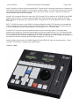
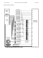
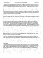
SuperSlide
Instant Replay Control System
Instruction Manual
VERSION: 010622
BUF Technology, 12335 World Trade Drive, Suite 11, San Diego, CA 92128
Telephone: 858-451-1350
www.buftek.com
Fax: 858-451-6589
Version: 010622
SUPERSLIDE INSTRUCTION MANUAL
Page 2 of 19
TABLE OF CONTENTS
INTRODUCTION .......................................................................................................................................................... 4
FCC RADIO FREQUENCY INTERFERENCE STATEMENT ................................................................................ 4
WARRANTY STATEMENT..................................................................................................................................... 4
OVERVIEW ............................................................................................................................................................. 4
PHYSICAL............................................................................................................................................................... 4
INSTALLATION ...................................................................................................................................................... 4
CONTROL PANEL.................................................................................................................................................. 5
SIMPLIFIED BLOCK DIAGRAM ............................................................................................................................ 6
OPERATION................................................................................................................................................................. 7
VR300 CHANNEL SELECTION ............................................................................................................................. 7
CLIPS ...................................................................................................................................................................... 7
RECORDING........................................................................................................................................................... 7
CHILD CLIPS .......................................................................................................................................................... 8
PLAYBACK............................................................................................................................................................. 9
SCAN MODE........................................................................................................................................................... 9
AUTO GPI CONTROL .......................................................................................................................................... 10
SEQUENCE MODE............................................................................................................................................... 10
INSTANT REPLAY ............................................................................................................................................... 10
TRIMMING IN AND OUT POINTS ........................................................................................................................ 11
SETTING IN AND OUT POINTS........................................................................................................................... 11
SETTING TIMECODE NUMBERS........................................................................................................................ 11
SETTING THE CLIP DESCRIPTION.................................................................................................................... 11
PERSONALITY REGISTERS ............................................................................................................................... 12
COLD BOOT ......................................................................................................................................................... 12
MENU.......................................................................................................................................................................... 13
CLIP MANAGEMENT ........................................................................................................................................... 13
IN AND OUT POINT HANDLES ...................................................................................................................... 13
CLIP DATA STORAGE ................................................................................................................................... 13
MENU ITEMS ........................................................................................................................................................ 14
CLIP UTILITIES ............................................................................................................................................... 14
SCROLL CLIPS .......................................................................................................................................... 14
FKEY DESC WORDS................................................................................................................................. 14
DELETE CLIP ............................................................................................................................................. 14
RELOAD CLIPS.......................................................................................................................................... 15
SORT CLIPS............................................................................................................................................... 15
RECORD SETTINGS....................................................................................................................................... 15
RECORD CLIP............................................................................................................................................ 15
TIME OF DAY REC .................................................................................................................................... 15
RECORD START TC.................................................................................................................................. 15
RECORD DURATION................................................................................................................................. 15
REC CH ID CHARS .................................................................................................................................... 15
CHILD SETTINGS............................................................................................................................................ 15
MARK REACTION...................................................................................................................................... 16
PRE-IN HANDLE ........................................................................................................................................ 16
POST-OUT HANDLE.................................................................................................................................. 16
DEFAULT DUR........................................................................................................................................... 16
MAKE CHILD FROM .................................................................................................................................. 16
PERSONALITY REGS..................................................................................................................................... 16
SAVE PERSONALITY................................................................................................................................ 17
RECALL PERSONALITY REGISTER ....................................................................................................... 17
RECALL DEFAULTS ................................................................................................................................. 17
CALCULATOR STYLE # KEYS................................................................................................................. 17
OPER PREFS .................................................................................................................................................. 17
ADJUST SLIDE .......................................................................................................................................... 17
DÉTENTED SLO-MO ................................................................................................................................. 17
Version: 010622
SUPERSLIDE INSTRUCTION MANUAL
Page 3 of 19
QTY OF DÉTENTES................................................................................................................................... 18
MAX FWD SPEED...................................................................................................................................... 18
MAX REV SPEED....................................................................................................................................... 18
MISCELLANEOUS MENU ITEMS .................................................................................................................. 18
VERSION AND TEST ................................................................................................................................. 18
GPI ROLL DELAY ...................................................................................................................................... 18
SET TIME OF DAY ..................................................................................................................................... 18
LED BRIGHTNESS .................................................................................................................................... 18
MENU DISPLAY ANGLE ........................................................................................................................... 18
STATUS DISPLAY ANGLE........................................................................................................................ 18
INITIALIZE UNIT......................................................................................................................................... 19
Version: 010622
SUPERSLIDE INSTRUCTION MANUAL
Page 4 of 19
INTRODUCTION
FCC RADIO FREQUENCY INTERFERENCE STATEMENT
This device complies with part 15 of FCC rules. Operation is subject to the following two conditions: (1) this device
may not cause harmful interference, and (2) this device must accept any interference received, including
interference that may cause undesired operation.
This equipment has been tested and found to comply with the limits for a class A digital device, pursuant to Part 15
of the FCC Rules. These limits are designed to provide reasonable protection against harmful interference when
the equipment is operated in a commercial environment. This equipment generates, uses and can radiate radio
frequency energy and, if not installed and used in accordance with the instruction manual, may cause harmful
interference to radio communications. Operation of this equipment in a residential area is likely to cause harmful
interference in which case the user will be required to correct the interference at his own expense.
Changes or modifications not expressly approved by LEITCH could void the user’s authority to operate this
equipment. Shielded cables must be used with this equipment to maintain compliance with FCC regulations.
WARRANTY STATEMENT
LEITCH warrants that the equipment it manufactures is free from defects in materials and workmanship.
Equipment that has been operated within its ratings and has not been subjected to mechanical or other abuse or
modification and has failed because of such defects, will, at the option of LEITCH, be repaired or replaced if it is
returned, freight pre-paid, to LEITCH within two years from the date of shipment. Equipment that fails under
conditions other than described herein will be repaired at the price of parts and labor in effect at the time of repair.
This warranty is in lieu of all other warranties, express or implied, including, but not limited to, any implied warranty
of merchantability or fitness for a particular purpose. LEITCH is not liable for any consequential damages.
OVERVIEW
The SUPERSLIDE Instant Replay Control System is designed specifically to control Leitch/ASC VR300
Video/Audio Server Systems that use shared media such as a Fibre Channel disk array. Up to ten channels can
be controlled, usually configured as five full-time record channels and five matching playback channels. The
“Platform 1” VR300 has one channel capable of high quality slow motion output complete with vertical “bobble”
cancellation, and one channel suitable for record purposes. The SUPERSLIDE provides a simple means for
putting record channels into a loop record mode, usually using time of day timecode. Playback is controlled on
matching playback channels in a way that allows frame accurate simultaneous playback of multiple channels and
GPI control that inherently lets the Technical Director choose which channel(s) to roll, and when to roll them.
PHYSICAL
The SUPERSLIDE control panel requires only ten inches width by eight inches depth of console space, and has a
sloped control surface for easy user access. Two backlit alphanumeric displays separate clip and menu operations
from status and timecode display. Playback control is always instant regardless of where the operator may be in
the menu system. The playback control keys are placed within easy reach of the high quality optical encoded
knob. The Slide, implemented using a motorized linear fader, is used for speed control. A numeric keypad allows
quick entry of timecode and random access clip selection. A MAKE CHILD key creates one or more child clips
(subclips) from record or playback clips.
The RM-4000-L Remote Processor rear panel includes ten separate DB9F connectors for connection to ten
channels of VR300, a power supply connection, a DB15F GPI connector, and two RJ45 8-pin modular telephone
connectors for connection to the control panel.
INSTALLATION
Install the RM-4000-L into an equipment rack and connect the included power supply. Connect the control panel
and Slide to the RM-4000-L via the included 15 foot RJ45 cables. Longer cables may be used, but the maximum
length is restricted to about 50 feet (15 meters) by voltage drop from the power supply (9.5VDC minimum at the
Version: 010622
SUPERSLIDE INSTRUCTION MANUAL
Page 5 of 19
panel). Normally, the cables should be prepared RJ45 “Telephone style”, where the connectors are crimped on the
same surface of the cable resulting in a reversal of the conductor order. CAT-5 “Data style” cables may be used by
connecting the Slide to the PANEL connector, and the panel to the SLIDE connector. Improper connection will
prevent operation but will not cause damage.
Make RS-422 connections from one or more of the VTR-1 through VTR-10 connectors to VR300 REM1 and REM2
remote control connectors. Pin-for-pin male-male DB9 cables should be used (see note). Normally, VR300 #1
REM2 should be connected to VTR-1, REM1 should be connected to VTR-6, VR300 #2 REM2 to VTR-2, REM1 to
VTR-7, etc.
NOTE: The REM1 connector on the VR300 is normally configured to control a VTR rather than be controlled and
must be reconfigured (a) by changing jumper links inside the unit (this is a difficult task due to mechanical issues),
or (b) by crossing pins 2/8 and 3/7 in the cabling. Only conductors 2, 3, 4, 7 and 8 are used.
The DB15F GPI connector connects to production switcher (vision mixer) tally outputs. These tallies allow
playback to be rolled by the Technical Director simply by punching up a playback view. Pins 1-10 control channels
1-10 (channels connected to VTR-1 through VTR-10 connectors), and pin 15 is common Ground. The GPI input
pins are active low with a threshold of approximately +2.5 volts, are pulled up to +5 volts through 10K resistors, and
can withstand continuous externally applied voltages ranging from -25 to +35 volts.
Various settings must be made in the VR300 Registry for the SUPERSLIDE system to operate properly. Contact
Leitch/ASC for assistance in preparing your VR300 system.
CONTROL PANEL
Version: 010622
SUPERSLIDE INSTRUCTION MANUAL
Page 6 of 19
SIMPLIFIED BLOCK DIAGRAM
SUPERSLIDE
CONTROL
PANEL
SUPERSLIDE
RM-4000-L 6
(1RU) 1
7
2
RS422 8
PORTS 3
9
4
10
5
GPI
CAM 1
IN
CAM 2
IN
CAM 3
IN
CAM 4
IN
CAM 5
IN
IN A OUT
VR300 #1
B OUT
R1
P1
PRODUCTION
SWITCHER
(VISION MIXER)
IN
IN A OUT
VR300 #2
B OUT
R2
P2
IN
IN A OUT
VR300 #3
B OUT
IN A OUT
VR300 #4
B OUT
R3
P3
R4
IN
P4
IN
HIGHLIGHTS
EDITING
STATION
NLE
IN A OUT
VR300 #5
B OUT
IN A OUT
VR300 #6
B OUT
FIBRE CHANNEL
DISK ARRAY
CONNECT TALLIES FOR PLAYBACK CH’S 1-5 TO PINS
1-5 ON DB15M CONNECTOR FOR GPI, GND TO PIN 15
R5
P5
SLO-MO
OPERATOR
MONITORS
IN
IN
TALLY OUTPUTS
Version: 010622
SUPERSLIDE INSTRUCTION MANUAL
Page 7 of 19
OPERATION
VR300 CHANNEL SELECTION
VR300 channels are selected for control using the function keys F1-F10. The currently selected channel is
indicated by the green LED lighted above its F-key. A double-tap of an F-key enters the gang mode, allowing
multiple channels to be controlled together. While in the gang mode, indicated by one or more green LEDs
flashing, channels are added to or removed from the gang by holding HOME and tapping F-keys. The MASTER
channel is indicated by a longer flashing green LED vs SLAVES indicated by a shorter duty-cycle flash. The main
difference between the MASTER and SLAVES is that the status display always shows the loaded clip, timecode,
and status of the MASTER channel. A SLAVE is changed to the MASTER by tapping its F-key. To exit the gang
mode and go back to independent control of a single channel, tap an F-key that is not in the gang (no green LED),
or double-tap the F-key that was used to enter the gang.
CLIPS
Clips can be displayed, modified, sorted, and reloaded using the menu display and menu system. Data for up to
500 clips are automatically loaded into memory in the SUPERSLIDE panel when it is connected to the RM-4000
and channel 1 on the RM-4000 is connected to a VR300. Clips are loaded at a rate of about one per second, so if
many clips exist, it may take several minutes for all clips to be loaded. You can check if all clips are loaded by
tapping HOME, 999, ENTER and keep hitting the RIGHT arrow key until the clip shown on the menu display stops
incrementing. Once all clips have been loaded, you may want to alphabetize them using the CLIP UTILITIES,
SORT CLIPS menu. If any clips have been deleted by VR300 user stations, including a complete wipe of the
disks, use the CLIP UTILITIES, RELOAD CLIPS menu to clear the panel’s memory and restart loading clips.
Otherwise, deleted clips will continue to show on the panel, but attempts to load them will fail. Clips that are
deleted using the CLIP UTILITIES, DELETE CLIP menu are removed from panel memory.
Any clip can be loaded into any selected channel simply by selecting a clip onto the menu display and tapping
LOAD CLIP. To select clips sequentially, use the LEFT/RIGHT arrow keys to decrement/increment until you see
the desired clip name and description on the menu display. To randomly select a clip, tap HOME, enter the clip’s
index number on the numeric keypad and tap ENTER. To recall the selected channel’s currently loaded clip into
the menu display, tap HOME, then ENTER. The index number used to call up a clip randomly is set arbitrarily,
based on the order that they are reported by the VR300. The CLIP UTILITIES, SORT CLIPS menu item sorts them
alphabetically; otherwise the numbers never change and can be noted to facilitate quick recall at any time. If an
icon of a child is shown in the upper right corner of the menu display, first double-tap HOME to remove it before
recalling a clip by index number (see CHILD CLIPS below). Tap HOME, zero, then ENTER to recall the parent of
the last used child mode, then double-tap HOME to reenter the child mode.
When a clip is loaded into a channel using LOAD CLIP, the clip’s first frame is output from that channel. Since
each output channel is input to the production switcher and an accompanying monitor, all loaded clips are viewable
by the Director. If you have AUTO enabled and are in PLAY, as soon as the Director asks the Technical Director to
put any channel on-air, it will roll automatically, eliminating wrong channel rolling errors and insuring perfect
synchronization between going on-air and rolling. If AUTO is off, the clip will play when PLAY is tapped or if the
SLIDE is moved from the still position, whether or not it is on-air. If AUTO is enabled, the clip will play only during
the time the channel is on-air, and will cue and remain cued to the first frame when offline.
RECORDING
The RECORD SETTINGS menu allows you to set the RECORD CLIP base name, enable/disable TIME OF DAY
REC or set the RECORD START TC, set the looping RECORD DURATION, and assign REC CH ID CHARS. Only
the first three characters of record clips are used to identify a particular session, so try to use unique characters in
these places. The fourth character is used as a record instance counter and should be set initially to the numeral 0.
Each time a recording is begun, this character is incremented, resulting in sequential record clip names that will
sort properly. The last character in the record clip name is used to identify the channel that made the recording. If
multiple channels are put into record simultaneously, as is usually the case, the first seven characters of the record
clips are the same and only the eighth (last) character is unique. These channel identification characters can be
changed using the REC CH ID CHARS menu and default to A-E for channels 6-10, F-J for channels 1-5.
Characters 5-7 should not be set to anything important because child clips are named by replacing these
characters with three-digit numbers that increment each time a child is made.
Version: 010622
SUPERSLIDE INSTRUCTION MANUAL
Page 8 of 19
A looping record clip is always used and is set to the duration set in the RECORD DURATION menu; default is 30
minutes. Looping record means that after the record duration has been recorded, the system then begins to
release and reuse disk space. As child clips are made, their disk space is protected and will not be reused until
they are deleted. When restarting a recording, a new record clip is made for each record enabled channel, with a
unique name created by incrementing the fourth character. This means that each new recording session will
consume another 30 minutes (default) of disk space per record enabled channel! It is best, therefore, to leave the
record channels in record, and make child clips to preserve any recorded material that you wish to save. Parent
clips cannot be deleted, but the disk space occupied by them that is not preserved by child clips can be released
using a VR300 workstation. A shorter record duration saves disk usage, but reduces the time you have to make a
child.
Hold the REC key in to view the free disk space and the current record clip name on the status display (the fourth
character will be incremented before a new recording is begun). Also, the enabled record channels are indicated
while holding REC by the red LED lighting above their F-keys. A flashing red LED indicates a record enabled
channel that is not responding or connected. To enable/disable record channels, tap F-keys while holding the REC
key. Recording is commenced on all record enabled channels exactly three seconds after REC is held and PLAY
is tapped, regardless of which channels are selected for playback. Channels that are in record are indicated by a
lighted red LED above their F-keys. If TIME OF DAY REC is enabled (the default), an internal clock sets the
starting timecode of the record clips to the time of day which is set in the MISCELLANEOUS MENU ITEMS, SET
TIME OF DAY menu. The time of day clock is NOT maintained while power is off and must be reset each time the
SUPERSLIDE is restarted.
All recording channels may be taken out of record mode at any time by holding REC and tapping STOP. A warning
message (STOP RECORD ALL CHANNELS? ENTER) is displayed and must be responded to by the ENTER key
to stop recording, or any other key will cancel the operation.
CHILD CLIPS
Child clips, or subclips, are portions of parent clips, can be loaded and played by the SUPERSLIDE just as any
other clip, and are available to VR300 workstations. Whenever a child clip is shown on the menu display and the
system is in gang mode, siblings are searched for and are loaded into the same channels that created them. This
allows simultaneous loading of different views of the same action. Siblings are child clips that have the same first
seven characters of their names; the last character identifies the channel that made the parent, the first four
characters are the same as the parent’s name, and characters 5-7 are the child sequence number. When child
clips are created by the SUPERSLIDE, an “owner” character is stored in the VR300 with each child clip that
controls which channel each sibling will load into when in gang mode. When not in gang mode (solid, not flashing,
green LED), the child shown will be loaded into the selected channel; this allows cross-channel loading of clips.
Child clips are indicated on the menu display by a trailing period character after the clip name. Parent clips (clips
that have one or more children), are indicated by a trailing colon. Whenever a child or parent is shown on the
display, a double-tap of the HOME key enters the child mode where clip selection is limited to only the parent and
its children. This makes it easy to step up and down through successive replay clips. The child mode is indicated
by a child shaped icon in the upper right corner of the menu display. While in the child mode, randomly selecting
clips with the numeric keypad and ENTER key select the clip with the sequence number (characters 5-7) that
matches the number entered. Zero followed by ENTER selects the parent. Another double-tap of HOME exits the
child mode. To reenter the last used child mode at any time, tap HOME, zero, ENTER, and double-tap HOME.
Tap the MAKE CHILD key to create one or more child clips (subclips). If in gang mode, a child clip is made for
each enabled channel; these are called siblings. Normally, the child clips for playback channels are made from
each matching record channel’s in-record clip. The CHILD SETTINGS, MAKE CHILD FROM menu changes which
channel’s clip each channel will use for the parent clip when making children. A child clip can be made from the
currently loaded clip on the same channel by holding ENTER while tapping MAKE CHILD. If a child is made from
another child, it will actually be made from the parent of the child; it will not be a grandchild.
If multiple channels are in record, and MAKE CHILD is tapped while in the gang mode with matching playback
channels enabled, child clips will be made for each camera angle being recorded. The LOAD CLIP key then loads
all these sibling clips into their respective channels, which all park at the first frame. Turn the KNOB to jog and tap
Version: 010622
SUPERSLIDE INSTRUCTION MANUAL
Page 9 of 19
TRIM IN to change the first frame on all enabled channels’ child clips. If the channels become out of synch while
jogging, the IN point will be taken from the MASTER channel, and all SLAVE channels’ child clips will be trimmed
the same; a subsequent tap of the CUE key brings them back into synch. Tap the PLAY key to play the clips in
synch, or move the SLIDE up from the still position to play, in synch, in slow motion.
To conserve disk space, a loop record mode is used. This means that after a preset duration (set in the RECORD
SETTINGS, RECORD DURATION menu), the beginning of the recording is reused and recorded over. Child clips
are preserved, and will not be erased, along with safety handles that allow subsequent trimming the IN point earlier
and/or trimming the OUT point later (the handle durations can be changed in the CHILD SETTINGS menu). Even
after disk reuse results in child clips no longer being actual subsets of their parents, the child is still considered as
belonging to the parent to help keep things organized.
PLAYBACK
Playback is controlled by the PLAY, STOP, and SLOW keys and by The Slide. When playback speed is set using
these keys or is set to still by a LOAD CLIP or CUE operation, The Slide is automatically moved to the correct
position by its built-in motor. Speed can then be changed smoothly by moving The Slide. When you select a
different channel, The Slide moves into the position that was last used with that channel. Mechanical breakpoints
are felt on The Slide when moving it to the still, play, and reverse play positions; this tactile feedback keeps the
operator informed about The Slide’s position. A spring-like feel is felt above the play speed breakpoint, between
the still and reverse play breakpoints, and below the reverse play breakpoint. Pushing The Slide against the
spring-like resistance above the play breakpoint proportionally varies speed between 100% and the speed set in
the OPER PREFS, MAX FWD SPEED menu. Pushing below the reverse play breakpoint proportionally varies
speed between -100% and the speed set in the MAX REV SPEED menu. Additional tactile feedback in the form of
speed détente steps between still and play are added by enabling the OPER PREFS, DÉTENTED SLO-MO menu
item. In this mode, playback speed is changed in discrete steps that are selected for the least perceivable temporal
distortion (a.k.a. judder). The number of détentes can be changed using the OPER PREFS, QTY OF DÉTENTES
menu. Eventually, SUPERSLIDE operators subliminally count détentes and always know by feel what speed they
are at.
The PLAY key rolls the loaded clip at 100% play speed and moves The Slide to the play breakpoint position. The
STOP key brings playback to a still frame and moves The Slide to the still breakpoint. The SLOW key plays the
loaded clip at the speed stored with the clip and moves The Slide to the correct position for that speed. If détented
mode is enabled and the recalled speed is not a détente speed or SLOW is double-tapped, the non-détented mode
is used temporarily. PLAY, STOP, or SLOW restores the détented mode. Hold ENTER and tap SLOW during
playback to store the current playback speed with the clip.
While at still, turning the KNOB jogs through the material between -100% and 100% speeds. If at the IN or OUT
points and at still (00% showing on the status display), the KNOB will jog into the IN and OUT handles, if they exist,
all the way to the clip’s actual IN and OUT points (see CLIP MANAGEMENT, IN AND OUT POINT HANDLES).
You can tap CUE to go to the IN point at still, turn the KNOB counterclockwise to roll into the IN point handle, and
tap TRIM IN to move the IN point earlier into the clip, hence reclaiming material before the old IN point. Double-tap
STOP, move The Slide to its upper limit, and tap STOP to cue to the OUT point. You can then extend the end of
the clip (if an OUT handle exists) by turning the KNOB clockwise and tapping TRIM OUT.
SCAN MODE
Clips can be scanned from head to tail using the scan mode. Double-tap the STOP key to enter the scan mode;
playback stops and The Slide moves to a position proportional to where the clip is parked between its IN and OUT
points. Move The Slide up and down to scan the entire clip as fast as you move it. If in gang mode, all ganged
channel’s clips scan together. Tap STOP or PLAY to resume normal operation where the scan mode left off. If
PLAY is used to exit the scan mode, there will be a delay before the clip begins to roll; you can avoid this delay by
using STOP to exit scan and waiting a short period before tapping PLAY. Clips may be trimmed while in the scan
mode. Because clips are stored with handles that allow trimming before the IN point and after the OUT point, there
is an extended scan mode. Hold ENTER while tapping STOP. Now The Slide will scan the entire clip including its
handles, and trimming can be done to extend the clip’s limits.
Version: 010622
SUPERSLIDE INSTRUCTION MANUAL
Page 10 of 19
AUTO GPI CONTROL
If in AUTO mode (AUTO LED lit), the channels will not play until one or more GPI goes active (by being taken onair at the switcher). Only those channels whose GPIs go active will roll, the others remain cued until their GPIs go
active or until they are taken out of AUTO mode. A flashing AUTO LED indicates that some enabled gang
channels are in AUTO and others are not. If two or more channels are selected on a switcher mix/effects bus,
when that M/E is taken on-air, both channels will roll in synch even while speed is changed via The SLIDE as long
as speed remains within the 0-100% range. To roll or cue channels offline, they must be taken out of AUTO (tap
the AUTO key to toggle the AUTO mode). You can jog (with the KNOB) and trim while AUTO is enabled, but
LOAD CLIP must be tapped before the trim takes effect.
SEQUENCE MODE
The SEQ mode, indicated by the SEQ LED, allows the same clip to be looped indefinitely, or multiple clips to be
played sequentially with seamless, frame accurate transitions from one clip to the next. If, while playing a loaded
clip, the SEQ mode is activated by tapping the SEQ key, the LOAD CLIP key prepares the selected clip (shown on
the menu display) to begin playing after the current clip reaches its last frame. If a child clip is used in gang mode,
and siblings exist (see CHILD CLIPS), then all enabled playback channels will act the same as the master, except
each will transition to its own sibling clip. If LOAD CLIP is not used to pre-load another clip, the last clip that was
loaded while in SEQ mode will loop forever. A flashing SEQ LED indicates that some enabled gang channels are
in sequence mode and others are not.
INSTANT REPLAY
The following scenario assumes a five VR300 Fibre Channel disk array system as shown in the SIMPLIFIED
BLOCK DIAGRAM on page 6. All settings are set to default (PERSONALITY REGS, RECALL DEFAULTS menu).
Channels 1-5 are enabled in gang mode (double-tap F1, hold HOME and tap F-keys until green LEDs 1-5 are
flashing). Channels 6-10 were put into record at the same time (hold REC, tap PLAY) using time of day timecode
(set in the MISCELLANEOUS MENU ITEMS, SET TIME OF DAY menu). The AUTO LED is lit (tap AUTO key):
Watch the record channel monitors and when you see action worthy of replay, count two seconds and tap MAKE
CHILD, then tap LOAD CLIP. Five different camera angles of the same moment in time appear on the replay
channel monitors. If you don’t think the moment shown is a good place to start the replay, turn the KNOB to a
better point and tap TRIM IN then LOAD CLIP. Tap the AUTO key and set The Slide to a good speed. Optionally,
tap the TRIM OUT key to set a point where replay should stop; otherwise, the child clip will end at the default
duration point (30 seconds unless changed in the CHILD SETTINGS, DEFAULT DUR menu). Tap AUTO again to
light the AUTO LED; the clips re-cue. When the T.D. punches-up a replay channel, it plays, and you can ride
speed with The Slide. As the T.D. transitions to another view, that channel will begin to roll at the same speed
while the first channel tails-out. As soon as the first channel goes off-air, it re-cues in case the Director wants to
show it again. You have the freedom to set different IN and OUT points for each view by exiting the gang mode
and trimming channels separately (however, this prevents the possibility of rolling multiple views in synch). You
can enter a clip description that helps VR300 user station operators identify clips by tapping CLIP DESC, F-keys
(with words stored in them) and/or number keys, then ENTER (see SETTING THE CLIP DESCRIPTION).
Remember:
1. Put all record channels into record at the same time so MAKE CHILD in gang mode makes siblings.
2. Keep all playback channels selected in gang mode and in AUTO.
3. Tap MAKE CHILD only when you see something worth replaying, then tap LOAD CLIP.
4. Test playback speed by tapping AUTO, then tap it again to reenter the AUTO mode and re-cue.
5. Let the T.D. roll the channels; just ride the speed.
6. While a replay is pending or playing, you can make more child clips if more worthy action happens.
7. You can trim the IN point, even while in AUTO, by turning the KNOB and tapping TRIM IN.
8. You don’t have to worry about rolling off the end of a recording because you are always in record!
9. You can set an OUT point if you want playback to still frame on key action.
10. Once the OUT point is reached, you can play after it by tapping STOP and turning the KNOB.
To prepare a preloaded clip for playback at the Director’s pleasure:
1. Remove a playback channel from the gang (hold HOME and tap its F-key).
2. Tap the channel’s F-key to exit the gang mode and select the channel independently.
Version: 010622
SUPERSLIDE INSTRUCTION MANUAL
Page 11 of 19
3. Select the clip on the menu display and tap LOAD CLIP.
4. Tap AUTO and PLAY to test play the clip.
5. Tap AUTO to re-cue the clip, 100% should still show on the status display.
6. Reenter the gang to go back to looking for replay action as usual (except less one channel).
7. Whenever the T.D. takes the channel on-air, it will roll without you having to do anything.
This allows you to keep your attention on the action, provides the Director with a still frame view of the first frame of
the preloaded clip, and gives the T.D. absolute control over when to play it. All other channels are still available for
replay functions.
There are several habits that should be avoided:
1. To avoid clogging up the system with too many child clips, don’t tap MAKE CHILD until you are sure you have
seen something worthy. Since there is a lead time, you don’t have to anticipate when something might happen
and keep marking it. As you hit MAKE CHILD, it operates retroactively, with the first frame marked two
seconds ago (the two seconds can be changed in the CHILD SETTINGS, MARK REACTION menu).
2. Avoid stopping recording, ever, it wastes disk space. Because looping record clips that minimize disk usage
are used, there is never an advantage to stop recording. A nice side benefit of this is that you will never miss
anything that happens when you least expect it; and you can make one or more child clips to preserve it.
3. If you have GPI interface from the switcher tallies, avoid rolling clips manually on-air. Roll them manually to
check, trim, and decide on an appropriate speed, then tap AUTO to recue them and let the Technical Director
roll them simply by punching them up. This avoids accidentally rolling the wrong channel, allows in synch split
screen playback, and insures perfect timing of the first frame you trimmed being the first frame on-air.
TRIMMING IN AND OUT POINTS
The TRIM IN and TRIM OUT keys change the loaded clip’s first and last frames, respectively, to the current
playback position. The IN point is the frame that is output after a LOAD CLIP or CUE operation; the OUT point
defines where normal or slow speed playback comes to a still frame. Usually, the clip is not actually changed,
instead, offset values are stored with the clip in the VR300 that tell the SUPERSLIDE where the “virtual” IN and
OUT points are. The exception to this is when trimming a child clip that is still a subset of its parent. In this case,
the child is actually trimmed (smaller or larger), but the default handles (which can be changed in the CHILD
SETTINGS menu) are preserved for subsequent trimming after the child is no longer a subset of the parent.
SETTING IN AND OUT POINTS
IN and OUT points can be set explicitly, but affect the clip shown on the menu (left) display rather than the loaded
clip (shown on the status display) as do TRIM IN and TRIM OUT. You can select the loaded clip into the menu
display by tapping HOME, ENTER. Tap HOME, then IN (UP arrow) to set the IN point, OUT (down arrow) to set
the OUT point, or OUT again to set the OUT point by duration. When setting IN and OUT points, only the offset
pointers are actually changed as described in TRIMMING IN AND OUT POINTS, so the amount the numbers can
be changed is limited. If you want to change IN and OUT points by large amounts, it is better to make a child, and
then set the IN and OUT points of the child. Whenever you want to change an IN or OUT point of a child clip by a
large amount, use this method rather than TRIM IN or TRIM OUT.
SETTING TIMECODE NUMBERS
All timecode values in the system are set the same way using the numeric keypad. When you first begin setting a
register, its existing value is shown on the display. As you enter the first digit, the display is reset to zeros and the
key’s value shows as units of frames (or as units of seconds when setting registers that do not use frames). Each
digit entered shifts the displayed digits to the left. The HOME, SETUP, UP arrow, DOWN arrow and MAKE CHILD
keys cancel the operation, leaving the register unchanged. The ENTER key replaces the register with the
displayed timecode numbers. The RIGHT/LEFT arrow keys act the same as ENTER except they “trim” the register
value instead. The RIGHT arrow key (trim up) adds the displayed timecode numbers to the existing register value.
The LEFT arrow key (trim down) subtracts the displayed timecode numbers from the existing register value.
SETTING THE CLIP DESCRIPTION
A 24 character description of each clip is shown on the lower line of the menu display after using the HOME key.
Since the display line is 16 characters long, only the first 16 characters are shown; hold HOME to show the last 16
characters. The description also appears on VR300 workstations to help identify clip contents. Ten preset words
Version: 010622
SUPERSLIDE INSTRUCTION MANUAL
Page 12 of 19
can be loaded into the ten F-keys using the CLIP UTILITIES, FKEY DESC WORDS menu item. It is best to use
short informative words like “GOAL”, “HIT”, etc. When the CLIP DESC key is tapped, the clip currently playing on
the selected channel (and shown on the status display) is recalled into the menu display with the description field
blocked out. As F-keys are tapped, the words stored in them appear in the description. Numeric keypad keys can
be used to enter numbers into the description. Spaces are automatically placed between F-key words and number
sequences. Tap ENTER to store the description in the VR300 database, or HOME to cancel.
PERSONALITY REGISTERS
The SUPERSLIDE is equipped with ten personality registers. There are many user adjustable settings in the
system, most of which can be stored in personality registers. Saved personality configuration data are protected by
an error detection value. When the unit is reset, even if a Cold Boot (see below) is performed, Any personality
registers that check out OK are preserved. Once you have configured the unit for how you like to work, you can
store the configuration in a personality register and name it as you desire. You can recall a register anytime in the
future to restore operation to the way you like it.
COLD BOOT
If for any reason, you wish to reset the SUPERSLIDE back to the factory preset configuration, a “COLD BOOT”
may be performed. This operation erases all events, and some internal registers; personality registers are not
affected. A cold boot is accomplished by unplugging the modular cable from the rear of the panel, and holding the
MAKE CHILD and PLAY keys down while plugging the cable back in.
Version: 010622
SUPERSLIDE INSTRUCTION MANUAL
Page 13 of 19
MENU
Many operational settings are adjustable by using the menu system. A separate MENU display is used so that
playback controls and status/timecode display are always active, even while navigating the menu. There are two
exceptions to this: Some menu items use the KNOB, so it can not jog while in such a menu item. Tap HOME to
restore normal KNOB function. The other exception is the MISCELLANEOUS MENU ITEMS, VERSION AND
TEST menu. It includes a keyboard test that prevents keys from operating. Turn the KNOB to end the keyboard
test.
The basic menu functions are:
CLIP MANAGEMENT Provides quick access to the most used clip functions.
MENU ITEMS A comprehensive set of user settings and operations.
CLIP MANAGEMENT
No matter where you are in the menu system, tapping the HOME key returns to the CLIP MANAGEMENT menu
item. There is memory for up to 500 clips that are automatically loaded from the VR300 channel that is connected
to channel 1 (VTR-1 connector on the RM-4000). If the CLIP UTILITIES, RELOAD CLIPS menu item is used while
a channel other than channel 1 is enabled, that channel will be used to maintain the clip database. Each clip
contains the clip name, clip description, IN point, OUT point, IN point offset, OUT point offset, slow speed memory,
and owner channel indicator. The clip name is used to identify the clip, and is necessarily unique for each clip.
Index numbers are used to access clips randomly, and remain constant unless clips are sorted or deleted at the
SUPERSLIDE panel. The clip description is a 24 character description that shows on the lower menu display line
when HOME has been tapped. A limited number of clip descriptions are cached in the panel, so when scrolling
through many clips, there will be a short delay before the description becomes visible.
IN AND OUT POINT HANDLES
IN and OUT point handles are preserved before and after the SUPERSLIDE IN and OUT points to allow clips to
be lengthened at the SUPERSLIDE panel, and to give VR300 user stations access to that material. When IN
and OUT points of normal (non-child) clips are trimmed or set, the clip is not actually changed, instead an offset
number is adjusted in the VR300 database that points into the clip. This allows trimmed material to be
reclaimed later. Loading clips, cueing, and playback at the SUPERSLIDE use these points as though they were
the actual IN and OUT points, but jogging with the KNOB while in still mode will enter into the handles, allowing
a clip to be trimmed longer. When a clip is used by VR300 software, the entire clip, with handles, is used
because the VR300 doesn’t recognize the offsets. These numbers are viewable (see CLIP DATA STORAGE),
so an operator at a VR300 user station can see what the SUPERSILDE operator had in mind. When a VR300
operator assembles a highlights reel, he has access to the material in these handles, giving him the freedom to
use events just prior to and/or just after the footage that was actually used during replay.
Child clips are handled the same way except that if the child is still a subset of its parent, trimming sets the
offsets to the default child handles (see CHILD SETTINGS), and the actual IN and OUT points are adjusted. If
there is not enough material in the parent to do this, the offset is adjusted shorter and/or the IN or OUT point is
adjusted to achieve the best compromise possible. When child clips are trimmed in gang mode, and there are
sibling clips loaded into other enabled channels, trimming will affect all the siblings according to the master
channel’s clip.
CLIP DATA STORAGE
IN and OUT point offsets, slow motion speeds, and owner indicators are stored in the “Agency” field of the
VR300 database in the form “i0000 o0000A000”, and can be changed at any ASC workstation if desired. The
SUPERSLIDE maintains these data automatically and transparently to the user. Because the data is stored in
the VR300, an empty SUPERSLIDE will restore all this information from the VR300. The i0000 field is a four
digit IN point offset, in frames, with a maximum offset of 9999 frames (max just over 5½ minutes). This is the
offset into the actual beginning of the clip that the SUPERSLIDE uses to cue to whenever the clip is loaded into
a channel (using the LOAD CLIP key), or any time the CUE key is used. The OUT point offset is stored in the
form o0000, and is a four digit offset back into the clip from its actual end point. Playback at normal or slow
speed will stop on the frame specified by this offset. The scan mode scans the clip between the offset IN and
Version: 010622
SUPERSLIDE INSTRUCTION MANUAL
Page 14 of 19
offset OUT points unless extended scan is used (see SCAN MODE). The last three numbers in the agency field
specify the slow motion speed in percent of play speed. Anytime a clip is rolling, hold ENTER and tap SLOW to
store the current speed. Whenever the SLOW key is used to play a clip in slow motion, this speed is recalled
and The Slide is moved to the proper position for subsequent manual speed adjustment. The fourth to last
character is the owner channel indicator; A-J is used to indicate channels 1-10 respectively. When loading child
clips in gang mode, this owner data is used to control which sibling clips (named with the same first seven
characters) get loaded into which channels.
Instructions for using the CLIP MANAGEMENT functions are in the previous section.
MENU ITEMS
MENU ITEMS contains numerous submenus that allow a multitude of operational settings to be modified according
to the user’s preferences. Tap the SETUP key to enter the menu system, use the UP/DOWN arrow keys to move
between menu items, and the RIGHT arrow key to select a menu item.
The submenus available in MENU ITEMS are:
CLIP UTILITIES
RECORD SETTINGS
CHILD SETTINGS
PERSONALITY REGS
OPER PREFS
MISCELLANEOUS MENU ITEMS
CLIP UTILITIES
A submenu containing these items:
SCROLL CLIPS
FKEY DESC WORDS
DELETE CLIP
RELOAD CLIPS
SORT CLIPS
SCROLL CLIPS
Scrolls through all loaded clips using the KNOB.
FKEY DESC WORDS
Sets words of up to eight characters in length into each of the ten F-keys for use in setting clip descriptions
(see SETTING THE CLIP DESCRIPTION). While in this menu item, tap an F-key to select the F-key word to
view and change. A cursor appears under the first character of the word; change this character by turning
the KNOB. Use the LEFT/RIGHT arrow keys to move the cursor to other characters. A dotted underline
character indicates an empty character and can be selected by turning the KNOB fully counterclockwise. To
keep words short, enter characters into the first few positions and leave the remainder of the word empty; do
not add separating spaces as they are added automatically. Tap ENTER or another F-key to store the
changes, HOME to cancel.
DELETE CLIP
Deletes the currently selected clip from both the VR300 and the SUPERSLIDE databases. If clips are
deleted using VR300 software, the RELOAD CLIPS menu item must be used to update the SUPERSLIDE
database. In either case, the index numbers that identify the clips will be changed.
Version: 010622
SUPERSLIDE INSTRUCTION MANUAL
Page 15 of 19
RELOAD CLIPS
Clears all clip memory in the SUPERSLIDE and begins to reload clips from the currently selected VR300
channel. After using this menu item, this channel will be used for all clip data recall. The index numbers
used to identify and randomly access clips will be reordered arbitrarily. Use this menu item to bring the
SUPERSLIDE database up to date after making significant deletions using a VR300 user station or after
connecting to a different VR300 system. Clips added or changed using VR300 software will be updated in
the SUPERSLIDE without need to use this menu item. It can take several minutes to reload all clip data
from a VR300 system.
SORT CLIPS
Alphabetizes all clips in the SUPERSLIDE by name. This function reorders the index numbers for the clips
currently in memory, but unloaded and new clips will be added at the end of the index number sequence as
they are loaded from the VR300. If index numbers are noted and used for random access of clips during a
session, it is important not to use the SORT CLIPS, RELOAD CLIPS, or DELETE CLIP menu items.
RECORD SETTINGS
A submenu containing these items:
RECORD CLIP
TIME OF DAY REC
RECORD START TC
RECORD DURATION
REC CH ID CHARS
RECORD CLIP
Sets the base name that will be used for future record operations. See RECORDING for important
information regarding the way record clip names are used. See FKEY DESC WORDS for instructions on
setting alphanumeric entries.
TIME OF DAY REC
Enables/disables the use of time of day timecode for record operations. If enabled (the default), time of day
timecode is used during recording. The MISCELLANEOUS MENU ITEMS, SET TIME OF DAY menu item
must be used to set time of day any time the SUPERSLIDE panel is powered up.
RECORD START TC
Sets the starting timecode number to be used for recording if the TIME OF DAY REC menu item is disabled.
RECORD DURATION
Sets the duration (default 30 minutes) that record clips will record before the sliding record feature reuses
disk space. The record duration is a tradeoff between disk usage efficiency and the amount of time that can
elapse before a child clip can be made from an in-record clip.
REC CH ID CHARS
Sets the character that is used to identify uniquely record clip names for each channel. This character is
used as the last (eighth) character of record clip names. They default to A-E for channels 6-10 (the channels
normally used for recording) and F-J for channels 1-5 (not normally used for recording).
CHILD SETTINGS
A submenu containing these items:
MARK REACTION
Version: 010622
SUPERSLIDE INSTRUCTION MANUAL
Page 16 of 19
PRE-IN HANDLE
POST-OUT HANDLE
DEFAULT DUR
MAKE CHILD FROM
MARK REACTION
Sets the reaction time between when you see action you want to preserve by making a child clip and when
you need to tap the MAKE CHILD key. When MAKE CHILD is hit, the MARK REACTION is subtracted from
the current record clip position to create the child clip’s IN point.
PRE-IN HANDLE
Sets the amount of material that is preserved before the IN point when a child clip is made. When a child
clip is used by VR300 software, it will load and play from the (SUPERSLIDE’S) IN point less the IN point
handle. The IN point handle is stored in the VR300 agency field as the IN offset. See CLIP MANAGEMENT
for more information.
POST-OUT HANDLE
Sets the amount of material that is preserved after the OUT point when a child clip is made.
DEFAULT DUR
Sets the default duration that is used when making child clips using the MAKE CHILD key. This is the
duration between the SUPERSLIDE IN and OUT points; the actual clip duration will be the DEFAULT DUR +
the PRE-IN HANDLE + the POST-OUT HANDLE. Subsequent trimming or setting the IN and OUT points
will affect the actual child duration if the child is still a subset of its parent.
MAKE CHILD FROM
Specifies the channel whose loaded clip the currently selected channel will use as the parent clip when a
child clip is made. Normally, child clips are made from matching in-record channel clips so these settings
default to channels 6-10 (record channels) used to make children for channels 1-5 (playback channels).
Sometimes it is desirable to make a child clip from the clip loaded on the same channel, this is done by
holding the ENTER key while tapping the MAKE CHILD key. If a child is made from an existing child, the
existing child’s parent clip is actually used as the parent, but the IN point is still taken from the existing child’s
currently output frame less the MARK REACTION.
PERSONALITY REGS
A submenu containing these items:
SAVE PERSONALITY
RECALL PERSONALITY REGISTER
RECALL DEFAULTS
CALCULATOR STYLE # KEYS *
* The numeric keypad style is never erased even by a COLD BOOT or the INITIALIZE UNIT menu.
Many aspects of the way the SUPERSLIDE works are adjustable by the user. Almost all of these settings are
stored in registers called personality registers. Ten personality registers are provided, allowing different users to
store their favorite configurations. A user may wish to use two or more registers to recall different modes of
operation depending on the task currently being undertaken. Registers may be named with alphanumeric
names up to sixteen characters long. Items stored in the personality registers include those set in the RECORD
SETTINGS, CHILD SETTINGS, and OPER PREFS menus.
Version: 010622
SUPERSLIDE INSTRUCTION MANUAL
Page 17 of 19
SAVE PERSONALITY
Saves the current configuration in a personality register. Tap numeric keypad keys after selecting this item
to show the names of the various registers. Tap ENTER when an unused register is seen (indicated by the
name DEF for default). You may enter any 16 character name you wish by using the KNOB to select a letter
or number, and the RIGHT and LEFT arrow keys to move to other character positions (the name defaults to
"REG X"). Tap ENTER when done.
RECALL PERSONALITY REGISTER
Recalls a previously stored personality register. The last saved or recalled personality register number is
shown along with it’s name. Tap numbers on the numeric keypad to show the names of the other registers.
Tap ENTER to recall one, or HOME key to cancel.
RECALL DEFAULTS
Restores the factory default configuration. Tap ENTER to recall defaults, any unsaved configuration settings
will be lost. Saved personality registers remain unaffected. Tap HOME to cancel.
CALCULATOR STYLE # KEYS
Changes the numeric keypad to calculator style (7-8-9 on the top row, 1-2-3 on the bottom). The default is
telephone style with 1-2-3 on top and 7-8-9 on bottom. It is necessary physically to remove these keycaps
and swap their positions when changing this menu item. The keypad style is stored separately in protected
memory and is never erased or changed except by using this menu item.
OPER PREFS
A submenu containing these operational preference items:
ADJUST SLIDE
DÉTENTED SLO-MO
QTY OF DÉTENTES
MAX FWD SPEED
MAX REV SPEED
ADJUST SLIDE
Allows the operator to adjust the location of The Slide’s play, still, and reverse play breakpoints and its
détente speeds. When The Slide is at a breakpoint and this menu item is selected, holding ENTER while
moving The Slide changes the position of the breakpoint. The Slide moves freely within the breakpoint’s
allowable range and mechanical resistance is felt when trying to move outside this range to an illegal
position. The quantity of détentes affects the minimum distance that can be set between the play and still
breakpoints even if détented mode is disabled. If the play breakpoint is moved to its upper limit, playback
speed cannot exceed 100% (play speed). If the reverse play breakpoint is set to its lower limit, reverse
playback cannot exceed -100%.
When in détented mode, in this menu item, and at a détente point, holding ENTER while turning the KNOB
adjusts the speed assigned to the détente. A détente speed can be adjusted only between the next lower
and the next higher détente or breakpoint speed.
DÉTENTED SLO-MO
Enables/disables the détented mode. While disabled (the default), The Slide moves freely between the zero
and 100% speed breakpoints and speed is varied in one percent increments. While enabled, mechanical
détentes are felt between these points and speed changes step between discrete speeds that are assigned
to the détentes. These are the slow motion speeds that exhibit the least judder (motion distortion). If
détented mode is enabled, a double-tap of the SLOW key temporarily disables the détented mode until
SLOW, STOP, or PLAY is single tapped. If SLOW is single-tapped, and the speed stored with the clip is not
a détente speed, the non-détented mode is used as if SLOW was double-tapped.
Version: 010622
SUPERSLIDE INSTRUCTION MANUAL
Page 18 of 19
QTY OF DÉTENTES
Sets the number of détentes used in the détented mode (default is 5 détentes).
MAX FWD SPEED
Adjusts the playback speed used when The Slide is moved to its highest position from 100% to 999% play
speed. The default is 500%.
MAX REV SPEED
Adjusts the playback speed used when The Slide is moved to its lowest position from -100% to -999%. The
default is -500%
MISCELLANEOUS MENU ITEMS
A submenu containing these items:
VERSION AND TEST
GPI ROLL DELAY
SET TIME OF DAY
LED BRIGHTNESS
MENU DISPLAY ANGLE
STATUS DISPLAY ANGLE
INITIALIZE UNIT
VERSION AND TEST
Displays the software version date and performs a test of the program PROM. If the PROM test fails, a
PROM FAILED! message appears along with a checksum error number; the program PROM needs
replacement. The unused stack space (MEM FREE:) is also displayed and should be a non-zero number, if
not, please call the factory. Tap any key to start the LED and keyboard test. All 24 LED indicators light and
characters are written to the STATUS display as each keyboard key is tapped. Turn the KNOB to end the
keyboard test.
GPI ROLL DELAY
Delays transmission to the VR300 of a play or variable play command when a GPI goes active. This feature
is used to add a delay to match the duration of a preset transition effect when a replay is taken on-air. The
default is zero or no delay.
SET TIME OF DAY
Sets the time of day clock used for time of day recording. This clock must be set whenever the
SUPERSLIDE has had a power interruption.
LED BRIGHTNESS
Adjusts the brightness of the 24 LED indicators. Turn the KNOB until the desired LED brightness is reached,
then tap any key.
MENU DISPLAY ANGLE
Adjusts the MENU display contrast to optimize for viewing angle.
STATUS DISPLAY ANGLE
Adjusts the STATUS display contrast to optimize for viewing angle.
Version: 010622
SUPERSLIDE INSTRUCTION MANUAL
Page 19 of 19
INITIALIZE UNIT
Performs a cold boot and restores factory settings to all parameters. All ten personality registers are set
back to the factory default configuration. Before initialization occurs, ENTER must be tapped to verify.
Factory defaults can be recalled in the PERSONALITY REGS, RECALL DEFAULTS menu without erasing
personality registers. Warning!: Enemies might be made by erasing the personality registers!