1
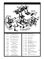
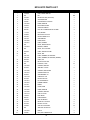
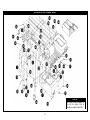
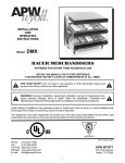
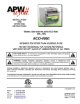
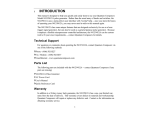
INSTALLATION AND OPERATING INSTRUCTIONS
ELECTRIC FRYERS
Models: EF-15iN, EF-30iNT, EF-30iNTC
INTENDED FOR OTHER THAN HOUSEHOLD USE
RETAIN THIS MANUAL FOR FUTURE REFERENCE
OVEN MUST BE KEPT CLEAR OF COMBUSTIBLES AT ALL TIMES
FOR YOUR SAFETY
Do not store or use gasoline or other flammable vapors and liquids in the vicinity of
this or any other appliance
WARNING
Improper installation, adjustment, alteration, service or maintenance can cause
property damage, injury or death. Read the Installation, Operating and Maintenance
Instructions thoroughly before installing or servicing this equipment
WARNING
Initial heating of oven may generate smoke or fumes and must be done in a
well-ventilated area. Overexposure to smoke or fumes may cause nausea or
dizziness.
This equipment has been engineered to provide you with year-round dependable service when used
according to the instructions in this manual and standard commercial kitchen practices.
P/N 882210
APW WYOTT Foodservice Equipment Company
(307) 634-5801 Phone
(307) 637-8071 Fax
P.O. Box 1829
Cheyenne, WY 82003
(800) 752-0863 Toll Free
www.apwwyott.com
1
APW Wyott takes pride in the design and quality of our products. When used as intended and with proper
care and maintenance, you will experience years of reliable operation from this equipment. To ensure best
results, it is important that you read and follow the instructions in this manual carefully.
Installation and start-up should be performed by a qualified installer who thoroughly read, understands and
follows these instructions.
If you have questions concerning the installation, operation, maintenance or service of this product, write
Technical Service Department: APW Wyott Foodservice Equipment Company, P.O. Box 1829, Cheyenne,
WY82003.
SAFETY PRECAUTIONS
Before installing and operating this equipment be sure everyone involved in its operation are fully trained
and are aware of all precautions. Accidents and problems can result by a failure to follow fundamental rules
and precautions.
The following words and symbols, found in this manual, alert you to hazards to the operator, service
personnel or the equipment. The words are defined as follows:
DANGER: This symbol warns of imminent hazard which will result in serious injury or
death.
WARNING: This symbol refers to a potential hazard or unsafe practice, which could
result in serious injury or death.
CAUTION: This symbol refers to a potential hazard or unsafe practice, which may
result in minor or moderate injury or product or property damage.
NOTICE: This symbol refers to information that needs special attention or must be
fully understood even though not dangerous.
GENERAL INFORMATION
THIS MANUAL SHOULD BE RETAINED FOR FUTURE REFERENCE
CAUTION: These models are designed, built, and sold for commercial use. If these
models are positioned so the general public can use the equipment make sure that
cautions, warnings, and operating instructions are clearly posted near each unit so
that anyone using the equipment will use it correctly and not injure themselves or
harm the equipment.
WARNING: Check the data plate on this unit before installation. Connect the unit only
to the voltage and frequency listed on the data plate. Connect only to 1 or 3 phase as
listed on the data plate.
WARNING: Electrical and grounding connections must comply with the applicable
portions of the national electrical code and/or other local electrical codes.
WARNING: Disconnect device from electrical power supply and place a Tag
Out-Lockout on the power plug, indicating that you are working on the circuit.
2
WARNING: Install per the spacing requirements listed in the installation section of this
manual. We strongly recommend having a competent professional install the
equipment. A licensed electrician should make the electrical connections and connect
power to the unit. Local codes should always be used when connecting these units to
electrical power. In the absence of local codes, use the latest version of the National
Electrical Code.
WARNING: This device should be safely and adequately grounded in accordance
with local codes, or in the absence of local codes, with the National Electrical code,
ANSI/NFPA 70, Latest Edition to protect the user from electrical shock. It requires a
grounded system and a dedicated circuit, protected by a fuse or circuit breaker of
proper size and rating. Canadian installation must comply with the Canadian Electrical
Code, CSAC22.2, as applicable.
CAUTION: Do not set the fryer with its back flat against the wall. It will not operate
properly unless there is at least 3" breathing space behind fryer.
WARNING: A factory authorized agent should handle all maintenance and repair.
Before doing any maintenance or repair, contact APW Wyott.
WARNING: Never clean any electrical unit by immersing it in water. Turn off before
cleaning surface.
WARNING: An earthing cable must connect the appliance to all other units in the
complete installation and from there to an independent earth connection.
NOTICE: The unit when installed must be electrically grounded and comply with local
codes, or in the absence of local codes, with the national electrical code
ANSI/NFPA70- latest edition. Canadian installation must comply with
CSA-STANDARD C.22.2 Number 0 M1982 General Requirements-Canadian
Electrical Code Part II, 109-M1981- Commercial Cooking Appliances.
WARNING: SHOCK HAZARD - De-energize all power to equipment before cleaning
the equipment.
NOTICE: This product is intended for commercial use only. Not for household use.
NOTICE: Local codes regarding installation vary greatly from one area to another.
The National Fire Protection Association, Inc. states in its NFPA96 latest edition that
local codes are “Authority Having Jurisdiction” when it comes to requirement for
installation of equipment. Therefore, installation should comply with all local codes.
CAUTION: This product when stacked has more than one power supply connection
point. Disconnect all power supplies before servicing.
CAUTION: Suitable for installation on combustible floor when installed with legs or
casters provided.
3
WARNING: SHOCK HAZARD - Do not open any panels that require the use of tools.
IMPORTANT FOR FUTURE REFERENCE
Please complete this information and retain this manual for the life of the equipment. For Warranty
Service and/or Parts, this information is required.
Model Number
Serial Number
Date Purchased
IMMEDIATELY INSPECT FOR SHIPPING DAMAGE
All containers should be examined for damage before and during unloading. The freight carrier has
assumed responsibility for its safe transit and delivery. If equipment is received damaged, either apparent
or concealed, a claim must be made with the delivering carrier.
A)
Apparent damage or loss must be noted on the freight bill at the time of delivery. It must then be
signed by the carrier representative (Driver). If this is not done, the carrier may refuse the claim. The
carrier can supply the necessary forms.
B)
Concealed damage or loss if not apparent until after equipment is uncrated, a request for inspection
must be made to the carrier within 15 days. The carrier should arrange an inspection. Be certain to
hold all contents and packaging material.
Installation and start-up should be performed by a qualified installer who thoroughly read, understands and
follows these instructions.
TABLE OF CONTENTS
SECTION
ITEM
PAGE
1
2
3
4
5
6
7
8
9
10
11
12
General Information
Description
Installation
Thermostat Calibration
Operation
Maintenance
Cleaning
Wiring Diagrams
Troubleshooting Guide
Suggested Temperature & Times
Replacement Parts
Warranty
4
4
5
5
6
6
7
8
9
11
12
12
17
1. GENERAL INFORMATION
General Installation:
1.
2.
3.
4.
Always clean equipment thoroughly before first use (see “General Cleaning Instructions”).
Check rating label for your model designation & electrical rating.
For best results, use stainless steel countertops.
Attach legs to unit.
General Operation Instructions:
1.
2.
3.
4.
All food service equipment should be operated by trained personnel.
Do not allow your customers to come in contact with any surface labeled “CAUTION HOT”.
Where applicable, never pour cold water into dry heated units.
NEVER hold food below 140°F.
General Cleaning Instructions:
1. Refer to section 7, page 7.
General Troubleshooting:
Always ask and check:
1.
2.
3.
4.
Is the unit connected to a live power source?
Check circuit breaker.
Is power switch “ON” and pilot light glowing?
Check rating label. Are you operating unit on proper voltage?
If the above checks out and you still have problems, call an APW/Wyott authorized service agency.
2. DESCRIPTION
Electric Fryers:
These electric units are designed for countertop operation. They are used for producing evenly cooked,
perfectly fried products.
3. INSTALLATION
1. Follow General Installation Instructions on previous page.
Screw legs into the permanently fastened nuts on the four corners of the unit and tighten by hand. Level the
fryer by turning the adjustment screw at the bottom of each leg. Do not slide unit with legs mounted, lift if
necessary to move unit.
For testing, see the wiring diagrams in this manual for the rated amperages.
NOTE: These values are nominal ratings. Field wire connections must be capable of withstanding
anticipated surges.
CAUTION: Installing personnel should be guided by National Electrical Code NFPA
Number 70- (Latest Edition), and applicable local codes.
5
4. THERMOSTAT CALIBRATION
Checking Thermostat Calibration:
The fryer thermostat is carefully calibrated at the factory so that dial settings match actual frying compound
temperatures. Field re-calibration is seldom necessary unless the unit has been mishandled in transit or
abused. Re-calibration should not be resorted to unless considerable experience with cooking results
definitely proves that the control is not maintaining the temperature to which the dial is set.
1.
2.
3.
4.
5.
6.
7.
8.
9.
To check compound frying temperatures when re-calibrating, use a precision test instrument, or a good
grade mercury thermometer. Fill the tank half way between the MAX and MIN marks on the tank.
Frying compound temperature should be checked at the center of the tank, approximately 1” to 1 1/2”
below surface of frying compound.
Turn the dial of the thermostat being checked to the 350°Fmark.
Allow temperature to stabilize, or until the thermostat cycles to “OFF” three times after starting with
cold frying compound. With power “ON”, read highest and lowest frying compound temperature, as
thermostat cycles through at least twice, average the reading.
Thermostat should be re-calibrated if temperature reading is not within 10 degrees of the control knob
setting (350°F +/- 15°F). If re-calibration is required, continue with steps 6, 7, 8 and 9.
Remove control knob by grasping outer edge and pulling straight out, without twisting or turning.
Hold thermostat dial shaft “B” (Figure 1) stationary with pliers, and with a screwdriver, turn screw “A”
clockwise to obtain a lower temperature; or counter-clockwise for higher temperature. Each ¼ turn
(90° rotation) of screw “A” represents 18°F.
Replace thermostat control knob.
Recheck thermostat as in Steps 4 and 5 above. If the fat temperature is not within 20 degrees of dial
setting (350°F +/- 20°F), it means that the sensing element is inoperative and the thermostatic control
should be replaced.
FIGURE 1
5. OPERATING
Removing Fry Tanks:
1.
2.
3.
4.
Remove fry baskets.
Carefully grasp the element handle. CAUTION: May be hot. Pull out the head lock on the left of the
head.
Lift the element handle while at the same time, pulling the head lock. This will permit lifting the
elements to just above frying compound level in tank. The element can be left in this position for
draining frying compound.
Again, lift the element handle while pulling the head lock, until the elements lock themselves at a
higher position.
6
5.
Firmly grasp both handles of fry tank and lift it out. After replacing the fry tank, simply pull the head
lock; and at the same time, pull down the element handle until the elements rest on fry tank bottom.
6.
Both the lifting out and lowering of elements can be done in one swing, without stopping at the
intermediate position.
6. MAINTENANCE
1.
Fill the fry tank half way between the MAX and MIN marks on the tank with approximately 15 lbs. of
liquid or melted frying compound. Do not fill past the MAX.
NOTE: This fryer is not equipped with a melt cycle option. Air holes caused when packing solid
frying compound into the fryer can cause hot spots on the heating element sheath, resulting in
momentary overheating of some of the frying compound and premature frying compound
breakdown. It can also damage the heating elements. If it is necessary to use solid frying
compound, it must be melted before adding to fry tank.
Turn the thermostat to the desired frying temperature. The yellow “HEAT ON” light will stay on
until the temperature set on the thermostat is reached, then the light cycles off. The fryer is now
ready to begin frying. After a load has been fried, do not lower the next load into the frying
compound until the “HEATON” light cycles off.
2. Do not let the frying compound level drop below the MIN mark on the tank. For proper operation of the
fryer and good frying results, the frying compound level should be maintained.
3. Use a quality frying compound.
4. Filter the frying compound frequently, at least once a day.
5. Skim out food particles frequently with the strainer/skimmer.
6. Add at least 15% (of fry tank capacity) of fresh frying compound daily, (more if possible) without
overloading the tank. If 15% of the frying compound is not used during frying, remove some of the
frying compound for other use (gravy, griddle frying, etc.) to permit adding fresh frying compound.
7. Do not overload the fry baskets. Approximately half-full or even less is correct. If foods are taking
longer to fry than the chart shows, or are not browning, over-loading is a probable cause.
8. Prepare the food properly.
9. Keep salt out of the frying compound. Do not salt food with the basket above the kettle.
10. Assure a good thermostat operation.
11. Keep the fry tank and elements clean.
7
7. CLEANING
1. The frequency of cleaning should depend on the load conditions. Set a definite cleaning schedule
corresponding to how hard the kettle is used. Cleaning should be done at least once a week.
A.
B.
C.
D.
E.
F.
G.
H.
I.
J.
K.
L.
M.
N.
O.
P.
Q.
Turn the thermostat to “OFF” and allow unit to cool down.
Lift the elements to drain position. Wire brush or scrape elements to remove any solids adhering
to the elements.
Raise the elements. Lift out fry tank. Strain the frying compound into a clean container.
Replace empty fry tank, lower elements to rest inside the tank.
Add water to the "MAX" mark on tank.
Add any good grade of cleaner, following cleaning instructions.
Turn the thermostat to 250°F and let the heating unit bring the solution to a boil.
Boil long enough to loosen or dissolve all varnish or carbon deposits, approximately 30 minutes.
Turn the unit off and lift out the elements to drain position.
If necessary, clean the thermostat bulbs using a long-handled fiber or plastic brush and mild soap
solution.
Rinse with clean water to remove all cleaning mixture.
Lift out the fry tank and drain. Repeat steps J & K with fry tank.
Rinse the inside of the tank with 2 cups of vinegar.
Rinse with clean water until the vinegar odor is gone. The fry tank must be thoroughly rinsed,
since even a trace of cleaner left inside the tank will ruin frying compound.
Dry thoroughly. Replace the tank and lower the elements.
Shut the unit off and cover tank until ready for further use.
Thin films of oil subjected to frying temperatures quickly form into a gummy consistency. In order
to avoid these gum formations, keep all other surfaces of the unit clean by polishing stainless
steel surfaces with a damp cloth. To remove discolorations or oil film, a nonabrasive cleaner may
be used.
8
8. WIRING DIAGRAMS
CHECK DATA PLATE & CONNECT TO 208 OR 240V AS INDICATED
CHECK DATA PLATE & CONNECT TO 208 OR 240V AS INDICATED
MODEL #
EF15-iN
EF30-iNT
EF15-iN208
VOLTS
240
WATTS
5700
AMPS
23.8
WIRE
12
VOLTS
208
WATTS
4280
AMPS
20.6
WIRE
12
-
-
-
-
208
5700
27.5
10
MODEL #
VOLTS
WATTS
AMPS
WIRE
VOLTS
WATTS
AMPS
WIRE
240
11400
47.6
6
208
8560
41.2
6
Wire sizes listed above are for reference only. Check local
Codes or the National Electrical Code for sizes to be used.
Wire sizes listed above are for reference only. Check local
Codes or the National Electrical Code for sizes to be used.
THIS UNIT TO BE CONNECTED TO 1Ø ONLY
THIS UNIT TO BE CONNECTED TO 1Ø ONLY
9
CHECK DATA PLATE & CONNECT TO 208 OR 240V AS INDICATED
MODEL #
EF30-iNT
VOLTS
WATTS
AMPS
240
11400
23.8 & 23.8
WIRE VOLTS WATTS
12
208
8560
AMPS
WIRE
20.6 & 20.6
12
CHECK DATA PLATE & CONNECT TO 208 OR 240V AS INDICATED
MODEL #
EF30-iNTC-208
VOLTS
208
WATTS
11400
AMPS
55.0
WIRE
4
Wire sizes listed above are for reference only. Check local
Codes or the National Electrical Code for sizes to be used.
Wire sizes listed above are for reference only. Check local
Codes or the National Electrical Code for sizes to be used.
THIS APPLIANCE HAS MORE THAN ONE POWER
SUPPLY CONNECTION POINT. DISCONNECT ALL
POWER SUPPLIES BEFORE SERVICING
THIS UNIT TO BE CONNECTED TO 1Ø ONLY
THIS UNIT TO BE CONNECTED TO 1Ø ONLY
10
Problem
Excessive and premature
foaming.
Greasy food/excessive
frying compound
absorption.
“Objectionable” odor or
flavor of frying compound.
“Objectionable” flavor of
fried food.
Excessive smoking of
frying compound.
Excessive darkening of
frying compound.
Frying compound won’t
hold heat.
Food crust color not
brown.
X
Rapid breakdown of frying
compound.
X
X X
X X
X X X
X
X
X
X
X
X
X
11
X
X
X X
X
X
X
X X
X X X
X X X
X
X
X X
X
X
X
X
X X
X X
X
X
X
X
X
X
X
X
X
X
X
X
X
X
X
X
X
Inadequate cleaning of fry tank.
Keeping food in frying compound
after cooking.
Inadequate filtering of frying
compound. Excessive crumbs in
fry tank.
Cooking time too short.
Poor quality of frying compound
(Either initially or after excessive
use)
Drip-back from exhaust stack.
Food being fried may be of poor
quality.
Frying in foam.
Contamination of frying
compound. (Due to salt or other
foreign material)
Improper preparation of food.
Inadequate frying compound
turnover.
High moisture content in food
being fried.
Improper draining of food after
frying.
Overloading the fry tank.
Frying temperature too low.
(Check thermostat)
Frying temperature too high/
overheating. (Check thermostat)
9. TROUBLESHOOTING GUIDE
Possible Cause
X
X
X
X
X
X
X
10. SUGGESTED TEMPERATURES & TIMES
CONTROL
TIME
SETTING
IN
(FAHRENHEIT) MINUTES
FOOD
DOUGHNUTS
FOOD
CONTROL
SETTING
(FAHRENHEIT)
TIME
IN
MINUTES
SEAFOOD
Cake Type
375°
1½-2
Fish Cakes
Yeast Raised
375°
2-2½
Clams
350°
2-3
Fillets (Small)
350°
1-3
MEAT
Cutlets (Less than 1/2” thick)
350°
5-8
Oysters
350°
3-5
Chicken Fried Steak
350°
5-8
Scallops
350°
2-5
Chops (Very lean)
350°
5-8
Shrimp
350°
3-5
Smelts
350°
4-6
Chinese Noodles
375°
1-2
VEGETABLES
Croquettes
350°
2-3
Egg Plant
350°
5-7
French Toast
350°
2-3
Onion Rings
350°
3-5
Glazed Cinnamon Apples
300°
5 - 10
Potatoes
French Fried Sandwiches
350°
1-2
(1/2" Strips, one-operation)
350°
6-9
Potatoes (Blanch)
350°
4-6
MISCELLANEOUS
POULTRY
Chicken (Large pieces)
325°
10 - 5
Potatoes (Brown)
350°
2-3
Chicken (Small pieces)
350°
7 - 10
Potatoes (Julienne)
350°
3-5
Chicken (Pre-cooked)
325° - 350°
3-5
Turkey (Small pieces)
325°
9 - 10
11. REPLACEMENT PARTS
CONTROL HEAD (MODELS: EF-15IN & EF-30INT)
Item
1
2
3
4
5
6
7
8
P/N
21818140
1439729
13801-00
81300-00
1515300
14876-00
8705504
2125502
Description
Control Head, Elec. Fryer W/a
Heating Unit Assembly
Switch, Hi-limit
8-32 X 3/8 Type T
Ind Light,rect,amb,250v,2/tabs
Thermostat
Knob, Thermostat
Grommet Split
Quan Item
P/N
Description
1
9 64285901 Clamp Bulb
1
10 8944100 Clip Lead
1
11 8837018 Label Reset
2
12 8108300 Screw, Pan Head 6-32 X 1/2
1
13 8500600 Washer, Lock #6 S/s
1
14 8402900 Nut, Hex, 6-32 Ss
1
15 8103400 Screw, Mach, 6-32 X 1/4" Lg.
2
12
Quan
4
4
1
4
4
4
2
EF-15IN
18
7
4
3
5
2
16
23
24
11
17
21
20
26
8
22 28
9
13
14
19
6 15
1
12
10
27
25
29
Item
P/N
Description
Quan Item
P/N
Description
FRY BASKET
DOOR ELECTRIC FRYER
BUSHING, SNAP HEYCO .5" I.D.
LUG, SOLDERLESS
LABEL, GROUND MARKER
LABEL, DIAGRAM
DECAL UL & CSA COOK
BAFFLE, INTERIOR EF-15iN
SCREW, TAPPING, 10-32 X 3/8, TYPE
AB, S/S
MS RD HD PH 10-24 X 1/2 SS
#10-24 HX NUT GRN
LOGO, APWWYOTT CASTED
INSERT, 3/4-10 THREAD, PRESS-IN
LEG, HEAVY DUTY 2" DIA. W/ FOOT
FLANGE
1
2
3
4
5
6
7
8
22091162
21810065
21810075
21810085
21810140
22091161
21810096
21810010
BODY FRYER EF-15i
SUPPORT, HEAD WELD ASSEMBLY LS
HEAD SUPPORT OUTSIDE WELD ASSY
HEAD SUPPORT INSIDE
CONTROL AY. 240/208
BACK & BOTTOM 15 LB. FRYER
COVER HEAD
FAT CONTAINER AY
1
1
1
1
1
1
1
1
16
17
18
19
20
21
22
23
3101230f
21810040
8967000
1114100
8837001
21810018
8822310
21810038
9
10
11
12
13
21810023
21810022
8141400
8410400
8415500
BRACKET HANDLE
ELEMENT HANDLE
8-32 x 1/2 MS
NUT,HEX, 8-32 S/S
WING NUT 10-32 S/S
1
1
2
2
4
24
25
26
27
28
8196400
8158800
8422400
2065847
8430500
14
15
8353000
5161000
POP RIVET
CONNECTOR CABLE ROMEX
19
1
29
8633700
13
Quan
2
1
1
1
1
1
1
1
11
1
1
1
4
4
EF-30INT
7
8
14
4
5
6
24 21
3
22
23
11 9 30
25
33
26
31
20
2
16
17
18 15
29
10
19
34
Item
Description
Quan
27
Item
P/N
1
22092313
BODY, TWIN ELEC. FRYER W/A i-LINE
1
19
8415500
WING NUT 10-32 S/S
6
2
22092316
BACK, BOTTOM EF-30iNT
1
20
8837001
LABEL, GROUND MARKER
1
21810065
SUPPORT, HEAD WELD ASSEMBLY
LS
1
21
21810023
BRACKET HANDLE
2
4
21810265
SUPPORT, HEAD WELD ASSEMBLY
RS
1
22
21810022
ELEMENT HANDLE
2
5
21810275
HEAD SUPPOR, OUTSIDE ASSY.
1
23
8141400
8-32 x 1/2 MS
4
6
21810285
HEAD SUPPORT, INSIDE ASSY.
1
24
8410400
4
7
21810140
CONTROL AY. 240/208
2
25
21810218
NUT,HEX, 8-32 S/S
LABEL, DIAGRAM EL. TWIN FRYER
208/240V UNITS
8
21810096
COVER HEAD
2
26
8822310
DECAL UL & CSA COOK
1
9
8170700
SCREW, 10-32x1/2, TYPE AB
19
27
43813103
LABEL, WRNG, HOT SURFC
1
10
21810010
FAT CONTAINER AY
2
28
43813149
LABEL, WRN HOT SURF (FRNCH)
1
3
P/N
1 35 28 13
Description
Quan
1
11
21810040
DOOR ELECTRIC FRYER
1
29
3101232
BASKET, FULL SIZE, 30iH
2
12*
8832600
LABEL, SERVICE HOTLINE
1
30
21810238
BAFFLE, INTERIOR EF-30iNT
1
13
8825300
DECAL, LEG
1
31
8353000
POP RIVET
14
8967000
BUSHING, SNAP HEYCO .5" I.D.
1
32*
1044700
RTV SEALANT, SILVER
15
8158800
MS RD HD PH 10-24 X 1/2
1
33
8430500
4
16
1114100
LUG, SOLDERLESS
1
34
8633700
INSERT, 3/4-10 THREAD, PRESS-IN
LEG, HEAVY DUTY 2" DIA. W/ FOOT
FLANGE
17
8422400
#10-24 HX NUT GRN
1
35
2065847
LOGO, APWWYOTT CASTED
1
18
5161000
CONNECTOR CABLE ROMEX
1
14
30
0.00 OZ
4
EF30-INTC PARTS LIST
Item
P/N
Description
Quan
1
22092314
BODY, FRYER TWIN W/A
2
N/A
N/A
1
3*
81034-00
MS PN6-32X1/4SS (* Not Shown)
4
4
13017-00
SWITCH,ROCKER
2
5
2065847
LOGO APWWYOTT CASTED
1
6
218100-50
PANEL, INTERIOR
1
7
22092317
BACK & BOTTOM W/A
1
8
13021-00
SOLID STATE RELAY
2
N/A
9
8633700
LEG, HD 2” DIAMETER W/FOOT FLANGE
4
10
11141-00
LUG, GROUND
1
11
81588-00
MS RD PH10-24X1/2 SS
1
12
84224-00
HEX NUT GREEN 10-24
1
13
51610-00
STRAIN RELIEF
1
14
218100-40
DOOR, FRYER
1
15
218102-21
LABEL, DIAGRAM
1
16
N/A
DECAL, SPECIFICATION
1
17
218100-23
BRACKET, HANDLE
2
18
N/A
DECAL, UL & CSA COOK
1
19
88326-00
LABEL, SERVICE HOTLINE
1
20
N/A
DECAL, NSF
1
21
43813103
LABEL, WARNING, HOT SURFACE
1
43813149
LABEL, WARNING, HOT SURFACE (FRENCH)
1
22
88253-00
LABEL, LEG
1
23
81414-00
MS TR PH 8-32X1/2SS
4
24
N/A
POP RIVET, 1/8 SS
22
25
218100-65
SUPPORT, HEAD W/A
1
26
84155-00
WING NUT 10-32 S/S
6
27
218102-85
SUPPORT, HEAD INS.W/A
1
28
218102-75
SUPPORT HEAD OUT.
1
29
89785-00
SNAP BUSHING 1.00
1
30
218101-09
CONTROLAY .208
1
31
84104-00
HEX NUT #8-32 SS
6
32
218100-10
FAT CONTAINER AY.
2
33
218100-22
ELEMENT HANDLE
2
34
31012-32
BASKET
2
35
218100-96
COVER, HEAD
2
36
218102-50
PANEL, INTERIOR
1
37
218102-65
SUPPORT, HEAD W/A
1
38
218101-18
CONT AY.208 RT
1
39
15030-05
FUSE BLOCK
2
40
88370-01
LABEL GROUND
1
41
15030-06
FUSE 40 AMP 250V
4
42
81721-00
MS PN PH 10-32X1/2SS
8
43
84176-00
HEX NUT 10-32 SS
8
44
81964-00
SCR TAP #10-32X3/8SS
25
45
N/A
SEALASTIC AL DOW 732
1
46
218102-26
BAFFLE
2
47*
8136000
NUT, SELF CLINCHING 8-32
4
15
EF30-INTC EXPLODED VIEW
NOTE:
Fuse block shown mounted on
item #6 for clarity. Part is
actually mounted on item #36.
16
APW WYOTT EQUIPMENT LIMITED WARRANTY
APW Wyott Foodservice Equipment Company warrants it's equipment against defects in materials and workmanship, subject to the
following conditions:
This warranty applies to the original owner only and is not assignable.
Should product fail to function in its intended manner under normal use within the limits defined in this warranty, at the option of
APW Wyott such product will be repaired or replaced by APW Wyott or its Authorized Service Agency. APW Wyott will only be
responsible for charges incurred or service performed by its Authorized Service Agencies. The use of other than APW Wyott Authorized
Service Agencies will void this warranty and APW Wyott will not be responsible for such work or any charges associated with same. The
closest APW Wyott Authorized Service Agent must be used.
This warranty covers products shipped into the 48 contiguous United States, Hawaii, metropolitan areas of Alaska and Canada. There will
be no labor coverage for equipment located on any island not connected by roadway to the mainland.
Warranty coverage on products used outside the 48 contiguous United States, Hawaii, and metropolitan areas of Alaska and Canada may
vary. Contact the international APW Wyott distributor, dealer, or service agency for details.
Time Period
One year parts, one year labor, effective from the date of purchase by the original owner. The Authorized Service Agency may, at their
option, require proof of purchase. Parts replaced under this warranty are warranted for the un-expired portion of the original product
warranty only.
Exceptions
* Gas/Electric Cookline: Models GCB, GCRB, GF, GGM, GGT, CHP-H, EF, EG, EHP. Three (3) Year Warranty on all
component parts, except switches and thermostats. (2 additional years on parts only. No labor on second or third year.)
*Broiler Briquettes, Rock Grates, Cooking Grates, Burner Shields, Fireboxes: 90 Day Material Only. No Labor.
* Heat Strips Models FD, FDL, FDD, FDDL. Two (2)YearWarranty on element only. No labor second year.
* Glass Windows, Door, Seals, Rubber Seals, Light Bulbs: 90 Day Material Only. No Labor.
In all cases, parts covered by extended warranty will be shipped FOB the factory after the first year.
Portable Carry In Products
Equipment weighing over 70 pounds or permanently installed will be serviced on-site as per the terms of this warranty. Equipment
weighing 70 pounds or under, and which is not permanently installed, i.e. with cord and plug, is considered portable and is subject to the
following warranty handling limitations. If portable equipment fails to operate in its intended manner on the first day of connection, or
use, at APW Wyott's option or its Authorized Service Agency, it will be serviced on site or replaced.
From day two through the conclusion of this warranty period, portable units must be taken to or sent prepaid to the APW Wyott
Authorized Service Agency for in-warranty repairs. No mileage or travel charges are allowed on portable units after the first day of use. If
the customer wants on-site service, they may receive same by paying the travel and mileage charges. Exceptions to this rule: (1)
countertop warmers and cookers, which are covered under the Enhanced Warranty Program, and (2) toasters or rollergrills which have in
store service.
Exclusions
The following conditions are not covered by warranty:
* Equipment failure relating to improper installation, improper utility connection or supply and problems due to ventilation.
* Equipment that has not been properly maintained, calibration of controls, adjustments, damage from improper cleaning and
water damage to controls.
* Equipment that has not been used in an appropriate manner, or has been subject to misuse misapplication, neglect, abuse,
accident, alteration, negligence, damage during transit, delivery or installation, fire, flood, riot or act of god.
* Equipment that has the model number or serial number removed or altered.
If the equipment has been changed, altered, modified or repaired by other than an Authorized Service Agency during or after the warranty
period, then the manufacturer shall not be liable for any damages to any person or to any property, which may result from the use of the
equipment thereafter.
This warranty does not cover services performed at overtime or premium labor rates. Should service be required at times which normally
involve overtime or premium labor rates, the owner shall be charged for the difference between normal service rates and such premium
rates. APW Wyott does not assume any liability for extended delays in replacing or repairing any items beyond its control.
In all cases the use of other than APW Wyott Authorized OEM Replacement Parts will void this warranty.
This equipment is intended for commercial use only. Warranty is void if equipment is installed in other than commercial application.
Water Quality Requirements
Water supply intended for a unit that has in excess of 3.0 grains of hardness per gallon (GPG) must be treated or softened before being
used. Water containing over 3.0 GPG will decrease the efficiency and reduce the operation life of the unit.
Note: Product failure caused by liming or sediment buildup is not covered under warranty.
"THE FOREGOING WARRANTY IS IN LIEU OF ANY AND ALL OTHER WARRANTIES EXPRESSED OR IMPLIED
INCLUDING ANY IMPLIED WARRANTY OR MERCHANTABILITY OR FITNESS FOR PARTICLUAR PURPOSES AND
CONSTITUTES THE ENTIRE LIABILITY OF APW WYOTT. IN NO EVENT DOES THE LIMITED WARRANTY EXTEND
BEYOND THE TERMS HEREIN."
9/05
17