1
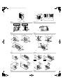
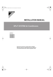
00_CV_3PN07193-6F.fm Page 1 Wednesday, September 2, 2009 4:29 PM INSTALLATION MANUAL System air conditioner Installation manual VRVIII-S System air conditioner RXYMQ36PVJU RXYMQ48PVJU English Manuel d’installation Conditionneur d’air VRVIII-S System Français Manual de instalación Acondicionador de aire con sistema VRVIII-S Español Read these instructions carefully before installation. Keep this manual in a handy place for future reference. This manual should be left with the equipment owner. Lire soigneusement ces instructions avant l’installation. Conserver ce manuel à portée de main pour référence ultérieure. Ce manuel doit être donné au propriétaire de l’équipement. Lea cuidadosamente estas instrucciones antes de instalar. Guarde este manual en un lugar a mano para leer en caso de tener alguna duda. Este manual debe permanecer con el propietario del equipo. 00_CV_3PN07193-6F.fm Page 2 Wednesday, September 2, 2009 4:29 PM 1 2 6 3 7 1 8 5 4 3 2 figure 1 figure 2 1 4 1 2 e 2 5 4 (in.) 2 60 or mor 40 or more 40 or mor e 5 3 e 60 or mor 60 or more 6 3 figure 3 figure 4 [1] [2] [1] [2] or 20 ore m 4o re o rm e or rm ore 4o r 4o rm [3] ore mo e 6 mo or re [3] 20 or more 4o rm 40 or more 6 mo or re rm 4o re 4o 20 or more 40 or more 6 or or m 40 or more 40 mo or re ore re re 8o r 2o rm 8 mo or re (in.) 1 ore (in.) mo figure 5 12 or mo figure 6 [1] [2] [1] [2] H L L re 20 or mo re r 0o or 20 ore m L>H L>H re 4 or 20 ore m [4] or 20 ore m [3] mo H r 4 oore m or 20 ss le 40 or more 40 or more or 20 ss le [4] [3] 40 or more 40 or more L H (in.) figure 7 20 or m ore 40 or ore m (in.) figure 8 40 A or 10 ore m L H or 12 ore m A or mo or 12 ore m 00_CV_3PN07193-6F.fm Page 3 Wednesday, September 2, 2009 4:29 PM [6] [5] [7] [8] or 20 ore m or 20 ore m 40 or more H H L or 20 ore m (in.) H H L L>H 40 or more L r 4 oore m L A A or 40 ore m A or 40 ore m or 60 ore m figure 8 Z [1] [1] or 80 ore m or mo [2] r 4 oore m 6 3 7 r 8 oore m or 40 ore m re 40 1 2 4 [2] Z 4 L A 4 (in.) 12 or H ore m or 60 ore m (in.) figure 9 or 24 ore m 5 r 0o 12 ore m figure 10 figure 14 1 7 2 3 3 2 1 15/16 3 5 5 1 (in.) 6 4 4 5 6 4 6 figure 12 4 8 7 figure 11 6 4 8 8 7 7 figure 15 8 7 1 1 5 1/2 13 3/4 (13 5/8~14) 24 3/8 4 5/8 8 5/8 11 3/8 5 1/2 3 1 3/4 4 3 16 5/8 24 1/8 (in.) 2 4 1 2 6 2 2 5 figure 13 figure 16 figure 17 00_CV_3PN07193-6F.fm Page 4 Wednesday, September 2, 2009 4:29 PM 3 1 4 TO IN/D UNIT TO OUT/D UNIT F1 F2 F1 F2 8 2 F1 F2 2 6 7 1 F1 F2 F1 F2 F1 F2 F1 F2 F1 F2 F1 F2 F1 F2 3 10 11 figure 19 figure 20 2 5 1 L1 L2 9 2 4 11 3 6 5 3 4 A 1 7 2 8 figure 18 B figure 21 1 1 1 2 3 2 4 6 5 4 4 8 7 4 4 figure 23 1 2 1 5 6 figure 22 2 3 3 figure 24 figure 25 6 2 9 1 11 10 8 7 1 2 2 4 3 6 3 4 5 figure 26 figure 27 1 8 7 2 1 2 5 3 figure 29 6 figure 28 8 9 10 3 4 5 4 figure 30 7 6 5 01_EN_3PN07193-6F.fm Page 1 Tuesday, September 1, 2009 4:13 PM RXYMQ36PVJU RXYMQ48PVJU VRVIII-S System air conditioner CONTENTS 1. SAFETY CONSIDERATIONS.................................................. 1 2. INTRODUCTION...................................................................... 2 2-1. Combination ...................................................................... 3 2-2. Standard operation limit .................................................... 3 2-3. Spec list ............................................................................ 3 2-4. Electrical properties .......................................................... 3 2-5. Standard supplied accessories ......................................... 3 2-6. Option accessory .............................................................. 3 3. BEFORE INSTALLATION........................................................ 3 4. SELECTING INSTALLATION SITE ......................................... 4 5. PRECAUTIONS ON INSTALLATION ...................................... 5 6. FIELD WIRING......................................................................... 6 6-1. Wiring connection example for whole system ................... 6 6-2. How to lay the power supply wiring and transmission wiring............................................................ 6 6-3. How to connect the power supply wiring........................... 7 6-4. Transmission wiring connection procedure....................... 7 7. PRECAUTIONS ON REFRIGERANT PIPING......................... 7 7-1. Installation tools ................................................................ 7 7-2. Selecting piping material ................................................... 8 7-3. Protection against contamination when installing pipes ........ 8 7-4. Pipe connection ................................................................ 8 7-5. Connecting the refrigerant piping ...................................... 8 7-6. Heat insulation of piping.................................................... 9 7-7. Example of connection.................................................... 10 7-8. Air tight test and vacuum drying...................................... 11 8. ADDITIONAL REFRIGERANT CHARGE .............................. 12 8-1. Before adding refrigerant ................................................ 12 8-2. Checking the refrigerant tank .......................................... 12 8-3. Adding refrigerant ........................................................... 12 9. POST-WORK CHECKS ......................................................... 12 10. TEST RUN ............................................................................. 12 10-1.Power On–Check Operation .......................................... 12 10-2.Temperature control operation checklist........................ 13 11. CAUTION FOR REFRIGERANT LEAKS ............................... 14 1. SAFETY CONSIDERATIONS Read these “SAFETY CONSIDERATIONS for Installation” carefully before installing air conditioning equipment. After completing the installation, make sure that the unit operates properly during the startup operation. Instruct the customer on how to operate and maintain the unit. Inform customers that they should store this Installation Manual with the Operation Manual for future reference. Always use a licensed installer or contractor to install this product. Improper installation can result in water or refrigerant leakage, electrical shock, fire, or explosion. Meanings of DANGER, WARNING, CAUTION, and NOTE Symbols: DANGER.......Indicates an imminently hazardous situation which, if not avoided, will result in death or serious injury. WARNING.....Indicates a potentially hazardous situation which, if not avoided, could result in death or serious injury. CAUTION ......Indicates a potentially hazardous situation which, if not avoided, may result in minor or moderate injury. It may also be used to alert against unsafe practices. 1 Installation manual NOTE.............Indicates situations that may result in equipment or property-damage accidents only. DANGER • Refrigerant gas is heavier than air and replaces oxygen. A massive leak can lead to oxygen depletion, especially in basements, and an asphyxiation hazard could occur leading to serious injury or death. • Do not ground units to water pipes, gas pipes, telephone wires, or lightning rods as incomplete grounding can cause a severe shock hazard resulting in severe injury or death. Additionally, grounding to gas pipes could cause a gas leak and potential explosion causing severe injury or death. • If refrigerant gas leaks during installation, ventilate the area immediately. Refrigerant gas may produce toxic gas if it comes in contact with fire. Exposure to this gas could cause severe injury or death. • After completing the installation work, check that the refrigerant gas does not leak throughout the system. • Do not install unit in an area where flammable materials are present due to risk of explosions that can cause serious injury or death. • Safely dispose all packing and transportation materials in accordance with federal/state/local laws or ordinances. Packing materials such as nails and other metal or wood parts, including plastic packing materials used for transportation may cause injuries or death by suffocation. WARNING • Only qualified personnel must carry out the installation work. Installation must be done in accordance with this installation manual. Improper installation may result in water leakage, electric shock, or fire. • When installing the unit in a small room, take measures to keep the refrigerant concentration from exceeding allowable safety limits. Excessive refrigerant leaks, in the event of an accident in a closed ambient space, can lead to oxygen deficiency. • Use only specified accessories and parts for installation work. Failure to use specified parts may result in water leakage, electric shocks, fire, or the unit falling. • Install the air conditioner on a foundation strong enough that it can withstand the weight of the unit. A foundation of insufficient strength may result in the unit falling and causing injuries. • Take into account strong winds, typhoons, or earthquakes when installing. Improper installation may result in the unit falling and causing accidents. • Make sure that a separate power supply circuit is provided for this unit and that all electrical work is carried out by qualified personnel according to local state, and national regulations. An insufficient power supply capacity or improper electrical construction may lead to electric shocks or fire. • Make sure that all wiring is secured, that specified wires are used, and that no external forces act on the terminal connections or wires. Improper connections or installation may result in fire. • When wiring, position the wires so that the terminal box lid can be securely fastened. Improper positioning of the terminal box lid may result in electric shocks, fire, or the terminals overheating. • Before touching electrical parts, turn off the unit. • Be sure to install a ground fault circuit interrupter if one is not already available. This helps prevent electrical shocks or fire. English 01_EN_3PN07193-6F.fm Page 2 Tuesday, September 1, 2009 4:13 PM • Securely fasten the outside unit terminal cover (panel). If the terminal cover/panel is not installed properly, dust or water may enter the outside unit causing fire or electric shock. • When installing or relocating the system, keep the refrigerant circuit free from substances other than the specified refrigerant (R-410A) such as air. Any presence of air or other foreign substance in the refrigerant circuit can cause an abnormal pressure rise or rupture, resulting in injury. • Do not change the setting of the protection devices. If the pressure switch, thermal switch, or other protection device is shorted and operated forcibly, or parts other than those specified by Daikin are used, fire or explosion may occur. CAUTION • Do not touch the switch with wet fingers. Touching a switch with wet fingers can cause electric shock. • Do not allow children to play on or around the unit to prevent injury. • Do not touch the refrigerant pipes during and immediately after operation as the refrigerant pipes may be hot or cold, depending on the condition of the refrigerant flowing through the refrigerant piping, compressor, and other refrigerant cycle parts. Your hands may suffer burns or frostbite if you touch the refrigerant pipes. To avoid injury, give the pipes time to return to normal temperature or, if you must touch them, be sure to wear proper gloves. • Heat exchanger fins are sharp enough to cut. To avoid injury wear glove or cover the fins when working around them. • Install drain piping to proper drainage. Improper drain piping may result in water leakage and property damage. • Insulate piping to prevent condensation. • Be careful when transporting the product. • Do not turn off the power immediately after stopping operation. Always wait for at least 5 minutes before turning off the power. Otherwise, water leakage may occur. • Do not use a charging cylinder. Using a charging cylinder may cause the refrigerant to deteriorate. • Refrigerant R-410A in the system must be kept clean, dry, and tight. (a) Clean and Dry -- Foreign materials (including mineral oils such as SUNISO oil or moisture) should be prevented from getting into the system. (b) Tight -- R-410A does not contain any chlorine, does not destroy the ozone layer, and does not reduce the earth’s protection again harmful ultraviolet radiation. R-410A can contribute to the greenhouse effect if it is released. Therefore take proper measures to check for the tightness of the refrigerant piping installation. Read the chapter Refrigerant Piping and follow the procedures. • Since R-410A is a blend, the required additional refrigerant must be charged in its liquid state. If the refrigerant is charged in a state of gas, its composition can change and the system will not work properly. • The indoor unit is for R-410A. See the catalog for indoor models that can be connected. Normal operation is not possible when connected to other units. • Remote controller (wireless kit) transmitting distance can be shorter than expected in rooms with electronic fluorescent lamps (inverter or rapid start types). Install the indoor unit far away from fluorescent lamps as much as possible. • Indoor units are for indoor installation only. Outdoor units can be installed either outdoors or indoors. English • Do not install the air conditioner in the following locations: (a) Where a mineral oil mist or oil spray or vapor is produced, for example, in a kitchen. Plastic parts may deteriorate and fall off or result in water leakage. (b) Where corrosive gas, such as sulfurous acid gas, is produced. Corroding copper pipes or soldered parts may result in refrigerant leakage. (c) Near machinery emitting electromagnetic waves. Electromagnetic waves may disturb the operation of the control system and cause the unit to malfunction. (d) Where flammable gas may leak, where there is carbon fiber, or ignitable dust suspension in the air, or where volatile flammables such as thinner or gasoline are handled. Operating the unit in such conditions can cause a fire. • Take adequate measures to prevent the outside unit from being used as a shelter by small animals. Small animals making contact with electrical parts can cause malfunctions, smoke, or fire. Instruct the customer to keep the area around the unit clean. NOTE • Install the power supply and control wires for the indoor and outdoor units at least 3.5 feet away from televisions or radios to prevent image interference or noise. Depending on the radio waves, a distance of 3.5 feet may not be sufficient to eliminate the noise. • Dismantling the unit, treatment of the refrigerant, oil and additional parts must be done in accordance with the relevant local, state, and national regulations. • Do not use the following tools that are used with conventional refrigerants: gauge manifold, charge hose, gas leak detector, reverse flow check valve, refrigerant charge base, vacuum gauge, or refrigerant recovery equipment. • If the conventional refrigerant and refrigerator oil are mixed in R-410A, the refrigerant may deteriorate. • This air conditioner is an appliance that should not be accessible to the general public. • The wall thickness of field-installed pipes should be selected in accordance with the relevant local, state, and national regulations. 2. 1. 2. 3. 4. 5. INTRODUCTION This series uses R410A new refrigerant. Be absolutely sure to comply with “7. PRECAUTIONS ON REFRIGERANT PIPING”, because even greater caution is needed to prevent impurities from entering R410A (mineral oils and water). The design pressure is 478PSI (3.3MPa), which means that piping may be thicker than conventionally, so please refer to “7. PRECAUTIONS ON REFRIGERANT PIPING”. This is a mixed refrigerant, so charge as a liquid when adding refrigerant. (If charged as a gas, the composition of the refrigerant may change, preventing normal operation.) The indoor unit must use R410A. See the catalog for indoor unit models which can be connected. (Normal operation is not possible when connected to other units.) The power supply of this series is single-phase, 208/230V, 60Hz. 2 01_EN_3PN07193-6F.fm Page 3 Tuesday, September 1, 2009 4:13 PM 2-1 Combination 2-4 Electrical properties The indoor units can be installed in the following range. • Be sure to connect a dedicated indoor unit. See the catalog for indoor unit models which can be connected. • Total capacity/quantity of indoor units 〈Outdoor unit〉 〈Total capacity of indoor units〉 〈Total quantity of indoor units〉 RXYMQ36PVJU ............................ 18 ~ 50 6 units RXYMQ48PVJU ............................24 ~ 62 8 units For operating conditions marked with a *(c) in the table, see “2-2 Standard operation limit”. Model name H/P RXYMQ36PVJU RXYMQ48PVJU Phase Frequency (Hz) 60Hz Voltage (V) 208/230V 2-2 Standard operation limit Voltage tolerance range (%) ±10 Normal operation The figures below assume following operating conditions for indoor and outdoor units: Equivalent pipe length .................................................... 25ft. (7.6m) Level difference ............................................................................0m Rated current for fuses (A) 30 Maximum outdoor unit operating current (A) 27 Cooling Heating A * (c) 2-5 Standard supplied accessories Make sure that the accessories shown below are all present. (The accessories can be found behind the front panel.) C (c) 115 Remarks ~ Name Operation manual Clamp Quantity 1 6 pcs. 60 (b) 50 95 43 41 (a) Shape 5 23 50 A B C D 57 67 77 82 B –4 50 59 70 81 D Name Quantity Outdoor temperature (°FDB) Indoor temperature (°FWB) Outdoor temperature (°FWB) Indoor temperature (°FDB) Range for continuous operation Range for pull down operation Range for warming up operation Operation range (performance is not guaranteed) Insulation tube 1 pc. Others 1 pc. • Installation manual Shape (Large) (Small) (Refer to figure 1) 1. Accessories 2. Screw for front panel 3. Front panel 2-3 Spec list For operating conditions marked with a *(a)(b) in the table, see “2-2 Standard operation limit”. Model name 2-6 Option accessory RXYMQ36PVJU RXYMQ48PVJU Refrigerant type R410A Power supply Remarks Cooling performance (MBh) 36 48 * (a) Heating performance (MBh) 40 54 * (b) Energy use during cooling (kW) 3.13 4.69 * (a) Energy use during heating (kW) 3.45 4.45 * (b) External dimensions (width × depth × height) (inch) 52 15/16 × 35 7/16 × 12 5/8 (lb.) 283 Mass Connection piping 3 • Refrigerant branching kit REFNET joint REFNET header 1 phase 208/230V 60Hz Gas line piping (inch) (mm) φ 5/8” φ 15.9 φ 5/8” φ 15.9 Liquid line piping (inch) (mm) φ 3/8” φ 9.4 φ 3/8” φ 9.4 KHRP26M22T KHRP26M22H KHRP26M33H * See “7. PRECAUTIONS ON REFRIGERANT PIPING” for details on how to connect refrigerant branch kits and how many are needed. 3. BEFORE INSTALLATION <Transporting the Unit> As shown in figure 2, bring the unit slowly. (Take care not to let hands or things come in contact with rear fins.) (Refer to figure 2) 1. Air outlet grille 2. Intake hole 3. Corner 4. Outdoor unit 5. Handle 6. Front 7. Rear 8. Always hold the unit by the corners, as holding it by the side intake holes on the casing may cause them to deform. Use only accessories and parts which are of the designated specification when installing. English 01_EN_3PN07193-6F.fm Page 4 Tuesday, September 1, 2009 4:13 PM 4. SELECTING INSTALLATION SITE (1) Select an installation site where the following conditions are satisfied and that meets with your customer’s approval. • Places which are well-ventilated. • Places where the unit does not bother next-door neighbors. • A locations where small animals will not make nests in the unit. • Safe places which can withstand the unit’s weight and vibration and where the unit can be installed level. • Locations not exposed to rain. • A locations where there is enough space to install the unit. • Places where the indoor and outdoor unit’s piping and wiring lengths come within the allowable ranges. • A location where there is no risk of flammable gas leaking. (2) If the unit is installed in a location where it might be exposed to strong wind, install as per figure 3. • 16.4ft./sec or more strong wind blown against the outdoor unit’s air outlet causes the outdoor unit to deteriorate in air capacity and suck in the air blown out of its air outlet (short circuit), and the following effects may result. • Drop in performance. • Increased frost formation in heating mode. • Shutting down due to increase in pressure. • If very strong wind blows continuously on the side of the outdoor unit with the outlet vent, the fan may turn in reverse at high speed and break, so install as per figure 3. (Refer to figure 3) 1. Turn the air outlet side toward the building’s wall, fence or windbreak screen. 2. Air inlet grille 3. Ensuring there is enough space for installing the unit. 4. Set the outlet side at a right angle to the direction of the wind. 5. Strong wind 6. Blown air (3) In installing the unit in a place frequently exposed to snow, pay special attention to the following: • Elevate the foundation as high as possible. • Attach the snow hood (field supply). • Remove the rear inlet grille to prevent snow from accumulating on the rear fins. (4) The outdoor unit may short circuit depending on its environment, so use the louvers (field supply). (5) The refrigerant gas (R410A) is a safe, non-toxic and non-flammable gas, but if it leaks into the room, the concentration may exceed tolerance levels, especially in small rooms, so steps need to be taken to prevent refrigerant leakage. See the equipment design reference for details. (6) Inverter-type air conditioners sometimes cause static in other electrical appliances. When selecting an installation location, make sure the air conditioner and all wiring are sufficiently far away from radios, computers, stereos, and other appliances, as shown in figure 4. Particularly for locations with weak reception, ensure there is a distance of at least 9.8ft. for indoor remote controllers, place power supply wiring and transmission wiring in conduits, and ground the conduits. Use shielded wire for transmission wiring. (Refer to figure 4) 1. Indoor unit 2. Branch switch (ground fault circuit interrupter) 3. Remote controller 4. Personal computer or radio English (7) Space needed for installation <Precautions when installing units in series> • The direction for interunit piping is either forward or down when installing units in series, as shown in the figure. • If the piping is brought out from the back, the outdoor unit will require at least 10in. from its right side. (All figures represent millimeters.) (7)-1 IN CASE OBSTACLES EXIST ONLY IN FRONT OF THE AIR INLET When nothing is obstructing the top Installation of single unit • In case obstacles exist only in front of the air inlet (Refer to figure 5-[1]) • In case obstacles exist in front of the air inlet and on both sides of the unit (Refer to figure 5-[2]) 2. In case of installing multiple units (2 units or more) in lateral connection per row • In case obstacles exist in front of the air inlet and on both sides of the unit (Refer to figure 5-[3]) 1. When something is obstructing the top Installation of single unit • In case obstacles exist only in front of the air inlet (Refer to figure 6-[1]) • In case obstacles exist in front of the air inlet and on both sides of the unit (Refer to figure 6-[2]) 2. In case of installing multiple units (2 units or more) in lateral connection per row • In case obstacles exist in front of the air inlet and on both sides of the unit (Refer to figure 6-[3]) 1. (7)-2 IN CASE OBSTACLES EXIST IN FRONT OF THE OUTLET SIDE When nothing is obstructing the top Installation of single unit (Refer to figure 7-[1]) In case of installing multiple units (2 units or more) in lateral connection per row (Refer to figure 7-[2]) 1. 2. When something is obstructing the top 1. Installation of single unit (Refer to figure 7-[3]) 2. In case of installing multiple units (2 units or more) in lateral connection per row (Refer to figure 7-[4]) (7)-3 IN CASE OBSTACLES EXIST IN FRONT OF BOTH THE AIR INLET AND OUTLET SIDES Pattern 1: Where obstacle in front of the air outlet is higher than the unit. (There is no height limit for obstructions on the intake side.) When nothing is obstructing the top 1. Installation of single unit (Refer to figure 8-[1]) 2. In case of installing multiple units (2 units or more) in lateral connection per row (Refer to figure 8-[2]) When something is obstructing the top 1. Installation of single unit (Refer to figure 8-[3]) Relation of dimensions of H, A, and L are shown in the table below. (in.) L≤H H<L L A 0 < L ≤ 1/2H 30 1/2H < L ≤ H 40 Set the frame to be L ≤ H Note) Get the lower part of the frame sealed so that air from the outlet does not bypass. 4 01_EN_3PN07193-6F.fm Page 5 Tuesday, September 1, 2009 4:13 PM 2. Series installation (up to two units) (Refer to figure 8-[4]) Relation of dimensions of H, A, and L are shown in the table below. (in.) L≤H L A 0 < L ≤ 1/2H 40 1/2H < L ≤ H 50 (7)-5 IN CASE OF MULTIPLE-ROW INSTALLATION (FOR ROOF TOP USE, ETC.) 1. In case of installing one unit per row (Refer to figure 10-[1]) 2. In case of installing multiple units (2 units or more) in lateral connection per row (Refer to figure 10-[2]) Relation of dimensions of H, A, and L are shown in the table below. (in.) Set the frame to be L ≤ H H<L Note) 1. Get the lower part of the frame sealed so that air from the outlet does not bypass. 2. Only two units at most can be installed in series. Pattern 2: Where obstacles in front of the air outlet is lower than the unit. (There is no height limit for obstructions on the intake side.) When nothing is obstructing the top 1. Installation of single unit (Refer to figure 8-[5]) 2. In case of installing multiple units (2 units or more) in lateral connection per row (Refer to figure 8-[6]) Relation of dimensions of H, A, and L are shown in the table below. (in.) L A 0 < L ≤ 1/2H 10 1/2H < L ≤ H 12 L A 0 < L ≤ 1/2H 4 1/2H < L ≤ H 8 Set the frame to be L ≤ H H<L Note) Get the lower part of the frame sealed so that air from the outlet does not bypass. 2. Series installation (up to two units) (Refer to figure 8-[8]) Relation of dimensions of H, A, and L are shown in the table below. (in.) L≤H H<L L A 0 < L ≤ 1/2H 10 1/2H < L ≤ H 12 Set the frame to be L ≤ H Note) 1. Get the lower part of the frame sealed so that air from the outlet does not bypass. 2. Only two units at most can be installed in series. (7)-4 IN CASE OF STACKED INSTALLATION 1. 2. In case obstacles exist in front of the outlet side (Refer to figure 9-[1]) Note) 1. No more than two units should be stacked. 2. About 4in. is required as the dimension for laying the upper outdoor unit’s drain pipe. 3. Shut off the Z part (the area between the upper outdoor unit and the lower outdoor unit) so that outlet air does not bypass. In case obstacles exist in front of the air inlet (Refer to figure 9-[2]) Note) 1. No more than two units should be stacked. 2. About 4in. is required as the dimension for laying the upper outdoor unit’s drain pipe. 3. Shut off the Z part (the area between the upper outdoor unit and the lower outdoor unit) so that outlet air does not bypass. 5 H<L 5. A 10 1/2H < L ≤ H 12 Installation impossible. PRECAUTIONS ON INSTALLATION • Install making sure the unit is level and the foundation is sturdy enough to prevent vibration noise. • In accordance with the foundation drawing in figure 11, fix the unit securely by means of the foundation bolts. (Prepare four sets of M12 foundation bolts, nuts and washers each which are available on the market.) • The foundation bolts should be inserted 15/16. (Refer to figure 11) 1. Diagram of lower surface When something is obstructing the top 1. Installation of single unit (Refer to figure 8-[7]) Relation of dimensions of H, A, and L are shown in the table below. (in.) L≤H L≤H L 0 < L ≤ 1/2H <Drain pipe disposal> • Locations where drainage from the outdoor unit might be a problem. In such locations, for example, where the drainage might drip onto passersby, lay the drain piping using the separately sold drain plug. • When laying the drain, at least 4in. from the bottom of the outdoor unit is needed. • Make sure the drain works properly. (Watch out for water leaks if piping is brought out the bottom.) (Refer to figure 12) 1. Drain plug 2. 4 tabs 3. Drain receiver 4. Insert the drain receiver as far as possible into the drain plug and hook the tabs. 5. Bottom frame drain hole 6. (1) Insert the drain plug through the drain hole in the bottom frame shown in figure 13. (2) Turn the drain plug along the guides until it stops (approx. 90°), and then attach the bottom frame. 7. Guide (Refer to figure 13) 1. Air outlet side 2. Diagram of lower surface (Unit: in.) 3. Drain hole [How to remove the transport clasp] • A yellow transport clasp and washer are attached to the legs of the compressor to protect the unit during transportation, so remove them as shown in figure 14. (Refer to figure 14) 1. Compressor 2. Securing nut 3. Washer 4. Transport clasp 5. Turn in the direction of the arrow and remove. 6. Sound-proof cover 7. Do not remove with the cover open. (1) Open the sound-proof cover as shown in figure 14. Do not pull the sound-proof cover or remove it from the compressor. (2) Remove the securing nut. (3) Remove the washer. (4) Remove the transport clasp as shown in figure 14. (5) Retighten the securing nut. (6) Return the sound-proof cover as it was. English 01_EN_3PN07193-6F.fm Page 6 Tuesday, September 1, 2009 4:13 PM 6. FIELD WIRING CAUTION To the electrician • Do not operate until refrigerant piping work is completed. (If operated before complete the piping work, the compressor may be broken down.) • Be sure to install a ground fault circuit interrupter. (This unit uses an inverter, so install the ground fault circuit interrupter that be capable of handling high harmonics in order to prevent malfunctioning of the ground fault circuit interrupter itself.) 6-1 Wiring connection example for whole system • Electrical wiring work should be done by a certified professional. • Follow the “Electrical wiring diagram face plate” when carrying out any electrical wiring. Only proceed with wiring work after blocking off all power. • Make sure the ground resistance is no greater than 4Ω . • Attach a ground fault circuit interrupter. • Ground the indoor and outdoor units. • Do not connect the ground wire to gas pipes, sewage pipes, lightning rods, or telephone ground wires. • Gas pipes: can explode or catch fire if there is a gas leak. • Sewage pipes: no grounding effect is possible if hard plastic piping is used. • Telephone ground wires and lightning rods: dangerous when struck by lightning due to abnormal rise in electrical potential in the grounding. • Use copper wire. • When doing the electrical wiring, always shut off the power source before working, and do not turn on the switch until all work is complete. • This unit has an inverter, so it must be grounded in order to reduce noise and prevent it affecting other appliances, and also to release any electrical build-up in the unit case due to leaked current. • Do not install a power-factor improving phase-advancing capacitor under any circumstances. (Not only will this not improve the power factor, but it might cause a fire.) • Connect the wire securely using designated wire and fix it with attached clamp without applying external pressure on the terminal parts (terminal for power wiring, terminal for transmission wiring and earth terminal). See “6-3 How to connect the power supply wiring”. • Left-over wiring should not be wrapped and stuffed into the unit. • To prevent the power wiring from being damaged by the knock hole edges, put it in a wiring pipe or plastic tube to protect it. • Secure the wiring with the included clamp so that it does not come in contact with the piping or shutoff valve. (See “6-3 How to connect the power supply wiring”.) (Refer to figure 15) 1. Branch switch and ground fault circuit interrupter 2. Power supply 3. Outdoor unit 4. 16V 5. 208/230V 6. Indoor unit 7. Remote controller 8. Ground wire 6-2 How to lay the power supply wiring and transmission wiring Let the power supply wiring and transmission wiring with a conduit pass through one of the knockout holes on the front or side cover, and let the transmission wiring with a conduit pass through another knockout hole. • For protection from uninsulated live parts, thread the power supply wiring and the transmission wiring through the included insulation tube and secure it with the included clamp. <Power supply wiring> Insulation tube (accessory) Power supply wiring Clamp (accessory) (5/8in.) (5/8in.) Ground wire 2in. or more (3in.) <Transmission wiring> Insulation tube (accessory) Clamp (accessory) Transmission wiring (3in.) Precautions knock out holes • Open the knock holes with a hammer or the like. • After knocking out the holes, we recommend you remove burrs in the knock holes and paint the edges and areas around the edges using the repair paint to prevent rusting. • When passing wiring through knock holes, make sure there are no burrs, and protect the wiring with protective tape. Burr If small animals might enter the unit, block the knock holes with an appropriate material (field supply). CAUTION • Use a power wire pipe for the power supply wiring. • Outside the unit, make sure the weak electric wiring (i.e. for the remote controller cord, between units, etc.) and the strong electric wiring do not pass near each other, keeping them at least 2in. apart. Proximity may cause electrical interference, malfunctions, and breakage. • Be sure to connect the power wiring to the power wiring terminal block and secure it as described in “6-3 How to connect the power supply wiring”. • Transmission wiring should be secured as described in “6-4 Transmission wiring connection procedure”. • Secure wiring with clamp (accessory) to avoid contact with piping. • Make sure the wiring and the front panel do not stick up above the structure, and close the cover firmly. English (Refer to figure 16) 1. Screw 2. Unfasten the screw and open the cover. (Refer to figure 17) 1. Shutoff valve attachment plate 2. Power supply wiring (including ground wire) or transmission wiring. 3. Backward 4. Knockout hole 5. Sideways 6. Forward 7. Terminal block 8. Electrical Component Box 6 01_EN_3PN07193-6F.fm Page 7 Tuesday, September 1, 2009 4:13 PM (Refer to figure 18) 1. Shutoff valve attachment plate 2. Clamp (accessory) 3. Connecting power supply wiring 4. Ground wire (Yellow/Green) 5. Terminal block (X1M) 6. Transmission wiring 7. (To X2M [TO IN/ D UNIT] (F1, F2)) 8. Terminal block (X2M) 9. Insulation tube (Large) (accessory) 10. Insulation tube (Small) (accessory) 11. Cut off the insulation tube sticking out of the outdoor unit. <Precautions when laying power wiring> • Wiring of different thicknesses cannot be connected to the power terminal block. (Slack in the power wiring may cause abnormal heat.) • Use sleeve-insulated round pressure terminals for connections to the power terminal block. When none are available, connect wire of the same diameter to both sides, as shown in the figure. Insulating sleeve Round crimp-style terminal Electric Wire Do not connect Do not connect Connect wires of the same gauge wires of the same wires of different gauge to one side. gauges. to both side. 6-4 Transmission wiring connection procedure • Between indoor units in the same system, pass the wiring between the units as shown in figure 19. (There is no polarity.) (Refer to figure 19) 1. Terminal block (X2M) 2. Use balance type shield wire (with no polarity). 3. Indoor unit 4. Under no circumstances should 208/230V be connected. Follow the instructions below if the wiring gets very hot due to slack in the power wiring. • For wiring, use the designated power wire and connect firmly, then secure using the included clamping material to prevent outside pressure being exerted on the terminal board. • Use an appropriate screwdriver for tightening the terminal screws. A screwdriver with a small head will strip the head and make proper tightening impossible. • Over-tightening the terminal screw may break it. See the table below the tightening torque of the terminal screws. Tightening torque (ft·lbf) M5 Power terminal 1.76~2.15 M4 Shield ground 0.87~1.06 M3 Transmission wiring terminal block 0.58~0.72 Precautions regarding the length of wiring between units Exceeding the following limits may cause transmission malfunctions, so observe them. Max. wiring length Max. 984ft. Total wiring length Max. 1968ft. Max. no. of branches 8 Precautions regarding wiring between units • Do not connect 208/230V power wiring to terminals for the transmission wiring. Doing so would destroy the entire system. • Wiring to the indoor unit should be wired to F1 and F2 (TO IN/D unit) on the outdoor unit’s terminal block (X2M). NOTE • The above wiring should be wired using AWG 18-16 shielded (balance type) wiring. (See figure 18 for how to ground the shielded parts.) • All transmission wiring is to be procured on site. 6-3 How to connect the power supply wiring CAUTION CAUTION Up to 8 branches are available in the wiring among units. Branch after branch cannot perform wiring between units. Attach a ground fault circuit interrupter. • A ground fault circuit interrupter is required in order to prevent electric shock and fires. Maximum outdoor unit operating current Model name Frequency Voltage Rated current for fuses RXYMQ36PVJU ~60Hz 208/230V 30A 27.0A RXYMQ48PVJU ~60Hz 208/230V 30A 27.0A CAUTION • The wiring should be selected in compliance with local specifications. See the table above. • Always turn off the power before doing wiring work. • Grounding should be done in compliance with local laws and regulations. • Attach a ground fault circuit interrupter. (This unit has an inverter, so an interrupter capable of handling high frequencies is needed to prevent malfunction of the interrupter itself.) • As shown in figure 18, when connecting the power supply wiring to the power supply terminal block, be sure to clamp securely. • Once wiring work is completed, check to make sure there are no loose connections among the electrical parts in the control box. 7 (Refer to figure 20) 1. Branch 2. Branches after branch points 3. Caution on branches in the wiring among units 7. PRECAUTIONS ON REFRIGERANT PIPING CAUTION To the pipe-layer • Do not operate the unit with the transport clasp attached. This can cause abnormal shaking or noise. See “5. PRECAUTIONS ON INSTALLATION” and “How to remove the transport clasp”. 7-1 Installation tools Use the right parts to ensure tolerance and to prevent foreign matter for entering. Gauge manifold, charge hose, etc. • Make sure to use installation tools that are exclusively used for R410A installations to withstand the pressure and to prevent foreign materials (e.g. mineral oils such as SUNISO and moisture) from mixing into the system. (The screw specifications differ for R410A.) English 01_EN_3PN07193-6F.fm Page 8 Tuesday, September 1, 2009 4:13 PM (Refer to figure 21) 1. Install the REFNET joint so it splits horizontally or vertically. 2. Horizontal surface 3. A-arrow view 4. ±30° or less 5. Level 6. Vertical is also OK 7. Install the REFNET header so that it splits horizontally. 8. B-arrow view 7-3 Protection against contamination when installing pipes • Wrap the piping to prevent moisture, dirt, dust, etc. from entering the piping. • Exercise caution when passing copper piping through the throughholes and when passing them out to the outside. Place Outdoor Indoor Installation period Protection method More than a month Pinch the pipe Less than a month Regardless of the period Pinch or tape the pipe 7-4 Pipe connection • See “Shutoff valve operation procedure” in “7-8 Air tight test and vacuum drying” regarding handling of the shutoff valve. • Only use the flare nuts included with the unit. Using different flare nuts may cause the refrigerant to leak. • Be sure to perform a nitrogen blow when brazing. (Brazing without performing nitrogen replacement or releasing nitrogen into the piping will create large quantities of oxidized film on the inside of the pipes, adversely affecting valves and compressors in the refrigerating system and preventing normal operation.) NOTE The nitrogen used when brazing while flowing the nitrogen should be set to 2.9PSI (2.8PSI: just enough to feel a breeze on your cheek) with the decompression valve. • Do not mix any refrigerant other than that specified into the refrigerant system. • Do not mix air into the refrigerant system. English (Refer to figure 22) 1. Refrigerant pipe 2. Location to be brazed 3. Regulator 4. Nitrogen 5. Manual valve 6. Taping 7-5 Connecting the refrigerant piping • The local interunit piping is connectable in four directions. (Refer to figure 23) 1. Front panel 2. Pipe outlet panel 3. Backward 4. Sideways 5. Downward 6. Pipe outlet panel screw 7. Forward 8. Screw for front panel • When connecting the pipings downward, remove the knockout by making four holes in the middle on the each side of the knockout with a drill. (Refer to figure 24) 1. Dril 2. Center area around knockout hole 3. Knockout hole 4. Slit • After knocking out the knock-out, it is recommended to apply repair paint to the edge and the surrounding end surfaces to prevent rusting. (Refer to figure 25) 1. Bottom frame 2. Interunit piping NOTE Cutting out the two slits makes it possible to install as shown in figure 25. (Use a metal saw to cut out the slits.) <Precautions when connecting pipes> • Please refer to the Table 1 for the dimensions for processing flares. • When connecting the flare nut, coat the flare both inside and outside with refrigerating machine oil and initially tighten by hand 3 or 4 turns before tightening firmly. • Please refer to the Table 1 for the tightening torque. (Too much tightening will end up in splitting of the flare.) Table 1 Tightening Pipe size torque (ft·lbf) A dimensions for processing flares (in.) φ 3/8” (9.5mm) 24.1~29.4 0.504~0.520 (12.8~13.2mm) φ 5/8” (15.9mm) 45.6~55.6 0.760~0.776 (19.3~19.7mm) Flare shape (in.) R0.016~0.031 (0.4~0.8mm) 2˚ • Use pipes that have no contaminants adhered to their inner surfaces (such as sulfur, iron oxide, dust, cutting chips, oil and moisture). (It is desirable that adhered oil inside the piping is 0.002lb. (9mg) or less per 10ft.) • The wall thickness of the refrigerant piping should comply with local laws and regulations. The design pressure for R410A is 478PSI. • Use the following material for the refrigerant piping. Material: Jointless phosphor-deoxidized copper pipe. • Thickness and size: choose based on the piping size selection method on the “7-8 Air tight test and vacuum drying”. • Make sure to use the separately sold refrigerant branch kit when branching the piping. • Piping work should be done within the maximum length, height difference, and length after branches set out in “7-8 Air tight test and vacuum drying”. • Install the refrigerant branch kit while observing the following condition and referring to the installation manual offered as an accessory of the kit. Do not use a flux when brazing the refrigerant pipe joints. Use phosphor copper brazing (BCuP-2/B-Cu93P-710/795) which does not require flux. (Using a chlorine flux may cause the pipes to corrode, and if it contains fluoride it may cause the refrigerant lubricant to deteriorate, adversely affecting the refrigerant piping system.) A 7-2 Selecting piping material CAUTION 90˚± 2˚ 45˚± Vacuum pump • Use extreme caution to prevent pump oil from flowing backwards through the system when the pump is stopped. • Use a vacuum pump which can evacuate to –14.6PSI. 8 01_EN_3PN07193-6F.fm Page 9 Tuesday, September 1, 2009 4:13 PM Refrigerant oil • If a torque wrench is not available, there is a place where the tightening torque will suddenly increase if a normal wrench is used to tighten the flare nut. From that position, further tighten the flare nut the angle shown below. Pipe size Further tightening angle Recommended arm length of tool (in.) φ3/8” (9.5mm) 60°~ 90 ° Approx. 7 7/8 (200mm) φ5/8” (15.9mm) 30°~ 60° Approx. 11 13/16 (300mm) • After all the piping has been connected, use nitrogen to perform a gas leak check. Precautions for connecting pipes • Be careful not to let the interunit piping come into contact with the compressor terminal cover. Adjust the height of the insulation material on liquid pipe when it has the possibility of getting in contact with the terminal. Also make sure that the interunit piping does not touch the mounting bolt of the compressor. (Refer to figure 26) 1. Terminal cover 2. Compressor 3. Corking, etc. 4. Insulation material 5. Bolts 6. Interunit piping • If installing the outdoor unit higher than the indoor unit, caulk the space around insulation and tubes because condensation on the check valve can seep through to the indoor unit side. [Preventing foreign objects from entering] • Plug the pipe through-holes with putty or insulating material (pro cured locally) to stop up all gaps, as shown in figure 27. (Insects or small animals entering the outdoor unit may cause a short in the control box.) (Refer to figure 27) 1. Putty or insulating material 2. (field supply) 7-6 Heat insulation of piping • If you think the humidity inside the ceiling might exceed 86°F and RH80%, reinforce the insulation on the cooling piping. (At least 0.78in. thick) (Condensation may form on the surface of the insulation.) • Be sure to insulate the interunit piping (liquid and gas-side) and the refrigerant branch kit. (Not insulating them may cause leaking.) (The highest temperature that the gas-side piping can reach is around 248°F, so be sure to use insulating material which is very resistant.) CAUTION For local insulation, be sure to insulate all the way to the pipe connections inside the machine. Exposed piping may cause leaking or burns on contact. 9 English English Between indoor and indoor units Actual pipe length Difference in height The first refrigerant branching kit How to calculate the additional refrigerant to be charged Additional refrigerant to be charged R (lb.) R should be rounded off in units of 0.1lb. Enlarge Indoor unit Caution) In brazing connection in the size increase area in the piping, use a different-diameter joint for connection. (The different-diameter joint should be arranged in the local field.) The connection area is located near the outdoor unit (usually after the first bending outside the unit). Outdoor unit Main pipe [Gas side] φ5/8” (15.9mm) → φ3/4” (19.1mm) Pipe size selection 〈Caution on selecting connection pipes〉 • When the equivalent piping length between the outdoor unit and the indoor unit is 295ft. or more, make sure to use a thicker pipe as the main pipe on the gas side. When the air-conditioning ability is reduced due to the refrigerant piping distance, a thicker pipe may be used also as the main pipe. Refrigerant branch kits can only be used with R410A. Refrigerant branch kit selection i h 1 B b A 2 c j C k D 4 e l E 5 f m F 6 g n G Indoor units (1-8) 3 d 7 H2 8 H1 p REFNET joint (A-G) H1 3 4 5 g 6 h j f Indoor units (1-8) 2 e 7 8 k H2 Example unit 6: a + b + h ≤ 393ft., unit 8: a + i + k ≤ 492ft. 1 d B A b i REFNET joint (A • B) 1 c 2 3 e 4 5 f 6 g h 7 H2 Indoor units (1-8) d 8 i H1 Refnet header Example unit 8: a + i ≤ 492ft. b a Outdoor unit Branch with refnet header Equivalent pipe length between outdoor and indoor units ≤ 580ft. (assume equivalent pipe length of refnet joint to be 1.6ft., that of refnet header to be 3.2ft., calculation purposes) Example unit 8: a + b + c + d + e + f + g + p ≤ 492ft. c Refnet header a Outdoor unit Branch with refnet joint and refnet header Pipe length between outdoor and indoor units ≤ 492ft. a Outdoor unit Branch with refnet joint Refrigerant branch kit name R= φ 3/8 (9.5mm) Liquid pipe * When the size is larger Gas pipe φ5/8” (15.9mm) φ3/4” (19.1mm) Piping size (outer diameter) Total length (ft.) Total length (ft.) of liquid piping ×0.036 + of liquid piping ×0.015 size at φ3/8” size at φ1/4” RXYMQ36,48 type Outdoor unit capacity type Gas pipe φ5/8” (15.9mm) (Unit: in.) Refrigerant branch kit name 24 · 30 · 36 · 48 type 07 · 09 ·12 · 18 type Indoor unit capacity type φ5/8” (15.9mm) φ1/2” (12.7mm) φ3/8” (9.4mm) φ1/4” (6.4mm) Piping size (outer diameter) Gas pipe Liquid pipe Between refrigerant branch kit and indoor unit • Pipe size for direct connection to indoor unit must be the same as the connection size of indoor unit. (Unit: in.) Indoor unit connection pipe size KHRP26M22H (Max. 4 branch) KHRP26M33H (Max. 8 branch) a+b+c+d+i e+f+g+h+j+k 11.1 a: 3/8” × 100ft. b: 3/8” × 30ft. c: 03/8” × 30ft. R= 220 0.036 + 210 0.015 = 11.07 The piping lengths are as at right d: 3/8” × 40ft. e: 1/4” × 30ft. f : 1/4” × 30ft. g: 11/4” × 30ft. h: 11/4” × 60ft. i : 3/8” × 30ft. j : 11/4” × 30ft. k: 11/4” × 30ft. Example for refrigerant branch using refnet joint and refnet header Liquid pipe φ3/8” (9.5mm) Piping size (outer diameter) Connection pipe size (Unit: in.) Outdoor unit connection pipe size RXYMQ36,48 type Outdoor unit capacity type Piping between refrigerant branch kits • Use the pipe size from the following table. KHRP26M22T How to select the refnet header • Choose from the following table below the REFNET header according to the number of units on the system. Example unit 6: b + h ≤ 130ft., unit 8:i + k ≤ 130ft. Piping between outdoor unit and refrigerant branch kit • Match to the size of the connection piping on the outdoor unit. RXYMQ36,48 type Outdoor unit capacity type Use refnet joint from the following table. Example unit 8: b + c + d + e + f + g + p ≤ 130ft. Example unit 8: i ≤ 130ft. (Max 130ft. if the outdoor unit is below) Pipe length from first refrigerant branch kit (either refnet joint or refnet header ) to indoor unit ≤ 130ft. Difference in height between adjacent indoor units (H2) ≤ 49ft. Difference in height between outdoor and indoor units (H1) ≤ 164ft. Total extension length Total piping length from outdoor unit to all indoor units ≥33ft., ≤ 1000ft. Equivalent length Actual pipe length Between outdoor and indoor units Difference in height Between outdoor and indoor units Allowable length after the branch Allowable height length Maximum allowable length Example of connection (Connection of 8 indoor units Heat pump system) 01_EN_3PN07193-6F.fm Page 10 Tuesday, September 1, 2009 4:13 PM 7-7 Example of connection 10 01_EN_3PN07193-6F.fm Page 11 Tuesday, September 1, 2009 4:13 PM 7-8 Air tight test and vacuum drying After doing the piping, perform the following inspections. Air tight test Be sure to use nitrogen gas. (See the figure (“Shutoff valve operation procedure”) for the location of the service port.) • Since the side boards may be deformed if only a torque wrench is used when loosening or tightening flare nuts, always lock the shutoff valve with a wrench and then use a torque wrench. • In cases where the unit is run in heating mode when the outside temperature is low or in other situations where the operating pressure might drop, seal the gas-side flare nut on the shutoff valve with silicon sealant or the like to prevent it from freezing. [Procedure] Pressurize from the liquid pipes and gas pipes to 550PSI (and not above 550PSI). If there is not pressure drop over the next 24 hours, the equipment has passed the test. If the pressure drops, check for leakage positions. (Confirm that there is no leakage, then release nitrogen.) Silicon sealing pad Vacuum drying (Make sure that there is no gap) Use a vacuum pump that can create a vacuum down to at least –14.6PSI. [Procedure] Operate the vacuum pump for at least 2 hours from both the liquid and gas pipes and decrease the pressure to at least –14.6PSI. Leave at below –14.6PSI for at least 1 hour and make sure that the vacuum gauge does not rise. (If it does rise, there is either still moisture in the system or a leak.) Cases where moisture might enter the piping (i.e., if doing work during the rainy season, if the actual work takes long enough that condensation may form on the inside of the pipes, if rain might enter the pipes during work, etc.) After performing the vacuum drying for 2 hours, pressurize to 7.2PSI (i.e., vacuum breakdown) with nitrogen gas, then depressurize down to at least –14.6PSI a for an hour using the vacuum pump (vacuum drying). (If the pressure does not reach at least –14.6PSI even after depressurizing for at least 2 hours, repeat the vacuum breakdown - vacuum drying process.) Leave as a vacuum for 1 hour after that, and make sure the vacuum gauge does not rise. (Refer to figure 28) 1. Decompression valve 2. Nitrogen 3. Vacuum pump 4. Valve (Open) 5. Charge hose 6. Shutoff valve service port 7. Indoor unit 8. Gas line shutoff valve (Close) 9. Liquid line shutoff valve (Close) 10. Indicates local procurement 11. Outdoor unit Shutoff valve operation procedure Have a hex wrench ready (size: 0.2in. and 0.3in.). Opening the valve 1. 2. Place the hex wrench on the valve bar and turn counter-clockwise. Stop when the valve bar no longer turns. It is now open. Close the valve 1. 2. Place the hex wrench on the valve bar and turn clockwise. Stop when the valve bar no longer turns. It is now closed. Direction to open Direction to open <Liquid pipe> <Gas pipe> Precautions for handling valve lid • A seal is attached to the point indicated by the arrow. Take care not to damage it. Valve lid NOTE The shutoff valve must always be turned to “closed”. Otherwise the refrigerant in the outdoor unit will pour out. Shutoff valve (lid attachment) • Be sure to tighten the valve lid securely after operating the valves. Shutoff valve operation procedure Precautions when handling the shutoff valve • The names of parts needed to operate the shutoff valve are shown in the figure below. The unit is shipped from the factory with the shutoff valve turned to the “closed” position. Servicing port Liquid-side tightening torque Gas-side tightening torque 10.0 ~ 12.2 ft·lbf 16.6 ~ 20.3 ft·lbf Precautions for handling servicing port • Use a push-rod-provided charging hose for operation. • Be sure to tighten the valve lid securely after operation. Tightening torque ................. 8.5 ~ 10.3 ft·lbf Valve bar Valve lid Interunit piping connection 11 English 01_EN_3PN07193-6F.fm Page 12 Tuesday, September 1, 2009 4:13 PM 8. ADDITIONAL REFRIGERANT CHARGE WARNING • When leaving the unit with the power on, be sure to switch with another person doing the installation or close the front panel. 8-1 Before adding refrigerant • Make sure the following work and inspection is complete, in accordance with the installation manual. • Piping • Wiring • Airtightness test, Vacuum drying 8-2 Checking the refrigerant tank • Check whether the tank has a siphon pipe before charging and place the tank so that the refrigerant is charged in liquid form. (See the figure below.) Tank with siphon pipe Other tanks There is a siphon pipe inside, so the cylinder need not be upside-down to fill with liquid. (Stand the cylinder upright when filling.) Stand the tank upside down and charge. 8-3 Adding refrigerant Filling after calculating the amount of refrigerant to add 1. Calculate the amount of refrigerant to add as described in “Calculating the amount of refrigerant to add” in “7. PRECAUTIONS ON REFRIGERANT PIPING”. 2. After the vacuum drying is finished, open valve A and charge the calculated amount of refrigerant through the service port for the liquid-side shutoff valve. 3. Close valve A after charging is complete. Note: If all the refrigerant to be added cannot be charged using the above procedure, right-hand the procedure below and re-charge the refrigerant. If all the refrigerant could not be added Add refrigerant using the following procedure. See the “Service Precautions” plate attached to the Electrical Component Box lid on the outdoor unit for details on the settings for adding refrigerant. [Procedure] 1. Close the front panel and turn on the power to all outdoor units and indoor units in the refrigeration system. 2. Open the gas and liquid-side shutoff valves all the way and add the refrigerant. (Open valve A immediately after starting the compressor.) 3. Once the appropriate amount of refrigerant is in, press the confirmation button (BS3) on the outdoor unit PC board (A2P), and stop operation after adding the refrigerant. 4. Close valve A after charging is complete. Status of the shutoff valve and other valves when adding refrigerant operation Status of the shutoff valve and other valves when adding refrigerant • See “Shutoff valve operation procedure” in “7. PRECAUTIONS ON REFRIGERANT PIPING” for details on how to use the shutoff valve. (Refer to figure 29) 1. R410A Tank (Siphon system) 5. Shutoff valve service port 2. Measuring instrument 6. Gas line shutoff valve 3. Valve A 7. Outdoor unit 4. Indoor unit 8. Liquid line shutoff valve Gas line Liquid line Valve A State of valve A and the shutoff valve shutoff valve shutoff valve Close Close Close Before starting to charge the refrigerant Open Close During charging of the refrigerant Close 9. POST-WORK CHECKS Perform the following checks after work is complete. (1) Drain pipe connection, removal of transport clasp → See “5. PRECAUTIONS ON INSTALLATION”. (2) Incorrect power supply wiring, loose screws → See “6-3 How to connect the power supply wiring”. (3) Incorrect transmission wiring, loose screws → See “6-4 Transmission wiring connection procedure”. (4) Incorrect refrigerant piping connections → See “7. PRECAUTIONS ON REFRIGERANT PIPING”. (5) Piping sizes, use of insulation → See : “7-2 Selecting piping material”. “7-6 Heat insulation of piping”. (6) Shutoff valve check → Make sure both the liquid-side and gas-side shutoff valves are open. (7) Record of Amount of Refrigerant Added → Record it on “Record of Amount of Refrigerant Added” on the “Service Precautions” plate. (8) Measuring the insulation of the main power circuit → • Use a 500V mega-tester. • Do not use the mega-tester for weak currents other than 208/230V. (Transmission wiring) CAUTION To the pipe-layer After completing installation, be sure to open the valve. (Operating the unit with the valve shut will break the compressor.) English • See “Shutoff valve operation procedure” in “7. PRECAUTIONS ON REFRIGERANT PIPING” for details on how to use the shutoff valve. • Connect the service port (for charging refrigerant) inside the unit. When the unit is shipped from the factory, refrigerant is already charged, so be careful when connecting the charge hose. • After adding the refrigerant, do not forget to close the lid of the service port (for adding refrigerant). The tightening torque of the lid is 8.5~10.3ft·lbf. (Refer to figure 30) 1. Gas line shutoff valve 2. Liquid line shutoff valve 3. Shutoff valve service port 4. Indoor unit 5. Measuring instrument 6. R410A Tank (Siphon system) 7. Valve A 8. Service port 9. (For adding refrigerant) 10. Outndoor unit Gas line Liquid line Valve A State of valve A and the shutoff valve shutoff valve shutoff valve Open Open Close Before starting to charge the refrigerant Open Open Open During charging of the refrigerant 10. TEST RUN This unit is equipped with a crank case heater to ensure smooth startup. Be sure to turn the power on at least 6 hours before operation in order to have power running to the crank case heater. WARNING When leaving the unit with the power on, be sure to switch with another person doing the installation or close the front panel. Precautions before turning the power on • Using insulating sheets, tape electric parts as described in the “Service Precautions” plate on the back of the front panel. • All indoor units connected to the outdoor unit operate automatically. Complete work on the indoor units in order to ensure maximum safety. 10-1 Power On–Check Operation • Make sure to perform the check operation after installation. (If the air conditioner is operated using the indoor remote controller without performing the check operation, the malfunction code “U3” is displayed in the indoor remote controller, and normal operation is disabled.) • When making settings on the outdoor unit PC board (A2P) after turning the power on, do not touch anything other than the push-button switches and dip switches. (See the “Service Precautions” plate for the locations of the pushbutton switches (BS1-5) and dip switches (D1-1, 2) on the PC board (A2P).) 12 01_EN_3PN07193-6F.fm Page 13 Tuesday, September 1, 2009 4:13 PM • During the operation, monitor the outdoor unit operation status and check for any incorrect wiring. 1. Close the outdoor unit’s front panel. Caution Be sure to turn the power on at least Turn the power on for the outdoor 6 hours before operation in order to have unit and the indoor unit. power running to the crank case heater. 2. • Open the outdoor unit’s front panel. • Make sure the LED display on the outdoor unit’s PC boards (A1P and A2P) are as shown in the following chart. A1P LED display (Default status before delivery) SEVICE MONITOR HAP A2P TEST/ MODE HWL H1P H2P IND MASTER SLAVE L.N.O.P DEMAND H3P H4P H5P H6P H7P LED display: OFF ON Blinking To avoid the risk of electric shock, do not touch anything other than the push-button switches on the PC board (A2P) when making settings. 3. • When the customer requests quiet operation or demand operation, make these settings using the push-button switches (BS1-5) on the outdoor unit’s PC board (A2P). • Operate the push-button switches through the opening after protecting it with an insulation cover. (See the “Service Precautions” plate for details.) 4. • Check that the liquid and gas-side shutoff valves are open, and if they are closed, open them. 5. Press the test run button (BS4) for at least five seconds and perform check operation. For details, see “How to perform check operation” on the “Service Precautions” plate. Use caution to avoid electric shock while working, since the outdoor unit is on. • Only set the push-button switches (BS1-5) after making sure the microcomputer OK monitor is lit up. • See the “Service Precautions” plate on the front panel of the outdoor unit for details on how to make the settings. (Do not forget to write the settings down on the “Service Precautions” plate.) • The dip switch (DS1-1) does not need to be set, so do not touch it. Doing so may cause malfunction. Caution Do not leave any shutoff valve closed otherwise the compressor will fail. • If you have to leave the outdoor unit during check operation, either switch with another worker or close the front panel. • The system operates for about 30 minutes (60 minutes at maximum) and automatically stops the check operation. • The system can start normal operation about 3 minutes after the check operation if the remote controller does not display any error code. The remote controller will show the test run display during check operation. 6. Close the outer panel of the outdoor unit after check operation is complete. <Precautions During Check Operation> • If operation is performed within 12 minutes of the indoor and outdoor units being turned on, H2P will light up, and the compressor will not run. Only perform operation after checking that the LED display is as shown in “10-1 Power On–Check Operation” 2. table. • In order to ensure uniform refrigerant distribution, it may take up to around 10 minutes for the compressor to start up after the unit begins running. This is not a malfunction. • Each indoor unit cannot be checked individually for problems. After this operation is complete, run the unit normally using the remote controller. • The check run cannot be performed in recovery or other modes. • If the outlet pipe thermistor (R2T), the intake pipe thermistor (R3T), and the pressure sensors (S1NPH and S1NPL) are removed before operation, the compressor might burn out, so avoid this under all circumstances. 13 10-2 Temperature control operation checklist [Set the master unit (the indoor unit with rights of selection cooling or heating)] <With a wired remote controller> • After check operation is complete, displays of all the connected remote controllers will flash “Switching mode”. • Ask the customer which indoor unit to set as the master unit. (Setting the most frequently used indoor unit as the master unit is recommended.) • Press the mode-switch button on the remote controller for the master unit. • That remote controller will then become the remote controller for switching between cooling and heating. • All other remote controllers will display “Switching mode”. <With wireless remote controller> • After check operation is complete, the timer lamps on all the indoor units which are connected will flash. • Ask the customer which indoor unit to set as the master unit. (Setting the most frequently used indoor unit as the parent unit is recommended.) • Press the mode-switch button on the remote controller for the master unit. A beeping sound will be emitted and the timer lamps on all the indoor units will go off. • That indoor unit will be the indoor unit which has the right to switch between cooling and heating. For details, see the operation manual which comes with the unit. • After check operation is complete, checking the temperature control using normal operation. (Heating is not possible if the outdoor temperature is 75°F or higher. See the included operation manual.) (1)Make sure the indoor and outdoor units are operating normally. (If liquid compression by the compressor or other abnormal noises can be heard, stop the unit immediately, heat the crank case for a sufficient amount of time, and try again.) (2)Run each indoor unit one at a time and make sure the corresponding outdoor unit is also running. (3)Check to see if cold (or hot) air is coming out of the indoor unit. (4)Press the fan direction and fan strength buttons on the indoor unit to see if they operate properly. <Precautions during temperature control checks> • For around 5 minutes after the compressor stops, the compressor will not run even if the “operate/stop” button on the remote controller is pressed. • When the system operation is stopped by the remote controller, the outdoor units may continue operating for further 1 minutes at maximum. • Malfunction code “U3” is displayed if check operation is not performed using the test run button the first time after installation. Perform the check operation in accordance with “10-1 Power On– Check Operation”. English 01_EN_3PN07193-6F.fm Page 14 Tuesday, September 1, 2009 4:13 PM [Remote controller displays malfunction code] (Check on a remote controller connected to the indoor unit.) Malfunction code (Points to note in connection with refrigerant leaks) Installation error Remedial action The shutoff valve of an outdoor Open the gas-side shutoff valve and the unit is left closed. liquid-side shutoff valve. Refrigerant overcharge. Recalculate the required amount of refrigerant from the piping length and correct the refrigerant charge level by recovering any excessive refrigerant with a refrigerant recovery machine. Refrigerant overcharge. Recalculate the required amount of refrigerant from the piping length and correct the refrigerant charge level by recovering any excessive refrigerant with a refrigerant recovery machine. E3 F6 The shutoff valve of an outdoor Open the gas-side shutoff valve and the unit is left closed. liquid-side shutoff valve. Check if the additional refrigerant charge has been finished correctly. E4 Insufficient refrigerant. Refrigerant overcharge. F3 11. CAUTION FOR REFRIGERANT LEAKS Recalculate the required amount of refrigerant from the piping length and add an adequate amount of refrigerant. Introduction The installer and system specialist shall secure safety against leakage according to local regulations or standards. The following standards may be applicable if local regulations are not available. The VRV System, like other air conditioning systems, uses R410A as refrigerant. R410A itself is an entirely safe non-toxic, non-combustible refrigerant. Nevertheless care must be taken to ensure that air conditioning facilities are installed in a room which is sufficiently large. This assures that the maximum concentration level of refrigerant gas is not exceeded, in the unlikely event of major leak in the system and this in accordance to the local applicable regulations and standards. Maximum concentration level The maximum charge of refrigerant and the calculation of the maximum concentration of refrigerant is directly related to the humanly occupied space in to which it could leak. 3 The unit of measurement of the concentration is lb./ft ( the weight in lb. 3 of the refrigerant gas in 1ft volume of the occupied space). Compliance to the local applicable regulations and standards for the maximum allowable concentration level is required. Recalculate the required amount of refrigerant from the piping length and correct the refrigerant charge level by recovering any excessive refrigerant with a refrigerant recovery machine. Direction of the refrigerant flow The shutoff valve of an outdoor Open the gas-side shutoff valve and the unit is left closed. liquid-side shutoff valve. Room where refrigerant leak has occurred (outflow of all the refrigerant from the system) Check if the additional refrigerant charge has been finished correctly. Insufficient refrigerant. Recalculate the required amount of refrigerant from the piping length and add an adequate amount of refrigerant. U2 Insufficient supply voltage Check to see if the supply voltage is supplied properly. U3 If a check operation has not been performed. Perform a check operation. U4 No power is supplied to an out- Turn the power on for the outdoor unit. door unit. UA If no dedicated indoor unit is being used. Procedure for checking maximum concentration Check the indoor unit. If it is not a dedicated unit, replace the indoor unit. The shutoff valve of an outdoor Open the gas-side shutoff valve and the unit is left closed. liquid-side shutoff valve. UF UH Pay a special attention to the place, such as a basement, etc. where refrigerant can stay, since refrigerant is heavier than air. If the right indoor unit piping and Make sure that the right indoor unit piping wiring are not properly conand wiring are properly connected to the nected to the outdoor unit. outdoor unit. Make sure the transmission wiring is corIf the transmission wiring has rectly attached to terminals (X2M) F1/F2 not be connected or it has (TO IN/D UNIT) on the outdoor unit circuit shorted. board. • When using a central controller, see the installation manual or service manual which came with the central controller. Check the maximum concentration level in accordance with steps 1 to 4 below and take whatever action is necessary to comply. 1. Calculate the amount of refrigerant (lb.) charged to each system separately. amount of refrigerant in a single unit system (amount of refrigerant with which the system is charged before leaving the factory) + additional charging amount (amount of refrigerant added locally in accordance with the length or diameter of the refrigerant piping) = total amount of refrigerant (lb.) in the system NOTE • Where a single refrigerant facility is divided into 2 entirely independent refrigerant systems then use the amount of refrigerant with which each separate system is charged. 3 2. Calculate the smallest room volume (ft ) Incase like the following, calculate the volume of (A), (B) as a single room or as the smallest room. A.Where there are no smaller room divisions [If nothing is displayed on the remote controller] • There might be a problem with the connections or communication between the indoor unit and the remote controller. Make sure all the wiring is properly connected. CAUTION To the pipe-layer, To the electrician After the test run, when handing the unit over to the customer, make sure the front panel on the unit and all screws are attached. English 14 01_EN_3PN07193-6F.fm Page 15 Tuesday, September 1, 2009 4:13 PM B.Where there is a room division but there is an opening between the rooms sufficiently large to permit a free flow of air back and forth. NOTES Opening between rooms Partition (Where there is an opening without a door or where there are openings above and below the door which are each equivalent in size to 0.15% or more of the floor area.) 3. Calculating the refrigerant density using the results of the calculations in steps 1 and 2 above. total volume of refrigerant in the refrigerant system 3 size (ft ) of smallest room in which there is an indoor unit installed ≤ maximum concen3 tration level (lb./ft ) If the result of the above calculation exceeds the maximum concentration level then make similar calculations for the second then third smallest room and so until the result falls short of the maximum concentration. 4. Dealing with the situations where the result exceeds the maximum concentration level. Where the installation of a facility results in a concentration in excess of the maximum concentration level then it will be necessary to revise the system. Please consult your Daikin supplier. 15 English 00_CV_3PN07193-6F.fm Page 5 Wednesday, September 2, 2009 4:29 PM 1645 Wallace Drive, Suite 110 Carrollton, TX 75006 [email protected] www.daikinac.com 3PN07193-6F EM09A020 (0910) HT