1
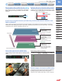
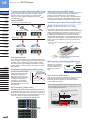
123
FIBER
SENSORS
Digital Fiber Sensor
FX-100 SERIES
Related Information
■ General terms and conditions............. P.1
■ Glossary of terms / General precautions...P.983~ / P.986~
■ Sensor selection guide........P.11~ / P.61~
■ Fiber selection................................. P.63~
LASER
SENSORS
PHOTOELECTRIC
SENSORS
MICRO
PHOTOELECTRIC
SENSORS
Conforming to
EMC Directive
AREA
SENSORS
SAFETY
COMPONENTS
PRESSURE
SENSORS
INDUCTIVE
PROXIMITY
SENSORS
PARTICULAR
USE SENSORS
SENSOR
OPTIONS
WIRE-SAVING
SYSTEMS
MEASUREMENT
SENSORS
SUNX website http://www.sunx.com
PNP output
type available
Timer
Automatic
sensitivity setting
Test input
Interference Light intensity
monitor
prevention
STATIC CONTROL
DEVICES
LASER
MARKERS
Taking fiber sensors to the next level
Setup is made simple, using a dual digital display
Selection
Guide
Fibers
The dual digital display allows users to check both the threshold
value and incident light intensity at the same time, allowing
for clear and intuitive control of the sensor’s functions. The
threshold value can be adjusted simply by pressing the
(UP)
key or the
(DOWN) key, so that the output operation can be
controlled with high precision, directly from the RUN mode.
Threshold value
Incident light intensity
FT / FD / FR
Fiber
Fiber Sensor
Sensor
Amplifi
ers
Amplifiers
FX-100
FX-300
FX-410
FX-311
FX-11A
FX-301-F
Other
Products
Commercially-available connectors are used so that lead time and spare part numbers
can both be reduced
The connectors used are commercially-available connectors,
so that processing costs and lead time required for carrying
out processing after purchase of the sensors can be greatly
reduced. The same connection parts as the DP-100 series
of digital pressure sensors and the PM-64 series of micro
photoelectric sensors can be used.
Connection with a
commercially-available
connector
Commercially-available press-fit connectors are used, so that the processing
costs for connection cables can be greatly reduced.
Conventional (cable type)
Conventional lead time
● Harness processing by outside order after sensor preparation
Customer Sensor preparation
1 Sensor purchase and preparation
2 Harness processing by outside order
Harness
processor
From now on (built-in connector type)
Sensor installation
Harness Processing
Lead time from now on
● Harness processing by outside order
Customer Sensor preparation
1 Sensor purchase and preparation
2 Harness processing by outside order
Harness
processor
Using cables with connectors
Sensor installation
Harness Processing
Lead time further reduced
Customer Sensor preparation Sensor installation
1 Purchase of sensors and cable with connectors
Reduced
Reduced
Reduced
lead time
Digital Fiber Sensor
FX-100 SERIES
ORDER GUIDE
LIST OF FIBERS
SPECIFICATIONS
I/O CIRCUIT DIAGRAMS
SENSING CHARACTERISTICS
PRECAUTIONS FOR PROPER USE
DIMENSIONS
P.126~
P.128~
P.133
P.134~
P.135~
P.136~
P.138
Saving-space with a width of 9 mm 0.354 in
Equipped with a four-chemical emitting element
The sensor is very slim, yet equipped with a dual digital
display. Both space saving and ease of use have been
achieved.
A stable amount of emitted light is ensured due to control
of the aging of the emitting element to the maximum limit.
[Stable sensing comparison]
AREA
SENSORS
Long-term
stability
SAFETY
COMPONENTS
A three level navigation structure provides easy access to the sensor’s functions, from
basic to advanced
Setting details are divided into three levels for simple operation, so that settings for normal operation are made in
“RUN mode”, basic settings are made in “SET mode”, and advanced functions are set in “PRO mode”. This makes
configuration much easier to understand and carry out.
Functions used during normal operation
[Function table]
• Changing threshold values • Key lock
• Quick settings • Code settings
SET mode
Functions used when initializing the
sensor and carrying out maintenance
[Function table]
SET MODE
PRESSURE
SENSORS
INDUCTIVE
PROXIMITY
SENSORS
PARTICULAR
USE SENSORS
SENSOR
OPTIONS
RUN mode
Simple setting
LASER
SENSORS
MICRO
PHOTOELECTRIC
SENSORS
Time
RUN MODE
FIBER
SENSORS
PHOTOELECTRIC
SENSORS
FX-100
Three-chemical
emitting element
Light-emitting
amount
9 mm
0.354 in
124
WIRE-SAVING
SYSTEMS
MEASUREMENT
SENSORS
STATIC CONTROL
DEVICES
LASER
MARKERS
• Teaching • L-ON / D-ON setting
• Timer setting
• Attenuation function
• Interference prevention function
PRO mode
Equipped with a full complement
of digital fiber sensor functions
PRO MODE
[Function table]
• Shift • External input • Reset
• GETA • ECO • Display reversing
• Surplus value display • Copy
• Threshold tracking
Special and detailed setting
Selection
Guide
Fibers
FT / FD / FR
Quick code input function [RUN mode]
Sensor settings can be made simply by selecting preset
values.
Fiber Sensor
sensor
Fiber
Amplifiers
Amplifiers
Quick setting numbers (summary)
No.
FX-100
Output
operation
Light-emitting
amount selection
Timer
Dark-ON
OFF
None
FX-410
Dark-ON
ON
None
FX-311
Dark-ON
OFF
OFF-delay 10 ms
FX-11A
Dark-ON
ON
OFF-delay 10 ms
FX-301-F
Light-ON
ON
ON-delay 40 ms
Other
Products
Light-ON
OFF
ON-delay 40 ms
Light-ON
ON
ON-delay 10 ms
Light-ON
OFF
ON-delay 10 ms
Smooth support via telephone [RUN mode]
Confirmation can be carried out smoothly via telephone
by simply quoting numbers. This can be of great
assistance when dealing with foreign country customers.
FX-300
125
FIBER
SENSORS
LASER
SENSORS
PHOTOELECTRIC
SENSORS
MICRO
PHOTOELECTRIC
SENSORS
Digital Fiber Sensor
FX-100 SERIES
Teaching using ON / OFF buttons [SET mode]
Attenuation function [SET mode]
Simply press the ON button when an object is present
and OFF when it is not. There is no need to switch
settings or make judgments between Light-ON (
)
and Dark-ON (
).
If the light receiving level becomes saturated when
sensing over short distances or when sensing
transparent objects or minute objects, the light emitting
amount can be reduced so that stable sensing can be
provided without needing to change the response time.
<Setting example>
Interference prevention function [SET mode]
Thru-beam type / Retroreflective type
AREA
SENSORS
FX-101□: Interference prevention for up to 3 units
FX-102□: Interference prevention for up to 4 units
SAFETY
COMPONENTS
PRESSURE
SENSORS
Object present ON
The emission frequencies can be set separately for
each unit in order to avoid interference. The emitted light
flashes while setting is in progress, so that you can see
at a glance which fiber sensor is currently being set.
In addition, this interference prevention is not done by
using optical communication. This means that there is no
need to place the amplifiers close together like there was
before, and so the amplifiers can be set up apart from
each other.
Object absent OFF
INDUCTIVE
PROXIMITY
SENSORS
PARTICULAR
USE SENSORS
Reflective type
SENSOR
OPTIONS
* When the emission frequencies are changed, the response times will
also change.
WIRE-SAVING
SYSTEMS
MEASUREMENT
SENSORS
Object present ON
Object absent OFF
STATIC CONTROL
DEVICES
LASER
MARKERS
Limit teaching function
This carries out teaching and sets threshold values only
when no object is present (when the incident light amount
is stable). This is useful when sensing objects if there
are other objects in the background and when sensing
minute objects. Teaching can also be carried out using
external input.
FT / FD / FR
Fiber
Fiber Sensor
Sensor
Amplifiers
Amplifi
ers
FX-100
FX-300
FX-410
FX-311
FX-11A
FX-301-F
Other
Products
Threshold tracking function [PRO mode]
This function seeks changes
in the light emitting amount
resulting from changes in
the environment over long
periods (such as dust levels),
so that the incident light
intensity can be checked
at desired intervals and the
threshold values can be reset
automatically.
Current value
The amount of light
received when there
is no object
Settings such as emission
halt, limit / auto teaching
and ECO settings can be
carried out via external
input.
(Brown) +V
(Black) Output
(White) External input
(Blue) 0 V
External input lines are
equipped as standard
Alert function [PRO mode]
When the amount light received approaches the
threshold value, the display can be made to blink in
order to alert the operator.
Threshold value
Time
GETA function [PRO mode]
The display value for the incident light intensity can be offset
by the desired value (target value). The target value can be set
to between 0 and 2,000 (in increments of 100). For example, if
the incident light intensity is 1,500 and the target value is set to
2,000, then “2,000” will appear in the digital display.
Variations in the amount of light received
Multi-function external input [PRO mode]
<When using at a shift amount of 20% and a threshold value of 1,000>
The amount of light received ranges from about 900 to 1,100
when the digital indicator flashes.
Incident light intensity
Fibers
Incident light intensity
Selection
Guide
The emitted light and output indicator flash
at the same frequency.
Range of the digital indicator flashing
(margin: small)
1,100 approx.
900 approx.
The digital indicator flashes.
Unify at 500 using
the GETA function
Threshold value
of 1,000
Digital Fiber Sensor
FX-100 SERIES
ORDER GUIDE
FIBER
SENSORS
Amplifiers
Appearance
M8 plug-in
connector
type
Cable set
(Note 1)
Standard type
M8 plug-in
connector
type
Type
M8 plug-in
connector
type
M8 plug-in
connector
type
Cable set
(Note 1)
LASER
SENSORS
Accessory
Emitting
element
Model No.
Output
FX-101 (Note 2)
NPN open-collector
transistor
FX-101-Z (Note 3)
NPN open-collector
transistor
FX-101P (Note 2)
PNP open-collector
transistor
FX-101P-Z (Note 3)
PNP open-collector
transistor
FX-101-CC2
NPN open-collector
transistor
FX-101P-CC2
PNP open-collector
collector transistor
Red LED
Long sensing range type
126
FX-102 (Note 2)
NPN open-collector
transistor
FX-102-Z (Note 3)
NPN open-collector
transistor
FX-102P (Note 2)
PNP open-collector
transistor
FX-102P-Z (Note 3)
PNP open-collector
transistor
FX-102-CC2
NPN open-collector
transistor
FX-102P-CC2
PNP open-collector
transistor
PHOTOELECTRIC
SENSORS
MICRO
PHOTOELECTRIC
SENSORS
• CN-14A-C2
Connector attached
cable 2 m 6.562 ft
* Only include cable set type
AREA
SENSORS
SAFETY
COMPONENTS
PRESSURE
SENSORS
INDUCTIVE
PROXIMITY
SENSORS
PARTICULAR
USE
SENSORS
SENSOR
OPTIONS
WIRESAVING
SYSTEMS
MEASUREMENT
SENSORS
STATIC
CONTROL
DEVICES
LASER
MARKERS
Notes: 1) The connector attached cable CN-14A-C2 is supplied with the amplifier.
2) Make sure to use the optional connector attached cable CN-14A(-R)-C□ or the connector CN-14A, or a connector manufactured by J.S.T. Mfg. Co., Ltd.
(contact: SPHD-001T-P0.5, housing: PAP-04V-S)
3) Make sure to use the optional M8 connector attached cable CN-24A-C□.
OPTIONS
M8 connector attached cable
Designation
Model No.
CN-14A-C1
Connector
attached cable
Description
31.4
1.236
1 m 3.281 ft
3 m 9.843 ft
CN-14A-C5
5 m 16.404 ft
CN-14A-R-C1
1 m 3.281 ft
CN-14A-R-C2
2 m 6.562 ft
CN-14A-R-C3
3 m 9.843 ft
CN-14A-R-C5
5 m 16.404 ft
M8 connector
attached cable
CN-24A-C2
2 m 6.562 ft
CN-24A-C5
5 m 16.404 ft
Connector
CN-14A
Set of 10 housings and 40 contacts
0.02 mm2 4-core cabtyre cable with connector
on one end
Cable outer diameter: ø3.7 mm ø0.146 in
FX-100
FX-300
FX-311
Fixing ring
FX-11A
For M8 plug-in connector type
The connector on one end
Cable outer diameter: ø4 mm ø0.157 in
This protects the operating surfaces.
Amplifier
MS-DIN-4
mounting bracket
Mounting bracket for amplifier
MS-DIN-E
Fiber
Fiber Sensor
Sensor
Amplifi
ers
Amplifiers
FX-410
Protection cover FC-FX-1
End plates
FT / FD / FR
M8 connector
attached cable
CN-24A-C□
ø9
ø0.354
Selection
Guide
Fibers
ø4
ø0.157
CN-14A-C2 (Note) 2 m 6.562 ft
CN-14A-C3
Connector
attached cable
(Flexible type)
• CN-24A-C□
Protection cover
Other
Products
• FC-FX-1
When it moves depending on the way it is installed on a DIN rail,
these end plates ensure that all amplifiers are mounted together
in a secure and fully connected manner.
Two pcs.per set
Amplifier mounting
bracket
Note: The connector attached cable CN-14A-C2 is supplied with the cable set type FX-10□(P)-CC2.
Recommended connector
Contact: SPHD-001T-P0.5, Housing: PAP-04V-S
(Manufactured by J.S.T. Mfg. Co., Ltd.)
Note: Contact the manufacturer for details of the recommended products.
• MS-DIN-4
Connector
attached cable
Connector
• CN-14A
• CN-14A(-R)-C□
Contact
Recommended crimping tool
Model No.: YC-610R
(Manufactured by J.S.T. Mfg. Co., Ltd.)
Note: Contact the manufacturer for details of the recommended products.
Housing
FX-301-F
127
FIBER
SENSORS
Digital Fiber Sensor
FX-100 SERIES
LIST OF FIBERS
LASER
SENSORS
Thru-beam type (one pair set)
PHOTOELECTRIC
SENSORS
MICRO
PHOTOELECTRIC
SENSORS
Fibers are listed in alphabetic order. Refer to p.63~ “Fiber Selection” for details of each fiber.
AREA
SENSORS
FT-A8
Model No.
FT-A30
SAFETY
COMPONENTS
PRESSURE
SENSORS
INDUCTIVE
PROXIMITY
SENSORS
PARTICULAR
USE
SENSORS
SENSOR
OPTIONS
WIRESAVING
SYSTEMS
MEASUREMENT
SENSORS
STATIC
CONTROL
DEVICES
LASER
MARKERS
FT-AFM2
FT-AFM2E
Fiber Sensor
sensor
Fiber
Ampilifi
ers
Amplifiers
FX-100
1,500 59.055 3,500 137.795 (Note 2)
P.106
FT-PS1
3,500 137.795 (Note 2) 3,500 137.795 (Note 2)
280 11.024
Sensing range (mm in) (Note 1)
Standard type FX-101□ Long sensing range type FX-102□
Dimensions
40 1.575
90 3.543
P.109
P.106
FT-R80
180 7.087
430 16.929
P.109
720 28.346
P.106
FT-SFM2
300 11.811
800 31.496
P.109
760 29.921
2,400 94.488
P.109
470 18.504
P.109
280 11.024
P.109
670 26.378
P.106
FT-SFM2L
1,150 45.276
P.106
FT-SFM2SV2
180 7.087
FT-E12
6 0.236
19 0.748
P.106
FT-SNFM2
130 5.118
FT-E22
15 0.591
60 2.362
P.106
FT-T80
300 11.811
800 31.496
P.109
P.106
FT-V10
1,000 39.370
2,350 92.520
P.109
P.106
FT-V22
140 5.512
380 14.961
P.109
P.106
FT-V41
40 1.575
120 4.724
P.109
340 13.386
800 31.496
P.109
80 3.150
220 8.661
P.109
260 10.236
FT-B8
FT-FM2
FT-FM2S
300 11.811
800 31.496
FT-FM2S4
FT-FM10L
9,300 366.141
15,000 590.550
P.106
FT-V80Y
250 9.843
700 27.559
P.106
FT-W4
P.107
FT-W8
135 5.315
420 16.535
P.107
FT-WA8
P.107
FT-WA30
210 8.268
540 21.260
P.107
150 5.906
500 19.685
FT-H20W-M1
100 3.937
300 11.811
FT-H30-M1V-S (Note 4)
110 4.331
280 11.024
FT-H13-FM2
FT-H20-J20-S (Note 3)
FT-H20-J30-S (Note 3)
FT-H20-J50-S (Note 3)
FT-H20-M1
FT-H35-M2
FT / FD / FR
Model No.
240 9.449
FT-H20-VJ80-S (Note 3)
Fibers
Standard type FX-101□ Long sensing range type FX-102□
Dimensions
400 15.748
FT-H20-VJ50-S (Note 3)
Selection
Guide
Sensing range (mm in) (Note 1)
FT-H35-M2S6
FT-HL80Y
FT-K8
650 25.591
P.110
1,500 59.055 3,500 137.795 (Note 2)
P.110
3,500 137.795 (Note 2) 3,500 137.795 (Note 2)
P.110
FT-WKV8
700 27.559
2,200 86.614
P.110
P.107
FT-WR80
215 8.465
570 22.441
P.110
P.107
FT-WR80L
430 16.929
1,150 45.276
P.110
P.107
FT-WS3
150 5.906
600 23.622
P.110
P.107
FT-WS4
80 3.150
220 8.661
P.110
P.107
FT-WS8
260 10.236
650 25.591
P.110
170 6.693
490 19.291
P.107
FT-WS8L
600 23.622
1,500 59.055
P.110
990 38.976
2,340 92.126
P.107
FT-WV42
30 1.181
80 3.150
P.110
230 9.055
670 26.378
P.110
80 3.150
230 9.055
P.111
330 12.992
1,000 39.370
P.111
190 7.480
580 22.835
P.111
1,000 39.370
3,000 118.110
P.108
FT-WZ4
FT-KV1
135 5.315
500 19.685
P.108
FT-WZ4HB
FT-KV8
1,000 39.370
3,000 118.110
P.108
FT-WZ7
FT-L80Y
1,100 43.307
2,600 102.362
P.108
FT-WZ7HB
P.108
FT-WZ8
330 12.992
950 37.402
P.111
130 5.118
280 11.024
P.108
FT-WZ8E
700 27.559
2,100 82.677
P.111
P.108
FT-WZ8H
1,200 47.244
2,800 110.236
P.111
FX-300
FT-NFM2
FX-410
FT-NFM2S
FX-311
FT-NFM2S4
FX-11A
FT-P2
120 4.724
330 12.992
P.108
FT-Z8
360 14.173
1,000 39.370
P.111
FX-301-F
FT-P40
80 3.150
240 9.449
P.108
FT-Z8E
800 31.496
1,850 72.835
P.111
FT-P60
130 5.118
300 11.811
P.108
FT-Z8H
1,400 55.118
3,100 122.047
P.111
FT-P80
230 9.055
650 25.591
P.108
FT-Z802Y
520 20.472
3,100 122.047
P.111
260 10.236
800 31.496
P.108
Other
Products
FT-P81X
Notes: 1) Please take care that the sensing range of the free-cut type fiber may be reduced by 20 % max. depending upon how the fiber is cut.
2) The fiber cable length practically limits the sensing range to 3,500 mm 137.795 in long.
3) Heat-resistant joint fibers and ordinary-temperature side fibers (FT-FM2) are sold as a set. Please refer to p.93~ for details.
4) Sold as a set comprising vacuum-resistant type fiber + photo-terminal (FV-BR1) + fiber at atmospheric side (FT-J8). Please refer to p.91~ for details.
Digital Fiber Sensor
FX-100 SERIES
LIST OF FIBERS
128
FIBER
SENSORS
Retroreflective type
LASER
SENSORS
Fibers are listed in alphabetic order. Refer to p.63~ “Fiber Selection” for details of each fiber.
PHOTOELECTRIC
SENSORS
MICRO
PHOTOELECTRIC
SENSORS
Model No.
FR-KV1
Sensing range (mm in) (Note 1, 2)
Standard type FX-101□
Long sensing range type FX-102□
Dimensions
15 to 200 0.591 to 7.874
15 to 360 0.591 to 14.173
P.112
FR-KZ21
200 7.874
200 7.874
P.112
FR-KZ21E
200 7.874
200 7.874
P.112
100 to 550 3.937 to 21.654
100 to 830 3.937 to 32.677
P.112
FR-WKZ11
AREA
SENSORS
SAFETY
COMPONENTS
PRESSURE
SENSORS
Notes: 1) Please take care that the sensing range of the free-cut type fiber may be reduced by 20 % max. depending upon how the fiber is cut.
The sensing range of FR-WKZ11 is specified for the RF-13. The sensing range of FR-KZ21, FR-KZ21E and FR-KV1 is specified for the attached reflector.
The sensing ranges when using in combination with the FR-WKZ11 reflector (optional) are given in the below table.
Amplifier
FX-101□
FX-102□
100 to 700 3.937 to 27.559
100 to 1,100 3.937 to 43.307
FR-WKZ11 + RF-220 100 to 1,300 3.937 to 51.181
100 to 2,600 3.937 to 102.362
FR-WKZ11 + RF-230 100 to 2,000 3.937 to 78.740
100 to 4,000 3.937 to 157.480
Reflector
FR-WKZ11 + RF-210
INDUCTIVE
PROXIMITY
SENSORS
PARTICULAR
USE
SENSORS
SENSOR
OPTIONS
2) The sensing range of FR-WKZ11 is the possible setting range for the reflector or reflective tape. The fiber can detect an object less than 100 mm 3.937 in away.
However, note that if there are any white or highly-reflective surfaces near the fiber head, reflected incident light may affect the fiber head. If this occurs,
adjust the threshold value of the amplifier unit before use.
The sensing range of FR-KZ21(E) is the possible setting range for the reflector. However, if setting the fiber to detect objects passing within 0 to 20 mm
0 to 0.787 in from the fiber head, unstable detection may result.
The sensing range of FR-KV1 is the possible setting range for the reflector. The fiber can detect an object less than 15 mm 0.591 in away.
WIRESAVING
SYSTEMS
MEASUREMENT
SENSORS
STATIC
CONTROL
DEVICES
LASER
MARKERS
Reflective type
Fibers are listed in alphabetic order. Refer to “Fiber Selection p.63~” for details of each fiber.
Model No.
Sensing range (mm in) (Note 1, 2)
Standard type FX-101□ Long sensing range type FX-102□
Dimensions
Model No.
Sensing range (mm in) (Note 1, 2)
Standard type FX-101□ Long sensing range type FX-102□
Dimensions
FD-A15
125 4.921
250 9.843
P.113
FD-G6
50 1.969
120 4.724
P.114
FD-AFM2
105 4.134
285 11.220
P.113
FD-G6X
45 1.772
160 6.299
P.114
85 3.346
245 9.646
P.113
FD-H13-FM2
100 3.937
280 11.024
P.114
FD-B8
170 6.693
440 17.323
P.113
FD-H18-L31
FD-E12
3.5 0.138
13 0.512
P.113
FD-H20-21
90 3.543
280 11.024
P.115
FD-E22
16 0.630
45 1.772
P.113
FD-H20-M1
120 4.724
300 11.811
P.115
FD-EG1
18 0.709
50 1.969
P.113
FD-H30-KZ1V-S (Note 3) 25 to 80 0.984 to 3.150 10 to 220 0.394 to 8.661
P.115
FD-EG2
10 0.394
30 1.181
P.113
FD-H30-L32
2 to 9 0.079 to 0.354
0 to 17 0 to 0.669
P.115
FD-EG3
7 0.276
22 0.866
P.113
FD-H30-L32V-S (Note 3) 2.5 to 6.5 0.098 to 0.256
0 to 11 0 to 0.433
P.115
FD-EN500S1
1 0.039
4 0.157
P.113
FD-H35-20S
FD-ENM1S1
15 0.591
48 1.890
P.114
FD-H35-M2
FD-AFM2E
FD-F4
FD-F41
FD-F8Y
FD-FM2
FD-FM2S
FD-FM2S4
FD-G4
Applicable pipe diameter:
Outer dia. ø6 to ø26 mm ø0.236 to
ø1.024 in transparent pipe
[PFA (fluorine resin) or equivalently
transparent pipe, wall thickness 1 mm
0.039 in]
FD-H35-M2S6
P.114
P.116
FD-L43
0 to 19 0 to 0.748
0 to 25 0 to 0.984
P.116
FD-L44
0 to 6 0 to 0.236
0 to 8 0 to 0.315
P.116
FD-L44S
0 to 4.5 0 to 0.177
0 to 5.5 0 to 0.217
P.116
FD-L45
0 to 40 0 to 1.575
0 to 50 0 to 1.969
P.116
16 to 30 0.630 to 1.181 12 to 50 0.472 to 1.969
P.116
FD-L46
FD-NFM2
P.114
FD-NFM2S
P.114
FD-NFM2S4
P.114
FD-P2
120 4.724
P.116
3 to 14 0.118 to 0.551 1.5 to 16 0.059 to 0.630
(Convergent point 8 0.315) (Convergent point 8 0.315)
P.114
50 1.969
P.116
FD-L41
P.114
345 13.583
280 11.024
P.116
P.116
–
100 3.937
75 2.953
200 7.874
P.115
5 to 8 0.197 to 0.315 1 to 17 0.039 to 0.669
(Convergent point 6 0.236) (Convergent point 6 0.236)
P.114
410 16.142
85 3.346
0 to 25 0 to 0.984
FD-L4
Applicable pipe diameter:
Outer dia. ø6 to ø26 mm ø0.236 to
ø1.024 in transparent pipe
[PVC (vinyl chloride), fluorine resin,
polycarbonate, acrylic, glass, wall
thickness 1 to 3 mm 0.039 to 0.118 in]
100 3.937
0 to 10 0 to 0.394
P.117
35 1.378
100 3.937
P.117
P.117
25 0.984
65 2.559
P.117
Notes: 1) The standard sensing objects of the sensing ranges vary depending on the fibers. Refer to p.71~ for details.
2) Please take care that the sensing range of the free-cut type fiber may be reduced by 20 % max. depending upon how the fiber is cut.
3) Sold as a set comprising vacuum-resistant type fiber + photo-terminal (FV-BR1) + fiber at atmospheric side (FT-J8). Please refer to p.91~ for details.
Selection
Guide
Fibers
FT / FD / FR
Fiber
Fiber Sensor
Sensor
Amplifi
ers
Amplifiers
FX-100
FX-300
FX-410
FX-311
FX-11A
FX-301-F
Other
Products
129
FIBER
SENSORS
Digital Fiber Sensor
FX-100 SERIES
LIST OF FIBERS
LASER
SENSORS
Reflective type
PHOTOELECTRIC
SENSORS
MICRO
PHOTOELECTRIC
SENSORS
Fibers are listed in alphabetic order. Refer to “Fiber Selection p.63~” for details of each fiber.
AREA
SENSORS
SAFETY
COMPONENTS
PRESSURE
SENSORS
INDUCTIVE
PROXIMITY
SENSORS
PARTICULAR
USE
SENSORS
SENSOR
OPTIONS
WIRESAVING
SYSTEMS
MEASUREMENT
SENSORS
STATIC
CONTROL
DEVICES
LASER
MARKERS
Selection
Guide
Fibers
FT / FD / FR
Fiber Sensor
sensor
Fiber
Ampilifi
ers
Amplifiers
FX-100
FX-300
FX-410
FX-311
FX-11A
FX-301-F
Other
Products
Model No.
Sensing range (mm in) (Note 1, 2)
Standard type FX-101□ Long sensing range type FX-102□
Dimensions
Model No.
FD-P40
8 0.315
30 1.181
P.117
FD-WG4
FD-P50
45 1.772
150 5.906
P.117
FD-P60
45 1.772
150 5.906
P.117
FD-P80
90 3.543
200 7.874
P.117
FD-P81X
70 2.756
220 8.661
P.117
FD-R80
70 2.756
180 7.087
P.117
FD-S80
100 3.937
345 13.583
P.117
FD-SFM2SV2
30 1.181
90 3.543
P.117
FD-SNFM2
35 1.378
100 3.937
P.118
FD-T40
35 1.378
100 3.937
P.118
FD-T80
100 3.937
345 13.583
P.118
FD-V41
25 0.984
70 2.756
P.118
FD-W8
80 3.150
230 9.055
P.118
FD-W44
15 0.591
40 1.575
P.118
Sensing range (mm in) (Note 1, 2)
Standard type FX-101□ Long sensing range type FX-102□
28 1.102
75 2.953
Dimensions
P.118
FD-WKZ1
20 to 180 0.787 to 7.087 20 to 480 0.787 to 18.898
P.118
FD-WL41
7 to 12 0.276 to 0.472 6 to 13.5 0.236 to 0.531
(Convergent point 8 0.315) (Convergent point 8 0.315)
P.118
FD-WL48
1 to 4.5 0.039 to 0.177 0.5 to 6.5 0.020 to 0.256
P.119
FD-WS8
80 3.150
230 9.055
P.119
FD-WSG4
28 1.102
75 2.953
P.119
FD-WT4
15 0.591
40 1.575
P.119
FD-WT8
80 3.150
230 9.055
P.119
6 0.236
20 0.787
P.119
FD-WV42
FD-WZ4
FD-WZ4HB
2 to 20 0.079 to 0.787 1 to 70 0.039 to 2.756
FD-WZ7
1 to 55 0.039 to 2.165
FD-WZ7HB
1 to 60 0.039 to 2.362 0.5 to 180 0.020 to 7.087
160 6.299
P.119
P.119
P.119
P.119
Notes: 1) The standard sensing objects of the sensing ranges vary depending on the fibers. Refer to p.71~ for details.
2) Please take care that the sensing range of the free-cut type fiber may be reduced by 20 % max. depending upon how the fiber is cut.
3) Sold as a set comprising vacuum-resistant type fiber + photo-terminal (FV-BR1) + fiber at atmospheric side (FT-J8). Please refer to p.91~ for details.
Digital Fiber Sensor
FX-100 SERIES
130
FIBER OPTIONS
FIBER
SENSORS
Lens (For thru-beam type fiber)
Designation
The dimensions are on p.120~.
Model No.
Description
Sensing range (mm in) [Lens on both sides]
Fiber
Increases the sensing
range by 5 times or more.
Expansion
lens
(Note 1)
FX-LE1
• Ambient temperature:
–60 to +350 °C
–76 to +662 °F
(Note 3)
Amplifier
FX-101□
FX-102□
FT-B8
2,200 86.614
3,500 137.795 (Note 2)
FT-FM2, FT-T80
3,000 118.110
3,500 137.795 (Note 2)
FT-R80
1,900 74.803
3,500 137.795 (Note 2)
FT-W8
3,000 118.110
3,500 137.795 (Note 2)
FT-P80, FT-P60
3,500 137.795 (Note 2) 3,500 137.795 (Note 2)
FT-P81X
1,600 62.992 (Note 2) 1,600 62.992 (Note 2)
FT-H35-M2
2,000 78.740
3,500 137.795 (Note 2)
FT-H20W-M1
1,300 51.181
1,600 62.992 (Note 2)
FT-H20-M1
1,600 62.992 (Note 2) 1,600 62.992 (Note 2)
FT-H20-J20-S, FT-H20-J30-S, FT-H20-J50-S 1,000 39.370
3,500 137.795 (Note 2)
LASER
SENSORS
PHOTOELECTRIC
SENSORS
MICRO
PHOTOELECTRIC
SENSORS
AREA
SENSORS
SAFETY
COMPONENTS
PRESSURE
SENSORS
INDUCTIVE
PROXIMITY
SENSORS
PARTICULAR
USE
SENSORS
SENSOR
OPTIONS
For thru-beam type fiber
Sensing range (mm in) [Lens on both sides]
Superexpansion
lens
(Note 1)
FX-LE2
Amplifier
FX-101□
FX-102□
Tremendously increases the
sensing range with large
diameter lenses.
Fiber
FT-P81X
1,600 62.992 (Note 2) 1,600 62.992 (Note 2)
• Ambient temperature:
–60 to +350 °C
–76 to +662 °F
(Note 3)
FT-H35-M2
3,500 137.795 (Note 2) 3,500 137.795 (Note 2)
FT-B8, FT-FM2, FT-R80, FT-W8, FT-P80, FT-P60 3,500 137.795 (Note 2) 3,500 137.795 (Note 2)
FT-H20W-M1, FT-H20-M1 1,600 62.992 (Note 2) 1,600 62.992 (Note 2)
3,500 137.795 (Note 2) 3,500 137.795 (Note 2)
FT-H13-FM2
FT-H20-J20-S, FT-H20-J30-S, FT-H20-J50-S 3,500 137.795 (Note 2) 3,500 137.795 (Note 2)
WIRESAVING
SYSTEMS
MEASUREMENT
SENSORS
STATIC
CONTROL
DEVICES
LASER
MARKERS
Sensing range (mm in) [Lens on both sides]
Side-view
lens
FX-SV1
Amplifier
FX-101□
FX-102□
FT-B8
530 20.866
1,450 57.087
Fiber
FT-FM2, FT-T80
550 21.654
1,700 66.929
Beam axis is bent by 90°.
FT-W8
450 17.717
1,300 51.181
• Ambient temperature:
–60 to +300 °C
–76 to +572 °F
(Note 3)
FT-P80
420 16.535
1,400 55.118
FT-P60
300 11.811
850 33.465
FT-P81X
550 21.654
1,700 66.929
FT-H35-M2
280 11.024
800 31.496
FT-H20W-M1
FT-H20-M1
FT-H20-J20-S, FT-H20-J30-S, FT-H20-J50-S
Expansion
lens for vacuumresistant fiber
(Note 1)
Side-view
lens for
vacuumresistant fiber
FV-LE1
FV-SV2
140 5.512
400 15.748
FT / FD / FR
840 33.071
150 5.906
410 16.142
Fiber
Fiber Sensor
Sensor
Amplifi
ers
Amplifiers
Sensing range (mm in) [Lens on both sides] (Note 4)
Fiber
• Ambient temperature:
–60 to +300 °C –76 to +572 °F FT-H30-M1V
(Note 3)
Amplifier
Fibers
280 11.024
Sensing range increases by
Sensing range (mm in) [Lens on both sides] (Note 4)
4 times or more.
Amplifier
FX-101□
FX-102□
Fiber
• Ambient temperature:
–60 to +350 °C –76 to +662 °F FT-H30-M1V
450 17.717
1,600 62.992
(Note 3)
Beam axis is bent by 90°.
Selection
Guide
FX-100
FX-300
FX-410
FX-311
FX-11A
FX-101□
FX-102□
FX-301-F
450 17.717
1,600 62.992
Other
Products
Notes: 1) Be careful when installing the thru-beam type fiber equipped with the expansion lens, as the beam envelope becomes narrow and alignment is difficult.
Especially when installing a fiber with many cores (sharp bending fibers and heat-resistant glass fiber), please be sure to use it only after you have
adjusted it sufficiently.
2) The fiber cable length practically limits the sensing range to 3,500 mm 137.795 in long (FT-H20W-M1, FT-P81X and FT-H20-M1: 1,600 mm 62.992 in).
3) For details on the ambient temperatures for the fibers which being combined, refer to p.101~.
4) The fiber cable length for the FT-H30-M1V is 1 m 3.281 ft. The sensing ranges in FX-102□ (long sensing range type) take into account the length of the
FT-J8 atmospheric side fiber.
131
Digital Fiber Sensor
FIBER OPTIONS
FIBER
SENSORS
LASER
SENSORS
PHOTOELECTRIC
SENSORS
MICRO
PHOTOELECTRIC
SENSORS
FX-100 SERIES
Lens (For reflective type fiber)
Designation
Pinpoint spot
lens
AREA
SENSORS
The dimensions are on p.121~.
Model No.
Description
Pinpoint spot of ø0.5 mm ø0.020 in. Enables detection of minute objects or small marks.
• Distance to focal point: 6 ± 1 mm 0.236 ± 0.039 in • Applicable fibers: FD-WG4, FD-G4
• Ambient temperature: –40 to +70 °C –40 to +158 °F (Note 2)
FX-MR1
Sensing range for FX-101□ (mm in) (Note 1)
SAFETY
COMPONENTS
The spot diameter is adjustable from ø0.7 to
ø2 mm ø0.028 to ø0.079 in according to how
much the fiber is screwed in.
• Applicable fibers: FD-WG4, FD-G4
• Ambient temperature: –40 to +70 °C
Spot
–40 to +158 °F (Note 2)
diameter
• Accessory: MS-EX-3 (mounting bracket)
Screw-in
depth
PRESSURE
SENSORS
Zoom lens
INDUCTIVE
PROXIMITY
SENSORS
FX-MR2
Distance to
focal point
PARTICULAR
USE
SENSORS
For reflective type fiber
LASER
MARKERS
Finest spot
lens
Extremely fine spot of ø0.3 mm ø0.012 in
approx. achieved.
• Applicable fibers: FD-WG4, FD-G4, FD-EG1,
FD-EG2, FD-EG3, FD-G6X, FD-G6
• Ambient temperature: –40 to +70 °C
–40 to +158 °F (Note 2)
FX-MR3
Distance to
focal point
Finest spot
lens
Extremely fine spot of ø0.1 mm ø0.004 in
approx. achieved.
• Applicable fibers: FD-WG4, FD-G4, FD-EG1,
FD-EG2, FD-EG3, FD-G6X, FD-G6
• Ambient temperature: –20 to +60 °C
–4 to +140 °F (Note 2)
FX-MR6
Fibers
FT / FD / FR
Screw-in
depth
FX-100
FX-311
FX-301-F
Other
Products
ø1.2 ø0.047
14 mm 0.551 in
43 1.693
approx.
ø2.0 ø0.079
FD-EG3
7.5 ± 0.5
ø0.15 ø0.006
0.295 ± 0.020 approx.
FD-EG2
7.5 ± 0.5
ø0.2 ø0.008
0.295 ± 0.020 approx.
FD-EG1
7.5 ± 0.5
ø0.3 ø0.012
0.295 ± 0.020 approx.
FD-WG4/G4,
FD-G6X/G6
7.5 ± 0.5
ø0.5 ø0.020
0.295 ± 0.020 approx.
FD-EG3
7 ± 0.5
ø0.1 ø0.004
0.276 ± 0.020 approx.
FD-EG2
7 ± 0.5
ø0.15 ø0.006
0.276 ± 0.020 approx.
FD-EG1
7 ± 0.5
ø0.2 ø0.008
0.276 ± 0.020 approx.
FD-WG4/G4,
FD-G6X/G6
7 ± 0.5
ø0.4 ø0.016
0.276 ± 0.020 approx.
Sensing range for FX-101□ (mm in) (Note 1)
Fiber Sensor
sensor
Fiber
Ampilifi
ers
Amplifiers
FX-11A
27 1.063
approx.
Fiber model No. Distance to focal point Spot diameter
Selection
Guide
FX-410
12 mm 0.472 in
Sensing range for FX-101□ (mm in) (Note 1)
Spot diameter
FX-300
ø0.7 ø0.028
Fiber model No. Distance to focal point Spot diameter
WIRESAVING
SYSTEMS
STATIC
CONTROL
DEVICES
18.5 0.728
approx.
7 mm 0.276 in
Sensing range for FX-101□ (mm in) (Note 1)
SENSOR
OPTIONS
MEASUREMENT
SENSORS
Screw-in depth Distance to focal point Spot diameter
Zoom lens
Side-view
type
FX-MR5
Distance
to focal
point
Spot diameter
Screw-in depth Distance to focal point Spot diameter
FX-MR2 is converted into a side-view type
and can be mounted in a very small space.
• Applicable fibers: FD-WG4, FD-G4
• Ambient temperature: –40 to +70 °C
–40 to +158 °F (Note 2)
8 mm 0.315 in
13 0.512
approx.
ø0.5 ø0.020
10 mm 0.394 in
15 0.591
approx.
ø0.8 ø0.031
14 mm 0.551 in
30 1.181
approx.
ø3.0 ø0.118
Notes: 1) The sensing ranges are the values when used in combination with FX-101□ (standard type). Please contact our office for details on sensing ranges for
other types of amplifier.
2) For details on the ambient temperatures for the fibers which being combined, refer to p.101~.
Digital Fiber Sensor
SPECIFICATIONS
Standard type
Model No.
Long sensing range type
Cable set
Cable set
NPN output
FX-101(-Z) (Note 4)
FX-101-CC2
PNP output
FX-101P(-Z) (Note 4)
FX-101P-CC2
Supply voltage
Power consumption
Output
12 to 24 V DC ± 10 %
<NPN output type>
NPN non-contact input
• Signal condition
High: +8 V to +V DC or Open
Low: 0 to +2 V DC
(Source current 0.5 mA or less)
• Input impedance: 10 kΩ approx.
PHOTOELECTRIC
SENSORS
MICRO
PHOTOELECTRIC
SENSORS
AREA
SENSORS
SAFETY
COMPONENTS
PRESSURE
SENSORS
INDUCTIVE
PROXIMITY
SENSORS
SENSOR
OPTIONS
WIRESAVING
SYSTEMS
MEASUREMENT
SENSORS
STATIC
CONTROL
DEVICES
LASER
MARKERS
4 digits (green) + 4 digits (red) LCD display
Incorporated
ON-delay / OFF-delay timer, switchable either effective or ineffective
[Timer period: 1 ms, 5 ms, 10 ms, 20 ms, 40 ms, 50 ms, 100 ms, 500 ms, 1,000 ms]
Incorporated
Switchable either effective or ineffective
Attenuation function
Incorporated
Emission frequency selection method (Note 2)
(Functions at emission frequency 1, 2 or 3)
Incorporated
Emission frequency selection method (Note 2)
(Functions at emission frequency 1, 2, 3 or 4)
Selection
Guide
Fibers
FT / FD / FR
–10 to +55 °C +14 to +131 °F (If 4 to 7 units are mounted close together: –10 to +50 °C +14 to +122 °F, if 8 to 16 units are mounted close together:
–10 to +45 °C +14 to +113 °F) (No dew condensation or icing allowed), Storage: –20 to +70 °C –4 to +158 °F
Fiber
Fiber Sensor
Sensor
Amplifi
ers
Amplifiers
Ambient humidity
35 to 85 % RH, Storage: 35 to 85 % RH
FX-100
Incandescent light: 3,000 ℓx at the light-receiving face
FX-300
1,000 V AC for one min. between all supply terminals connected together and enclosure (Note 3)
FX-410
Ambient illuminance
Insulation resistance
20 MΩ, or more, with 250 V DC megger between all supply terminals connected together and enclosure (Note 3)
Vibration resistance
10 to 150 Hz frequency, 0.75 mm 0.030 in amplitude in X, Y and Z directions for two hours each
Shock resistance
98 m/s2 acceleration (10 G approx.) in X, Y and Z directions for five times each
Emitting element (modulated)
Red LED (Peak emission wavelength: 632 nm 0.025 mil)
Material
Connector (Note 4)
Cable length
FX-311
FX-11A
FX-301-F
Enclosure: Polycarbonate, Key switch: Polycarbonate, Fiber lock lever: PBT
Connecting method
Accessory
LASER
SENSORS
Orange LED (lights up when the output is ON)
Timer function
Environmental resistance
Emission frequency 1: 2.5 ms or less (factory default setting)
Emission frequency 2: 2.8 ms or less
Emission frequency 3: 3.2 ms or less
Emission frequency 4: 5.0 ms or less
2-level teaching / Limit teaching / Full-auto teaching
Fine sensitivity adjustment function
Weight
FIBER
SENSORS
PARTICULAR
USE
SENSORS
<PNP output type>
PNP non-contact input
• Signal condition
High: +4 V to +V DC
(Sink current 0.5 to 3 mA)
Low: 0 to +0.6 V DC or Open
• Input impedance: 10 kΩ approx.
Emission frequency 0: 250 μs or less (factory default setting)
Emission frequency 1: 450 μs or less
Emission frequency 2: 500 μs or less
Emission frequency 3: 600 μs or less
Digital display
Voltage withstandability
FX-102P-CC2
Incorporated
Operation indicator
Ambient temperature
FX-102P(-Z) (Note 4)
Ripple P-P 10 % or less
Selectable either Light-ON or Dark-ON, at SET mode
Sensitivity setting
Interference prevention
function
FX-102-CC2
<NPN output type>
<PNP output type>
NPN open-collector transistor
PNP open-collector transistor
• Maximum sink current: 100 mA
• Maximum source current: 100 mA
• Applied voltage: 30 V DC or less (between output and 0 V)
• Applied voltage: 30 V DC or less (between output and +V)
• Residual voltage: 1.5 V or less (at 100 mA sink current)
• Residual voltage: 1.5 V or less (at 100 mA source current)
Short-circuit protection
Response time
FX-102(-Z) (Note 4)
Normal operation: 720 mW or less (Current consumption 30 mA or less at 24 V supply voltage)
ECO mode: 600 mW or less (Current consumption 25 mA or less at 24 V supply voltage)
Output operation
External input
132
Refer to p.101~ for fiber specifications.
Type
Item
FX-100 SERIES
Total length up to 100 m 328.084 ft is possible with 0.3 mm2, or more, cable.
Net weight: 15 g approx.
Gross weight: 35 g approx.
Net weight: 15 g approx.
Gross weight: 75 g approx.
Net weight: 15 g approx.
Gross weight: 35 g approx.
Net weight: 15 g approx.
Gross weight: 75 g approx.
–
CN-14A-C2
(Connector attached cable, 2 m 6.562 ft long): 1pc.
–
CN-14A-C2
(Connector attached cable, 2 m 6.562 ft long): 1pc.
Notes: 1) Where measurement conditions have not been specified precisely, the conditions used were an ambient temperature of +23 °C +73.4 °F.
2) When using the interference prevention function, set the emission frequencies for the amplifiers to be covered by the interference prevention function to
different frequency values.
However, the interference prevention function does not operate at emission frequency 0 (factory default setting) for the FX-101(P)(-Z) / FX-101(P)-CC2.
3) The voltage withstandability and the insulation resistance values given in the above table are for the amplifier only.
4) Connector attached cable CN-14A-C2 is not attached to the models that have no “-CC2” at the end of the model Nos.
Make sure to use the optional connector attached cable CN-14A(-R)-C□ or the connector CN-14A, or a connector manufactured by J.S.T. Mfg., Ltd.
(contact: SPHD-001T-P0.5, housing: PAP-04V-S).
Model Nos. having the suffix “-Z” are M8 plug-in connector type. Make sure to use the optional M8 attached connector cable CN-24A-C□.
Other
Products
133
Digital Fiber Sensor
I/O CIRCUIT AND WIRING DIAGRAMS
FIBER
SENSORS
LASER
SENSORS
PHOTOELECTRIC
SENSORS
MICRO
PHOTOELECTRIC
SENSORS
FX-10□(-Z/-CC2)
NPN output type
I/O circuit diagram
Terminal arrangement diagram
Color code of cable with connector
1
Sensor circuit
PRESSURE
SENSORS
2
Tr
+8 V
(Black) Output
Load
+
–
100 mA max.
ZD
3
4
INDUCTIVE
PROXIMITY
SENSORS
WIRESAVING
SYSTEMS
Terminal No.
(Brown) +V
D
SAFETY
COMPONENTS
SENSOR
OPTIONS
Connector type
Terminal No.
AREA
SENSORS
PARTICULAR
USE
SENSORS
FX-100 SERIES
(White) Extemal input
12 to 24 V DC
± 10 %
1
1
+V
2
2
Output
3
3
External input
4
0V
Terminal No.
Function
1
+V
2
Output
3
External input
4
0V
4
*1
(Blue) 0 V
Internal circuit
Function
Users’ circuit
M8 plug-in connector type
Symbols … D : Reverse supply polarity protection diode
ZD: Surge absorption zener diode
Tr : NPN output transistor
*1
1
2
Non-voltage contact or NPN open-collector transistor
MEASUREMENT
SENSORS
or
STATIC
CONTROL
DEVICES
High (+8 V to +V DC, or open): Ineffective
Low [(0 to +2 V DC (source current 0.5 mA or less)]: Effective
3
4
LASER
MARKERS
FX-10□P(-Z/-CC2)
PNP output type
I/O circuit diagram
Terminal arrangement diagram
Connector type
Terminal No.
Color code of cable with connector
Terminal No.
Function
1
1
+V
2
2
Output
3
3
External input
4
0V
Terminal No.
Function
(Brown) +V
Sensor circuit
*1
Selection
Guide
Fibers
FT / FD / FR
3
ZD
Tr
100 mA max.
2
D
4
Fiber Sensor
sensor
Fiber
Ampilifi
ers
Amplifiers
(White) External input
(Black) Output
(Blue) 0 V
Internal circuit
Load
FX-410
FX-301-F
Other
Products
4
M8 plug-in connector type
Symbols … D : Reverse supply polarity protection diode
ZD: Surge absorption zener diode
Tr : PNP output transistor
FX-311
FX-11A
12 to 24 V DC
± 10 %
Users’ circuit
FX-100
FX-300
+
–
1
*1
Non-voltage contact or PNP open-collector transistor
3
or
High [ +4 V to +V DC (sink current 0.5 to 3 mA)]: Effective
Low (0 to +0.6 V DC, or open): Ineffective
1
+V
2
Output
3
External input
4
0V
2
4
SENSING CHARACTERISTICS (TYPICAL)
FT-A8
• Horizontal direction
FT-B8
FT-FM2 FT-FM2S FT-FM2S4 Thru-beam
type
FT-SFM2 FT-T80
Thru-beam type
Parallel deviation
Parallel deviation
1,000
39.370
3,000
118.11
2,000
78.74
FX-101
Fiber
head
1,000
39.37
ℓ 8 mm 0.315 in
approx.
L
2,000
78.74
Fiber
head
ℓ
1,000
39.37
L
1,000
39.370
FX-102
FX-101
Fiber
head
500
19.685
ℓ
L
Fiber
head
Fiber
head
Fiber head
0
200
100
0
100
200
7.874
3.937
3.937
7.874
Down
Center
Up
Operating point ℓ (mm in)
0
200
7.874
FT-NFM2 FT-NFM2S
Thru-beam
FT-NFM2S4 FT-SNFM2 type
Parallel deviation
FX-101
0
1,000
39.37
100
0
100
200
3.937
3.937
7.874
Left
Center
Right
Operating point ℓ (mm in)
FT-P81X
FX-101
ℓ
100
3.937
L
FX-101
500
19.685
ℓ
L
Fiber
head
0
400
15.748
100
100
200
3.937
3.937
7.874
Left
Center
Right
Operating point ℓ (mm in)
FD-B8
Sensing field
Fiber
head
ℓ
L
0
100
3.937
200
0
200
400
7.874
7.874 15.748
Left
Center
Right
Operating point ℓ (mm in)
White non-glossy paper
ℓ
L
Fiber
head
0
100
3.937
50
0
50
100
1.969
1.969
3.937
Left
Center
Right
Operating point ℓ (mm in)
FD-NFM2 FD-NFM2S FD-NFM2S4 Reflective
type
FD-SNFM2 FD-T40
Sensing field
FX-101
200
7.874
White non-glossy paper
ℓ
L
Fiber
head
Setting distance L (mm in)
FX-101
200
7.874
0
100
3.937
Setting distance L (mm in)
Setting distance L (mm in)
FX-102
50
1.969
White non-glossy paper
ℓ
L
Fiber
head
Selection
Guide
Fibers
FT / FD / FR
150
5.906
Fiber
Fiber Sensor
Sensor
Amplifi
ers
Amplifiers
100
3.937
50
1.969
0
40
1.575
20
0
20
40
0.787
0.787
1.575
Left
Center
Right
Operating point ℓ (mm in)
Sensing field
FX-102
FX-100
FX-101 White non-glossy paper
ℓ
L
Fiber
head
FX-300
FX-410
FX-311
20
0
20
40
0.787
0.787 1.575 FX-11A
Left
Center
Right
Operating point ℓ (mm in)
FX-301-F
FD-WG4 FD-WSG4 Reflective type
Other
Products
Sensing field
10
0
10
20
0.394
0.394
0.787
Left
Center
Right
Operating point ℓ (mm in)
FX-102
FX-101
100
3.937
0
40
1.575
White non-glossy paper
ℓ
L
Fiber
head
20
0
20
40
0.787
0.787
1.575
Left
Center
Right
Operating point ℓ (mm in)
200
7.874
FX-102
FX-101
100
3.937
0
40
1.575
White non-glossy paper
ℓ
L
Fiber
head
20
0
20
40
0.787
0.787
1.575
Left
Center
Right
Operating point ℓ (mm in)
Setting distance L (mm in)
White non-glossy paper
ℓ
L
Fiber
head
200
7.874
Setting distance L (mm in)
FX-101
Setting distance L (mm in)
Setting distance L (mm in)
Reflective type
80
3.150
100
3.937
0
20
0.787
100
0
100
200
3.937
3.937 7.874
Left
Center
Right
Operating point ℓ (mm in)
FD-G6X
FX-102
50
1.969
L
200
7.874
FX-101
LASER
MARKERS
ℓ
Sensing field
FD-W8 FD-WS8 FD-WT8 Reflective type
Reflective type
Sensing field
100
3.937
0
40
1.575
50
0
50
100
1.969
1.969
3.937
Left
Center
Right
Operating point ℓ (mm in)
FD-P81X
Fiber
head
200
7.874
0
200
7.874
FX-102
FX-102
SENSOR
OPTIONS
Fiber
head
Reflective type
Sensing field
400
15.748
400
15.748
FX-101
400
15.748
50
0
50
100
1.969
1.969
3.937
Left
Center
Right
Operating point ℓ (mm in)
FD-G4
Reflective type
Sensing field
100
3.937
PRESSURE
SENSORS
STATIC
CONTROL
DEVICES
FX-102
Fiber
head
Fiber
head
FD-FM2
Reflective type
Fiber
head
Setting distance L (mm in)
Fiber
head
SAFETY
COMPONENTS
MEASUREMENT
SENSORS
600
23.622
FX-101
Setting distance L (mm in)
FX-101
FX-102
Setting distance L (mm in)
FX-102
200
7.874
Setting distance L (mm in)
Setting distance L (mm in)
300
11.811
FX-102
200
7.874
PHOTOELECTRIC
SENSORS
MICRO
PHOTOELECTRIC
SENSORS
WIRESAVING
SYSTEMS
Parallel deviation
800
9.843
1,000
39.370
LASER
SENSORS
INDUCTIVE
PROXIMITY
200
0
200
400 SENSORS
7.874
7.874 15.748
PARTICULAR
Left
Center
Right
USE
Operating point ℓ (mm in)
SENSORS
FT-W8 FT-WS8 Thru-beam type
400
15.748
0
200
7.874
ℓ
L
500
0
500
1,000
19.685
19.685 39.37
Left
Center
Right
Operating point ℓ (mm in)
Parallel deviation
Fiber
head
Fiber
head
0
400
15.748
FIBER
SENSORS
AREA
SENSORS
FX-102
500
19.685
FT-W4 FT-WS4 Thru-beam type
Thru-beam type
Parallel deviation
Setting distance L (mm in)
FX-102
Setting distance L (mm in)
FX-102
3,000
118.11
Setting distance L (mm in)
4,000
157.48
4,000
157.48
Setting distance L (mm in)
Contact our office for sensing characteristics that are not contained here.
Thru-beam type
Parallel deviation
• Vertical direction
134
FX-100 SERIES
Digital Fiber Sensor
FX-102
60
2.362
40
1.575
FX-101
20
0.787
0
20
0.787
White non-glossy paper
ℓ
L
Fiber
head
10
0
10
20
0.394
0.394
0.787
Left
Center
Right
Operating point ℓ (mm in)
135
Digital Fiber Sensor
PRECAUTIONS FOR PROPER USE
FIBER
SENSORS
LASER
SENSORS
AREA
SENSORS
PRESSURE
SENSORS
INDUCTIVE
PROXIMITY
SENSORS
PARTICULAR
USE
SENSORS
SENSOR
OPTIONS
WIRESAVING
SYSTEMS
MEASUREMENT
SENSORS
STATIC
CONTROL
DEVICES
LASER
MARKERS
Using in combination with the FX-300 / FX-400 series
• The FX-100 series does not use the horizontal
connectors that are used with the FX-300 / FX-400
series. Please note that horizontal connection cannot be
performed using a connector attached cable. In addition,
the optical communication function is not equipped on
the FX-100 series, so it is unable to perform interference
prevention for use with the FX-300 / FX-400 series.
If using the FX-100 series together with the FX-300 /
FX-400 series side-by-side, please set the same models
together in groups.
Fibers
FT / FD / FR
Fiber Sensor
sensor
Fiber
Ampilifi
ers
Amplifiers
FX-100
FX-300
<When using a DIN rail>
FX-11A
FX-301-F
Other
Products
ON key /
Setting value UP key
Operation indicator
(Orange)
1
Digital display (Green)
(Threshold value)
Setting item Factory setting
Teaching
mode
Output
operation
setting
2
Description
Threshold value can be set in 2-level teaching,
limit teaching, or full-auto teaching.
[Dark-ON]
[Without timer]
Light-ON or Dark-ON can be set.
Without timer, ON delay timer, or OFF delay
timer can be set.
In case of setting ON-delay timer or OFF-delay
Fit the rear part of the mounting
section of the amplifier on a 35 mm
1.378 in width DIN rail.
Press down the rear part of the
mounting section of the unit on the
35 mm 1.378 in width DIN rail and
fit the front part of the mounting
section to the DIN rail.
Push the amplifier forward.
Lift up the front part of the
amplifier to remove it.
Digital display (Red)
(Incident light intensity)
Setting mode
• Setting mode appears after the MODE key is pressed for
2 sec. in RUN mode.
Timer
setting
[ON-delay timer: 10 ms] timer in the timer operation setting mode, timer
can be set. When timer is not set, this mode is
[OFF-delay timer: 10 ms] not displayed.
2
1
Emission
amount
setting
Emission
frequency
setting
1
[OFF]
FX-101□
35 mm 1.378 in width DIN rail
How to remove the amplifier
1
OFF key /
Setting value DOWN key
MODE key
How to mount the amplifier
0 (Response time:
250 μs or less)
FX-102□
1 (Response time:
2.5 ms or less)
2
Note: Take care that if the front part is lifted without pushing the amplifier
forward, the hook on the rear portion of the mounting section is likely
to break.
FX-410
FX-311
Part description
Timer
operation
setting
Mounting
2
Selection
Guide
Refer to p.986~ for general precautions, and to the “Operation Guide” or “SUNX website”
(http://www.sunx.com) for details pertaining to operating instructions for the amplifier.
• Never use this product as a sensing device
for personnel protection.
• In case of using sensing devices for
personnel protection, use products which
meet laws and standards, such as OSHA,
ANSI or IEC etc., for personnel protection
applicable in each region or country.
PHOTOELECTRIC
SENSORS
MICRO
PHOTOELECTRIC
SENSORS
SAFETY
COMPONENTS
FX-100 SERIES
<When using screws with washers>
• Use M3 screws with washers
for mounting. The tightening
torque should be 0.5 N·m or
less.
M3 screw
with washer
Setting for reduced intensity of emission
amount is possible when the incident light
intensity is saturated.
In case of using the fiber heads in parallel,
interference can be prevented by setting
different emission frequency. However, when
emission frequency 0 is set, interference
cannot be prevented. Response time
corresponds to emission frequency. For
details, refer to “SPECIFICATIONS” on p.132.
Digital Fiber Sensor
PRECAUTIONS FOR PROPER USE
• PRO mode appears after the MODE key is pressed for 4
sec. in RUN mode.
Shift
setting
External
input
setting
Threshold
value
follow-up
cycle
setting
(Note 1)
GETA
function
setting
(Note 2, 3)
ECO
setting
Digital
display
inversion
setting
Threshold
value
margin
setting
Setting
copy
Reset
Setting copy function
• This can copy the settings of the master side amplifier to
the slave side amplifier.
Description
• Be sure to use the setting copy function between the
identical models (Between FX-10□ models or FX-102□
models).
This function cannot be used between different
models.
• Only one sensor can be connected on slave side with a
master side sensor for the setting copy function.
• Threshold value, output operation setting, timer
operation setting, timer setting, light-emitting amount
setting, shift setting, ECO setting, digital display
inversion setting, and threshold value margin setting
can be copied.
Shift amount can be selected from 0 to 80 % in
the limit teaching. Select 0 % when it is desired
[Shift amount 15 %] to set the present incident light intensity as a
threshold value.
[Emission halt]
[OFF]
[OFF]
[OFF]
Extemal input can be selected from emission
halt, limit +, limit -, AUTO, and ECO.
When incident light intensity exceeds threshold
value, this mode can change the threshold
value with each set cycle depending on
variations of the incident light intensity. The
follow-up shift amount is same as the one
set in the shift setting mode. However, the
threshold value is not stored.
Variations can be reduced by correcting the
present incident light intensity in each amplifier
to a target value. Target value to offset incident
light intensity can be selected from 0 to 2,000
by 100 unit each. For example, if the target
value is set to 2,000 when the incident light
intensity is 1,500, the incident light intensity
becomes 2,000.
It is possible to light up / turn off the digital
display. When ECO setting mode is ON, the
display turns off in 20 sec. approx. in RUN
mode. To light up the display again, press any
key for 2 sec. or more.
<Setting procedures>
1 Set the setting copy mode of the master side amplifier to
“Copy sending ON”, and press the MODE key so that
“
” is shown on the digital display and the
sensor is in copy ready state. For the setting method,
refer to “Operation guide”.
2 Turn off the master side amplifier.
3 Connect the master side amplifier with the slave side
amplifier as shown below.
Master side amplifier
Digital display can be inverted.
FIBER
SENSORS
LASER
SENSORS
PHOTOELECTRIC
SENSORS
MICRO
PHOTOELECTRIC
SENSORS
AREA
SENSORS
SAFETY
COMPONENTS
PRESSURE
SENSORS
INDUCTIVE
PROXIMITY
SENSORS
PARTICULAR
USE
SENSORS
SENSOR
OPTIONS
WIRESAVING
SYSTEMS
MEASUREMENT
SENSORS
STATIC
CONTROL
DEVICES
LASER
MARKERS
Color code of cable with connector
(Brown) +V
(Black) Input
[OFF]
136
Refer to p.986~ for general precautions, and to the “Operation Guide” or “SUNX website”
(http://www.sunx.com) for details pertaining to operating instructions for the amplifier.
PRO mode
Setting item Factory setting
FX-100 SERIES
(White) Extemal input
+
–
12 to 24V DC
± 10 %
(Blue) 0 V
[OFF]
[NO]
[NO]
Margin for threshold value to the present
incident light intensity can be checked. When
there is no margin, it is possible to make the
digital display blink.
: Set to “OFF”: does not function.
: Green blinks.
: Red blinks.
: Red and green blink.
The settings of the master side amplifier can
be copied to the slave side amplifier.
For details, refer to “Setting copy function.”
Slave side amplifier
(Black) Input
(White) Extemal input
(Blue) 0 V
4
5
Returns to default settings (factory settings.)
Notes: 1) If the incident light intensity becomes “300” or less, the follow-up
operation stops. In that condition, threshold value [digital display
(green)] blinks.
This function can be used when thru-beam type or retroreflective
type fiber is applied to this product. If reflective type fiber is
applied, the function cannot be used depending on use conditions.
2) If MODE key is pressed in RUN mode when GETA function is
used, the incident light intensity before setting GETA function is
displayed on the red digital display for 2 sec. approx.
3) When GETA function is used in saturation of incident light intensity
” is indicated on the red digital display.
(4,000 or more,) “
Correction value is up to 4,000.
(Brown) +V
6
7
Turn on the master side amplifier and the slave side
amplifier at the same time. (Note)
“
” is shown on the green digital display of the master
side amplifier and 4-digit code is shown on the red
digital display of it, then the copying starts. During copy
communication, “
” is shown on the green digital
display of the slave side amplifier, and the ongoing copy
communication indicator (“
” “
” “
”
“
”) is displayed on the red digital display.
When the copying is completed, “
” is shown on the
green digital display of the slave side amplifier, while the
4-digit code (the same code as the master side amplifier)
is shown on the red digital display of it.
Turn off the power of the master side amplifier and the
slave side amplifier and disconnect the wire.
* If copying the settings to another amplifier repeatedly, follow the steps 3
to 7 .
Note: Take care that if the power is not turned on at the same time, the
setting contents may not be copied.
<To cancel the setting copy mode of the master side amplifier>
1
2
While the slave side amplifier is disconnected, turn on
the power of the master side amplifier.
Press the MODE key for 2 sec. approx.
Selection
Guide
Fibers
FT / FD / FR
Fiber
Fiber Sensor
Sensor
Amplifi
ers
Amplifiers
FX-100
FX-300
FX-410
FX-311
FX-11A
FX-301-F
Other
Products
137
FIBER
SENSORS
LASER
SENSORS
PHOTOELECTRIC
SENSORS
MICRO
PHOTOELECTRIC
SENSORS
AREA
SENSORS
SAFETY
COMPONENTS
PRESSURE
SENSORS
INDUCTIVE
PROXIMITY
SENSORS
PARTICULAR
USE
SENSORS
SENSOR
OPTIONS
WIRESAVING
SYSTEMS
MEASUREMENT
SENSORS
STATIC
CONTROL
DEVICES
LASER
MARKERS
Selection
Guide
Fibers
FT / FD / FR
Fiber Sensor
sensor
Fiber
Ampilifi
ers
Amplifiers
FX-100
FX-300
FX-410
FX-311
FX-11A
FX-301-F
Other
Products
Digital Fiber Sensor
FX-100 SERIES
PRECAUTIONS FOR PROPER USE
Refer to p.986~ for general precautions, and to the “Operation Guide” or “SUNX website”
(http://www.sunx.com) for details pertaining to operating instructions for the amplifier.
Quick setting function
Code setting function
• Settings for “output operation”, “light-emitting amount”,
“timer”, and “emission frequency” are possible simply by
selecting a setting number.
• The quick setting function makes it possible to set
the content of the SET Mode (output operation, timer
operation, amount of light emitted, and frequency of light
emitted) simply by selecting a setting number.
• While in the RUN Mode, pressing and holding both
the ON key ( ) and OFF key ( ) simultaneously for 2
seconds will switch to the quick setting function.
<Table of quick setting numbers>
No.
Output operation Emission amount setting
Timer
D-ON
OFF
non
D-ON
ON
non
D-ON
OFF
ofd 10 ms
D-ON
ON
ofd 10 ms
D-ON
OFF
ofd 40 ms
D-ON
ON
ofd 40 ms
D-ON
OFF
ond 10 ms
D-ON
ON
ond 10 ms
D-ON
OFF
ond 40 ms
D-ON
ON
ond 40 ms
L-ON
ON
ond 40 ms
L-ON
OFF
ond 40 ms
L-ON
ON
ond 10 ms
L-ON
OFF
ond 10 ms
L-ON
ON
ofd 40 ms
L-ON
OFF
ofd 40 ms
L-ON
ON
ofd 10 ms
L-ON
OFF
ofd 10 ms
L-ON
ON
non
L-ON
OFF
non
• Settings for “output operation”, “timer”, “emission
amount”, “emission frequency”, “ECO”, “external input”,
and “shift amount” are possible by selecting codes
discretionary.
• The code setting function makes it possible to set the
output operation, timer operation, amount of light emitted,
frequency of light emitted, ECO setting, external input,
and amount of shift by selecting a code of one’s choice.
• While in the RUN Mode, pressing and holding both
the ON key ( ) and OFF key ( ) simultaneously for 4
seconds will switch to the code setting function.
<Code table>
1st digit
2nd digit
3rd digit
4th digit
Emission
Emission
Code Output
Timer
Extemal Shift
Frequency
amount
ECO
operation (Note5)
input
(Note5)
setting
FX-101□ FX-102□
D-on
non
0
1
E_oF
ond 10 ms
1
2
Limit [+]
2
3
Limit [–]
15 %
3
4
Auto
20 %
ond 40 ms
OFF
ofd 10 ms
ofd 40 ms
0
1
Eco
25 %
non
1
2
E_oF
30 %
2
3
Limit [+]
35 %
3
4
ond 10 ms
L-on
OFF
5%
10 %
ond 40 ms
ON
ON
Limit [–]
40 %
ofd 10 ms
Auto
45 %
ofd 40 ms
Eco
50 %
Notes: 1) When the present setting is out of the code setting range, “ ” is
shown.
When “ ” is selected, the set content of the digit is not changed.
”.
2) The factory setting is “
Others
• Do not use during the initial transient time (0.5 sec.) after
the power supply is switched on.
• EEPROM is adopted to this product. It is not possible to
conduct teaching 100 thousand times or more, because
of the EEPROM’s lifetime.
Digital Fiber Sensor
FX-102□
Amplifier
47 1.850
29 1.142
20
12.2
0.787
0.480
0.8
0.031
FX-101(P)-Z
FX-102(P)-Z
6 0.236 6 0.236
2.7
0.106
0.7
0.028
Amplifier
0.7 0.028
MODE key
Operation indicator (Orange) 4.1
0.161
Digital display (Green, Red)
2.7
0.106
OFF key / Setting value DOWN key
ON key / Setting value UP key
MODE key
9
0.354
9
0.354
1
0.039
7
0.276 1.1
0.043
3 0.118
10 30
0.3941.181
4
0.157
10
0.394
8.1
0.319
ø3.2
ø0.126
50 1.969
13.5
35 1.378
0.531
64.5 2.539
ø6.5
ø0.256
30
10
0.3941.181
10
0.394
4
0.157
5.5 0.217
1
0.039
1.1
0.043
7
0.276
0.8
0.031
ø3.2
ø0.126
3.2
2 0.126
0.079
3.2
8.1
0.126 0.319
2
0.079
3
0.118
50 1.969
5.5
0.217
13.5
0.531
Suitable for 35 mm 1.378 in width DIN rail
35 1.378
64.5 2.539
Suitable for 35 mm 1.378 in width DIN rail
0.8
0.031
ø3.2
ø0.126
4
0.157
5.5 0.217
13.5
0.531
50 1.969
35 1.378
64.5 2.539
PRESSURE
SENSORS
INDUCTIVE
PROXIMITY
SENSORS
PARTICULAR
USE
SENSORS
SENSOR
OPTIONS
WIRESAVING
SYSTEMS
30
10
0.394 1.181
8.1
0.319
3 0.118
10
0.394
SAFETY
COMPONENTS
LASER
MARKERS
2 0.079
2 0.079
7 6 0.236
0.276
1.1
0.043
AREA
SENSORS
STATIC
CONTROL
DEVICES
0.75 0.030
66.2
2.606
LASER
SENSORS
MEASUREMENT
SENSORS
Assembly dimensions with optional protective cover
(FC-FX-1)
9
0.354
FIBER
SENSORS
PHOTOELECTRIC
SENSORS
MICRO
PHOTOELECTRIC
SENSORS
6 6 10.85
0.236 0.236 0.427
47 1.850
29 1.142
12.2
0.8
0.031 0.480
OFF key / Setting value DOWN key
ON key / Setting value UP key
4.1
Operation indicator (Orange) 0.161
Digital display (Green, Red)
138
Refer to p.106~ for fiber dimensions.
The CAD data in the dimensions can be downloaded from the website: http://www.sunx.com
DIMENSIONS (Unit: mm in)
FX-101□
FX-100 SERIES
3.2
0.126
2
0.079
Selection
Guide
Suitable for 35 mm 1.378 in width DIN rail
Fibers
MS-DIN-4
Amplifer mounting bracket (Optional)
ø7.2 mm ø0.283 in
spot facing, 4 0.157 deep
ø3.2 ø0.126
9.25
0.364
ø6.2 mm ø0.244 in
spot facing, 3 0.118 deep
3.2
0.126
5
0.197
Material: PBT
CN-14A-C□
(0.3158 )
35
1.378
(
)
M3 (Iength 18 mm 0.709 in) pan head screws
60
2.362
3 0.118
6.2 mm 0.244 in
spot facing, 3 0.118 deep
M3 Square nut
5.6
0.220
24.7
0.972
9
0.354
3.2
0.126
ø3.2 ø0.126
1
0.039
24.5
0.965
35
1.378
32
1.260
4
0.157
Suitable for 35 mm 1.378 in width DIN rail
Material: Polycarbonate
CN-14A-R-C□
Connector attached cable (Optional)
CN-14A-C2 is attached FX-101(P)-CC2 / FX-102(P)-CC2
• Length L
50
1.969
(
)
(0.3158 )
ø3.7 ø0.146 cable
FX-300
FX-410
FX-311
FX-11A
FX-301-F
1.6
0.063
L
FT / FD / FR
Fiber
Fiber Sensor
Sensor
Amplifi
ers
Amplifiers
FX-100
2.75 0.108
3
0.118
15
0.591
11.5
0.453
4
0.157
End plate (Optional)
7.2 mm 0.283 in
spot facing, 4 0.157 deep
1
0.039
15
0.591
MS-DIN-E
Model No.
CN-14A(-R)-C1
CN-14A(-R)-C2
CN-14A(-R)-C3
CN-14A(-R)-C5
Length L
1,000 39.370
2,000 78.740
3,000 118.110
5,000 196.850
Other
Products