1
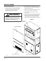
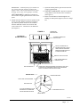
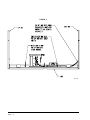
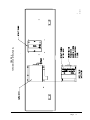
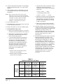
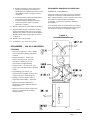
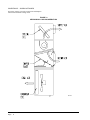
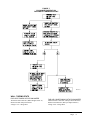
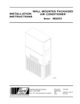
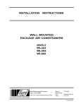
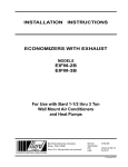
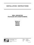
INSTALLATION INSTRUCTIONS
ECONOMIZERS WITH EXHAUST
Model
EIFM-5C
For Use with Bard 3-1/2 through 6 Ton
Wall Mount Air Conditioners
and Heat Pumps
Bard Manufacturing Company
Bryan, Ohio 43506
Since 1914...moving ahead just as planned.
Manual :
Supersedes:
File:
Date:
2100-447
Volume III Tab 19
12-14-04
© Copyright 2004
CONTENTS
GENERAL
General Information ................................................. 1
Unpacking ................................................................ 1
Description ............................................................... 1
INSTALLATION
Basic Installation ...................................................... 2
Economizer – WA, WL & WH Series ...................... 7
FIGURES
Figure 1
Figure 2
Figure 3
Figure 4
Figure 5
Figure 6
Figure 7
................................................................
................................................................
................................................................
................................................................
................................................................
................................................................
................................................................
2
3
4
5
7
8
9
TABLES
Table 1
Table 2
................................................................ 1
................................................................ 6
Manufactured under U.S. Patent number 5,301,744.
Other patents pending.
COPYRIGHT DECEMBER 2004
BARD MANUFACTURING COMPANY
BRYAN, OHIO USA 43506
GENERAL
GENERAL INFORMATION
DESCRIPTION
The economizer should only be installed by a trained
heating and air conditioning technician. These
instructions serve as a guide to the technician installing
the economizer package. They are not intended as a
step by step procedure with which the mechanically
inclined owner can install the package.
The EIFM-5 economizer is designed to be used with
Bard 3-1/2 through 5 ton wall mount series air
conditioners and heat pumps equipped with low ambient
fan cycling controls. They are electromechanical
economizer systems designed to provide “free” cooling
where the outdoor air temperature is cool enough to
provide the needed cooling without running the
compressor. When cooling is needed, the system
automatically takes advantage of cold outdoor air when
available and uses it for first stage cooling. This then
reduces the need to run the air conditioning compressor
providing lower operating costs and increasing the
service life of the equipment. If the outdoor air gets too
warm or humid to be helpful, the enthalpy control
detects the condition and automatically closes the
outdoor air and exhaust damper, opens the return air
damper and switches to the compressor operation. This
is all done automatically to achieve maximum savings
without attention from the user. See Figure 6 for a
block diagram of the economizer operation logic flow.
The unit is equipped with a full modulating type damper
motor which controls the damper position to a factory
set minimum supply air temperature.
The economizer housing is shipped in one carton which
contains the electrical harness, miscellaneous hardware
and installation instructions.
The economizer installation requires an additional two
stage cooling thermostat in place of the normal single
stage cooling thermostat. Also additional low voltage
wire will be required to transmit the second call (Y2) for
cool. (i.e., Use 6 conductor thermostat wire for an air
conditioning unit and 9 conductor thermostat wire for
heat pumps.) See Page 9 for required thermostats.
If using a Bard master controller, the MC91AE master
controller is designed specifically to control two (2)
redundant Bard wall mount units equipped with
economizers.
Any wall mount unit equipped with an economizer must
also have a low ambient control installed. This control
can be factory installed or field installed. If field
installed, use kit CMA-6 (air conditioner models) or
CMH-7 (heat pump models).
TABLE 1
(1)
MODEL
FOR USE WITH
FOLLOWING UNITS
UNPACKING
WA38
WL42
WH42
Upon receipt of the equipment be sure to compare the
model number found on the shipping label with the
accessory identification information on the orders and
shipping document to verify that the correct accessory
has been shipped.
WA42
WL48
WH48
WA48
WL60
WH60
WA49
WL70
SH38
Inspect the carton housing of each economizer as it is
received, and before signing the freight bill, verify that
all items have been received and that there is no visible
damage. Note any shortages or damage on all copies of
the freight bill. The receiving party must contact the
last carrier immediately, preferably in writing,
requesting inspection by the carrier’s agent. Concealed
damage not discovered until after loading must be
reported to the carrier within 15 days of its receipt.
EIFM-5C
WA60
SH43
WA61
SH49
WA70
SH61
WA72
(1) Low ambient control is required with economizer
for low temperature compressor operation.
EIFM models not suitable for use with hot gas bypass
models.
Manual 2100-447
Page
1
INSTALLATION
BASIC INSTALLATION
1. Unpack the economizer assembly which includes
the integral economizer with attached electrical
harness, mixed air thermistor, miscellaneous
hardware and installation instructions.
2. Remove and save the existing exterior blower
access and service access panels on the Bard wall
mount unit. (See Figure 1.)
3. Remove and save existing unit return air filter and
center screw in front grille. (See Figure 1.)
4. Remove and discard the exhaust cover plate.
(See Figure 1.)
WARNING
Open and lock unit disconnect switch before
installing this accessory to prevent injury or
death due to electrical shock or contact with
moving parts. Turn thermostat to off.
5. Install economizer by inserting the economizer into
the unit to the far left side clearing the right filter
bracket. Once the economizer is fully inserted,
slide the economizer to the right until it is tight
against the back of the control panel. (See Figure 2.)
FIGURE 1
THERMISTOR
LOCATION
BLOWER ACCESS PANEL
SCREW
SERVICE ACCESS PANEL
MIS-425
Manual 2100-447
Page
2
EXHAUST COVER PLATE
IMPORTANT: Position front lip of economizer on
top of front grille and condenser partition (See
Figure 2 inset.) This is important to ensure proper
drainage of any water entering damper assembly.
LEFT HAND UNITS – Slide the economizer to
the left until it is tight against the back of the corner
panel.
6. Mount mixed air thermistor to blower partition with
screws provided. Bracket with sensor installs on
top of blower partition and screws are installed
from the underside. Route wires as shown and
secure with wire tie. Connect wires to thermistor.
(See Figure 2.)
7. Open unit control panel to gain access to unit low
voltage terminal block.
8. FOR LEFT HAND UNITS – Reroute economizer
wiring harness to the left side of the economizer.
(See Figure 3.)
9. Route electrical harness leads through the 7/8"
bushing in control panel (Figure 2) into low voltage
box.
FIGURE 2
TOP VIEW OF
BLOWER PARTITION
THERMISTOR
PART #8602-043
THERMISTOR BRACKET
PART #113-264
INSTALL THERMISTOR TO
BLOWER PARTITION. ROUTE
WIRES FROM ECONOMIZER
BEHIND FILTER BRACKET FILL
& THROUGH WIRE TIE.
WIRE TIE TO SUCTION LINE
LOW VOLTAGE WIRES TO
TERMINAL STRIP
MIST ELIMINATOR
WHEN INSTALLING ECONOMIZER, POSITION SO THAT HOLE
IN FRONT LIP IS CENTERED OVER HOLE IN CONDENSER
GRILLE TO INSERT A SELF DRILLING SCREW
SIDE SECTION
THERMISTOR WIRES
RIGHT SIDE OF ECONOMIZER
SERVICE DOOR
LIP OF ECONOMIZER IS TO BE
BETWEEN THE CONDENSER
GRILLE AND SERVICE DOOR
CONDENSER PARTITION
FRONT GRILLE
MIS-423
Manual 2100-447
Page
3
FIGURE 3
MIS-1356
Manual 2100-447
Page
4
Manual 2100-447
Page
5
FIGURE 4
TOP VIEW OF CONTROL PANEL
MIS-350
MIS-350
10. Connect leads with fork terminal to corresponding
points on terminal strip. RE: C.Y.G. (See wiring
diagram.)
11. Wire nut leads with 5/8" stripped ends to Y1 and
Y2 leads from thermostat. See wiring diagram in
this manual.
NOTE: Wires referenced in note one on wiring
diagram are for special control application
only and are not normally used in conjunction
with other circuitry to open the damper
regardless of outside temperature and
humidity. Consult factory for details.
12. Close control panel cover
13. Reinstall the blower access panel at top of unit and
secure with sheet metal screws.
14. Replace filter and screws in front condenser grille.
15. ECONOMIZER CHECK OUT
A. Remove mist eliminator (Figure 2). Locate the
minimum position potentiometer (See Figure 4).
B. Energize the evaporator blower by switching
thermostat to the manual fan position with
heat/ cool in the OFF position.
C. Cycle the minimum position potentiometer
(factory set for 0% fresh air) 0 to full open.
(See Figure 3.) Throughout checkout
procedure observe operation of damper to
insure there is free, unobstructed operation
through the entire angle of damper travel.
Then adjust the damper minimum open
position to meet local codes or application
requirements. See example below.
EXAMPLE:
1. Measure return air temperature (RAT)
(assume 75°F for example).
2. Measure outdoor air temperature (OAT)
(assume 60°F for example).
3. Calculate the mixed air temperature (MAT)
which will result from the desired
combination of OAT (10 percent) and RAT
(90 percent).
.1 OAT + .9 RAT =
or substituting example values
.1 (60°F) + .9 (75°F) = 73.75°F
4. Adjust the minimum position potentiometer
knob until proper mixed air temperature as
calculated above is reached. Care should
be taken to insure thermometer is sensing
air that is well mixed.
5. Mark correct setting on dial of minimum
position potentiometer for future reference.
D. Adjust the enthalpy control to position A, B,
C and D to achieve the maximum combination
of temperature and humidity acceptable for the
installation as per Table 2 below. The
suggested setting is between A & B 70° DB
@ 55 percent RH. It is further recommended
to always set the control at C or above.)
(See Figure 4.)
E. Switch the thermostat fan control to automatic
and position the heat/cool switch to cool.
Adjust the thermostat temperature to engage
the first stage of cooling only (Y). This will
cause the dampers to modulate to achieve
mixed air temperature of 55° provided outside
air enthalpy is sufficiently low. If enthalpy is
too high for economizing, low enthalpy can be
simulated by temporarily removing and
jumping leads on terminal 2 and 3 of enthalpy
control together. This will also cause the
economizer damper to modulate away from
minimum position. (Be sure to properly
reconnect leads at end of checkout
procedure).
TABLE 2
ENTHALPY CONTROL SETTINGS
Dial
Setting
Enthalpy
Control
Setting
Manual 2100-447
Page
6
MAT
20% R H
50% R H
80% R H
A
80 deg .F
(26 deg. C)
73 deg. F
(23 deg. C)
66 deg. F
(19 deg.C)
B
76 deg. F
(24 deg. C)
70 deg. F
(21 deg. C)
63 deg. F
(17 deg. C)
C
74 deg. F
(23 deg. C)
66 deg. F
(19 deg. C)
59 deg. F
(15 deg. C)
D
71 deg. F
(21 deg. C)
63 deg. F
(17 deg. C)
54 deg. F
(12 deg. C)
F. Readjust temperature on the thermostat to
engage the second stage of cooling (Y2).
The damper motor should return to previously
set minimum position. Compressor motor
should start.
G. Switch thermostat to OFF fan and OFF heat/
cool positions to de-energize unit.
Economizer damper should return to full
closed (100 percent return air) position.
Checkout is complete.
16. Replace control access panel and mist eliminator.
17. Remove blank off plate or barometric fresh air
damper if installed on the service access panel.
Plug the four (4) holes used to mount the BOP or
BFAD with the plastic plugs supplied with the
economizer.
18. Replace service access panel.
ECONOMIZER SEQUENCE OF OPERATION
Condition A – Cool Outdoors
First stage cooling closes and powers the economizer
dampers to economizer mode and the indoor blower
starts. Mixed Air Sensor senses a mixture of return air
and outdoor air and modulates the dampers
accordingly. Compressor operation is inhibited.
(See Figure 5.)
If second stage closes on the thermostat, the dampers
return to the closed or minimum position setting and
the compressor starts for mechanical cooling.
FIGURE 5
ECONOMIZER OPERATION
19. Economizer is now ready for operation.
ECONOMIZER – WA, WL & WH SERIES
FEATURES
• One piece construction – easy to install
with no mechanical linkage adjustment
required.
• Exhaust air damper – built in with
positive closed position. Provides
exhaust air capability to prevent
pressurization of tight buildings.
• Actuator motor – 24 volt, power open,
spring return with built in torque limiting
switch.
• Proportioning type control – for
maximum “Free Cooling” economy and
comfort with up to 100% outside air.
• Enthalpy control to monitor outdoor
temperature and humidity – adjustable.
• Minimum position potentiometer –
adjustable to control minimum damper
blade position.
• Mixed air sensor to monitor outdoor and
return air to automatically modulate
damper position.
MIS-347
Manual 2100-447
Page
7
CONDITION B – WARM OUTDOORS
First stage cooling cycles the compressor and dampers
remain in mechanical cooling mode.
FIGURE 6
MECHANICAL COOLING OPERATION
MIS-348
Manual 2100-447
Page
8
FIGURE 7
ECONOMIZER OPERATION
FOR SINGLE COMPRESSOR UNIT
MIS-1351
WALL THERMOSTATS
FOR HEAT PUMPS WITH ECONOMIZER
Thermostat Part 8403-027 (White Rodgers IF92-71)
Electronic Heat Pump Thermostat
2 Stage Cool / 3 Stage Heat
FOR AIR CONDITIONING WITH ECONOMIZER
Thermostat Part 8403-021 (Honeywell T874D1934)
Subbase Part 8404-012 (Honeywell Q674A1001)
2 Stage Cool / 2 Stage Heat
Manual 2100-447
Page
9
Manual 2100-447
Page
10