1
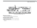
INSTRUCTION MANUAL
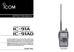
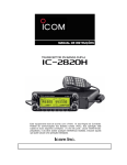
DUAL BAND FM TRANSCEIVER
iE2820
This device complies with Part 15 of the FCC Rules. Operation is subject to the following two conditions: (1) this device may not cause
harmful interference, and (2) this device must accept any interference
received, including interference that may cause undesired operation.
FOREWORD
IMPORTANT
Thank you for purchasing this Icom product. The IC-E2820
DUAL BAND FM TRANSCEIVER is designed and built with Icom’s
superior technology and craftsmanship. With proper care, this
product should provide you with years of trouble-free operation.
READ ALL INSTRUCTIONS carefully and completely
We want to take a couple of moments of your time to thank
you for making your IC-E2820 your radio of choice, and hope
you agree with Icom’s philosophy of “technology first.” Many
hours of research and development went into the design of
your IC-E2820.
before using the transceiver.
SAVE THIS INSTRUCTION MANUAL— This instruction manual contains important operating instructions for
the IC-E2820.
EXPLICIT DEFINITIONS
WORD
D FEATURES
❍ Diversity reception
❍ DV (Digital Voice) with GPS operation
(Optional UT-123 is required)
capabilities
DEFINITION
Personal injury, fire hazard or electric shock
R WARNING!
may occur.
CAUTION
NOTE
Equipment damage may occur.
Recommended for optimum use. No risk of
personal injury, fire or electric shock.
❍ V/V, U/U simultaneous receive capability
❍ Independent controls for both left and right
receivers
❍ Separate controller for flexible installation
❍ Remote control microphone included
i
Icom, Icom Inc. and the
logo are registered trademarks of Icom
Incorporated (Japan) in the United States, the United Kingdom, Germany, France, Spain, Russia and/or other countries.
All other products or brands are registered trademarks or trademarks
of their respective holders.
PRECAUTIONS
RWARNING RF EXPOSURE! This device emits Radio
Frequency (RF) energy. Extreme caution should be observed when
operating this device. If you have any questions regarding RF exposure and safety standards please refer to the Federal Communications Commission Office of Engineering and Technology’s report on
Evaluating Compliance with FCC Guidelines for Human Radio frequency Electromagnetic Fields (OET Bulletin 65).
NEVER let objects impede the operation of the cooling fan on the
rear panel.
DO NOT push the PTT when not actually desiring to transmit.
DO NOT allow children to play with any radio equipment containing a transmitter.
RWARNING! NEVER connect the transceiver to an AC outlet. This may pose a fire hazard or result in an electric shock.
During mobile operation, DO NOT operate the transceiver without running the vehicle’s engine. When the transceiver’s power is ON
and your vehicle’s engine is OFF, the vehicle’s battery will soon become exhausted.
RWARNING! NEVER operate the transceiver while driving a
AVOID using or placing the transceiver in direct sunlight or in
vehicle. Safe driving requires your full attention—anything less may
result in an accident.
NEVER connect the transceiver to a power source of more than
16 V DC. This will damage the transceiver.
NEVER connect the transceiver to a power source using reverse
areas with temperatures below –10°C or above +60°C.
BE CAREFUL! The transceiver will become hot when operating it continuously for long periods.
AVOID setting the transceiver in a place without adequate venti-
polarity. This will damage the transceiver.
lation. Heat dissipation may be affected, and the transceiver may be
damaged.
NEVER cut the DC power cable between the DC plug and fuse
AVOID the use of chemical agents such as benzine or alcohol
holder. If an incorrect connection is made after cutting, the transceiver
may be damaged.
NEVER expose the transceiver to rain, snow or any liquids. The
transceiver may be damaged.
when cleaning, as they can damage the transceiver’s surfaces.
USE Icom microphones only (supplied or optional). Other manufacturer’s microphones have different pin assignments and may damage the transceiver if attached.
NEVER operate or touch the transceiver with wet hands. This may
result in an electric shock or damage the transceiver.
NEVER place the transceiver where normal operation of the vehicle may be hindered or where it could cause bodily injury.
ii
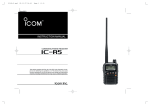
SUPPLIED ACCESSORIES
q
w
u
e
r
t
i
*HM-154 HAND MICROPHONE may be supplied with some versions.
†
Approx.
y
o
iii
q DC power cable (3 m) ………………………………………1
w Controller cable (10 cm†) ……………………………………1
e Separation cable (3.4 m†) …………………………………1
r Magnets with screws ………………………………………2
t Fuse (20 A) …………………………………………………1
y Microphone hanger …………………………………………1
u Microphone (HM-133)* ……………………………………1
i Mounting screws, nuts and washers …………………1 set
o Mobile mounting bracket …………………………………1
!0 Microphone connector plate with screw ……………1 set
!1 Remote controller bracket …………………………………1
!0
!1
TABLE OF CONTENTS
FOREWORD .................................................................................... i
IMPORTANT .................................................................................... i
EXPLICIT DEFINITIONS .................................................................. i
PRECAUTIONS ............................................................................... ii
SUPPLIED ACCESSORIES ........................................................... iii
TABLE OF CONTENTS .................................................................. iv
QUICK REFERENCE GUIDE .................................................. I–XIV
■ Installation ................................................................................ I
■ Your first contact ..................................................................... X
■ Repeater operation ............................................................... XII
■ Programming memory channels........................................... XIII
1 PANEL DESCRIPTION ........................................................ 1–14
■ Front panel— controller .......................................................... 1
■ Function display ...................................................................... 3
■ Function guide indications ...................................................... 7
■ Main unit ................................................................................. 9
■ Microphone (HM-133) ........................................................... 11
■ Microphone keypad ............................................................... 12
■ Optional microphones (HM-154)............................................ 14
2 SETTING A FREQUENCY ................................................. 15–19
■ Preparation ........................................................................... 15
■ Using the tuning dial ............................................................. 17
■ Using the [Y]/[Z] keys .......................................................... 17
■ Using the keypad .................................................................. 17
■ Tuning step selection ............................................................ 18
■ Lock functions ....................................................................... 19
3 BASIC OPERATION .......................................................... 20–28
■ Receiving .............................................................................. 20
■ Transmitting .......................................................................... 20
■ Selecting output power ......................................................... 21
■ Operating mode selection ..................................................... 21
■ Squelch attenuator ................................................................ 22
■ V/V, U/U simultaneous receive (Para-watch) ........................ 23
■ Sub-band mute/busy beep .................................................... 24
■ Monitor function .................................................................... 24
■ Single band operation ........................................................... 25
■ One-touch PTT function ........................................................ 26
■ Audio mute function .............................................................. 27
■ Band scope ........................................................................... 27
4 REPEATER OPERATION .................................................. 29–34
■ General ................................................................................. 29
■ Accessing a repeater ............................................................ 30
■ Subaudible tones .................................................................. 32
■ Offset frequency .................................................................... 34
5 DV MODE OPERATION (Optional UT-123 is required) ..... 35–59
■ Digital mode operation .......................................................... 35
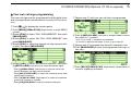
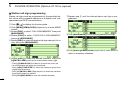
■ Call sign programming .......................................................... 35
■ Digital voice mode operation ................................................. 38
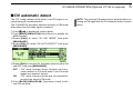
■ DV automatic detect ............................................................. 40
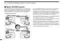
■ About D-STAR system .......................................................... 41
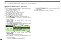
■ Digital repeater operation ...................................................... 42
■ Received call sign ................................................................. 47
■ Copying the call sign ............................................................. 49
1
2
3
4
5
6
7
8
9
10
11
12
13
14
15
16
17
18
19
iv
TABLE OF CONTENTS
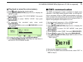
■ Break-in communication ....................................................... 51
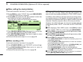
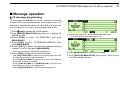
■ Message operation ............................................................... 52
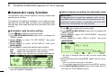
■ Automatic reply function ........................................................ 55
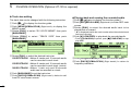
■ EMR communication ............................................................. 56
■ Low-speed data communication ........................................... 57
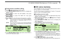
■ DV voice memory .................................................................. 58
8 SCAN OPERATION ........................................................... 73–78
■ Scan types ............................................................................ 73
■ Scan start/stop ...................................................................... 74
■ Scan edges programming ..................................................... 75
■ Scan resume condition ......................................................... 77
■ Skip channel setting .............................................................. 78
6 MEMORY MODE OPERATION .......................................... 60–70
■ General description ............................................................... 60
■ Memory channel selection .................................................... 60
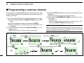
■ Programming a memory channel .......................................... 61
■ Memory bank selection ......................................................... 63
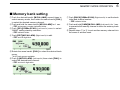
■ Memory bank setting ............................................................. 64
■ Programming memory/bank/scan name ............................... 65
■ Copying memory contents .................................................... 67
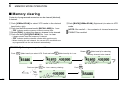
■ Memory clearing ................................................................... 69
■ Erasing/transferring bank contents ....................................... 70
9 PRIORITY WATCH ............................................................. 79–80
■ Priority watch types ............................................................... 79
■ Priority watch operation ........................................................ 80
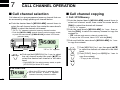
7 CALL CHANNEL OPERATION ......................................... 71–72
■ Call channel selection ........................................................... 71
■ Call channel copying ............................................................. 71
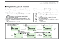
■ Programming a call channel ................................................. 72
v
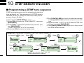
10 DTMF MEMORY ENCODER .............................................. 81–84
■ Programming a DTMF tone sequence .................................. 81
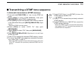
■ Transmitting a DTMF tone sequence .................................... 82
■ DTMF speed ......................................................................... 84
11 TONE SQUELCH AND POCKET BEEP ............................ 85–90
■ Tone/DTCS squelch beep operation ..................................... 85
■ DTCS polarity setting ............................................................ 88
■ Tone scan .............................................................................. 89
■ Digital call sign/digital code squelch ..................................... 90
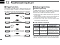
12 PAGER/CODE SQUELCH ................................................. 91–94
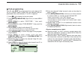
■ Pager function ....................................................................... 91
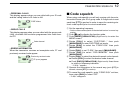
■ Code programming ............................................................... 91
■ Pager operation .................................................................... 93
■ Code squelch ........................................................................ 94
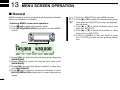
13 MENU SCREEN OPERATION ......................................... 95–112
■ General ................................................................................. 95
■ Menu list ................................................................................ 96
■ Item list .................................................................................. 96
■ SET MODE items .................................................................. 99
■ DV SET MODE items .......................................................... 101
■ SCAN items ........................................................................ 103
■ DUP/TONE items................................................................. 104
■ DISPLAY items ................................................................... 105
■ SOUND items ..................................................................... 107
■ DV GPS items ..................................................................... 108
■ PACKET items .................................................................... 109
■ GPS SET MODE items ....................................................... 109
■ GPS-A SET MODE items .................................................... 111
14 OTHER FUNCTIONS ..................................................... 113–120
■ Microphone keys ................................................................. 113
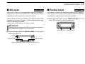
■ All reset ............................................................................... 114
■ Partial reset ......................................................................... 114
■ Data cloning ........................................................................ 115
■ Auto power OFF .................................................................. 116
■ Time-out timer ..................................................................... 116
■ Packet operation ................................................................. 117
15 GPS/GPS-A OPERATION .............................................. 121–128
■ GPS operation .................................................................... 121
■ GPS-A operation ................................................................. 128
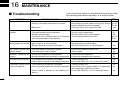
16 MAINTENANCE ............................................................. 129–131
■ Troubleshooting .................................................................. 129
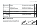
■ Fuse replacement ............................................................... 130
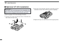
■ Optional UT-123 installation ................................................ 131
17 SPECIFICATIONS AND OPTIONS ................................ 132–134
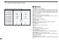
■ Specifications ...................................................................... 132
■ Options ................................................................................ 133
18 ABOUT CE ..................................................................... 135–136
1
2
3
4
5
6
7
8
9
10
11
12
13
14
15
16
17
18
19
vi
QUICK REFERENCE GUIDE
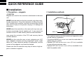
■ Installation
D Precaution— magnets
D Installation methods
RCAUTION
Magnets are used for the controller’s attachment to the main
unit.
Controller
NEVER hold the whole unit by the controller only when carrying the transceiver. Carry the transceiver holding the main
unit. If held by the controller, the main unit may drop off and
may result in injury to the person carrying it or damage the
transceiver.
NEVER attach the controller on the main unit’s top cover, particularly around the internal speaker grill. It may cause the
contents of the CPU and memory device could be deleted.
may cause the contents of the CPU and memory device
could be deleted.
NEVER put the controller near a clock, television set (CRT
type), magnetic compass and any magnetic/IC cards, credit
cards, etc. It may cause the product to malfunction, and the
content of the magnetic card could be deleted.
Please note that the controller may drop off when a high impact or vibration is applied.
I
Main unit
• The supplied remote controller bracket and separation cable
can be used for installation.
• The optional MB-65 MOUNTING BASE must be used when installing into your vehicle.
• Optional OPC-440 MICROPHONE CABLE (5.0 m) is available
to extend the microphone cable.
• Optional OPC-441 SPEAKER CABLE (5.0 m) is available to extend the speaker cable.
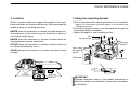
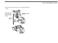
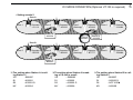
D Location
D Using the mounting bracket
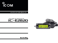
Select a location which can support the weight of the transceiver and does not interfere with driving. We recommend the
locations shown in the diagram below.
qDrill 4 holes where the mounting bracket is to be installed.
NEVER place the transceiver or remote controller where normal operation of the vehicle may be hindered or where it
could cause bodily injury.
NEVER place the transceiver or remote controller where air
bag deployment may be obstructed.
DO NOT place the transceiver or remote controller where hot
or cold air blows directly onto it.
AVOID placing the transceiver or remote controller in direct
sunlight.
• Approx. 5.5–6 mm when using nuts; approx. 2–3 mm when using
self-tapping screws.
wInsert the supplied screws, nuts and washers through the
mounting bracket and tighten.
eAdjust the angle for your suitable position.
Nut
Spring washer
Mounting
bracket
When using
self-tapping
screws
Flat washer
Main unit
Controller
Quick reference guide
QUICK REFERENCE GUIDE
Mounting nut
25˚
Main unit
Main unit
IMPORTANT!
Detailed installation notes for Icom mobile transceivers to
fitted into vehicles are available. Contact your Icom dealer
or distributor.
II
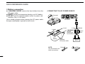
QUICK REFERENCE GUIDE
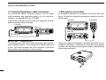
D Controller/Separation cable connection
D Microphone connection
Two connection cables, controller cable (10 cm) for single
body installation and separation cable (3.4 m) for remote installation, are supplied with the IC-E2820.
A microphone connector is available on the main unit front
panel. Connect the supplied microphone connector as illustrated below.
Connect the controller and the main unit using with the supplied connection cable as follows.
Controller
Microphone
Controller
Main unit
Main unit
4-pin connector
6-pin connector
IMPORTANT!— number of pin
The connectors on the ends of the connection cable have different numbers of pins - one end has 6 pins and the other end
4 pins. You should connect the 6-pin connector to the main
unit, and the 4-pin connector to the controller.
III
Attach the supplied microphone connector plate after the microphone connection, otherwise the controller will separate
from the mail unit when the microphone cable is pulled during
single body installation.
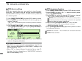
D Optional GPS antenna connection
D Important notes when using GPS receiver
When the optional UT-123 is installed, the GPS antenna supplied with the UT-123 can be connected.
Connect the GPS antenna as below.
• The GPS antenna is not weather-proof construction, therefore, NEVER install the antenna in outdoor.
GPS antenna
to [GPS ANT]
GPS antenna cable length: approx. 5 m (16.4 ft)
Mount the GPS antenna onto a convenient flat surface. The
GPS antenna includes magnet mount base, therefore, the antenna can be mounted onto a metal roof/wall, etc.
NOTE
When the GPS antenna is connected, only remote installation is allowed.
• Please do not install the GPS antenna close the TX antenna. The transmit signal may cause GPS receiver mulfunction.
• The GPS signal cannot pass through the metal object.
When installing GPS antenna inside a vehicle, we recommend to mount under the front or rear glass such as on the
dashboard, etc. Please avoid the areas shown in the following:
1. Do not mount where it will block the driver’s view.
2. Do not mount where the air bags could deploy.
Quick reference guide
QUICK REFERENCE GUIDE
• The Global Positioning System (GPS) is built and operated
by the US Defence Department. The Department is responsible for accuracy and maintenance of the system. Any
changes that the Department makes may affect the accuracy and function of the GPS system.
• When GPS receiver is activated, please do not cover the
GPS antenna with any object.
• The GPS receiver may not work if used in the following locations:
1. Tunnels or high-rise buldings
2. Underground parking lot
3. Under a bridge or viaduct
4. In remote forested areas
5. Under bad weather condition (rainy or cloudy day)
IV
QUICK REFERENCE GUIDE
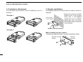
D Controller’s attachment
D Remote installation
You can attach the controller of the IC-E2820 by one of 2
methods.
The supplied remote controller bracket is used for remote installation.
• Attach the remote controller
bracket onto a flat surface
using with 4 self-tapping
These screws
screws (2.6 mm(d)), or doubleare not supplied.
sticky tape, etc., as at left,
then attach remote controller
to the bracket.
• Example 1
Remote controller bracket
• Example 2
When installing into your vehicle
qAttach the supplied remote controller bracket as below.
Remote controller
bracket
V
Remote
controller
wAttach the remote controller on to the optional MB-65 as
below.
Adjust the viewing angle for
maximum visibility of the function
display.
Remote controller
bracket
Quick reference guide
QUICK REFERENCE GUIDE
Optional
MB-65
VI
QUICK REFERENCE GUIDE
D Battery connection
➥ RWARNING NEVER remove the fuse holders from the
DC power cable.
➥ NEVER connect the transceiver directly to a 24 V battery.
➥ DO NOT use the cigarette lighter socket for power connections. (See p. 10 for details)
Use a rubber grommet when passing the DC power cable
through a metal plate to prevent a short circuit.
• CONNECTING TO A DC POWER SOURCE
Grommet
IC-E2820
_ black
⊕ red
+ red
RWARNING!
NEVER
remove the
fuse holders.
12 V
battery
Supplied
DC power cable
Crimp
NOTE:
Use terminals for the
cable connections.
VII
− black
Fuses
20 A
12 V
Solder
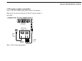
D DC power supply connection
Use a 13.8 V DC power supply with at least 15 A capacity.
Make sure the ground terminal of the DC power supply is
grounded.
• CONNECTING TO A DC POWER SUPPLY
Quick reference guide
QUICK REFERENCE GUIDE
IC-E2820
DC power
supply 13.8 V
to an
AC
outlet
−
− black
⊕ red
⊕
Fuses
20 A
See p. 130 for fuse replacement.
VIII
QUICK REFERENCE GUIDE
D Antenna installation
• Antenna location
To obtain maximum performance from the transceiver, select
a high-quality antenna and mount it in a good location. It is
not necessary to use radials on a magnetic mount (“mag
mount”) antenna.
Roof-mount antenna
(Drill a hole or use a magnetic mount.)
Trunk-mount
antenna
• Antenna connector
The antenna uses a PL-259 connector.
• PL-259 CONNECTOR
30 mm
Coupling ring
10 mm (soft solder)
10 mm Soft
solder
Gutter-mount antenna
1–2 mm
solder solder
q Slide the coupling ring
down. Strip the cable
jacket and soft solder.
w Strip the cable as shown
at left. Tin the center conductor.
e Slide the connector body
on and solder it.
r Screw the coupling ring
onto the connector body.
NOTE: There are many publications covering proper antennas and their installation. Check with your local dealer
for more information and recommendations.
To antenna
for Tx/Rx
IX
To antenna
for diversity
reception
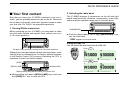
■ Your first contact
2. Selecting the main band
Now that you have your IC-E2820 installed in your car or
shack, you are probably anxious to get on the air. We would
like to take you through a few basic operation steps to make
your first time “On The Air” an enjoyable experience.
1. Turning ON the transceiver
Before powering up your IC-E2820, you may want to make
sure the audio volume and squelch level controls are set in
9–10 o’clock positions.
The IC-E2820 displays 2 frequencies on the left and right
bands simultaneously. However, transmission, some keys
and microphone operation apply only to the main band.
[MAIN•BAND]
Quick reference guide
QUICK REFERENCE GUIDE
➥ Push the desired band’s (left or right) [MAIN•BAND] to select the main band.
• “Q” appears for the main band.
Using the HM-133
You can select the main band from the HM-133.
Set both [VOL] and [SQL] controls to 9–10 o’clock positions.
Push
Although you have purchased a brand new transceiver, some
settings may be changed from the factory defaults because
of the Quality Control (QC) process. Resetting the CPU is
necessary to start from factory default.
Push
[PWR]
[M/CALL•MW]
again
[M/CALL•MW]
While pushing both [M/CALL•MW], turn power ON.
➥ While pushing both band’s [M/CALL•MW] keys, push and
hold [PWR] for 1 sec. to reset the CPU.
X
QUICK REFERENCE GUIDE
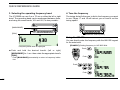
3. Selecting the operating frequency band
4. Tune the frequency
The IC-E2820 can use 2 m or 70 cm on either the left or right
band. The operating band can be exchanged between them,
and using the same bands, V/V and U/U, is also possible..
The tuning dial will allow you to dial in the frequency you want
to use. Pages 17 and 18 will instruct you on how to set the
tuning speed.
[MAIN•BAND]
[DIAL]
Rotate the desired [DIAL].
Using the HM-133
You can directly enter the frequency with the HM-133 keypad
for the main band.
[EXAMPLE]: Setting frequency to 145.3625 MHz.
Frequency band initial is displayed.
Push
➥ Push and hold the desired band’s (left or right)
[MAIN•BAND] for 1 sec. then rotate the appropriate band’s
[DIAL].
Push
• Push [MAIN•BAND] momentarily to return to frequency indication.
Push
Push
XI
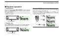
■ Repeater operation
1. Setting duplex
Using the HM-133
Push the desired band’s [MAIN•BAND] to select the main
band. Push [DUP•MONI] once or twice to select minus duplex or plus duplex.
Plus or minus duplex selection and the repeater tone setting
can be made easily via the HM-133.
Push [DUP– 7(TONE)] for minus duplex; [DUP+ 8(TSQLS)]
for plus duplex selection, push [FUNC] then [DUP– 7(TONE)]
to turn the repeater tone ON.
• The USA version has an auto repeater function, therefore, setting
duplex is not required.
Push
Quick reference guide
QUICK REFERENCE GUIDE
Push
Push [DUP•MONI].
2. Repeater tone
Push [TONE•DTMF] several times until “TONE” appears, if
the repeater requires a subaudible tone to be accessed.
Push
, then
Push [TONE•DTMF].
XII
QUICK REFERENCE GUIDE
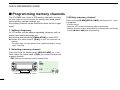
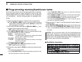
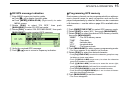
■ Programming memory channels
The IC-E2820 has a total of 522 memory channels (including
20 scan edges and 2 call channels) for storing often used operating frequency, repeater settings, etc.
Any memory channel can be recalled on either the left or right
band.
1. Setting a frequency
In VFO mode, set the desired operating frequency with repeater, tone and tuning steps, etc.
➥ Push the desired band’s [V/MHz•SCAN] to select VFO.
➥ Rotate the same band’s [DIAL] to set the desired frequency.
• Set other data, such as repeater tone, duplex information, tuning
step), if desired.
2. Selecting a memory channel
Push and hold the same band’s [M/CALL•MW] for 1 sec.,
then rotate the same band’s [DIAL] to select the desired
memory channel.
• “X” indicator and memory channel number blink.
Push [M/CALL•MW] for 1 sec.
XIII
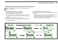
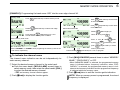
3. Writing a memory channel
Push and hold [S.MW](M/CALL•MW) (Left band’s) for 1 sec.
to program.
• 3 beeps sound
• Return to VFO mode automatically after programming.
• Memory channel number automatically increases when continuing
to push [M/CALL•MW] after programming.
Using the HM-133
q Push [MR/CALL] to select memory mode.
wPush [ENT C(T-OFF)] first, then enter the desired memory
channel via the keypad.
ePush [VFO/LOCK] to select VFO mode, then set the desired operating frequency, including offset direction, tone
settings, etc.
➥ Push [VFO/LOCK] to select VFO.
➥ Push [ENT C(T-OFF)] first, then enter the desired operating frequency via the keypad.
Quick reference guide
QUICK REFERENCE GUIDE
• Set other data, such as repeater tone, duplex information, tuning step, if necessary.
rPush [FUNC] then push and hold [CLR A(MW)] for 1 sec.
to program.
Push
,
then
• 3 beeps sound
• Memory channel number automatically increases when continuing to push [CLR A(MW)] after programming.
XIV
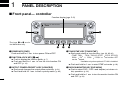
1
PANEL DESCRIPTION
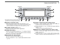
■ Front panel— controller
Function display (pgs. 3–8)
iE2820
DUAL BAND TRANSCEIVER
q
w
D
N
N
BAN
BAN
D
MA
*The keys w to t are for
the MAIN band only.
I
MA
V/MHz
SCAN
M/CALL
MW
DUP
MONI
TONE
DTMF
LOW
PRIO
t
r
e
q POWER KEY [PWR]
Push and hold for 1 sec. to turn power ON and OFF.
w FUNCTION•LOCK KEY [F• ]
➥ Push to display the function guide. (p. 7)
➥ Push and hold for 1 sec. to turn the lock function ON
and OFF. (p. 19)
e OUTPUT POWER•PRIORITY KEY [LOW•PRIO]
➥ Each push changes the output power selection. (p. 21)
➥ Push and hold for 1 sec. to start a priority watch. (p. 80)
1
M/CALL
MW
I
V/MHz
SCAN
r TONE•DTMF KEY [TONE•DTMF]
➥ Each push selects a tone function. (pgs. 30, 85, 90)
• TONE, TSQL , TSQL, TSQL-R, DTCS , DTCS, DTCS-R,
DSQL ,* DSQL,* CSQL ,* CSQL* or tone function OFF
can be selected.
*Available only when optional UT-123 is installed.
➥ Push and hold for 1 sec. to enter DTMF set mode. (p. 82)
t DUPLEX•MONITOR KEY [DUP•MONI]
➥ Push to select DUP–, DUP+ and simplex (no indicator visible) operation. (p. 30)
➥ Push and hold for 1 sec. to turn the monitor function ON
and OFF. (p. 24)
PANEL DESCRIPTION
Left band
Right band
y
y
iE2820
DUAL BAND TRANSCEIVER
u
N
N
BAN
BAN
D
*The same controls for both the left and
right bands are arranged symmetrically.
u
D
i
MA
MA
o
V/MHz
SCAN
M/CALL
MW
!0
!1
y SQUELCH CONTROL [SQL]
Varies the squelch level for left and right band. (p. 20)
• The RF attenuator activates and increases the attenuation when
rotated clockwise at and beyond the center position. (p. 22)
u VOLUME CONTROL [VOL] (p. 20)
Adjusts the audio level for left or right band.
i TUNING DIAL [DIAL]
Selects the operating frequency (p. 17), memory channel
(p. 60), the setting of the set mode item and the scanning
direction (p. 75) for left or right band.
o MAIN•BAND KEY [MAIN•BAND]
➥ Push to select the main band. (p. 15)
➥ Push and hold for 1 sec. to enter band selection mode.
(p. 15)
1
DUP
MONI
TONE
DTMF
LOW
PRIO
M/CALL
MW
V/MHz
SCAN
!1
!0
I
i
o
!0 VFO/MHz TUNING•SCAN KEY [V/MHz•SCAN]
➥ Push to select between VFO mode and 1 MHz (or
10 MHz for some versions) tuning. (p. 17)
➥ Push and hold for 1 sec. to enter scan type selection
mode. (p. 74)
• Cancels a scan when pushed during scan.
!1 MEMORY/CALL•MEMORY WRITE KEY [M/CALL•MW]
➥ Push to select and toggle memory and call channel
modes. (pgs. 60, 71)
➥ Push and hold for 1 sec. to enter select memory write
mode for memory channel programming. (pgs. 61, 72, 75)
1
2
3
4
5
6
7
8
9
10
11
12
13
14
15
16
17
18
19
2
1
PANEL DESCRIPTION
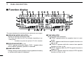
■ Function display
q
w e
r
t
y q
u q
w e
r
i
o
!0
@0
!1
!1
!2
!7
!9
!6
!5 !4 !2 !3
!8
!7 !6
!5 !4
!3
*The same indications for both the left and right bands are arranged.
q OPERATING MODE INDICATOR (p. 21)
Shows the selected operating mode.
• FM, FM-N, AM, AM-N and DV* are available, depending on operating band.
*Available only when the optional UT-123 is installed.
w DUPLEX INDICATORS (p. 30)
“DUP+” appears when plus duplex, “DUP –” appears when
minus duplex (repeater) operation is selected.
e NAME INDICATOR
During memory mode operation, the programmed memory
or memory bank name is displayed.
3
r TONE INDICATOR
➥ During FM mode operation:
● “TONE” appears while the repeater tone is in use.
(p. 30)
● “TSQL” appears while the tone squelch function is in
use. (p. 85)
● “TSQL-R” appears while the reverse tone squelch
function is in use. (p. 86)
● “DTCS” appears while the DTCS squelch function is
in use. (p. 85)
● “DTCS-R” appears while the reverse DTCS squelch
function is in use. (p. 86)
PANEL DESCRIPTION
➥ During DV* (Digital) mode operation:
● “DSQL” appears while the digital call sign squelch
function is in use. (p. 90)
● “CSQL” appears while the digital code squelch function is in use. (p. 90)
➥ “ ” appears with the “TSQL,” “DTCS,” “DSQL”* or “C
SQL”* indicator while the pocket beep function is in use.
(pgs. 85, 90)
*Available only when the optional UT-123 is installed.
t EMR MODE INDICATOR (p. 56)
➥ “EMR” appears when the EMR mode* operation is in
use.
➥ “L” appears when packet loss occurs during the lowspeed data communication*.
*Available only when the optional UT-123 is installed.
y GPS INDICATOR (p. 122)
➥ Appears while GPS function* is in use and GPS signal
is received..
➥ Blinks when GPS signal cannot be received.
*Available only when the optional UT-123 is installed.
u DTMF INDICATOR (p. 82)
Appears while automatic DTMF transmission is in use.
i BREAK-IN INDICATOR (p. 51)
Appears when the break-in* operation is in use.
*Available only when the optional UT-123 is installed.
1
o AUTO POWER OFF INDICATOR (p. 118)
Appears when the auto power OFF function is in use.
!0 KEY LOCK INDICATOR (p. 19)
Appears when the key lock function is activated.
!1 FREQUENCY READOUT
Shows the operating frequency, set mode contents, etc.
• Frequency decimal point blinks while scanning. (p. 74)
!2 PRIORITY INDICATOR (p. 80)
Appears while priority watch is activated, blinks while priority watch is paused.
!3 MEMORY CHANNEL NUMBER INDICATORS
➥ Shows the selected memory channel number. (p. 60)
➥ Shows the selected bank initial. (p. 63)
➥ “C” appears when the call channel is selected. (p. 71)
!4 SKIP INDICATOR (p. 78)
➥ “≈” appears when the displayed memory channel is
specified as a skip channel.
➥ “P≈” appears when the displayed frequency is specified
as a program skip frequency.
!5 MEMORY INDICATOR (p. 60)
Appears when memory mode is selected.
1
2
3
4
5
6
7
8
9
10
11
12
13
14
15
16
17
18
19
4
1
PANEL DESCRIPTION
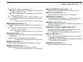
■ Function display— continued
q
w e
r
t
y q
u q
w e
r
i
o
!0
@0
!1
!1
!2
!7
!9
!6
!5 !4 !2 !3
!8
!7 !6
!5 !4
!3
*The same indications for both the left and right bands are arranged.
!6 S/RF INDICATORS
➥ Shows the relative signal strength while receiving signals. (p. 20)
➥ Shows the output power level while transmitting. (p. 21)
!7 OUTPUT POWER INDICATORS
“LOW” appears when low output power; “MID” appears
when middle output power, “HI” appears when high output
power is selected.
!8 BUSY INDICATOR
➥ Appears when a signal is being received or the squelch
is open. (p. 20)
➥ Blinks while the monitor function is activated. (p. 24)
5
!9 AUDIO MUTE INDICATOR
Appears when the audio mute (p. 27) or sub-band mute
(p. 24) function is in use.
@0 MAIN INDICATOR (p. 15)
Indicates the main band for transmit and function control.
PANEL DESCRIPTION
@2
@3
@4
Function guide indications (pgs. 7, 8)
@2 FREQUENCY MARKER (p. 27)
Gap shows the selected frequency in the band scope.
@3 CENTER FREQUENCY MARKER
Dotted line shows the center frequency of the band scope.
@4 BAND SCOPE INDICATOR
When the band scope function is in use, shows the band
conditions.
1
1
2
3
4
5
6
7
8
9
10
11
12
13
14
15
16
17
18
19
6
1
PANEL DESCRIPTION
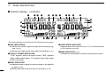
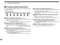
■ Function guide indications
The function guide indicators allow you to simply using a wide
variety of functions.
D Function guide
q
w
r SCAN SKIP KEY [SKIP](TONE•DTMF) (p. 78)
In memory mode, push to select the scan skip condition
for the selected memory channel.
• “≈” appears when memory skip, “P≈” appears when program
skip selection.
e
r
t
y
u
tMEMORY NAME INDICATION KEY [M.N](LOW•PRIO)
(p. 67)
Push to select the memory name indication.
q MODE KEY [MODE](V/MHz•SCAN) (p. 21)
Push to select an operating mode from FM, FM-N, AM,
AM-N and DV* in main band.
*Available only when the optional UT-123 is installed.
w TUNING STEP KEY [TS](M/CALL•MW) (p. 18)
Push to display the tuning step selection mode.
• 5.0,* 6.25,* 10, 12.5, 15,* 20, 25, 30 and 50 kHz steps are available.
*Not selectable in 900 MHz band.
e BAND SCOPE KEY [SCP](DUP•MONI) (p. 28)
➥ Push to display the simple band scope and make a single sweep of the band.
➥ Push and hold for 1 sec. to display the simple band
scope and sweep continuously.
• Push [SCP](DUP•MONI) momentarily to cancel the sweep.
7
• Memory name, frequency and OFF selections are available.
y SINGLE WATCH KEY [SNGL](M/CALL•MW) (p. 25)
Push to select the single band operation mode.
• Push [DUAL](M/CALL•MW)(for right band) to select the dualwatch mode.
u MENU MODE KEY [MENU](V/MHz•SCAN) (p. 96)
Push to select the MENU screen indication.
PANEL DESCRIPTION
D Function guide 2
D Function guide 3
The function guide 2 indicators appear only when the optional UT-123 is installed and DV mode is selected.
i
o
!0
1
!1
!2
!3
u
i CALL SIGN SELECT KEY [CS](V/MHz•SCAN) (p. 38)
Push to display the call sign selection screen.
oRECEIVED CALL SIGN RECORD KEY
[CD](M/CALL•MW) (p. 47)
Push to display the received call sign record screen.
!0 CQ KEY [CQ](DUP•MONI) (p. 39)
Push to set “CQCQCQ” as the station call sign for the call.
!1 CALL SIGN SET KEY [R>CS](TONE•DTMF) (p. 47)
Push to copy and set the previously received station call
sign as the station call sign for making a call.
!2 DV MESSAGE KEY [MSG](LOW•PRIO) (p. 53)
Push to display the DV message screen.
!3 VOICE MEMORY KEY [REC](V/MHz•SCAN) (p. 58)
Push to display the DV voice memory record screen.
The function guide 3 indications appear only when the optional UT-123 is installed and GPS function is set to ON.
!4
!5
!6
!7
!8
u
!4 DATA KEY [DATA](V/MHz•SCAN) (p. 123)
Push to toggle GPS data communication ON and OFF.
• “G•D” appears when the GPS data from GPS receiver is selected.
!5 POSITION INFORMATION KEY [POSI](M/CALL•MW)
(p. 123)
Push to toggle your own position information, target station information screen and frequency indication.
!6 GPS DATA STORE KEY [G-WR](DUP•MONI) (p. 123)
Push and hold for 1 sec. to store your own current position
information.
!7 GPS MEMORY RECALL KEY [GMR](TONE•DTMF) (p. 126)
Push to cause the GPS memory screen to display the
stored position information.
!8 RECEIVED POSITION DATA STORE KEY
[R-WR](LOW•PRIO) (p. 125)
Push and hold for 1 sec. to store the received position information.
1
2
3
4
5
6
7
8
9
10
11
12
13
14
15
16
17
18
19
8
1
PANEL DESCRIPTION
■ Main unit
q
we
r
t
e GPS ANTENNA CONNECTOR [GPS ANT] (p. IV)
When the optional digital unit, UT-123, is installed, connects the GPS antenna supplied with the optional UT-123.
rPACKET JACK [PACKET] (pgs. 118, 119)
Connects a TNC (Terminal Node Controller), etc. for data
communications. The transceiver can support 1200/9600
bps packet communication (AFSK/GMSK).
t MICROPHONE CONNECTOR [MIC] (p. III)
Connects the supplied or an optional microphone.
y
u
i
o !0
!1
i
q CONTROLLER CONNECTOR [CONTROLLER] (p. III)
Connects the controller unit with the supplied controller or
separation cable.
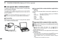
w DATA JACK [DATA] (p. 57)
Connect to a PC via the optional data communication cable
OPC-1529R for data cloning with the optional cloning software, CS-2820, or low-speed data communication in DV*
mode operation.
*Available only when the optional UT-123 is installed.
9
q
q +8 V DC output (Max. 10 mA)
w Channel up/down
e 8 V control IN
r PTT
t GND (microphone ground)
y MIC (microphone input)
u GND
i Data IN
y ANTENNA CONNECTOR [ANT1 TX/RX] (p. IX)
Connects a 50 Ω antenna with a PL-259 connector and a
50 Ω coaxial cable for transmission and reception.
u COOLING FAN
Rotates while transmitting.
Also rotates while receiving depending on the setting in set
mode. (p. 99)
PANEL DESCRIPTION
i ANTENNA CONNECTOR [ANT2 RX] (p. IX)
Connects a 50 Ω antenna with a PL-259 connector and a
50 Ω coaxial cable for diversity reception.
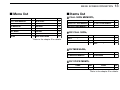
o EXTERNAL SPEAKER JACK 1 [SP-1]
Connects an 8 Ω speaker. Outputs audio from both left and
right bands when no external speaker is connected to [SP2]. See the table at right for details.
ANTENNA INFORMATION
For radio communications, the antenna is of critical importance, to maximize your output power and receiver sensitivity. The transceiver accepts a 50 Ω antenna and a
Voltage Standing Wave Ratio (VSWR) of 1.5:1 or less. High
SWR values not only may damage the transceiver but also
lead to TVI or BCI problems.
• Audio output power is more than 2.4 W.
!0 EXTERNAL SPEAKER JACK 2 [SP-2]
Connects an 8 Ω speaker. Outputs right band’s audio only.
• Audio output power is more than 2.4 W.
!1 POWER RECEPTACLE [DC13.8V]
Accepts 13.8 V DC ±15% with the supplied DC power
cable.
NOTE: DO NOT use a cigarette lighter socket as a
power source when operating in a vehicle. The plug
may cause voltage drops and ignition noise may be superimposed onto transmit or receive audio.
1
• Speaker information
Connected
speaker
No external
speakers
[SP-1] only
Left band audio
Right band audio
Internal speaker (mixed audio)
External speaker (mixed audio)
[SP-2] only
Internal speaker
External speaker
2 external
speakers
External speaker via
[SP-1]
External speaker via
[SP-2]
1
2
3
4
5
6
7
8
9
10
11
12
13
14
15
16
17
18
19
10
1
PANEL DESCRIPTION
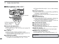
■ Microphone (HM-133*)
q
w
e
r
r ACTIVITY INDICATOR
➥ Lights red while any key, except [FUNC] and [DTMF-S],
is pushed, or while transmitting.
➥ Lights green while the one-touch PTT function is in use.
Mic element
t KEYPAD (pgs. 12, 13)
t
*A different microphone
may be supplied depending on version.
q VFO/LOCK KEY [VFO/LOCK]
➥ Push to select VFO mode. (p. 16)
➥ Push and hold for 1 sec. to turn the lock function ON
and OFF. (p. 19)
w PTT SWITCH
➥ Push and hold to transmit; release to receive.
➥ Switches between transmitting and receiving while the
one-touch PTT function is in use. (p. 26)
e UP/DOWN KEYS [Y]/[Z]
➥ Push either key to change operating frequency, memory channel, set mode setting, etc. (pgs. 17, 60, 96)
11
➥ Push and hold either key for 1 sec. to start scanning.
!1
!0
o
i
u
y
(p. 74)
y FUNCTION INDICATOR
➥ Lights orange while [FUNC] is activated—indicates the
secondary function of keys can be accessed.
➥ Lights green when [DTMF-S] is activated—DTMF signals can be transmitted with the keypad.
u 2nd FUNCTION KEY [FUNC]
i DTMF SELECT KEY [DTMF-S] (p. 83)
o FUNCTION KEYS [F-1]/[F-2] (p. 113)
Program and recall your desired transceiver configuration.
!0 BAND KEY [BAND] (p. 15)
Push to select main band between left and right bands.
!1 MEMORY/CALL KEY [MR/CALL]
➥ Push to select memory mode. (p. 60)
➥ Push and hold for 1 sec. to select call channel. (p. 71)
✔ Important!
All keys on the microphone function for the main band only.
1
PANEL DESCRIPTION
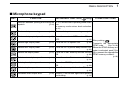
■ Microphone keypad
KEY
FUNCTION
SECONDARY FUNCTION (
+key)
OTHER FUNCTIONS
Switches between opening and closing the In VFO mode enters operating band selecsquelch.
(p. 24) tion.
In memory mode enters bank selection.
(p. 63)
Starts and stops scanning.
(p. 74) Starts and stops tone scanning.
Starts and stops priority watch.
(p. 79) Turns the one-touch PTT function ON and
OFF.
(p. 26)
Selects high output power.
(p. 21) Turns the DTCS squelch ON.
Selects mid. output power.
(p. 21) Turns the DTCS pocket beep function ON.
(p. 85)
Selects low output power.
(p. 21) Turns the DTMF memory encoder function
ON.
(p. 82)
Selects minus duplex operation.
(p. 31) Turns the subaudible tone encoder ON.
(p. 31)
Selects plus duplex operation.
(p. 31) Turns the CTCSS pocket beep function
ON.
(p. 85)
Selects simplex operation.
(p. 31) Turns the tone squelch function ON.
Increases audio output level.
(p. 20) Sends a 1750 Hz tone signal while pushing
and holding.
(p. 33)
(p. 89)
(p. 85)
(p. 85)
After pushing
:
Transmits the appropriate
DTMF code.
(pgs. 33, 83)
When the DTMF memory encoder is activated, push [0] to
[9] to transmit the appropriate
DTMF memory contents .
(p. 83)
1
2
3
4
5
6
7
8
9
10
11
12
13
14
15
16
17
18
19
12
1
PANEL DESCRIPTION
KEY
FUNCTION
SECONDARY FUNCTION (
+key)
OTHER FUNCTIONS
➥ Cancels frequency entry.
(p. 17) ➥ Stores the set frequency, etc., into the
selected memory channel when pushed
➥ Cancels the scan or priority watch.
and held.
(pgs. 74, 80)
(p. 62)
➥ Exit set mode.
(p. 95) ➥ Advances the memory channel number
when continuously pushed after programming is completed.
(p. 62)
➥ Enters MENU screen.
(p. 95) DTMF memory encoder function OFF.
➥ Enters selected set mode.
(p. 95)
(p. 82)
➥ Enters programmable condition after selecting a set mode item.
(p. 95)
After pushing
:
Turns the subaudible tone encoder, pocket Transmits the appropriate
(p. 17) beep or CTCSS/DTCS tone squelch OFF. DTMF code.
(pgs. 33, 83)
➥ Returns to the previous indication after
(pgs. 31, 85)
entering set mode.
(p. 95)
➥ Sets the keypad for numeral input.
Adjusts the squelch level increments.
Mutes the audio.
(p. 27)
(p. 20) • Mute function is released when any operation is performed.
Decreases audio output level.
Adjusts the squelch level decrement.
(p. 20) Sends a 1750 Hz tone signal for 0.5 sec.
(p. 33)
Locks the digit keys on the keypad (includ(p. 20) ing the A to D, # and M keys.
13
(p. 19)
PANEL DESCRIPTION
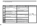
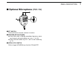
■ Optional Microphone (HM-154)
w
ON
q
e
OFF
q PTT SWITCH
Push and hold to transmit; release to receive.
w UP/DOWN KEYS [UP]/[DN]
➥ Push either key to change operating frequency, memory channel, set mode setting, etc. (pgs. 17, 60, 95)
➥ Push and hold either key for 1 sec. to start scanning.
(p. 74)
e UP/DN LOCK SWITCH
Slide to toggle [UP]/[DN] keys function ON and OFF.
1
1
2
3
4
5
6
7
8
9
10
11
12
13
14
15
16
17
18
19
14
2
SETTING A FREQUENCY
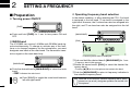
■ Preparation
D Turning power ON/OFF
[PWR]
D Operating frequency band selection
In the default condition, or after resetting the CPU, 2 m band
is assigned to the left band, 70 cm band is assigned to the
right band. However, the 2 m band can also be assigned into
the right, and 70 cm band can also be assigned into the left
band.
➥ Push and hold [PWR] for 1 sec. to turn power ON and
OFF.
[MAIN•BAND]
D MAIN band
[DIAL]
The IC-E2820 can receive 144 MHz and 430 MHz band signals simultaneously. To change or activate any of the functions or to change frequency via the microphone, you must
designate one band as the main band. The transceiver transmits a signal on the main band only.
Frequency band initial is displayed.
q Push and hold the desired band’s [MAIN•BAND] for 1 sec.
[MAIN•BAND]
➥ Push the desired band’s [MAIN•BAND] to select the main
band.
• “Q” indicates the main band.
BAND
15
➥ Push [BAND] to toggle the main band between
left and right bands.
• Frequency band initial appears.
wRotate the same band’s [DIAL] to select the desired frequency band.
• Pushing [Y]/[Z] on the microphone also selects the band.
ePush the [MAIN•BAND] to return to frequency indication in
the selected frequency band.
Note that in this manual, sections beginning with a microphone icon (as at left), designate operation via the HM-133
microphone.
SETTING A FREQUENCY
BANK
z Push [BAND] to select main band.
x Push and hold [BAND] for 1 sec. to enter frequency band selection.
• The frequency band is displayed.
Y/Z
c Push [Y]/[Z] to select the desired frequency
band.
v Push [CLR A(MW)] (or [BAND]) to exit the condition, and return to frequency indication.
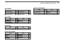
✔ About extra frequency bands— depending on versions
In addition to the 2 m and 70 cm ham bands, some versions
of the the IC-E2820 have extra frequency bands for each left
and right bands as follow.
See the specifications for the available frequency bands for
details.
Frequency
band initial*
Left band
Right band
127
136
146
222
375
440
500
900
✔
✔
✔
✔
✔
✔
✔
—
✔
✔
✔
—
✔
✔
✔
✔
*The frequency band initials are default indication only. Once the operating frequency is set in the band, the initial indication will be
changed.
✔: Available, —: Not available
2
D VFO and memory modes
The transceiver has 2 basic operating modes: VFO mode and
memory mode. Select VFO mode first to set an operating frequency.
[V/MHz•SCAN]
[M/CALL•MW]
VFO mode is selected.
“X” indicator appears when
memory mode is selected.
➥ Push the desired band’s [V/MHz•SCAN] to select VFO
mode.
• When VFO mode is already selected, the digits to the right of the
10 MHz or 1 MHz digits will disappear depending on version. In
this case, push [V/MHz•SCAN] again (or twice depending on version).
➥ Push [M/CALL•MW] to select memory mode.
• “X” indicator appears when memory mode is selected.
➥ Push [VFO/LOCK] to select VFO mode.
VFO/LOCK ➥ Push [MR/CALL] to select memory mode.
• The microphone controls the main band only. Push
[BAND] to toggle the main band, then push
[VFO/LOCK] or [MR/CALL], if necessary.
1
2
3
4
5
6
7
8
9
10
11
12
13
14
15
16
17
18
19
16
2
SETTING A FREQUENCY
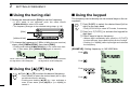
■ Using the tuning dial
■ Using the keypad
q Rotate the desired band’s [DIAL] to set the frequency.
The frequency can be directly set via numeral keys on the microphone.
• If VFO mode is not selected, push the same band’s
[V/MHz•SCAN] to select VFO mode.
• The frequency changes in the selected tuning steps. (p. 18)
ENT
C
z Push [BAND] to select the desired band (left or
right) as the main band.
• Push [VFO/LOCK] to select VFO mode, if necessary.
[DIAL]
x Push [ENT C(T-OFF)] to activate the keypad for
digit input.
c Push 6 keys to input a frequency.
[V/MHz•SCAN]
• When a digit is mistakenly input, push [ENT C(T-OFF)]
to clear the input, then repeat input from the 1st digit.
• Pushing [CLR A(MW)] clears input digits and retrieves
the frequency.
wTo change the frequency in 1 MHz (10 MHz for some versions)
steps, push [V/MHz•SCAN], then rotate [DIAL].
• Pushing and holding [V/MHz•SCAN] for 1 sec. starts scan function. If scan starts, push [V/MHz•SCAN] again to cancel it.
[EXAMPLE]: Setting frequency to 145.3625 MHz.
Push
While 1 MHz tuning step is selected,
the digit below 1 MHz disappear.
While 10 MHz tuning step is selected,
the digit below 10 MHz disappear.
■ Using the [Y]/[Z] keys
Push
Push
➥ Push [Y] or [Z] to select the desired frequency.
YZ
17
• Push [BAND] to select the desired band (left or right)
as the main band in advance.
• Pushing and holding [Y]/[Z] for 1 sec. activates a
scan. If scan starts, push [Y]/[Z] or [CLR A(MW)] to
cancel it.
Push
SETTING A FREQUENCY
2
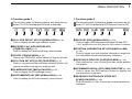
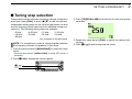
■ Tuning step selection
Tuning steps are the minimum frequency change increments
when you rotate [DIAL] or push [Y]/[Z] on the microphone.
Independent tuning steps for the left and right bands, as well
as each frequency band can be set for individual tuning convenience. The following tuning steps are available.
• 5 kHz*
• 15 kHz*
• 50 kHz
• 6.25 kHz*
• 20 kHz
• 10 kHz
• 25 kHz
• 12.5 kHz
• 30 kHz
*Not selectable in 900 MHz band.
NOTE: For convenience, select a tuning step that matches
the frequency intervals of repeaters in your area.
q Push the desired band’s [MAIN•BAND] to select the main
band.
• Push the same band’s [V/MHz•SCAN] to select VFO mode, if
necessary.
w Push [F•
[F•
[TS]
]
] to display the function guide.
ePush [TS](M/CALL•MW) (Left band’s) to enter tuning step
set mode.
rRotate the same band’s [DIAL] to select the desired tuning step.
tPush [F• ] to exit tuning step set mode.
1
2
3
4
5
6
7
8
9
10
11
12
13
14
15
16
17
18
19
18
2
SETTING A FREQUENCY
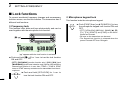
■ Lock functions
To prevent accidental frequency changes and unnecessary
function access, use the lock function. The transceiver has 2
different lock functions.
D Frequency lock
]
“
” appears while the lock function is activated.
➥ Push and hold [F•
ON and OFF.
] for 1 sec. to turn the lock function
• [PTT], [DUP•MONI] (monitor function only), [VOL], [SQL] and
[MAIN•BAND] (main band selection only) can be used while the
channel lock function is in use. Also, TONE-1, TONE-2, DTMF
tones or DTMF memory contents can be transmitted from the microphone.
VFO/LOCK
19
This function locks the microphone keypad.
16KEY-L
This function locks dials and keys electronically and can be
used together with the microphone lock function.
[F•
D Microphone keypad lock
➥ Push and hold [VFO/LOCK] for 1 sec. to
turn the lock function ON and OFF.
➥ Push [FUNC] then [SQLZ D(16KEY-L)] to turn
the microphone keypad lock function ON and
OFF.
• [PTT], [VFO/LOCK], [MR/CALL], [BAND], [Y], [Z],
[F-1], [F-2], [DTMF-S] and [FUNC] on the microphone can be used.
• All keys on the transceiver can be used.
• The keypad lock function is released when the
power is turned OFF then ON again.
BASIC OPERATION
■ Receiving
3
■ Transmitting
q Set the audio level for the main band.
➥ Push the desired band’s [MAIN•BAND].
➥ Push and hold [DUP•MONI] for 1 sec. to open the
squelch.
➥ Rotate the main band’s [VOL] to adjust the audio level.
➥ Push the [DUP•MONI] to close the squelch.
w Set the squelch level.
➥ Rotate the main band’s [SQL] fully counterclockwise in
advance, then rotate the [SQL] clockwise until the noise
just disappears.
• When interference due to strong signals is received, rotate
[SQL] clockwise past 12 o'clock for attenuator operation. (p. 22)
e Set the operating frequency in the main band. (pgs. 15–17)
rWhen receiving a signal on the selected frequency, squelch
opens and the transceiver emits audio.
• “BUSY” appears and the S/RF
indicator shows the relative
signal strength for the reAppears when receiving a signal.
ceived signal.
CAUTION: Transmitting without an antenna may damage
the transceiver.
NOTE: To prevent interference, listen on the channel before transmitting by pushing and holding [DUP•MONI] for
1 sec., or [MONI 1(BANK)] on the microphone.
q Select the main band. (p. 15)
w Set the operating frequency. (pgs. 15–17)
• Select output power if desired. See section at right for details.
e Push and hold [PTT] to transmit.
• “$” appears.
• The S/RF indicator shows the output power selection.
• A one-touch PTT function is available. See p. 26 for details.
•“
” appears on the sub-band screen according to the selected frequency band.
r Speak into the microphone using your normal voice level.
• DO NOT hold the microphone too close to your mouth or speak
too loudly. This may distort the signal.
t Release [PTT] to return to receive.
✔CONVENIENT!
The main band’s audio and squelch level can also
SQLY/Z be adjusted with [VOLY(TONE-1)]/[VOLZ 0(TONE-2)]
D/#
and [SQLY D(MUTE)]/[SQLZ #(16KEY-L)], respectively.
• “VOL” for audio or “SQL” for squelch appears during set.
VOLY/Z
M/0
Show set level
IMPORTANT! (for 50 W transmission):
The IC-E2820 is equipped with protection circuits to protect
the power amplifier circuit from high temperature. When the
transceiver temperature becomes extremely high, the transceiver reduces transmit output power to 5 W (approx.) automatically.
1
2
3
4
5
6
7
8
9
10
11
12
13
14
15
16
17
18
19
20
3
BASIC OPERATION
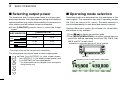
■ Selecting output power
■ Operating mode selection
The transceiver has 3 output power levels to suit your operating requirements. Low output powers during short-distance
communications may reduce the possibility of interference to
other stations and will reduce current consumption.
Operating modes are determined by the modulation of the
radio signals. The transceiver has total 5 operating modes
(FM, FM-N, AM, AM-N and DV* modes). The mode selection is
stored independently for each band and memory channel.
➥ Push [LOW•PRIO] several times to select the output
power.
S/RF INDICATOR
POWER OUTPUT
VHF
UHF
High:
50 W
50 W
Mid:
15 W*
15 W*
Low:
5 W*
5 W*
Typically, AM mode is used for the air band (118–136.995 MHz),
and receive is only available.
q Push [F• ] to display the function guide.
wPush [MODE](V/MHz•SCAN) (Left band’s) several times to
select the desired operating mode from FM, FM-N, AM,
AM-N and DV* in main band.
*Available only when the optional UT-123 is installed.
*approx.
• The output power can be changed while transmitting.
The microphone can also be used to select output power.
HIGH
4
MID
5
LOW
6
21
➥ Push [HIGH 4(DTCS)] for high output power;
[MID 5(DTCSS)] for middle output power; and
[LOW 6(DTMF)] for low output power.
• The output power can be changed via the microphone
during receive only.
[MODE]
Operating mode in main band is selectable.
BASIC OPERATION
3
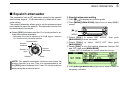
■ Squelch attenuator
The transceiver has an RF attenuator related to the squelch
level setting. Approx. 10 dB attenuation is obtained at maximum setting.
The squelch attenuator allows you to set the minimum signal
level needed to open the squelch. The attenuator function can
be deactivated in set mode.
➥ Rotate [SQL] clockwise past the 13 o’clock position to activate the squelch attenuator.
• Attenuation level can be adjusted up to 10 dB (approx.) between
13 o’clock and fully clockwise position.
Noise squelch
Squelch
threshold
Squelch is
open.
Shallow
Squelch
attenuator
D Squelch attenuator setting
q Push [F• ] to display the function guide.
wPush [MENU](V/MHz•SCAN) (Right band’s) to enter MENU
screen.
[F•
]
[MENU]
eRotate [DIAL] to select “SET MODE,” then push
[MAIN•BAND] to enter set mode.
rRotate [DIAL] to select “AUTO ATT” then push
[MAIN•BAND].
tRotate [DIAL] to turn the squelch attenuator function ON
and OFF, then push [MAIN•BAND]
• Select “OFF” to deactivate the squelch attenuator function.
Deep
NOTE: The squelch attenuator functions even when the
monitor function is in use. Thus it is recommended to set
the [SQL] control between the 10 and 13 o'clock positions
when using the monitor function.
y Push [BACK](V/MHz•SCAN) (Right band’s) twice to return to
frequency indication.
1
2
3
4
5
6
7
8
9
10
11
12
13
14
15
16
17
18
19
22
3
BASIC OPERATION
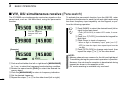
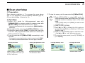
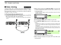
■ V/V, U/U simultaneous receive (Para-watch)
The IC-E2820 can simultaneously receive two signals on the
same band, such as 144 MHz band, using the para-watch
function.
Can be switched
between VHF and
UHF
To activate the para-watch function from the HM-133, enter
the desired frequencies for each the left and right bands using
the direct frequency input capability via the keypad; or perform the following operation.
ENT
C
z Push [BAND] to select the desired band (left or
right) as the main band.
• Push [VFO/LOCK] to select VFO mode, if necessary.
x Push [ENT C(T-OFF)] to activate the keypad for
digit input.
c Push 6 keys to input a frequency.
• When a digit is mistakenly input, push [ENT C(TOFF)] to clear the input, then repeat input from the
1st digit.
[Example]
qPush and hold either the left or right band’s [MAIN•BAND]
for 1 sec. to select the frequency band selecting condition.
wRotate the same band’s [DIAL] to select the desired frequency band.
e Push the [MAIN•BAND] to return to frequency indication.
r Set the desired frequency.
t Repeat the steps q to r for the other band (left or right).
23
v Push [VFO/LOCK] to change main band, then
repeat the steps z to c for the other band.
NOTE:
• Memory channels are common for the left and right band.
• Transmitting during the para-watch operation is possible.
However, the sub-band’s reception is deactivated during
transmit as shown in the example at left.
• DV mode receiving is available only one band.
BASIC OPERATION
3
■ Sub-band mute/busy beep
■ Monitor function
The sub-band mute function automatically cuts out sub-band
audio signals when both main and sub-band signals are received simultaneously.
This function is used to listen to weak signals without disturbing the squelch setting.
While operating on the main band, a beep sounds to inform
you that a signal was received on the sub-band.
q Push [F• ] to display the function guide.
wPush [MENU](V/MHz•SCAN) (Right band’s) to enter MENU
screen.
eRotate [DIAL] to select “SOUNDS” then push
[MAIN•BAND].
rRotate [DIAL] to select “SUB BAND MUTE” or “SUB
BAND BEEP” then push [MAIN•BAND].
tRotate [DIAL] to turn the sub-band mute or sub-band beep
function ON and OFF then push [MAIN•BAND].
y Push [BACK](V/MHz•SCAN) (Right band’s) twice to exit set
mode.
u When a signal is received on MAIN band, “
” appears as below.
Appears when a signal is received on MAIN band.
[DUP•MONI]
➥ After pushing [MAIN•BAND], push and hold [DUP•MONI]
for 1 sec. to open the squelch.
• “BUSY” blinks.
• Push [DUP•MONI] again to cancel the function.
➥ Push [MONI 1(BANK)] to open the squelch.
MONI
1
• Push [BAND] to select the desired band (left or right)
as the main band in advance.
• Push [MONI 1(BANK)] again to cancel the function.
NOTE: When the [SQL] adjustment is set too far clockwise, (12–5 o’clock position) the squelch attenuator is activated. To monitor weak signals on the operating frequency,
deactivate the squelch attenuator function. See page 22
for details.
1
2
3
4
5
6
7
8
9
10
11
12
13
14
15
16
17
18
19
24
3
BASIC OPERATION
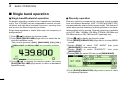
■ Single band operation
D Single band/Dualwatch operation
D Diversity operation
Dualwatch operation monitors two frequencies simultaneously. The IC-E2820 has two independent receiver circuits:
left band, and right band (available frequencies, operating mode
and functions are different depending on bands).
Single band operation is useful when only one frequency is
being watched.
Diversity receiving compares the receiving signal strength
from two different antennas, [ANT1 TX/RX] and [ANT2 RX],
and automatically selects the strongest signal. This feature is
useful when you are listening in a moving vehicle or the transmitting station itself is moving. Diversity receiving is available
on the 127 MHz, 136 MHz, 146 MHz, 375 MHz, 440 MHz and
500 MHz bands on FM, FM-N and DV (optional) only.
q Push [F• ] to display the function guide.
wPush [SNGL](M/CALL•MW) (Right band’s) to select the single band operation mode.
• Both left and right band’s [DIAL], [MAIN•BAND], [VOL], [SQL],
[V/MHz•SCAN] and [M/CALL•MW] can be used for operation.
q Push [F• ] to display the function guide.
wPush [MENU](V/MHz•SCAN) (Right band’s) to enter MENU
screen.
eRotate [DIAL] to select “SET MODE” then push
[MAIN•BAND] to enter set mode.
rRotate [DIAL] to select “DIVERSITY” then push
[MAIN•BAND].
tRotate [DIAL] to select ON, then push [MAIN•BAND].
ePush [F• ] to display the function guide, then push
[DUAL](M/CALL•MW) (Right band’s) to return to dualwatch
operation mode.
yPush [BACK](V/MHz•SCAN) (Right band’s) twice to return
to frequency indication.
25
BASIC OPERATION
3
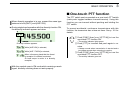
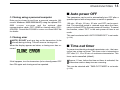
■ One-touch PTT function
When diversity operation is in use, connect the same type
antenna to both [ANT1] and [ANT2 RX].
➥ During single band operation with the diversity function ON,
the diversity indicator appears as below.
The PTT switch can be operated as a one-touch PTT switch
(each push toggles between transmit/receive). Using this
function you can transmit without pushing and holding the
PTT switch.
To prevent accidental, continuous transmissions with this
function, the transceiver has a time-out timer. See p. 101 for
details.
PTT-M
z Push [FUNC] then [PRIO 3(PTT-M)] to turn the
one-touch PTT function ON.
• The activity indicator lights green.
Diversity indicator appears.
While [ANT2 RX] is selected;
While [ANT1 TX/RX] is selected;
When a frequency band that the diversity reception is inhibited is selected.
Or band scope is active in a diversity
reception.
With the squelch open in FM mode while receiving a weak
signal, diversity receiving does not work properly.
x Push [PTT] to transmit and push again to receive.
• A beep sounds when transmission is started and a
long beep sounds when returning to receive.
c Push [FUNC] then [PRIO 3(PTT-M)] to turn the
one-touch PTT function OFF.
• The activity indicator goes out.
1
2
3
4
5
6
7
8
9
10
11
12
13
14
15
16
17
18
19
26
3
BASIC OPERATION
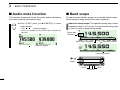
■ Audio mute function
■ Band scope
This function temporarily mutes the audio without disturbing
the volume setting. (microphone only)
The band scope function allows you to visually check a specified frequency range around the center frequency.
➥ Push [FUNC] then [SQLY D(MUTE)] to mute
audio signals.
About the sweep steps: The specified tuning step in each
frequency band (in VFO mode) or programmed tuning step
(in memory mode) is used during sweep.
MUTE
• The “
” indicators appear.
• Push [CLR A(MW)] (or any other key) to cancel the
function.
Sweep step
indication
Band scope indication
“
Frequency marker
” indicators appear
Frequency marker
[F•
]
[DIAL]
[SCP]
[CLR]
[CENT]
27
BASIC OPERATION
3
D Single sweep
D Monitoring a signal
q Set the desired frequency as band scope center frequency.
w Push [F• ] to display the function guide.
ePush [SCP](DUP•MONI) to start a single sweep.
If you find a signal that you want to monitor during/after
sweep, you can monitor the signal with the following operation.
qPush [F• ] to display the function guide, then push
[SCP](DUP•MONI) to cancel the continuous sweep, if necessary.
w Rotate [DIAL] to tune into the desired signal.
ePush [CENT](TONE•DTMF) to return to the center frequency.
• 1 short beep sounds.
• Signal strengths appear starting from the lower edge of the
range.
rRotate [DIAL] to set the frequency marker to the desired
signal and set the frequency of the signal.
tPush [F• ] to display the function guide, then push
[CLR](LOW•PRIO) to clear the band scope.
D Continuous sweep
q Set the desired frequency as band scope center frequency.
w Push [F• ] to display the function guide.
ePush and hold [SCP](DUP•MONI) for 1 sec. to start continuous sweep.
• 1 short and 1 long beeps sound.
• Signal strengths appear starting from the center of the range.
rTo stop sweeping, push [F• ] to display the function
guide, then push [SCP](DUP•MONI).
tPush [F• ] to display the function guide, then push
[CLR](LOW•PRIO) to clear the band scope.
The receive audio during sweeping can be muted in
sounds set mode. See page 109 for details.
1
2
3
4
5
6
7
8
9
10
11
12
13
14
15
16
17
18
19
28
4
REPEATER OPERATION
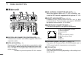
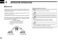
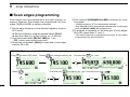
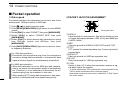
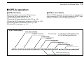
■ General
• Repeater operation flow chart
Repeaters allow you to extend the operational range of your
radio because a repeater has much higher output power than
the typical transceiver.
Step 1:
Set the desired band to operate the repeater.
Normally, a repeater has independent frequencies for each
receiver and transmitter.
A subaudible tone may also be required to access a repeater.
Step 2:
Set the desired receive frequency (repeater output frequency).
Reference amateur radio handbooks and local ham magazines for details of local repeaters such as repeater input/output frequencies and locations.
Repeater example;
Receives the 434.540 MHz signal
and the detected audio signals are
transmitted on 439.540 MHz simultaneously.
Step 3:
Set the duplex (shift) direction (– duplex or +duplex).
- Set the offset frequency (amount of shift), if required.
Step 4:
Set the subaudible tone (repeater tone) encoder function ON.
- Set the subaudible tone frequency, if required.
• Repeater settings can be stored into a memory channel.
Station A:
Tx: 434.540 MHz
Rx: 439.540 MHz
29
Station B:
Tx: 434.540 MHz
Rx: 439.540 MHz
REPEATER OPERATION
4
■ Accessing a repeater
qSet the receive frequency (repeater output frequency) on
the main band. (pgs. 15–17)
wPush [DUP•MONI] one or two times, to select minus duplex or plus duplex.
• “DUP–” or “DUP+” appears to indicate the transmit frequency for
minus shift or plus shift, respectively.
• When the auto repeater function is turned ON (available for the
USA version only), steps w and e are not necessary. (p. 35)
r Push and hold [PTT] to transmit.
• The displayed frequency automatically changes to the transmit
frequency (repeater input frequency).
• If “OFF” appears, confirm that the offset frequency (p. 34) is set
correctly.
t Release [PTT] to receive.
“DUP–” or “DUP+” appears
While receiving
[DUP•MONI]
ePush [TONE•DTMF] several times to turn ON the subaudible tone encoder, according to repeater requirements.
• “TONE” appears
• 88.5 Hz is set as the default; refer to p. 32 for tone frequency settings.
• When the repeater requires a different tone system, see p. 33.
“TONE” appears
[TONE•DTMF]
While transmitting
yPush [DUP•MONI] to check whether the other station’s
transmit signal can be received directly.
uTo return to simplex operation, push [DUP•MONI] once or
twice, to clear the “DUP–” or “DUP+” indicator.
iTo turn OFF the subaudible tone encoder, push
[TONE•DTMF] several times until no tone indicators appear.
1
2
3
4
5
6
7
8
9
10
11
12
13
14
15
16
17
18
19
30
4
REPEATER OPERATION
DUP–
7
DUP+
8
z Set the receive frequency (repeater output frequency) on the main band. (pgs. 16, 17)
x Push [DUP– 7(TONE)] to select minus duplex;
push [DUP+ 8(TSQLS)] to select plus duplex.
• “DUP–” or “DUP+” appears.
Push
Push
c Push [FUNC] then [DUP– 7(TONE)] to turn ON
the subaudible tone encoder according to repeater requirements.
• Refer to p. 32 for the tone frequency setting.
• When the repeater requires a different tone system,
see p. 33.
Push
then
,
.
v Push and hold [PTT] to transmit.
b Release [PTT] to receive.
n Push [MONI 1(BANK)] to check whether the
other station’s transmit signal can be received
directly.
31
SIMP
9
m Push [SIMP 9(TSQL)] to return to simplex operation.
• “DUP+” or “DUP–” indicator disappears.
, To turn OFF the subaudible tone encoder, push
[FUNC] then [ENT C(T-OFF)].
REPEATER OPERATION
4
■ Subaudible tones (Encoder function)
D Subaudible tones
qSelect the main band, mode/channel you wish to set the
subaudible tones to, such as VFO mode or memory/call
channel.
w Push [F• ] to display the function guide.
ePush [MENU](V/MHz•SCAN) (Right band’s) to enter MENU
screen.
rRotate [DIAL] to select “DUP/TONE…” then push
[MAIN•BAND].
tRotate [DIAL] to select “REPEATER TONE” then push
[MAIN•BAND].
yRotate [DIAL] to select and set the desired subaudible frequency, then push [MAIN•BAND].
[F•
SET
B
z Set the main band, mode/channel you wish to
set the subaudible tones for, such as VFO mode
or memory/call channel.
• The subaudible tone frequency is independently programmed into each mode or channel.
x Push [SET B(D-OFF)] to enter MENU screen.
c Push [Y] or [Z] to select “DUP/TONE…” then
push [SET B(D-OFF)].
v Push [Y] or [Z] to select “REPEATER TONE”
then push [SET B(D-OFF)].
b Push [Y] or [Z] to select the desired subaudible
tone frequency then push [SET B(D-OFF)].
]
Push
[DIAL]
[MAIN•BAND]
[MENU]
uPush [BACK](V/MHz•SCAN) (Right band’s) twice to exit
DUP/TONE set mode.
NOTE: The subaudible tone encoder frequency can be set
in a memory/call channel temporarily. However, the set frequency is cleared once another memory channel or VFO
mode is selected. To store the tone frequency permanently,
overwrite the channel information.
n Push [CLR A(MW)] to return VFO mode.
• Subaudible tone frequency list
67.0
69.3
71.9
74.4
77.0
79.7
82.5
85.4
88.5
91.5
94.8
97.4
100.0
103.5
107.2
110.9
114.8
118.8
123.0
127.3
131.8
136.5
141.3
146.2
151.4
156.7
159.8
162.2
165.5
167.9
(unit: Hz)
171.3
173.8
177.3
179.9
183.5
186.2
189.9
192.8
196.6
199.5
203.5
206.5
210.7
218.1
225.7
229.1
233.6
241.8
250.3
254.1
1
2
3
4
5
6
7
8
9
10
11
12
13
14
15
16
17
18
19
32
4
REPEATER OPERATION
D 1750 Hz tone
D DTMF tones
➥ Push [DTMF-S], then push the keys of the deDTMF-S
sired DTMF digits.
• The function indicator lights green.
• 0–9, A–D, ✱(E) and #(F) are available.
• When “1” is displayed, cancel the DTMF memory
encoder in advance. (p. 82)
• Push [DTMF-S] again to return the keypad to normal function control.
Push
,
The microphone has 1750 Hz tone capability, used for ring
tone when calling, etc.
z Push [FUNC].
TONE-1
• The function indicator lights orange.
x Push [✱(TONE-1)] to transmit a 1750 Hz tone
call signal for 0.5 sec.; push and hold
TONE-2
[0(TONE-2)] to transmit a 1750 Hz tone call
signal for an arbitrary period.
• The function indicator goes out automatically.
then push desired keys.
✔ For your convenience!
The transceiver has 16 DTMF memory channels for autopatch operation. See p. 81 for details.
33
Push
,
then
or
.
REPEATER OPERATION
4
■ Offset frequency
When communicating through a repeater, the transmit frequency is shifted from the receive frequency by an amount
determined by the offset frequency.
Independent offset frequencies can be set for each operating
frequency band.
qPush [MAIN•BAND] to select the desired band (left or right)
as the main band.
wSelect the desired mode/channel you wish to set the offset
frequency for, such as VFO mode or memory/call channel.
ePush [F• ] to display the function guide then push
[MENU](V/MHz•SCAN) (Right band’s) to enter MENU
screen.
rRotate [DIAL] to select “DUP/TONE…”, then push
[MAIN•BAND].
tRotate [DIAL] to select “OFFSET FREQ” item, then push
[MAIN•BAND].
yRotate [DIAL] to set the desired offset frequency.
• Push [MHz](V/MHz•SCAN) (Left band’s) to turn 1 MHz tuning
ON and OFF
[F•
]
[DIAL]
[MAIN•BAND]
[MENU]
uPush [BACK](V/MHz•SCAN) (Right band’s) twice to exit
DUP/TONE set mode.
SET
B
z Push [BAND] to select the desired band (left or
right) as the main band.
• Enter the desired frequency via the keypad if necessary.
x Select the desired mode/channel you wish to
set the offset frequency for, such as VFO mode
or memory/call channel.
• The offset frequency can be independently programmed into each mode or channel.
c Push [SET B(D-OFF)] to enter MENU screen.
v Push [Y] or [Z] to select “DUP/TONE…” then
push [SET B(D-OFF)].
b Push [Y] or [Z] to select “OFFSET FREQ” then
push [SET B(D-OFF)].
n Push [Y] or [Z] to set the desired offset.
• Direct frequency entry from the keypad is not possible.
m Push [CLR A(MW)] to exit set mode.
NOTE: The offset frequency can be set in a
memory/call channel temporarily. However, the
set frequency is cleared once another memory
channel or VFO mode is selected. To store the
offset frequency permanently, overwrite the
channel information.
1
2
3
4
5
6
7
8
9
10
11
12
13
14
15
16
17
18
19
34
5
35
DV MODE OPERATION (Optional UT-123 is required)
■ Digital mode operation
■ Call sign programming
The IC-E2820 can be operated in digital voice mode and lowspeed data operation for both transmit and receive when the
optional UT-123 is installed. Also, position data transmission
and reception are available with the UT-123. A GPS antenna
is supplied with the UT-123.
Four types of call sign memories are available: your own call
sign “MY CALL SIGN,” other station call sign “YOUR CALL
SIGN,” repeater call sign “RPT1 CALL SIGN” and “RPT2
CALL SIGN.” “MY CALL SIGN” can store up to 6 call signs,
“YOUR CALL SIGN” can store up to 60 call signs and
“RPT1/2 CALL SIGN” can store up to 60 call signs, and each
call sign can be programmed with up to 8 characters.
DV MODE OPERATION (Optional UT-123 is required)
5
D Your own call sign programming
Your own call sign must be programmed for both digital voice
and low-speed data communications (including GPS transmission).
q Push [F• ] to display the function guide.
wPush [MENU](V/MHz•SCAN) (Right band’s) to enter MENU
screen.
eRotate [DIAL] to select “CALL SIGN MEMORY” then push
[MAIN•BAND].
rRotate [DIAL] to select “MY CALL SIGN MEMORY” then
push [MAIN•BAND].
tRotate [DIAL] to select the desired call sign channel (M01
to M06), then push [MAIN•BAND].
yRotate [DIAL] to select the desired character, then push
[>](M/CALL•MW) (Left band’s) to move the cursor right.
• Push [<](V/MHz•SCAN) (Left band’s) to move the cursor left.
• Up to 8-character call signs can be entered.
• Push [ABC](TONE•DTMF) to select the character group from
capital letter characters.
• Push [12/](M/CALL•MW) (Right band’s) to select the character
group from numbers or symbols.
• Push [CLR](DUP•MONI) to clear the selected character.
u Repeat step y until your own call sign is programmed.
iPush [>](M/CALL•MW) (Left band’s) several times to move
the cursor to “/” position.
• A to Z, 0 to 9 and “/” characters are available.
• If no note is required, skip steps i and o, go to step !0.
o Repeat step y to program the desired 4-character note.
!0 Push [MAIN•BAND] to store the programmed call sign (or
with note).
!1 Push [BACK](V/MHz•SCAN) (Right band’s) three times to
return to frequency indication.
1
2
3
4
5
6
7
8
9
10
11
12
13
14
15
16
17
18
19
36
5
DV MODE OPERATION (Optional UT-123 is required)
D Station call sign programming
Station call signs must be programmed for the specified station call as well as repeater operation in all digital voice, lowspeed data and GPS communications.
q Push [F• ] to display the function guide.
wPush [MENU](V/MHz•SCAN) (Right band’s) to enter MENU
screen.
eRotate [DIAL] to select “CALL SIGN MEMORY” then push
[MAIN•BAND].
rRotate [DIAL] to select “YOUR CALL SIGN MEMORY”
then push [MAIN•BAND].
tRotate [DIAL] to select the desired call sign channel (U01 to
U60), then push [MAIN•BAND].
uRepeat step y until the desired station call sign is programmed.
iPush [MAIN•BAND] to store the programmed call sign.
oPush [BACK](V/MHz•SCAN) (Right band’s) three times to
return to frequency indication.
yRotate [DIAL] to select the desired character, then push
[>](M/CALL•MW) (Left band’s) to move the cursor right.
• Push [<](V/MHz•SCAN) (Left band’s) to move the cursor left.
• Up to 8-character call signs can be entered.
• Push [ABC](TONE•DTMF) to select the character group from
capital letter characters.
• Push [12/](M/CALL•MW) (Right band’s) to select the character
group from numbers or symbol.
• Push [CLR](DUP•MONI) to clear the selected character.
37
DV MODE OPERATION (Optional UT-123 is required)
5
■ Digital voice mode operation
qSet the desired band (Left or Right) as the main band. (p. 15)
• Select output power, if desired. (p. 21)
w Select DV mode. (p. 21)
e Set your own call sign for DV operation as follows.
z Push [F• ] twice to display the function guide 2.
xPush [CS](V/MHz•SCAN) (Left band’s) to display call sign
screen.
cRotate [DIAL] to select “MY” then push [MAIN•BAND].
vRotate [DIAL] to select the desired your own call sign
memory channel, then push [BACK](V/MHz•SCAN)
(Right band’s) to set “MY CALL SIGN.”
• See page 36 for your own call sign programming details.
rSet the desired call sign as described in “When calling the
desired station (p. 39)” or “When sending a CQ (p. 39).”
tPush and hold [PTT] to transmit and speak into the microphone at normal voice level.
• “$” appears and the RF meter shows the output power.
y Release [PTT] to return to receive.
• The other station call sign will be received.
• Received call signs can be stored into the received call record
automatically. See page 47 for details.
NOTE: The digital mode operation is vastly different from
FM mode. One of the differences is that in digital mode the
squelch does not function as in FM mode. Changing the
squelch setting will not open it to hear the hiss of “White
Noise.” It only activates for digital squelch functions such
as CSQL (Digital code squelch) or DSQL (Digital call sign
squelch).
1
2
3
4
5
6
7
8
9
10
11
12
13
14
15
16
17
18
19
38
5
DV MODE OPERATION (Optional UT-123 is required)
D When calling the desired station
Continued instruction from step v on page 38.
bRotate [DIAL] to select “YOUR,” then push [MAIN•BAND].
• YOUR CALL SIGN screen is displayed.
nRotate [DIAL] to select the call sign channel in which desired station’s call sign is programmed.
• See page 38 for station call sign programming details.
mPush [BACK](V/MHz•SCAN) (Right band’s) to set the station’s call sign and return to CALL SIGN screen.
,Push [BACK](V/MHz•SCAN) (Right band’s) again to return
to function guide 2 indication.
. Perform the instruction steps t to y on page 38.
D When sending a CQ
Continued instruction from step v on page 38.
b Push [CQ](DUP•MONI) to set “CQCQCQ” as the call sign.
nPush [BACK](V/MHz•SCAN) (Right band’s) to return to
function guide 2 indication.
m Perform the instruction step t to y on page 38.
39
✔ For your information!
Your own (MY) call sign, Station call sign and repeater call
sign can also be programmed/edited in “CALL SIGN” screen.
In addition, when editing a call sign stored in a call sign memory, regular memory or call channel, the default operation is to
over-write a programmed call sign in regular memory and call
channels. (Temporary operation without over-writing is possible.)
However, the edited call sign can store into a blank channel
automatically when “AUTO” is set with the EDIT RECORD
(p. 102).
zWhile displaying “CALL SIGN” screen, rotate [DIAL] to select
either “YOUR,” “RPT1/2” or “MY” then push [MAIN•BAND].
xRotate [DIAL] to select the desired call sign memory channel then push [MAIN•BAND].
cRotate [DIAL] to select the desired call sign memory channel then push [MAIN•BAND].
vRotate [DIAL] to select the desired character.
• Push [ABC](TONE•DTMF) to select the character group from
capital letter characters.
• Push [12/](M/CALL•MW) (Right band’s) to select the character
group from numbers or symbol.
• Push [>](M/CALL•MW) (Left band’s) or [<](V/MHz•SCAN) (Left
band’s) to move the cursor right or left, respectively.
• Push [CLR](DUP•MONI) to clear the selected character.
• Push [GW](LOW•PRIO) (available only when RPT1/2 is selected
in step z) to turn the gateway setting ON/OFF.
bAfter the desired call sign (up to 8-characters) is entered,
push [BACK](V/MHz•SCAN) (Right band’s).
DV MODE OPERATION (Optional UT-123 is required)
5
■ DV automatic detect
The “DV” mode indicator blinks when a non-DV signal is received during DV mode operation.
The IC-E2820 DV automatic detection monitors in FM mode
when other than DV mode signal is received.
qPush [F• ] to display the function guide.
wPush [MENU](V/MHz•SCAN) (Right band’s) to display the
MENU screen.
eRotate [DIAL] to select “DV SET MODE” then push
[MAIN•BAND].
rRotate [DIAL] to select “DV AUTO DETECT” then push
[MAIN•BAND].
tRotate [DIAL] to turn the DV automatic detect function ON
and OFF, then push [MAIN•BAND].
OFF : “DV” mode indicator blinks, however the transceiver receives in DV mode even if non-DV mode
signals are received. (default)
ON : “DV” mode indicator blinks and the transceiver
monitors the signal in FM mode.
yPush [BACK](V/MHz•SCAN) (Right band’s) twice to exit
from DV set mode.
NOTE: The received FM audio may be distorted when receiving an FM signal with the DV automatic detect function
active.
1
2
3
4
5
6
7
8
9
10
11
12
13
14
15
16
17
18
19
40
5
DV MODE OPERATION (Optional UT-123 is required)
■ About D-STAR system
In the D-STAR system, repeater linking via a 10 GHz band
backbone and internet network (gateway connection) capabilities are available. This system provides you with much
wider coverage range during digital voice mode operation.
• D-STAR system outline
Repeater A
Also, the D-STAR system repeaters are connectable through
the INTERNET— gateway connection capability.
10 GHz
Repeater B
440 MHz
440 MHz
Station A
Station B
Internet
network
10 GHz
Repeater D
Repeater C
440 MHz
Station C
41
For current repeater operation, stations that are communicating must both be in the same repeater’s operating area.
However, in the D-STAR system as in the illustration at left,
the repeaters can be linked via the system repeaters (with a
10 GHz signal). Thus stations A and B can communicate even
though they are in different repeater operating areas.
440 MHz
Station D
For example, when station B uses the gateway connection
station B can communicate with the station C!
By using the gateway connection, long distance DX communication may be possible with 144 or 440 MHz digital voice!
In the D-STAR system, an independent repeater’s operating
area is called an Area and a group that of linked repeaters via
a 10 GHz backbone is called a Zone.
DV MODE OPERATION (Optional UT-123 is required)
5
■ Digital repeater operation
Repeater call signs must be programmed for repeater operation in both digital voice and low-speed data communications.
D Repeater call sign programming
q Push [F• ] to display the function guide.
wPush [MENU](V/MHz•SCAN) (Right band’s) to enter MENU
screen.
eRotate [DIAL] to select “CALL SIGN MEMORY” then push
[MAIN•BAND].
rRotate [DIAL] to select “RPT CALL SIGN MEMORY” then
push [MAIN•BAND].
yRotate [DIAL] to select the desired character, then push
[>](M/CALL•MW) (Left band’s) to move the cursor right.
• Push [<](V/MHz•SCAN) (Left band’s) to move the cursor left.
• Push [ABC](TONE•DTMF) to select the character group from
capital letter characters.
• Push [12/](M/CALL•MW) (Right band’s) to select the character
group from numbers or symbols.
• Push [CLR](DUP•MONI) to clear the selected character.
• Push [GW](LOW•PRIO) to turn the gateway setting ON/OFF.
u Repeat step y until repeater call sign is programmed.
i Push [MAIN•BAND] to store the programmed call sign.
tRotate [DIAL] to select the desired call sign channel (R01 to
R60), then push [MAIN•BAND].
oPush [BACK](V/MHz•SCAN) (Right band’s) three times to
return to frequency indication.
1
2
3
4
5
6
7
8
9
10
11
12
13
14
15
16
17
18
19
42
5
DV MODE OPERATION (Optional UT-123 is required)
D Repeater operation in the same zone
qSet the desired repeater’s frequency, offset and shift direction in the main band. (pgs. 30, 31)
• Select DV mode in advance. (p. 21)
w Set your own call sign. (p. 38)
• See p. 36 for your own call sign programming.
e Set the desired station call sign. (p. 39)
• See p. 38 for station call sign programming.
r Set the repeater’s call sign as follows;
z Push [F• ] twice to display the function guide 2.
xPush [CS](V/MHz) (Left band’s) to display the “CALL
SIGN” screen.
cRotate [DIAL] to select “RPT1,” then push
[MAIN•BAND].
• RPT1 CALL SIGN screen is displayed.
vRotate [DIAL] to select the nearest repeater’s call sign
then push [BACK](V/MHz) (Right band’s).
bRotate [DIAL]
[MAIN•BAND].
to
select
“RPT2”
then
push
• RPT2 CALL SIGN screen is displayed.
nRotate [DIAL] to select the desired repeater’s (in the
same zone) call sign.
• Select “NOT USE✱” when not operating RPT2.
43
mPush [BACK](V/MHz•SCAN) (Right band’s) to exit “CALL
SIGN” screen.
t Push [PTT] to transmit; release to receive.
DV MODE OPERATION (Optional UT-123 is required)
5
• Setting example 1
Zone
Area 1
Repeater 1
: A11111
Area 2
Repeater 2
: A22222
Station A
: A2222A
✔ What is the area?
The Area is the communication range that is
covered by a local repeater.
The Local repeater is called an area repeater in
the D-STAR system.
❑ The setting when Station A is calling Station B
UR
: A2222B
R1
: A22222
R2
: NOT USED
MY
: A2222A
Station B
: A2222B
Area 3
(Gateway)
Repeater 3
: A33333
Repeater 4
: A44444
Station C
: A4444C
Internet
network
to another zone
Area 4
✔ What is the zone?
The Zone is composed of several areas, that
are linked by the 10 GHz microwave signal.
The areas 1 to 4 make up a zone in the example above.
❑ The setting when Station A is making a CQ call in area 1
UR
: CQCQCQ
R1
: A22222
R2
: A11111
MY
: A2222A
❑ The setting when Station A is calling Station C
UR
: A4444C
R1
: A22222
R2
: A44444
MY
: A2222A
1
2
3
4
5
6
7
8
9
10
11
12
13
14
15
16
17
18
19
44
5
DV MODE OPERATION (Optional UT-123 is required)
D Repeater operation into another zone
qSet the desired repeater’s frequency, offset and shift direction in the main band. (pgs. 30, 31)
• Select DV mode in advance. (p. 21)
w Set your own call sign. (p. 38)
• See p. 36 for your own call sign programming.
e Set the desired station call sign. (p. 39)
• When making a CQ call
Set the desired repeater’s (in a different zone) call sign into
“YOUR.” The symbol “/” which stands for “CQCQCQ” is
added at the 1st digit automatically.
• See p. 37 for station call sign programming.
r Set the repeater’s call sign as follows;
z Push [F• ] twice to display the function guide 2.
xPush [CS](V/MHz•SCAN) (Left band’s) to display the
“CALL SIGN” screen.
cRotate [DIAL] to select “RPT1,” then push
[MAIN•BAND].
• RPT1 CALL SIGN screen is displayed.
vRotate [DIAL] to select the nearest repeater’s call sign
then push [BACK](V/MHz) (Right band’s).
• If the nearest repeater is a gateway repeater, program the repeater’s call sign with “G” in the 8th digit.
45
bRotate [DIAL]
[MAIN•BAND].
to
select
“RPT2”
then
push
• RPT2 CALL SIGN screen is displayed.
nRotate [DIAL] to select the gateway repeater’s (in the
same zone) call sign.
• The call sign should have “G” in the 8th digit.
• When gateway repeater call sign is set in “RPT1,” select “NOT
USE✱” for “RPT2” setting.
mPush [BACK](V/MHz•SCAN) (Right band’s) to exit “CALL
SIGN” screen.
t Push [PTT] to transmit; release to receive.
DV MODE OPERATION (Optional UT-123 is required)
5
• Setting examle 2
Zone A
Area 1
Repeater 1
: A11111
Area 2
Repeater 2
: A22222
Station A
: A2222A
Area 3
(Gateway)
Repeater 3
: A33333
Internet
network
Area 4
Repeater 4
: A44444
Area 8
Repeater 8
: B88888
Station B
: A3333B
Zone B
Area 5
Repeater 5
: B55555
Area 6
Repeater 6
: B66666
Area 7
(Gateway)
Repeater 7
: B77777
Station C
: B6666C
❑ The setting when Station A is calling Station C
UR
: B6666C
R1
: A22222
R2
: A33333 G
MY
: A2222A
❑ The setting when Station A is making a CQ call in area 8
UR
: /B88888
R1
: A22222
R2
: A33333 G
MY
: A2222A
❑ The setting when Station B is calling Station C
UR
: B6666C
R1
: A33333 G
R2
: NOT USE✱
MY
: A3333B
1
2
3
4
5
6
7
8
9
10
11
12
13
14
15
16
17
18
19
46
5
DV MODE OPERATION (Optional UT-123 is required)
■ Received call sign
When a call is received in DV mode, the calling station and
the repeater call signs being used can be stored into the received call record. The stored call signs are viewable in the
following manner.
Up to 20 calls can be recorded.
ePush [MAIN•BAND] to display the received call details.
• CALLER
• CALLED
• RXRPT1
• RXRPT2
: The station call sign that made a call.
: The station call sign called by the caller.
: The repeater call sign used by the caller station.
: The repeater call sign linked from RXRPT1.
D Desired call record indication
q Display the RX call sign record screen;
Accessing from MENU screen:
z Push [F• ] to display the function guide.
xPush [MENU](V/MHz•SCAN) (Right band’s) to display the
“MENU” screen.
cRotate [DIAL] to select “RX CALL SIGN,” then push
[MAIN•BAND].
Accessing from function guide 2:
z Push [F• ] twice to display the function guide 2.
xPush [CD](M/CALL•MW) (Left band’s) to display the “RX
CALL SIGN” screen.
wRotate [DIAL] to select the desired record.
47
*The above screen is displayed when accessing the RX CALL
SIGN screen from function guide 2. A different screen is displayed
when accessing the screen from MENU screen.
rPush [MAIN•BAND] or [BACK](V/MHz•SCAN) (Right
band’s) to return to the “RX CALL SIGN” screen.
tPush [BACK](V/MHz•SCAN) (Right band’s) to exit from the
“RX CALL SIGN” screen.
✔ For your information
When receiving a call, the received station call sign is automatically displayed at the bottom line of the function display.
This can be turned ON in display set mode. (p.106)
DV MODE OPERATION (Optional UT-123 is required)
5
D One-touch reply
qAfter receiving a call, push [F• ] twice to display the
function guide 2.
wPush [R>CS](TONE•DTMF) to set the received call sign as
for the call.
[R>CS]
D One-touch reply using the call record
The stored call signs in the call record can be used to the call.
qPerform the steps q and w of “D Desired call record indication” described on the previous page.
➥ When selecting a call record via MENU screen:
w Push [MAIN•BAND] to display the call record details.
ePush [R>CS](V/MHz•SCAN) (Left band’s) to set the received call sign to that of the call record.
➥ Setting from function guide 2:
wPush [R>CS](TONE•DTMF) to set the received call sign to
that of the call record.
After the above operations, push [PTT] to transmit; release
to receive.
NOTE:
• Set your own call sign (MY) in advance. (p. 39)
• The call sign stored in “CALLER” is stored as “YOUR,”
“RXRPT1” is stored as “RPT2” and “RXRPT2” is stored
as “RPT1.”
• Error beeps sound when a call sign is received incorrectly, and no call sign is set in this case.
Important!
Setting call signs with the “One-touch reply using the call
record” operation as at left are for temporary operation only.
Therefore, the set call signs will be overwritten when another call record is used to set call signs.
• Never save into a call sign memory.
If you want to save the set call signs, see “Copying the call
record contents into call sign memory” (p. 50) for details.
✔ For your information
When a call specifying your call sign is received, the call signs
of the calling station and the repeater it is using can be used
for operation automatically.
• When “RX call sign auto write” (p. 101) is set to “AUTO,” the
station call sign in “CALLER” is set to “YOUR” automatically.
• When “Repeater call sign auto write” (p. 102) is set to
“AUTO,” the stored station call sign in “RXRPT1” is stored
as “RPT2” and “RXRPT2” is stored as “RPT1” automatically.
1
2
3
4
5
6
7
8
9
10
11
12
13
14
15
16
17
18
19
48
5
DV MODE OPERATION (Optional UT-123 is required)
■ Copying the call sign
D Copying the call sign memory contents
This function is convenient when modifying part of the current
call sign.
NOTE: Make sure that the “EDIT RECORD” item in DV set
mode is set to “AUTO” in advance. (p. 102)
q Push [F• ] twice to display the function guide 2.
wPush [CS](V/MHz•SCAN) (Left band’s) to display the “CALL
SIGN” screen.
eRotate [DIAL] to select “YOUR” or “RPT1/2” then push
[MAIN•BAND].
r Rotate [DIAL] to select the desired call sign channel.
• U01–U60 and R01–R60 are available.
t Push [MAIN•BAND].
• The selected call sign channel contents are copied into a blank
channel automatically and call sign programming mode is selected.
yEdit or modify the copied call sign as follows;
• Push [<](V/MHz•SCAN) (Left band’s) [>](M/CALL•MW) (Left
band’s) or to move the cursor left or right, respectively.
• Push [ABC](TONE•DTMF) to select the character group from
capital letter characters.
• Push [12/](M/CALL•MW) (Right band’s) to select the character
group from numbers or symbols.
• Push [CLR](DUP•MONI) to clear the selected character.
• Push [GW](LOW•PRIO) to turn the gateway setting ON/OFF.
(available only when “RPT1/2” is selected in step e)
49
uPush [BACK](V/MHz•SCAN) (Right band’s) to store the
edited/modified call sign into the selected blank channel,
or push [MAIN•BAND] to store the call sign into the channel and set for the call.
NOTE:
The message “FULL” is displayed when no blank channel
is available in the station or repeater call sign memory.
DV MODE OPERATION (Optional UT-123 is required)
D Copying the call record contents into call
sign memory
This is a way to copy the call record contents (“CALLER,”
“RXRPT1” and “RXRPT2”) into call sign memory (“YOUR” and
“RPT”) at the same time or individually.
q Push [F• ] to display the function guide.
wPush [MENU](V/MHz•SCAN) (Right band’s) to display the
“MENU” screen.
eRotate [DIAL] to select “RX CALL SIGN,” then push
[MAIN•BAND].
rRotate [DIAL] to select the desired record channel, then
push [MAIN•BAND].
• COPY SELECT screen is displayed.
5
• When “CALLER,” “RXRPT1” or “RXRPT2” is
selected
zPush [MAIN•BAND] then rotate [DIAL] to select the desired condition of call sign memory channel selection to
be copied to from “AUTO” and “LIST SEL.”
• “AUTO” selection won’t appear when the appropriate call sign
memory has no blank channel.
• Go to step y when “AUTO” is selected.
xPush [MAIN•BAND] then select the desired call sign
memory channel to copy to with [DIAL].
• Programmed call sign is displayed if the selected memory
channel has already been programmed.
tRotate [DIAL] to select the desired call sign to be copied
from “ALL,” “CALLER,” “RXRPT1” and “RXRPT2.”
• “ALL” selection won’t appear when either station or repeater call
sign memory has no blank channel.
• When “ALL” is selected
➥ Push [MAIN•BAND] to copy the selected record’s contents into the appropriate call sign memory’s blank channel automatically.
• Returns to RX CALL SIGN screen automatically.
cPush [MAIN•BAND] to copy the call sign into the selected call sign memory.
• Returns to RX CALL SIGN screen automatically.
yPush [BACK](V/MHz•SCAN) (Right band’s) three times to
return to frequency indication.
1
2
3
4
5
6
7
8
9
10
11
12
13
14
15
16
17
18
19
50
5
DV MODE OPERATION (Optional UT-123 is required)
■ Break-in communication
The break-in function allows you to break into a conversation,
where the two original stations are communicating with call
sign squelch enabled.
qWhile receiving an another station’s communication, push
[F• ] twice to display the function guide 2 and then push
[R>CS](TONE•DUP) to set the communicating station’s
call sign.
• When a call sign has not been received correctly, error beeps
sound and no call sign is set. Receive the call sign of a communicating signal again, or set the call sign manually.
wPush [MENU](V/MHz•SCAN) (Right band’s) to display the
“MENU” screen.
eRotate [DIAL] to select “DV SET MODE,” then push
[MAIN•BAND] to enter DV set mode.
rRotate [DIAL] to select “BK,” then push [MAIN•BAND] and
rotate [DIAL] to turn the break-in function ON.
tPush [MAIN•BAND] to set the selection, then push
[BACK](V/MHz•SCAN) twice to return to frequency indication.
• “BK” appears.
yWhen both stations are in standby, push [PTT] to transmit
a break-in call.
• The programmed call sign station receives the break-in call as
well as your call sign.
uWait for the reply call from the station who receives the
break-in call.
i After receiving the reply call, communicate normally.
oTo cancel the break-in, select “OFF” in BK in DV set mode.
• How to use the break-in?
• Station C calling Station A with “BK OFF”
Station A and B are
communicating using
the call sign squelch.
Station A
Station B never hears that
Station C is calling Station A.
Station C
• Station C calling Station A with “BK ON”
Station A and B are
communicating using
the call sign squelch.
Station A
Station B also hears that Station C is calling Station A.
51
Station B
Station B
Station C
DV MODE OPERATION (Optional UT-123 is required)
5
■ Message operation
D TX message programming
TX messages are available for up to 5 channels, and each
channel can be programmed with a message of up to 20
characters. Available characters are 0 to 9, A to Z (capital letters), a to z (lower case letters), some symbols and space.
q Push [F• ] to display the function guide.
wPush [MENU](V/MHz•SCAN) (Right band’s) to display the
“MENU” screen.
eRotate [DIAL] to select “DV MESSAGE,” then push
[MAIN•BAND].
rRotate [DIAL] to select “TX MESSAGE MEMORY,” then
push [MAIN•BAND].
tRotate [DIAL] to select the desired message memory
channel, 01 to 05, then push [MAIN•BAND].
u Repeat the step y to enter the desired message.
• Up to 20-character messages can be set.
• Previously message is displayed if programmed.
yRotate [DIAL] to select the desired character.
• Push [Aa](TONE•DTMF) to select the character group from capital letter characters or lower case letters.
• Push [1/](M/CALL•MW) (Right band’s) to select the character
group from numbers or symbols.
• Push [>](M/CALL•MW) or [<](V/MHz•SCAN) (Left band’s) to
move the cursor right or left, respectively.
• Push [CLR](DUP•MONI) to clear the selected character.
i Push [MAIN•BAND] to store the message.
ePush [BACK](V/MHz•SCAN) (Right band’s) twice to exit
from DV message screen.
1
2
3
4
5
6
7
8
9
10
11
12
13
14
15
16
17
18
19
52
5
DV MODE OPERATION (Optional UT-123 is required)
D Message Transmission
Select the message transmission function ON (Ch01–05) and
OFF. When a message channel is selected, the transceiver
transmits a text message (pre-programmed).
(default: OFF)
q Push [F• ] twice to display the function guide 2.
wPush [MSG](LOW•PRIO) to display the “MESSAGE”
screen.
eRotate [DIAL] to select “TX MESSAGE,” then push
[MAIN•BAND].
r Rotate [DIAL] to select the desired message channel.
• “Ch01” to “Ch05” available.
• See page 52 for message programming.
tPush [BACK](V/MHz•SCAN) (Right band’s) to set the mes-
sage for transmission.
yPush [BACK](V/MHz•SCAN) (Right band’s) again to return
to function guide 2 indication.
uPush [PTT] to transmit the selected message.
• The message is transmitted each time [PTT] is pushed.
• The message is transmitted each 30 sec. automatically during
continuous transmission.
i Release [PTT] to return to receive.
oWhen the reply call with a message is received, the call
sign and the message displays alternately at the bottom of
the function display.
53
✔ For your information
The automatic received call sign and/or message indication
can be turned OFF in display set mode, if desired.
➥ RX CALL SIGN (p. 106)
➥ RX MESSAGE (p. 106)
NOTE: Only 1 message can be stored in the IC-E2820.
The received message is cleared by turning power OFF,
or overwritten when another message is received.
A transmitted message that includes lower case characters from the IC-E2820 may not be decoded and displayed
correctly by the IC-V82/U82, etc.
DV MODE OPERATION (Optional UT-123 is required)
5
D RX message indication
The received message can also be checked via MENU
screen and function guide 2.
➥ Via MENU screen
q Push [F• ] to display the function guide.
wPush [MENU](V/MHz•SCAN) (Right band’s) to display the
“MENU” screen.
eRotate [DIAL] to select “DV MESSAGE,” then push
[MAIN•BAND].
rRotate [DIAL] to select “RX MESSAGE,” then push
[MAIN•BAND].
➥ Via function guide 2
q Push [F• ] twice to display the function guide 2.
wPush [MSG](LOW•PRIO) to display the “MESSAGE”
screen.
eRotate [DIAL] to select “RX MESSAGE,” then push
[MAIN•BAND].
• The received message with the call sign is displayed in RX MESSAGE screen.
• The received message with the call sign is displayed in RX MESSAGE screen.
rPush [BACK](V/MHz•SCAN) (Right band’s) twice to return
to function guide indication.
tPush [BACK](V/MHz•SCAN) (Right band’s) three times to
return to frequency indication.
1
2
3
4
5
6
7
8
9
10
11
12
13
14
15
16
17
18
19
54
5
DV MODE OPERATION (Optional UT-123 is required)
■ Automatic reply function
The automatic reply function replies to calls by a station that
specified your call sign.
Two methods of replying are available: one is making a reply
call with your own call sign, and other one is making a reply
call with reply voice audio that has been recorded in DV voice
memory.
D Automatic reply function setting
q Push [F• ] to display the function guide.
wPush [MENU](V/MHz•SCAN) (Right band’s) to display the
“MENU” screen.
eRotate [DIAL] to select “DV SET MODE,” then push
[MAIN•BAND].
rRotate [DIAL] to select “AUTO REPLY,” then push
[MAIN•BAND].
t Rotate [DIAL] to select the desired reply condition.
OFF
: Deactivate the automatic reply function. (default)
ON
: Reply to the call with your own call sign.
VOICE : Reply to the call with the recorded voice memory.
D Voice memory recording for automatic reply
IMPORTANT!
Set the transceiver for single band operation and/or set minimum [VOL] level for sub-band when recording the reply voice.
Otherwise received audio or unwanted noise from subband is also recorded into the voice memory.
q Push [F• ] to display the function guide.
wPush [MENU](V/MHz•SCAN) (Right band’s) to display the
“MENU” screen.
eRotate [DIAL] to select “DV VOICE MEMO,” then push
[MAIN•BAND].
rRotate [DIAL] to select “REPLY VOICE,” then push
[MAIN•BAND].
• Bar meter is displayed when the reply voice has already been
recorded.
tWhile pushing and holding [PTT], speak into the microphone.
yPush [BACK](V/MHz•SCAN) (Right band’s) three times to
return to frequency indication.
55
• Up to 10 seconds of message is recordable.
• The recording stops after 10 second or when [PTT] is released.
yPush [BACK](V/MHz•SCAN) (Right band’s) three times to
exit from DV VOICE MEMO screen.
DV MODE OPERATION (Optional UT-123 is required)
D Play-back or erase the voice memory
q Push [F• ] to display the function guide.
wPush [MENU](V/MHz•SCAN) (Right band’s) to display the
“MENU” screen.
eRotate [DIAL] to select “DV VOICE MEMO,” then push
[MAIN•BAND].
rRotate [DIAL] to select “REPLY VOICE,” then push
[MAIN•BAND].
tTo play-back the recorded reply voice, push
[≈](LOW•PRIO).
• Push [||](LOW•PRIO) to pause, push [■](TONE•DUP) to cancel
the play-back.
yTo erase the reply voice, push [CLR](DUP•MONI).
uPush [BACK](V/MHz•SCAN) (Right band’s) three times to
exit from DV VOICE MEMO screen.
5
■ EMR communication
The EMR communication mode is available for digital mode
operation. In the EMR communication mode, no call sign setting is necessary. When an EMR communication mode signal is received, the audio (voice) will be heard at the specified
level even the volume setting level is set to minimum level, or
digital call sign/digital code squelch is in use.
qSet the desired frequency in 144 or 440 MHz band.
w Push [F• ] to display the function guide.
ePush [MENU](V/MHz•SCAN) (Right band’s) to display the
“MENU” screen.
rRotate [DIAL] to select “DV SET MODE,” then push
[MAIN•BAND].
t Rotate [DIAL] to select “EMR,” then push [MAIN•BAND].
y Rotate [DIAL] to select “ON,” then push [MAIN•BAND].
uPush [BACK](V/MHz•SCAN) (Right band’s) twice to exit
from DV set mode.
• “EMR” appears
i Operate the transceiver normally.
oTo cancel the EMR communication mode, select “OFF” in
EMR at step y.
1
2
3
4
5
6
7
8
9
10
11
12
13
14
15
16
17
18
19
56
5
DV MODE OPERATION (Optional UT-123 is required)
■ Low-speed data communication
In addition to the digital voice communication, low-speed data
communication is available.
The optional OPC-1529R DATA COMMUNICATION CABLE and serial data communication software (purchase locally) are required in addition.
NOTE: Turn OFF the GPS data communication (p. 127) in
advance to operate the low-speed data communication.
D Connection
Connect the transceiver to your PC using with the optional
OPC-1529R as illustrated below.
D Low-speed data communication application
setting
Configure the low-speed data communication application as
follows.
• Port
: The same COM port number as IC-E2820’s
• Baud rate : 9600 bps (fixed value)
• Data
: 8 bit
• Parity
: None
• Stop
: 1 bit
• Flow control : Xon/Xoff
D Low-speed data communication operation
NOTE: Confirm that in AUTO, the computer controls when
[PTT] is active, so that you can send data without pressing
[PTT] on the radio.
to [DATA]
to RS-232C
OPC-1529R (optional)
PC
qSet your own, station call signs, etc. as described in
“■ Digital voice mode operation” (p. 38) and “■ Digital repeater operation” (p. 42).
wRefer to the instructions for low-speed data communication
application.
e To transmit data.
• At the same time as voice audio, push and hold [PTT] to transmit
while sending data from the PC. Release [PTT] to receive.
• Under computer control, see Transmission condition setting at
right.
• “L” appears when the packet loss occurs.
57
DV MODE OPERATION (Optional UT-123 is required)
5
■ DV voice memory
D Transmission condition setting
q Push [F• ] to display the function guide.
wPush [MENU](V/MHz•SCAN) (Right band’s) to display the
“MENU” screen.
eRotate [DIAL] to select “DV SET MODE,” then push
[MAIN•BAND].
rRotate [DIAL] to select “DV DATA TX,” then push
[MAIN•BAND].
t Rotate [DIAL] to select the desired transmission condition.
PTT
: The entered text data in the Terminal Window
(buffer screen) is transmitted when [PTT] is
pushed. (default)
AUTO : The entered text data in the Terminal Window
(buffer screen) is automatically transmitted when
text is entered.
The IC-E2820 has a DV voice memory that records a total of
30 sec. (approx.) of received audio.
The DV voice memory is divided into 2 tracks, 15 seconds
each in a track, as the default setting.
D Recording received audio
qSelect DV mode in main band, and deactivate the priority
watch (p. 80) if activated.
wWhile receiving a DV signal, push [F• ] twice to display
the function guide 2.
ePush [REC](M/CALL•MW) (Right band’s) to display the
REC track screen.
r Rotate [DIAL] to select the desired track.
• Bar meter is displayed for the track that has been recorded.
t Push [REC](M/CALL•MW) (Right band’s) to start recording.
yPush [BACK](V/MHz•SCAN) (Right band’s) three times to
exit from DV set mode screen.
• Track counter (bar meter) is displayed during record.
• The recording is paused automatically when the DV signal is interrupted or when the DV audio signal cannot be received correctly. Re-starts the recording when the DV audio signal is
received correctly.
y Push [■](TONE•DTMF) to stop recording.
• The recording stops automatically when the track becomes full.
1
2
3
4
5
6
7
8
9
10
11
12
13
14
15
16
17
18
19
58
5
DV MODE OPERATION (Optional UT-123 is required)
◆ Track size setting
The track size can be changed with the following instruction.
qPush [F• ] to display the function guide.
wPush [MENU](V/MHz•SCAN) (Right band’s) to display the
MENU screen.
eRotate [DIAL] to select “DV VOICE MEMO” then push
[MAIN•BAND].
rRotate [DIAL] to select “TRACK SIZE” then push
[MAIN•BAND].
tRotate [DIAL] to select the desired track size.
10SEC/3TRACK : Makes 3 tracks and 10 seconds audio
can be recorded in each track.
15SEC/2TRACK : Makes 2 tracks and 15 seconds audio
can be recorded in each track. (default)
30SEC/1TRACK : Makes 1 track only and 30 seconds
audio can be recorded in a track.
y Push [MAIN•BAND] to set the track size.
uPush [BACK](V/MHz•SCAN) (Right band’s) twice to exit
from DV voice memo screen.
59
◆ Playing-back and erasing the recorded audio
qPush [F• ] twice to display the function guide 2.
wPush [REC](M/CALL•MW) (Right band’s) to enter REC track
screen.
eRotate [DIAL] to select the desired audio track to be
played back or erased.
• “✱” is displayed beside the track number when the selected track
has been recorded.
rPush [≈](LOW•PRIO) to play-back the recorded audio.
• Push [||](LOW•PRIO) to pause, push [■](TONE•DTMF) to stop
play-back.
t Push [CLR](DUP•MONI) to erase the recorded audio.
yPush [BACK](V/MHz•SCAN) (Right band’s) to return to
frequency indication.
MEMORY MODE OPERATION
6
■ General description
The transceiver has 522 memory channels, including 20 scan
edge memory channels (10-pairs) and 2 call channels. Each
of these channels can be individually programmed with operating frequency (pgs. 15–17), duplex direction (p. 30) and offset
(p. 34), subaudible tone encoder or tone squelch and its tone
frequency (pgs. 32, 85–87) and skip information (p. 78).
In addition, a total of 26 memory banks, A to Z, are available
for usage by group, etc.
■ Memory channel selection
D Using the [Y]/[Z] keys
MR/CALL
Y/Z
• Pushing and holding [Y]/[Z] for 1 sec. activates
a scan.
• If scan is activated, push [Y]/[Z] again or push
[CLR A(MW)] to stop it.
D Using the keypad
D Using the tuning dial
[M/CALL•MW]
q Push the desired band’s
[M/CALL•MW] several
times to select memory
mode.
• “X” indicator appears.
[DIAL]
w Rotate the same band’s
[DIAL] to select the desired memory channel.
• Programmed
memory
channels only can be selected.
åXßappears
z Push [BAND] to select the desired band as
the main band.
x Push [MR/CALL] to select memory mode.
c Push [Y] or [Z] to select and set the desired
memory channel.
MR/CALL
ENT
C
z Push [BAND] to select the desired band as
the main band.
x Push [MR/CALL] to select memory mode.
c Push [ENT C(T-OFF)] to activate the keypad
for numeral input.
v Push 3 appropriate digit keys to input a channel number.
• Blank channel can be selected.
• Push only 1 appropriate digit key, [VOLY 0(TONEM(TONE-1)]
2)] to [SIMP 9(16-KEY-L)] then push [M
or [SQLZ #(16KEY-L)] to select scan edge chanM” and “#” can be used for “A” and “B” renels. “M
spectively.
1
2
3
4
5
6
7
8
9
10
11
12
13
14
15
16
17
18
19
60
6
MEMORY MODE OPERATION
■ Programming a memory channel
VFO settings, including MENU group contents such as subaudible tone frequency and offset can be programmed into a
memory channel.
qSet the desired frequency in the desired band (left or right).
➥ Push the desired band’s [V/MHz•SCAN] to select VFO
mode.
➥ Set the frequency using the same band’s [DIAL].
➥ Set other data (e.g. tone frequency, duplex information, etc.)
if required.
w Push and hold the same band’s [M/CALL•MW] for 1 sec.
• 2 beeps sound
• “X” indicator and the memory channel number blink.
eRotate the [DIAL] to select the memory channel to be programmed.
• Memory channels not yet programmed are blank.
rPush and hold [S.MW](M/CALL•MW) (Left band’s) for 1 sec.
to program.
• 3 beeps sound
• Memory channel number automatically increases when continuing to push [M/CALL•MW] after programming.
✔FOR YOUR ONVENIENCE
Memory programming can be performed in various ways e.g.
memory channel to the same (or different) memory channel,
memory channel to the call channel, etc.
V/MHz
SCAN
Rotate
M
Push
A
ND
[EXAMPLE]: Programming 145.870 MHz into memory channel 20 (blank channel) via the controller.
IN B A
for setting frequency, etc.
Push and hold
M/CALL
MW
for 1 sec.
“
“Beep
“
“ Beep
“
M
Rotate
A
ND
S.MW
IN B A
Push and hold
“
“Beep
“ Beep
“ Beep
“
61
M/CALL
MW
for 1 sec. and continue to push
➠
“Beep
MEMORY MODE OPERATION
6
D Programming a memory channel via the microphone
The microphone can also be used to program memMW ory channels.
z Set the desired frequency in VFO mode.
➥ Push [VFO/LOCK] to select VFO mode.
➥ Set the frequency using the keypad.
➥ Set other data (e.g. offset frequency, duplex direction, subaudible tone encoder ON/OFF and its frequency), if necessary.
x Push [MR/CALL] to enter memory mode.
c Push [ENT C(T-OFF)], then set the desired memory channel using the keypad.
v Push [VFO/LOCK] to select VFO mode.
b Push [FUNC] then push and hold [CLR A(MW)] for 1 sec. to
program.
➥ 3 beeps may sound and the VFO contents (including the
subaudible tone frequency, etc.) are programmed.
➥ Memory channel number increases when continuing to
push [CLR A(MW)] after programming.
[EXAMPLE]: Programming 145.870 MHz into memory channel 20 (blank channel) via the microphone.
Push
,
Push
MR/
CALL
then
Push
“Beep
Push
Push
“
“Beep
“ Beep
“ Beep
“
then
for 1 sec. and continue to push
“Beep
➠
1
2
3
4
5
6
7
8
9
10
11
12
13
14
15
16
17
18
19
62
6
MEMORY MODE OPERATION
■ Memory bank selection
The IC-E2820 has a total of 26 banks (A to Z). All memory
channels, regular channels, scan edges and call channels are
assigned into the desired bank for easy memory management.
qPush the desired band’s [M/CALL•MW] several times to
select memory mode, if desired.
wPush and hold the same band’s [MAIN•BAND] for 1 sec.
eRotate the same band’s [DIAL] to select the desired bank,
A to Z.
• Banks that have no programmed contents are skipped.
rPush the same band’s [MAIN•BAND] to set the bank
group.
• Bank initial and bank channel stop blinking.
tRotate the same band’s [DIAL] to select the desired bank
channel.
yTo return to regular memory mode, push and hold the
same band’s [MAIN•BAND] for 1 sec., rotate the same
band’s [DIAL] to select memory channel number indication, then push the same band’s [MAIN•BAND].
63
Y/Z
z Push [MR/CALL] to select memory mode, if desired.
x Push [FUNC] then [MONI 1(BANK)] to select
memory bank condition.
Or, push and hold [BAND] for 1 sec. to select
memory bank condition.
• Memory channel blinks
c Push [Y]/[Z] to select the desired bank, A to Z.
• The memory channel number blinks.
[MAIN•BAND]
BANK
Bank initial and bank
channel blink
• Only programmed memory bank can be selected.
v Push [CLR A(MW)] to set the bank.
Or, push [BAND] to set the bank.
• Bank initial and bank channel stops blinking.
b Push [Y]/[Z] to select the desired contents in
the bank.
n To return to regular memory condition, push
[FUNC], [MONI 1(BANK)] then push [Y]/[Z] to
select memory channel number indication.
Or, push and hold [BAND] for 1 sec., then push
[Y]/[Z] to select memory channel number indication.
MEMORY MODE OPERATION
6
■ Memory bank setting
qPush the desired band’s [M/CALL•MW] several times to
select memory mode, then rotate the same band’s [DIAL]
to select the desired memory channel.
wPush and hold the same band’s [M/CALL•MW] for 1 sec.
• “X” and memory number indication blinks.
ePush [SEL](V/MHz•SCAN) (Left band’s) once to select
“BANK” setting stand-by condition.
• “X” indicator blinks.
r Push [EDIT](M/CALL•MW) (Right band’s) to edit.
• “X” and 1st digit blink.
tRotate the same band’s [DIAL] to select the desired bank
group.
• A to Z bank groups available.
yPush [>](M/CALL•MW) (Left band’s) then rotate [DIAL] to
select the desired bank channel.
• “X” and last 2 digits blink.
uPush [BACK](V/MHz•SCAN) (Right band’s) to set the bank
initial and channel number.
• “X” indicator blinks.
iPush and hold [S.MW](M/CALL•MW) (Left band’s) for 1 sec.
to overwrite the memory channel to store the memory bank
settings.
oRepeat steps q to i to set another memory channel into
the same or another bank.
1
2
3
4
5
6
7
8
9
10
11
12
13
14
15
16
17
18
19
64
6
MEMORY MODE OPERATION
■ Programming memory/bank/scan name
Each memory channel can be programmed with an alphanumeric channel name for easy recognition and can be indicated independently by channel. Names can be a maximum
of 8 characters— see the following table for available characters.
q Select the desired memory channel to be programmed.
➥ Push [M/CALL•MW] several times to select memory
mode, then rotate the same band’s [DIAL] to select the
desired memory channel.
wPush and hold the same band’s [M/CALL•MW] for 1 sec.
to enter select memory write mode.
• “X” indicator and the memory channel number blink.
ePush [SEL](V/MHz•SCAN) (Left band’s) several times to select programming the name conditions.
“BANK”
: The memory bank
“B NAME” : The bank name (appears only when the selected
memory bank is edited into a bank)
“M NAME” : The memory name
“S NAME” : The scan name (appears only when a scan edge
channel is selected)
• Frequency readouts disappear.
r Push [EDIT](M/CALL•MW) (Right band’s) to edit.
• “X” indicator and cursor blinks.
tRotate the same band’s [DIAL] to select the desired character.
• The selected character blinks.
• Push [Aa](TONE•DTMF) to select the character group from capital letter characters or lower case letters.
65
• Push [1/](M/CALL•MW) (Right band’s) to select the character
group from numbers or symbols.
• Push [>](M/CALL•MW) (Left band’s) to move the cursor right;
push [<](V/MHz•SCAN) (Left band’s) to move the cursor left.
• Push [CLR](DUP/MONI) to clear the selected character.
• Push and hold [CLR](DUP/MONI) for 1 sec. to clear all characters after the selected character.
yRepeat steps e and t until the desired channel name is
programmed.
uPush [BACK](V/MHz•SCAN) (Right band’s) to set the name.
iPush and hold [S.MW](M/CALL•MW) (Right band’s) for
1 sec. to overwrite the memory channel to store the memory name.
NOTE: Only one bank name can be programmed into
each bank. Therefore, the previously programmed bank
name will be displayed when bank name indication is selected. Also, the programmed bank name is assigned for
the other bank channels automatically.
D Available characters
ABCDEFGHIJKLMNOPQRSTUVWXYZ
abcdefghijklmnopqrstuvwxyz
0123456789
(Space)! '' # $ % & ' ( ) * + , -
./:;<=>?@[\]^_`{|}~
MEMORY MODE OPERATION
6
[EXAMPLE]: Programming the bank name “AIR” into the scan edge channel 3A.
SEL
Memory mode
Push
M/CALL
MW
V/MHz
(Main band’s) to select memory mode.
Push SCAN (Main band’s) several times
to select “B NAME”.
EDIT
IN B A
(Main band’s) to select scan edge
Push
(Right band’s) to enter bank
name edit mode.
Bank name edit mode
M
Rotate
A
IN B A
(Main band’s) to
>
M/CALL
Push and hold MW (Main band’s) for 1 sec.
to enter select memory write condition.
select “A”, then push
Enter “I” and “R” with
>
band’s) and
BACK
push
*Select “M NAME” or “S NAME” when programing the memory name or the
scan name, respectively.
S.MW
Push and hold
M/CALL
MW
V/MHz
SCAN
M/CALL
MW
M
Select memory write mode
M/CALL
MW
A
.
ND
Rotate
channel 3A.
ND
M
A
ND
M/CALL
MW
IN B A
(Main
(Left band’s), then
(Right band’s) to select
memory write mode.
(Left band’s) for 1 sec. to program.
D To indicate the channel name
The channel name indication can be set independently for
each memory channel.
ePush [M.N](LOW•PRIO) several times to select “MEMORY
NAME,” “FREQUENCY” or OFF.
q Select the desired memory channel in the main band.
➥ Push the same band’s [M/CALL•MW] several times to
select memory mode, then rotate the same band’s [DIAL]
to select the desired memory channel.
• When “MEMORY NAME” is selected, the programmed memory
name is indicated above frequency indication; when “FREQUENCY” is selected, the programmed memory name is indicated at the frequency indication and the programmed frequency
is indicated above the memory name.
• “X” and memory channel number appear.
w Push [F•
] to display the function guide.
r Push [F•
] twice to exit the function guide indication.
NOTE: When no memory name is programmed, the stored
frequency is displayed.
1
2
3
4
5
6
7
8
9
10
11
12
13
14
15
16
17
18
19
66
6
MEMORY MODE OPERATION
■ Copying memory contents
This function copies a memory channel’s contents to VFO (or
another memory/call channel). This is useful when searching for
signals around a memory channel frequency and for recalling the offset frequency, subaudible tone frequency etc.
MR/CALL
D Memory/call➪VFO
qSelect the desired band’s (left or right) memory or call channel.
➥ Push the desired band’s [M/CALL•MW] several times to
select memory mode or call channel, then rotate the
same band’s [DIAL] to select the desired memory or call
channel.
MW
Y/Z
wPush and hold [M/CALL•MW] for 2 sec. to copy the selected memory/call channel contents to the VFO.
• VFO mode is selected automatically.
z Push [BAND] to select the desired band as
the main band, if necessary.
x Select the memory/call channel to be copied.
➥ Push [MR/CALL] to select memory mode,
then select the desired memory channel
via [Y]/[Z] or keypad.
➥ Push and hold [MR/CALL] for 1 sec. then
push [Y]/[Z] to select the call channel.
c Push [FUNC], then push and hold
[CLR A(MW)] for 1 sec. to copy the selected
memory/call channel contents to the VFO.
• VFO mode is selected automatically.
HM-133 operation:
Push
to select memory mode.
67
M
Front panel operation:
M/CALL
Push MW to select memory mode. Rotate
A
ND
[EXAMPLE]: Copying memory channel 30 contents to VFO.
IN B A
for selecting memory channel.
Select memory channel.
Push and hold
Push
M/CALL
MW
(same band’s) for 1 sec.
then push and hold
for 1 sec.
MEMORY MODE OPERATION
D Memory/call➪call/memory
q Select the memory/call channel to be copied.
➥ Push the desired band’s [M/CALL•MW] several times
to select memory mode or call channel, then rotate the
same band’s [DIAL] to select the desired memory or
call channel.
w Push and hold the same band’s [M/CALL•MW] for 1 sec.
• “X” indicator and the memory channel number blink.
eRotate the same band’s [DIAL] to select the target memory
channel.
• “C1” or “C2” blinks when the call channel is selected.
• Scan edge channels, 0A/0B to 9A/9B can also be selected.
rPush and hold the [S.MW](M/CALL•MW) (Left band’s) for
1 sec. to copy the selected memory/call channel contents
to the target memory.
• The targeted memory and copied contents are indicated.
[EXAMPLE]: Copying memory channel 30 contents to channel 31.
Select the memory channel,
M/CALL
then push and hold MW for 1 sec.
S.MW
Select the target channel.
Push and hold
M/CALL
MW
for 1 sec.
6
1
2
3
4
5
6
7
8
9
10
11
12
13
14
15
16
17
18
19
68
6
MEMORY MODE OPERATION
■ Memory clearing
Contents of programmed memories can be cleared (blanked),
if desired.
qPush [V/MHz•SCAN] to select VFO mode in the desired
band (left or right).
wPush and hold the same band’s [M/CALL•MW] for 1 sec.
• “X” indicator and the memory channel number blink.
eRotate [DIAL] to select the memory channel to be cleared.
r Push and hold [CLR](DUP•MONI) for 1 sec. to clear.
tPush [BACK](V/MHz•SCAN) (Right band’s) to return to VFO
mode.
NOTE: Be careful!— the contents of cleared memories
CANNOT be recalled.
• 3 beeps sound, then the frequency is cleared.
• “X” indicator and the channel number blink continuously.
• When clearing the call channel, the current VFO conditions are
re-programmed into the call channel automatically.
V/MHz
SCAN
(Main band’s) to select VFO. Push and hold
M/CALL
MW
(Main band’s) for 1 sec.
Rotate
M
Push
A
ND
[EXAMPLE]: Clearing memory channel 20.
IN B A
(Main band’s) for selecting
memory channel to be cleared.
CLR
Push and hold
“
“Beep
“ Beep
“ Beep
“
69
DUP
MONI
BACK
for 1 sec. memory clearing.
Push
V/MHz
SCAN
.
MEMORY MODE OPERATION
6
■ Erasing/transferring bank contents
Contents of programmed memory banks can be cleared or
transferred to another bank.
INFORMATION: Even if the memory bank contents are
cleared, the memory channel contents still remain programmed.
qSelect the desired bank contents to be transferred or
erased from the band (left or right).
➥ Push the desired band’s [M/CALL•MW] several times
to select memory mode.
➥ Push and hold the same band’s [MAIN•BAND] for
1 sec. then rotate the same band’s [DIAL] to select the
desired memory bank.
➥ Push the [MAIN•BAND] to select the bank then rotate
the [DIAL] to select the desired bank channel.
• Bank initial and bank channel stops blinking.
w Push and hold the same band’s [M/CALL•MW] for 1 sec.
• “X” indicator and the memory channel number blink
ePush [SEL](V/MHz•SCAN) (Left band’s) several times to select BANK, then push [EDIT](M/CALL•MW) (Right band’s).
rRotate [DIAL] to select the desired bank initial (A to Z) to
transfer.
• Select no indication, “– – – –,” when erasing the contents from
the bank.
tPush [>](M/CALL•MW) (Left band’s) then rotate the same
band’s [DIAL] to select a bank channel, if desired.
yPush [BACK](V/MHz•SCAN) (Right band’s) to return to the
select memory write mode.
uPush and hold [S.MW](M/CALL•MW) (Left band’s) for 1 sec.
to be transferred or erased.
iRepeat steps q to t for transferring or erasing an another
bank’s contents.
1
2
3
4
5
6
7
8
9
10
11
12
13
14
15
16
17
18
19
70
7
CALL CHANNEL OPERATION
■ Call channel selection
■ Call channel copying
Call channel is a pre-programmed memory channel that can
be accessed by simply pushing call channel button.
D Call➪VFO/Memory
➥ Push the desired band’s [M/CALL•MW] several times to
select the call channel mode, then rotate the same band’s
[DIAL] to select the desired call channel.
• “C0” or “C1” appears instead of memory channel number.
• Push the [M/CALL•MW] several times to select memory mode,
or push the same band’s [V/MHz•SCAN] to select VFO mode.
[M/CALL•MW]
qPush the desired band’s [M/CALL•MW] several times to
select call channel mode, then rotate the same band’s
[DIAL] to select the desired call channel.
• “C0” or “C1” appears.
wPush the same band’s [M/CALL•MW] for 1 sec., then rotate the [DIAL] to select the memory channel to copy the
contents to.
• “X” indicator and memory channel number blink.
• To copy to the VFO mode, select “VFO” with the [DIAL].
ePush and hold the same band’s [M/CALL•MW] for 1 sec.
to copy the contents.
[DIAL]
MR/CALL
“C0” or “C1” appears
➥ Push and hold [MR/CALL] for 1 sec. to select
the call channel mode then push [Y]/[Z] to
select the desired call channel in the main
band.
• Push [MR/CALL] to select memory mode, or push
[VFO/LOCK] to select VFO mode.
✔INFORMATION
When the VFO mode is selected from
the call channel, a small “c” appears
instead of memory channel number.
71
MR/CALL
MW
z Push [MR/CALL] for 1 sec. then push [Y]/[Z]
to select the desired call channel in the main
band.
x Push [FUNC], then [CLR A(MW)] for 1 sec. to
copy the contents.
• To copy to the VFO only.
Y/Z
CALL CHANNEL OPERATION
7
■ Programming a call channel
Operating frequency, duplex information, subaudible tone information (tone encoder or tone squelch ON/OFF and its frequency)
can be programmed into the call channel.
q Set the desired frequency in VFO mode.
➥ Push the desired band’s [V/MHz•SCAN] to select VFO
mode.
➥ Set the frequency using the same band’s [DIAL].
➥ Set other data as desired.
w Push and hold the same band’s [M/CALL•MW] for 1 sec.
eRotate the same band’s [DIAL] to select the desired call
channel.
rPush the same band’s [M/CALL•MW] for 1 sec. to program.
• 3 beeps sound and the unit returns to VFO mode automatically.
MR/CALL
MW
Y/Z
z Push and hold [MR/CALL] for 1 sec. to select
call channel mode.
➥ Push [Y] or [Z] to select desired call channel.
x Push [VFO/LOCK] to select VFO mode.
➥ Set the frequency.
c Push [FUNC] then [CLR A(MW)] for 1 sec. to
program.
• 3 beeps sound.
• “X” indicator and “C0” or “C1” blink.
[EXAMPLE]: Programming 145.120 MHz into the call channel 1 via the microphone.
Push and hold
for 1 sec. to
select call channel mode.
MR/
CALL
Push
to select the call channel “C1”.
Push
VFO/
LOCK
to select VFO mode.
Set the frequency.
Push
, then push
“
“Beep
“ Beep
“ Beep
“
for 1 sec.
➠
1
2
3
4
5
6
7
8
9
10
11
12
13
14
15
16
17
18
19
72
8
SCAN OPERATION
■ Scan types
Scanning searches for signals automatically and makes it
easier to locate new stations for contact or listening purposes.
FULL SCAN (p. 74)
118.000
MHz
549.995*
MHz
Jump
*depends on left or right band.
PROGRAMMED SCAN
(p. 74)
Scan edges
xxA
Band
xxB edge
Scan
Jump
Band
edge
Band
edge
Scan
73
Jump
(p. 74)
Repeatedly scans between
two user-programmed frequencies. Used for checking
for frequencies within a specified range such as repeater
output frequencies, etc.
M1
M2
M3
M 499
M6
M5
M0
M4
SKIP
A00
SKIP
Skips unwanted frequencies
or channels that inconveniently stop scanning. This
function can be turned ON
and
OFF
by
pushing
[SKIP](TONE•DTMF)
in
memory mode.
A01
A02
A99
A03
A05
A04
Repeatedly scans memory
channels except those set as
skip channel. Skip channels
can be turned ON and OFF in
function guide.
SKIP
ALL/SELECTED BANK
SCAN (p. 74)
A98
FREQUENCY/MEMORY
SKIP FUNCTION (p. 78)
SKIP
MEMORY (SKIP) SCAN
SKIP
Some frequency ranges are
not scanned according to the
frequency coverage of the
transceiver’s version.
Scan
Band
edge
Repeatedly scans all frequencies over the entire band.
There are 4 scan types and 4 resume conditions to suit your
operating needs.
SKIP
Repeatedly scans all bank
channels or selected bank
channels. The skip scan is
also available.
SCAN OPERATION
8
■ Scan start/stop
D Preparation
Scan resume condition (p. 77); program the scan edges
(pgs. 75, 76); program 2 or more memory channels (pgs. 61,
62); set skip settings, if desired (p. 78).
D Operation
qSelect VFO mode for full/programmed scan with
[V/MHz•SCAN]; or memory mode for memory scan with
[M/CALL•MW] in the desired band (Left or Right).
• Select the desired bank with the same band’s [MAIN•BAND] for
bank scan.
w Push and hold the same band’s [V/MHz•SCAN] for 1 sec.
eRotate the same band’s [DIAL] to select the scan type
from ALL and programmed scan (PROG 0 to PROG 9), if
VFO is selected in step q.
rPush the same band’s [V/MHz•SCAN] momentarily to start
the scan.
tTo stop the scan, push the same band’s [V/MHz•SCAN].
SCAN
2
z Push [VFO/LOCK] to select VFO mode for
full/programmed scan; push [MR/CALL] to select
memory mode for memory scan, in the main
band.
• Push [FUNC] then [MONI 1(BANK)] to select a bank
for bank scan.
x Push [SCAN 2(T-SCAN)].
c Push [Y] or [Z] to select the ALL and programmed scan (PROG 0 to PROG 9), if VFO is selected in step z.
v Push [SCAN 2(T-SCAN)] again to start the scan.
• Push [Y] or [Z] for 1 sec. also starts the scan.
b To stop the scan push [SCAN 2(T-SCAN)] or
[CLR A(MW)].
• To change the scanning direction, rotate the same band’s [DIAL].
• The memory channel readout blinks the scan type as follows:
• During full scan
Rotate [DIAL] to select “ALL”
(full) or programmed scan (P1
to P9) in sequence.
• During programmed scan
Indicates scan edge channels.
• P1 stands for 1A/1B
• During memory scan
• During bank scan
Indicates bank initial.
1
2
3
4
5
6
7
8
9
10
11
12
13
14
15
16
17
18
19
74
8
SCAN OPERATION
■ Scan edges programming
rPush and hold [S.MW](M/CALL•MW) (Left band’s) for 1 sec.
to program.
Scan edges can be programmed in the same manner as
memory channels. Scan edges are programmed into scan
edges, 0A/0B to 9A/9B, in memory channels.
• 3 beeps sound and VFO is automatically selected.
• Scan edge 0B to 9B is automatically selected when continuing to
push the [M/CALL•MW] after programming.
qSet the edge frequency of the desired frequency range in
VFO mode:
➥ Set the frequency using the desired band’s [DIAL].
➥ Set other data (e.g. repeater settings, etc.) if desired.
w Push the same band’s [M/CALL•MW] for 1 sec.
tTo program a frequency for the other pair of scan edges,
0B to 9B, repeat steps q and r.
• If the same frequency is programmed into a pair of scan edges,
programmed scan will not function.
• “X” indicator and channel number blink.
eRotate the same band’s [DIAL] to select one of scan edge
channel, 0A to 9A.
V/MHz
SCAN
to select VFO mode.
Rotate
M
Push
A
ND
[EXAMPLE]: Programming 145.300 MHz into scan edges 1A.
IN B A
for setting frequency, etc.
Push and hold
M/CALL
MW
for 1 sec.
“
“Beep
“
“ Beep
“
M
Rotate
A
ND
S.MW
IN B A
Push and hold
“
“Beep
“ Beep
“ Beep
“
75
M/CALL
MW
(Left band’s) for 1 sec. and continue to push
“Beep
➠
SCAN OPERATION
8
D Programming scan edges via microphone
z Push [MR/CALL] to select memory mode.
MW x Select scan edge channel, 0A to9A using [Y]/[Z]
or keypad.
• Push [ENT C(T-OFF)] then push only 1 appropriate
digit key, [VOLY 0(TONE-2)] to [SIMP 9(16-KEY-L)] then
M(TONE-1)] or [SQLZ #(16KEY-L)] to select scan
push [M
M” and “#” can be used for “A” and
edge channels. “M
“B” respectively.
v Push [FUNC], then push and hold [CLR A(MW)] for 1 sec.
to program.
• 3 beeps sound and VFO is automatically selected.
• Memory channel number advances to the next scan edge channel, 1B to 9B when continuing to push [CLR A(MW)] after programming.
b To program a frequency for the other scan edge channels,
repeat steps z to v.
c Set the desired frequency in VFO mode.
➥ Push [VFO/LOCK] to select VFO mode.
➥ Set the frequency via the keypad or [Y]/[Z].
[EXAMPLE]: Programming 145.800 MHz into scan edge 4A.
Push
Push
Push
Push
Push
“
“Beep
“ Beep
“ Beep
“
then
Push
for 1 sec. and continue to push
“Beep
➠
1
2
3
4
5
6
7
8
9
10
11
12
13
14
15
16
17
18
19
76
8
SCAN OPERATION
■ Scan resume condition
The scan resume condition can be selected as timer or pause
scan. The selected resume condition is also used for priority
watch. (p. 80)
The display shows that the scan will resume
15 sec. after it stops.
qPush [MAIN•BAND] to select the desired band (left or right)
as the main band.
w Push [F• ] to display the function guide.
ePush [MENU](V/MHz•SCAN] (Right band’s) to enter MENU
screen.
rRotate the [DIAL] to select “SCAN,” then push
[MAIN•BAND].
tRotate the main band’s [DIAL] to select “SCAN TIMER,”
then push [MAIN•BAND].
y Rotate [DIAL] to select the desired timer:
• “T-5”
• “T-10”
• “T-15”
• “P-2”
: Scan pauses 5 sec. while receiving a signal.
: Scan pauses 10 sec. while receiving a signal.
: Scan pauses 15 sec. while receiving a signal.
: Scan pauses until the signal disappears and then resumes 2 sec. later.
u Push [MAIN•BAND] to set.
iPush [BACK](V/MHz•SCAN) (Right band’s) twice to return
to frequency indication.
77
SET
B
z Push [BAND] to select the desired band (left or
right) as the main band.
x Push [SET B(D-OFF)] to enter MENU screen.
c Push [Y] or [Z] to select “SCAN” then push
[SET B(D-OFF)] to enter scan set mode.
v Push [Y] or [Z] to select “SCAN TIMER” then
push [SET B(D-OFF)].
b Push [Y] or [Z] to select the scan resume condition, then push [SET B(D-OFF)].
• See item y at left for scan resume condition details.
n Push [CLR A(MW)] to exit set mode.
SCAN OPERATION
■ Skip channel setting
The memory skip function speeds up scanning by checking
only those memory channels not set as skip channels. Set
skip channels as follows.
Skip indicator appears
q Select a memory channel in the desired band (Left or Right):
➥ Push the desired band’s [M/CALL•MW] to select memory mode.
➥ Rotate the same band’s [DIAL] to select the desired
channel to be a skip channel.
w Push [F• ] to display the function guide.
ePush [SKIP](TONE•DTMF) to select the skip condition
from “≈,” “P≈” or “OFF (no indication)” for the selected channel.
• “≈” (SKIP)
: The channel is skipped during memory or bank
scan.
• “P≈” (PSKIP) : The channel is skipped during memory/bank scan
and the programmed scan.
• “__” (OFF) : The channel is scanned during any scan.
rPush [F•
cation.
] once or twice to exit the function guide indi-
8
1
2
3
4
5
6
7
8
9
10
11
12
13
14
15
16
17
18
19
78
9
PRIORITY WATCH
■ Priority watch types
Priority watch checks for signals on a VFO frequency every
5 sec. while operating in memory mode. The transceiver has
3 priority watch types to suit your needs. You can also transmit on the VFO frequency while the priority watch operates.
The watch resumes according to the selected scan resume
condition. See page 77 for details.
NOTE:
If the pocket beep function is activated, the transceiver automatically selects the tone squelch function when priority
watch starts.
MEMORY CHANNEL WATCH
While operating on a VFO frequency, priority watch checks for
a signal on the selected memory
channel every 5 sec.
5 sec.
VFO
frequency
Memory
channel
MEMORY SCAN WATCH
While operating on a VFO frequency, priority watch checks for
signals on each memory channel in sequence.
• The memory skip function is useful
to speed up the scan.
5 sec.
VFO
frequency
SKIP
Mch 1
Mch 2
Mch 3
Mch 499
CALL CHANNEL WATCH
While operating on a VFO frequency, priority watch checks for
signals on the call channel every
5 sec.
79
5 sec.
VFO
frequency
Call
channel
PRIORITY WATCH
9
■ Priority watch operation
qSelect VFO mode, then set an operating frequency in the
desired MAIN band (left or right).
w Set the watched channel(s).
For memory channel watch:
Select the desired memory channel.
For memory scan watch:
Select memory mode; then, push and hold the main
band’s [V/MHz•SCAN] for 1 sec. to start memory scan.
For call channel watch:
Select the desired call channel by pushing the main band’s
[M/CALL•MW] once or twice, then rotate the [DIAL].
e Push and hold [LOW•PRIO] for 1 sec. to start the watch.
• The transceiver checks the memory or call channel every 5 sec.
• The watch resumes according to the selected scan resume condition. (p. 77)
r Push and hold [LOW•PRIO] for 1 sec. to stop the watch.
PRIO
3
z Select VFO mode; then, set the desired frequency.
x Set the watched channel(s).
For memory channel watch:
Push [MR/CALL] then [Y] or [Z] to select the desired memory channel.
For memory scan watch:
Push [MR/CALL], then push [SCAN 2] to start the
memory scan.
For call channel watch:
Push [MR/CALL] for 1 sec. then push [Y] or [Z]
to select the call channel.
c Push [PRIO 3(PTT-M)] to start the watch.
• The transceiver checks the memory or call channel
every 5 sec.
• The watch resumes according to the selected scan resume condition. (p. 77)
• To resume the watch manually when paused, push
[PRIO 3(PTT-M)].
v To stop the watch, push [CLR A(MW)].
1
2
3
4
5
6
7
8
9
10
11
12
13
14
15
16
17
18
19
80
10
DTMF MEMORY ENCODER
■ Programming a DTMF tone sequence
DTMF tone sequences are used for autopatching, controlling
other equipment, etc. The transceiver has 16 DTMF memory
channels (d0–d#) for storage of often-used DTMF tone sequences of up to 24 digits.
qPush and hold [TONE•DTMF] for 1 sec.
wRotate [DIAL] to select the “DTMF MEMORY,” then push
[MAIN•BAND].
eRotate [DIAL] to select the desired memory channel, then
push [MAIN•BAND].
• A total of 16 channels, “d0” to “d#” are available.
t Push [>](M/CALL•MW) (Left band’s) to select the next digit.
• Pushing [<](V/MHz•SCAN) (Left band’s) moves the cursor backward.
yRepeat the steps r and t to set the desired DTMF tone
sequence, then push [MAIN•BAND].
uPush [BACK](V/MHz•SCAN) (Right band’s) twice to exit
from DTMF memory screen.
r Rotate the [DIAL] to select the desired code.
A
IN B A
Rotate
then push
M/CALL
MW
Push
A
IN B A
Repeat the previous step until the
desired tone sequence is entered.
81
IN B A
Push
BACK
(Left band’s)
ND
IN B A
M
M
A
ND
>
Rotate
A
Push
V/MHz
SCAN
(Right band’s) twice to back.
A
ND
IN B A
ND
Push
ND
A
M
Rotate
M
for 1 sec.
M
TONE
DTMF
M
Push and hold
ND
[EXAMPLE]: Programming “5428AB453” into DTMF memory channel “d4.”
IN B A
DTMF MEMORY ENCODER
10
■ Transmitting a DTMF tone sequence
D Automatic transmission (DTMF memory)
qPush and hold [TONE•DTMF] for 1 sec. to enter DTMF set
mode.
wRotate [DIAL] to select “DTMF MEMORY,” then push
[MAIN•BAND] to enter DTMF memory screen.
eRotate [DIAL] to select the desired DTMF memory channel
to be transmitted then push [BACK](V/MHz•SCAN) (Right
band’s).
• Returns to DTMF set mode screen.
rRotate [DIAL] to select “AUTO TX,” then push
[MAIN•BAND].
t Rotate [DIAL] to select “ON,” then push [MAIN•BAND].
• “☎” appears.
yPush [BACK](V/MHz•SCAN) (Right band’s) to exit from
DTMF set mode.
u Push [PTT] to transmit the selected DTMF memory content.
iTo cancel the DTMF tone sequence automatic transmission, select “OFF” in step t.
• When the DTMF encoder is turned ON continuously, each push
of the PTT transmits the previously selected DTMF tone sequence.
DTMF
z Push [FUNC] then [LOW 6(DTMF)] to turn the
DTMF memory encoder ON.
• “☎” appears.
x Push [PTT] to transmit the previously selected
DTMF memory.
c Push [FUNC] then [SET B(D-OFF)] to cancel the
DTMF memory encoder.
• When the DTMF encoder is turned ON continuously,
each push of the PTT transmits the previously selected DTMF tone sequence.
1
2
3
4
5
6
7
8
9
10
11
12
13
14
15
16
17
18
19
82
10
DTMF MEMORY ENCODER
D Transmitting a DTMF memory directly
z Push [FUNC] then [LOW 6(DTMF)] to turn the
DTMF-S
DTMF memory encoder ON.
• “☎” appears.
x Push [DTMF-S] to turn the DTMF memory direct selection ON.
• The function indicator (microphone) lights green.
c Push the desired DTMF channel.
• “0” to “9,” “A” to “D,” “✱” and “#” are available for
DTMF memory channels.
• The selected DTMF tone sequence is automatically
transmitted without pushing PTT.
NOTE: When no DTMF tone sequence programmed channel number is pushed, it transmits
the relative DTMF tone sequence as the manual
transmission described as at right.
v Push [DTMF-S] again to deactivate the DTMF
memory direct selection.
b Push [FUNC] then [SET B(D-OFF)] to cancel
the DTMF memory encoder.
83
D Manual transmission
DTMF-S
z Deactivate the DTMF memory encoder by
pushing [FUNC] then [SET B(D-OFF)].
x Push [DTMF-S] to turn the DTMF direct selection ON.
• The function indicator (microphone) lights green.
c Push one of “0” to “9” and “A” to “F” keys momentarily, then push the desired DTMF keys,
0–9 and A to F.
• A: [CLR A(MW)]
B: [SET B(D-OFF)],
D: [SQLY D(MUTE)],
C: [ENT C(T-OFF)]
E: [✱(TONE-1)]
F: [SQLZ #(16KEY-L)]
• Automatically transmits without pushing PTT.
• The first tone sequence entered will not be transmitted. DTMF tone sequence transmission starts
from the 2nd sequence.
v Push [DTMF-S] again to deactivate the DTMF
direct selection.
DTMF MEMORY ENCODER
■ DTMF speed
The rate at which DTMF values in memory send individual
DTMF characters can be set to accommodate operating
needs.
q Push [F• ] to display the function guide.
wPush [MENU](V/MHz•SCAN) (Right band’s) to enter MENU
screen.
eRotate [DIAL] to select “DUP/TONE…,” then push
[MAIN•BAND].
rRotate [DIAL] to select “DTMF SPEED,” then push
[MAIN•BAND].
tRotate [DIAL] to select the desired speed as shown in the
table below, then push [MAIN•BAND].
yPush [BACK](V/MHz•SCAN) (Right band’s) twice to return
to frequency indication.
DISPLAY
INTERVAL
SPEED
100
100 msec.
5.0 cps
200
200 msec.
2.5 cps
300
300 msec.
1.6 cps
500
500 msec.
1.0 cps
cps=characters/sec
10
1
2
3
4
5
6
7
8
9
10
11
12
13
14
15
16
17
18
19
84
11
TONE SQUELCH AND POCKET BEEP
■ Tone/DTCS squelch beep operation
qSet the desired operating frequency and the desired operating mode.
wSet the desired CTCSS tone or DTCS code.
ePush [TONE•DTMF] several times to select the desired
squelch system
• “T SQL ”: Tone squelch with pocket beep; “DTCS ”: DTCS
squelch with pocket beep; “T SQL”: Tone squelch; “DTCS”:
DTCS squelch
rWhen a signal with the correct tone or code is received, the
transceiver’s mute is released and received audio sounds.
• Emits beep tones for 30 sec. and blinks “
lected in step e.
” if pocket beep is se-
tPush [PTT] to answer or push [MAIN•BAND] to stop the
beeps and blinking.
Pocket beep
DTCS beep
z Set the operating frequency.
TSQLS x Push [FUNC] then push one of following keys
to turn the desired squelch system ON.
DTCSS
• [HIGH 4(DTCS)]
• [MID 5(DTCSS)]
: DTCS squelch
: DTCS squelch with pocket
beep
• [DUP+ 8(TSQLS)] : Tone squelch with pocket
beep
: Tone squelch
• [SIMP 9(TSQL)]
c When a signal with the correct tone or code is
received, the transceiver’s mute is released
and received audio sound.
• Emits beep tones for 30 sec. and blinks “
pocket beep is selected in step e.
” if
v Push [PTT] to answer or push [CLR A(MW)] to
stop the beeps and blinking.
• “ ” disappears and cancels the pocket beep function automatically.
b To cancel the tone squelch or DTCS squelch
function, push [FUNC] then [ENT C(T-OFF)].
• “TSQL” or “DTCS” disappears
NOTE:
• The DTCS squelch operation on sub-band does not function during DTCS transmission because the same encoder/decoder circuit is being used for both main and
sub-bands. Tone squelch operation on sub-band may not
be performed correctly during DTCS transmission.
85
• The tone/DTCS code squelch opens sometimes when
other stations communicate using an adjacent tone frequency or in a DTCS code.
• The tone/DTCS code squelch can be operated on FM or
FM-N mode only.
TONE SQUELCH AND POCKET BEEP
11
D Reverse tone/DTCS squelch
D Setting tone squelch frequency
The reverse tone/DTCS squelch is convenient if you want to
ignore a specific signal.
q Push [F• ] to display the function guide.
w Push [MENU](V/MHz•SCAN) (Right band’s) to enter MENU
screen.
e Rotate [DIAL] to select “DUP/TONE…” then push
[MAIN•BAND].
r Rotate [DIAL] to select “CTCSS TONE” then push
[MAIN•BAND].
t Rotate [DIAL] to select the desired CTCSS tone frequency
then push [MAIN•BAND].
qSet the desired operating frequency and the desired operating mode.
wPush [TONE•DTMF] several times to select “T SQL-R” or
“DTCS-R” appears.
Tone squelch reverse
DTCS reverse
• Each operating band and each memory channel have independent settings.
• See the table on page 87 for available tone frequencies.
eWhen a signal with unmatched tone or code is received,
the transceiver’s mute is released and the received audio
sounds.
The transceiver mutes the squelch when a signal with the
matched tone or code is received.
y Push [BACK](V/MHz•SCAN) (Right band’s) to exit from
DUP/TONE set mode.
SET
B
z Push [SET B(D-OFF)] to enter set mode.
x Push [Y]/[Z] several times to select
“DUP/TONE…” then push [SET B(D-OFF)].
c Push [Y]/[Z] several times to select “CTCSS
TONE” then push [SET B(D-OFF)].
v Push [Y]/[Z] to select the desired tone frequency then push [SET B(D-OFF)].
b Push [CLR A(MW)] to exit DUP/TONE set mode.
1
2
3
4
5
6
7
8
9
10
11
12
13
14
15
16
17
18
19
86
11
TONE SQUELCH AND POCKET BEEP
D Setting DTCS code
q Push [F• ] to display the function guide.
w Push [MENU](V/MHz•SCAN) (Right band’s) to enter MENU
screen.
e Rotate [DIAL] to select “DUP/TONE…” then push
[MAIN•BAND].
r Rotate [DIAL] to select “DTCS CODE” then push
[MAIN•BAND].
t Rotate [DIAL] to select the desired DTCS code then push
[MAIN•BAND].
• Each operating band and each memory channel have independent settings.
• See the table at right for available DTCS code.
z Push [SET B(D-OFF)] to enter set mode.
x Push [Y]/[Z] several times to select
“DUP/TONE…” then push [SET B(D-OFF)].
c Push [Y]/[Z] several times to select “DTCS
CODE” then push [SET B(D-OFF)].
v Push [Y]/[Z] to select the desired DTCS code
then push [SET B(D-OFF)].
b Push [CLR A(MW)] to exit DUP/TONE set mode.
SET
B
• Available tone frequency
67.0
69.3
71.9
74.4
77.0
79.7
82.5
85.4
88.5
91.5
94.8
97.4
100.0
103.5
107.2
110.9
114.8
118.8
123.0
127.3
131.8
136.5
141.3
146.2
151.4
156.7
159.8
162.2
165.5
167.9
171.3
173.8
177.3
179.9
183.5
186.2
189.9
192.8
196.6
199.5
203.5
206.5
210.7
218.1
225.7
229.1
233.6
241.8
250.3
254.1
• Available DTCS code
y Push [BACK](V/MHz•SCAN) (Right band’s) to exit from
DUP/TONE set mode.
DTCS mode can be selected in “DTCS POLARITY” menu.
(p. 88)
87
023
025
026
031
032
036
043
047
051
053
054
065
071
072
073
074
114
115
116
122
125
131
132
134
143
145
152
155
156
162
165
172
174
205
212
223
225
226
243
244
245
246
251
252
255
261
263
265
266
271
274
306
311
315
325
331
332
343
346
351
356
364
365
371
411
412
413
423
431
432
445
446
452
454
455
462
464
465
466
503
506
516
523
526
532
546
565
606
612
624
627
631
632
654
662
664
703
712
723
731
732
734
743
754
TONE SQUELCH AND POCKET BEEP
11
■ DTCS polarity setting
q Push [F• ] to display the function guide.
w Push [MENU](V/MHz•SCAN) (Right band’s) to enter MENU
screen.
e Rotate [DIAL] to select “DUP/TONE…” then push
[MAIN•BAND].
r Rotate [DIAL] to select “DTCS POLARITY” then push
[MAIN•BAND].
t Rotate [DIAL] to select the desired DTCS polarity then
push [MAIN•BAND].
• BOTH N : Normal phase is used for both TX and RX.
(Default)
• TN-RR : Normal phase is used for TX; Reverse phase
for RX.
• TR-RN : Reverse phase is used for TX; Normal phase
for RX.
• BOTH R : Reverse phase is used for both TX and RX.
y Push [BACK](V/MHz•SCAN) (Right band’s) to exit from
DUP/TONE set mode.
SET
B
z Push [SET B(D-OFF)] to enter set mode.
x Push [Y]/[Z] several times to select
“DUP/TONE…” then push [SET B(D-OFF)].
c Push [Y]/[Z] several times to select “DTCS POLARITY” then push [SET B(D-OFF)].
v Push [Y]/[Z] to select the desired polarity then
push [SET B(D-OFF)].
b Push [CLR A(MW)] to exit DUP/TONE set mode.
1
2
3
4
5
6
7
8
9
10
11
12
13
14
15
16
17
18
19
88
11
TONE SQUELCH AND POCKET BEEP
■ Tone scan
By monitoring a signal that is being operated with pocket
beep, tone or DTCS squelch function, you can determine the
tone frequency or DTCS code necessary to open squelch.
qPush [F• ] to display the function guide.
w Push [MENU](V/MHz•SCAN) (Right band’s) to enter MENU
screen.
e Rotate [DIAL] to select “DUP/TONE…” then push
[MAIN•BAND].
r Rotate [DIAL] to select either “REPEATER TONE,”
“CTCSS TONE” or “DTCS CODE” to be scanned.
tPush [SCAN](TONE•DTMF) to start tone scan.
• To change the scanning direction, rotate [DIAL].
yWhen the CTCSS tone frequency or 3-digit DTCS code is
matched, the squelch opens and the tone frequency is
temporarily programmed into the selected feature, such as
memory or call channel.
• The tone scan pauses when a CTCSS tone frequency or 3-digit
DTCS code is detected.
• The decoded CTCSS tone frequency or 3-digit DTCS code is
used for the tone encoder or tone encoder/decoder, depending
on the selected tone condition or type in step r.
- “REPEATER TONE” : Tone encoder for repeater operation
- “CTCSS TONE”
: CTCSS tone encoder/decoder
- “DTCS”
: DTCS tone encoder/decoder
u Push [V/MHz•SCAN] to stop the scan.
T-SCAN
z Set the frequency or memory channel to be
checked for a tone frequency.
x Selects the tone type to be scanned.
• Push [FUNC] then push; [SIMP 9(TSQL)] for tone
squelch; [HIGH 4(DTCS)] for DTCS squelch.
[SCAN]
During Repeater
tone scan
89
During CTCSS
frequency scan
During DTCS code
scan
c Push [FUNC] then [SCAN 2(T-SCAN)] to start
the tone scan.
v When the tone frequency is matched, the
squelch opens and the tone frequency is programmed into the selected mode, such as
memory or call channel.
b Push [CLR A(MW)] to stop the scan.
NOTE: The decoded tone frequency is programmed temporarily when a memory or call channel is selected. However, this will be cleared when the memory/call channel is
re-selected.
TONE SQUELCH AND POCKET BEEP
■ Digital call sign/digital code squelch
NOTE: Use digital code squelch when operating with two or
more stations. Because the digital call sign squelch function
recognizes “MY CALL SIGN,” the digital call sign squelch
function can be used when operating with only one station.
q Set the desired operating frequency in DV mode, Digital
code and MY CALL SIGN.
w Push [TONE•DTMF] several times to activate the digital
code or digital call sign squelch. (DSQL or CSQL)
• Digital call sign squelch “DSQL,” Digital call sign beep “DSQL ,”
Digital code squelch “CSQL,” Digital code beep “CSQL ” and
no tone operation are activated in order.
e Operate the transceiver in the normal way.
r When the received signal includes a matching call
sign/code, the squelch opens and the signal can be heard.
• When the received signal’s call sign/code does not match, digital
call sign/digital code squelch does not open; however, the S/RF
indicator shows signal strength.
Digital call sign pocket beep
Digital code pocket beep
Digital call sign squelch
Digital code squelch
11
The optional UT-123
D YOUR and MY call signs setting
See page 38 for DV MODE OPERATION.
D Digital code setting
q Push [F• ] to display the function guide, then push
[MODE](V/MHz•SCAN) (Left band’s) several times to select
DV mode.
w Push [MENU](V/MHz•SCAN) (Right band’s) to enter MENU
screen.
e Rotate [DIAL] to select “DV SET MODE” then push
[MAIN•BAND].
r Rotate [DIAL] to select “DIGITAL CODE” then push
[MAIN•BAND].
t Rotate [DIAL] to select the desired digital code (00–99)
then push [MAIN•BAND].
• Each operating band and each memory channel have independent settings.
y Push [BACK](V/MHz•SCAN) (Right band’s) twice to return
to frequency indication.
1
2
3
4
5
6
7
8
9
10
11
12
13
14
15
16
17
18
19
90
12
PAGER/CODE SQUELCH
■ Pager function
■ Code programming
This function uses DTMF codes for paging and can be used
as a “message pager” to confirm you of a caller’s identification
even when you leave the transceiver temporarily unattended.
Pager selective code (push [PTT])
Beep
Beep Beep
Answer back (manual)
q Decide the ID code of each transceiver and a group code
for your group.
w Decide whether you want to return to normal operation or
code squelch operation after a connection is made.
e Program the ID code, group code and transmit codes
(other station’s codes) as below.
D Code channel assignment
ID OR
CODE CHANNEL
GROUP CODE
NUMBER
eep
p B
Bee Beep
Set both transceivers to either code
squelch or non-coded operation
Communication
91
D Before programming
The pager and code squelch functions require ID codes and a
group code. These codes are 3-digit DTMF codes and must
be written into the code channels before operation.
“RECEIVE ACCEPT” OR
“RECEIVE INHIBIT”
Your ID code
C0
Other parties’
ID code
C1–C5
“Receive inhibit” should be
programmed in each channel.
Group code
One of C1–C5
“Receive accept” must be
programmed in one channel.
Memory space*
P
“Receive accept” only
“Receive inhibit” only.
*Channel CP automatically memorizes an ID code when receiving a
pager call. The contents in channel CP cannot be changed manually.
PAGER/CODE SQUELCH
12
D Code programming
Your ID code MUST be programmed into code channel C0.
Up to 5 transmit codes (codes that you transmit) are programmable into code channels, C1 to C5, if required.
q Push [F• ] to display the function guide.
w Push [MENU](V/MHz•SCAN) (Right band’s) to enter MENU
screen.
e Rotate [DIAL] to select “DUP/TONE…” then push
[MAIN•BAND].
r Rotate [DIAL] to select “PGR MEMORY”, then push the
[MAIN•BAND].
t Rotate [DIAL] to select code channel C0.
• “C0” is your ID code and “C1” to “C5” are transmit codes.
• Each transceiver should have a different ID code.
y Push [MAIN•BAND] to select the pager code programming condition.
u Rotate [DIAL] to select number (0–9) and push
[>](M/CALL•MW) (Left band’s) or [<](V/MHz•SCAN) (Left
band’s) to select the digit.
i Repeat the step u to enter the desired 3-digit ID code,
then push [MAIN•BAND].
o Rotate [DIAL] to select a transmit code channel from C1 to
C5, then push the [MAIN•BAND].
!0 Enter the desired 3-digit transmit code as described in
steps u and i.
!1 Push [SKIP](V/MHz•SCAN) (Left band’s) to set the channel
to “receive inhibit” or “receive accept” ON and OFF.
• When “receive inhibit” is set, “SKIP” appears.
• Code channel C0 cannot be set as “receive inhibit.”
• See the table for “receive accept” and “receive inhibit” details
on the previous page.
!2 Repeat steps o and !1 to set additional transmit code
channels, if desired.
!3 Push [BACK](V/MHz•SCAN) (Right band’s) twice to return
to frequency indication.
• Receive accept/receive inhibit
➥ “Receive accept” (no “SKIP” indication) accepts pager calls
when the transceiver receives a signal with a code the
same as that in the code channel.
➥ “Receive inhibit” (“SKIP” appears) ignores calls even when
the transceiver receives a code that is the same as the
code in the code channel. Transmit codes should therefore be programmed for “receive inhibit,” otherwise the
transceiver will not reject unnecessary calls.
1
2
3
4
5
6
7
8
9
10
11
12
13
14
15
16
17
18
19
92
12
PAGER/CODE SQUELCH
■ Pager operation
D Calling a specific station
q Program the pager code channel in advance (p. 92).
w Set the operating frequency.
• Set the volume and squelch to the desired level as in normal operation.
e Push [F• ] to display the function guide.
r Push [MENU](V/MHz•SCAN) (Right band’s) to enter the
MENU screen.
t Rotate [DIAL] to select “DUP/TONE…” then push
[MAIN•BAND] to enter DUP/TONE set mode.
y Rotate [DIAL] to select the “PGR/C-SQL” then push
[MAIN•BAND].
u Rotate [DIAL] to set “PGR” then push [MAIN•BAND].
o Push [PTT] to transmit the pager code.
!0 Wait for an answer back.
• When the transceiver receives an answer back code, the function display shows the other member’s ID or group code.
!1 After confirming a connection, perform the previous steps
e to u and select the code squelch operation “C-SQL,”
or non-selective calling system, “OFF” in step u.
• Push [BACK](V/MHz•SCAN) (Right band‘s) twice to return to
frequency indication.
!2 Communicate with the other party as normal: push [PTT]
to transmit; release to receive.
D Waiting for a call from a specific station
q Set the operating frequency.
w Turn pager function ON.
• Perform the steps e to u in “D Calling a specific station” as at
left.
• “PGR” indication appear.
Select “PGR”
i Select the desired 3-digit transmit code channel:
➥ Rotate [DIAL] to select “PGR MEMORY” then push
[MAIN•BAND].
➥ Rotate [DIAL] to select the desired pager code channel.
➥ Push [BACK](V/MHz•SCAN) (Right band’s) three times
to return to frequency indication.
• “PGR” appears in normal frequency indication.
93
e Wait for a call.
• When receiving a call, the caller’s ID or group code appears as
shown at next page.
r Push [PTT] to send an answer-back call and display the
operating frequency.
t After confirming a connection, select the code squelch
operation “C-SQL,” or non-selective calling system “OFF.”
PAGER/CODE SQUELCH
• PERSONAL CALLS
This display appears when you are called with your ID code
and the calling station’s ID code is 444.
“PGR” blinks.
• GROUP CALLS
This display appears when you are called with the group code
(444), provided 444 has been programmed into code channel C3.
Code channel
• ERROR INFORMATION
When the transceiver receives an incomplete code, “E” and
previously received code appear.
Previously received code.
“E” (error) appears
12
■ Code squelch
When using code squelch you will only receive calls from stations which know your ID or group code. A 3-digit code is sent
each time [PTT] is pushed in order to open the receiving station’s code squelch prior to voice transmission.
q Set the operating frequency.
• Set the volume and squelch to the desired level as in normal operation.
w Push [F• ] to display the function guide.
e Push [MENU](V/MHz•SCAN) (Right band’s) to enter the
MENU screen.
r Rotate [DIAL] to select “DUP/TONE…” then push
[MAIN•BAND] to enter DUP/TONE set mode.
t Rotate [DIAL] to select the “PGR/C-SQL” then push
[MAIN•BAND].
y Rotate [DIAL] to set “C-SQL” then push [MAIN•BAND].
u Rotate [DIAL] to select “PGR MEMORY” then push
[MAIN•BAND].
i Rotate [DIAL] to select the desired transmit code channel:
➥ Rotate [DIAL] to select the desired code channel.
➥ Push [BACK](V/MHz•SCAN) (Right band’s) three times
to return to frequency indication.
• “C-SQL.” appears.
o Operate the transceiver in the normal way (push [PTT] to
transmit; release [PTT] to receive).
!0 To cancel the code squelch, enter “PGR/C-SQL” set item,
then rotate [DIAL] to select “OFF”
• “C-SQL” disappears.
1
2
3
4
5
6
7
8
9
10
11
12
13
14
15
16
17
18
19
94
13
MENU SCREEN OPERATION
■ General
MENU screen is used for programming infrequently changed
values or conditions of functions.
• Entering MENU screen and operation
q Push [F• ] to display the function guide.
w Push [MENU](V/MHz•SCAN) (Right band’s) to enter MENU
screen.
[MENU]
e Rotate [DIAL] to select the desired menu group, then push
[MAIN•BAND].
r Rotate [DIAL] to select the desired item, then push
[MAIN•BAND].
t Rotate [DIAL] to select the desired condition or value, then
push [MAIN•BAND].
y Push [F• ] to return to frequency indication or push
[BACK](V/MHz•SCAN) (Right band’s) to return the previous
screen.
95
z Push [SET B(D-OFF)] to enter MENU screen.
SET x Push [Y] or [Z] to select the desired menu group,
B
then push [SET B(D-OFF)] to enter the appropriate set mode.
c Push [Y] or [Z] to select the desired item, then
push [SET B(D-OFF)].
v Push [Y] or [Z] to select the condition or value
then push [SET B(D-OFF)].
b Push [CLR A(MW)] to exit set mode or push
[ENT C(T-OFF)] to return to the previous indication.
MENU SCREEN OPERATION
■ Menu list
ITEMS
CALL SIGN MEMORY†
■ Items list
REF.
ITEMS
REF.
D CALL SIGN MEMORY†
—
DUP/TONE...
p. 104
ITEMS
REF.
—
DISPLAY
p. 105
YOUR CALL SIGN MEMORY
—
DV MESSAGE†
—
SOUNDS
p. 107
RPT CALL SIGN MEMORY
—
DV VOICE MEMO†
—
DV GPS
p. 108
RX CALL
SIGN†
13
SET MODE
p. 99 PACKET
p. 109
DV SET MODE
p. 101 GPS SET MODE
p. 109
SCAN
p. 103 GPS-A SET MODE
p. 111
†Refer
to the chapter 5 for details.
ITEMS
MY CALL SIGN MEMORY
REF.
—
—
D RX CALL SIGN†
ITEMS
REF.
RX01:
/
—
⋮
RX02:
/
—
RX19:
/
—
—
RX20:
/
—
ITEMS
REF.
⋮
ITEMS
REF.
—
D DV MESSAGE†
ITEMS
REF.
—
TX MESSAGE MEMORY
RX MESSAGE
—
D DV VOICE MEMO†
ITEMS
REPLY VOICE
REF.
—
ITEMS
TRACK SIZE
†Refer
REF.
—
to the chapter 5 for details.
1
2
3
4
5
6
7
8
9
10
11
12
13
14
15
16
17
18
19
96
13
MENU SCREEN OPERATION
D SCAN
D SET MODE
ITEMS
REF.
ITEMS
REF.
REF.
ITEMS
REF.
p. 99 AUTO ATT
p. 100
SCAN TIMER
p. 103 BANK LINK SCAN
p. 103
AUTO POWER OFF
p. 99 ALC
p. 100
PROGRAM SKIP SCAN
p. 103 BANK LINK
p. 103
PTT LOCK
p. 99 DIVERSITY
p. 100
BUSY LOCKOUT
p. 99 GPS
p. 100
FAN CONTROL
p. 99 HM-154 UP
p. 100
SQL DELAY
p. 100 HM-154 DN
p. 100
MIC SENS LEVEL
p. 100
D DV SET MODE
ITEMS
97
ITEMS
TIME-OUT TIMER
REF.
ITEMS
D DUP/TONE…
ITEMS
REF.
OFFSET FREQ
p. 104 DTCS POLARITY
p. 104
REPEATER TONE
p. 104 PGR/C-SQL
p. 105
CTCSS TONE
p. 104 PGR MEMORY
p. 105
DTCS CODE
p. 104 DTMF SPEED
p. 105
ITEMS
REF.
REF.
AUTO REPLY
p. 101 RXRPT WRITE
p. 102
DIGITAL CODE
p. 101 DV AUTO DETECT
p. 102
DV DATA TX
p. 101 EDIT RECORD
p. 102
ITEMS
REF.
DIGITAL MONITOR
p. 101 EMR
p. 102
BACKLIGHT
p. 105 OPENING CALL S
p. 106
DIGITAL RPT SET
p. 101 BK
p. 102
DIMMER
p. 105 SCAN NAME
p. 106
RXCALL WRITE
p. 101
AUTO DIMMER
p. 105 RX CALL SIGN
p. 106
LCD CONTRAST
p. 105 TX CALL SIGN
p. 106
OPENING LOGO
p. 106 RX MESSAGE
p. 106
D DISPLAY
ITEMS
REF.
MENU SCREEN OPERATION
D GPS-A SET MODE
D SOUNDS
ITEMS
ITEMS
REF.
KEY-TOUCH BEEP
p. 107 SUB BAND MUTE
p. 107
BEEP LEVEL
p. 107 SUB BAND BEEP
p. 107
SCOPE AF OUTPUT
p. 107 STANDBY BEEP
p. 107
REF.
D DV GPS
ITEMS
REF.
ITEMS
REF.
GPS SENTENCE
p. 108 GPS TX
p. 108
GPS MESSAGE
p. 108 GPS AUTO TX
p. 108
RX GPS MESSAGE
p. 108
D PACKET
ITEMS
PACKET BPS
REF.
ITEMS
p. 109 PACKET BAND
REF.
p. 109
D GPS SET MODE
ITEMS
13
REF.
ITEMS
REF.
GPS SPEED
p. 109 GPS DATUM
p. 109
UNITS
p. 109 ALM AREA1
p. 110
COMPASS
p. 109 ALM AREA2
p. 110
UTC OFFSET
p. 109
ITEMS
REF.
ITEMS
REF.
UNPROTO ADDRESS
p. 111
GPS-A SYMBOL
p. 111
DATA EXTENSION
p. 111
COMMENT
p. 112
TIME STAMP
p. 111
1
2
3
4
5
6
7
8
9
10
11
14
13
14
15
16
17
18
19
98
13
MENU SCREEN OPERATION
■ SET MODE items
D Time-out timer
D PTT lock
To prevent accidental prolonged transmission, etc., the transceiver has a time-out timer. This function cuts a transmission
OFF after 3, 5, 15 or 30 min. of continuous transmission. This
timer can be cancelled.
• OFF
: The time-out timer is turned OFF.
Turns the PTT lock function ON and OFF (default).
Transmission with [PTT] is inhibited when ON is selected to
prevent accidental transmission, etc.
(default)
• 3, 5, 15, 30 MIN : The transmission is cut OFF after the
set period elapses.
D Busy lockout
Turns the busy lockout function ON and OFF (default).
This function inhibits transmission while receiving a signal or
when the squelch is open
D Auto power OFF
The transceiver can be set to automatically turn OFF after a
specified period with a beep when no key operations are performed.
30 min, 60 min, 90 min, 120 min and OFF (default) can be
specified. The specified period is retained even when the
transceiver is turned OFF by the auto power OFF function. To
cancel the function, select “OFF” in this set mode.
99
D Fan control
Selects the cooling fan control condition from AUTO, FAST,
MID and SLOW.
• AUTO
: The fan rotates during transmit and for 2 min.
after transmission. (default)
• FAST
: The fan continuously rotates at fast speed.
• MID
: The fan continuously rotates at medium
speed.
• SLOW : The fan continuously rotates at low speed.
MENU SCREEN OPERATION
D Squelch delay
D Diversity
Selects squelch delay from short and long to prevent repeated opening and closing of the squelch during reception
of the same signal.
• SHORT : Short squelch delay. (default)
• LONG : Long squelch delay
Turns the diversity function ON and OFF (default).
13
D GPS
Turns the GPS function ON (default) and OFF.
D Mic sens level
D HM-154 UP/DN
Selects the microphone sensitivity from HIGH (default) and
LOW to suit your preference.
Sets the assigning function to the [UP]/[DN] keys on the optional HM-154.
Assignable functions:
• MIC-UP* (default)
• MIC-DN† (default)
• F/LOCK (as [F• ])
• DUP/MONI (as [DUP•MONI])
• TONE/DTMF (as [TONE•DTMF])
• LOW/PRIO (as [LOW•PRIO])
• L M.CALL/MW (as [M/CALL•MW] for Left band)
• L V/MHz/SCAN (as [V/MHz•SCAN] for Left band)
• L MAIN/BAND (as [MAIN•BAND] for Left band)
• R M.CALL/MW (as [M/CALL•MW] for Right band)
• R V.MHz/SCAN (as [V/MHz•SCAN] for Right band)
• R MAIN/BAND (as [MAIN•BAND] for Right band)
D Auto ATT
The attenuator prevents distortion of a desired signal by very
strong RF signals near the desired frequency or when very
strong electric fields, such as from a broadcasting station, are
present at your location.
Select the attenuator function ON (default) and OFF.
D ALC
Sets the ALC (Automatic Level Control) function ON and OFF
(default).
The ALC function reduces the microphone again automatically when the transmission audio is distorted.
*Available for “HM-154 UP” only; †Available for “HM-154 DN” only
1
2
3
4
5
6
7
8
9
10
11
14
13
14
15
16
17
18
19
100
13
MENU SCREEN OPERATION
■ DV SET MODE items
The following items are selectable by optional UT-123 is installed into the IC-E2820.
D Auto reply
This function replies to an individual station call even you are
away from the transceiver.
After a manual transmission (pushing [PTT]), the Auto Reply
setting returns to OFF automatically.
• OFF
: No reply is performed even a call is received.
(default)
• ON
• VOICE
: Sets caller’s call sign and reply to the call with
the set own call sign automatically.
: Reply to the call with the recorded voice
memory.
D Digital code
Sets the desired digital code for digital code squelch operation. A total of 100 codes (00–99) are available. (default: 00)
D DV data TX
During low-speed data operation, auto data transmission
function is available. This function transmits when data has
been input from PC via the [DATA] jack.
(default: PTT)
101
D Digital monitor
Sets the desired monitoring mode during DV mode operation
from “AUTO,” “DIGITAL” and “ANALOG.”
• AUTO
: The transceiver sets monitoring mode to FM
and DV according to the received signal.
(default)
• DIGITAL : Monitors in DV mode.
• ANALOG : Monitors in FM mode.
D Digital repeater setting
When accessing a digital repeater with a call sign different
than is programmed, the repeater call sign can be stored into
“RPT1” and/or “RPT2” automatically by reading the repeater’s
transmission. The stored repeater’s call sign can be re-called
when selecting the repeater call sign.
(default: OFF)
D RX call sign auto write
When an individual station call is received, the calling station
call sign can be automatically set in “YOUR.” (default: OFF)
MENU SCREEN OPERATION
13
D Repeater call sign auto write
D Call sign edit record
When accessing a repeater with a call sign that is different
than the one programmed in your radio, the repeater call sign
can be set into “RPT1” and or “RPT2” automatically by reading the repeater’s transmission.
(default: OFF)
Selects the call sign programming when the call sign is edited
or corrected with the pre-programmed call sign via call sign
set screen.
• SELECT : The edited or corrected call sign is programmed (over written) into the selected call
sign memory.
• AUTO
: The edited or corrected call sign is programmed into a blank channel automatically.
The transceiver sets the received repeater call sign for operation. Therefore, when a different call sign is set for operation, the previously set repeater call sign will be lost.
(default)
D DV auto detect
When a signal other than DV mode is received during DV
mode operation, the transceiver has the capability of automatic FM mode selection.
• OFF
: Operating mode is fixed in DV. (default)
• ON
: The transceiver automatically selects FM
mode for temporary operation.
D EMR communication
Turns the EMR communication mode ON and OFF (default).
D Break-in communication
Turns the break-in communication mode ON and OFF (default).
1
2
3
4
5
6
7
8
9
10
11
14
13
14
15
16
17
18
19
102
13
MENU SCREEN OPERATION
■ SCAN items
D Scan timer
D Bank link scan
Selects scan resume timer from T-15 (default), T-10, T-5 and
P-2.
• T-15/10/5 : Scan pauses for 15/10/5 sec., then resumes.
• P-2
: Pause on a signal until signal disappears,
then resumes 2 sec. after the signal disappears.
Sets the memory bank link function ON and OFF (default). The
link function provides continuous bank scan, scanning all contents in the selected banks during bank scan.
D Program skip scan
Sets programmed skip scan setting from ON (default) and
OFF for full scan or programmed scan operation.
103
• Bank link setting
q Enter MENU screen via function guide.
➥ Push [F• ] to display function guide.
➥ Push [MENU](V/MHz•SCAN) (Right band’s) to enter
MENU screen.
w Rotate [DIAL] to select “SCAN,” then push [MAIN•BAND].
e Rotate [DIAL] to select “BANK LINK,” then push
[MAIN•BAND] to enter bank setting.
r Rotate [DIAL] to select the desired bank initial, then push
[MAIN•BAND].
t Rotate [DIAL] to turn ON (default) and OFF the link setting,
then push [MAIN•BAND].
y Rotate [DIAL] to select next bank and repeat steps r to
t, or push [BACK](V/MHz•SCAN) (Right band’s) three
times to exit scan set mode.
MENU SCREEN OPERATION
13
■ DUP/ TONE items
D Offset frequency
D DTCS code
Sets the duplex offset frequency from 0 to 159.995 MHz. During duplex (repeater) operation, transmit frequency shifts the
set frequency. (default value may differ depending on operating fre-
Sets DTCS code (both encoder and decoder) for DTCS squelch
operation. Total of 104 codes are available.
(default: 023)
quency band)
• Push [MHz](V/MHz•SCAN) (Left band’s) to tune in 1 MHz steps.
D Repeater tone
Sets subaudible tone frequency (encoder only) for repeater operation. Total of 50 tone frequencies (67.0–254.1 Hz) are available.
(default: 88.5 Hz)
• Available DTCS codes
023
025
026
031
032
036
043
047
051
053
054
065
071
072
073
074
114
115
116
122
125
131
132
134
143
145
152
155
156
162
165
172
174
205
212
223
225
226
243
244
245
246
251
252
255
261
263
265
266
271
274
306
311
315
325
331
332
343
346
351
356
364
365
371
411
412
413
423
431
432
445
446
452
454
455
462
464
465
466
503
506
516
523
526
532
546
565
606
612
624
627
631
632
654
662
664
703
712
723
731
732
734
743
754
D CTCSS tone
Sets subaudible tone frequency (both encoder and decoder) for
tone squelch operation. Total of 50 tone frequencies
(67.0–254.1 Hz) are available.
(default: 88.5 Hz)
• Available subaudible tone frequencies
67.0
69.3
71.9
74.4
77.0
79.7
82.5
85.4
88.5
91.5
94.8
97.4
100.0
103.5
107.2
110.9
114.8
118.8
123.0
127.3
131.8
136.5
141.3
146.2
151.4
156.7
159.8
162.2
165.5
167.9
171.3
173.8
177.3
179.9
183.5
186.2
189.9
192.8
196.6
199.5
203.5
206.5
210.7
218.1
225.7
229.1
233.6
241.8
250.3
254.1
D DTCS polarity
Sets DTCS polarities for transmission and reception from
“BOTH N,” “TN-RR,” “TR-RN” and “BOTH R”
(default: BOTH N)
1
2
3
4
5
6
7
8
9
10
11
14
13
14
15
16
17
18
19
104
13
MENU SCREEN OPERATION
■ DISPLAY items
D PGR/C-SQL
D Backlight
Sets pager or code squelch function ON (“PGR” for pager
function ON; “C-SQL” for code squelch function ON) and
OFF.
(default: OFF)
Sets backlighting color conditions. The color can be changed
between red and green in 20 steps.
Red (Left edge) ↔ Yellow green (Center) ↔ Green (Right edge)
(default: Center)
D PGR MEMORY
Sets code memory for pager and code squelch operation.
(default: C0)
See page 92 for code programming details.
D Display dimmer
Sets backlighting brightness.
The levels 1 (dark) to 8 (bright: default) are available.
D DTMF speed
D Auto dimmer
The rate at which DTMF memories send individual DTMF
characters can be set to accommodate operating needs.
• 100
: 100 msec. interval; 5.0 cps speed (default)
• 200
: 200 msec. interval; 2.5 cps speed
• 300
: 300 msec. interval; 1.6 cps speed
• 500
: 500 msec. interval; 1.0 cps speed
Sets backlighting brightness when no operation is performed
for approx. 5 sec.
• OFF
: The backlight brightness will not be
changed. (default)
• AUTO–OFF
: The backlight will be turned OFF when
no operation is performed for approx.
5 sec.
• AUTO–D1 to D7 : Brightness level 1 to 7 is selected
when no operation is performed for
approx. 5 sec.
D LCD contrast
The contrast of the LCD can be selected from 16 levels.
• 1 (Low contrast) to 16 (High contrast)
(default: 6)
105
MENU SCREEN OPERATION
13
D Opening logo
D RX Call Sign Display
The opening logo indication (Icom logo and transceiver name)
that is displayed at power ON can be skipped, if desired.
• ON : Opening logo is displayed at power ON. (default)
• OFF : Opening logo indication is skipped.
☞ Available only when the UT-123 is installed.
D Opening call sign
☞ Available only when the UT-123 is installed.
☞ Available only when the UT-123 is installed.
Selects call sign display function from YOUR, MY and OFF.
When this setting is set to YOUR or MY, the transceiver automatically indicates the set station or your own call sign at DV
mode transmission.
(default: YOUR)
When a call is received, the calling station call sign can be indicated automatically.
(default: AUTO)
D TX Call Sign Display
The set your own call sign, programmed in my call sign, can
be displayed at power ON.
(default: OFF)
D Scan name
The programmed scan or bank name is displayed during the
scan type selection.
• ON : The programmed scan or bank name is displayed. (default)
• OFF : The programmed scan or bank name is not displayed.
D RX message Display
☞ Available only when the UT-123 is installed.
Sets auto received message display function AUTO and OFF.
When this setting is set to AUTO, the transceiver automatically displays and scrolls the received message.
(default: AUTO)
1
2
3
4
5
6
7
8
9
10
11
14
13
14
15
16
17
18
19
106
13
MENU SCREEN OPERATION
■ SOUND items
D Key-touch beep
D Sub-band beep
The key-touch beep can be turned OFF for silent operation.
Turns the sub-band busy beep function capability ON and
OFF (default).
(default: ON)
D Beep level
D Standby Beep
Adjusts the key-touch beep tone level to the desired level
from 9 levels.
• 1 (Minimum level) to 9 (Maximum level)
(default: 9)
☞ Available only when the UT-123 is installed.
The key-touch beep function must be set to ON to have a
beep tone.
D Scope AF output
Select the audio output function capability during sweep with
band scope function.
• ON
: The received audio sounds during sweep.
(default)
• OFF
: No audio sounds during sweep.
D Sub-band mute
Turns the sub-band mute function capability ON and OFF (default).
107
Turns the beep emission capability ON and OFF when the
communicating station finishes transmitting or the receive signal disappears while in the DV mode operation. (default: ON)
MENU SCREEN OPERATION
13
■ DV GPS items
D GPS sentence
D RX GPS message
q Enter MENU screen via function guide.
➥ Push [F• ] to display function guide.
➥ Push [MENU](V/MHz•SCAN) (Right band’s) to enter
MENU screen.
w Rotate [DIAL] to select “DV GPS,” then push
[MAIN•BAND] to enter DV GPS set mode.
e Rotate [DIAL] to select “GPS SENTENCE,” then push
[MAIN•BAND] to enter sentence formatter selection mode.
r Rotate [DIAL] to select the desired sentence formatter.
Shows the received GPS message.
See p. 126 in chapter 15 for details.
• RMC, GGA, GLL, GSA and VTG are selectable.
t Push [MAIN•BAND] to enter the desired sentence
formatter selection.
y Rotate [DIAL] to select the setting ON and OFF, then push
[MAIN•BAND].
u Rotate [DIAL] to select next sentence and repeat steps r
to y, or push [BACK](V/MHz•SCAN) (Right band’s) three
times to return to frequency indication.
• Only three sentence formatters can be activated at the same
time.
D GPS message
Sets the GPS message for transmission. The stored message is transmitted with position data.
See p. 124 in chapter 15 for details.
D GPS TX
Sets position data transmission usage from “GPS-A,” “GPS”
and “DISABLE.”
(default: DISABLE)
D GPS auto TX
Selects the desired interval for automatic position transmission function from 5, 10, 30 second, 1, 3, 5, 10 and 30 minutes.
(default: OFF)
1
2
3
4
5
6
7
8
9
10
11
14
13
14
15
16
17
18
19
108
13
MENU SCREEN OPERATION
■ PACKET items
■ GPS SET MODE items
D Packet BPS
D GPS SPEED
Selects the data transmission speed for packet operation
from 1200 bps (default) and 9600 bps.
Selects the data transmission speed for packet operation
from 4800 bps (default) and 9600 bps.
D Packet operation band
D Display units
Selects the packet operation band from main, right and left.
• MAIN
: The main band is used for packet operation. (default)
• L (Left)/R (Right) : The selected left or right band can
only be operated for packet.
Selects display units for distance and elevation from “m” (default) or “ft/ml.”
D Compass type
Selects compass indication type from “ARROWHEAD” (default), “NORTH REF” and “SOUTH REF.”
D UTC offset
Sets time difference from UTC (Universal Time Coordinated)
within –12:00 to +12:00 range in 5 min. steps. (default: 0:00)
D GPS datum
Selects the GPS datum (country/area code) from 0 (default) to
224.
If wrong GPS datum (country/area code) is set, the position
measuring accuracy may be poor.
109
MENU SCREEN OPERATION
13
D Alarm area 1
D Alarm area 2
Sets GPS alarm active range within 00′05″ to 59′59″ in 1 sec.
(00′01″) steps.
(default: 00′15″)
Selects GPS alarm active range from “LIMITED,” “EXTENDED” and “BOTH.”
• LIMITED
: GPS alarm will sound when a target
position is coming into 500 m* (547 Y)*
range.
• EXTENDED
: GPS alarm will sound when a target
position is coming into 1 km* (1094 Y)*
range.
• BOTH
: GPS alarm will sound when a target
position is coming into both 500 m*
(547 Y)* and 1 km* (1094 Y)* range. (de-
qPush [MAIN•BAND] to enter alarm area programming condition.
w Rotate [DIAL] to set the desired range.
• Push [mm](V/MHz•SCAN) (Left band’s) or [ss](M/CALL•MW)
(Left band’s) to select minutes or second digits, respectively.
e Push [MAIN•BAND] to fix the setting.
Your position
: 35˚N/135˚E
ALM AREA1 setting : 00′15″ (default)
Point A
Your position
00′15″ 00′15″
Point B
fault)
N
00′15″ 00′15″
• Example:
Point C
• Example:
Extended range
(approx. 1 km; 1094 Y)
Your position
Point D
• Position of point A : 35˚00′15″N/134˚59′45″E
• Position of point B : 35˚00′15″N/135˚00′15″E
• Position of point C : 34˚59′45″N/134˚59′45″E
• Position of point D : 34˚59′45″N/135˚00′15″E
When the target position is coming into the area as above, the
GPS alarm will be sound.
Limited range
(approx. 500 m; 547 Y)
When the target position is coming into either/each area as
above, the GPS alarm will be sound.
*Approximate
1
2
3
4
5
6
7
8
9
10
11
14
13
14
15
16
17
18
19
110
13
MENU SCREEN OPERATION
■ GPS-A SET MODE items
D Unproto address
D Data extension
Sets up to 56-character unproto address.
Sets the data extension capability from “COURSE/SPEED”
and OFF (default).
The transceiver’s course and speed information is additionally transmitted with position data when “COURSE/SPEED”
is selected.
q Push [MAIN•BAND] to enter programming condition.
wRotate [DIAL] to select the desired character.
• Push [Aa](TONE•DTMF) to select the character group from capital letters or lower case letters.
• Push [1/](M/CALL•MW) (Right band’s) to select the character
group from numbers or symbols.
• Push [>](M/CALL•MW) (Left band’s) or [<](V/MHz•SCAN) (Left
band’s) to move the cursor right or left, respectively.
• Push [CLR](DUP/MONI) to clear the selected character.
• Push and hold [CLR](DUP/MONI) for 1 sec. to clear all characters after the selected character.
eRepeat steps w until the desired address is programmed.
r Push [MAIN•BAND] to set the programmed address.
tPush [BACK](V/MHz•SCAN) (Right band’s) to return to the
GPS-A set mode screen.
111
NOTE: When “COURSE/SPEED” is selected, number of
character for “COMMENT” is limited to 36-character.
D Time stamp
Selects transmitting time stamp type from DHM, HMS and
OFF. This function can be transmitted UTC (Universal Time Coordinated) time only.
• OFF
: No time stamp is transmitted. (default)
• DHM
: Time stamp in the format of Day, Hour and
Minute is transmitted.
• HMS
: Time stamp in the format of Hour, Minute and
Second is transmitted.
MENU SCREEN OPERATION
13
D GPS-A symbol
D Comment
Selects the desired GPS-A symbol.
Program up to a 43-character* comment. The programmed
comment is transmitted with the GPS position data.
Available symbols: Ambulance, Bus, Fire Truck, Bicycle,
Yacht, Helicopter, Small Aircraft, Ship
(Power Boat), Car (default), Motorcycle,
Balloon, Jeep, Recreational Vehicle,
Truck, Van, Other
If “Other” is selected, set the desired symbol code as follows;
q Push [MAIN•BAND] to enter programming condition.
w Rotate [DIAL] to select the 1st character from “\” and “/.”
e Push [>](M/CALL•MW) (Left band’s) to select the 2nd digit.
r Rotate [DIAL] to select the 2nd digit character.
t Push [MAIN•BAND] to program the symbol code.
When “Other” is selected, check the symbol codes of
APRS,® and set it correctly.
*36-character comment can only be programmed
“COURSE/SPEED” is selected in data extension.
when
q Push [MAIN•BAND] twice to enter programming condition.
wRotate [DIAL] to select the desired character.
• Push [Aa](TONE•DTMF) to select the character group from capital letters or lower case letters.
• Push [1/](M/CALL•MW) (Right band’s) to select the character
group from numbers or symbols.
• Push [>](M/CALL•MW) (Left band’s) or [<](V/MHz•SCAN) (Left
band’s) to move the cursor right or left, respectively.
• Push [CLR](DUP/MONI) to clear the selected character.
• Push and hold [CLR](DUP/MONI) for 1 sec. to clear all characters after the selected character.
eRepeat steps w until the desired comment is programmed.
r Push [MAIN•BAND] to set the programmed comment.
tPush [BACK](V/MHz•SCAN) (Right band’s) to return to the
GPS-A set mode screen.
1
2
3
4
5
6
7
8
9
10
11
12
13
14
15
16
17
18
19
112
14
OTHER FUNCTIONS
■ Microphone keys
The supplied HM-133’s (optional for some versions) [F-1] and [F2] keys memorize the transceiver conditions.
The [UP]/[DN] keys of the standard or an optional microphone
(other than the HM-133) can be assigned functions like the function keys on the transceiver’s front panel.
D [F-1]/[F-2] keys on HM-133
The following conditions in the main band or both left and
right bands can be memorized into [F-1] and [F-2] keys, independently.
Operating frequency, Mode (VFO/Memory/Call channel with
channel number), Memory name, Repeater setting (offset direction and frequency, tone ON/OFF and frequency), Transmit
output power level, Tone/DTCS squelch (ON/OFF, frequency/code and polarity), Tuning step, Operating mode selection (FM/FM-N/AM/AM-N/DV†), Call sign (station and
repeater),† Call sign/digital code squelch (ON/OFF and digital
code),† Set mode settings,* GPS set mode settings,* GPSA set mode settings,* Display set mode settings,* Sounds
set mode settings,* DV set mode settings,*, †
*Only when storing both band’s conditions
Available only when optional UT-123 is installed.
†
[F-1]/[F-2]
➥ Programming the main band condition
Set the desired contents of each condition in
the main band, then push [F-1]/[F-2] for 1 sec.
• 3 beeps sound.
➥ Recalling the main band condition
Push [F-1]/[F-2] momentarily.
➥ Programming the both bands condition
After setting the desired contents of each
condition in the both bands, push [FUNC]
then push [F-1]/[F-2] for 1 sec.
• 3 beeps sound.
➥ Recalling the both bands condition
Push [FUNC] then [F-1]/[F-2] momentarily.
D [UP]/[DN] keys on a microphones
(other than HM-133)
The following functions are assigned to the [UP]/[DN] keys on
the other microphones (HM-154, etc.) in set mode.
• Default setting
[UP] : channel up; push and hold to start scan, push again
to stop scan.
[DN] : channel down; push and hold to start scan, push
again to stop scan.
See page 100 for assignable function details.
113
OTHER FUNCTIONS
■ All reset
AT
POWER ON
■ Partial reset
AT
14
POWER ON
The function display may occasionally display erroneous information (e.g. when first applying power). This may be caused
externally by static electricity or by other factors.
If you want to initialize the operating conditions (VFO frequency,
VFO settings, menu group’s contents) without clearing the mem-
If this problem occurs, turn power OFF. After waiting a few
seconds, turn power ON again. If the problem persists, perform the following procedure.
➥ While pushing either band’s [V/MHz•SCAN], turn the
power ON to partially reset the transceiver.
ory contents, a partial reset function is available.
• Partial reset is also available. See right for details.
IMPORTANT!:
Resetting the transceiver CLEARS all memory information
and initializes all values in the transceiver.
➥ While pushing both band’s [M/CALL•MW], turn the power
ON to reset the CPU.
[PWR]
[M/CALL•MW]
[M/CALL•MW]
While pushing both [M/CALL•MW], turn power ON.
[V/MHz•SCAN]
[V/MHz•SCAN]
1
2
3
4
5
6
7
8
9
10
11
12
13
14
15
16
17
18
19
114
14
OTHER FUNCTIONS
■ Data cloning
AT
POWER ON
Cloning allows you to quickly and easily transfer the programmed contents from one transceiver to another; or, data
from a personal computer to a transceiver using the optional
CS-2820 CLONING SOFTWARE.
wWhile pushing right band’s [M/CALL•MW], turn power ON
to enter cloning mode (master transceiver only— power on only
for sub-transceiver).
• “CLONE” and “M” appear and the transceivers enter the clone
standby condition.
D Cloning between transceivers
qConnect the optional OPC-474 cloning cable to the [SP-2]
jack of the master and sub-transceivers.
• The master transceiver is used to send data to the sub-transceiver.
While pushing right band’s [M/CALL•MW], turn power ON.
ePush [M/CALL•MW] (Right band’s) on the master transceiver.
To [SP-2]
To [SP-2]
• “CLONE OUT” appears in the master transceiver’s display and
the bar meter shows that data is being transferred to the subtransceiver.
• “CLONE IN” appears automatically in the sub-transceiver’s display and the bar meter shows that data is being received from
the master transceiver.
Optional
OPC-474
Pushing right band’s [M/CALL•MW] start cloning.
rWhen cloning is finished, turn power OFF, then ON to exit
cloning mode.
115
OTHER FUNCTIONS
14
■ Auto power OFF
D Cloning using a personal computer
Data can be cloned to and from a personal computer (Microsoft® Windows® 98SE/2000/Me/XP) using the optional CS2820 CLONING SOFTWARE and the optional data
communication cable; OPC-1529R or cloning cable; OPC478/478U. Consult the CS-2820 CLONING SOFTWARE HELP file
for details.
D Cloning error
The transceiver can be set to automatically turn OFF after a
specified period with a beep when no switch is pushed.
120 min., 90 min., 60 min., 30 min. and OFF can be specified. The specified period is retained even when the transceiver is turned OFF by the auto power-off function. To cancel
the function, select “OFF” in the auto power-off item in set
mode.
This can be selected with “AUTO POWER OFF” in set mode.
(p. 109)
NOTE: DO NOT push any key on the transceiver (to be
cloned) during cloning. This will cause a cloning error.
When the display appears as below, a cloning error has occurred.
If this happens, turn the transceiver (to be cloned) power OFF
then ON again and cloning must be repeated.
■ Time-out timer
To prevent accidental prolonged transmission, etc., the transceiver has a time-out timer. This timer cuts a transmission
OFF after 3, 5, 15 or 30 min. of continuous transmission. This
timer can be cancelled (default).
Approx. 10 sec. before the time-out timer is activated, the
transceiver emits a beep tone as a warning.
This can be selected with “TIME-OUT TIMER” in set mode.
(p. 109)
1
2
3
4
5
6
7
8
9
10
11
12
13
14
15
16
17
18
19
116
14
OTHER FUNCTIONS
■ Packet operation
D Data speed
q
w
q Push [F• ] to display function guide.
w Push [MENU](V/MHz•SCAN) (Right band’s) to enter MENU
screen.
e Rotate [DIAL] to select “PACKET” then push [MAIN•BAND].
r Rotate [DIAL] to select “PACKET BPS” then push
[MAIN•BAND].
t Rotate [DIAL] to select desired data transmission speed
from 1200 bps (default) and 9600 bps, then push
[MAIN•BAND].
y Push [BACK](V/MHz•SCAN) (Right band’s) twice to return
to frequency indication.
e
r
t
y
For 1200 bps operation—
• Disconnect the microphone plug from the microphone
connector during data transmission, otherwise the data
signal and voice signal are simultaneously transmitted.
For 9600 bps operation—
• When the transceiver is set for 9600 bps data transmission in set mode, the microphone signal is automatically
cut. Therefore, it is not necessary to disconnect the microphone plug from the connector in this case.
• When pushing [PTT] during data transmission, data transmission is interrupted and voice signals have priority.
117
DPACKET JACK PIN ASSIGNMENT
For packet operation, the transceiver can be set to one of two
data speeds: 1200 bps (default) or 9600 bps.
Front panel view
q DATA IN
Input terminal for data transmit. See left for details on how
to toggle data speed between 1200 (AFSK) and 9600 bps
(G3RUH, GMSK).
w GND
Common ground for DATA IN, DATA OUT and AF OUT.
e PTT P
PTT terminal for packet operation only. Connect ground to
transmit data.
r DATA OUT
Data out terminal for 9600 bps operation only.
t AF OUT
Data out terminal for 1200 bps operation only.
y P SQL
Output is high (+5 V) when the transceiver receives a signal which opens the squelch.
• To avoid unnecessary TNC transmission, connect squelch to the
TNC to inhibit transmission when receiving signals.
• Keep audio output at a normal level, otherwise a “P SQL” signal
will not be output.
OTHER FUNCTIONS
14
D 1200 bps packet operation
q Connect the transceiver and a TNC as illustrated below.
TNC side
q DATA IN
w GND
TX AUDIO
GND
e PTT P
y P SQL
t AF OUT
RX AUDIO
PTT
SQL
w Set the TNC for transmit.
e Set transmit delay on the TNC to 50–100 msec., if available.
r Adjust the TNC frequency deviation if necessary.
• When using a deviation meter:
Adjust the output of the TNC so that frequency deviation
is in the range ± 3 to ±4 kHz.
• When NOT using a deviation meter:
A receiver or transceiver is needed to monitor the transmission—compare the received audio output level when
receiving a TNC modulated signal with high level voice
signals using the microphone. Then adjust the TNC modulated signal to a lower level than the voice modulated
signal.
• Read the instructions supplied with your TNC carefully
before attempting packet operation with the transceiver.
• Pin t AF OUT is for 1200 bps operation only. This pin
cannot be used for 9600 bps operation.
• Over modulation may degrade signal quality. If you find
that many transmissions are failing, re-adjust the modulation level.
1
2
3
4
5
6
7
8
9
10
11
12
13
14
15
16
17
18
19
118
14
OTHER FUNCTIONS
D 9600 bps high speed packet operation
The transceiver supports 2 modes of 9600 bps packet operation: G3RUH and GMSK.
q Connect the transceiver and a TNC as illustrated below.
TNC side
q DATA IN
w GND
e PTT P
TX AUDIO
GND
r DATA OUT
y P SQL
RX AUDIO
PTT
SQL
w G3RUH mode can handle 16 kinds of modulated wave
forms in order to maintain a communication link.
e Set transmit delay on the TNC to 50–100 msec., if available.
r Adjust the TNC frequency deviation if necessary (see page
at right).
119
• When using the PTT P terminal for packet operation, no
voice signals are transmitted from the microphone.
• When pushing [PTT] during data transmission, data
transmission is interrupted and the voice signal takes priority.
• Read the instructions supplied with your TNC carefully
before attempting packet operation with the transceiver.
• Pin r DATA OUT is for 9600 bps operation only. This pin
cannot be used for 1200 bps operation.
OTHER FUNCTIONS
D Adjusting the transmit signal output from
the TNC
When setting data transmission speed to 9600 bps, the data
signal coming from the TNC is applied exclusively to the internal limiter circuitry to automatically maintain band width.
NEVER apply data levels from the TNC of over 0.7 V p-p, otherwise the transceiver will not be able to maintain the band
width and may possibly interfere with other stations.
1. When using a level meter or oscilloscope, adjust the
TX audio output level (DATA IN level) from the TNC as
follows.
0.7 V p-p (0.35 V rms)
: recommended level
2. When NOT using a measuring device.
q Connect the transceiver to a TNC.
w Enter a test mode (“CALL”, etc.) on the TNC, then transmit some test data.
e When the transceiver fails to transmit the test data or
transmits sporadically (TX indicator doesn’t appear or
flashes):
- Decrease the TNC output level until the transmit indicator lights continuously.
When transmission is not successful even though the
TX indicator lights continuously:
- Increase the TNC output level.
14
D Packet operation band selection
Both bands, or either the left or right band only, can be specified for packet operation to suit your preference.
q Push [F• ] to display function guide.
w Push [MENU](V/MHz•SCAN) (Right band’s) to enter MENU
screen.
e Rotate [DIAL] to select “PACKET” then push
[MAIN•BAND].
r Rotate [DIAL] to select “PACKET BAND” then push
[MAIN•BAND].
t Rotate [DIAL] to select desired band from MAIN (default),
left (L) and right (R), then push [MAIN•BAND].
• MAIN
: The main band is used for packet operation.
• Left (L)/Right (r) : The selected left or right band can only
be used for packet operation.
y Push [BACK](V/MHz•SCAN) (Right band’s) twice to return
to frequency indication.
1
2
3
4
5
6
7
8
9
10
11
12
13
14
15
16
17
18
19
120
15
GPS/GPS-A OPERATION
■ GPS operation
A GPS receiver is built-in to the optional UT-123. When UT123 is installed, GPS operation that indicate the current position (Latitude and Longitude) and time is available. The
position data can also be transmitted with a message to another station.
D GPS function
qWhile in DV mode operation, push [F• ] to display the
function guide.
wPush [MENU](V/MHz•SCAN) (Right band’s) to enter MENU
screen.
[F•
]
[MENU]
to [GPS ANT]
GPS antenna
GPS antenna cable length: approx. 5 m (16.4 ft)
121
eRotate [DIAL] to select “SET MODE,” then push
[MAIN•BAND] to enter set mode.
rRotate [DIAL] to select “GPS” then push [MAIN•BAND].
tRotate [DIAL] to turn the GPS function ON and OFF, then
push [MAIN•BAND]
• Select “OFF” to deactivate the GPS function.
GPS/GPS-A OPERATION
15
D Sentence formatters selection
y Push [BACK](V/MHz•SCAN) (Right band’s) twice to return to
frequency indication.
• “GPS” indicator stays ON when GPS signal is received, or blinks
when GPS signal cannot be received.
Appears
“G” appears when GPS TX is set to GPS.
“A” appears when GPS TX is set to GPS-A.
No indication appears when GPS TX is set to DISABLE.
(GPS TX is described on pages 108 and 123.)
q Enter MENU screen via function guide.
➥ Push [F• ] to display function guide.
➥ Push [MENU](V/MHz•SCAN) (Right band’s) to enter
MENU screen.
w Rotate [DIAL] to select “DV GPS,” then push
[MAIN•BAND] to enter DV GPS set mode.
e Rotate [DIAL] to select “GPS SENTENCE,” then push
[MAIN•BAND] to enter sentence formatter selection mode.
r Rotate [DIAL] to select the desired sentence formatter.
• RMC, GGA, GLL, GSA and VTG are selectable.
t Push [MAIN•BAND] to enter the desired sentence
formatter selection.
y Rotate [DIAL] to select the setting ON and OFF, then push
[MAIN•BAND].
u Rotate [DIAL] to select next sentence and repeat steps r
to y, or push [BACK](V/MHz•SCAN) (Right band’s) three
times to return to frequency indication.
• Only three sentence formatters can be activated at the same
time.
1
2
3
4
5
6
7
8
9
10
11
12
13
14
15
16
17
18
19
122
15
GPS/GPS-A OPERATION
D Position indication
D GPS Automatic transmission
q Push [F• ] several times to display function guide 3.
w Push [POSI](M/CALL•MW) (Left band’s) once to display the
“POSITION” screen.
e Push and hold [G-WR](DUP•MONI) for 1 sec. to store the
your current position information, if desired.
r Push [F• ] once to return to frequency indication.
q Enter MENU screen via function guide.
➥ Push [F• ] to display function guide.
➥ Push [MENU](V/MHz•SCAN) (Right band’s) to enter
MENU screen.
w Rotate [DIAL] to select “DV SET MODE,” then push
[MAIN•BAND] to enter DV set mode.
e Rotate [DIAL] to select “DV DATA TX,” then push
[MAIN•BAND].
r Rotate [DIAL] to select “AUTO,” then push [MAIN•BAND].
Position indication
Frequency
“G-D” appears when GPS data communication is set to ON.
D GPS data communication
The transceiver transmits a GPS data or DV data to your connecting PC via the [DATA] jack depending on the data communication setting.
➥ While in DV mode operation and displayed position
indication as above, push [DATA](V/MHz•SCAN) (Left
band’s) to toggle the GPS data communication ON and OFF.
• ON : GPS data from the connected GPS receiver.
• OFF: DV data such as the low-speed data communication data (p. 57) or received position data (p. 125).
123
tPush [BACK](V/MHz•SCAN) (Right band’s) to return to
MENU screen.
y Rotate [DIAL] to select “DV GPS,” then push
[MAIN•BAND] to enter DV GPS set mode.
u Rotate [DIAL] to select “GPS TX,” then push
[MAIN•BAND].
i Rotate [DIAL] to select “GPS,” then push [MAIN•BAND].
GPS/GPS-A OPERATION
15
D GPS message programming
o Rotate [DIAL] to select “GPS AUTO TX,” then push
[MAIN•BAND] to enter GPS auto transmission interval.
q Enter MENU screen via function guide.
➥ Push [F• ] to display function guide.
➥ Push [MENU](V/MHz•SCAN) (Right band’s) to enter
MENU screen.
w Rotate [DIAL] to select “DV GPS,” then push
[MAIN•BAND] to enter DV GPS set mode.
e Rotate [DIAL] to select “GPS MESSAGE,” then push
[MAIN•BAND].
!0 Rotate [DIAL] to select the desired auto transmission
interval.
• 5SEC, 10SEC, 30SEC, 1MIN, 3MIN, 5MIN, 10MIN and 30MIN
are selectable.
!1 Push [BACK](V/MHz•SCAN) (Right band’s) three times to
return to frequency indication.
r Push [MAIN•BAND] to enter message programming
mode.
• The cursor appears on the first character.
1
2
3
4
5
6
7
8
9
10
11
12
13
14
15
16
17
18
19
124
15
GPS/GPS-A OPERATION
D Receiving a GPS transmission
tRotate [DIAL] to select the desired character.
• Push [Aa](TONE•DTMF) to select the character group from capital letters or lower case letters.
• Push [1/](M/CALL•MW) (Right band’s) to select the character
group from numbers or symbols.
• Push [>](M/CALL•MW) (Left band’s) to move the cursor right;
push [<](V/MHz•SCAN) (Left band’s) to move the cursor left.
• Push [CLR](DUP/MONI) to clear the selected character.
• Push and hold [CLR](DUP/MONI) for 1 sec. to clear all characters after the selected character.
qWhile in DV mode operation, push [F• ] three times to
display function guide 3.
w Push [POSI](M/CALL•MW) (Left band’s) twice to display
the “RX POSITION” screen.
e Push and hold [R-WR](LOW•PRIO) for 1 sec. to store the
received position information.
r Push [F• ] once to return to frequency indication.
Distance between received station and your positions
Frequency
y Push [MAIN•BAND] to set the message.
• The cursor disappears.
u Push [F•
] once to return to frequency indication.
Direction of received station
Received call sign indication
✔ For your information!
The position display of a received signal is available only if
the transmitting station is using at least one of the following
sentence formatters; RMC, GGA, or GLL.
125
GPS/GPS-A OPERATION
15
D RX GPS message indication
D Programming GPS memory
q Enter MENU screen via function guide.
➥ Push [F• ] to display function guide.
➥ Push [MENU](V/MHz•SCAN) (Right band’s) to enter
MENU screen.
w Rotate [DIAL] to select “DV GPS,” then push
[MAIN•BAND] to enter DV GPS set mode.
e Rotate [DIAL] to select “RX GPS MESSAGE,” then push
[MAIN•BAND] to enter received GPS message.
Each memory channel can be programmed with an alphanumeric channel name for easy recognition and can be displayed independently by channel. Names can be a maximum
of 8 characters— see the table on page 65 for available characters.
r Verify the received GPS message.
t Push [F• ] once to return to frequency indication.
qPush [GMR](TONE•DTMF) to select GPS memory mode.
wRotate [DIAL] to select “ALL,” then push [MAIN•BAND].
eRotate [DIAL] to select the desired GPS memory channel,
then push [MAIN•BAND].
“NAME” : The GPS memory name
“TIME”
: Time data
“LAT”
: Latitude data
“LOT”
: Longitude data
“BANK”
: The memory bank
rPush [MAIN•BAND] to enter memory programming mode.
• The cursor appears on the NAME’s first character.
tRotate [DIAL] to select the desired character.
• Push [Aa](TONE•DTMF) to select the character group from capital letters or lower case letters.
• Push [1/](M/CALL•MW) (Right band’s) to select the character
group from numbers or symbols.
• Push [>](M/CALL•MW) (Left band’s) to move the cursor right;
push [<](V/MHz•SCAN) (Left band’s) to move the cursor left.
• Push [CLR](DUP/MONI) to clear the selected character.
• Push and hold [CLR](DUP/MONI) for 1 sec. to clear all characters after the selected character.
y Push [MAIN•BAND] to set the channel.
• The cursor disappears.
1
2
3
4
5
6
7
8
9
10
11
12
13
14
15
16
17
18
19
126
15
GPS/GPS-A OPERATION
D GPS alarm setting
D GPS memory clearing
GPS alarm sounds when your own position is close the specified area. This function can be set the received channel,
specified GPS memory channel, all GPS memory channels
or a memory bank.
qPush [GMR](TONE•DTMF) to select GPS memory mode.
wRotate [DIAL] to select “ALL,” or desired memory bank,
then push [MAIN•BAND].
eRotate [DIAL] to select the desired GPS memory channel
qPush [GMR](TONE•DTMF) to select GPS memory mode.
wRotate [DIAL] to select the desired memory group, or
memory channel.
• “RX,” “ALL,” one of memory bank or memory channel can be selected.
ePush [ALM](TONE•DTMF) to turn the alarm function ON.
• Push [ALM](TONE•DTMF) again or push [Aoff](LOW•PRIO) to
turn OFF the alarm function.
• “ALL” or one of memory bank can also be selected.
NOTE: When selecting “ALL” or one of the memory banks,
all memory channels or all memory channels in the specified
memory bank are cleared, respectively.
r Push and hold [CLR](DUP•MONI) for 1 sec. to clear.
• 3 beeps sound, then the memory channel is cleared.
• Remaining channels scroll up.
tPush [BACK](V/MHz•SCAN) (Right band’s) twice to return
to frequency indication.
NOTE: Be careful!— the contents of cleared memories
CANNOT be recalled.
rPush [BACK](V/MHz•SCAN) (Right band’s) once or twice to
return to frequency indication.
✔ For your information!
• When “ALL” or memory bank is selected above step w, the
alarm functions depending on “ALM AREA1” setting in the
GPS set mode (p. 110).
• When “RX” or memory channel is selected above step w,
the alarm functions depending on “ALM AREA2” setting in
the GPS set mode (p. 110).
127
GPS/GPS-A OPERATION
15
■ GPS-A operation
D GPS-A function
D GPS-A code details
Set the following for activate the GPS-A function.
qSelect the DV mode operation (p. 38)
wSet the GPS function ON. (p. 121)
eSelect the DV data transmission to AUTO. (p. 123)
rSelect the GPS transmission selection to GPS-A. (p. 123)
tSet the GPS auto transmission interval. (p. 124)
ySet the GPS-A set items. (p. 111)
While in GPS-A operation, following codes are transmitted to
your connecting PC. GPS-A code is based on APRS® code.
(APRS® : Automatic Position Reporting System)
• GPS-A code details
Your own call sign
Unproto address
Time stamp
Time stamp
h; H.M.S (Hour/Minute/Second)
z; D.H.M (Day/Hour/Minute)
Latitude
Longitude
Data extension
Comment
JA3YUA-1>GPS-A,IC-2820:/002338h3437.38N/13534.24E>000/000/I am here! Can you watch me?
GPS-A symbol (Car)
1
2
3
4
5
6
7
8
9
10
11
12
13
14
15
16
17
18
19
128
16
MAINTENANCE
■ Troubleshooting
PROBLEM
Does not turn on.
If your transceiver seems to be malfunctioning, please check
the following points before sending it to a service center.
POSSIBLE CAUSE
• Power connector has a poor contact.
• Polarity of the power connection is reversed.
• Blown fuse.
No sound comes from the • Volume is too low.
speaker.
• The audio mute function is activated.
• Squelch is set too high.
• A selective call or squelch function is activated
such as pocket beep or tone squelch.
SOLUTION
REF.
• Check the connector pins.
—
• Re-connect the power cable observing the proper pgs. VII,
polarity. Replace the fuse if damaged.
VIII, 132
• Check the cause, then replace the fuse.
p. 132
• Rotate [VOL] clockwise.
• Push any key to deactivate it.
• Set the squelch level to the threshold.
• Turn the appropriate function OFF.
p. 20
p. 27
p. 20
pgs. 85,
86, 90
Sensitivity is low and only • Antenna feedline or the antenna connector has a • Check, and if necessary, replace the feedline or sol- p. IX
der the antenna connector again.
strong signals are audible. poor contact or is short circuited.
p. 22
• Squelch attenuator function is activated.
• Set [SQL] between 10–12 o’clock position.
No contact possible with • The other station is using tone squelch.
• The transceiver is set to duplex.
another station.
• Turn the tone squelch function ON.
• Set to simplex.
• Correct the offset frequency.
Repeater cannot be ac- • Wrong offset frequency is programmed.
• Wrong subaudible tone frequency is programmed. • Correct the subaudible tone frequency.
cessed.
Frequency cannot be set.
• The frequency lock function is activated.
• Turn the function OFF.
• Priority watch is paused on the watching frequency. • Push [LOW•PRIO] for 1 sec. to cancel the watch.
p. 85
p. 30
p. 34
p. 32
p. 19
p. 80
p. 19
• Turn the function OFF
Frequency cannot be set • The frequency lock function is activated.
• The microphone keypad lock function is activated. • Push [FUNC] then [sqlZ #(16KEY-L)] to deactivate p. 19
via the microphone.
the microphone keypad lock function.
• Priority watch is paused on the watching fre- • Push [LOW•PRIO] for 1 sec. to cancel the watch. p. 80
quency.
129
MAINTENANCE
PROBLEM
POSSIBLE CAUSE
SOLUTION
Some memory channels • The memory channel number has not yet been • Select the channel via the microphone keypad to
check whether the channel has been programmed
cannot be selected via the programmed.
or not.
tuning dial.
Scan does not operate.
16
REF.
—
• Set the squelch to the threshold point.
p. 22
• The squelch is open.
• Only 1 memory channel is programmed or other • Program other memory channels or cancel the pgs. 61,
memory skip function in the desired channels.
62, 78
channels are set as skip channels.
• Cancel the watch.
p. 80
• Priority watch is activated.
Transmission is automati- • Time-out timer is activated.
cally cut off.
• Set the timer to OFF.
p. 199
Transmission continues • One-touch PTT function is activated.
even when the PTT is released.
• Turn the function OFF.
p. 26
During tone squelch opera- • Transmitter’s microphone gain is too high.
tion, the received audio
breaks off at the other station.
• Select low microphone sensitivity in set mode.
• Turn the ALC function ON in set mode.
p. 100
p. 100
The function display shows • The CPU is malfunctioning.
erroneous information.
• Reset the CPU.
p. 114
■ Fuse replacement
If the fuse blows or the transceiver stops functioning, find the
source of the problem if possible, and replace the blown fuse
with a new, properly rated one (FGB 20 A) as shown at right.
20 A
fuse
1
2
3
4
5
6
7
8
9
10
11
12
13
14
15
16
17
18
19
130
16
MAINTENANCE
■ Optional UT-123 installation
IMPORTANT!
Turn power OFF and disconnect the transceiver from
power source before opening the top cover. Otherwise an
electric shock or damage to the transceiver may occur.
w Insert the UT-123 into the connector on the main unit as illustrated as below, then confirm to install it completely.
Install the optional UT-123 as following procedures.
q Unscrew 10 screws from the top cover of the main unit
then remove the top cover.
e Replace the top cover and screws to the original position.
131
SPECIFICATIONS AND OPTIONS
17
■ Specifications
D GENERAL
D TRANSMITTER
• Frequency coverage
:
Version
Left Band
Europe1
Rx: 118–549.995*1, *2
Tx: 144–146, 430–440
Europe2
(unit: MHz)
Right Band
Rx: 118–173.995*1, 375–549.995*2,
810–999.99*3
Tx: 144–146, 430–440
Tx/Rx: 144–146, 430–440
*1Guaranteed: 144–146 MHz range only.; *2Guaranteed: 430–440 MHz; *3Not guaranteed
• Type of emission
: FM, AM (Receive only),
DV (optional UT-123 is required)
• Number of memory channels
: 522 (incl. 20 scan edges and 2 calls)
• Frequency resolution
: 5, 6.25, 10, 12.5, 15, 20, 25, 30, 50 kHz
• Operating temperature range
: –10°C to +60°C
• Frequency stability
: ±2.5 ppm (–10°C to +60°C)
• Power supply requirement
: 13.8 V DC ±15%
• Current drain (at 13.8 V DC: approx.):
Transmit
at 50 W
13 A
Receive
standby
1.2 A
(simultaneous receive)
max. audio
1.8 A
• Antenna connector
: SO-239 (50 Ω)×2 (Tx/Rx and Diversity)
• Dimensions (proj. not included)
:
Main Unit
150(W) × 40(H) × 187.7(D) mm
Remote controller
150(W) × 58(H) × 31.5(D) mm
• Weight (approx.)
:
Main unit
1.5 kg
Remote controller
210 g (incl. separation cable)
• Modulation system
• Output power
• Max. frequency deviation
: Variable reactance frequency modulation
: 50/15/5 W (approx.)
: ±5.0 kHz (wide)
±2.5 kHz (narrow)
: Less than –60 dB
: 8-pin modular (600 Ω)
• Spurious emissions
• Microphone connector
D RECEIVER
• Receive system
• Intermediate frequencies
Left band
Right band
• Sensitivity (amateur bands only):
FM (12 dB SINAD)
DV (BER 1%)
: Double-conversion superheterodyne
:
1st: 38.85 MHz, 2nd: 450 kHz
1st: 46.35 MHz, 2nd: 450 kHz
Less than 0.18 µV
Less than 0.35 µV
(optional UT-123 is required)
• Squelch sensitivity† (threshold)
• Selectivity† (typical)
Wide
DV (optional UT-123 is required)
• Spurious and image rejection†
: Less than 0.13 µV
:
More than 10 kHz/6 dB
Less than 30 kHz/60 dB
More than 6 kHz/6 dB
Less than 20 kHz/60 dB
More than 50 dB
: More than 60 dB
• AF output power† (at 13.8 V DC)
: More than 2.4 W at 10% distortion with an
• Ext. speaker connectors
: 3-conductor 3.5 (d) mm/8 Ω
Narrow
*More than 55 dB for UHF on left band.
8 Ω load
Guaranteed 144–146 MHz and 430–440 MHz ranges only.
†
All stated specifications are subject to change without notice or obligation.
1
2
3
4
5
6
7
8
9
10
11
12
13
14
15
16
17
18
19
132
17
SPECIFICATIONS AND OPTIONS
■ Options
• Sensitivity (for RX bands— FM/AM; for your reference only):
Frequency range
118–159.995 MHz
Left band (µV)
CS-2820 CLONING SOFTWARE
Right band (µV)
0.32/1.0
160–173.995 MHz
0.56/—
N/A
Provides quick and easy programming of items, such as memory
channels or set mode contents for local repeater frequencies, via a
PC’s RS-232C terminal using the data communication cable, OPC1529R, or cloning cable , OPC-478. USB type cloning cable, OPC478U, also available.
174–179.995 MHz
0.56/—
180–219.995 MHz
5.6/—
N/A
220–224.995 MHz
0.56/1.8
N/A
HM-133 REMOTE-CONTROL MICROPHONE
225–349.995 MHz
5.6/18
N/A
350–359.995 MHz
0.56/1.8
N/A
Remote control microphone with key backlight. Same as that supplied with the transceiver.
360–374.995 MHz
5.6/18
N/A
HM-154 HAND MICROPHONE
375–399.995 MHz
0.56/1.8
OPC-347/1132 DC POWER CABLES
400–499.995 MHz
0.32/—
500–549.995 MHz
0.56/—
OPC-347: 7.0 m
OPC-1132: 3.0 m Same as that supplied with the transceiver.
810–879.990 MHz
N/A
0.79/—
OPC-440 MIC EXTENSION CABLE
880–999.990 MHz
N/A
1.8/—
OPC-440: 5.0 m
OPC-441 SPEAKER EXTENSION CABLE
5.0 m
OPC-474 CLONING CABLE
Used for data cloning between transceivers.
OPC-478/478U CLONING CABLE
Used for data cloning between transceiver and PC with CS-2820.
OPC-1529R DATA COMMUNICATION CABLE
Allows low-speed data communication in DV mode and data cloning
operation with CS-2820.
OPC-1663 SEPARATION CABLE
For separate installation. Same as that supplied with the transceiver.
3.4 m
133
SPECIFICATIONS AND OPTIONS
OPC-1712 CONTROLLER CABLE
For single body installation. Same as that supplied with the transceiver. 10 cm
SP-10 EXTERNAL SPEAKERS
For all-round mobile operation. Cable length: 1.5 m
UT-123 DIGITAL/GPS UNIT
Allows digital voice mode operation. GPS receiver is included for
GPS and GPS-A operation. A GPS antenna is supplied with the unit.
MB-65 MOUNTING BASE
Mounts the remote controller on to variety of place in vihicle. Remote
controller bracket is required for mounting.
17
1
2
3
4
5
6
7
8
9
10
11
12
13
14
15
16
17
18
19
134
18
ABOUT CE
DECLARATION
OF CONFORMITY
We Icom Inc. Japan
1-1-32, Kamiminami, Hirano-ku
Osaka 547-0003, Japan
Declare on our sole responsibility that this equipment complies with the
essential requirements of the Radio and Telecommunications Terminal
Equipment Directive, 1999/5/EC, and that any applicable Essential Test
Suite measurements have been performed.
Kind of equipment:
DUAL BAND FM TRANSCEIVER
Type-designation:
iE2820
Version (where applicable):
Düsseldorf 28 Dec. 2006
Place and date of issue
Icom (Europe) GmbH
Himmelgeister straße 100
D-40225 Düsseldorf
Authorized representative name
H. Ikegami
General Manager
This compliance is based on conformity with the following harmonised
standards, specifications or documents:
i)
ii)
iii)
iv)
v)
135
EN 301 489-1 V1.4.1 (2002-08)
EN 301 489-15 V1.2.1 (2002-08)
EN 301 783 V1.1.1 (2000-09)
EN 60950-1 (2001): A11: 2004
Signature
ABOUT CE
Versions of the IC-E2820 which display the “CE”
symbol on the serial number seal, comply with the
essential requirements of the European Radio and
Telecommunication Terminal Directive 1999/5/EC.
This warning symbol indicates that this equipment
operates in non-harmonised frequency bands
and/or may be subject to licensing conditions in
the country of use. Be sure to check that you have
the correct version of this radio or the correct programming of this radio, to comply with national licensing requirement.
18
1
2
3
4
5
6
7
8
9
10
11
12
13
14
15
16
17
18
19
136
MEMO
137
MEMO
138
MEMO
139
MEMO
140
MEMO
141
MEMO
142
#02 Europe1
<Intended Country of Use>
#10 Europe2 ■ GER ■ FRA ■ ESP ■ SWE
■ AUT ■ NED
■ GBR ■ BEL
■ IRL
■ LUX
■ NOR
■ POR
■ ITA
■ GRE
■ DEN
■ FIN
■ SUI
A-6570H-1EU
Printed in Japan
© 2007 Icom Inc.
Printed on recycled paper with soy ink.
1-1-32 Kamiminami, Hirano-ku, Osaka 547-0003, Japan