1
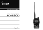
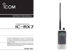
INSTRUCTION MANUAL
VHF/UHF FM TRANSCEIVER
iE91
FOREWORD
FEATURES
Thank you for purchase of this fine Icom product. We understand you have a choice of many different radios in the market place. Many hours of research and development went into
the design of your IC-E91, following Icom’s philosophy of
“technology first.”
❍ DV mode (Digital voice + Low-speed data
communication) operation is ready
– GPS receiver connection
– Text message and call sign exchange
The IC-E91 VHF/UHF FM TRANSCEIVER is designed with Icom’s
superior technology and craftsmanship combining traditional
analog technologies with the new digital D-STAR technologies for a balanced packaged.
With proper care, this product should provide you with years
of trouble-free operation. We want to take a couple of moments of your time to thank you for making your IC-E91 your
radio of choice, and hope you agree with Icom’s philosophy of
“technology first.”
(Optional UT-121 DIGITAL UNIT is required.)
❍ Simple band scope
❍ Dualwatch operation
❍ Optional PC remote control
IMPORTANT
READ ALL INSTRUCTIONS carefully and completely
before using the transceiver.
EXPLICIT DEFINITIONS
WORD
DEFINITION
Personal injury, fire hazard or electric shock
R WARNING!
may occur.
CAUTION
NOTE
i
SAVE THIS INSTRUCTION MANUAL— This instruction manual contains important operating instructions for
the IC-E91.
Equipment damage may occur.
Recommended for optimum use. No risk of
personal injury, fire or electric shock.
Icom, Icom Inc. and the
logo are registered trademarks of Icom
Incorporated (Japan) in the United States, the United Kingdom, Germany, France, Spain, Russia and/or other countries.
PRECAUTIONS
RWARNING RF EXPOSURE! This device emits
Radio Frequency (RF) energy. Caution should be observed
when operating this device. If you have any questions regarding RF exposure and safety standards please refer to the
Federal Communications Commission Office of Engineering
and Technology’s report on Evaluating Compliance with FCC
Guidelines for Human Radio Frequency Electromagnetic
Fields (OET Bulletin 65)
RWARNING! NEVER hold the transceiver so that the
antenna is very close to, or touching exposed parts of the
body, especially the face or eyes, while transmitting. The
transceiver will perform best if the microphone is 5 to 10 cm
away from the lips and the transceiver is vertical.
RWARNING! NEVER operate the transceiver with a
earphone, headphones or other audio accessories at high
volume levels. Hearing experts advise against continuous
high volume operation. If you experience a ringing in your
ears, reduce the volume level or discontinue use.
RWARNING! NEVER operate the transceiver while
driving a vehicle. Safe driving requires your full attention—
anything less may result in an accident.
NEVER connect the transceiver to a power source of more
than 16 V DC. This will ruin the transceiver.
NEVER connect the transceiver to a power source using
reverse polarity. This will ruin the transceiver.
NEVER expose the transceiver to rain, snow or any liquids.
The transceiver may be damaged.
NEVER operate or touch the transceiver with wet hands.
This may result in an electric shock or damage the transceiver.
DO NOT operate the transceiver near unshielded electrical blasting caps or in an explosive atmosphere.
DO NOT push the PTT when not actually desiring to transmit.
BE CAREFUL! The transceiver will become hot when operating it continuously for long periods.
AVOID using or placing the transceiver in direct sunlight or
in areas with temperatures below –20°C or above +60°C.
Place the unit in a secure place to avoid inadvertent use by
children.
AVOID the use of chemical agents such as benzine or alcohol when cleaning, as they can damage the transceiver’s
surfaces.
1
2
3
4
5
6
7
8
9
10
11
12
13
14
15
16
17
18
19
ii
TABLE OF CONTENTS
FOREWORD …………………………………………………………… i
EXPLICIT DEFINITIONS ……………………………………………… i
FEATURES ……………………………………………………………… i
IMPORTANT …………………………………………………………… i
PRECAUTIONS ……………………………………………………… ii
TABLE OF CONTENTS ……………………………………………… iii
SUPPLIED ACCESSORIES ………………………………………… v
1
ACCESSORY ATTACHMENT ………………………………… 1
■ Antenna ………………………………………………………… 1
■ Belt clip ………………………………………………………… 1
■ Handstrap ……………………………………………………… 1
■ Battery pack …………………………………………………… 1
2
PANEL DESCRIPTION ……………………………………… 2–7
■ Front, top and side panels …………………………………… 2
■ Function display ……………………………………………… 6
3
BATTERY CHARGING ……………………………………… 8–13
■ Caution ………………………………………………………… 8
■ Regular charging ……………………………………………… 10
■ Rapid charging ……………………………………………… 11
■ Optional battery case ………………………………………… 12
■ Battery information …………………………………………… 12
■ External DC power operation ……………………………… 13
4
iii
FREQUENCY AND CHANNEL SETTING ……………… 14–19
■ Main band selection ………………………………………… 14
■ Mode selection ……………………………………………… 15
■ Operating band selection …………………………………… 16
■ Setting a tuning step ………………………………………… 18
■ Setting a frequency …………………………………………… 18
5
BASIC OPERATION ……………………………………… 20–28
■ Receiving ……………………………………………………… 20
■ Setting audio volume ………………………………………… 20
■ Setting squelch level ………………………………………… 21
■ Operating mode selection …………………………………… 21
■ Monitor function ……………………………………………… 22
■ Attenuator function …………………………………………… 22
■ Band scope …………………………………………………… 23
■ Transmitting …………………………………………………… 24
■ Transmit power selection …………………………………… 24
■ Lock function ………………………………………………… 25
■ Dualwatch operation ………………………………………… 25
■ TV channel operation ………………………………………… 28
6
REPEATER AND DUPLEX OPERATIONS ……………… 29–33
■ General ………………………………………………………… 29
■ Accessing a repeater ………………………………………… 30
■ Duplex operation ……………………………………………… 32
■ 1750 Hz tone ………………………………………………… 33
7
DV MODE OPERATION
(Optional UT-121 is required) ……………………………… 34–63
■ Digital mode operation ……………………………………… 34
■ Call sign programming ……………………………………… 34
■ Digital voice mode operation ………………………………… 38
■ About D-STAR system ……………………………………… 40
■ Digital repeater operation …………………………………… 41
■ Received call sign …………………………………………… 46
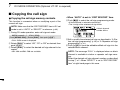
■ Copying the call sign ………………………………………… 48
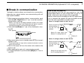
■ Break-in communication …………………………………… 51
■ Message operation …………………………………………… 52
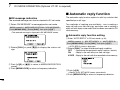
■ Automatic reply function ……………………………………… 54
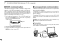
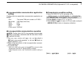
■ EMR communication ………………………………………… 56
■ Low-speed data communication …………………………… 56
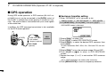
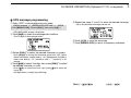
■ GPS operation ………………………………………………… 58
■ Other functions for DV mode operation …………………… 62
8
9
MEMORY/CALL CHANNELS …………………………… 64–73
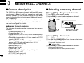
■ General description ………………………………………… 64
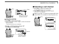
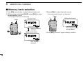
■ Selecting a memory channel ………………………………… 64
■ Selecting a call channel ……………………………………… 65
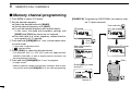
■ Memory channel programming ……………………………… 66
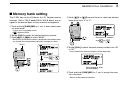
■ Memory bank setting ………………………………………… 67
■ Memory bank selection ……………………………………… 68
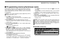
■ Programming memory/bank/scan name …………………… 69
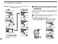
■ Selecting memory/bank name indication ………………… 70
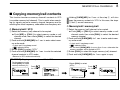
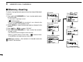
■ Copying memory/call contents ……………………………… 71
■ Memory clearing ……………………………………………… 72
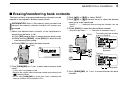
■ Erasing/transferring bank contents ………………………… 73
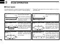
SCAN OPERATION ………………………………………… 74–81
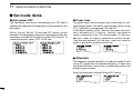
■ Scan types …………………………………………………… 74
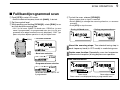
■ Full/band/programmed scan ………………………………… 75
■ Scan edges programming …………………………………… 76
■ Memory scan ………………………………………………… 77
■ Memory bank scan …………………………………………… 78
■ Skip channel/frequency setting ……………………………… 79
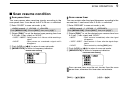
■ Scan resume condition ……………………………………… 81
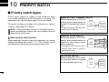
10 PRIORITY WATCH ………………………………………… 82–84
■ Priority watch types ………………………………………… 82
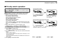
■ Priority watch operation ……………………………………… 83
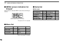
11 MENU SCREEN OPERATION ………………………… 85–102
■ General ………………………………………………………… 85
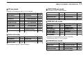
■ MENU screen indication for B band ………………………… 86
■ Menu list ……………………………………………………… 86
■ Items list ……………………………………………………… 86
■ Set mode items ……………………………………………… 88
■ DV set mode items …………………………………………… 92
■ Scan set mode items ………………………………………… 96
■ DUP/TONE set mode items ………………………………… 97
■ Display set mode items ……………………………………… 99
■ Sounds set mode items …………………………………… 102
12 OTHER FUNCTIONS …………………………………… 103–117
■ Programming a DTMF code ……………………………… 103
■ Transmitting a DTMF code ………………………………… 104
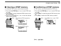
■ Clearing a DTMF memory ………………………………… 105
■ Confirming a DTMF memory ……………………………… 105
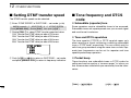
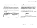
■ Setting DTMF transfer speed ……………………………… 106
■ Tone frequency and DTCS code ………………………… 106
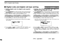
■ Digital code and digital call sign setting ………………… 108
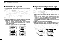
■ Tone/DTCS squelch ………………………………………… 110
■ Digital code/digital call sign squelch ……………………… 110
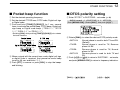
■ Pocket beep function ……………………………………… 111
■ DTCS polarity setting ……………………………………… 111
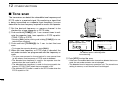
■ Tone scan …………………………………………………… 112
■ Beep tones …………………………………………………… 113
■ Dial speed acceleration …………………………………… 113
■ Key lock effect ……………………………………………… 113
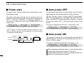
■ Power save ………………………………………………… 114
■ Auto power OFF …………………………………………… 114
■ Auto power ON ……………………………………………… 114
iv
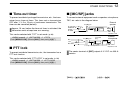
■ Time-out timer ……………………………………………… 115
■ PTT lock ……………………………………………………… 115
■ [MIC/SP] jacks ……………………………………………… 115
■ Cloning function …………………………………………… 116
■ Resetting …………………………………………………… 117
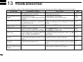
13 TROUBLESHOOTING ………………………………………… 118
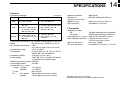
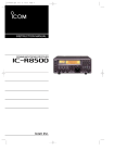
14 SPECIFICATIONS ……………………………………… 119–120
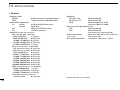
15 OPTIONS ………………………………………………… 121–123
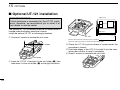
■ Optional UT-121 installation ……………………………… 122
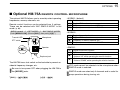
■ Optional HM-75A REMOTE CONTROL MICROPHONE ……… 123
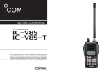
SUPPLIED ACCESSORIES
The following accessories are supplied with the transceiver.
q Hand strap ………………………………………………… 1
w Antenna …………………………………………………… 1
e Battery pack* ……………………………………………… 1
r Battery charger* …………………………………………… 1
t Belt clip (with screws) ………………………………… 1 set
*Not supplied with some versions.
16 CE ………………………………………………………… 124–125
q
w
e
t
v
r
1
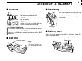
ACCESSORY ATTACHMENT
■ Antenna
Jack cover
■ Handstrap
Insert the supplied antenna into the
antenna connector and screw down
the antenna as shown at left.
1
Slide the handstrap through the loop
on the top of the belt clip as illustrated
at left to facilitate carrying the
transceiver.
NEVER carry the transceiver by holding the antenna.
KEEP the jack cover attached when
jack is not in use to protect the connector from dust and moisture.
✔ For your information
Third-party antennas may increase transceiver performance. An optional AD-92SMA ANTENNA CONNECTOR
ADAPTER is available to connect an antenna with a BNC
connector.
■ Belt clip
Supplied screws*
Handstrap
■ Battery pack
Attach the Li-ion battery pack (BP-217) or battery case (BP216) as illustrated below.
• Charge the Li-ion battery pack before use. (pgs. 10, 11)
Battery pack/
Battery case
*NOTE:
USE the supplied screws
only. Using screws longer than specified could
damage the transceiver.
q
w
Latch
1
2
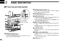
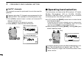
PANEL DESCRIPTION
■ Front, top and side panels
w TX/RX INDICATOR [TX/RX] (p. 24)
Lights green while receiving a signal or when the squelch
is open; lights red while transmitting.
!7
q
!4
!5
!3
r SQUELCH KEY [SQL]
➥ Push and hold to open the squelch temporarily and
monitor the operating frequency. (p. 22)
➥ While pushing and holding this key, rotate [DIAL] to adjust the squelch level. (p. 21)
Internal microphone
t MENU/LOCK KEY [MENU/LOCK]
➥ Push to toggle menu screen indication ON and OFF.
(p. 85)
➥ Push and hold for 1 sec. to toggle the lock function ON
and OFF. (p. 25)
w
e
r
t
y
u
i
e PTT SWITCH [PTT] (p. 24)
Push and hold to transmit, release to receive.
!6
Function display
Speaker
!2
!1
!0
o
q ANTENNA CONNECTOR (p. 1)
Connects the supplied antenna.
• An optional AD-92SMA adapter (p. 121) is available for connecting an antenna with a BNC connector.
y POWER KEY [PWR]
Push and hold for 1 sec. to turn the transceiver power ON
and OFF.
u MAIN/DUAL KEY [MAIN/DUAL]
➥ Push to select the main band between A and B bands.
(p. 26)
➥ Push and hold for 1 sec. to toggle the dualwatch function ON and OFF. (p. 25)
i KEYPAD (pgs. 4, 5)
2
PANEL DESCRIPTION
2
o CALL/RX➝CS KEY [CALL]/[RX➝CS](CALL)
➥ Push to select the call channel/TV channel. (p. 16)
➥ During DV mode operation, push and hold for 1 sec. to
set the received call signs (station and repeaters) for operation. (p. 47)
➥ Enters or sends the DTMF code “C.” (pgs. 103, 104)
!3 EXTERNAL DC IN JACK [DC IN]
➥ Connects the supplied wall charger, BC-167A/D, to
charge the attached battery pack. (p. 10)
➥ Connect an external DC power supply through the optional CP-19R or OPC-254L for external DC operation.
(p. 13)
!0 MEMORY/SELECT MEMORY WRITE KEY
[MR]/[S.MW](MR)
➥ Push to select memory mode. (p. 15)
➥ During memory mode operation, push to toggle between memory and memory bank mode. (p. 68)
➥ Push and hold for 1 sec. to enter select memory write
mode. (p. 64)
➥ Enters or sends the DTMF code “B.” (pgs. 103, 104)
!4 DATA JACK [DATA]
Connects a PC through the optional data communication
cable, OPC-1529R, for low-speed data communication or
control the transceiver remotely using the optional RS-91
(OPC-1529R is supplied). (p. 56)
!1 VFO/MHz KEY [VFO]/[MHz](VFO)
➥ Push to toggle select VFO mode. (p. 15)
➥ During VFO mode operation, push and hold for 1 sec. to
select and toggle 1 MHz and 10 MHz tuning steps
(p. 18)
➥ Enters or sends the DTMF code “A.” (pgs. 103, 104)
!6 CONTROL DIAL [DIAL]
➥ Rotate to tune the operating frequency. (p. 18)
➥ During memory mode, rotate to select the memory
channel. (pgs. 15, 64)
➥ While pushing and holding [BAND], selects the operating band in VFO mode. (p. 18)
➥ While scanning, changes the scanning direction. (p. 75)
➥ While pushing and holding [SQL], sets the squelch
level. (p. 21)
➥ While pushing and holding [BAND], selects the programmed bank in memory mode. (p. 68)
!2 BAND KEY [BAND]
➥ During VFO mode operation, push to select an operating frequency band. (pgs. 16, 17)
➥ During memory bank mode, push to select a memory
bank. (p. 68)
➥ Enters or sends the DTMF code “D.” (pgs. 103, 104)
2
!5 VOLUME CONTROL [VOL]
Rotate to adjust the audio output level. (p. 20)
!7 EXTERNAL SPEAKER/MICROPHONE JACK [MIC/SP]
Connect an optional speaker-microphone or headset, if desired.
See page 121 for a list of available options.
3
2
PANEL DESCRIPTION
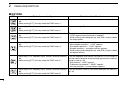
D KEYPAD
KEY
Pushed momentarily
Pushed and held for 1 sec.
• Inputs digit ‘1’ for frequency input, memory channel selection, • Displays the simple band scope for a single sweep. (p. 23)
etc.
• While pushing [PTT], this key sends the DTMF code “1.”
• Inputs digit ‘2’ for frequency input, memory channel selection, • Starts a scan. (p. 75)
etc.
• While pushing [PTT], this key sends the DTMF code “2.”
• Inputs digit ‘3’ for frequency input, memory channel selection, • Toggles the transmit output power between high and low. (p. 24)
- “LOW” appears when low power is selected.
etc.
- While pushing and holding this key, with [DIAL] rotation selects
• While pushing [PTT], this key sends the DTMF code “3.”
the output power.
• Inputs digit ‘4’ for frequency input, memory channel selection, • Activates the following duplex functions in order.
- Minus duplex operation— “–DUP” appears.
etc.
- Plus duplex operation— “+DUP” appears.
• While pushing [PTT], this key sends the DTMF code “4.”
- Simplex operation— no duplex indicator appears.
- While pushing and holding this key, with [DIAL] rotation selects
the duplex function.
• Inputs digit ‘5’ for frequency input, memory channel selection, • Turn the frequency skip function ON and OFF in VFO mode, or
set the memory channel as the following skip channel in memory
etc.
mode in order (p. 79).
• While pushing [PTT], this key sends the DTMF code “5.”
- Skip channel— “SKIP” appears.
- Frequency skip channel— “PSKIP” appears.
- Non-skip channel— no skip indicator appears.
• Inputs digit ‘6’ for frequency input, memory channel selection, • Turn the memory name or bank name indication ON and OFF.
(p. 70)
etc.
• While pushing [PTT], this key sends the DTMF code “6.”
4
PANEL DESCRIPTION
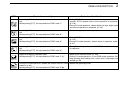
KEY
Pushed momentarily
2
Pushed and held for 1 sec.
• Inputs digit ‘7’ for frequency input, memory channel selection, • During FM/FM-N mode operation, selects repeater tone, tone
squelch, DTCS squelch and no tone operation in sequence.
etc.
(p. 110)
• While pushing [PTT], this key sends the DTMF code “7.”
• During DV mode operation, selects digital call sign, digital code
and no tone operation in sequence. (p. 110)
2
• Inputs digit ‘8’ for frequency input, memory channel selection, • Selects tuning step selection. (p. 18)
etc.
• While pushing [PTT], this key sends the DTMF code “8.”
• Inputs digit ‘9’ for frequency input, memory channel selection, • During FM/FM-N mode operation, starts tone scan function.
(p. 112)
etc.
• During DV mode operation, selects break-in operation mode.
• While pushing [PTT], this key sends the DTMF code “9.”
(p. 51)
• Inputs digit ‘0’ for frequency input, memory channel selection, • During DV mode operation, set “CQCQCQ” for station’s call sign
for operation.
etc.
• While pushing [PTT], this key sends the DTMF code “0.”
• Inputs MHz digit for frequency input.
• While pushing [PTT], this key sends the DTMF code “F (#).”
• Select DTMF memory mode. (p. 103)
• During DV mode operation, to turn EMR mode operation ON,
keep pushing and holding until 3 short and 1 long beeps are
emitted. (p. 56)
• During DV mode operation, selects the record track for voice • Selects the operating mode.
memory. (p. 62)
• While pushing [PTT], this key sends the DTMF code “E (✱).”
5
2
PANEL DESCRIPTION
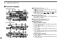
■ Function display
• Single band indication
q
!7
!6
!5
!4
!3
w
e
r
t y
-DUP DSQL
DV
PRIO
B
EMR
439 706 25
MemoName PSKIP
000
µ
LOW
ATT
u
i
o
!0
• Dualwatch indication
!6
i
e
o
PS
88 100
25 PRIO
!7
q
y
!6
w
!1
r
µ
!4
000
!8
e
-DUP DTCS
i
!7
!3
6
!1
!4
t
!0
o
PS
PRIO
439 70675 µ
000
!2
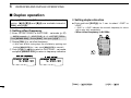
w DUPLEX INDICATORS (p. 29)
“+DUP” appears when plus duplex, “–DUP” appears when
minus duplex is selected.
e PRIORITY WATCH INDICATOR (p. 83)
Appears when priority watch is in use.
!1
!2
q BATTERY INDICATOR (pgs. 10, 12)
➥“
” (battery indicators) appear when the Li-ion battery pack is attached.
➥ “ ” appears when the battery pack must be charged.
➥ The indicators show “
,” “
” and “
” in sequence while charging the attached battery pack.
!8
!0
r TONE INDICATORS
• While operating in FM mode;
➥ “TONE” appears while the subaudible tone encoder is
in use. (pgs. 29, 106)
➥ “TSQL” appears while the tone squelch function is in
use. (p. 110)
➥ “DTCS” appears while the DTCS squelch function is in
use. (p. 110)
➥ “S” appears with the “TSQL” or “DTCS” indicator
while the pocket beep function (with CTCSS or DTCS) is
in use. (p. 111)
• While operating in DV mode;
➥ “DSQL” appears while the call sign squelch function is
in use. (p. 110)
➥ “CSQL” appears while the digital code squelch function
is in use. (p. 110)
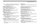
PANEL DESCRIPTION
➥ “S” appears with the “DSQL” or “CSQL” indicator
while the pocket beep function (with digital call sign or digital code squelch) is in use. (p. 111)
t KEY LOCK INDICATOR (pgs. 25, 113)
Appears when the key lock function is activated.
y AUTO POWER OFF INDICATOR (p. 88)
Appears when the auto power OFF function is in use.
u EMR MODE INDICATOR (p. 56)
Appears when the EMR mode operation is selected.
i FREQUENCY READOUT
Displays a variety of information, such as operating frequency, set mode contents, memory names.
• The decimal point blinks during scan.
o SKIP INDICATORS (pgs. 79, 80)
➥ “SKIP” appears when the selected memory channel is
set as a skip channel.
➥ “P SKIP” appears when the displayed frequency is set
as a skip frequency.
!0 MEMORY CHANNEL NUMBER INDICATOR
➥ Shows the selected memory channel number. (pgs. 64,
65)
➥ “C” appears when the call channel is selected. (pgs. 16,
65)
➥ “TV” appears when the TV channel is selected.
(pgs. 16, 28)
2
!1 S/RF METER
➥ Shows the relative signal strength while receiving signals.
➥ Shows the output power level while transmitting. (p. 24)
2
!2 ATTENUATOR INDICATOR (p. 22)
Appears when the RF attenuator is in use.
!3 LOW POWER INDICATOR (p. 24)
➥ “LOW” appears when low power is selected.
➥ No indicator appears when high power is selected.
!4 MEMORY INDICATOR (p. 64)
Appears when memory mode is selected.
!5 NAME INDICATOR (p. 70)
During memory mode operation, the programmed memory
or memory bank name is displayed.
!6 MAIN BAND INDICATOR (p. 14)
Shows which operating band, “A” or “B,” is selected for the
main band.
!7 OPERATING MODE INDICATOR (p. 21)
Shows the selected operating mode.
• DV, FM, FM-N, WFM and AM are available, depending on operating band.
!8 SIMPLE BAND SCOPE INDICATOR (p. 23)
When the simple band scope function is in use, shows the
band conditions.
7
3
BATTERY CHARGING
■ Caution
Misuse of Lithium-ion batteries may result in the following hazards: smoke, fire, or the battery may rupture.
Misuse can also cause damage to the battery or degradation of battery performance.
• R DANGER! Use and charge only specified Icom battery
packs with Icom radios. Only Icom battery packs are tested
and approved for use with Icom radios. Using third-party or
counterfeit battery packs may cause smoke, fire, or cause
the battery to burst.
D Battery caution
• R DANGER! DO NOT hammer or otherwise impact the battery. Do not use the battery if it has been severely impacted
or dropped, or if the battery has been subjected to heavy
pressure. Battery damage may not be visible on the outside
of the case. Even if the surface of the battery does not show
cracks or any other damage, the cells inside the battery may
rupture or catch fire.
• R DANGER! NEVER use or leave battery pack in areas
with temperatures above +60˚C. High temperature buildup
in the battery, such as could occur near fires or stoves, inside a sun heated car, or in direct sunlight may cause the
battery to rupture or catch fire. Excessive temperatures may
also degrade battery performance or shorten battery life.
8
• R DANGER! DO NOT expose the battery to rain, snow,
seawater, or any other liquids. Do not charge or use a wet
battery. If the battery gets wet, be sure to wipe it dry before
using. The battery is not waterproof.
• R DANGER! NEVER incinerate an used battery pack since
internal battery gas may cause it to rupture, or may cause
an explosion.
• R DANGER! NEVER solder the battery terminals, or
NEVER modify the battery pack. This may cause heat generation, and the battery may burst, emit smoke or catch fire.
• R DANGER! Use the battery only with the transceiver for
which it is specified. Never use a battery with any other
equipment, or for any purpose that is not specified in this instruction manual.
• R DANGER! If fluid from inside the battery gets in your
eyes, blindness can result. Rinse your eyes with clean
water, without rubbing them, and see a doctor immediately.
• WARNING! Immediately stop using the battery if it emits an
abnormal odor, heats up, or is discolored or deformed. If any
of these conditions occur, contact your Icom dealer or distributor.
• WARNING! Immediately wash, using clean water, any part
of the body that comes into contact with fluid from inside the
battery.
BATTERY CHARGING
• WARNING! NEVER put the battery in a microwave oven,
high-pressure container, or in an induction heating cooker.
This could cause a fire, overheating, or cause the battery to
rupture.
• CAUTION! Always use the battery within the specified temperature range, –20˚C to +60˚C. Using the battery out of its
specified temperature range will reduce the battery’s performance and battery life.
• CAUTION! Shorter battery life could occur if the battery is
left fully charged, completely discharged, or in an excessive
temperature environment (above +50˚C) for an extended
period of time. If the battery must be left unused for a long
time, it must be detached from the radio after discharging.
You may use the battery until the battery indicator shows
half-capacity, then keep it safely in a cool dry place with the
temperature between –20˚C to +20˚C.
3
D Charging caution
• R DANGER! NEVER charge the battery pack in areas with
extremely high temperatures, such as near fires or stoves,
inside a sun heated car, or in direct sunlight. In such environments, the safety/protection circuit in the battery will activate, causing the battery to stop charging.
3
• WARNING! DO NOT charge or leave the battery in the battery charger beyond the specified time for charging. If the
battery is not completely charged by the specified time, stop
charging and remove the battery from the battery charger.
Continuing to charge the battery beyond the specified time
limit may cause a fire, overheating, or the battery may rupture.
• WARNING! NEVER insert the transceiver (battery attached
to the transceiver) into the charger if it is wet or soiled. This
could corrode the battery charger terminals or damage the
charger. The charger is not waterproof.
• CAUTION! DO NOT charge the battery outside of the specified temperature range: 0˚C to +35˚C. Icom recommends
charging the battery at +20˚C. The battery may heat up or
rupture if charged out of the specified temperature range.
Additionally, battery performance or battery life may be reduced.
9
3
BATTERY CHARGING
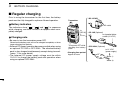
■ Regular charging
Prior to using the transceiver for the first time, the battery
pack must be fully charged for optimum life and operation.
• BC-167A/D
Transceiver
D Battery indicators
The indicators show “
,” “
” and “
” in sequence
while charging, and both indicators disappear when completely charged.
to AC outlet
to
[DC IN]
D Charging note
• CP-19R (Optional)
to cigarette lighter
socket (12 V DC)
• Be sure to turn the transceiver power OFF.
Otherwise the battery pack will not be charged completely or takes
longer charging time periods.
• External DC power operation becomes possible when using
an optional CP-19R or OPC-254L. The attached battery
pack is also charged simultaneously, except during transmit.
(see p. 11 for more details)
• The external DC power supply voltage must be within
10–16 V to charge the battery pack and operation when
using an optional OPC-254L.
10
Turn power OFF while
charging the battery
pack.
• Charging time period:
Approx. 6 hours
• OPC-254L (Optional)
to 12 V DC
(power supply)
Black: _
White: +
BATTERY CHARGING
3
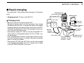
■ Rapid charging
The optional BC-139 provides rapid charging of the battery
pack.
• Charging period: 2.5 hours (with BP-217)
D Charging note
• Be sure to turn the transceiver power OFF.
Detach the battery pack from the transceiver then charge
the battery pack by itself, or charge the battery with regular
charging when the transceiver power cannot be turned OFF.
Otherwise the battery pack will not be charged (charging indicator on the BC-139 blinks orange).
• The desktop charger, BC-139, can only be charged BP-217.
Other types of rechargeable battery, Ni-Cd or Ni-MH, cannot be charged.
• If the charging indicator blinks orange, there may be a problem with the battery pack (or charger). Reinsert the battery
pack or contact your dealer.
• The optional CP-19R and OPC-254L can be used instead
of the supplied AC adapter (BC-123). Connect one of these
to the [AC ADAPTER] jack in this case.
Transceiver
(with battery pack)
Battery pack
3
Turn power OFF.
to AC outlet
Check the
orientation.
A
Adapter (supplied
with BC-139)
Charging
terminal
BC-123
(supplied
with BC-139)
to [AC ADAPTER]
Charging indicator
Charging : Orange
Finished : Green
BC-139 (optional)
Desktop charger
11
3
BATTERY CHARGING
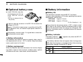
■ Optional battery case
➥ Install 2 R6 (AA) size alkaline batteries into the optional BP-216 BATTERY
CASE.
• Be sure to observe the correct polarity.
■ Battery information
D Battery life
The transceiver operates with the BP-217 as follows.
However, when operating in DV mode, operating time may be
shortened by one-half hour.
• VHF band : Approx. 5 hours
• UHF band : Approx. 4.5 hours
(Tx: Rx: Stand-by=1: 1: 8)
A built-in step-up convertor in the BP-216 increases the
voltage to 5 V DC.
Approx. 100 mW of output power is possible with the BP216 operation. Also, no transmit output power selection is
available.
Keep battery contacts clean. It’s a good idea to clean battery terminals once a week.
D Battery information
The batteries may seem to have low capacity when used in
low temperatures such as –10°C or below. Keep the battery
case or pack warm in this case.
D Battery replacement
When the batteries become exhausted, the function display
may blink or have a lower contrast. In these cases, replace
all batteries with new, same brand, alkaline batteries.
12
Even when the transceiver power is OFF, a slight current
still flows in the circuits. Remove the battery pack or case
from the transceiver when not using it for a long time. Otherwise, the battery pack or installed batteries will become
exhausted.
D Battery indicator
The battery indicator, “
,” appears only when the BP-217
is attached to the transceiver.
The battery indicator does not appear when turning power
ON after the charging is completed without disconnecting
the battery charger or external DC power.
Indication
Battery condition
The battery has ample capacity.
The battery is nearing exhaustion. Charging is necessary.
BATTERY CHARGING
3
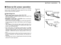
■ External DC power operation
An optional cigarette lighter cable CP-19R; for 12 V cigarette
lighter socket) or external DC power cable (OPC-254L) can be
used for external power operation.
D Operating note
• Power supply range is between 10.0–16.0 V DC.
NEVER CONNECT OVER 16 V DC directly into the [DC IN]
jack of the transceiver.
• BE SURE to use CP-19R or OPC-254L when connecting a
regulated 12 V DC power supply.
Use an external DC-DC converter to connect the transceiver
through optional CP-19R or OPC-254L to a 24 V DC power
source.
• The voltage of the external power supply must be within
10–16 V DC when using either CP-19R or OPC-254L, otherwise, use the battery pack.
• Up to 5 W (approx.) of maximum output power is provided
with the external DC power operation, however, when the
supplied voltage exceeds 14 V, the built-in protection circuit
activates to reduce the transmit output power to 0.5 W (approx.).
• Disconnect the power cables from the transceiver when not
using it. Otherwise, the vehicle battery will become exhausted.
• The power save function is deactivated automatically during
external DC power operation.
Transceiver
• CP-19R (Optional)
to cigarette lighter
socket (12 V DC)
3
to
[DC IN]
• OPC-254L (Optional)
to 12 V DC
(power supply)
Black: _
White: +
13
4
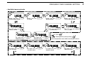
FREQUENCY AND CHANNEL SETTING
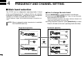
■ Main band selection
The IC-E91 has two independent operating bands; A band
(VFO A) and B band (VFO B). A band (VFO A) can operate
0.495 MHz to 999.990 MHz*, and B band (VFO B) can operate
118 MHz to 174 MHz* and 350 MHz to 470 MHz*.
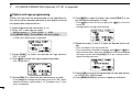
D How to change the main band
➥ Push [MAIN/DUAL] to toggle between A and B band.
➥ Push and hold [MAIN/DUAL] for 1 sec. to turn the dualwatch operation ON and OFF.
*Some frequency ranges are blocked according to transceiver version.
• While in dualwatch operation, the display indicates A band in the
upper half and B band in the lower half.
➥ During dualwatch operation, push [MAIN/DUAL] to select
A band or B band as the main operating band alternately.
NOTE: When in dualwatch mode, transmission is available
from the MAIN band only.
Single band operation
Dualwatch operation
• Selecting A band
• Selecting upper side as main band
+DUP DTCS
FM
PRIO WX EMR
A
145 000 25
MemoName P
LOW
ATT
µ
+DUP DTCS
W PS
FM
+DUP DTCS
W PS
145 000 25 µPRIO000
SKIP
EM
430 00050 µPRIO000
000
FM
Push
Push
Push
for 1 sec.
• Selecting B band
+DUP DTCS
FM
PRIO WX EMR
B
430 000 25
MemoName P
LOW
ATT
14
µ
SKIP
000
• Selecting lower side as main band
+DUP DTCS
W PS
FM
+DUP DTCS
W PS
145 000 25 µPRIO000
EM
430 00050 µPRIO000
FM
FREQUENCY AND CHANNEL SETTING
4
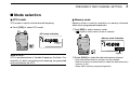
■ Mode selection
D VFO mode
D Memory mode
VFO mode is used to set the desired frequency.
Memory mode is used for operation on memory channels
which store programmed frequencies.
➥ Push [VFO] to select VFO mode.
4
q Push [MR] to select memory mode.
µ
• “µ
” appears when memory mode is selected.
• VFO mode indication
+DUP DTCS
FM
PRIO WX EMR
A
145 000 25
MemoName P
LOW
ATT
µ
SKIP
000
• Memory mode indication
+DUP DTCS
FM
PRIO WX EMR
A
145 000 25
MemoName P
LOW
ATT
µ
SKIP
000
Appear
What is VFO?
VFO is an abbreviation of Variable Frequency Oscillator. Frequencies for both transmitting and receiving are generated
and controlled by the VFO.
w Rotate [DIAL] to select the desired memory channel.
• Only programmed memory channels can be selected.
• Enter the memory channel directly to select the desired memory
channel. (p. 64)
• See p. 66 for memory programming details.
15
4
FREQUENCY AND CHANNEL SETTING
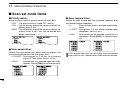
D Call/TV* channels
Call channels are used for quick recall of most-often used frequencies.
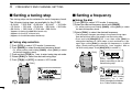
■ Operating band selection
*Appears only when TV channels are programmed via the
optional RS-91. Also available for A band operation only.
The transceiver can receive the AM broadcast, HF bands,
50 MHz, FM broadcast, VHF air, 144 MHz, 300 MHz,
400 MHz or 800 MHz* bands. (Some bands are not selectable
for B band operation. See next page for details.)
qPush [CALL] several times to select call channels/TV
channels (A band only).
➥ In VFO mode, push [BAND] several times to select the desired frequency band.
• Call/TV channels can be selected in sequence.
w Rotate [DIAL] to select the desired channel.
• Call channel indication
[DIAL]
+DUP DTCS
FM
PRIO WX EMR
A
145 000 25
MemoName P
LOW
ATT
µ
SKIP
• If the other than VFO mode is selected, such as a memory channel/call channel/TV channel, push [VFO] to select VFO mode
first, then push [BAND] to select the desired band.
➥ While pushing and holding [BAND], rotating [DIAL] also
selects frequency band.
[DIAL]
C0
+DUP DTCS
FM
PRIO WX EMR
• TV channel indication
+DUP DTCS
WFM
PRIO WX EMR
A
10 ch
MemoName P
LOW
ATT
µ
25
A
145 000 25
MemoName P
LOW
ATT
µ
SKIP
000
SKIP
TV
Available frequency bands are different depending on version. See the specification for details. (pgs. 119, 120)
*Some frequency ranges are blocked accordinto transceiver version.
16
FREQUENCY AND CHANNEL SETTING
• Available frequency bands
• A band
+DUP DTCS
AM
PRIO WX EMR
A
001 620
MemoName P
+DUP DTCS
AM
PRIO WX EMR
25
A
MemoName P
SKIP
AM broadcast band
005 000
25
SKIP
HF band
850 000
MemoName P
051 000
MemoName P
SKIP
145 000
A
MemoName P
SKIP
25
SKIP
144 MHz band
+DUP DTCS
FM
PRIO WX EMR
430 000
MemoName P
25
SKIP
+DUP DTCS
WFM
PRIO WX EMR
A
088 000 25
MemoName P
SKIP
FM broadcast band
+DUP DTCS
FM
PRIO WX EMR
25
800 MHz band
A
25
50 MHz band
+DUP DTCS
FM
PRIO WX EMR
A
+DUP DTCS
FM
PRIO WX EMR
A
+DUP DTCS
AM
PRIO WX EMR
A
118 000 25
MemoName P
SKIP
VHF air band
+DUP DTCS
FM
PRIO WX EMR
A
370 000 25
MemoName P
400 MHz band
300 MHz band
+DUP DTCS
AM
PRIO WX EMR
+DUP DTCS
FM
PRIO WX EMR
: Push
SKIP
: Rotating [DIAL] while pushing
Initial frequencies shown differ according to version.
• B band
A
B
118 000 25
MemoName P
VHF air band
SKIP
A
B
145 000 25
MemoName P
144 MHz band
SKIP
+DUP DTCS
FM
PRIO WX EMR
A
B
370 000 25
MemoName P
300 MHz band
SKIP
+DUP DTCS
FM
PRIO WX EMR
A
B
430 000 25
MemoName P
400 MHz band
SKIP
4
1
2
3
4
5
6
7
8
9
10
11
12
13
14
15
16
17
18
19
17
4
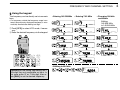
FREQUENCY AND CHANNEL SETTING
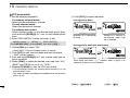
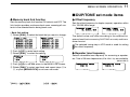
■ Setting a tuning step
■ Setting a frequency
The tuning step can be selected for each frequency band.
The following tuning steps are available for the IC-E91.
• 5.0 kHz* • 6.25 kHz* • 8.33 kHz† • 9.0 kHz‡ • 10.0 kHz
• 12.5 kHz • 15.0 kHz • 20.0 kHz • 25.0 kHz • 30.0 kHz
• 50.0 kHz • 100.0 kHz • 125.0 kHz • 200.0 kHz
q Push [VFO] to select VFO mode, if necessary.
w Select the desired frequency band with [BAND].
* Appears for below the 600 MHz bands only.
† Appears for the VHF air band only.
‡ Appears for the AM broadcast band only.
• Or, while pushing and holding [BAND], rotate [DIAL] to select
the desired frequency band.
e Rotate [DIAL] to select the desired frequency.
D Tuning step selection
q Push [VFO] to select VFO mode, if necessary.
w Push [BAND] to select the desired frequency band.
• Or, while pushing and holding [BAND], rotate [DIAL] to select
the desired frequency band.
e Push and hold [TS](8) for 1 sec. to enter tuning step set mode.
r Rotate [DIAL] to select the desired tuning step.
t Push [TS](8) (or [VFO]) to return to VFO mode.
[DIAL]
+DUP DTCS
FM
PRIO WX EMR
A
D Using the dial
145 000
25
• The frequency changes according to the preset tuning steps.
See the left-hand side of the page to set the tuning step.
• Push and hold [MHz](VFO) for 1 sec. then rotate [DIAL] to
change the frequency in 1 MHz steps, or push and hold for 1 sec.
again then rotate [DIAL] to change the frequency in 10 MHz
steps. (Each pushing and holding for 1 sec. toggles 1 MHz or
10 MHz tuning steps. Push [MHz](VFO) to cancel it.)
[DIAL]
+DUP DTCS
FM
PRIO WX EMR
A
145 000 25
[DIAL] changes the frequency according to the selected tuning step.
+DUP DTCS
FM
PRIO WX EMR
A
145 000 25
P SKIP
µ
SET-TS:5.0kHz
5 kHz tuning step
18
000
After pushing and holding
[MHz](VFO) for 1 sec.,
[DIAL] changes the frequency in 1 MHz/10 MHz steps.
FREQUENCY AND CHANNEL SETTING
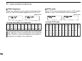
D Using the keypad
The frequency can be directly set via numeric
keys.
• If a frequency outside the frequency range is entered, the previously displayed frequency is automatically recalled after editing last digit.
qPush [VFO] to select VFO mode, if necessary.
w Enter the desired frequency via the keypad.
• Entering 145.520 MHz
+DUP DTCS
FM
PRIO WX
A
146 520 25
+DUP DTCS
FM
PRIO WX
A
146 520 25
+DUP DTCS
FM
PRIO WX
A
145 520 25
+DUP DTCS
FM
PRIO WX
A
145 520 25
+DUP DTCS
FM
PRIO WX
A
145 520 25
145 520
+DUP DTCS
FM
PRIO WX
A
730 000 25
• Changing 100 kHz
and below.
Editting
145.520 MHz
to 145.240 MHz
+DUP DTCS
FM
PRIO WX
A
790 000 25
+DUP DTCS
FM
PRIO WX
A
079 300 25
+DUP DTCS
FM
PRIO WX
A
079 300 25
+DUP DTCS
FM
PRIO WX
A
079 300 25
+DUP DTCS
FM
PRIO WX
+DUP DTCS
FM
PRIO WX
A
• Entering 79.3 MHz
25
A
079 300 25
• Editting to 684 kHz
+DUP DTCS
FM
PRIO WX
Depending on the tuning step setting, the 1
kHz digit may not acceptable as input. In
this case, enter “0” as 1 kHz digit, then rotate [DIAL] to set the desired frequency.
A
000 684 25
+DUP DTCS
FM
PRIO WX
A
145 240 25
+DUP DTCS
FM
PRIO WX
A
145 240 25
+DUP DTCS
FM
PRIO WX
A
145 240 25
+DUP DTCS
FM
PRIO WX
A
145 240 25
4
1
2
3
4
5
6
7
8
9
10
11
12
13
14
15
16
17
18
19
19
5
BASIC OPERATION
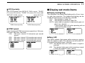
■ Receiving
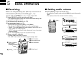
■ Setting audio volume
Make sure charged battery pack (BP-217) or brand new alkaline batteries (BP-216) are installed (pgs. 1, 12).
➥ Rotate [VOL] to adjust the audio level.
q Push and hold [PWR] for 1 sec. to turn power ON.
wRotate [VOL] to set the desired audio level.
• The frequency display shows the volume level while setting. See
the section at right for details.
e Set the receiving frequency. (p. 18)
r Set the squelch level. (p. 21)
• If squelch is closed, push and hold [SQL] to verify the audio
level.
• The display shows the volume level while setting.
+DUP DTCS
FM
PRIO WX EMR
[VOL]
A
145 000 25
MemoName P
• While pushing and holding [SQL], rotate [DIAL].
• The first click of [DIAL] indicates the current squelch level.
• “LEVEL 1” is loose squelch (for weak signals) and “LEVEL 9” is
tight squelch (for strong signals).
• “AUTO” indicates automatic level adjustment by a noise pulse
counting system.
• Push and hold [SQL] to open the squelch manually.
LOW
ATT
µ
SKIP
000
P SKIP
µ
000
VOL
Volume level indicator
tWhen a signal is received:
• Squelch opens and audio is output.
• The S/RF-meter shows the relative signal strength level.
e Set frequency
r Set squelch level
r Push for setting
the squelch
(Push to monitor)
P SKIP
µ
000
VOL
Minimum setting
(no audio)
w Set audio level
P SKIP
µ
000
VOL
Maximum setting
q [PWR]
20
e Select band
BASIC OPERATION
5
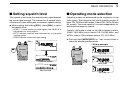
■ Setting squelch level
■ Operating mode selection
The squelch circuit mutes the received audio signal depending on the signal strength. The receiver has 9 squelch levels,
a continuously open setting and an automatic squelch setting.
Operating modes are determined by the modulation of the
radio signals. The transceiver has total 5 operating modes (A
band: FM, WFM and AM modes, B band FM, FM-N, AM and
DV modes). The mode selection is stored independently for
each band and memory channel.
➥ While pushing and holding [SQL], rotate [DIAL] to select
the squelch level.
• “LEVEL 1” is loose squelch (for weak signals) and “LEVEL 9” is
tight squelch (for strong signals).
• “AUTO” indicates automatic level adjustment by a noise pulse
counting system.
• “OPEN” indicates continuously open setting.
[DIAL]
+DUP DTCS
FM
PRIO WX EMR
A
145 000 25
MemoName P
LOW
ATT
µ
Typically, AM mode is used for the AM broadcast stations
(0.495–1.620 MHz) and air band (118–136.995 MHz), and
WFM is used for FM broadcast stations (76–107.9 MHz).
➥ Push and hold [MODE](REC) for 1 sec. several times to
select the desired operating mode.
• Display example
SKIP
000
FM
A
145 000 25
FM mode
P SKIP
µ
SQUELCH:AUTO
000
WFM
A
Automatic squelch
176 000 25
WFM mode
P SKIP
µ
000
SQUELCH:LEVEL9
Maximum level
AM
A
118 000 25
AM mode
1
2
3
4
5
6
7
8
9
10
11
12
13
14
15
16
17
18
19
21
5
BASIC OPERATION
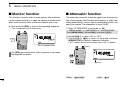
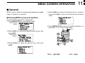
■ Monitor function
■ Attenuator function
This function is used to listen to weak signals without disturbing the squelch setting or to open the squelch manually even
when mute functions such as the tone squelch are in use.
The attenuator prevents a desired signal from distortion by
very strong signals near the desired frequency or when very
strong electric fields, such as from a broadcasting station, are
near your location. The attenuation is about 10 dB.
➥ Push and hold [SQL] to monitor the operating frequency.
q Enter “ATTENUATOR” in set mode. (p. 88)
MENU screen ➪ SET MODE ➪ ATTENUATOR
• The 1st segment of the S-meter blinks.
+DUP DTCS
FM
PRIO WX EMR
A
145 000 25
MemoName P
LOW
ATT
µ
SKIP
000
(Push [MENU/LOCK]) (Rotate [DIAL]†, then push [ï](5)†.)
w Rotate [DIAL]† to select “ON” or “OFF.”
Ω](4)) to return to set mode, and push
e Push [ï](5) (or [Ω
[MENU/LOCK] to return to frequency indication.
• “ATT” appears on the function display when “ON” is selected.
The 1st segment blinks
[DIAL]
+DUP DTCS
FM
PRIO WX EMR
A
The [SQL] key can be set to ‘sticky’ operation in set mode.
See page 89 for details.
145 000 25
MemoName P
LOW
ATT
µ
SKIP
000
Appears.
†[DIAL]
22
∫](2)/[√
√](8)
↔ [∫
≈](6)
[ï](5) ↔ [≈
BASIC OPERATION
5
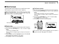
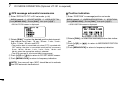
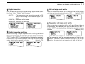
■ Band scope
The band scope function allows you to visually check a specified frequency range around the center frequency.
About the sweep steps: The specified tuning step in each
frequency band (in VFO mode) or programmed tuning step
(in memory mode) is used during sweep.
+DUP DTCS
FM
PRIO WX EMR
A
B
145 780 25
P SKIP
µ
Band scope indication
000
Sweep marker
D Continuous sweep
q Set the desired frequency as band scope center frequency.
w Push and hold [SCOPE](1) for 3 sec. to start continuous
sweep.
• 2 short beeps sound after 1 short and 1 long beeps.
• Signal conditions (strengths) appear starting from the center of
the range.
e Push and hold [SCOPE](1) for 1 sec. to cancel sweep.
• Pushing [SQL] also cancels sweep.
r Push [VFO] to return to normal operation.
+DUP DTCS
FM
PRIO WX EMR
A
B
145 780 25
P SKIP
D Single sweep
µ
000
q Set the desired frequency as band scope center frequency.
w Push and hold [SCOPE](1) for 1 sec. to start a single
sweep.
• 1 short and 1 long beeps sound.
• Signal conditions (strengths) appear starting from the center of
the range.
e Rotate [DIAL] to set the highlighted cursor to the desired
signal and set the frequency of the signal.
r Push [VFO] to return to normal operation.
The receive audio during sweeping can be muted in
sounds set mode. See page 102 for details.
1
2
3
4
5
6
7
8
9
10
11
12
13
14
15
16
17
18
19
23
5
BASIC OPERATION
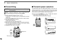
■ Transmitting
■ Transmit power selection
CAUTION: Transmitting without an antenna will damage
the transceiver.
NOTE: To prevent interference, listen on the channel before transmitting by pushing and holding [SQL].
q Set the operating frequency. (pgs. 18, 19)
• Transmission is available on the 144 MHz/430 MHz amateur
bands only.
• Select output power if desired. See the section at right for details.
w Push and hold [PTT] to transmit.
The transceiver has two output power levels to suit your operating requirements. Low output power during short-range
communications may reduce the possibility of interference to
other stations and will reduce current consumption.
➥ Push and hold [LOW](3) for 1 sec. to toggle the transmit
output power between High and Low.
• “LOW” appears when the low power is selected.
+DUP DTCS
FM
PRIO WX EMR
A
• Tx/Rx indicator lights red.
• S/RF meter shows the output power level.
145 000 25
MemoName P
e Speak into the microphone using your normal voice level.
• DO NOT hold the transceiver too close to your mouth or speak
too loudly. This may distort your speech.
LOW
ATT
µ
SKIP
000
Appears
r Release [PTT] to return to receive.
LOW
Low power transmission
Microphone
LOW
High power transmission
Tx/Rx indicator
24
BASIC OPERATION
5
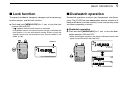
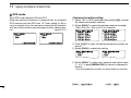
■ Lock function
■ Dualwatch operation
To prevent accidental frequency changes and unnecessary
function access, use the lock function.
Dualwatch operation monitors two frequencies simultaneously. The IC-E91 has two independent receiver circuits as A
band and B band (available frequency bands and operating mode
are different depending on bands).
➥ Push and hold [MENU/LOCK] for 1 sec. to turn the lock
function ON and OFF.
•“
” appears while the lock function is activated.
• The squelch control and volume control can be used while the
lock function is in use with default setting. Either or both the
squelch control and volume control can also be locked in set
mode. (p. 90)
Appears
D Dualwatch operation
➥ Push and hold [MAIN/DUAL] for 1 sec. to turn the dualwatch operation ON and OFF.
• While in dualwatch operation, the display indicates A band in the
upper half and B band in the lower half.
+DUP DTCS
FM
PRIO WX EMR
A
+DUP DTCS
FM
PRIO WX EMR
A
145 000 25
MemoName P
LOW
ATT
µ
145 000 25
MemoName P
SKIP
µ
000
+DUP DTCS
W PS
FM
+DUP DTCS
W PS
LOW
ATT
SKIP
000
145 000 25 µPRIO000
EM
430 00050 µPRIO000
FM
1
2
3
4
5
6
7
8
9
10
11
12
13
14
15
16
17
18
19
25
5
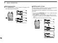
BASIC OPERATION
D Main band selection
➥ Push [MAIN/DUAL] to select A band or B band as the
main operating band alternately.
+DUP DTCS
W PS
FM
+DUP DTCS
W PS
145 000 25 µPRIO000
EM
430 00050 µPRIO000
FM
+DUP DTCS
W PS
145 000 25 µPRIO000
FM
+DUP DTCS
430 000
FM
W PS
50 PRIO EM
µ
D Setting audio volume
The audio level for dualwatch operation can be adjusted both
on A band and B band simultaneously (default).
This setting can be set separately for each band in sounds
set mode.
qPush and hold [MAIN/DUAL] for 1 sec. to enter the dualwatch operation, if necessary.
wRotate [VOL] to adjust the audio level for the main band.
• If squelch is closed, push and hold [SQL] to verify the audio
level.
• The display shows the volume level while setting.
[VOL]
+DUP DTCS
W PS
FM
+DUP DTCS
W PS
145 000 25 µPRIO000
000
EM
430 00050 µPRIO000
FM
+DUP DTCS
W PS
PRIO
145 000 25 µ
VOL
+DUP DTCS
000
W PS
EM
430 00075 µPRIO000
FM
Setting for A band (upper side)
W PS
+DUP DTCS
145 00025 µPRIO000
FM
+DUP DTCS
W PS
PRIO EM
430 000 75 µ
VOL
26
000
Setting for B band (lower side)
BASIC OPERATION
5
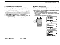
D Volume setting for dualwatch
D Setting squelch level
The volume setting for dualwatch can be set for both bands
simultaneously or for each band separately in set mode.
qPush and hold [MAIN/DUAL] for 1 sec. to enter the dualwatch operation, if necessary
wWhile pushing and holding [SQL], rotate [DIAL] to adjust
the main band’s squelch level.
q Enter “VOLUME SELECT” in sounds set mode. (p. 102)
MENU screen ➪ SOUNDS ➪ VOLUME SELECT
(Push [MENU/LOCK]) (Rotate [DIAL]†, then push [ï](5)†.)
w Rotate [DIAL]† to select “BOTH” or “SEPARATE.”
Ω](4)) to return to sounds set mode, and
e Push [ï](5) (or [Ω
push [MENU/LOCK] to return to frequency indication.
• “LEVEL 1” is loose squelch and “LEVEL 9” is tight squelch.
• “AUTO” indicates automatic level adjustment with a noise pulse
count system.
• “OPEN” indicates continuously open setting.
[DIAL]
+DUP DTCS
W PS
FM
+DUP DTCS
W PS
145 000 25 µPRIO000
EM
430 00050 µPRIO000
FM
+DUP DTCS
W PS
PRIO
145 000 25 µ
SQUELCH:AUTO
000
W PS
+DUP DTCS
EM
430 00075 µPRIO000
FM
Setting for A band (Upper)
W PS
+DUP DTCS
145 00025 µPRIO000
FM
+DUP DTCS
W PS
PRIO EM
430 000 75 µ
000
SQUELCH:LEVEL6
Setting for B band (Lower)
†[DIAL]
∫](2)/[√
√](8)
↔ [∫
≈](6)
[ï](5) ↔ [≈
1
2
3
4
5
6
7
8
9
10
11
12
13
14
15
16
17
18
19
27
5
BASIC OPERATION
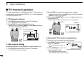
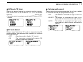
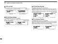
■ TV channel operation
TV channel operation is available only when TV channels are
programmed using the optional RS-91. (p. 121) Also available
for A band operation only.
w Rotate [DIAL] to select the channel to be skipped.
• To clear the skip setting, rotate [DIAL] while pushing and holding
[BAND] to select a skip channel.
e Push and hold [SKIP](5) for 1 sec. to toggle the skip setting ON and OFF.
D TV channel receiving
q Push [CALL] several times to select TV channels.
• “SKIP” appears when the channel is set as skip channel.
[DIAL]
• “TV” and channel number appear.
Appears
w Rotate [DIAL] to select the desired channel.
+DUP DTCS
WFM
PRIO WX EMR
• While pushing and holding [BAND], rotating [DIAL] selects the
all channels including skip channel.
[DIAL]
12 ch
A
MemoName P
TV mode indication
LOW
ATT
Channel indication
25
SKIP
µ
TV
+DUP DTCS
WFM
PRIO WX EMR
A
10 ch
MemoName
LOW
ATT
µ
25
P SKIP
TV
D Skip channel setting
Unwanted channels can be skipped for rapid selection, etc.
q Push [CALL] several times to select TV channels.
• “TV” and channel number appear.
D Automatic TV channel programming
TV channels can be programmed automatically.
q Push [CALL] several times to
select TV channels.
• “TV” and channel number appear.
w Push [SCAN](2) to start TV
channel programming.
+DUP DTCS
WFM
PRIO WX EMR
A
LOW
ATT
• The programming will automatically stop after scanning all channels.
28
2 ch
MemoName P
µ
25
SKIP
TV
REPEATER AND DUPLEX OPERATIONS
6
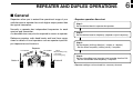
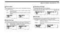
■ General
Repeaters allow you to extend the operational range of your
radio because a repeater has much higher output power than
the typical transceiver.
Normally, a repeater has independent frequencies for each
receiver and transmitter.
A subaudible tone may also be required to access a repeater.
Reference amateur radio hand books and local ham magazines for details of local repeaters such as repeater input/output frequencies and locations.
Repeater
144.700 MHz
145.300 MHz
Station A
144.700 MHz
145.300 MHz
Uplink
(transmitting freq.)
Downlink
(receiving freq.)
Station B
• Repeater operation flow chart
Step 1:
Set the desired band to operate the repeater.
Step 2:
Set the desired receive frequency (repeater output frequency).
Step 3:
Set the duplex (shifting) direction (– duplex or +duplex).
- Set the offset frequency (shifting value), if required.
Step 4:
Set the subaudible tone (repeater tone) encoder function ON.
- Set the subaudible tone frequency, if required.
• Repeater settings can be stored into a memory channel.
1
2
3
4
5
6
7
8
9
10
11
12
13
14
15
16
17
18
19
29
6
REPEATER AND DUPLEX OPERATIONS
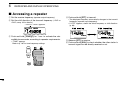
■ Accessing a repeater
q Set the receive frequency (repeater output frequency).
w Set the shift direction of the transmit frequency. (–DUP or
+DUP; see p. 32 for details.)
“–DUP”or “+DUP” appears.
r Push and hold [PTT] to transmit.
• The displayed frequency automatically changes to the transmit
frequency (repeater input frequency).
• If “OFF” appears, check the offset frequency or shift direction.
(p. 30)
While receiving
-DUP TONE
FM
A
145300
-DUP TONE
FM
A
145 300
P SKIP
e Push and hold [TONE](7) for 1 sec. to activate the subaudible tone encoder, according to repeater requirements.
• “TONE” appears.
Refer to p. 107 for tone frequency settings.
30
While transmitting
-DUP TONE
FM
A
144700
P SKIP
t Release [PTT] to receive.
y Push and hold [SQL] to check whether the other station’s
transmit signal can be directly received or not.
REPEATER AND DUPLEX OPERATIONS
6
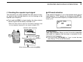
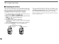
D Checking the repeater input signal
D Off band indication
The transceiver can check whether the other station’s transmit signal can be received directly or not, by listening on the
repeater input frequency.
If the transmit frequency is out of the amateur band, the off
band indication, “OFF,” appears on the display when [PTT] is
pushed. Check the offset frequency or duplex direction in this
case. (p. 32)
➥ Push and hold [SQL] to check whether the other station’s
transmit signal can be directly received or not.
• When the other station’s signal can be directly received, move
to a non-repeater frequency to use simplex. (duplex OFF)
-DUP TONE
FM
A
OFF
P SKIP
Indication while receiving.
-DUP TONE
FM
A
145300
P SKIP
Push and hold
Receives –0.6 MHz shift frequency.
-DUP TONE
FM
A
144 700
P SKIP
Blinks while pushing and holding [SQL].
✔ CONVENIENT!
Tone scan function: When you don’t know the subaudible
tone used for a repeater, the tone scan is convenient for detecting the tone frequency.
➥ Push and hold [T.SCAN](9) for 1 sec. to start the tone
scan. See p. 112 for more information.
1
2
3
4
5
6
7
8
9
10
11
12
13
14
15
16
17
18
19
31
6
REPEATER AND DUPLEX OPERATIONS
■ Duplex operation
Although [DIAL] and [ï](5) are used for description in this
∫](2)/[√
√](8) and [≈
≈](6) are available instead of
section, [∫
[DIAL] and [ï](5).
D Setting duplex direction
➥ Push and hold [DUP](4) for 1 sec. to select “–DUP” or
“+DUP”.
• “–DUP” or “+DUP” indicates the transmit frequency for minus
shift or plus shift, respectively.
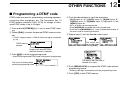
D Setting offset frequency
q Enter “OFFSET FREQ” in DUP/TONE… set mode. (p. 97)
MENU screen ➪ DUP/TONE… ➪ OFFSET FREQ
• When offset frequency is 0.6 MHz.
(Push [MENU/LOCK]) (Rotate [DIAL]†, then push [ï](5)†.)
w Rotate [DIAL]† to set offset frequency.
• 1 MHz and 10 MHz tuning steps are available by pushing and
holding [MHz](VFO) for 1 sec.: push [MHz](VFO) to cancel it.
Ω](4)) to return to DUP/TONE… set mode,
e Push [ï](5) (or [Ω
and push [MENU/LOCK] to return to frequency indication.
No offset frequency
OFFSET FREQ
0.000.00
5.0 MHz offset
OFFSET FREQ
5.000.00
†[DIAL]
32
∫](2)/[√
√](8)
↔ [∫
≈](6)
[ï](5) ↔ [≈
REPEATER AND DUPLEX OPERATIONS
6
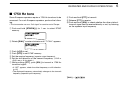
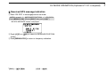
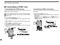
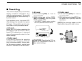
■ 1750 Hz tone
Some European repeaters require a 1750 Hz tone burst to be
accessed. For such European repeaters, perform the following.
• This tone can be use as a ‘Call signal’ in countries out of Europe.
q Push and hold [DTMF.M](.) for 1 sec. to select DTMF
memory.
i Push and hold [PTT] to transmit.
o Release [PTT] to receive.
!0 Push and hold [SQL] to check whether the other station’s
transmit signal can be received directly or not, by listening
on the repeater input frequency.
DTMF MEMORY
r
Ch01
w Rotate [DIAL]† counter-clockwise until “T-CALL” appears.
DTMF MEMORY
r
T-CALL
e Push [ï](5) to set.
r Push [VFO] to exit DTMF memory.
t Set the receive frequency (repeater output frequency).
y Set the shift direction of the transmit frequency. (–DUP or
+DUP; see p. 32 for details.)
u While pushing [PTT], push [SQL] to transmit a 1750 Hz
tone burst signal.
• If “OFF” appears, check the offset frequency or shift direction.
(p. 97)
• The displayed frequency automatically changes to the transmit
frequency (repeater input frequency).
†[DIAL]
∫](2)/[√
√](8)
↔ [∫
1
2
3
4
5
6
7
8
9
10
11
12
13
14
15
16
17
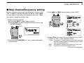
18
19
33
7
DV MODE OPERATION (Optional UT-121 is required)
Although [DIAL] and [ï](5) are used for description in this
∫](2)/[√
√](8) and [≈
≈](6) are available instead of
section, [∫
[DIAL] and [ï](5).
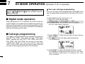
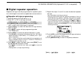
■ Digital mode operation
When the optional UT-121 is installed, the IC-E91 can be operated in digital voice mode and low-speed data operation for
both transmit and receive. It can also be connected to a GPS
receiver (compatible with an RS-232 output/NMEA format/4800 bps)
and transmit/receive position data.
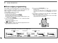
D Your own call sign programming
Your own call sign must be programmed for both digital voice
and low-speed data communications (including GPS transmission).
q Select B band as the main band. (p. 14)
w Enter “MY” in call sign set mode.
MENU screen ➪ CALL SIGN ➪ MY
(Push [MENU/LOCK]) (Rotate [DIAL]†, then push [ï](5)†.)
• MY CALL SIGN screen is displayed.
MY CALL SIGN
M01
r
/
:SET
:BACK
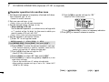
■ Call sign programming
Four types of call sign memories are available; your own call
sign “MY CALL SIGN,” other station call sign “YOUR CALL
SIGN,” repeater call sign “RPT1 CALL SIGN” and “RPT2
CALL SIGN.” “MY CALL SIGN” can store up to 6 call signs,
“YOUR CALL SIGN” can store up to 60 call signs and
“RPT1/2 CALL SIGN” can store up to 60 call signs, and each
call sign can be programmed with up to 8 characters.
:SEL
:EDIT
CLR:CLR
e Rotate [DIAL]† to select the desired call sign memory,
“M01” to “M06.”
≈](6) to enter call sign programming mode.
r Push [≈
• The 1st digit blinks.
MY CALL SIGN
M01
†
/
r
:SET
:SEL
AB
CLR:CLR
A/a:CHAR
:CUR
t Rotate
[DIAL]†
to select the desired character or code.
• Push [A/a](3) to change the character group from “AB” (alphabetical characters; capital letters), “12” (numbers) and “/” (symbols) in sequence.
34
DV MODE OPERATION (Optional UT-121 is required)
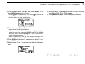
≈](6) to select 2nd digit, then rotate [DIAL]† to sey Push [≈
lect the desired character or code.
≈](6) to move the cursor right; push [Ω
Ω](4) to move the
• Push [≈
cursor left.
• 2nd digit blinks (1st digit stops blinking).
!0 Push [ï](5) to store the programmed call sign with note
and returns to MY CALL SIGN screen.
!1 Push [MENU/LOCK] to return to frequency indication.
MY CALL SIGN
M01
M†
/
AB
r
:SET
:SEL
CLR:CLR
A/a:CHAR
:CUR
u Repeat the steps t and y to enter your own call sign.
• Up to a 8-digit of call sign can be set.
≈](6) or [Ω
Ω](4) to
• If an un-necessary character is entered, push [≈
select the character, then push [CLR](1) to erase the selected
character, or push and hold [CLR](1) for 1 sec. to erase all characters following the cursor.
• When programming a note (Up to a 4-digit for operating radio
type or area, etc.), go to step i, otherwise go to step !0.
≈](6) several times to set the cursor beside “/” indii Push [≈
cation.
o Repeat steps t to y to program the desired 4-character
note.
MY CALL SIGN
M01
MYCALL
/IC91
r
:SET
:BACK
7
:SEL
:EDIT
CLR:CLR
†[DIAL]
∫](2)/[√
√](8)
↔ [∫
≈](6)
[ï](5) ↔ [≈
1
2
3
4
5
6
7
8
9
10
11
12
13
14
15
16
17
18
19
35
7
DV MODE OPERATION (Optional UT-121 is required)
D Station call sign programming
Station call sign must be programmed for the specified station call as well as repeater operation in both digital voice and
low-speed data communications.
q Select B band as the main band. (p. 14)
w Enter “UR” in call sign set mode.
MENU screen ➪ CALL SIGN ➪ UR
≈](6) to select 2nd digit, then rotate [DIAL]† to sey Push [≈
lect the desired character or code.
≈](6) to move the cursor right; push [Ω
Ω](4) to move the
• Push [≈
cursor left.
• 2nd digit blinks (1st digit stops blinking).
YOUR CALL SIGN
rU01
AB
S†
(Push [MENU/LOCK]) (Rotate [DIAL]†, then push [ï](5)†.)
• YOUR CALL SIGN screen is displayed.
:SET
:SEL
CLR:CLR
A/a:CHAR
:CUR
0:CQ
YOUR CALL SIGN
U
CQCQCQ
u Repeat the steps t and y to enter the desired station call
sign.
r
:SET
:BACK
:SEL
:EDIT
CLR:CLR
e Rotate [DIAL]† to select the desired call sign memory,
“U01” to “U60.”
≈](6) to enter call sign programming mode.
r Push [≈
• The 1st digit blinks.
YOUR CALL SIGN
U01
STATION1
r
YOUR CALL SIGN
rU01
AB
†
:SET
:BACK
:SEL
:EDIT
CLR:CLR
:SET
:SEL
CLR:CLR
A/a:CHAR
:CUR
0:CQ
t Rotate [DIAL]† to select the desired character or code.
• Push [A/a](3) to change the character group from “AB” (alphabetical characters; capital letters), “12” (numbers) and “/” (symbols) in sequence.
36
• Up to an 8-digit of call sign can be set.
≈](6) or [Ω
Ω](4) to
• If an un-necessary character is entered, push [≈
select the character, then push [CLR](1) to erase the selected
character, or push and hold [CLR](1) for 1 sec. to erase all characters following the cursor.
i Push [ï](5) to store the programmed call sign and returns
to YOUR CALL SIGN screen.
o Push [MENU/LOCK] to return to frequency indication.
DV MODE OPERATION (Optional UT-121 is required)
NOTE: During the call sign programming mode (r to u),
push [CQ](0) to set “CQCQCQ,” and push [CQ](0) again
to return to the previously stored call sign.
✔ For your information
The IC-E91 has call sign edit record function.
When editing a call sign stored in a call sign memory, regular
memory or call channel, the default setting is to store the
edited call sign into a blank channel automatically. (“FULL” is
displayed when all call sign memory is programmed.)
The edited call sign can be over-written when the setting of
the EDIT RECORD is set to OFF or SELECT. (p. 95)
However, you must manually over-write a programmed call
sign in regular memory and call channels. (Temporary operation without over-writing is possible.)
†[DIAL]
∫](2)/[√
√](8)
↔ [∫
≈](6)
[ï](5) ↔ [≈
7
1
2
3
4
5
6
7
8
9
10
11
12
13
14
15
16
17
18
19
37
7
DV MODE OPERATION (Optional UT-121 is required)
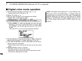
■ Digital voice mode operation
qSet the desired frequency in B band. (pgs. 14, 18)
• Select output power, if desired. (p. 24)
w Select DV mode. (p. 21)
e Set your own call sign for DV operation as follows.
z Enter “MY” in call sign set mode.
MENU screen ➪ CALL SIGN ➪ MY
(Push [MENU/LOCK]) (Rotate [DIAL]†, then push [ï](5)†.)
xRotate [DIAL]† to select the desired your own call sign
channel (if you have programmed several call signs) then
push [ï](5) to set the call sign and return to CALL SIGN
screen.
• See page 34 for your own call sign programming details.
CALL SIGN
UR:
R1:
R2:NOT USE*
MY:MYCALL
/IC91
r
rSet the desired call sign as described in “When calling the
desired station (p. 39)” or “When sending a CQ (p. 39).”
tPush and hold [PTT] to transmit and speak into the microphone at normal voice level.
• Tx/Rx indicator lights red and the RF meter shows the output
power.
y Release [PTT] to return to receive.
• The other station call sign will be received.
• Received call signs can be stored into the received call record
automatically. See page 93 for details.
38
NOTE: The digital mode operation is vastly different from
FM mode. One of the differences is in digital mode the
squelch does not function as in FM mode. Changing the
squelch setting will not open it to hear the hiss of “White
Noise.” It only activates for digital squelch functions such
as CSQL (Digital code squelch) or DSQL (Digital call sign
squelch).
DV MODE OPERATION (Optional UT-121 is required)
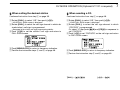
D When calling the desired station
D When sending a CQ
Continued instruction from step x on page 38.
Continued instruction from step x on page 38.
cRotate [DIAL]† to select “UR,” then push [ï](5)†.
cRotate [DIAL]† to select “UR,” then push [ï](5)†.
• YOUR CALL SIGN screen is displayed.
vRotate [DIAL]† to select the call sign channel in which desired station’s call sign is programmed.
• See page 36 for station call sign programming details.
bPush [ï](5) to set the station’s call sign and return to
CALL SIGN screen.
CALL SIGN
• YOUR CALL SIGN screen is displayed.
vRotate [DIAL]† to select the call sign channel in which
“CQCQCQ” is programmed.
≈](6) and [CQ](0) in sequence to
Or, select “U” then push [≈
set “CQCQCQ.”
bPush [ï](5) to set “CQCQCQ” as the call sign and return
to CALL SIGN screen.
UR:STATION1
R1:
R2:NOT USE*
MY:MYCALL
/IC91
r
nPush [MENU/LOCK] to return to frequency indication.
m Perform the instruction steps t and y on page 38.
7
CALL SIGN
UR:CQCQCQ
R1:
R2:NOT USE*
MY:MYCALL
/IC91
r
nPush [MENU/LOCK] to return to frequency indication.
m Perform the instruction step t and y on page 38.
†[DIAL]
∫](2)/[√
√](8)
↔ [∫
≈](6)
[ï](5) ↔ [≈
1
2
3
4
5
6
7
8
9
10
11
12
13
14
15
16
17
18
19
39
7
DV MODE OPERATION (Optional UT-121 is required)
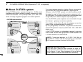
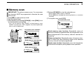
■ About D-STAR system
In the D-STAR system, repeater linking via a 10 GHz band
backbone and internet network (gateway connection) capabilities are available. This system provides you to with much
wider coverage range during digital voice mode operation.
Also, the D-STAR system repeaters are connectable through
the internet— gateway connection capability.
• D-STAR system outline
Repeater A
For current repeater operation, stations that are communicating must both be in the same repeater’s operating area.
However, in the D-STAR system as in the illustration at left,
the repeaters can be linked via the system repeaters (with a
10 GHz signal). Thus stations A and B can communicate even
though they are in different repeater operating areas.
10 GHz
Repeater B
144/430 MHz
144/430 MHz
Station
B
Station
A
Internet
network
10 GHz
For example, when station B uses the gateway connection
station B can communicate with the station C!
By using the gateway connection, long distance communication like DX operation may be possible with 144 or 430 MHz
digital voice!
In the D-STAR system, an independent repeater’s operating
area is called an Area and a group that of linked repeaters via
a 10 GHz backbone is called a Zone.
NOTE: The digital repeater for IC-E91 (144 MHz or
430 MHz of amateur radio band operation) is not available
in European countries at present of May 2006.
Repeater D
Repeater C
144/430 MHz
Station C
40
144/430 MHz
Station D
About time-out timer function
The IC-E91 has a time-out timer function for digital repeater operation. The timer limits a continuous transmission for approx. 10 min. Warning beeps will sound before
30 sec. (approx.) and just before the timer functioning.
DV MODE OPERATION (Optional UT-121 is required)
7
■ Digital repeater operation
Repeater call signs must be programmed for repeater operation in both digital voice and low-speed data communications.
D Repeater call sign programming
q Select B band as the main band. (p. 14)
w Enter “R1” or “R2” in call sign set mode.
MENU screen ➪ CALL SIGN ➪ R1/R2
(Push [MENU/LOCK]) (Rotate [DIAL]†, then push [ï](5)†.)
• RPT1 or RPT2 CALL SIGN screen is displayed.
u Repeat the steps t and y to enter the desired repeater
call sign.
• Up to an 8-digit of call sign can be set.
• Push [7] when setting with the gateway connection if the selected repeater has gateway capability. (The gateway connection can be set in RPT1 only when “NOT USE✱” is set to RPT2.)
≈](6) or [Ω
Ω](4) to
• If an un-necessary character is entered, push [≈
select the character, then push [CLR](1) to erase the selected
character, or push and hold [CLR](1) for 1 sec. to all characters
following the cursor.
RPT1 CALL SIGN
e Rotate [DIAL]† to select the desired call sign memory,
“R01” to “R60.”
≈](6) to enter call sign programming mode.
r Push [≈
R01
RPT1AA G
r
:SET
:BACK
• The 1st digit blinks.
t Rotate [DIAL]† to select the desired character or code.
• Push [A/a](3) to change the character group from “AB” (alphabetical characters; capital letters), “12” (numbers) and “/” (symbols) in sequence.
• Set “/” at the 1st digit then set the desired area repeater’s call
sign (in a different zone) for CQ call (“/” stands for “CQCQCQ”) in
a different zone operation. (p. 44)
:SEL
:EDIT
CLR:CLR
i Push [ï](5) to store the programmed call sign and returns
to RPT1 or RPT2 CALL SIGN screen.
o Push [MENU/LOCK] to return to frequency indication.
≈](6) to select 2nd digit, then rotate [DIAL]† to sey Push [≈
lect the desired character or code.
≈](6) to move the cursor right; push [Ω
Ω](4) to move the
• Push [≈
cursor left.
• 2nd digit blinks (1st digit stops blinking).
†[DIAL]
∫](2)/[√
√](8)
↔ [∫
≈](6)
[ï](5) ↔ [≈
1
2
3
4
5
6
7
8
9
10
11
12
13
14
15
16
17
18
19
41
7
DV MODE OPERATION (Optional UT-121 is required)
D Repeater operation in the same zone
qSet the desired repeater’s frequency, offset and shift direction in B band. (pgs. 18, 32)
t Push [PTT] to transmit; release to receive.
• Select DV mode in advance. (p. 21)
w Set your own call sign. (p. 38)
• See p. 34 for your own call sign programming.
e Set the desired station call sign. (p. 39)
• See p. 36 for station call sign programming.
r Set the repeater’s call sign as follows;
z Enter “R1” in call sign set mode.
MENU screen ➪ CALL SIGN ➪ R1
(Push [MENU/LOCK]) (Rotate [DIAL]†, then push [ï](5)†.)
xRotate [DIAL]† to select the nearest repeater’s call sign.
cPush [ï](5) to set the call sign for “R1.”
• Return to CALL SIGN screen.
vRotate [DIAL]† to select “R2” then push [ï](5)†.
• RPT2 CALL SIGN screen is displayed.
bRotate [DIAL]† to select the desired repeater’s (in the
same zone) call sign.
• Select “NOT USE✱” when not operating RPT2.
nPush [ï](5) to set the call sign for “R2.”
• Return to CALL SIGN screen.
CALL SIGN
UR:CQCQCQ
R1:RPT1AA
R2:NOT USE*
MY:MYCALL
/IC91
r
mPush [MENU/LOCK] to return to frequency indication.
42
†[DIAL]
∫](2)/[√
√](8)
↔ [∫
≈](6)
[ï](5) ↔ [≈
DV MODE OPERATION (Optional UT-121 is required)
7
• Setting example 1
Zone
Area 1
Repeater 1
: A11111
Area 2
Repeater 2
: A22222
Station A
: A2222A
Station B
: A2222B
✔ What is the area?
The Area is the communication range that is
covered by a local repeater.
A Local repeater is called an area repeater in
the D-STAR system.
❑ The setting when Station A is calling Station B
UR
: A2222B
R1
: A22222
R2
: NOT USEQ
MY
: A2222A
Area 3
(Gateway)
Internet
network
to another Zone
Repeater 3
: A33333
Area 4
Repeater 4
: A44444
Station C
: A4444C
✔ What is the zone?
The Zone is composed of several areas, that
are linked by the 10 GHz microwave signal.
The areas 1 to 4 make up a zone in the example above.
❑ The setting when Station A is making a CQ call in area 1
UR
: CQCQCQ
R1
: A22222
R2
: A11111
MY
: A2222A
❑ The setting when Station A is calling Station C
UR
: A4444C
R1
: A22222
R2
: A44444
MY
: A2222A
1
2
3
4
5
6
7
8
9
10
11
12
13
14
15
16
17
18
19
43
7
DV MODE OPERATION (Optional UT-121 is required)
D Repeater operation into another zone
qSet the desired repeater’s frequency, offset and shift direction in B band. (pgs. 18, 32)
nPush [ï](5) to set the call sign for “R2.”
• Return to CALL SIGN screen.
• Select DV mode in advance.
w Set your own call sign. (p. 38)
• See p. 34 for your own call sign programming.
e Set the desired station call sign. (p. 39)
• When making a CQ call
Set the desired repeater’s (in a different zone) call sign with
a “/” symbol at the 1st digit, for the area in which you
want to make a CQ call, into “UR.”
CALL SIGN
UR:CQCQCQ
R1:RPT1AA
R2:NOT USE*
MY:MYCALL
/IC91
r
mPush [MENU/LOCK] to return to frequency indication.
t Push [PTT] to transmit; release to receive.
• See p. 36 for station call sign programming.
r Set the repeater’s call sign as follows;
z Enter “R1” in call sign set mode.
MENU screen ➪ CALL SIGN ➪ R1
(Push [MENU/LOCK]) (Rotate [DIAL]†, then push [ï](5)†.)
xRotate [DIAL]† to select the nearest repeater’s call sign.
• If the nearest repeater is gateway repeater, select the repeater’s call sign with “G” setting at the 8th digit.
cPush [ï](5) to set the call sign for “R1.”
• Return to CALL SIGN screen.
vRotate [DIAL]† to select “R2” then push [ï](5)†.
bRotate [DIAL]† to select the gateway repeater’s (in the
same zone) call sign.
• The call sign should have “G” setting at the 8th digit.
• When gateway repeater call sign is set in “R1,” select “NOT
USE✱” for “R2” setting.
†[DIAL]
44
∫](2)/[√
√](8)
↔ [∫
≈](6)
[ï](5) ↔ [≈
DV MODE OPERATION (Optional UT-121 is required)
7
• Setting example 2
Zone A
Area 1
Area 2
Repeater 1
: A11111
Repeater 2
: A22222
Station A
: A2222A
Area 3
(Gateway)
Repeater 3
: A33333
Area 4
Repeater 4
: A44444
Internet
network
Station B
: A3333B
Zone B
Area 5
Repeater 5
: B55555
Area 6
Repeater 6
: B66666
Area 7
(Gateway)
Area 8
Repeater 7
: B77777
Repeater 8
: B88888
Station C
: B6666C
❑ The setting when Station A is calling Station C
UR
: B6666C
R1
: A22222
R2
: A33333 G
MY
: A2222A
❑ The setting when Station A is making a CQ call in area 8
UR
: /B88888
R1
: A22222
R2
: A33333 G
MY
: A2222A
❑ The setting when Station B is calling Station C
UR
: B6666C
R1
: A33333 G
R2
: NOT USE✱
MY
: A3333B
1
2
3
4
5
6
7
8
9
10
11
12
13
14
15
16
17
18
19
45
7
DV MODE OPERATION (Optional UT-121 is required)
■ Received call sign
When a call is received in DV mode, the calling station and
the repeater call signs being used can be stored into the received call record. The stored call signs are viewable in the
following manner.
Up to 20 calls can be recorded.
• Station call sign
• Called station call sign
RX CALL SIGN
RX01
CALLER:
AAAAAA
/
RX CALL SIGN
RX01
CALLED:
CQCQCQ
r
:CALLED
:COPY
r
:RXRPT1
:SEL
CLR:CLR
:COPY
:SEL
CLR:CLR
Push
D Desired call record indication
q Enter RX call sign set mode.
MENU screen ➪ RX CALL SIGN
RX CALL SIGN
RX CALL SIGN
RX01
RXRPT2:
RX01
RXRPT1:
r
r
(Push [MENU/LOCK]) (Rotate [DIAL]†, then push [ï](5)†.)
:CALLER
• RX CALL SIGN screen is displayed.
:COPY
wRotate
to select the desired record channel.
eTo confirm the received call, push [ï](5) several times to
select the desired call sign from CALLER, CALLED,
RXRPT1 and RXRPT2.
[DIAL]†
CALLER
CALLED
RXRPT1
RXRPT2
: The station call sign that made a call.
: The station call sign called by the caller.
: The repeater call sign used by the caller station.
: The repeater call sign linked from RXRPT1.
r Push [MENU/LOCK] to return to frequency indication.
:SEL
CLR:CLR
• Repeater 2 call sign
:RXRPT2
:COPY
:SEL
CLR:CLR
• Repeater 1 call sign
NOTE: When a call is received in DV mode when the
power save function is activated, the call sign may not be
received correctly.
This is normal, not a malfunction, because of header of the
call sign cannot be detected during power save.
Turn the power save function OFF (p. 114) if you want to
receive a call sign correctly even in stand-by condition.
✔ For your information
When receiving a call, the received station call sign is automatically displayed and scrolled in sequence at the bottom
line of the function display.
This can be turned OFF in display set mode. (p.100)
†[DIAL]
46
∫](2)/[√
√](8)
↔ [∫
≈](6)
[ï](5) ↔ [≈
DV MODE OPERATION (Optional UT-121 is required)
7
D One-touch reply using the call record
The stored call signs in the call record can be used to the call.
qAfter receiving a call, push and hold [RX➝CS](CALL) for
1 sec.
Or, while pushing and holding [RX➝CS](CALL), rotate
[DIAL] to select the desired call sign record.
Important!
Setting call signs with the “One-touch reply using the call
record” operation as at left are for temporary operation only.
Therefore, the set call signs will be overwritten when another call record is used to set call signs.
• Never saved into a call sign memory.
-DUP
DV
B
439 706 25
If you want to save the set call signs, see “Copying the call
record contents into call sign memory” (p. 50) for details.
AAAAAA
The received call sign is displayed while pushing and
holding [CALL/RX➝CS] when [DIAL] is rotated while
[CALL/RX➝CS] is pushed.
✔ For your information
When a call specifying your call sign is received, the call signs
of the calling station and the repeater it is using can be used
for operation automatically.
• Set your own call sign (MY) in advance. (p. 34)
• The call sign stored in “CALLER” is stored as “UR,” “RXRPT1” is
stored as “R2” and “RXRPT2” is stored as “R1.”
• Error beeps sound when a call sign is received incorrectly, and
no call sign is set in this case.
• When “RX call sign auto write” (p. 93) is set to “AUTO,” the
station call sign in “CALLER” is set to “UR” automatically.
wPush [PTT] to transmit; release to receive.
• When “Repeater call sign auto write” (p. 93) is set to “AUTO,”
the stored station call sign in “RXRPT1” is stored as “R2”
and “RXRPT2” is stored as “R1” automatically.
1
2
3
4
5
6
7
8
9
10
11
12
13
14
15
16
17
18
19
47
7
DV MODE OPERATION (Optional UT-121 is required)
■ Copying the call sign
D Copying the call sign memory contents
This function is convenient when or modifying a part of the
current call sign.
NOTE: Make sure that the “EDIT RECORD” item in DV set
mode is set to “AUTO” or “SELECT” in advance. (p. 95)
qDuring DV mode operation, enter call sign set mode.
MENU screen ➪ CALL SIGN
(Push [MENU/LOCK]) (Rotate [DIAL]†, then push [ï](5)†.)
• CALL SIGN screen is displayed.
wRotate [DIAL]† to select “UR,” “R1” or “R2” as desired, then
push [ï](5)†.
eRotate [DIAL]† to select the desired call sign channel to be
copied.
• U01–U60 and R01–R60 are available.
48
• When “AUTO” is set to “EDIT RECORD” item
≈](6) to select the call sign programming mode.
r Push [≈
• A blank channel is selected automatically.
• The 1st digit of the selected call sign blinks.
YOUR CALL SIGN
rU21
AB
†AAAAA
AAAAA
:SET
:SEL
CLR:CLR
A/a:CHAR
:CUR
0:CQ
A blank channel
number blinks.
tEdit or modify the selected call sign as described in “D Station call sign programming” (p. 36) or “D Repeater call sign
programming” (p. 41).
yPush [ï](5) to store the edited/modified call sign into the
selected blank channel.
NOTE: The message “FULL” is displayed when no blank
channel is available in station or repeater call sign memory.
Select the desired call sign channel number as described
in step u of “• When “SELECT” is set to “EDIT RECORD”
item” at right-hand page in this case.
DV MODE OPERATION (Optional UT-121 is required)
• When “SELECT” is set to “EDIT RECORD” item
≈](6) to select the call sign programming mode.
r Push [≈
• The 1st digit of the selected call sign blinks.
tEdit or modify the selected call sign as described in “D Station call sign programming” (p. 36) or “D Repeater call sign
programming” (p. 41).
yPush [ï](5).
• Call sign channel number blinks.
YOUR CALL SIGN
rU21
AB
AAAAA1
:SET
:SEL
CLR:CLR
A/a:CHAR
:CUR
0:CQ
Call sign channel
number bliks.
uRotate
to select the desired call sign channel to
store.
iPush [ï](5) to store the edited/modified call sign into the
selected channel.
[DIAL]†
†[DIAL]
∫](2)/[√
√](8)
↔ [∫
≈](6)
[ï](5) ↔ [≈
7
1
2
3
4
5
6
7
8
9
10
11
12
13
14
15
16
17
18
19
49
7
DV MODE OPERATION (Optional UT-121 is required)
D Copying the call record contents into call sign memory
This is a way to copying the call record contents (“CALLER,”
“RXRPT1” and “RXRPT2”) into call sign memory (“UR,” “R1” and
“R2”) at the same time or individually.
qPerform the steps q to e of “D Desired call record indication” (p. 46) to select the desired call record or call sign.
≈](6) to select copy select mode.
w Push [≈
• COPY SELECT screen is displayed.
• When “CALLER,” “RXRPT1” or “RXRPT2” is
selected
≈](6) then rotate [DIAL]† to select the desired conzPush [≈
dition of call sign memory channel selection to be copied to
from “AUTO” and “LIST SEL.”
• “AUTO” selection won’t appear when the appropriate call sign
memory has no blank channel.
• Go to step r when “AUTO” is selected.
COPY SELECT
COPY SELECT
RX01
RX01
rALL
rAUTO
LIST SEL
:BACK
:SEL
:LIST
C:CURR
eRotate [DIAL]† to select the desired call sign to be copied
from “ALL,” “RXRPT1” and “RXRPT2.”
• “ALL” selection won’t appear when either station or repeater call
sign memory has no blank channel.
• When “ALL” is selected
≈](6) to copy the selected record’s contents into
➥ Push [≈
the appropriate call sign memory.
:BACK
:SEL
:LIST
≈](6), then select the desired call sign memory
xPush [≈
channel to copy to with [DIAL].
≈](6) to copy the call sign into the selected call
cPush [≈
sign memory.
• Returns to RX CALL SIGN screen automatically.
r Push [MENU/LOCK] to return to frequency indication.
• Returns to RX CALL SIGN screen automatically.
†[DIAL]
50
∫](2)/[√
√](8)
↔ [∫
≈](6)
[ï](5) ↔ [≈
DV MODE OPERATION (Optional UT-121 is required)
■ Break-in communication
The break-in function allows you to break into a conversation,
where the two original stations are communicating with call
sign squelch enabled.
qWhile receiving an another station’s communication, push
and hold [RX➝CS](CALL) for 1 sec. to set the communicating station’s call sign.
• When a call sign has not been received correctly, error beeps
sound and no call sign is set. Receive the call sign of a communicating signal again, or set the call sign manually.
wPush and hold [BK](9) for 1 sec. to turn the break-in function ON.
• “BK” appears.
DV
B
BK
430 712 50
Appears
7
• How to use the break-in?
While operating with the call sign squelch (p. 110), the
squelch never opens (no audio sounds) even if a call is received, unless your own call sign (“MY”) is specified.
However, when the call including the “BK ON” signal (breakin call) is received, the squelch will open and audio sounds
even if the call is specified for another station.
• Station C calling to Station A with “BK OFF”
Station A and B are
communicating using the call sign
squelch.
Station A
Station B
Station B never hears that
Station C is calling Station A.
Station C
LOW
ATT
• Station C calling to Station A with “BK ON”
eWhen both stations are in standby, push [PTT] to transmit
a break-in call.
• The programmed call sign station receives the break-in call as
well as your call sign.
rWait for the reply call from the station who receives the
break-in call.
t After receiving the reply call, communicate normally.
yTo cancel the break-in, push and hold [BK](9) for 1 sec. to
turn OFF.
Station A and B are
communicating using the call sign
squelch.
Station A
Station B
Station B also hears that Station C is calling Station A.
Station C
1
2
3
4
5
6
7
8
9
10
11
12
13
14
15
16
17
18
19
51
7
DV MODE OPERATION (Optional UT-121 is required)
■ Message operation
D TX message programming
TX messages are available for up to 5 channels and each
channel can be programmed with a message of up to 20
characters. Available characters are 0 to 9, A to Z (capital letters), a to z (lower case letters), some symbols and space.
q Enter “TX MESSAGE” in message/position set mode.
MENU screen ➪ MESSAGE/POSITION ➪ TX MESSAGE
(Push [MENU/LOCK]) (Rotate [DIAL]†, then push [ï](5)†.)
• TX MESSAGE screen is displayed.
wRotate [DIAL]† to select the desired transmit message
channel.
• Ch01 to Ch05 and OFF are available.
• Previously message is displayed if programmed.
≈](6) to select the message edit condition.
e Push [≈
• The 1st digit of the message blinks.
• Push [A/a](3) to change the character group from “AB” (alphabetical characters; capital letters), “ab” (alphabetical characters;
lower case letters), “12” (numbers) and “ !” ” (symbols) in sequence.
≈](6) or [Ω
Ω](4) to
• If an un-necessary character is entered, push [≈
select the character, then push [CLR](1) to erase the selected
character, or push and hold [CLR](1) for 1 sec. to erase all characters following the cursor.
≈](6) to select 2nd digit, then rotate [DIAL]† to select
tPush [≈
the desired character or code.
≈](6) to move the cursor right; push [Ω
Ω](4) to move the
• Push [≈
cursor left.
• 2nd digit blinks (1st digit stops blinking).
y Repeat the steps r and t to enter the desired message.
• Up to 20-character messages can be set.
TX MESSAGE
TX MESSAGE
rCh01
rCh01
!'
'
Hello!†
Hello!
†
:SET
:BACK
r Rotate [DIAL]† to select the desired character or symbol.
:SEL
:EDIT
CLR:CLR
:SET
:SEL
CLR:CLR
A/a:CHAR
:CUR
u Push [ï](5) to store the message.
i Push [MENU/LOCK] to return to frequency indication.
52
DV MODE OPERATION (Optional UT-121 is required)
7
D Message Transmission
Select the message transmission function ON (Ch01–05) and
OFF. When a message channel is selected, the transceiver
transmits a text message (pre-programmed).
(default: OFF)
qSet the operating frequency, call signs and other settings,
such as repeater, as desired in B band.
wPerform the steps q to e in “D TX message programming” as at left.
eRotate [DIAL]† to select the desired message channel.
• “Ch01” to “Ch05” available.
• See left-hand pages for message programming.
rPush [ï](5) to set the message for transmission.
tPush [PTT] to transmit the selected message.
✔ For your information
The automatic received call sign and/or message indication
can be turned OFF in display set mode, if desired.
➥ RX CALL SIGN (p. 100)
➥ RX MESSAGE (p. 101)
NOTE: Only 1 message can be stored in the IC-E91. The
received message is cleared by turning power OFF, or
overwritten when another message is received.
A transmitted message that includes lower case characters from the IC-E91 may not be decoded and displayed
correctly by the ID-800H, IC-V82/U82, etc.
• The message is transmitted each time [PTT] is pushed.
• The message is transmitted each 30 sec. automatically during
continuous transmission.
y Release [PTT] to return to receive.
uWhen the reply call with a message is received, the call
sign and the message scrolls at the bottom of the function
display.
DV
B
430 712 50
MSG:Hello!
Scrolls the received message.
†[DIAL]
∫](2)/[√
√](8)
↔ [∫
≈](6)
[ï](5) ↔ [≈
1
2
3
4
5
6
7
8
9
10
11
12
13
14
15
16
17
18
19
53
7
DV MODE OPERATION (Optional UT-121 is required)
■ Automatic reply function
D RX message indication
The received message can also be checked in DV set mode.
q Select “RX MESSAGE” in message/position set mode.
MENU screen ➪ MESSAGE/POSITION ➪ RX MESSAGE
(Push [MENU/LOCK]) (Rotate [DIAL]†, then push [ï](5)†.)
The automatic reply function replies to calls by a station that
specified your call sign.
Two methods of replying are available— one is making a
reply call with your own call sign, and other one is making a
reply call with reply voice audio that has been recorded in DV
voice memory.
• The received message is displayed in RX MESSAGE screen.
RX MESSAGE
rMESSAGE:
Hello!
:BACK
:CALLER
√](8) to display the station call
wRotate [DIAL] or push [√
sign.
RX MESSAGE
rCALLER:
D Automatic reply function setting
q Enter “AUTO REPLY” in DV set mode. (p. 92)
MENU screen ➪ DV SET MODE ➪ AUTO REPLY
(Push [MENU/LOCK]) (Rotate [DIAL]†, then push [ï](5)†.)
• AUTO REPLY screen is displayed.
w Rotate [DIAL]† to select the desired reply condition.
OFF
: Deactivate the automatic reply function. (default)
ON
: Reply to the call with your own call sign.
VOICE : Reply to the call with the recorded voice memory.
BBBBBB
/
:BACK
AUTO REPLY
rOFF
:MSG
Ω](4) to return to MESSAGE/POSITION
ePush [ï](5) or [Ω
screen.
r Push [MENU/LOCK] to return to frequency indication.
ON
VOICE
e Push [ï](5).
• Returns to DV SET MODE screen automatically.
r Push [MENU/LOCK] to return to frequency indication.
54
DV MODE OPERATION (Optional UT-121 is required)
D Voice memory recording for automatic reply
IMPORTANT!
Deactivate the dualwatch function and set minimum [VOL]
level when recording the DV voice memo.
Otherwise received audio or unwanted noise from A band is
also recorded into the voice memory.
qSelect DV mode in B band, and deactivate the priority
watch (p. 83) if activated.
w Enter “REPLY VOICE” in DV voice memo set mode.
MENU screen ➪ DV VOICE MEMO ➪ REPLY VOICE
D Play-back or erase the voice memory
q Push [MENU/LOCK] to select menu mode indication.
wRotate [DIAL]† to select “DV VOICE MEMO,” then push
[ï](5)†.
eRotate [DIAL]† to select “REPLY VOICE,” then push
[ï](5)†.
• REPLY VOICE screen is displayed.
rTo play-back the recorded voice memory, push [ï](5).
≈](6) to cancel the play-back.
• Push [ï](5) again to pause, push [≈
tTo erase the recorded voice memory, push and hold
[CLR](1) for 1 sec.
(Push [MENU/LOCK]) (Rotate [DIAL]†, then push [ï](5)†.)
• REPLY VOICE screen is displayed.
REPLY VOICE
rREPLY
V
:
PTT: ●
:BACK
CLR:CLR
7
eWhile pushing and holding [PTT], speak into the microphone.
• Up to 10 seconds of message is recordable.
• The recording stops after 10 second or when [PTT] is released.
Ω](4) to return to DV VOICE MEMO screen.
r Push [Ω
t Push [MENU/LOCK] to return to frequency indication.
†[DIAL]
∫](2)/[√
√](8)
↔ [∫
≈](6)
[ï](5) ↔ [≈
1
2
3
4
5
6
7
8
9
10
11
12
13
14
15
16
17
18
19
55
7
DV MODE OPERATION (Optional UT-121 is required)
■ EMR communication
■ Low-speed data communication
The EMR communication mode is available for digital mode
operation. In the EMR communication mode, no call sign setting is necessary. When an EMR communication mode signal is received, the audio (voice) will be heard at the specified
level even the volume setting level is set to minimum level, or
digital call sign/digital code squelch is in use.
In addition to the digital voice communication, low-speed data
communication is available.
The optional OPC-1529R DATA COMMUNICATION CABLE and serial data communication software (purchase locally) are required in addition.
qSet the desired frequency in 144 or 430 MHz band then
push and hold [EMR](.) until 3 short and 1 long beeps
sound to turn the EMR setting ON.
DV
pability.
NOTE: Turn OFF the GPS mode (p. 58) in advance to operate the low-speed data communication.
• “EMR” appears
B
The optional RS-91 REMOTE CONTROL SOFTWARE (OPC-1529R
supplied) also includes a low-speed data communication ca-
EMR
430 712 50
Appears
D Connection
Connect the transceiver to your PC using with the optional
OPC-1529R as illustrated below.
w Operate the transceiver normal way.
eTo cancel the EMR communication mode, push and hold
[EMR](.) for 1 sec. to turn OFF.
to [DATA]
to
RS-232C
OPC-1529R
(optional)
56
DV MODE OPERATION (Optional UT-121 is required)
D Low-speed data communication application
setting
Configure the low-speed data communication application as
follows.
• Port
: The same COM port number as IC-E91’s
• Baud rate : 38.4 kbps (fixed value)
• Data
: 8 bit
• Parity
: None
• Stop
: 1 bit
• Flow control : Xon/Xoff
7
D Transmission condition setting
q Enter “DV DATA TX” in DV set mode. (p. 92)
MENU screen ➪ DV SET MODE ➪ DV DATA TX
(Push [MENU/LOCK]) (Rotate [DIAL]†, then push [ï](5)†.)
w Rotate [DIAL]† to select “PTT” or “AUTO.”
Ω](4)) to return to DV set mode, and push
ePush [ï](5) (or [Ω
[MENU/LOCK] to return to frequency indication.
D Low-speed data communication operation
NOTE: Confirm that in AUTO, the computer controls when
[PTT] is activated to send data and the user doesn’t have
to operate the radio.
qSet your own, station call signs, etc. as described in
“■ Digital voice mode operation” (p. 38) and “■ Digital repeater operation” (p. 41).
wRefer to the instructions of the low-speed data communication application.
e To transmit data
• With your voice audio, push and hold [PTT] to transmit while
sending data from the PC. Release [PTT] to receive.
• Under computer control, see Transmission condition setting at
right.
†[DIAL]
∫](2)/[√
√](8)
↔ [∫
≈](6)
[ï](5) ↔ [≈
1
2
3
4
5
6
7
8
9
10
11
12
13
14
15
16
17
18
19
57
7
DV MODE OPERATION (Optional UT-121 is required)
■ GPS operation
During GPS mode operation, a GPS receiver (RS-232C output/NMEA format) can be connected to the [DATA] socket of
the IC-E91 to indicate the current position (Latitude and Longitude). The position data is transmitted with your voice signals
at the same time.
D Sentence formatter setting
q Enter “GPS MODE” in DV set mode. (p. 94)
MENU screen ➪ DV SET MODE ➪ GPS MODE
(Push [MENU/LOCK]) (Rotate [DIAL]†, then push [ï](5)†.)
• GPS MODE screen is displayed.
In addition, the GPS message transmission is also available
for the GPS mode operation.
GPS MODE
OFF
rON
:SENTENCE
to [DATA]
to RS-232C port
(null modem
adapter is required)
OPC-1529R
(optional)
GPS
receiver
w Rotate [DIAL]† to select “ON.”
e Push [ï](5)† to select GPS SENTENCE screen.
rRotate [DIAL]† to select the desired GPS sentence, then
push [ï](5).
• A total 5 sentences, RMC, GGA, GLL, GSA and VTG are available.
t Rotate [DIAL]† to turn the sentence usage ON and OFF.
Ω](4)) to return to GPS SENTENCE
yPush [ï](5) (or [Ω
screen.
uRepeat the steps r to y to set another GPS sentence
usage.
• Up to 3 GPS sentences are usable at the same time.
i Push [MENU/LOCK] to return to frequency indication.
58
DV MODE OPERATION (Optional UT-121 is required)
7
D GPS message programming
q Enter “GPS” in message/position set mode.
MENU screen ➪ MESSAGE/POSITION ➪ GPS
(Push [MENU/LOCK]) (Rotate
[DIAL]†,
then push
t Repeat the steps r and t to enter the desired message.
• Up to 20-character messages can be set.
[ï](5)†.)
GPS MESSAGE
rDATA:
AB
Hello!†
Hello!
• GPS MESSAGE screen is displayed.
≈](6) to select the message edit condition.
w Push [≈
:SET
:SEL
:CUR
• The 1st digit of the message blinks.
CLR:CLR
A/a:CHAR
GPS MESSAGE
rDATA:
AB
†
:SET
:SEL
:CUR
y Push [ï](5) to store the message.
u Push [MENU/LOCK] to return to frequency indication.
CLR:CLR
A/a:CHAR
e Rotate [DIAL]† to select the desired character or symbol.
• Push [A/a](3) to change the character group from “AB” (alphabetical characters; capital letters), “ab” (alphabetical characters;
lower case letters), “12” (numbers) and “ !” ” (symbols) in sequence.
≈](6) to select 2nd digit, then rotate [DIAL]† to select
rPush [≈
the desired character or code.
≈](6) to move the cursor right; push [Ω
Ω](4) to move the
• Push [≈
cursor left.
• 2nd digit blinks (1st digit stops blinking).
†[DIAL]
∫](2)/[√
√](8)
↔ [∫
≈](6)
[ï](5) ↔ [≈
1
2
3
4
5
6
7
8
9
10
11
12
13
14
15
16
17
18
19
59
7
DV MODE OPERATION (Optional UT-121 is required)
D GPS message automatic transmission
D Position indication
q Enter “GPS AUTO TX” in DV set mode. (p. 95)
MENU screen ➪ DV SET MODE ➪ GPS AUTO TX
q Enter “POSITION” in message/position set mode.
MENU screen ➪ MESSAGE/POSITION ➪ POSITION
(Push [MENU/LOCK]) (Rotate [DIAL]†, then push [ï](5)†.)
• GPS AUTO RX screen is displayed.
(Push [MENU/LOCK]) (Rotate [DIAL]†, then push [ï](5)†.)
• GPS POSITION screen is displayed.
GPS POSITION
GPS AUTO TX
rMY
rOFF
5SEC
10SEC
30SEC
1MIN
wRotate [DIAL]† to select the desired position data transmitting interval from 5 sec., 10 sec., 30 sec., 1 min., 3 min.,
5 min., 10 min., 30 min. and OFF.
• The position data is transmitted only when [PTT] is pushed with
OFF setting, the data is transmitted automatically once every
5 sec., 10 sec., 30 sec., 1 min., 3 min., 5 min., 10 min. and
30 min. when the appropriate setting is selected.
• The GPS message is also transmitted if programmed.
Ω](4)) to return to DV SET MODE screen.
ePush [ï](5) (or [Ω
r Push [MENU/LOCK] to return to frequency indication.
NOTE: Your own call sign (“MY”) should be set to activate
the GPS automatic transmission.
60
POSITION
34.56.789 N
123.45.678 E
:BACK
:RX POS
wRotate
to select the received position data indication.
Ω](4)) to return to MESSAGE/POSITION
ePush [ï](5) (or [Ω
screen.
r Push [MENU/LOCK] to return to frequency indication.
[DIAL]†
DV MODE OPERATION (Optional UT-121 is required)
D Received GPS message indication
q Enter “RX GPS” in message/position set mode.
MENU screen ➪ MESSAGE/POSITION ➪ RX GPS
(Push [MENU/LOCK]) (Rotate [DIAL]†, then push [ï](5)†.)
• RX GPS MESSAGE screen is displayed.
RX GPS MESSAGE
rDATA:
Call from
Osaka!
:BACK
Ω](4)) to return to MESSAGE/POSITION
wPush [ï](5) (or [Ω
screen.
e Push [MENU/LOCK] to return to frequency indication.
†[DIAL]
∫](2)/[√
√](8)
↔ [∫
≈](6)
[ï](5) ↔ [≈
7
1
2
3
4
5
6
7
8
9
10
11
12
13
14
15
16
17
18
19
61
7
DV MODE OPERATION (Optional UT-121 is required)
■ Other functions for DV mode operation
D DV voice memory
The IC-E91 has a DV voice memory that records a total 30
second (approx.) of received audio.
The DV voice memory is divided into 2 tracks, 15 seconds
each in a track, as the default setting.
◆ Recording received audio
qSelect DV mode in B band, and deactivate the priority
watch (p. 83) if activated.
w While receiving a DV signal, push [REC].
DV
B
430 012 50
qREC TRACK:2
e Rotate [DIAL] to select the desired track.
• “✱” is displayed beside the track number when the selected track
has been recorded.
r Push [REC] to start recording.
• Track counter (bar meter) is displayed during record.
• The recording is paused automatically when the DV signal is interrupted or when the DV audio signal cannot be received correctly. Re-starts the recording when the DV audio signal is
received correctly.
t Push [REC] again to stop recording.
• The recording stops automatically when the track becomes full.
62
◆ Track size setting
The track size can be changed with the following instruction.
q Enter “TRACK SIZE” in DV voice memo set mode.
MENU screen ➪ DV VOICE MEMO ➪ TRACK SIZE
(Push [MENU/LOCK]) (Rotate [DIAL]†, then push [ï](5)†.)
• TRACK SIZE screen is displayed
TRACK SIZE
r10S/3TRACK
15S/2TRACK
30S/1TRACK
w Rotate [DIAL]† to select the desired track size.
10S/3TRACK : Makes 3 tracks and 10 seconds audio
can be recorded in each track.
15S/2TRACK : Makes 2 tracks and 15 seconds audio
can be recorded in each track.
30S/1TRACK : Makes 1 track only and 30 seconds audio
can be recorded in a track.
Ω](4)) to return to DV VOICE MEMO
ePush [ï](5) (or [Ω
screen.
r Push [MENU/LOCK] to return to frequency indication.
DV MODE OPERATION (Optional UT-121 is required)
7
D DV automatic detect
◆ Playing-back and erasing the recorded audio
qSelect DV mode in B band, and deactivate the priority
watch (p. 83) if activated.
w Enter “TRACK” in DV voice memo set mode.
MENU screen ➪ DV VOICE MEMO ➪ TRACK
(Push [MENU/LOCK]) (Rotate [DIAL]†, then push [ï](5)†.)
• TRACK screen is displayed
The “DV” mode indicator blinks when a non-DV signal is received during DV mode operation.
The IC-E91 DV automatic detection monitors in FM mode
when other than DV mode signal is received.
q Enter “AUTO DETECT” in DV set mode. (p. 95)
MENU screen ➪ DV SET MODE ➪ AUTO DETECT
(Push [MENU/LOCK]) (Rotate [DIAL]†, then push [ï](5)†.)
TRACK
rTRACK:1
:SEL
*
:
:BACK CLR:CLR
eRotate [DIAL]† to select the desired audio track to be playback or erased.
• “✱” is displayed beside the track number when the selected track
has been recorded.
rPush [ï](5) to play-back the recorded audio.
wRotate [DIAL]† to turn the DV automatic detect function ON
and OFF.
OFF : “DV” mode indicator blinks, however the transceiver receives in DV mode even if non-DV mode
signals are received.
ON : “DV” mode indicator blinks and the transceiver
monitors the signal in FM mode.
Ω](4)) to return to DV SET MODE screen
ePush [ï](5) (or [Ω
r Push [MENU/LOCK] to return to frequency indication.
≈](6) to stop play-back.
• Push [ï](5) again to pause, push [≈
tPush and hold [CLR](1) for 1 sec. to erase the recorded
audio.
Ω](4) to return to DV VOICE MEMO screen.
y Push [Ω
u Push [MENU/LOCK] to return to frequency indication.
NOTE: The received FM audio may be distorted when receiving an FM signal with DV automatic detect function.
†[DIAL]
∫](2)/[√
√](8)
↔ [∫
≈](6)
[ï](5) ↔ [≈
1
2
3
4
5
6
7
8
9
10
11
12
13
14
15
16
17
18
19
63
8
MEMORY/CALL CHANNELS
■ General description
■ Selecting a memory channel
The IC-E91 has 850 memory channels in A band, 450 memory channels in B band, and 2 call channels in each band.
Memory channels in each bands including 50 scan edge
memory channels (25 pairs) for storage of often-used frequencies, respectively.
And a total of 26 memory banks, A to Z, are available in each
bands for storing groups of frequencies, etc. Up to 100 channels can be assigned into a bank.
D Using [DIAL]— Programmed channels
qPush [MR] to select memory mode.
wRotate [DIAL] to select the desired memory channel.
• Only programmed channels are displayed.
[DIAL]
FM
A
145 000
µ
D Memory channel contents
The following information can be programmed into memory
channels:
• Operating frequency (p. 18)
• Operating mode (p. 21)
• Duplex direction (+DUP or –DUP) with an offset frequency
(p. 32)
• Subaudible tone encoder (p. 107), tone squelch or DTCS
squelch ON/OFF (p. 110)
• Subaudible tone frequency (p. 107), tone squelch frequency or DTCS code with polarity (pgs. 107, 111)
• Scan skip information (p. 80)
• Memory bank (p. 67)
• Memory name (p. 70)
• Tuning step (p. 18)
• Call sign squelch or Digital code squelch* (p. 110)
• Station call sign* (p. 36)
• RPT1/RPT2 call sign* (p. 41)
*Available for B band operation only.
64
Appears
000
Rotate [DIAL] to select
the memory channel.
D Using [DIAL]— All channels
qPush [MR] to select memory mode.
wPush and hold [S.MW](MR) for 1 sec. to enter select memory write mode.
• 1 short and 1 long beep sound.
µ ” indicator blinks.
• “µ
eRotate [DIAL] to select the desired memory channel.
• All channels are displayed.
• Push [VFO] to return to memory mode indication.
MEMORY/CALL CHANNELS
8
■ Selecting a call channel
qPush [CALL] to select call channel mode.
[DIAL]
Blinks
FM
r
145 000 µ
• Pushing [CALL] toggles call, TV* channels.
wRotate [DIAL] to select the desired call channel.
000
BANK :----
• “C0” and “C1” are selectable.
MNAME:
SKIP :OFF
*Appears only when TV channels are programmed via the
optional RS-91. Also available for A band operation only.
Rotate [DIAL] to select
the memory channel.
[DIAL]
VHF band call channel
FM
D Using the KEYPAD
A
qPush [MR] to select memory mode.
wPush the keypad to enter 3 digits to select the desired
memory channel.
145 000
C0
UHF band call channel
• The blank channels are also selectable.
FM
A
• Example— selecting memory channel “25”
Push [MR] then push [0], [2], [5].
C1
FM
A
145 600
µ
025
Keypad
The entered memory
channel is selected.
430 000
Appears
1
2
3
4
5
6
7
8
9
10
11
12
13
14
15
16
17
18
19
65
8
MEMORY/CALL CHANNELS
■ Memory channel programming
q Push [VFO] to select VFO mode.
w Set the desired frequency:
➥ Select the desired band with [BAND].
➥ Set the desired frequency with [DIAL].
➥ Or set the desired frequency with keypad directly.
In this case, the band and frequency settings with
[BAND] and [DIAL] as above are not required.
➥ Set other data (e.g. offset frequency, duplex direction,
tone squelch, etc.), if desired.
ePush and hold [S.MW](MR) for 1 sec. to enter select memory write mode.
• 1 short and 1 long beep sound.
µ ” indicator blinks.
• “µ
r Rotate [DIAL] to select the desired channel.
[EXAMPLE]: Programming 145.870 MHz into memory channel 11 (blank channel).
Push and hold
for 1 sec. to program.
VFO mode
FM
A
145 870
Push
for 1 sec.
Enter select memory
write mode.
µ
145 000 µ
000
BANK :----
PSKIP
011
Return to the VFO mode.
FM
A
FM
r
145 870
PSKIP
MNAME:
SKIP :OFF
t Push and hold [S.MW](MR) for 1 sec. to program.
[DIAL]
Rotate [DIAL] to select
channel 11.
r
µ
011
BANK :---MNAME:
SKIP :OFF
Channel 11
66
145 870
PSKIP
• Call channels (C0, C1), VFO (VFO) and scan edge channels
(0A/0B to 24A/24B), as well as regular memory channels, can
be programmed in this way.
• 3 beeps sound.
• Memory channel number automatically increases when continuing to push and hold [S.MW](MR) for 3 sec. after programming.
FM
A
MEMORY/CALL CHANNELS
8
■ Memory bank setting
The IC-E91 has a total of 26 banks (A to Z). Regular memory
channels, 000 to 799 (A band)/000 to 399 (B band), are assigned to the desired bank for easy memory management.
Ω](4) or [≈
≈](6) several times to select the desired
rPush [Ω
bank group from “A” to “Z.”
qPush and hold [S.MW](MR) for 1 sec. to enter select memory write mode.
145 870 µ
r
• 1 short and 1 long beep sound.
µ ” indicator blinks.
• “µ
MNAME:
SKIP :OFF
w Rotate [DIAL] to select the desired memory channel.
∫](2) or [√
√](8) to select “BANK.”
ePush [∫
Bank group is selected
• Bank group and channel number is displayed if the selected memory channel has already been previously assigned to a bank.
[DIAL]
FM
r
145 870 µ
011
BANK :---MNAME:
SKIP :OFF
Push
145 870 µ
r
011
BANK :C-00
with
or
.
tRotate [DIAL] to select the bank channel number from “00”
to “99.”
• Only vacant bank channel numbers will be displayed.
or
011
145 870 µ
r
011
BANK :C-05
MNAME:
SKIP :OFF
BANK :---MNAME:
SKIP :OFF
Bank channel is selected with [DIAL].
yPush and hold [S.MW](MR) for 1 sec. to assign the channel to the bank.
• Return to the previous indication.
1
2
3
4
5
6
7
8
9
10
11
12
13
14
15
16
17
18
19
67
8
MEMORY/CALL CHANNELS
■ Memory bank selection
qPush [MR] several times to select memory bank mode.
wWhile pushing and holding [BAND], rotate [DIAL] to select
the desired bank (A to Z).
• Only programmed banks are displayed.
• Only programmed channels are displayed.
[DIAL]
Memory bank mode
Memory mode
[DIAL]
FM
FM
A
145 870
µ
011
Memory channel is
displayed.
Memory bank mode
FM
A
145 870
µ
C05
Bank channel is
displayed.
68
eRotate [DIAL] to select the bank channel.
A
145 620
µ
C01
Bank channel is selected with [DIAL].
rPush [MR] to return to regular memory condition.
MEMORY/CALL CHANNELS
8
■ Programming memory/bank/scan name
Each memory channel can be programmed with an alphanumeric channel name for easy recognition and can be indicated independently by channel. Names can be a maximum
of 8 characters.
NOTE: Scan name indication can be turned ON or OFF in
display set mode. (p. 101)
q Push [MR] to select memory mode.
• When programming a call channel name, push [CALL] to select
call channel mode.
w Rotate [DIAL] to select the desired memory channel.
• Select scan edge channels (0A/0B to 24A/24B) for programming
a scan name.
ePush and hold [S.MW](MR) for 1 sec. to enter select memory write mode.
• 1 short and 1 long beep sound.
µ ” indicator blinks.
• “µ
∫](2) or [√
√](8) several times to select “BNAME,”
rPush [∫
“MNAME” or “SNAME” when programming the bank name,
the memory name or the scan name, respectively.
• After selecting the name to be programmed, a cursor blinks for
the first character.
tRotate [DIAL] to select the desired character.
• The selected character blinks.
• Push [A/a](3) to change the character group from “AB” (alphabetical characters; capital letters), “ab” (alphabetical characters; lower
case letters), “12” (numbers) and “ !” ” (symbols) in sequence.
≈](6) to move the cursor right; push [Ω
Ω](4) to move the
• Push [≈
cursor left.
• Push [CLR](1) to erase the selected character, or push and hold
[CLR](1) for 1 sec. to erase all characters following the cursor.
yRepeat step t until the desired channel name is programmed.
uPush and hold [S.MW](MR) for 1 sec. to program the name
and exit channel name programming.
• 3 beeps sound.
NOTE: Only one bank name can be programmed into
each bank. Therefore, the previously programmed bank
name will be displayed when bank name indication is selected. Also, the programmed bank name is assigned for
the other bank channels automatically.
D Available characters
ABCDEFGHIJKLMNOPQRSTUVWXYZ
abcdefghijklmnopqrstuvwxyz
0123456789
! '' # $ % & ' ( ) * + , - . / : ; < = > ? @ [ \ ]
^ _ ` { | } ~ (Space)
1
2
3
4
5
6
7
8
9
10
11
12
13
14
15
16
17
18
19
69
8
MEMORY/CALL CHANNELS
[EXAMPLE]: Programming the bank name “AIR” into the
scan edge channel 03A.
Push
to select memory mode.
Push
or
During memory mode operation, either the programmed
memory name or bank name can be displayed below the frequency indication.
to select BNAME *.
AM
127 500 µ
FM
145 870
A
µ
r
011
Rotate [DIAL] to select
scan edge channel 03A.
03A
BANK :A-01
BNAME:A
MNAME:
SNAME:
NOTE: The programmed scan name is displayed during
the programmed scan edge channel selection.
Rotate [DIAL] to enter
A , push
.
AM
A
127 500
µ
03A
Push
for 1 sec.
Enter select memory
write mode.
AM
127 500 µ
r
■ Selecting memory/bank name
indication
q Push [MR] to select memory mode.
wWhile pushing [M.N](6), rotate [DIAL] to select display indication type from bank name, memory name and OFF.
Name indication OFF.
03A
BANK :A-01
BNAME:AI
MNAME:
SNAME:
FM
A
127 500
µ
Enter I and R
with [DIAL] and
03A
Memory name indication
.
AM
r
127 500 µ
03A
BANK :A-01
BNAME:
MNAME:
SNAME:
AM
127 500 µ
FM
03A
BANK :A-01
rBNAME:AIR
MNAME:
SNAME:
[DIAL]
A
127 500
Airport1
µ
03A
Scan edge channel 03A
Bank name indication
*Select
when programming the memory name or the scan name,
respectively.
70
Push and hold
for 1 sec. to program.
FM
A
127 500
AIR
µ
03A
MEMORY/CALL CHANNELS
8
■ Copying memory/call contents
This function transfers a memory channel’s contents to VFO
(or another memory/call channel). This is useful when searching for signals around a memory channel frequency and for
recalling the offset frequency, subaudible tone frequency etc.
Holding [S.MW](MR) for 2 sec. at the step w, will also
copy the memory contents to VFO. In this case, the steps
e and r are not necessary.
D Memory/call➪memory/call
D Memory/call➪VFO
q Select the memory (call) channel to be copied.
➥ Push [MR] or [CALL] to select memory mode or call
channel mode, then rotate [DIAL] to select the desired
channel.
wPush and hold [S.MW](MR) for 1 sec. to enter select memory write mode.
• 1 short and 1 long beep sound.
µ ” indicator blinks.
• “µ
e Rotate [DIAL] to select “VFO.”
rPush and hold [S.MW](MR) for 1 sec. to write the selected
channel contents to VFO mode.
q Select the memory (call) channel to be copied.
➥ Push [MR] or [CALL] to select memory mode or call
channel mode, then rotate [DIAL] to select the desired
memory channel.
wPush and hold [S.MW](MR) for 1 sec. to enter select memory write mode.
• 1 short and 1 long beep sound.
µ ” indicator blinks.
• “µ
• Do not hold [S.MW](MR) for more than 2 sec. otherwise the
memory contents will be copied to VFO.
e Rotate [DIAL] to select the target memory (call) channel.
r Push and hold [S.MW](MR) for 1 sec. again to copy.
• Returns to VFO mode automatically.
[EXAMPLE]: Copying memory channel 11 to VFO.
During memory mode,
rotate [DIAL] to select
memory channel 11 .
FM
A
145 870
µ
011
Push
for 1 sec.
FM
r
145 870 µ
011
BANK :----
Rotate [DIAL] to select
VFO .
Push
FM
for 1 sec.
145 000 µ VFO
FM
A
145 870
PSKIP
MNAME:
SKIP :OFF
VFO is selected.
1
2
3
4
5
6
7
8
9
10
11
12
13
14
15
16
17
18
19
71
8
MEMORY/CALL CHANNELS
■ Memory clearing
Contents of programmed memories can be cleared (blanked),
if desired.
VFO mode
qPush and hold [S.MW](MR) for 1 sec. to enter select memory write mode.
• 1 short and 1 long beeps sound.
µ ” indicator blinks.
• “µ
• Do not hold [S.MW](MR) for more than 2 sec. otherwise the
memory contents will be copied to VFO.
wRotate [DIAL] to select the desired memory channel to be
cleared.
∫](2) or [√
√](8) to select “CLEAR.”
ePush [∫
r Push and hold [S.MW](MR) for 1 sec. to clear the contents.
• 3 beeps sound.
• The cleared channel changes to blank channel
µ ” indicator blinks.
• Return to select memory write mode.— “µ
Push [VFO] to exit select memory write mode.
NOTE: Be careful!— the contents of cleared memories
CANNOT be recalled.
Push
or
FM
A
145 870
to select CLEAR .
145 000 µ
PSKIP
Push
for 1 sec.
Enter select memory
write mode.
005
MNAME:
SKIP :OFF
rCLEAR
FM
r
145 000 µ
000
BANK :---MNAME:
SKIP :OFF
Push
for 1 sec. to clear.
r
µ
005
BANK :---MNAME:
SKIP :OFF
Rotate [DIAL] to select
the desired channel.
r
145 000 µ
005
BANK :----
Push
MNAME:
SKIP :OFF
A
.
FM
145 870
PSKIP
Return to the VFO mode.
72
MEMORY/CALL CHANNELS
8
■ Erasing/transferring bank contents
The bank contents of programmed memory channels can be
cleared or reassigned to another memory bank.
INFORMATION: Even if the memory bank contents are
cleared, the memory channel contents still remain programmed.
qSelect the desired bank contents to be transferred or
erased from the bank. (p. 68)
➥ Push [MR] several times to select memory bank mode.
➥ While pushing [BAND], rotate [DIAL] to select the desired memory bank group.
➥ Rotate [DIAL] to select the bank channel.
[DIAL]
∫](2) or [√
√](8) to select “BANK.”
ePush [∫
≈](6) or [Ω
Ω](4) several times to select the desired
rPush [≈
bank group to be transferred.
• Select “– – – –” indication when erasing the contents from the
bank.
t Rotate [DIAL] to select the desired bank channel.
• Skip this step when “– – – –” indication is selected in step r.
To transfer the bank contents
[DIAL]
to ch 11 in Bank B.
FM
145 600 µ
r
FM
A
FM
A
433 000
µ
433 000
µ
Bank channel is
displayed.
001
To erase
C05
FM
145 600 µ
r
FM
wPush [S.MW](MR) for 1 sec. to enter select memory write
mode.
• 1 short and 1 long beeps sound.
• Displays the original memory channel number automatically and
µ ” indicator blinks.
“µ
• Do not hold [S.MW](MR) for more than 2 sec., otherwise the
memory contents will be copied to VFO.
025
BANK :B-11
BNAME:
MNAME:
SKIP :OFF
A
433 000
µ
C05
025
BANK :---BNAME:
MNAME:
SKIP :OFF
is displayed.
yPush [S.MW](MR) for 1 sec. to erase/transfer the bank
contents.
1
2
3
4
5
6
7
8
9
10
11
12
13
14
15
16
17
18
19
73
9
SCAN OPERATION
■ Scan types
Scanning searches for signals automatically and makes it
easier to locate new stations for contact or listening purposes.
FULL SCAN (p. 75)
495
kHz
999.990
MHz
Some frequency ranges are
not scanned according to the
frequency coverage of the
transceiver’s version.
Scan
Jump
PROGRAMMED SCAN
(p. 75)
Band
edge
Scan edges
Band
xxB edge
xxA
Scan
Jump
SKIP
A01
A02
A99
(p. 75)
Band
edge
Band
edge
Repeatedly scans all bank
channels or selected bank
channels. The skip scan is
also available.
A05
A04
SKIP
cies over the entire selected
band.
Scan
Jump
MEMORY (SKIP) SCAN
(p. 77)
SKIP
M1
M2
M3
M0
M4
M6
M5
SKIP
FREQUENCY/MEMORY
SKIP FUNCTION (p. 79)
Band
edge
Band
edge
Scan
A03
A98
74
Repeatedly scans between
two user-programmed frequencies. Used for checking
for frequencies within a specified range such as repeater
output frequencies, etc.
SELECTED BAND SCAN Repeatedly scans all frequen-
M 199
ALL/SELECTED BANK
SCAN (p. 78)
A00
Repeatedly scans all frequencies over the entire band.
There are 7 scan types and 4 resume conditions to suit your
operating needs.
SKIP
Jump
SKIP
Repeatedly scans memory
channels except those set as
skip channel. Skip channels
can be turned ON and OFF
by pushing and holding
[SKIP](5) in memory mode.
Skips unwanted frequencies
or channels that inconveniently stop scanning. This
function can be turned ON
and OFF by pushing and
holding [SKIP](5) in either
VFO or memory mode.
SCAN OPERATION
9
■ Full/band/programmed scan
q Push [VFO] to select VFO mode.
r To start the scan, release [SCAN](2).
• Select the desired frequency band with [BAND], if desired.
w Set the squelch level.
eWhile pushing and holding [SCAN](2), rotate [DIAL] to select the desired scanning type.
• “ALL” for full scan; “BAND” for band scan, “PROG-xx (or scan
name if programmed)” for programmed scan (xx= 0 to 24; programmed scan edges numbers are only displayed), “DUP” (appears only when duplex operation is set) for duplex scan.
• Scan pauses when a signal is received.
• Rotate [DIAL] to change the scanning direction, or resumes
manually.
• Push [VFO] to stop the scan.
• During full/band scan
FM
148 800
A
• During programmed scan
FM
148 800
A
P SKIP
[DIAL]
P SKIP
P01
• Full scan selection
FM
A
145 000
P SKIP
SCAN:ALL
FM
148 800
•ABand scan selection
About the scanning steps: The selected tuning step in
each frequency band (in VFO mode) is used during scan.
Duplex scan function: Repeatedly scans two frequencies
(transmission/reception) during duplex scan operation.
P SKIP
Scan name selection
SCAN:BAND
FM
148 800
•AProgrammed scan selection
P SKIP
SCAN:PROG-01
Selectable between “ 00” to “24”
if programmed.
FM
A
148 800
P SKIP
FM
A
148 800
P SKIP
P01
SCAN:SCANNAME
Scan edge number
Scan name
Scan name is not displayed during a programmed scan.
1
2
3
4
5
6
7
8
9
10
11
12
13
14
15
16
17
18
19
75
9
SCAN OPERATION
■ Scan edges programming
t Push and hold [S.MW](MR) for 1 sec.
• 3 beeps sound.
Scan edges can be programmed in the same manner as
memory channels. Scan edges are programmed into scan
edges, 00A/00B to 24A/24B, in memory channels.
• The other scan edge channel “B,” 00B to 24B, is automatically
selected when continuing to push [S.MW](MR) after programming.
q Push [VFO] to select VFO mode.
w Set the desired frequency:
➥ Select the desired band with [BAND].
➥ Set the desired frequency with [DIAL].
➥ Set other data (e.g. offset frequency, duplex direction, tone
squelch, etc.), if desired.
ePush and hold [S.MW](MR) for 1 sec. to enter the select
memory write mode.
yTo program a frequency for the other pair of scan edges,
00B to 24B, repeat steps w and r.
• If the same frequency is programmed into a pair of scan edges,
programmed scan will not function.
[DIAL]
• 1 short and 1 long beeps sound.
µ ” indicator blinks.
• “µ
rRotate [DIAL] to select the desired programmed scan
edge channel from 00A to 24A.
[EXAMPLE]: Programming 145.300 MHz into scan edges 03A.
Push
for 1 sec.
145 300
r
145 000 µ
001
BANK :----
r
µ
03A
BANK :----
FM
A
145 300
P SKIP
P SKIP
MNAME:
SKIP :OFF
76
for 1 sec.
FM
FM
FM
A
Push
Rotate [DIAL]
MNAME:
SNAME:
03A
FM
A
145 300
P SKIP
SCAN OPERATION
9
■ Memory scan
IMPORTANT!: To perform memory scan, 2 or more memory channels MUST be programmed, otherwise the scan
will not start.
qPush [MR] to select memory mode.
w Set the squelch level.
eWhile pushing and holding [SCAN](2), rotate [DIAL] to select the desired scanning type.
• “ALL” for full memory scan; “BAND” for band memory scan,
“MODE” for mode scan, “DUP” (appears only when duplex operation is set) for duplex scan.
[DIAL]
r Release [SCAN](2) to start the selected scan.
• Scan pauses when a signal is received.
• Rotate [DIAL] to change the scanning direction, or resumes
manually.
t To stop the scan, push [VFO].
• During memory scan
FM
A
148 800
µ
012
• All memory scan selection
FM
A
145 000
P SKIP
µ
088
SCAN:ALL
FM
148 800
•ABand memory scan selection
P SKIP
µ
088
SCAN:BAND
FM
148 800
•AMode scan selection
P SKIP
µ
SCAN:MODE
088
Band memory scan function: Repeatedly scans all
memory channels programmed with any frequencies of the
band programmed in the memory channel selected for
scanning.
Mode scan function: Repeatedly scans all memory channels in which the same operating mode as the selected
memory channel has been programmed.
Duplex scan function: Repeatedly scans two frequencies
(transmission/reception) during duplex scan operation.
1
2
3
4
5
6
7
8
9
10
11
12
13
14
15
16
17
18
19
77
9
SCAN OPERATION
■ Memory bank scan
IMPORTANT!: To perform memory bank scan, 2 or more
bank channels MUST be programmed, otherwise the scan
will not start.
qPush [S.MW](MR) several times to select memory bank
mode.
w Set the squelch level.
eWhile pushing and holding [SCAN](2), rotate [DIAL] to select the desired scanning type.
• “ALL” for all bank scan; “BANK-LINK” for bank link scan or
“BANK-x” for bank scan (x= A to Z; programmed bank groups
are only displayed.), “DUP” (appears only when duplex operation is set) for duplex scan.
[DIAL]
• All bank scan selection
r Release [SCAN](2) to start the selected scan.
• Scan pauses when a signal is received.
• Rotate [DIAL] to change the scanning direction, or resumes
manually.
t To stop the scan, push [VFO].
• During all bank/bank link scan • During bank scan
FM
A
148 800
µ
888
FM
A
148 800
µ
A88
The bank-link setting can be changed in scan set mode.
See page 97 for details.
FM
A
145 000
P SKIP
µ
A01
SCAN:ALL
FM
148 800
•ABank link scan selection
P SKIP
µ
A01
SCAN:BANK-LINK
FM
148 800
•ABank scan selection
P SKIP
µ
A01
SCAN:BANK-A
78
Selectable between “A” to “Z”
if programmed.
Duplex scan function: Repeatedly scans two frequencies
(transmission/reception) during duplex scan operation.
SCAN OPERATION
9
■ Skip channel/frequency setting
Memory channels can be set to be skipped for memory skip
scan. In addition, memory channels can be set to be skipped
for both memory skip scan and frequency skip scan. These
are useful to speed up the scan rate.
∫](2) or [√
√](8) several times to select “SKIP.”
ePush [∫
FM
r
145 870 µ
020
BANK :----
q Select a memory channel:
➥ Push push [MR] to select memory mode.
➥ Rotate [DIAL] to select the desired channel to be a skip
channel/frequency.
MNAME:
SKIP :OFF
Push
or
several times.
[DIAL]
FM
FM
A
145 870 µ
145 870
µ
020
r
020
MNAME:
SKIP :OFF
CLEAR
rRotate [DIAL] to select the skip condition from “SKIP,”
“P SKIP” or “OFF” for the selected channel.
wPush and hold [S.MW](MR) for 1 sec. to enter select memory write mode.
• P SKIP: The channel is skipped during memory/bank scan and
the programmed frequency is skipped during VFO scan,
such as programmed scan.
• SKIP : The channel is skipped during memory or bank scan.
• OFF : The channel is scanned during any scan.
(Continue to the next page.)
1
2
3
4
5
6
7
8
9
10
11
12
13
14
15
16
17
18
19
79
9
SCAN OPERATION
tPush and hold [S.MW](MR) for 1 sec. to store the skip condition into the memory.
• “SKIP” or “P SKIP” indicator appears, according to the skip selection in the step r.
• Skip channel setting
FM
A
145 700
µ
SKIP
033
“SKIP” appears
• Program skip setting
FM
A
145 700
µ
P SKIP
033
“P SKIP” appears
✔ CONVENIENT!
The the skip setting can be set with the following operation.
qSelect the desired memory channel to be set as a skip
channel/frequency.
wWhile pushing [SKIP](5), rotate [DIAL] to select the skip condition from “P SKIP,” “SKIP” and “OFF (no indication).”
✔ CONVENIENT!
During VFO scanning, such as programmed scan, the skip
setting can be programmed into the highest blank memory
channel which is automatically selected with the following operation.
q Start the VFO scan.
➥ Push [VFO] to select VFO mode.
• Select the desired frequency band with [BAND], if desired.
➥ Set the squelch level.
➥ While pushing and holding [SCAN](2), rotate [DIAL] to
select the desired scanning type.
• “ALL” for full scan; “BAND” for band scan, “PROG-xx (or scan
name if programmed)” for programmed scan (xx= 0 to 24;
programmed scan edges numbers are only displayed), “DUP”
for duplex scan.
➥ To start the scan, release [SCAN](2).
• Scan pauses when a signal is received.
• Rotate [DIAL] to change the scanning direction, or resumes
manually.
wWhen scan pauses and you want to set the paused frequency as a skip frequency.
➥ Push and hold [SKIP](5) for 1 sec. to store the paused
frequency into the highest blank memory channel.
• While pushing and holding [SKIP](5), rotate [DIAL] to select a
skip condition from “SKIP,” “P SKIP” and “OFF.”
• While pushing and holding [SKIP](5), scan pauses; and after
writing the frequency, scan resumes.
80
SCAN OPERATION
9
■ Scan resume condition
D Scan pause timer
D Scan resume timer
The scan pauses when receiving signals according to the
scan pause time. It can be set from 2 to 20 sec. or unlimited.
The scan restarts after the signal disappears according to the
resume time. It can be set from 0–5 sec. or unlimited.
q Enter “PAUSE” in scan set mode. (p. 96)
MENU screen ➪ SCAN ➪ PAUSE
q Enter “RESUME” in scan set mode. (p. 96)
MENU screen ➪ SCAN ➪ RESUME
(Push [MENU/LOCK]) (Rotate [DIAL]†, then push [ï](5)†.)
w Rotate [DIAL]† to set the desired scan pausing time from
2–20 sec. (2 sec. steps) or “HOLD.”
• “2SEC”–“20SEC”: Scan pauses for 2–20 sec. while receiving a
signal.
• “HOLD”
: Scan pauses on a received a signal until it
disappears.
Ω](4)) to return to scan set mode.
e Push [ï](5) (or [Ω
r [MENU/LOCK] to return to frequency indication.
• Pause timer setting
(Push [MENU/LOCK]) (Rotate [DIAL]†, then push [ï](5)†.)
w Rotate [DIAL]† to set the desired scan resume time from
0–5 sec. (1 sec. steps) and “HOLD.”
• “0SEC”
: Scan restarts immediately after the signal
disappears.
• “1SEC”–“5SEC” : Scan restarts 1–5 sec. after the signal disappears.
• “HOLD”
: Scan restarts by rotating [DIAL] only.
Ω](4)) to return to scan set mode.
e Push [ï](5) (or [Ω
r [MENU/LOCK] to return to frequency indication.
• Resume timer setting
PAUSE TIMER
4SEC
6SEC
8SEC
r10SEC
12SEC
RESUME TIMER
1SEC
2SEC
3SEC
4SEC
5SEC
r
Scan resume timer must be set shorter than the scan
pause timer, otherwise this timer does not activate.
†[DIAL]
∫](2)/[√
√](8)
↔ [∫
≈](6)
[ï](5) ↔ [≈
1
2
3
4
5
6
7
8
9
10
11
12
13
14
15
16
17
18
19
81
10
PRIORITY WATCH
■ Priority watch types
Priority watch checks for signals on the frequency every
5 sec. while operating on a VFO frequency or scanning. The
transceiver has 3 priority watch types to suit your needs.
The watch resumes according to the selected scan resume
condition. See page 81 for details.
NOTE: If the pocket beep function is activated, the transceiver automatically selects the tone squelch function
when priority watch starts.
MEMORY/CALL CHANNEL WATCH
While operating on a VFO frequency, priority watch checks for
a signal on the selected every 5
sec.
5 sec.
VFO
frequency
• A memory channel with skip information can be watched.
Memory
(Call)
channel
MEMORY SCAN WATCH
D About priority beep function
When receiving a signal on the priority frequency, you can be
alerted with beeps and a blink “S.” This function can be
activated when setting the priority watch function ON.
While operating on a VFO frequency, priority watch checks for
signals on each memory channel in sequence.
5 sec.
Mch 000
VFO
frequency
• The memory skip function and/or
memory bank scan is useful to
speed up the scan.
SKIP Mch 001
Mch 001
Mch 999
VFO SCAN WATCH
While scanning in VFO mode,
priority watch checks for signals
on the selected every 5 sec.
82
5 sec.
VFO
scan
Memory
(Call)
channel
PRIORITY WATCH
10
■ Priority watch operation
Although [DIAL] and [ï](5) are used for description in this
∫](2)/[√
√](8) and [≈
≈](6) are available instead of
section, [∫
[DIAL] and [ï](5).
• During priority watch
FM
A
PRIO
433 260
D Memory/call channel and memory scan watch
q Select VFO mode; then, set an operating frequency.
w Set the watching channel(s).
For memory channel watch:
Select the desired memory channel.
For call channel watch:
Select the desired call channel.
For memory scan watch:
Select memory mode, or the desired bank group; then,
push and hold [SCAN](2) for 1 sec. to start memory/bank
scan.
e Enter “PRIO WATCH” in scan set mode. (p. 96)
MENU screen ➪ SCAN ➪ PRIO WATCH
(Push [MENU/LOCK]) (Rotate [DIAL]†, then push [ï](5)†.)
FM
A
P SKIP
Monitors VFO frequency
for 5 sec.
PRIO
145 180
µ
Pauses on a memory or
call channel when a signal is received.
• During priority watch with priority beep
FM
A
PRIO
433 260
P SKIP
FM
A
PRIO
145 180
µ
• Select “BELL” if the priority beep function is desired.
t Push [MENU/LOCK] to exit scan set mode and start the
watch.
y Push [VFO] to cancel the watch.
035
Emits beep and blinks “S” indicator when a signal is received on a memory or call channel.
r Rotate [DIAL]† to select “ON.”
• “PRIO” indicator appears.
• The transceiver checks the memory/bank channel(s) or call
channel every 5 sec.
• The watch resumes according to the selected scan resume condition. (p. 81)
035
†[DIAL]
∫](2)/[√
√](8)
↔ [∫
≈](6)
[ï](5) ↔ [≈
1
2
3
4
5
6
7
8
9
10
11
12
13
14
15
16
17
18
19
83
10
PRIORITY WATCH
D VFO scan watch
q Set the watching channel(s).
For memory channel watch:
Select the desired memory channel.
For call channel watch:
Select the desired call channel.
For memory scan watch:
Select memory mode, or the desired bank group; then,
push and hold [SCAN](2) for 1 sec. to start memory/bank
scan.
w Enter “PRIO WATCH” in scan set mode. (p. 96)
MENU screen ➪ SCAN ➪ PRIO WATCH
(Push [MENU/LOCK]) (Rotate [DIAL]†, then push [ï](5)†.)
e Rotate [DIAL]† to select “ON.”
• Select “BELL” if the priority beep function is desired.
r Push [VFO] to exit scan set mode and start the watch.
i Push [VFO] to cancel the watch.
• During priority watch
FM
A
FM
A
Searches VFO frequencies
for 5 sec.
PRIO
145 000
P SKIP
µ
Pauses on a memory or
call channel when a signal is received.
FM
A
PRIO
888 800
P SKIP
FM
A
PRIO
145 000
µ
000
Emits beep and blinks “S” indicator when a signal is received on a memory or call channel.
• The transceiver checks the memory/bank channel(s) or call
channel every 5 sec.
• The watch resumes according to the selected scan resume condition. (p. 81)
†[DIAL]
84
000
• During priority watch with priority beep
• “PRIO” indicator appears.
tPush and hold [SCAN](2) for 1 sec. to enter scan type selection condition.
yRotate [DIAL] to select the desired scan type from “ALL,”
“BAND” and “PROG-xx (xx= 0–24),” “DUP.”
u Release [SCAN](2) to start the VFO scan watch.
PRIO
888 800
∫](2)/[√
√](8)
↔ [∫
≈](6)
[ï](5) ↔ [≈
MENU SCREEN OPERATION
11
■ General
MENU screen is used for programming infrequently changed
values or conditions of functions.
rRotate [DIAL] to select the desired value or condition,
then push [ï](5) to return to the setting item selection
mode.
†
D Entering MENU screen and operation
AUTO POWER OFF
OFF
30MIN
60MIN
90MIN
120MIN
e.g.) Set “AUTO power OFF” to 30 minutes.
q Push [MENU/LOCK] to enter MENU screen.
• MENU groups
appear.
r
***** MENU *****
SET MODE
SCAN
DUP/TONE...
DISPLAY
SOUNDS
r
tPush [MENU/LOCK] to return to frequency indication, repeat steps w to r to set another items.
[DIAL]
wRotate [DIAL]† to select the desired menu group, then
push [ï](5)†.
• Setting items
appear.
SET MODE
AP OFF
POWER SAVE
ATTENUATOR
MONITOR
DIAL SPEED
r
eRotate [DIAL]† to select the desired item, then push
[ï](5)†.
AUTO POWER OFF
OFF
30MIN
60MIN
90MIN
120MIN
r
†[DIAL]
∫](2)/[√
√](8)
↔ [∫
≈](6)
[ï](5) ↔ [≈
1
2
3
4
5
6
7
8
9
10
11
12
13
14
15
16
17
18
19
85
11
MENU SCREEN OPERATION
■ MENU screen indication for
B band*
While B band is selected, MENU screen shows following indication.
***** MENU *****
RX CALL S
MESSAGE/POS
DV VOICE M
rSET
MODE
DV SET MODE
MENU screen indication for B band.
*The optional UT-121 is required.
■ Menu list
MENU
REF.
MENU
—
DV SET MODE
pgs. 92–95
RX CALL SIGN†
—
SCAN
pgs. 96, 97
MESSAGE/POSITION†
—
DUP/TONE…
pgs. 97–99
DV VOICE MEMO†
—
DISPLAY
pgs. 99–101
pgs. 88–91
SOUNDS
p. 102
SET MODE
†Refer
86
REF.
CALL SIGN†
to the chapter 7 for details.
■ Items list
D Set mode
ITEMS
REF.
ITEMS
REF.
AUTO POWER OFF
p. 88
AUTO POWER ON
p. 89
POWER SAVE
p. 88
LOCK
p. 90
ATTENUATOR
p. 88
PTT LOCK
p. 90
MONITOR
p. 89
BUSY LOCKOUT
p. 90
DIAL SPEED-UP
p. 89
TIME-OUT TIMER
p. 90
MIC SIMPLE MODE
p. 89
ACTIVE BAND
p. 91
MENU SCREEN OPERATION
D DV set mode
D DUP/TONE set mode
Available for B band when the UT-121 is installed.
Not available for the TV band selection.
ITEMS
REF.
ITEMS
REF.
ITEMS
11
ITEMS
REF.
DTCS CODE
p. 98
REF.
AUTO REPLY
p. 92
GPS MODE
p. 94
OFFSET FREQ
p. 97
DIGITAL CODE
p. 92
➥ GPS SENTENCE
p. 94
REPEATER TONE
p. 97
DTCS POLARITY
p. 99
DV DATA TX
p. 92
➥ RMC SENTENCE
p. 94
CTCSS TONE
p. 98
DTMF SPEED
p. 99
DIGITAL MONITOR
p. 93
GGA SENTENCE
p. 94
DIGITAL RPT SET
p. 93
GLL SENTENCE
p. 94
RXCALL WRITE
p. 93
GSA SENTENCE
p. 94
RXRPT WRITE
p. 93
VTG SENTENCE
p. 94
BACKLIGHT
GPS AUTO TX
p. 95
DV AUTO DETECT
p. 95
EDIT RECORD
p. 95
D Scan set mode
ITEMS
REF.
ITEMS
REF.
p. 96
BANK LINK
p. 97
PAUSE TIMER
p. 96
➥ BANK-A
p. 97
RESUME TIMER
p. 96
‡Not
ITEMS
available during the TV band selection.
REF.
ITEMS
REF.
p. 99
SCAN NAME
p. 101
BUSY LED
p. 99
OPENING LOGO
p. 101
LCD CONTRAST
p. 100
OPENING CALL S*2
p. 101
RX CALL
SIGN*1
p. 100
FONT SIZE
p. 101
TX CALL
SIGN*1
p. 100
RX MESSAGE*1
‡
PRIO WATCH
D DISPLAY set mode
p. 100
*1Available
for B band when the UT-121 is installed.
*2Available when the UT-121 is installed.
D SOUNDS set mode
ITEMS
REF.
ITEMS
REF.
BEEP LEVEL
p. 102
SCOPE AF OUTPUT
p. 102
KEY-TOUCH BEEP
p. 102
VOLUME SELECT
p. 102
SCAN STOP BEEP
p. 102
STANDBY BEEP*1
p. 102
*1Available
for B band when the UT-121 is installed.
1
2
3
4
5
6
7
8
9
10
11
12
13
14
15
16
17
18
19
87
11
MENU SCREEN OPERATION
■ Set mode items
D Auto power OFF
D Power save
The transceiver can be set to automatically turn OFF after a
specified time period with a beep when no key operations are
performed.
The power save function reduces the current drain to conserve battery power. This power save function can be turned
OFF, if desired, by turning power ON and OFF.
In the default setting (“AUTO” selection), the power save function is activated in a 1:1 (150 msec.: 150 msec.) ratio when no
signal is received for 5 sec. The ratio becomes 1:4 (150 msec.:
600 msec.) when no signal is received for another 60 sec.
Then the ratio becomes 1:8 (150 msec.: 1200 msec.) when no
signal is received for another more 60 sec.
30 min., 60 min, 90 min, 120 min and OFF (default) can be
specified. The specified time period is retained even when the
transceiver is turned OFF by the auto power OFF function. To
cancel the function, select “OFF” in this item.
AUTO POWER OFF
OFF
30MIN
60MIN
90MIN
120MIN
r
AUTO POWER OFF
OFF
30MIN
60MIN
90MIN
120MIN
r
POWER SAVE
OFF
AUTO
r
POWER SAVE
OFF
AUTO
r
D Attenuator
The attenuator prevents distortion of a desired signal by very
strong RF signals near the desired frequency or when very
strong electric fields, such as from a broadcasting station, are
present at your location.
Select the attenuator function ON and OFF (default).
ATTENUATOR
OFF
ON
r
88
ATTENUATOR
OFF
ON
r
MENU SCREEN OPERATION
11
D Monitor key action
D Microphone simple mode
The monitor key, [SQL] , can be set as a ‘sticky’ key. When
set to the sticky condition, each push of [SQL] toggles the
monitor function ON and OFF.
• PUSH: Pushing and holding [SQL] to monitor the frequency. (default)
• HOLD : Push [SQL] momentarily to monitor the frequency
and push momentarily again to cancel it.
Microphone simple mode is used to change the function assignments for keys on the optional HM-75A REMOTE CONTROL
SPEAKER-MICROPHONE. (pgs. 121, 123)
• SIMPLE
• NORM-1 (default)
• NORM-2
MONITOR
PUSH
HOLD
r
MONITOR
PUSH
rHOLD
MIC SIMPLE MODE
SIMPLE
rNORM-1
NORM-2
MIC SIMPLE MODE
SIMPLE
NORM-1
NORM-2
r
D Dial speed acceleration
D Auto power ON
The dial speed acceleration automatically speeds up the tuning dial speed when rotating [DIAL] rapidly.
• OFF : The dial speed acceleration is turned OFF.
• ON : The dial speed acceleration is tuned ON.
(default)
Auto power ON function turns the transceiver power ON automatically after passing the set time period from power OFF.
Select the desired time period within 30 minutes to 24 hours
in 30 minutes steps and OFF.
(default: OFF)
DIAL SPEED-UP
OFF
rON
DIAL SPEED-UP
OFF
ON
r
AUTO POWER ON
OFF
AUTO POWER ON
24:00
1
2
3
4
5
6
7
8
9
10
11
12
13
14
15
16
17
18
19
89
11
MENU SCREEN OPERATION
D Key lock Type
D Busy lockout
While the key lock function is ON, [PWR], [PTT], [SQL],
[VOL] and [MENU](Lock function only) can still be accessed.
Accessible keys can be set to 1 of 4 groups.
• NORMAL : [PWR], [PTT], [SQL], [VOL] and [MENU]
(Lock function only) accessible. (default)
• NO SQL : [PWR], [PTT], [SQL], and [MENU] (Lock function only) are accessible.
• NO VOL : [PWR], [PTT], [VOL], and [MENU] (Lock function only) are accessible.
• ALL
: [PWR], [PTT] and [MENU] (Lock function only)
are accessible.
Turns the busy lockout function ON and OFF.
This function inhibits transmission while receiving a signal or
when the squelch is open.
(default: OFF)
LOCK
NORMAL
NO SQL
NO VOL
ALL
r
LOCK
NORMAL
NO SQL
NO VOL
ALL
r
BUSY LOCKOUT
OFF
ON
r
D Time-out timer
TIME-OUT TIMER
Turns the PTT lock function ON and OFF.
Transmission with [PTT] is inhibited when ON is selected to
prevent accidental transmission, etc.
(default: OFF)
PTT LOCK
OFF
ON
r
90
PTT LOCK
OFF
ON
r
OFF
ON
r
To prevent accidental prolonged transmission, etc., the transceiver has a time-out timer. This function cuts a transmission
OFF after 1, 3, 5 or 10 min. of continuous transmission. This
timer can be cancelled.
• OFF
: The time-out timer is turned OFF. (default)
• 1 to 10 MIN : The transmission is cut OFF after the set
period elapses.
OFF
1MIN
3MIN
5MIN
10MIN
r
D PTT lock
BUSY LOCKOUT
TIME-OUT TIMER
OFF
1MIN
3MIN
5MIN
r10MIN
MENU SCREEN OPERATION
D Active band
Allows continuous frequency selection of the operating frequency across all bands.
• SINGLE
: A single operating frequency can be selected within the current band. Push
[BAND] for band selection in this case.
• ALL
: The operating frequency can be selected
continuously. (default)
ACTIVE BAND
SINGLE
rALL
ACTIVE BAND
SINGLE
ALL
r
11
1
2
3
4
5
6
7
8
9
10
11
12
13
14
15
16
17
18
19
91
11
MENU SCREEN OPERATION
■ DV set mode items
The following items are selectable when the optional UT-121
is installed.
D Auto reply
D Digital code
Sets the desired digital code for digital code squelch operation. Total of 100 codes (00–99) are available. (default: 00)
DIGITAL CODE
This function replies to an individual station call even you are
away from the transceiver.
After a manual transmission (pushing [PTT]), the Auto Reply
setting returns to OFF automatically.
• OFF : No reply is performed even a call is received.
(default)
• ON
: Sets caller’s call sign and reply to the call with
the set own call sign automatically.
• VOICE : Sets caller’s call sign and reply to the call with
the recorded audio in REPLY VOICE memory of
DV VOICE MEMO.
AUTO REPLY
OFF
ON
VOICE
r
AUTO REPLY
OFF
ON
rVOICE
NOTE: When “ON” or “VOICE” is set to the auto reply
function, the power save function (p. 88) is turned OFF automatically to receive call sign signal properly.
92
00
DIGITAL CODE
99
D DV data TX
During low-speed data operation, auto data transmission
function is available. This function transmits when data has
been input from PC via the [DATA] jack.
(default: PTT)
DV DATA TX
PTT
AUTO
r
DV DATA TX
PTT
AUTO
r
MENU SCREEN OPERATION
11
D Digital monitor
D RX call sign auto write
Sets the desired monitoring mode during digital mode operation from “Auto,” “Digital” and “Analog.”
• AUTO
: The transceiver sets monitoring mode to FM
and DV according to the received signal. (de-
When an individual station call is received, the calling station
call sign can be automatically set in “UR.”
(default: OFF)
fault)
RXCALL WRITE
OFF
AUTO
r
RXCALL WRITE
OFF
AUTO
r
• DIGITAL : Monitors in DV mode.
• ANALOG : Monitors in FM mode.
DIGITAL MONITOR
AUTO
DIGITAL
ANALOG
r
DIGITAL MONITOR
AUTO
rDIGITAL
ANALOG
D Digital repeater setting
RXRPT WRITE
OFF
rON
OFF
AUTO
r
When accessing a digital repeater with a call sign different
than is programmed, the repeater call sign can be stored into
“RPT1” and/or “RPT2” automatically by reading the repeater’s
transmission. The stored repeater’s call sign can be re-called
when selecting the repeater call sign.
(default: ON)
DIGITAL RPT SET
D Repeater call sign auto write
When accessing a repeater with a call sign different than is
programmed, the repeater call sign can be set into “RPT1”
and/or “RPT2” automatically by reading the repeater’s transmission.
(default: OFF)
DIGITAL RPT SET
OFF
ON
r
RXRPT WRITE
OFF
AUTO
r
The transceiver sets the received repeater call sign for operation. Therefore, when a different call sign is set for operation, the previously set repeater call sign will be lost.
1
2
3
4
5
6
7
8
9
10
11
12
13
14
15
16
17
18
19
93
11
MENU SCREEN OPERATION
D GPS mode
Sets GPS mode operation ON and OFF.
When the position information is received from a connected
GPS receiver and the GPS Auto TX Timer setting (p. 95) is
set to a specific time, the transceiver automatically transmits
with the current position and message at every setting interval.
(default: OFF)
• Sentence formatter setting
q Select “ON” in GPS mode item, then push [ï](5)† to enter
the sentence formatter selection.
w Rotate [DIAL]† to select the desired sentence formatter.
• RMC, GGA, GLL, GSA and VTG are selectable.
GPS SENTENCE
RMC:OFF
GGA:ON
GLL:OFF
GSA:OFF
VTG:OFF
r
GPS MODE
OFF
ON
GPS MODE
OFF
ON
r
r
:SENTENCE
:SENTENCE
GPS SENTENCE
RMC:OFF
GGA:ON
GLL:OFF
GSA:OFF
VTG:OFF
r
e Push [ï](5)† to enter the desired sentence formatter selection.
r Rotate [DIAL]† to select the setting.
RMC SENTENCE
OFF
ON
r
RMC SENTENCE
OFF
ON
r
t Rotate [DIAL]† to select next sentence and repeat steps
w to r, or push [MENU/LOCK] to return to frequency indication.
• Only three sentence formatters can be activated at same time.
†[DIAL]
94
∫](2)/[√
√](8)
↔ [∫
≈](6)
[ï](5) ↔ [≈
MENU SCREEN OPERATION
11
D GPS auto TX timer
D Call sign edit record
Selects the desired interval for automatic position transmission function from 5, 10, 30 second, 1, 3, 5, 10, 30 minutes
and OFF.
(default: OFF)
Selects the call sign programming when the call sign is edited
or corrected with the pre-programmed call sign.
• OFF
: The edited or corrected call sign is over written.
• SELECT : The edited or corrected call sign is programmed into the selected call sign memory.
• AUTO
: The edited or corrected call sign is programmed into a blank channel automatically.
• The position data is transmitted manually (with [PTT]) when “OFF” is
selected.
GPS AUTO TX
OFF
5SEC
10SEC
30SEC
1MIN
r
GPS AUTO TX
OFF
5SEC
10SEC
r30SEC
1MIN
When a signal other than DV mode is received during DV
mode operation, the transceiver has capability of automatic
FM mode selection.
• OFF
: Operating mode is fixed in DV. (default)
• ON
: The transceiver automatically selects FM
mode for temporary operation.
DV AUTO DETECT
OFF
ON
EDIT RECORD
OFF
SELECT
rAUTO
D DV auto detect
r
(default)
DV AUTO DETECT
OFF
ON
r
EDIT RECORD
OFF
SELECT
AUTO
r
1
2
3
4
5
6
7
8
9
10
11
12
13
14
15
16
17
18
19
95
11
MENU SCREEN OPERATION
■ Scan set mode items
D Priority watch
D Scan resume timer
Activates priority watch or priority watch with alert (Bell).
• OFF : The priority watch is turned OFF. (default)
• ON : The transceiver checks the memory channel frequency every 5 sec.
• BELL : The transceiver checks the memory channel frequency every 5 sec. You can be alerted with
beeps and blinking “S.”
Selects the scan resume time from a paused frequency after
the received signal disappears.
•0
: Scan resumes when a received signal disappears.
• 1–5 SEC : Scan pauses 1–5 sec. after a received signal
disappears. (default: 2 sec.)
• HOLD
: Scan pauses on the received signal even if it
disappears. Rotate [DIAL]† to resume manually.
PRIO WATCH
OFF
ON
BELL
r
PRIO WATCH
OFF
ON
rBELL
RESUME TIMER
1SEC
2SEC
3SEC
4SEC
5SEC
r
D Scan pause timer
Selects the scan pause time. When receiving signals, the
scan pauses according to the scan pause time.
• 2–20 SEC : Scan pauses for 2–20 sec. on a received
signal in 2 sec. steps. (default: 10 sec.)
• HOLD
: Scan pauses on a received signal until it disappears. Rotate [DIAL] to resume manually.
96
PAUSE TIMER
PAUSE TIMER
4SEC
6SEC
8SEC
r10SEC
12SEC
14SEC
16SEC
18SEC
20SEC
rHOLD
RESUME TIMER
2SEC
3SEC
4SEC
5SEC
rHOLD
Scan resume timer must be set shorter than scan pause
timer (previous item), otherwise this timer does not activate.
MENU SCREEN OPERATION
11
■ DUP/TONE set mode items
D Memory bank link function
D Offset frequency
Sets the memory bank link function ON (default) and OFF. The
link function provides continuous bank scan, scanning all contents in the selected banks during bank scan.
Sets the offset frequency for duplex (repeater) operation within
0 to 159.995 MHz range.
OFFSET FREQ
OFFSET FREQ
0.000.00
• Bank link setting
q Rotate [DIAL]† to select the bank that you want to change.
BANK LINK
BANK-A:ON
BANK-B:ON
BANK-C:ON
BANK-D:ON
BANK-E:ON
r
BANK LINK
BANK-V:ON
BANK-W:ON
BANK-X:ON
BANK-Y:ON
rBANK-Z:ON
\
w Push [ï](5)† to enter bank setting.
e Rotate [DIAL]† to select the setting.
BANK-A
BANK-A
OFF
ON
OFF
ON
r
r
159.995.00
The default value may differ according to the selected frequency band (before accessing DUP/TONE set mode) and transceiver version.
The selected tuning step in VFO mode is used for setting
the offset frequency.
D Repeater tone frequency
Selects subaudible tone frequency for accessing a repeater,
etc. Total of 50 tone frequencies (67.0–254.1 Hz) are available.
(default: 88.5)
r Push [ï](5) to set and return to the BANK LINK screen.
t Rotate [DIAL]† to select next bank and repeat steps w to
r, or push [MENU/LOCK] to exit scan set mode.
†
†[DIAL]
∫](2)/[√
√](8)
↔ [∫
≈](6)
[ï](5) ↔ [≈
REPEATER TONE
88.5
REPEATER TONE
254.1
1
2
3
4
5
6
7
8
9
10
11
12
13
14
15
16
17
18
19
97
11
MENU SCREEN OPERATION
D TSQL frequency
D DTCS code
Selects tone frequency for tone squelch or pocket beep operation from one of 50 available frequencies (67.0–254.1 Hz).
Selects DTCS (both encoder/decoder) code for DTCS squelch
operation. Total of 104 codes (023–754) are available.
(default: 88.5)
CTCSS TONE
CTCSS TONE
88.5
79.7
82.5
85.4
88.5
91.5
94.8
97.4
100.0
103.5
107.2
110.9
114.8
118.8
123.0
127.3
131.8
136.5
141.3
146.2
151.4
156.7
159.8
162.2
165.5
167.9
171.3
173.8
177.3
179.9
183.5
754
• Available DTCS codes
186.2
189.9
192.8
196.6
199.5
203.5
206.5
210.7
218.1
225.7
229.1
233.6
241.8
250.3
254.1
The transceiver has 50 tone frequencies and consequently
their spacing is narrow compared with units having 38
tones. Therefore, some tone frequencies may receive interference from adjacent tone frequencies.
98
DTCS CODE
023
254.1
• Available subaudible tone frequencies
67.0
69.3
71.9
74.4
77.0
(default: 023)
DTCS CODE
023
025
026
031
032
036
043
047
051
053
054
065
071
072
073
074
114
115
116
122
125
131
132
134
143
145
152
155
156
162
165
172
174
205
212
223
225
226
243
244
245
246
251
252
255
261
263
265
266
271
274
306
311
315
325
331
332
343
346
351
356
364
365
371
411
412
413
423
431
432
445
446
452
454
455
462
464
465
466
503
506
516
523
526
532
546
565
606
612
624
627
631
632
654
662
664
703
712
723
731
732
734
743
754
MENU SCREEN OPERATION
D DTCS polarity
Sets DTCS polarity from “BOTH N” (TX/RX: normal), “TN-RR”
(TX: normal, RX: reverse), “TR-RN” (TX: reverse, RX: normal) and
“BOTH R” (TX/RX: reverse).
(default: BOTH N)
DTCS POLARITY
BOTH N
TN-RR
TR-RN
BOTH R
r
TX/RX: Normal polarity
DTCS POLARITY
BOTH N
TN-RR
TR-RN
rBOTH
R
TX/RX: Reverse polarity
D DTMF speed
■ Display set mode items
D Display backlighting
The transceiver has display backlighting with a 5 sec. timer
for night time operation. The display backlighting can be
turned ON continuously or turned OFF, if desired.
• OFF : The backlight is turned OFF.
• ON : The backlight continuously lights ON.
• AUTO : Lights when an operation is performed, goes out
after 5 sec. (default)
*Continuously lights ON while operating with an
external DC power source.
BACKLIGHT
Select the desired DTMF transmission speed from 100 msec,
200 msec, 300 msec, 500 msec.
• 100 : 100 msec. interval; 5.0 characters per second
11
OFF
ON
rAUTO
BACKLIGHT
OFF
ON
AUTO
r
(default)
• 200
• 300
• 500
: 200 msec. interval; 2.5 characters per second
: 300 msec. interval; 1.6 characters per second
: 500 msec. interval; 1.0 character per second
DTMF SPEED
100
200
300
500
r
DTMF SPEED
100
200
300
r500
D Busy LED
The TX/RX indicator lights green while receiving a signal or
when the squelch is open. This indication can be turned OFF
to conserve the battery power, if desired.
• OFF : The indicator does not function even if a signal is
received.
• ON : The indicator lights green while receiving a signal
or when the squelch is open. (default)
BUSY LED
OFF
rON
BUSY LED
OFF
ON
r
1
2
3
4
5
6
7
8
9
10
11
12
13
14
15
16
17
18
19
99
11
MENU SCREEN OPERATION
D LCD contrast
D TX Call Sign Display
The contrast of the LCD can be selected from 16 levels.
• 1 (Low contrast) to 16 (High contrast)
(default: 8)
☞ Available when the UT-121 is installed.
LCD CONTRAST
LCD CONTRAST
Default (8)
High contrast (16)
Selects call sign display function from YOUR, MY and OFF.
When this setting is set to YOUR or MY, the transceiver automatically indicates the set station or your own call sign at digital mode transmission.
(default: YOUR)
TX CALL SIGN
TX CALL SIGN
OFF
rYOUR
MY
OFF
YOUR
rMY
D RX Call Sign Display
☞ Available when the UT-121 is installed.
When a call is received, the calling station call sign can be indicated automatically.
(default: AUTO)
RX CALL SIGN
OFF
rAUTO
RX CALL SIGN
OFF
AUTO
r
D RX message Display
☞ Available when the UT-121 is installed.
Sets auto received message display function AUTO and OFF.
When this setting is set to AUTO, the transceiver automatically indicates and scrolls the received message.
(default: AUTO)
RX MESSAGE
OFF
AUTO
r
100
RX MESSAGE
OFF
AUTO
r
MENU SCREEN OPERATION
D Scan name
D Opening call sign
The programmed scan or bank name is displayed during the
scan type selection.
• ON : The programmed scan or bank name is displayed. (default)
• OFF : The programmed scan or bank name is not displayed.
☞ Available when the UT-121 is installed.
SCAN NAME
OFF
rON
OFF
ON
D Opening logo
OFF
rON
The set your own call sign, programmed in my call sign, can
be displayed at power ON.
(default: OFF)
OPENING CALL S
OFF
ON
OPENING CALL S
OFF
ON
r
r
SCAN NAME
r
The opening logo indication (Icom logo and transceiver name)
that is displayed at power ON can be skipped, if desired.
• ON : Opening logo is displayed at power ON. (default)
• OFF : Opening logo indication is skipped.
OPENING LOGO
11
OPENING LOGO
OFF
ON
r
D Font size
Displayed character size during MENU mode indication in the
function display is selectable from Large and Small.
• LARGE : Makes 5 lines (Max. 5 items are displayed at the
same time). (default)
• SMALL : Makes 6 lines (Max. 6 items are displayed at the
same time).
FONT SIZE
SMALL
rLARGE
FONT SIZE
SMALL
LARGE
r
1
2
3
4
5
6
7
8
9
10
11
12
13
14
15
16
17
18
19
101
11
MENU SCREEN OPERATION
■ Sounds set mode items
D Beep output level
Adjusts the key-touch beep tone level to the desired level
within 39 levels.
BEEP LEVEL
D Scope audio output
Select the audio output function capability during sweep with
band scope function.
• ON : The received audio sounds during sweep. (default)
• OFF : No audio sounds during sweep.
SCOPE AF OUTPUT
BEEP LEVEL
OFF
rON
Minimum level (no audio)
Maximum level
The key-touch beep (following item) must be set to ON to
have a beep tone.
D Key-touch beep
Turns the key-touch beep ON or OFF.
KEY-TOUCH BEEP
OFF
ON
r
(default: ON)
KEY-TOUCH BEEP
OFF
ON
r
D Scan stop beep
Turns the scan stop beep function ON or OFF. (default: OFF)
SCAN STOP BEEP
OFF
ON
r
SCAN STOP BEEP
OFF
ON
r
OFF
ON
D Volume select
Select the volume level adjustment from Both and Separate
for dualwatch operation.
• BOTH
: Both A band and B band volume level is adjusted with [VOL] at the same time. (default)
• SEPARATE : The Volume setting is adjusted independently in A and B bands with [VOL].
VOLUME SELECT
BOTH
SEPARATE
r
VOLUME SELECT
BOTH
SEPARATE
r
D Standby Beep
☞ Available when the UT-121 is installed.
Turns the beep emission capability ON and OFF when the communicating station finishes transmitting or the receive signal disappears while in the digital mode operation.
(default: ON)
STANDBY BEEP
OFF
rON
102
SCOPE AF OUTPUT
r
STANDBY BEEP
OFF
ON
r
OTHER FUNCTIONS
DTMF MEMORY
Ch01
r
12
■ Programming a DTMF code
DTMF codes are used for autopatching, accessing repeaters,
controlling other equipment, etc. The transceiver has 10
DTMF memory channels (Ch01–Ch10) for storage of oftenused DTMF codes of up to 16 digits.
q Push and hold [DTMF.M](.) for 1 sec. to enter DTMF memory.
w Rotate [DIAL]† to select the desired DTMF memory channel.
• “T-CALL” appears when a 1750 Hz tone burst signal is selected.
(p. 33)
DTMF MEMORY
DTMF MEMORY
DTMF memory
channel
Ch01
rCh01
r Push the desired keys to input the characters.
• [0]–[9] input “0”–“9,” [A](VFO) inputs “A,” [B](MR) inputs “B,”
DTMF MEMORY
[C](CALL) inputs “C,” [D](BAND)
inputs “D,” [#](.) inputs “#” and
[✱](REC) inputs “✱.” rCh01
6
• Up to 16 digits can be programmed.
• Push [MAIN/DUAL] to delete the cursor placed code.
• Push and hold [MAIN/DUAL] for 1 sec. to delete the character at
the cursor and all following characters.
t Repeat step r until the desired code is input.
DTMF MEMORY
DTMF MEMORY
Ch01
01234567
89AB 6
r
The cursor can
be moved when
rotating [DIAL].
r
SQL:SET MAIN:CLR
Displays NO indication when
the blank channel is selected.
Ch01
012345 67
89AB
r
SQL:SET MAIN:CLR
DTMF MEMORY
Ch01
01234567
89ABC*#0
r
≈](6) to enter programming mode.
e Push [≈
• Previously programmed DTMF code is displayed if programmed.
DTMF MEMORY
DTMF MEMORY
r
Ch01
rCh01
6
6
when
The cursor is blinking
entering programming mode.
:SET
:BACK
:SEL
:EDIT
The display after 16th digit of
channel 01 is input.
y Push [MENU/LOCK] to program the DTMF code and exit
programming mode.
• Entering 16th digit automatically exits the programming mode.
u Push [VFO] to exit DTMF memory.
DTMF MEMORY
DTMF MEMORY
Ch01
Ch01
01234567
01234567
89AB 6
89AB 6
SQL:SET MAIN:CLR
SQL:SET MAIN:CLR
DTMF MEMORY
DTMF MEMORY
Ch01
Ch01
67
012345
6
89AB 012345 7
89AB
SQL:SET MAIN:CLR
SQL:SET MAIN:CLR
1
2
3
4
5
6
7
8
9
10
11
12
13
14
15
16
17
18
19
103
12
OTHER FUNCTIONS
+DUP DTCS
FM
PRIO WX EMR
■ Transmitting a DTMF code
438 500 25
MemoName PSKIP
µ
000
D Transmitting from DTMF memory
5D28AB4
D Transmitting a DTMF code directly
The selected DTMF code is transmitted at each push of the
[SQL] switch while transmitting.
DTMF code can be transmitted via keypad directly while
transmitting.
The transmitting speed at which DTMF memories send individual DTMF characters can be set in “DTMF SPEED”
menu. (p. 99)
q Set the desired frequency. (p. 18)
w While pushing [PTT], push the desired keys to transmit the
DTMF code.
q Set the desired frequency. (p. 18)
w Push and hold [DTMF.M](.) for 1 sec. to enter DTMF memory.
e Rotate [DIAL]† to select the desired DTMF memory channel.
r Push [ï](5) to set the DTMF memory.
t Push [VFO] to exit DTMF memory.
y While pushing [PTT], push [SQL] to transmit the selected
DTMF code.
[DIAL]
• [0]–[9] input “0”–“9,” [A](VFO) inputs “A,” [B](MR) inputs “B,”
[C](CALL) inputs “C,” [D](BAND) inputs “D,” [#](.) inputs “#” and
[✱](REC) inputs “✱.”
FM
A
DTMF
the
438 500
µ
000
5D28AB4
The DTMF code is displayed to
here when transmitting the code.
codes
display
do
DTMF code keys
not
when
codes directly.
25
MemoName PSKIP
438 500
P SKIP
+DUP DTCS
FM
PRIO WX EMR
A
104
A
appear
on
transmitting
SQL:BACK
MAIN:CLR
OTHER FUNCTIONS
DTMF MEMORY
12
Ch01
■ Clearing a DTMF memory
■ Confirming a DTMF memory
An unwanted DTMF memory can be cleared (erased).
A DTMF memory can be confirmed with a DTMF tone.
q Push and hold [DTMF.M](.) for 1 sec. to enter DTMF memory mode.
w Rotate [DIAL]† to select the desired DTMF memory channel to be cleared.
e Push and hold [CLR](1) for 1 sec. to clear the selected
DTMF memory channel.
q Push and hold [DTMF.M](.) for 1 sec. to enter DTMF memory mode.
w Rotate [DIAL]† to select the desired DTMF memory channel.
e Push [SQL] to confirm the DTMF memory contents.
[DIAL]
SQL:BACK
• When entering DTMF programming
mode.
[DIAL]
DTMF MEMORY
Ch01
01234567
89ABC*#0
r
:SET
:BACK
MAIN:CLR
• After clearing the DTMF memory.
DTMF MEMORY
Ch01
r
SQL:BACK
Push [SQL], then sounds DTMF
codes.
DTMF MEMORY
Ch01
01234567
89AB
r
SQL:BACK
MAIN:CLR
MAIN:CLR
†[DIAL]
∫](2)/[√
√](8)
↔ [∫
:SEL
:EDIT
1
2
3
4
5
6
7
8
9
10
11
12
13
14
15
16
17
18
19
105
12
OTHER FUNCTIONS
■ Setting DTMF transfer speed
The DTMF transfer speed can be selected.
q Enter “DTMF SPEED” in DUP/TONE… set mode. (p. 99)
MENU screen ➪ DUP/TONE... ➪ DTMF SPEED
(Push [MENU/LOCK]) (Rotate [DIAL]†, then push [ï](5)†.)
w Rotate [DIAL]† to select DTMF transfer speed as below.
MENU
100: Transfer the*****
DTMF data
per*****
about 100 msec.
DV SET MODE
200: Transfer the DTMF
data
per
about 200 msec.
SCAN
rDTMF
DUP/TONE...
300: Transfer the
data per about 300 msec.
500: Transfer the DTMF data per about 500 msec.
DTMF SPEED
r
100
200
300
500
Ω](4)) to return to DUP/TONE… set mode,
e Push [ï](5) (or [Ω
and push [MENU/LOCK] to return to frequency indication.
■ Tone frequency and DTCS
code
D Subaudible (repeater) tone
Some repeaters require subaudible tones to be accessed.
Subaudible tones are superimposed over your normal signal
and must be set in advance.
D Tone and DTCS squelches
The tone squelch (CTCSS) or DTCS squelch opens only
when receiving a signal containing a matching subaudible
tone or DTCS code, respectively. You can silently wait for
calls from group members using the same tone or code. Separate tone frequencies can be set for repeater and tone
squelch/pocket beep operation.
D Pocket beep
These functions use subaudible tones or DTCS codes for
calling and can be used as a “common pager” to inform you
that someone has called while you were away from the transceiver.
†[DIAL]
106
∫](2)/[√
√](8)
↔ [∫
≈](6)
[ï](5) ↔ [≈
***** MENU *****
OTHER FUNCTIONS
DV SET MODE
SCAN
rDUP/TONE...
12
D Setting subaudible tones for repeater or
tone squelch
D Setting DTCS code for DTCS squelch or
CTCSS TONE
REPEATER
beep
88.5
88.5
q Enter “CTCSS TONE (or RPT TONE)” in DUP/TONE… set
mode. (pgs. 97, 98)
MENU screen ➪ DUP/TONE... ➪ CTCSS TONE
q Enter “DTCS CODE”
in DUP/TONE... set mode.
(p.
98)
r300
r
300
500
500
MENU screen ➪
DUP/TONE... ➪ DTCS TONE
(Push [MENU/LOCK]) (Rotate [DIAL]†, then push [ï](5)†.)
w Rotate
to select the desired repeater or CTCSS
tone frequency.
[DIAL]†
• Each operating band and each memory channel have independent settings.
*****
MENU *****
DV SET MODE
• See
page 98 for available tone frequencies for details.
SCAN
Ω](4)) to return to DUP/TONE… set mode,
er
Push
[ï](5) (or [Ω
DUP/TONE...
200
(Push [MENU/LOCK]) (Rotate [DIAL]†, then push [ï](5)†.)
w Rotate [DIAL]† to select the desired DTCS tone code.
• Each operating band and each memory channel have independent settings.
***** MENU *****
DV SET MODE
• See page 98 for available
DTCS codes for details.
SCAN
r
Ω](4))
e Push [ï](5) (or [Ω
to return to DUP/TONE… set mode,
DUP/TONE...
and push [MENU/LOCK] to return to frequency indication.
DTCS CODE
and push [MENU/LOCK] to return to frequency indication.
CTCSS TONE
REPEATER TONE
88.5
200
r300
500
88.5
200
r300
500
200
023
200
300
500
r
DTCS phase mode can be selected in “DTCS POLARITY”
menu. (p. 99)
***** MENU *****
DV SET MODE
SCAN
rDUP/TONE...
DTCS CODE
023
200
300
500
r
†[DIAL]
∫](2)/[√
√](8)
↔ [∫
≈](6)
[ï](5) ↔ [≈
1
2
3
4
5
6
7
8
9
10
11
12
13
14
15
16
17
18
19
TONE
107
12
OTHER FUNCTIONS
***** MENU *****
■ Digital code and digital call sign setting
DV VOICE M
SET MODE
rDV
SET
MODE UT-121
The optional
is required
D Setting digital code for digital code squelch
or beep
D Setting the YOUR and MY call signs for
DIGITAL CODE
digital call sign
00squelch or beep
q Push [MAIN/DUAL] to select B band, then push and hold
[MODE](REC) for 1 sec. several times to select DV mode.
w Enter “DIGITAL CODE” in DV SET MODE. (p. 92)
MENU screen ➪ DV SET MODE ➪ DIGITAL CODE
200
q Push [MAIN/DUAL]
to select B band, then push and hold
r300
[MODE](REC) for500
1 sec. several times to select DV mode.
w Enter “YOUR CALL SIGN” in CALL SIGN set mode. (p. 36)
MENU screen ➪ CALL SIGN ➪ YOUR CALL SIGN
(Push [MENU/LOCK]) (Rotate [DIAL]†, then push [ï](5)†.)
***** MENU *****
VOICE M
e Rotate [DIAL]† toDV
select
the desired digital code.
SET MODE
• Each operatingr
band
each memory
DVand
SET
MODEchannel have independent settings.
(Push [MENU/LOCK]) (Rotate [DIAL]†, then push [ï](5)†.)
***** MENU *****
CALL SIGN
e Rotate [DIAL]† toRX
select
the desired call sign.
CALL S
r
• Input the call signMESSAGE/POS
if the desired call sign is not stored in the
transceiver. See p. 36 for detail.
YOUR CALL SIGN
DIGITAL CODE
U01
ABCDEF
300
500
00
200
r300
500
Ω](4)) to return to DV SET MODE, and
r Push [ï](5) (or [Ω
push [MENU/LOCK]
to return to frequency indication.
***** MENU *****
CALL SIGN
RX CALL S
MESSAGE/POS
r
r
r
Ω](4)) to return to CALL SIGN set mode.
r Push [ï](5) (or [Ω
t Rotate [DIAL]† MY
to select
“MY
CALL SIGN” in CALL SIGN
CALL
SIGN
rM01
set mode, then push
[ï](5)† to enter “MY CALL SIGN” setGHIJKL
ting.
r300
500
MENU screen ➪
CALL SIGN ➪ MY CALL SIGN
(Push [MENU/LOCK]) (Rotate [DIAL]†, then push [ï](5)†.)
YOUR CALL SIGN
U01
ABCDEF
r300
500
r
†[DIAL]
108
MY CALL SIGN
M01
r
∫](2)/[√
√](8)
↔ [∫
≈](6)
[ï](5) ↔ [≈
500
OTHER FUNCTIONS
***** MENU *****
12
CALL SIGN
RX CALL S
MESSAGE/POS
r
YOUR CALL SIGN
U01
ABCDEF
r300
†
[DIAL] to 500
select the desired
r
y Rotate
call sign.
• Input the call sign if the desired call sign is not stored in the
transceiver. See pgs. 34 and 35 for detail.
MY CALL SIGN
M01
GHIJKL
300
500
r
CAUTION!: Use digital code squelch when operating with
more than 3 stations. Because the digital call sign squelch
function recognizes “MY CALL SIGN,” the digital call sign
squelch function can be used when operating with only one
station.
r
u Push [ï](5) to set call sign and push [MENU/LOCK] to
return to frequency indication.
NOTE:
• The tone/DTCS code squelch opens sometimes when
other stations communicate with adjacent tone frequency
or DTCS code.
†[DIAL]
∫](2)/[√
√](8)
↔ [∫
≈](6)
[ï](5) ↔ [≈
1
2
3
4
5
6
7
8
9
10
11
12
13
14
15
16
17
18
19
109
12
OTHER FUNCTIONS
■ Tone/DTCS squelch
q Set the desired operating frequency, CTCSS tone and
DTCS code.
w Push and hold [TONE](7) for 1 sec. several times to activate the tone or DTCS squelch. (TONE, TSQL or DTCS)
• Subaudible tone encoder “TONE,” tone squelch “TSQL,” pocket
beep “TSQLS,” DTCS squelch “DTCS,” DTCS beep
“DTCSS” and no tone operation are activated in order.
• Rotating [DIAL] while pushing [TONE](7) also selects the tone
functions.
e Operate the transceiver in the normal way.
r When the received signal includes a matching tone/code,
the squelch opens and the signal can be heard.
• When the received signal’s tone/code does not match,
tone/DTCS squelch does not open, however, the S-indicator
shows signal strength.
• To open the squelch manually, push and hold [SQL].
Subaudible tone encoder No tone operation
+DUP TONE
FM
PRIO WX EMR
145300 25
B
B
145300 25
MemoName PSKIP
MemoName PSKIP
+DUP TSQL
FM
PRIO WX EMR
+DUP DTCS
FM
PRIO WX EMR
Pocket beep
145300 25
B
MemoName PSKIP
Tone squelch
+DUP TSQL
FM
PRIO WX EMR
145300
B
25
MemoName PSKIP
110
+DUP DTCS
FM
PRIO WX EMR
+DUP DSQL
DV
PRIO WX EMR
B
145300 25
MemoName PSKIP
DTCS beep
B
145300 25
MemoName PSKIP
DTCS squelch
+DUP DTCS
FM
PRIO WX EMR
B
145300
25
MemoName PSKIP
+DUP CSQL
DV
PRIO WX EMR
B
145300 25
■ Digital code/digital call sign
The optional UT-121 is required
squelch
q Set the desired operating frequency on DV mode, Digital
code and MY CALL SIGN.
w Push and hold [DSQ](7) for 1 sec. several times to activate the digital code or digital call sign squelch. (DSQL or
CSQL)
• Digital call sign squelch “DSQL,” Digital call sign beep
“DSQLS”,
Digital code
“CSQL,” Digital code beep
25 squelch
B
B
145300
145300 25
“CSQLS”
and no tone operation
are activated in order.
MemoName
MemoName
• Rotating [DIAL] while pushing [DSQ](7) also selects the tone
functions.
+DUP TONE
FM
PRIO WX EMR
+DUP DTCS
FM
PRIO WX EMR
PSKIP
PSKIP
+DUP TSQL
FM
PRIO WX EMR
+DUP DTCS
FM
PRIO WX EMR
25
25
B
145300
145300
e Operate the
transceiver in the normal
way.
MemoName
MemoName
r When the received signal includes a matching call
sign/code, the squelch opens and the signal can be heard.
25
B
25
B
145300
145300
• When the received
signal’s call sign/code
does not
match, digital
B
PSKIP
PSKIP
+DUP TSQL
FM
PRIO WX EMR
+DUP DTCS
FM
PRIO WX EMR
MemoName PSKIP
MemoName PSKIP
call sign/digital code squelch does not open, however, the S-indicator shows signal strength.
• To open the squelch manually, push and hold [SQL].
Digital call sign pocket beep Digital code pocket beep
+DUP DSQL
DV
PRIO WX EMR
B
145300 25
MemoName PSKIP
+DUP CSQL
DV
PRIO WX EMR
B
145300 25
MemoName PSKIP
Digital call sign squelch Digital code squelch
+DUP DSQL
DV
PRIO WX EMR
B
145300 25
MemoName PSKIP
+DUP CSQL
DV
PRIO WX EMR
B
145300 25
MemoName PSKIP
+DUP TSQL
FM
PRIO WX EMR
145300 25
B
MemoName PSKIP
+DUP DTCS
FM
PRIO WX EMR
B
145300 25
MemoName PSKIP
OTHER FUNCTIONS
■ Pocket
beep function
145300
145300
+DUP DSQL
DV
PRIO WX EMR
25
B
+DUP CSQL
DV
PRIO WX EMR
B
MemoName PSKIP
25
q Set the desired operating frequency.
w Set the desired CTCSS tone, DTCS code, Digital call sign
or Digital code.
145300 25
145300 25
e Push and MemoName
hold [TONE](7)/[DSQ](7)
for 1 sec. several
MemoName
times to activate the pocket beep, DTCS beep, Digital call
sign beep or Digital code beep. (“TSQLS,” “DTCS
S,” “DSQLS” or “CSQLS”)
MemoName PSKIP
+DUP DSQL
DV
PRIO WX EMR
B
+DUP CSQL
DV
PRIO WX EMR
B
PSKIP
■ DTCS polarity setting
q Enter “DTCS P” in DUP/TONE... set mode. (p. 99)
MENU screen ➪ DUP/TONE... ➪ DTCS P
(Push [MENU/LOCK]) (Rotate [DIAL]†, then push [ï](5)†.)
PSKIP
DUP/TONE...
RPT TONE
CTCSS TONE
rDTCS
CODE
rDTCS
P
r
• Rotating [DIAL] while pushing [TONE](7)/[DSQ](7) also selects
the tone functions.
Pocket beep
+DUP TSQL
FM
PRIO WX EMR
438 500 25
B
MemoName PSKIP
DTCS beep
+DUP DTCS
FM
PRIO WX EMR
B
438 500 25
MemoName PSKIP
Digital call sign pocket beep Digital code pocket beep
+DUP DSQL
DV
PRIO WX EMR
B
438 500 25
MemoName PSKIP
12
+DUP CSQL
DV
PRIO WX EMR
B
438 500 25
MemoName PSKIP
r When a signal with the correct tone, code, digital call sign
or digital code is received, the transceiver emits beep
tones for 30 sec. and blinks “S.”
t Push [PTT] to answer or push [SQL] to stop the beeps
and blinking.
w Rotate [DIAL]† to select the desired DTCS polarity mode.
• BOTH N:
Normal phase is used for both TX and RX.
(Default)
• TN-RR:
Normal phase is used for TX; Reverse
phase for RX.
• TR-RN:
Reverse phase is used for TX; Normal
phase for RX.
• BOTH R:
Reverse phase is used for both TX and
RX.
Ω](4)) to return to DUP/TONE… set mode,
e Push [ï](5) (or [Ω
and push [MENU/LOCK] to return to frequency indication.
†[DIAL]
∫](2)/[√
√](8)
↔ [∫
≈](6)
[ï](5) ↔ [≈
1
2
3
4
5
6
7
8
9
10
11
12
13
14
15
16
17
18
19
111
12
OTHER FUNCTIONS
■ Tone scan
The transceiver can detect the subaudible tone frequency and
DTCS code in a received signal. By monitoring a signal that
is being transmitted on a repeater input frequency, you can
determine the tone frequency required to access the repeater.
[DIAL]
q Set the desired frequency or memory channel to be
checked for a tone frequency or DTCS code.
w Push and hold [TONE](7) for 1 sec. several times to activate the repeater tone, tone squelch or DTCS squelch.
(TONE, TSQL or DTCS)
• Rotating [DIAL] while pushing and holding [TONE](7) also selects the tone functions.
e Push and hold [T.SCAN](9) for 1 sec. to start the tone
scan.
• To change the scanning direction, rotate [DIAL].
r When the tone frequency or DTCS code is decoded, the
set mode contents are programmed with the frequency or
code.
• The tone scan pauses for the set period in scan pause timer
(p. 96) when a tone frequency or DTCS code is detected.
• The decoded tone frequency is used for the repeater tone frequency when the tone squelch is OFF.
• The decoded tone frequency is used for the tone squelch frequency (CTCSS TONE) when the tone squelch is ON.
• The decoded DTCS code is used for the DTCS code when the
DTCS squelch is ON.
112
Tone scan for tone
squelch/repeater tone.
Tone scan for DTCS squelch.
+DUP DTCS
FM
PRIO WX EMR
A
1713
25
MemoName PSKIP
+DUP DTCS
DV
PRIO WX EMR
A
662
25
MemoName PSKIP
The decimal point is blinking while
tone scanning.
t Push [VFO] to stop the scan.
• If the scan is cancelled before the transceiver detects the tone or
code, the set mode contents are not changed.
• The detected tone is temporary operation only. The stored tone
setting in memory or call channel won’t be changed.
OTHER FUNCTIONS
■ Beep tones
■ Key lock effect
You can select to have confirmation beeps sound at the push
of a switch. The output level can be adjusted within 39 levels
or to the related level of the volume with “BEEP LEVEL” in
sounds set mode. (p. 102)
MENU screen ➪ SOUNDS ➪ BEEP LEVEL
D Lock function
(Push [MENU/LOCK]) (Rotate [DIAL]†, then push [ï](5)†.)
You can select silent operation by turning beep tones OFF
with “KEY-TOUCH BEEP” in sounds set mode. (p. 102)
MENU screen ➪ SOUNDS ➪ KEY-TOUCH BEEP
(Push [MENU/LOCK]) (Rotate
[DIAL]†,
then push
12
The lock function prevents accidental frequency changes and
accidental function access.
➥ Push [MENU/LOCK] for 1 sec. to toggle the lock function
ON and OFF.
• [PWR], [VOL], [SQL] and [PTT] can still be accessed while the
lock function is ON. (default)
Appears.
[ï](5)†.)
FM
A
439 540
P SKIP
■ Dial speed acceleration
The dial speed acceleration automatically speeds up the tuning dial speed when rotating [DIAL] rapidly.
This function can be turned ON and OFF with “DIAL SPEED”
in set mode. (p. 89)
MENU screen ➪ SET MODE ➪ DIAL SPEED
(Push [MENU/LOCK]) (Rotate
[DIAL]†,
then push
[ï](5)†.)
D Key lock type
While the lock function is ON, [PWR], [VOL], [SQL] and
[PTT] can still be accessed. Accessible switches can be set
to one of 4 groups with “LOCK” in set mode. (p. 90)
MENU screen ➪ SET MODE ➪ LOCK
(Push [MENU/LOCK]) (Rotate [DIAL]†, then push [ï](5)†.)
• “NORMAL”
• “NO SQL”
• “NO VOL”
• “ALL”
†[DIAL]
: [PWR], [VOL], [SQL] and [PTT] are accessible.
: [PWR], [SQL] and [PTT] are accessible.
: [PWR], [VOL] and [PTT] are accessible.
: [PWR] and [PTT] are accessible.
∫](2)/[√
√](8)
↔ [∫
≈](6)
[ï](5) ↔ [≈
1
2
3
4
5
6
7
8
9
10
11
12
13
14
15
16
17
18
19
113
12
OTHER FUNCTIONS
■ Power save
■ Auto power OFF
The power save function reduces the current drain to conserve battery power.
The transceiver can be set to automatically turn OFF after a
specified period with a beep when no switch is pushed.
The power save duty cycle, the ratio of receive circuit on to
receive circuit off during standby, can be set to automatic (default), 1 : 1 (150 msec. : 150msec.), 1 : 4 (150 msec. : 600msec.), 1
: 8 (150 msec. : 1200msec.) or OFF with “POWER SAVE” in set
mode. (p. 88)
MENU screen ➪ SET MODE ➪ POWER SAVE
120 min., 90 min., 60 min., 30 min. and OFF can be specified. The specified period is retained even when the transceiver is turned OFF by the auto power-off function. To cancel
the function, select “OFF” in the auto power-off item in set
mode.
(Push [MENU/LOCK]) (Rotate [DIAL]†, then push [ï](5)†.)
This can be selected with “AP OFF” in set mode. (p. 88)
MENU screen ➪ SET MODE ➪ AP OFF
(Push [MENU/LOCK]) (Rotate [DIAL]†, then push [ï](5)†.)
• “AUTO” selects “1:1” duty ratio when receiving no signal for 5 sec.,
then “1:4” 60 sec. after that. The ratio becomes “1:8” when no signal
is received for another 60 sec.
600 msec.
150 msec.
60 sec.
1200 msec.
∼
∼
Circuit OFF
150 msec.
∼
∼
Circuit ON
No signal
5 sec.
60 sec.
■ Auto power ON
The transceiver can be set to automatically turn ON after a
specified period. The timer can be selected within 30 min. to
24 hrs. in 30 min. steps.
This can be selected with “AP ON” in set mode. (p. 89)
MENU screen ➪ SET MODE ➪ AP ON
(Push [MENU/LOCK]) (Rotate [DIAL]†, then push [ï](5)†.)
When operating with battery pack or case and the battery
is exhausted, auto power-on does not function.
A slight current still flows in the circuits during standby condition of the auto power-on function.
114
OTHER FUNCTIONS
12
■ Time-out timer
■ [MIC/SP] jacks
To prevent accidental prolonged transmission, etc., the transceiver has a time-out timer. This timer cuts a transmission
OFF after 1, 3, 5 or 10 min. of continuous transmission. This
timer can be cancelled (default).
To connect external equipment such as speaker, microphone,
TNC, etc. refer to the diagram below.
Approx. 10 sec. before the time-out timer is activated, the
transceiver emits a beep tone as a warning.
SP (AF OUT)
INTERNAL SP
CLONE
SP GND
This can be selected with “TOT” in set mode. (p. 90)
MENU screen ➪ SET MODE ➪ TOT
(Push [MENU/LOCK]) (Rotate [DIAL]†, then push [ï](5)†.)
External
speaker
the [SP] jack
3.5 (d) mm
plug
the [MIC] jack
MIC
External
microphone
2.5 (d) mm
plug
33 kΩ
330 Ω
MIC GND
To prevent accidental transmission, etc., the transceiver has a
PTT lock function.
SP
GND
Impedance 8 Ω
MIC
3.0 V
■ PTT lock
SP
3.3 V (See below)
PTT
MIC
GND
Impedance 2 kΩ
The center terminal of [MIC] outputs 3.3 V DC via 330 Ω
resistor.
This can be selected with “PTT LOCK” in set mode. (p. 90)
MENU screen ➪ SET MODE ➪ PTT LOCK
(Push [MENU/LOCK]) (Rotate [DIAL]†, then push [ï](5)†.)
†[DIAL]
∫](2)/[√
√](8)
↔ [∫
≈](6)
[ï](5) ↔ [≈
1
2
3
4
5
6
7
8
9
10
11
12
13
14
15
16
17
18
19
115
12
OTHER FUNCTIONS
■ Cloning function
The IC-E91 has transceiver-to-transceiver data cloning capability. This function is useful when you want to copy all of the
programmed contents from one IC-E91 to another.
• An optional OPC-474 CLONING CABLE is required.
q Turn the transceiver’s power OFF, then connect an optional OPC-474 between both [SP] jacks.
w While pushing [MR] and [MENU/LOCK], push and hold
[PWR] for 1 sec. to enter cloning mode.
• “CLONE M” appears.
e Push [PTT] on the “master” transceiver.
• “CLONE OUT M” appears and the bar meter shows that cloning
is taking place.
• After the cloning is completed, the display returns to “CLONE M.”
r Push and hold [PWR] for 1 sec. to turn power OFF.
OPC-474
to the [SP] jack
116
to the [SP] jack
The optional RS-91 REMOTE CONTROL SOFTWARE is also
available to clone/edit contents with a PC (for Microsoft® Windows® 98/98SE/ME/2000XP) and using ICF format files.
Microsoft® and Windows® are registered trademarks of Microsoft Corporation in
the U.S.A. and other countries.
OTHER FUNCTIONS
12
■ Resetting
The function display may occasionally
display erroneous information (e.g.
when first applying power). This may be
caused externally by static electricity or
by other factors.
If this problem occurs, turn power OFF.
After waiting a few seconds, turn power
ON again. If the problem persists, perform either or both procedures below.
D All reset
D Partial reset
q Push and hold [PWR] for 1 sec. to
turn power OFF.
w While pushing and holding [VFO],
[MR] and [BAND], then turn power
ON to reset the CPU.
q Push and hold [PWR] for 1 sec. to
turn power OFF.
w While pushing and holding [VFO], then
turn power ON to partially reset the
transceiver.
• “ALL RESET” appears when resetting
the CPU (See the illustration below).
• All reset
Reset the CPU before operating the
transceiver for the first time, or if the internal CPU malfunctions, to clear and
return all programmed contents to their
default settings.
[NOTE]: No message appears on the
display after the partial reset is done.
ALL RESET
+DUP DTCS
FM
PRIO WX EMR
A
B
145 000 25
• Partial reset
If you want to initialize the operating
conditions (VFO frequency, VFO settings, set mode contents) without clearing the memory contents, a partial reset
function is available for the transceiver.
CAUTION: Resetting the CPU returns all programmed contents to
their default settings.
ALL RESET
+DUP DTCS
FM
PRIO WX EMR
A
B
25
1
2
3
4
5
6
7
8
9
10
11
12
13
14
15
16
17
18
19
117
13
TROUBLESHOOTING
If your transceiver seems to be malfunctioning, please check the following points before sending it to a service center.
PROBLEM
No power comes ON.
POSSIBLE CAUSE
• The batteries are exhausted.
• The battery polarity is reversed.
SOLUTION
• Replace the batteries or charge the battery pack.
• Check the battery polarity.
• Rotate [VOL] to suitable level.
No sound comes from the • Volume level is too low.
• Different tone is selected with tone/DTCS • Check the tone using tone/DTCS scan.
speaker.
squelch.
REF.
pgs. 1, 10–12
p. 12
p. 20
p. 112
• Replace the batteries or charge the battery pack.
pgs. 1, 10–12
Transmitting is impossible. • The batteries are exhausted.
• A frequency outside of the 144/430 MHz • Reset the frequency within 144/430 MHz amateur p. 24
bands.
amateur bands is set.
No contact possible with • Different tone is selected with tone/DTCS • Check the tone/DTCS using tone scan.
squelch.
another station.
p. 112
• Push [MENU/LOCK] for 1 sec. to cancel the function. p. 25
• Push [VFO] to set VFO mode.
p. 15
Program scan function • Memory mode or call channel is selected. • Push [VFO] to set VFO mode.
p. 15
• Same frequencies are programmed both • Programming different frequencies in “✱A” and “✱B” p. 74
can not start.
respectively.
“✱A” and “✱B” of PROGRAM-CH.
Frequency can not be set. • The lock function is activated.
• Memory mode or call channel is selected.
• Push [MR] to set memory mode.
Memory scan function can • VFO mode or call channel is selected.
• The programmed memory channel is only • Program more than 2 memory channels.
not start.
one.
118
p. 15
p. 66
The displayed frequency is • The CPU malfunctioned.
• External factors caused a fault.
erroneous.
• Reset the transceiver.
p. 117
• Remove and re-attach the battery pack or battery p. 1
case.
Can not charge the battery • Turn the transceiver’s power ON.
with BC-139 (LED blinks
orange).
• Turn the transceiver’s power OFF, or insert only the pgs. 11 ,20
battery pack into the BC-139 to charge it.
SPECIFICATIONS
D General
• Frequency coverage*
:
Version
A band
Europe,
U.K.
(unit: MHz)
B band
Tx: 144–146, 430–440
Rx: 0.495–999.990
Tx: 144–146, 430–440
Rx: 118–174, 350–470
Italy
Tx: 144–146, 430–434,
435–438
Rx: 0.495–29.995, 50–51,
76–136.995, 144–146,
430–434, 435–438
Tx: 144–146, 430–434, 435–438
Rx: 118–136.995, 144–146,
430–434, 435–438
France
Tx: 144–146, 430–440
Rx: 0.495–29.995, 50–52,
76–136.995, 144–146,
430–440
Tx: 144–146, 430–440
Rx: 118–136.995, 144–146,
430–440
*Specificatins guaranteed for 144–148 MHz and 430–440 MHz ranges only.
• Mode
: FM, AM (Rx only), WFM (Rx only), DV†
• No. of memory channels : 1304
• Antenna connector
• Dimensions
: SMA (50 Ω)
: 58.4(W)×103(H)×34.2(D) mm
(projections not included)
• Weight (approx.)
• Data connector
: 300 g (with antenna and BP-217)
: 3-conductor 2.5 (d) mm
D Transmitter
• Modulation system
FM
DV (Digital)†
• Output power (at 7.4 V DC)
• Max. frequency deviation
• Spurious emissions
• Ext. mic. connector
:
Variable reactance freq. modulation
GMSK reactance freq. modulation
: High 5.0 W, Low 0.5 W (approx.)
: ±5.0 kHz (FM wide: approx.)
±2.5 kHz (FM narrow: approx.)
: Less than –60 dB
: 3-conductor 2.5 (d) mm; (1⁄10˝)/2 kΩ
(incl. 100 scan edges and 4 call channels)
: –20°C to +60°C
: 5‡, 6.25‡, 8.33‡, 9‡, 10, 12.5, 15, 20, 25,
30, 50, 100, 125 and 200 kHz
• Frequency stability
: ±2.5 ppm (–20°C to +60°C)
• Power supply
: 10.0–16.0 V DC for external DC power,
or specified Icom’s battery pack
• Digital transmission speed : 4.8 kbps†
• Voice coding speed
: 2.4 kbps†
• Current drain (at 7.4 V DC) :
Tx High 144 MHz
2.1 A typical
430 MHz
2.2 A typical
Tx Low
0.8 A (approx.)
Rx
max. power
340 mA typical (dualwatch; FM/DV†)
standby
170 mA typical (dualwatch; FM/DV†)
14
• Usable temp. range
• Tuning steps
†Available
when UT-121 is installed.
depending on the operating frequency band.
1
2
3
4
5
6
7
8
9
10
11
12
13
14
15
16
17
18
19
‡Selectable
119
14
SPECIFICATIONS
D Receiver
• Receive system
:
FM/AM
Double-conversion superheterodyne
WFM
Triple-conversion superheterodyne
• Intermediate frequencies :
1st
A band
61.65 MHz/59.25 MHz (WFM)
B band
46.35 MHz
2nd
450 kHz/13.35 MHz (WFM)
3rd
1.95 MHz (WFM only)
• Sensitivity (except spurious points):
AM (1 kHz/30% Mod.; 10 dB S/N)
0.495–4.995 MHz
1.3 µV typ.
5.000–29.995 MHz
0.56 µV typ.
118.000–137.000 MHz 0.5 µV typ.
222.000–246.995 MHz 0.79 µV typ.
247.000–329.995 MHz 1 µV typ.
FM (1 kHz/3.5 kHz Dev.; 12 dB SINAD)
VHF (Amateur band only) 0.14 µV typ.
UHF (Amateur band only) 0.16 µV typ.
1.625–29.995 MHz
0.4 µV typ.
30.000–117.995 MHz 0.25 µV typ.
118.000–173.995 MHz 0.18 µV typ.
174.000–349.995 MHz 0.32 µV typ.
350.000–469.995 MHz 0.22 µV typ.
470.000–599.995 MHz 0.32 µV typ.
600.000–999.990 MHz 0.56 µV typ.
WFM (1 kHz/52.5 kHz Dev.; 12 dB SINAD)
76.000–108.000 MHz 1 µV typ.
175.000–221.995 MHz 1.8 µV typ.
470.000–770.000 MHz 2.5 µV typ.
DV (digital/PN9 4.8 kbps; BER 1%)†
Amateur bands
0.22 µV typ.
120
• Selectivity
FM (Wide), AM
FM (Narrow), DV†
WFM
:
More than 50 dB
More than 45 dB
More than 300 kHz/–3 dB
Less than 700 kHz/–20 dB
• Spurious and image rejection ratio:
VHF
More than 60 dB
UHF
More than 50 dB
(Intermediate freq.; More than 60 dB)
• Audio output power
(at 7.4 V DC)
• Ext. speaker connector
†Available
: More than 200 mW at 10% distortion
with an 8 Ω load
: 3-conductor 3.5(d) mm; (1⁄8˝)/8 Ω
when UT-121 is installed.
OPTIONS
• UT-121 DIGITAL UNIT
Provides DV mode operation for IC-E91.
• RS-91 REMOTE CONTROL SOFTWARE
Allows you to operate the transceiver, as well as the easy
memory management from the connected PC for Microsoft®
Windows® 98/98SE/ME/2000/XP with an RS-232C (COM)
port. In addition, low-speed data communication is enabled
with this software for DV mode operation. A data communication cable, OPC-1529R, is supplied with the software.
• BC-139 DESKTOP CHARGER
Rapidly charges BP-217 Li-ion battery pack in 2.5 hrs.
• BP-216 BATTERY CASE
Battery case for R6 (AA) × 2 alkaline batteries.
• BP-217 LI-ION BATTERY PACK
7.4 V/1300 mAh Lithium Ion battery pack. Battery life: 5 hrs.
15
• CP-19R CIGARETTE LIGHTER CABLE WITH DC-DC CONVERTER
Allows you to operate the transceiver through a 12 V cigarette lighter socket, and also charge the attached battery
pack (during stand-by only) regularly. A built-in DC-DC converter outputs 11 V DC.
• OPC-254L DC POWER CABLE
For operation and charging via an external power supply.
• OPC-474 CLONING CABLE
Used for handheld-to-handheld cloning.
• OPC-1529R DATA COMMUNICATION CABLE
Allows you to GPS operation in DV mode operation.
• SP-13 EARPHONE
Provides clear receive audio in noisy environments.
• LC-163 CARRYING CASE
Helps protect the transceiver from scratches, etc.
(approx.; VHF, FM, high power, Tx : Rx : Standby = 1:1:8)
• HM-75A REMOTE CONTROL MICROPHONE
Allows you to remotely select operating channels, etc.
• HM-131 SPEAKER-MICROPHONE
For operation while conveniently hanging the transceiver
from your belt, etc.
• HM-128/HM-153 EARPHONE-MICROPHONE
Ideal for hands-free operation by clipping the microphone
with the PTT switch to your lapel or breast pocket.
• HS-85 HEADSET WITH VOX/PTT UNIT
Hands-free headset with VOX control box.
• AD-92SMA ANTENNA CONNECTOR ADAPTER
Allows you to connect an external antenna with a BNC connector.
Microsoft® and Windows® are registered trademarks of Microsoft Corporation in the U.S.A. and other countries.
1
2
3
4
5
6
7
8
9
10
11
12
13
14
15
16
17
18
19
121
15
OPTIONS
■ Optional UT-121 installation
RECOMMENDATION:
Critical technique is necessary for the UT-121 installation, therefore, we recommend you to install it at
your dealer or service center.
• Upper view
q
w
The optional UT-121 is installed inside the unit holder which is
located under the battery pack/case’s space.
Install the optional UT-121 as following procedures.
q Unscrew 2 screws to remove the unit cover.
UT-121
• Side view
Unit installer guide
UT-121
• Check it clicks when the optional UT-121 is installed.
• Check the optional UT-121 is locked to the unit installer guide.
2 screws
Unit cover
w Insert the UT-121’s fixed part to the unit holder (q), then
take down it to the unit holder (w) as the right illustration.
122
r Check the UT-121 position where is located under the
transceiver’s chassis.
t Push both edges of the UT-121 to install it into the transceiver, then confirm to install it completely.
y Screw 2 screws to assemble the unit cover.
OPTIONS
15
■ Optional HM-75A REMOTE CONTROL MICROPHONE
The optional HM-75A allows you to remotely select operating
frequencies, memory channels, etc.
Remote control functions can be selected from 3 settings.
These can be selected with “MIC SIMPLE MODE” in set
mode. (p. 89)
MENU screen ➪ SET MODE ➪ MIC SIMPLE MODE
(Push [MENU/LOCK]) (Rotate [DIAL]†, then push [ï](5)†.)
Microphone
Transmit LED
A
PTT switch
B
OFF
ON
Speaker
• NORM-1: (default)
[A]
[B]
[Y]
[Z]
• NORM-2:
[A]
[B]
[Y]
[Z]
Earphone jack
[Y]
[Z]
The HM-75A has a lock switch on the backside to prevent accidental frequency changes, etc.
Be sure to turn power OFF when plugging the HM-75A to
the [MIC/SP] jacks.
†[DIAL]
∫](2)/[√
√](8)
↔ [∫
≈](6)
[ï](5) ↔ [≈
Toggles the monitor function.
Toggles VFO mode and memory mode.
Frequency or memory channel “UP”.
Frequency or memory channel “DOWN”.
• SIMPLE:
[A]
[B]
LOCK
Selects band.
Toggles VFO mode and memory mode.
Frequency or memory channel “UP”.
Frequency or memory channel “DOWN”.
Toggles the monitor function.
Selects call channel C0.
• Selects memory channel 000 in memory mode.
• Volume “UP” while operating the monitor function.
• Selects memory channel 001 in memory mode.
• Volume “DOWN” while operating the monitor function.
VFO mode cannot be selected via the microphone when
SIMPLE mode is selected.
SIMPLE mode can select only 3 channels and is useful for
group operations during touring, etc.
1
2
3
4
5
6
7
8
9
10
11
12
13
14
15
16
17
18
19
123
16
CE
INSTALLATION NOTES
• When transmitting with a portable radio, hold the radio in a
vertical position with its microphone 2.5 to 5 centimeters
away from your mouth. Keep antenna at least 2.5 centimeters from your head and body.
• If you wear a potable two-way radio on your body, ensure
that the antenna is at least 2.5 centimeters from your body
when transmitting.
124
Versions of the IC-E91 which display the “CE”
symbol on the serial number seal, comply with the
essential requirements of the European Radio and
Telecommunication Terminal Directive 1999/5/EC.
This warning symbol indicates that this equipment
operates in non-harmonised frequency bands
and/or may be subject to licensing conditions in
the country of use. Be sure to check that you have
the correct version of this radio or the correct programming of this radio, to comply with national licensing requirement.
CE
DECLARATION
OF CONFORMITY
We Icom Inc. Japan
1-1-32, Kamiminami, Hirano-ku
Osaka 547-0003, Japan
Declare on our sole responsibility that this equipment complies with the
essential requirements of the Radio and Telecommunications Terminal
Equipment Directive, 1999/5/EC, and that any applicable Essential Test
Suite measurements have been performed.
Düsseldorf 21st Apr. 2006
Place and date of issue
Kind of equipment:
VHF/UHF FM TRANSCEIVER
Type-designation:
iE91
Himmelgeister straße 100
D-40225 Düsseldorf
Version (where applicable):
Icom (Europe) GmbH
Authorized representative name
H. Ikegami
General Manager
This compliance is based on conformity with the following harmonised
standards, specifications or documents:
i)
ii)
iii)
iv)
v)
EN 301 489-1
EN 301 489-15 Article 3.1b
EN 301 783-2 Article 3.2
EN 60950-1: 2001
Signature
16
1
2
3
4
5
6
7
8
9
10
11
12
13
14
15
16
17
18
19
125
#22 Europe
<Intended Country of Use>
■ GER ■ FRA ■ ESP ■ SWE
■ AUT ■ NED ■ POR ■ DEN
■ GBR ■ BEL ■ ITA
■ FIN
■ IRL
■ LUX ■ GRE ■ SUI
■ NOR
#23 UK
<Intended Country of Use>
■ GER ■ FRA ■ ESP ■ SWE
■ AUT ■ NED ■ POR ■ DEN
■ GBR ■ BEL ■ ITA
■ FIN
■ IRL
■ LUX ■ GRE ■ SUI
■ NOR
#24 Italy
<Intended Country of Use>
■ GER ■ FRA ■ ESP ■ SWE
■ AUT ■ NED ■ POR ■ DEN
■ GBR ■ BEL ■ ITA
■ FIN
■ IRL
■ LUX ■ GRE ■ SUI
■ NOR
#30 France
<Intended Country of Use>
■ GER ■ FRA ■ ESP ■ SWE
■ AUT ■ NED ■ POR ■ DEN
■ GBR ■ BEL ■ ITA
■ FIN
■ IRL
■ LUX ■ GRE ■ SUI
■ NOR
A-6503H-1EU
Printed in Japan
© 2006 Icom Inc.
1-1-32 Kamiminami, Hirano-ku, Osaka 547-0003, Japan