1
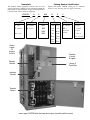
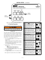
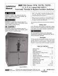
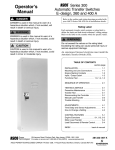
Operator’s
Manual
7000 Series 7ADTB
Automatic Delayed–Transition Transfer
& Bypass–Isolation Switches
H design 600 through 1200 amp.
DANGER is used in this manual to warn of high
voltages capable of causing shock, burns, or death.
WARNING is used in this manual to warn
of possible personal injury.
Refer to the outline and wiring drawings provided
with your 7000 Series ADTB for all installation and
connection details and accessories.
Refer to Group 5 Controller User’s Guide 381333–126
for ATS status display messages, time delays, pickup
& dropout settings, and adjustments.
An experienced licensed electrician must install the
7ADTB.
CAUTION is used in this manual to warn
of possible equipment damage.
Rating Label
Each 7000 Series 7ADTB contains a rating label to
define the loads and fault circuit withstand/closing
ratings. Refer to the label on the Transfer Switch for
specific values.
Do not exceed the values on the nameplate/
rating label. Exceeding the rating can cause
personal injury or serious equipment damage.
TABLE OF CONTENTS
section-page
INSTALLATION
Mounting . . . . . . . . . . . . . . . . . . . . . . . . . . . . . 1-1
Power Connections . . . . . . . . . . . . . . . . . . . . 1-1
Engine Starting & Auxiliary Circuits . . . . . . 1-2
Functional Test . . . . . . . . . . . . . . . . . 1-2, 1-3, 1-4
TESTING & SERVICE
Transfer Test . . . . . . . . . . . . . . . . . . . . . . . . . .
Preventive Maintenance . . . . . . . . . . . . . . . .
Disconnecting the Controller . . . . . . . . . . . .
Manual Load Transfer . . . . . . . . . . . . . . . . . .
Trouble-Shooting . . . . . . . . . . . . . . . . . . . . . .
2-1
2-1
2-1
2-2
2-2
BYPASSING & ISOLATING
Bypassing the ATS . . . . . . . . . . . . . . . . . 3-1, 3-2
Isolating the ATS . . . . . . . . . . . . . . . . . . . 3-3, 3-4
Return to Service . . . . . . . . . . . . . . . 3-5, 3-6, 3-7
INDEX . . . . . . . . . . . . . . . . . . . . . . . . . back cover
600–1200 amp. sizes
50 Hanover Road, Florham Park, New Jersey 07932–1591 USA
For sales or service call 1 800 800–2726 (ASCO) www.ascopower.com
ASCO POWER TECHNOLOGIES CANADA PO Box 1238, 17 Airport Road, Brantford, Ontario, Canada N3T 5T3
telephone 519 758–8450, fax 519 758–0876, for service call 1 888 234–2726 (ASCO) www.asco.ca
381333–195 A
Nameplate
Catalog Number Identification
The Transfer Switch nameplate includes data for each
specific 7000 Series 7ADTB. Use the switch only within the
limits shown on this nameplate. A typical Catalog Number
is shown below with its elements explained.
Typical 7000 Series 7ADTB catalog no. for switched
neutral, 3 pole, 600 amp, 480 V, in Type 1 enclosure:
H7ADTB
Neutral
A – solid
B – switched
blank – none
Status
Lights
&
Engine
Control
Bypass
Handle
B
Phase Poles
2 – single Ø
3 – three Ø
3
600
Amperes
600
800
1000
1200
N
5
Voltage
C 208
D 220
E 230
F 240
G 277
H 380
J 400
K 415
L 440
M 460
N 480
P 550
Q 575
R 600
C
Controller
5 – standard
5X – if
accessories
ordered
Enclosure
C – type 1
F – type 3R
G – type 4
L – type 12
blank – open type
Transfer
Control
& Lights
Group 5
Controller
Isolation
Handle
Transfer
Switch
open–type H7ADTB with the lower door open (transfer switch shown)
SECTION 1
INSTALLATION
Testing Power Conductors
ASCO 7000 Series Automatic Delayed–Transition
Transfer & Bypass–Isolation Switches (7ADTBs) are
factory wired and tested. Field installation requires
mounting and connection of service cables, and auxiliary
control circuits (if required).
Do not connect the power conductors to the transfer
switch until they are tested. Installing power cables in
conduit, cable troughs and ceiling-suspended hangers
often requires considerable force. The pulling of cables
can damage insulation and stretch or break the
conductor’s strands. For this reason, after the cables are
pulled into position, and before they are connected, they
should be tested to verify that they are not defective or
have been damaged during installation.
Remove the Shipping Skid
Open the front door and remove the four lag screws (2 in
front, 2 in rear) securing enclosure to the shipping skid.
Protect the switch from construction grit
and metal chips to prevent malfunction or
shortened life of the 7ADTB switch.
Supporting Foundation
The supporting foundation for the enclosure must be
level and straight. Refer to the applicable enclosure
outline drawing included with the switch for all mounting
details including door opening space.
Connecting Power Conductors
After the power cables have been tested, connect them to
the appropriate terminal lugs on the bypass switch as
shown on the wiring diagram provided with the switch.
Make sure the lugs provided are suitable for use with the
cables being installed. Standard terminal lugs are solderless screw type and will accept the wire sizes listed on the
drawings provided with the 7ADTB. Be careful when
stripping insulation from the cables; avoid nicking or
ringing the conductor. Remove surface oxides from
cables by cleaning with a wire brush. When aluminum
cable is used, apply joint compound to conductors.
Tighten cable lugs to the torque specified on rating label.
If bottom cable entry is used, the foundation must be
prepared so that the conduit stubs are located correctly.
Refer to the enclosure outline drawing for specified area
and location. Provide cable bending space and clearance
to live metal parts. When a concrete floor is poured, use
interlocking conduit spacer caps or a wood or metal
template to maintain proper conduit alignment.
Mounting
Refer to the applicable enclosure outline drawing furnished with this switch and mount the automatic transfer
switch according to details and instructions shown on
diagram.
Controller Ground
A grounding wire must be connected to the controller’s
lower left mounting stud. Because the controller is
mounted on the enclosure door, a conductive strap must
be used between the enclosure and the door. This
connection provides proper grounding which does not
rely upon the door hinges.
Line Connections
Refer to the Wiring Diagram provided with the switch.
All wiring must be made in accordance with the National
Electrical Code and local codes.
Do not remove the interphase barriers from the transfer
switch. Always protect the transfer switch, bypass switch,
and isolation contacts and mechanisms from construction grit and metal chips when cabling.
Harnesses
The transfer switch is connected to the left side of the
controller by a plug–in harness (two plugs).
De–energize the conductors before making any
line or auxiliary circuitry connections. Be sure
that Normal and Emergency line connections
are in proper phase rotation. Place engine generator starting control in the OFF position. Make
sure engine generator is not in operation.
1---1
INSTALLATION (continued)
Engine Starting Contacts
All customer connections, including the engine control
contact connections, are located on terminal block TB
which is mounted on the top right side of the enclosure.
Refer to the wiring diagram provided with the automatic
transfer switch and connect the engine start wires to the
appropriate terminals. See Figure 1–1 and Table A.
Table A. Engine start connections.
When normal source
fails
contact closes
contact opens
Terminals on
Terminal Block TB
TB1 and TB2
TB1 and TB3
engine start
connections
on
customer
terminal
block TB
Note: To temporarily disable engine control from
the automatic transfer switch you can unplug J3
from the small P3 receptacle at the bottom of the
assembly. Be sure to reconnect plug J3 to the P3
receptacle for automatic transfer switch operation.
Auxiliary Circuits
Connect auxiliary circuit wires to appropriate terminals
on transfer switch terminal block TB as shown on the
wiring diagram provided with this automatic transfer
switch.
Figure 1-1. Customer terminal block on the top right
side of the enclosure.
Functional Test
Read all instructions on the Wiring Diagram and labels
affixed to the automatic transfer & bypass–isolation
switch. Note the control features that are provided and
review their operation before proceeding.
The Functional Test consists of two checks:
❐ 1 — Voltage Checks, page 1–3
❐ 2 — Electrical Operation, page 1–4
Continue to 1 – Voltage Checks on next page.
Do these checks in the order presented
to avoid damaging the 7ADTB.
1---2
INSTALLATION (continued)
GREEN
RED
GREEN
RED
observe
these lights
AMBER
Figure 1-2. Standard controls and indicators.
Close the normal source circuit
breaker. The Transfer Switch
1 Connected To Normal and the
Normal Source Accepted lights
should come on.
Functional Test
Read all instructions on the Wiring Diagrams and labels
affixed to the 7ADTB. Note the control features that are
provided and review their operation before proceeding.
Load
Disconnect
Active
Use an accurate voltmeter to
check phase to phase and
2 phase to neutral voltages present at the transfer switch normal
source terminals.
After installing the 7ADTB check the following:
– Bypass Handle should be in the NORMAL position.
– Isolation Handle should be in the CONN position.
– CN transfer switch should be C (closed)
– CE transfer switch should be O (open)
Close the emergency source
circuit breaker. (Start generator,
if necessary.) The Transfer
3
Switch Connected To Normal &
Emergency Source Accepted
lights should come on.
If handles are not in correct positions, follow instructions
for Bypassing and Isolating the automatic transfer switch
in Section 3. Do not force the handles. Electrical
interlocks prevent a wrong sequence of operation.
Load
Disconnect
Active
Use an accurate voltmeter to
check phase to phase and
4 phase to neutral voltages present at the transfer switch emergency source terminals.*
1 – Voltage Checks
First check nameplate on transfer switch; rated voltage
must be the same as normal and emergency line voltages.
Use a phase rotation meter to
check phase rotation of emer5
gency source; it must be the
same as the normal source.
Use extreme caution when using a meter
to measure voltages. Do not touch power
terminals; shock, burns, or death could result !
Perform steps 1–6 at the right. Observe the status lights.
See Figure 1–2.
■ Black square means light is on.
❐ White square means light is off.
Shut down the engine–generator, if applicable. The Emergency Source Accepted light should
6 go off. Then put the starting
control selector switch (on the
generator set) in the automatic
position. Close enclosure door.
* If necessary, adjust voltage regulator on generator per the
manufacturer’s recommendations. The 7ADTB will respond only
to rated voltage specified on the nameplate.
Now continue to 2 – Electrical Operation on next page.
1---3
A B C
Load
Disconnect
Active
INSTALLATION (continued)
GREEN
RED
GREEN
RED
operate
this switch
observe
these lights
AMBER
Figure 1-3. Standard controls and indicators.
Turn and hold Transfer Control
switch clockwise to Transfer
Test until the engine starts
1
and runs (within 15 sec.). The
Emergency Source Accepted
light should come on.
2 – Electrical Operation
This procedure checks electrical operation of the ADTS.
Close enclosure door before proceeding to prevent
personal injury in case of electrical system fault.
Transfer switch CN opens and
the Transfer Switch Connected
to Normal light should go off
2
and the Load Disconnect Active
light should come on. Both CN
& CE contacts are now open.
Transfer Test
The ATS should still be bypassed. Both normal and
emergency sources must be available and the emergency
source generator (if used) must be capable of being
started; put engine starting control in automatic position.
The Transfer Switch Connected to Normal light and the
Normal Source Accepted light should be on.
1.
After the delay transition time
delay, the CE Transfer switch
will operate to the Emergency
3 position. The Transfer Switch
Connected To Emergency light
should come on and Load Disconnect Active light goes off.
Transfer switch will operate
back to Normal position after
Feature 3A time delay. For immediate retransfer turn Transfer
Control counterclockwise to
4
Retransfer Delay Bypass. The
Transfer Switch Connected To
Normal light should come on;
Transfer Switch Connected to
Emergency light should go off.
Turn the Isolation Handle counterclockwise to the
TEST position.
NOTE: The engine generator may be signalled to start while
turning the Isolation Handle. If emergency source is available,
the ATS may operate to the emergency position. If it does,
operate Retransfer Delay Bypass switch.
2.
Perform steps 1–5 at right. Observe the status lights.
See Figure 1–3.
■ Black square means light is on.
❐ White square means light is off.
3.
Turn the Isolation Handle clockwise to the CONN
(connected) position.
4.
Turn Bypass Handle clockwise to the OPEN position.
The engine–generator will stop
after the Feature 2E time delay
5 (unloaded running engine cooldown). The Emergency Source
Accepted light should go off.
This completes the Functional Test of the 7ADTB.
1---4
Load
Disconnect
Active
Load
Disconnect
Active
Load
Disconnect
Active
Load
Disconnect
Active
Load
Disconnect
Active
SECTION 2
TESTING & SERVICE
TRANSFER TEST
REPLACEMENT PARTS
Test the Automatic Transfer Switch portion of the 7000
Series 7ADTB at least once a month. This procedure
checks the electrical operation of the Transfer Switch and
Controller. Put the engine–generator starting control (at
the engine–generator set) in automatic mode.
Replacement parts are available in kit form. When ordering parts provide the Serial No., Bill of Material No.
(BOM), and Catalog No. from the transfer switch nameplate. Contact your local ASCO Power Technologies
Sales Office or ASI:
In the following test the generator will start, the load will
be transferred to the Emergency source, then back to the
Normal source. An interruption to the load will occur, unless the the Transfer Switch contacts are bypassed before
the test. See pages 3–1 through 3–4 for bypassing & isolating instructions if no interruption of load is required.
In the United States
call 1 – 800 – 800 – ASCO ( 2726 )
In Canada
call 1 – 888 – 234 – ASCO ( 2726 )
DISCONNECTING THE CONTROLLER
The harness disconnect plugs are furnished for repair
purposes only and should not have to be unplugged. If
the controller must be isolated, follow these steps:
Be sure to close the enclosure door
before proceeding to prevent personal injury
in case of electrical system fault.
Perform the five–step Electrical Operation – Transfer
Test procedure on page 1–4.
PREVENTIVE MAINTENANCE
Reasonable care in preventive maintenance will insure
high reliability and long life for the 7000 Series 7ADTB.
An annual preventive maintenance program is recommended.
Bypass–Isolation Switch is energized!
Do not touch isolation contact fingers;
shock, burns, or death could result!
Disconnecting the Plugs
1. Bypass and Isolate the Automatic Transfer Switch.
2. Open the upper enclosure door.
3. Separate the two quick disconnect plugs by squeezing the latches. Do not pull on the harness wires.
ASCO Services, Inc. (ASI) is ASCO Power
Technologies’s national service organization. In the
US ASI can be contacted at 1-800-800-2726 for information on preventive maintenance agreements.
Reconnecting the Plugs
1. The ATS should be still bypassed and isolated.
Checklist for Yearly Inspection
2. The two harness plugs and sockets are keyed. Carefully align the plugs with the sockets and press
straight in until the latches click.
Hazardous voltage capable of causing shock,
burns, or death is used in this switch.
Deenergize both Normal – Emergency power
sources before performing inspections!
3. Close the enclosure doors.
4. Follow Return to Service instructions on page 3–5.
❐ Clean the 7ADTB enclosure.
Brush and vacuum away any excessive dust accumulation. Remove any moisture with a clean cloth.
❐ Check the transfer switch contacts.
Bypass, isolate, and withdraw the transfer switch.
Then remove the transfer switch interphase barriers
and check the condition of the contacts. Replace contacts when pitted or worn excessively. Reinstall the
interphase barriers carefully. See page 3–4.
❐ Maintain transfer switch lubrication.
If switch is subjected to severe dust or abnormal
operating conditions, renew factory lubrication on
all movements and linkages. Relubricate solenoid
operator if TS coil is replaced. Don’t use oil; order
lubrication kit 75-100.
❐ Check all cable connections & retighten them.
2---1
MANUAL LOAD TRANSFER
This procedure manually transfers load to other source if
the Transfer Switch or Controller are out of service.
Close enclosure doors to prevent personal
injury in case of electrical system fault.
1. Bypass the connected 7ADTB source. Turn Bypass
Handle to EMERGENCY or NORMAL (see page
3–2).
2. Isolate to Test. Turn the Isolation Handle to TEST
position (see page 3–3).
3. Turn the Bypass Handle to OPEN, then to the other
source (see page 3–1). The load will be interrupted.
4. Turn the Isolation Handle clockwise to the CONN
[connected] position (see page 3–4).
TESTING & SERVICE (continued)
TROUBLE-SHOOTING
Note any optional accessories that may be furnished on
the 7ADTB and review their operation. Refer to any
separate drawings and/or instructions that may be packed
with the 7ADTB. See Table B.
Hazardous voltage capable of causing shock,
burns, or death is used in this switch.
Do not touch the power or load terminals
of the bypass switch or transfer switch!
Table B. Trouble-Shooting Checks.
PROBLEM
Engine–generator set does
not start when the Transfer
Control switch is turned and
held in Transfer Test position
or when normal source fails.
CHECK IN NUMERICAL SEQUENCE
1 OPERATION
2 GEN-SET
Hold Transfer Test switch 15
Starting control must be in the
seconds or the outage must
automatic position. Batteries
be long enough to allow for
must be charged and
Feature 1C time delay plus
connected. Check wiring to
engine cranking and starting. engine starting contacts.
3 VOLTAGE
---
Transfer switch does not
transfer the load to the
emergency source after the
engine–generator set starts.
Wait for Feature 2B time delay Generator output circuit
breaker must be closed.
to time out.
Generator frequency must be
at least 95% of nominal (57 Hz
for a 60 Hz system.) *
Voltmeter should read at least
90% of nominal phase to
phase voltage between
terminals EA and EC (or EL1
and EL2 for 2 pole switches)*
Transfer switch does not
transfer the load to normal
source when normal returns
or when the Transfer Control
switch is released.
Wait for Feature 3A time delay
to time out.
Voltmeter should read at least
90% of nominal phase to
phase voltage between
terminals NB and NC, NC and
NA, and NA and NB (or NL1
and NL2 for 2 pole switches).
Gen. does not stop after load
retransfer to normal source.
Load Disconnect Active light
comes on.
Load Disconnect Active light
stays on longer than 6 min.
Wait for Feature 2E time delay
to time out.
Wait for load disconnect time
delay to time out.
Check load disconnect time
delay setting. Call ASI.
---
Starting control must be in the
--automatic position.
Explanation: Transfer switch in delayed transition transfer mode.
Load disconnect time delay is adjustable from 0 to 5 min. 59 sec.
Explanation: Transfer switch contacts are open longer than 5
min. 59 sec (maximum setting). Load remains disconnected.
* These are factory settings. Refer to Controller’s User’s Guide.
If the problem is isolated to circuits on the controller or the transfer switch, call your local ASCO Power Technologies
sales office or ASI: in the United States, call 1–800–800–2726 or in Canada call 1–888–234–2726. Furnish the Serial No.,
Catalog No., and Bill of Material (BOM) No. from the transfer switch nameplate.
MAINTENANCE HANDLE
Emergency contacts
(upper shaft)
Bypass and isolate the Transfer Switch before
using the maintenance handle! See pages
3–1 through 3–4. Remove the maintenance
handle after using it; store it inside.
1.
2.
Bypass, isolate, and withdraw the transfer switch
(pages 3–1 through 3–4). Then locate and remove the
maintenance handle from the clip (inside lower left
side). Insert the handle onto the shaft on the left side
of the operator of the transfer switch See Figures
2–1, 2–2, 2–3 and Table C.
Move the maintenance handle up or down as shown
to manually operate the transfer switch. Operate
both upper and lower contact shafts. Observe the
window indicators (right side). Remove the maintenance handle and store it on the lower left side.
2---2
window indicators
O is open
C is closed
contact
position
indicators
(right side)
Normal contacts
(lower shaft)
Figure 2–1. Contact position indicators.
Note: If Normal and Emergency connections are
reversed this operation is also reversed.
TESTING & SERVICE (continued)
handle
UP opens the
Emergency source
contacts
frame
UPPER SHAFT
DOWN closes the
Emergency source
contacts
shaft
Figure 2–2. Maintenance handle operation for Emergency source contacts (upper shaft).
handle
UP closes the
Normal source
contacts
frame
LOWER SHAFT
DOWN opens the
Normal source
contacts
shaft
Figure 2–3. Maintenance handle operation for Normal source contacts (lower shaft).
Transfer Switch Position
Table C. Maintenance handle positions.
Interlocked Weights
Lobes prevent closing Maintenance Handle
both N & E contacts
up
weight
shaft
E=O
E
upper contacts open
lobe
Normal
Shaft Indicators
lobe
N
up
shaft
N=C
lower contacts closed
weight
up
Load
Disconnected
E=O
E
upper contacts open
N=O
N
lower contacts open
down
E=C
E
down
Emergency
upper contacts closed
N=O
N
lower contacts open
down
2---3
SECTION 3 BYPASSING & ISOLATING
BYPASSING THE ATS*
This procedure explains how to Bypass the closed
transfer switch contacts. Bypassing is required before the
Transfer Switch can be tested or isolated. The Bypass
Switch Handle must be in the OPEN position (green
window indicator) and the Isolation Handle must be in
the CONN [connected] position (window indicator). The
TS Connected light must be on. See Figures 3–1, 3–2, 3–3.
You can only bypass to the same source
that the Transfer Switch is connected.
Solenoid interlock prevents incorrect operation.
1.
Observe which Transfer Switch Connected To light is
on (Normal or Emergency) on the door. This is the
position of the transfer switch (see Figure 3–2).
2.
Follow the directions on next page to Bypass to the
same source as connected to transfer switch (select
Normal or Emergency).
Window indicator
shows yellow
when ATS is
bypassed to
Emergency.
Window indicator
shows green when
the ATS is not
bypassed.
Figure 3–1. Status lights and Engine Control.
Upper green light is on
if Transfer Switch is on
Normal.
Lower red light is on if
Transfer Switch is on
Emergency.
TRANSFER SWITCH
Window indicator
shows yellow
when ATS is
bypassed to
Normal.
CONNECTED TO NORMAL
Figure 3–4. Bypass Handle and
three position window indicators.
CONNECTED TO EMERGENCY
Figure 3–2. Status lights for Transfer Switch main
contact position.
Upper amber light
should be on.
Allowable Positons of the Bypass Switch
in relation to Positons of the Transfer Switch
(with Isolation Handle in the Conn [connected]
positon and TS Connected light on)
TS CONNECTED
Transfer Switch
TS TEST
If Transfer Switch is in
Normal position.
If Transfer Switch is in
Emergency position.
TS ISOLATED
Figure 3–3. Status lights for Transfer Switch isolation
contact position.
3---1
Bypass Switch
can be in either
Open or
Normal
Open or
Emergency
BYPASSING & ISOLATING
To Bypass Normal Source*
(Load connected to Normal Source)
The Transfer Switch Connected To Normal light is on
and Transfer Switch Connected To Emergency light is off.
(Load connected to Emergency Source)
The Transfer Switch Connected To Emergency light is on
and Transfer Switch Connected To Normal light is off.
Push in the handle and
turn it counterclockwise.*
Turn the handle clockwise.*
Push in* the Bypass Handle all the way, then turn it
counterclockwise until Bypass Switch Position shows
closed on NORMAL (yellow window indicator). The
green light Bypassed to Normal will come on and the
amber light Not In Automatic will flash.
Push in
Bypass
Handle
and
turn it
counterclockwise.
(continued)
To Bypass Emergency Source*
Bypass Switch
Turn* the Bypass Handle clockwise until Bypass Switch
Position shows closed on EMERGENCY (yellow window
indicator). The red light Bypassed to Emergency will come
on and the amber light Not In Automatic will flash.
E
Bypass Switch
Turn
Bypass
Handle
clockwise.
L
L
N
N
ATS
ATS
Figure 3–5. Bypass to Normal diagram.
Upper green
light comes on
E
Figure 3–7. Bypass to Emergency diagram.
BYPASS SWITCH
BYPASS SWITCH
BYPASSED TO NORMAL
BYPASSED TO NORMAL
Lower red
light comes on
BYPASSED TO EMERGENCY
BYPASSED TO EMERGENCY
Upper window indicator
EMERGENCY shows yellow
Lower window indicator
NORMAL shows yellow
Figure 3–6. Status light and window indicator for
Figure 3–8. Status light and window indicator for
Bypassed to Normal Source.
Bypassed to Emergency Source.
The automatic transfer switch can now be put in the TEST or OPEN position. See ISOLATING on page 3–3.
* NOTE: When Accessory 40*B (reversed Normal & Emergency connections)
is specified, the handle operation is reversed. Follow instructions on the door.
3---2
BYPASSING & ISOLATING
ISOLATING THE ATS
Isolating is required before any service work can be
performed on the automatic transfer switch (ATS). Refer
to Figures 3–9, 3–10, 3–11, and 3–12.
Hazardous voltage capable of causing
electrical shock, burns, or death;
do not touch any control circuit terminals.
1. Bypass the closed automatic transfer switch contacts.
See BYPASSING on pages 3–1 and 3–2.
2. Turn the Isolation Handle counterclockwise (approx.
8 turns) until window shows TEST. The TS Test amber
light should come on. The ATS can be tested now
without load interruption (see page 2–1).
Bypass Switch
Turn crank
counterclockwise
until
window
shows
TEST.
(continued)
NOTE: In the TEST position the transfer
switch solenoid operator circuit is energized
through secondary disconnects.
3. Continue turning Isolation Handle counterclockwise
(approx. 6 turns) until the window shows ISOLATE.
The TS Isolated amber light should come on.
Bypass Switch
E
Turn crank
counterclockwise
until
window
shows
ISOLATE.
L
L
N
N
Automatic Transfer Switch
Automatic Transfer Switch
Figure 3–11. TEST to ISOLATE position.
Figure 3–9. CONNECTED to TEST position.
Middle amber light
should be on.
E
TS CONNECTED
TS CONNECTED
TS TEST
TS TEST
Lower amber light
should be on.
TS ISOLATED
TS ISOLATED
CONN
counterclockwise – draws
TEST
out the transfer switch
ISOLATE
Figure 3–12. Isolation Handle turned to ISOLATE.
CONN
counterclockwise – draws
TEST
out the transfer switch
ISOLATE
Figure 3–10. Isolation Handle turned to TEST.
position
window
position
window
3---3
BYPASSING & ISOLATING
4. Open the lower enclosure door. Pull out both left and
right side rails then use the two handles to roll out the
transfer switch. It can be safely inspected in this
position. The transfer switch can also be removed for
easier maintenance operations. See Figure 3–13.
(continued)
To prevent the possibility of fatal electrical
shocks and burns, bypass, isolate, and withdraw
the transfer switch before working on it.
The contact assemblies (two for each pole) are
located to the right of the operator mechanism.
Hazardous voltage capable of causing
electrical shock, burns, or death;
do not touch any control circuit terminals.
1. Deenergize transfer switch (pages 3–1 thru 3–4)
Bypass, isolate, and withdraw transfer switch.
Use a voltmeter to verify that no electrical
power is present at the transfer switch terminals.
2. Use the maintenance handle (page 2–2).
Open the contacts that will be inspected by using
the detachable maintenance handle.
3. Remove the interphase barriers (Figure 3–14).
Use a blade screwdriver to loosen (ccw) four
round–head screws holding each barrier to the
arc chutes. Slide barrier up until keyholes clear
the round–head screws, then remove it.
handles
arc chutes
left rail
loosen (ccw)
round–head screws
(do not remove)
right rail
Figure 3–13.Transfer switch isolated
and pulled out for inspection.
See page 2–2 for maintenance handle use. A lifting yoke
734408 is available to facilitate lifting by using an
overhead crane or similar equipment. See WARNING.
keyslots
The Transfer Switch weighs 165–235 lbs.
depending upon the number of poles. Use lifting
device 734408 or other device capable of lifting
this weight to avoid personal injury or equipment
damage. Two persons are recommended.
interphase barrier
loosen (ccw)
round–head screws
(no not remove)
Contact Inspection
The main contacts are protected by arcing contacts.
The arcing contacts make first and break last to
avoid arcing at the main contacts. Contact condition
should be checked annually. Contacts should be
replaced when contact material becomes severely
worn. Discoloration is normal. Do not file contacts
because it wastes material. Instead use light emery
paper to clean up the contact surfaces.
keyslots
insulator nuts
Figure 3–14. Interphase barrier removal.
4. Remove the arc chutes.
Use a 5/8” nutdriver to remove (ccw) two long
insulator nuts. Then pull the arc chute outward
(off the long threaded rods). See Figure 3–14.
If the contacts need to be replaced see page 2–2.
3---4
BYPASSING & ISOLATING
5. Remove the movable contact cover.
Use your thumb and fingers to squeeze the sides
inward until the contact cover is released from the
shaft clamp (both sides). Then remove the
movable contact cover. See Figures 3–15 & 3–16.
(continued)
RETURN TO SERVICE
This procedure explains how to return the automatic
transfer switch (ATS) to service after inspection and
maintenance. Observe the Bypass Switch Position indicator and lights).
1. Use the two handles to roll the transfer switch into
the enclosure (isolation contacts facing inward) until
its crank pins engage the latch plates on both sides.
Next push in both side rails and close enclosure door.
s queeze movable
contact cover to
releas e it
handles
Figure 3–15.
Movable contact
cover release.
shaft clamp
right rail
left rail
movable contact cover
Figure 3–17.Transfer switch isolated
and pulled out for inspection.
Figure 3–16. Movable
contact cover removal.
Close the enclosure door to prevent personal
injury in case of electrical system fault.
2. Turn Isolation Handle clockwise (approx. 6 turns) until
the window shows TEST and TS TEST light comes on.
6. Reinstall the movable contact cover.
After inspection reinstall the movable contact
cover onto the movable contact assembly. Use
your thumb and fingers to squeeze the sides
inward until the contact cover is latched onto the
metal bracket (both sides). Figures 3–15 & 3–16.
Bypass Switch
E
Turn crank
clockwise
until
window
shows
TEST.
7. Reinstall the arc chute.
Slide the arc chute (arc splitters toward the
contacts and recess for nuts outward) between the
two long threaded rods. Reinstall the two long
insulator nuts (round shoulder in) and use a 5/8”
nutdriver to GENTLY tighten (cw) until snug. Do
not overtighten these nuts. See Figure 3–14.
L
N
8. Reinstall the interphase barrier.
Install the barrier over the arc chutes and slide
it up until the four round–head screws align in the
four keyholes in the barrier. Then slide the barrier
down. Use a blade screwdriver to tighten (cw) the
four round–head screws to secure the barrier to
the arc chute insulator nuts. See Figure 3–14.
Automatic Transfer Switch
Figure 3–18. ISOLATE to TEST position.
3---5
BYPASSING & ISOLATING
Do not close the isolation contacts unless
the Transfer Switch (ATS) and Bypass
Switch are in the same position!
TS CONNECTED
Middle amber light
should come on.
(continued)
TS TEST
TS ISOLATED
6. When the transfer switch is in the same position as
the Bypass Switch handle, continue turning the
Isolation Handle clockwise (about 8 turns) until the
window shows CONN (connected).
Bypass Switch
Turn crank
clockwise
until
window
shows
TEST.
position
window
TEST
E
L
clockwise – draws in
the transfer switch
N
Figure 3–19. Isolation Handle turned to TEST.
3. The ATS can be tested now without load interruption
(see page 2–1).
Automatic Transfer Switch
Figure 3–20. TEST to CONN (connected) position.
Upper amber light
should be on.
Solenoid interlock prevents you from closing
the isolation contacts until the ATS is in the
same position as the Bypass Switch.
TS CONNECTED
TS TEST
4. Observe which Bypass Switch Position window indicator is yellow (NORMAL or EMERGENCY) at the
Bypass Switch Handle. This indicates the source
connected to the load.
5. Observe which Transfer Switch Connected To light is
on (Normal or Emergency) on the door. This is the
position of the Transfer Switch. If it is not in the same
position as the Bypass Handle change the position of
the Transfer Switch as follows:
TS ISOLATED
To change the position of transfer switch
Operate to NORMAL
Turn Transfer Control
switch to Retransfer
Delay Bypass.
Connected To Normal
light should come on.
Operate to EMERGENCY
Turn Transfer Control
switch to Transfer Test
(hold 15 seconds).*
Connected To Emergency
light should comes on.
CONN
position
window
* If Feature 2B time delay is used, there will be a delay
before transfer to Emergency.
CONN
clockwise – draws in
the transfer switch
Figure 3–21. Isolation Handle turned to CONN.
NOTE: With Normal available, the automatic transfer
switch will not stay in the emergency position unless
Feature 3A time delay is used (at least 30 seconds).
3---6
BYPASSING & ISOLATING
RETURN TO SERVICE continued*
(continued)
Indicator shows
yellow when ATS
is bypassed to
Emergency.
This procedure explains how to return the Bypass Switch
Handle to the OPEN position. The Bypass Handle must
be in the CLOSED position (yellow indicator on NORMAL or EMERGENCY) and the Isolation Handle must
be in the CONN position (window). See Figures 3–22,
3–23, and 3–24.
Indicator shows
green when the ATS
is not bypassed.
You can only bypass to the same source
that the ATS is connected. Solenoid
interlock prevents incorrect operation.
1
2
Observe which Bypass Switch Position indicator is
yellow (NORMAL or EMERGENCY) at the Bypass
Switch Handle. This indicates the source connected
to the load.
Un–Bypass to same source as the Bypass Switch
Position as follows (select Normal or Emergency).
Indicator shows
yellow when ATS
is bypassed to
Normal.
Figure 3–22. Bypass Handle and position indicators.
To Un–Bypass Normal Source*
To Un–Bypass Emergency Source*
(Load connected to Normal Source)
The Transfer Switch Connected To Normal light is on
and Transfer Switch Connected To Emergency light is off.
(Load connected to Emergency Source)
The Transfer Switch Connected To Emergency light is on
and Transfer Switch Connected To Normal light is off.
Turn the handle clockwise.*
Turn the handle counterclockwise.*
Turn* the Bypass Handle clockwise until the Bypass
Switch Position shows OPEN (green window indicator).
The Bypassed to Normal light should go off and the Not
In Automatic light should go off.
Turn
Bypass
Handle
clockwise.
Bypass Switch
Turn* the Bypass Handle counterclockwise until the
Bypass Switch Position shows OPEN (green window
indicator). The Bypassed to Emergency light should go off
and the Not In Automatic light should go off.
E
Turn
Bypass
Handle
counterclockwise.
L
Bypass Switch
E
L
N
N
ATS
ATS
Figure 3–23. Un–Bypass Normal diagram.
Figure 3–24. Un–Bypass Emergency diagram.
The Automatic Closed–Transition Transfer & Bypass–Isolation Switch should be left in this position.
* NOTE: When Accessory 40*B (reversed Normal & Emergency connections) is specified,
the handle push–pull operation is reversed. Follow instructions on the door.
3---7
INDEX
A
auxiliary circuits, 1–2
B
I
indicators, contact position, 2–2, 2–3
inspection, 3–1
installation, 1–1
barriers, interphase, 3–4, 3–5
interlocked weights, 2–3
bypassing the ATS, 3–1, 3–2
interphase barriers, 3–4, 3–5
isolating the ATS, 3–3, 3–4
C
L
catalog number, 1–1
lifting device, transfer switch, 3–4
cleaning, 2–1
lights, 1–2, 1–3, 3–1, 3–2, 3–3
connections
power, 1–1
load connected to emergency, 1–3
contact inspection, 3–4, 3–5
controller
disconnecting, 2–1
see Controller User’s Guide
D
delayed transition transfer, 1–4
see Controller User’s Guide
E
electrical operation, 1–4
Emergency Source Accepted light,
1–3
engine starting contacts, 1–2
F
foundation, 1–1
frequency, generator, 2–2
functional test, 1–2, 1–3, 1–4
H
R
rating label, cover
replacement parts, 2–1
return to service, 3–5, 3–6, 3–7
S
service
ASCO Services, Inc. (ASI), 2–1
settings
see Controller User’s Guide
load connected to normal, 1–3
Load Disconnect Active light, 1–4
lubrication, 2–1
M
maintenance, preventive, 2–1
T
test, functional, 1–2, 1–3, 1–4
testing power cables, 1–1
maintenance handle, 2–3
warning, 2–3
time delays, 2–1
see Controller User’s Guide
manual load transfer, 2–3
warning, 2–3
Transfer Control selector switch
Retransfer Delay Bypass, 1–3
Transfer Test, 1–3
N
nameplate, 1–1
Normal Source Accepted light, 1–3
O
operation
electrical, 1–4
manual, 2–3
warning, 2–3
optional accessories
see Controller User’s Guide
P
Transfer Switch Connected To
Emergency light, 1–3
Transfer Switch Connected To
Normal light, 1–3
transfer test, 1–4, 2–1
transfer to emergency, 1–4, 2–1
transfer to normal, 1–4, 2–1
troubleshooting, 2–2
V
harness, 1–2
disconnect plugs, 2–1
parts, 2–1
HELP
[email protected]
800–800–2726 (ASCO)
phase rotation check, 1–3
voltage checks, 1–3
preventive maintenance, 2–1
voltage, pickup and dropout settings
see Controller User’s Guide
Printed in U.S.A.
problem, 2–2
Copyright 2007 ASCO Power Technologies, L.P.