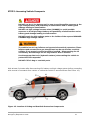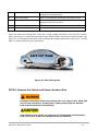
1
TM TM The all-electric car from an all-electric car company CODA 2012 TM Emergency Responder’s Guide Technical Assistance Center 888-718-5046 or [email protected] Copyright 2012 CODA Automotive, Inc. Information in this document is the confidential property of CODA Automotive, Inc. and, shall not be disclosed, disseminated, copied, duplicated, or used except for purposes authorized by contract or agreement or otherwise expressly authorized in writing. Products and services referred to in this document may be either trademarks and/or registered trademarks of the respective owners. CODA Automotive, Inc. makes no claim to these trademarks. The marks appearing on this document including, but not limited to: (i) CODA and the CODA Logo (circle within a circle); emblems, slogans and vehicle model names and body and battery designs are trademarks and/or service marks of CODA Automotive, Inc. For more information contact: CODA Automotive, Inc. 2340 S. Fairfax Avenue Los Angeles, CA 90016 1-855-GO4-CODA (1-855-464-2632) Twitter: @CODAAutomotive Table of Contents 1. ABOUT THIS MANUAL .................................................................................................. 1 INTRODUCTION .................................................................................................................... 1 IMPORTANT INFORMATION ABOUT THIS MANUAL .............................................................................. 1 2. ABOUT THE CODA VEHICLE .......................................................................................... 2 CODA Identification - Exterior Features ............................................................................. 2 Vehicle Identification Number (VIN) .................................................................................. 3 Interior Component Location ........................................................................................... 4 3. ELECTRICAL SYSTEM INFORMATION ............................................................................ 5 High Voltage and 12-Volt Component Locations and Descriptions ......................................... 5 High Voltage Safety Measures .......................................................................................... 7 4. ELECTRIC VEHICLE SAFETY RULES ............................................................................... 8 5. EMERGENCY PROCEDURE ............................................................................................. 9 STEP 1: ASSESS DAMAGE AND PREPARE EMERGENCY EQUIPMENT ..................................... 9 STEP 2: STABILIZE VEHICLE ........................................................................................ 11 STEP 3: DISCONNECT HIGH VOLTAGE BATTERY ............................................................. 13 High High High High High High Voltage Voltage Voltage Voltage Voltage Voltage System System System System System System Shutdown When Vehicle Is Connected to Charger .......................................... 15 Shutdown Sequence .................................................................................. 15 Shutdown- 12 Volt Disconnect ..................................................................... 16 Shutdown- Main Service Disconnect ............................................................. 17 Shutdown- Rear Service Disconnect ............................................................. 18 Shutdown- Front Power Distribution Box (FPDB) ............................................ 19 STEP 4: Thermal Event Containment ............................................................................. 20 STEP 5: Accessing Vehicle Occupants.............................................................................. 21 STEP 6: Remove the Vehicle and Secure Accident Site ...................................................... 22 Spare Tire Repair Kit Canister Cautions ...................................................................................... 23 Storing the CODA Vehicle ......................................................................................................... 23 Towing the CODA Vehicle .......................................................................................................... 23 Table of Contents Emergency Responder’s Guide i 1. About this Manual Introduction This manual describes first responder operations, related warnings and cautions for this vehicle. This vehicle is powered by a HIGH VOLTAGE battery pack. Improper contact with a high voltage battery pack or other high voltage components MAY RESULT in serious injury or DEATH. Please fully read this manual in advance to understand the technology of this vehicle and to help you safely respond to an incident involving this vehicle. Follow all warnings and procedures in order to help perform a safe and proper first responder operation. Important Information about this Manual This manual will have various symbols which are defined as: This symbol is used to inform you of a hazardous situation, which will result in death or serious personal injury if the enclosed instructions are not followed. EXAMPLE: Cutting the high voltage wires without properly following disconnection procedures will result in electrocution. This symbol is used to inform you of a hazardous situation which, could result in death or serious personal injury if the enclosed instructions are not followed. This symbol is used to inform you of a hazardous situation which, could result in minor or moderate injury if the enclosed instructions are not followed. * All specifications and descriptions are accurate at the time of printing. Because improvement is a constant goal at CODA Automotive, we reserve the right to make changes at any time, without notice and without obligation. This manual applies to all 2012 model year CODA vehicles. 1. About this Manual Emergency Responder’s Guide 1 2. About the CODA Vehicle TM CODA is a plug-in electric vehicle that uses two types of batteries: • High voltage traction battery – a 333-volt Lithium ion battery pack (Lithium Iron Phosphate technology) to power drive motor and other high voltage components. • Low voltage accessory battery - a standard 12-volt lead acid battery (Absorbed Glass Mat (AGM) technology) to power select vehicle electrical equipment. The high voltage battery pack is encased in an aluminum enclosure with a plastic cover and is mounted underneath the vehicle. The 12-volt battery is mounted in the rear trunk area next to right panel. CODA has two independent onboard chargers located under the rear cargo compartment. Chargers will accept 110 volts AC or 230 volts AC power via the J-1772 charging port located in the left rear of the vehicle. CODA Identification - Exterior Features Details on identifying the CODA are indicated below in Figure 1: 1 2 3 4 Figure 1: Location of Identification Features 1. CODA name placed on trunk deck lid left side 2. CODA emblem, placed on center of trunk and front grill 3. CODA All Electric emblem 4. Plug-in charge port left rear panel 2. About the CODA Vehicle Emergency Responder’s Guide 2 Vehicle Identification Number (VIN) The Vehicle Identification Number can be located in the lower left side of the dashboard as seen through the windshield. Example of the VIN numbering: 53G1U4A4XCBXXXXXX Figure 2: Location of Vehicle Identification Number Figure 3: Example of Vehicle Identification Number on dashboard The VIN is also displayed on the vehicle certification label on the driver’s side b-pillar. 2. About the CODA Vehicle Emergency Responder’s Guide 3 Interior Component Location Interior controls and locations in this manual are shown below in Figure 4: Figure 4: Interior Component Location 1. Instrument panel illumination 2. Exterior lights and turn signals 3. Instrument Panel 4. Wiper and Washer 5. Trunk release 6. Hazard warning flashers 7. Passenger Airbag status indicator 8. Touch-screen (Entertainment and navigation system) 9. Heating and Ventilation Controls 10.Gear selector 11.Starter switch 12.Steering column adjust 13.Horn 14.Hood release 15.Exterior mirror control 16. Power window control 2. About the CODA Vehicle Emergency Responder’s Guide 4 3. Electrical System Information High Voltage and 12-Volt Component Locations and Descriptions Main components of CODA’s electrical system are shown in Figure 5-7. Table 1 presents description of the components shown in Figure 5-7. High voltage battery specifications are shown in Table 2. Figure 5: High Voltage and 12-Volt Component Location 1. 2. 3. 4. 5. 6. 7. 8. 9. 10. 11. On-Board Chargers and DC/DC Converter J1772 Charge Port Rear Service Disconnect (RSD) High Voltage Cables ORANGE-COLORED Propulsion Inverter PTC Heater - Figure 6 High Voltage AC Compressor - Figure 6 12-Volt Accessory Battery Li-ion Battery Pack Main Service Disconnect (MSD) – Figure 7 Propulsion Motor 3. Electrical System Information Emergency Responder’s Guide 5 7 (AC Compressor), 6(PTC Heater) 10 (Main Service Disconnect) Figure 6 Figure 7 Table 1: Electrical System Components Component Location Description 1 On-Board Chargers and DC/DC Converter Rear compartment, floor pan area Two independent on-board chargers convert standard 110/220 volt AC wall plug power into DC power to charge the high voltage battery. The DC/DC converter reduces the voltage of the high voltage battery to provide power to the 12-Volt accessory components (i.e. headlights, radio, windows). 2 J1772 Charge Port Rear panel driver side This is the interface that connects the SAE J1772 standard charging connector to the vehicle. 3 Rear Service Disconnect (RSD) Inside vehicle, under rear seat cushion, under access panel The RSD will disconnect all systems from the Lithium ion battery pack. 4 High Voltage Cables (2) Run length of battery pack under floor pan. All high voltage harnesses are identified in orange. Cables carry high voltage (33 volts DC) from battery to high voltage components (i.e. chargers, inverter, DC/DC converter, AC compressor and PTC heater.) 5 Propulsion Inverter Motor compartment in holding fixture above Propulsion Motor The inverter generates a power signal to control speed and torque of the electric drive motor. 6 Positive Temperature Coefficient (PTC) Heater Under hood above AC Compressor This is a high voltage electric heat source in the system. It uses DC voltage to warm a high-current grid in the coolant stream. 7 High Voltage AC Compressor Under engine hood below Power train Control Module High voltage AC compressor for separate battery and cabin air conditioning 8 12-Volt Battery Rear of trunk on right side This is a 12-Volt battery (AGM-type) to provide power for accessories 9 Li-ion Battery Pack Under floor pan attached between front and rear suspension 3. Electrical System Information Emergency Responder’s Guide The Lithium ion battery has capacity of 31 kWh and nominal voltage of 333 Volts. This battery supplies power to the propulsion motor and high voltage components. 6 10 Main Service Disconnect (MSD) Under vehicle on the front of the battery pack This service disconnect plug is a high voltage interconnect loop and is used to manually disconnect the high voltage between the battery and the vehicle. High voltage is still present inside the battery pack even if the MSD is disconnected. 11 Propulsion Motor Under hood, mounted below high voltage inverter Permanent magnet brushless DC motor uses three-phase high voltage current to propel the wheels via transaxle. Table 2: Li-ion Battery Pack Specifications Nominal Voltage 333 Volts DC Number of modules 18 Total number of cells Pack Dimensions 624 W44” x L80” x H9” 893 lbs / 405 kg Weight High Voltage Safety Measures The following safety measures are implemented to help identify high voltage areas and to ensure safe handling of the high voltage battery pack: Table 3: HV Safety Measures Circuit insulation The high voltage Positive (+) and Negative (-) circuits are insulated from each other and from the metal chassis with dielectric materials rated at minimum 1000V. Reducing the risk of electrocution The high voltage components and harnesses have insulated cases or coverings. The high voltage battery pack assembly is installed to the vehicle body through mounting bolts. These bolts are electrically conductive between the battery pack insulated tray and vehicle chassis ground This connection helps protect the vehicle occupants and emergency responders from high voltage electrical shock. Identification The high voltage components are clearly labeled with DANGER or WARNING Labels. The high voltage components and harnesses have insulated cases or ORANGE-COLORED coverings to provide easy identification of high voltage presence. 3. Electrical System Information Emergency Responder’s Guide 7 4. Electric Vehicle Safety Rules The CODA vehicle is powered by a HIGH VOLTAGE electrical system. Failure to follow these instructions will result in death or serious injury from high voltage electrical shock. 1. Never attempt any repairs if you are not familiar with any of the affected systems or how electric vehicles operate. 2. Never approach or attempt any high voltage disconnects or repairs without Class O gloves, safety glasses/shield, non-synthetic clothing, and personal jewelry removed. 3. If it is necessary to touch any of the high voltage harnesses or components, wear the appropriate Personnel Protection Equipment (PPE) and shut off the high voltage by referring to “Step 3: Disconnect High Voltage Battery” on page 13. Never touch exposed wires at high voltage connectors. Only trained personal can repair these items. 4. To avoid the risk of electrocution, NEVER touch the inside of the Li-ion battery connector with bare hands even if you have disconnected the high voltage system. The Li-ion battery remains charged even if it is disconnected or if the high voltage system is shut down. 5. When high voltage connectors are disconnected always cover them with nonconductive insulated tape. Do not touch any exposed terminal. (See Figure 8) Figure 8: High Voltage Connector Protection 4. Electric Vehicle Safety Rules Emergency Responder’s Guide 8 5. Emergency Procedure STEP 1: ASSESS DAMAGE AND PREPARE EMERGENCY EQUIPMENT Before attempting any emergency procedures, verify that the high voltage battery is disconnected and use appropriate protective equipment (PPE). Failure to disable the high voltage electrical system before the Emergency Response Procedures are performed will result in serious injury or death from high voltage electrical shock. Read all other Danger and Warning messages in this manual before performing any of the Emergency Response procedures. The CODA is an electric vehicle powered by a high voltage battery. NEVER assume the CODA sedan is shut off because it is quiet. If it becomes necessary for the rescuer to leave the vehicle unattended, a placard or a sign stating “DANGER” or “HIGH VOLTAGE” should be placed on the vehicle to alert other people of this high voltage situation. Never work alone on or around a high voltage vehicle. Always alert others that you are working with a potential high voltage danger. Before touching the vehicle perform a visual inspection to assess the condition of the vehicle and its occupants: • Check if the vehicle is stable or requires stabilization to prevent it from rolling or collapsing. (See Step 2, page 11) • Check if the battery high voltage system is active by checking the vehicle dashboard for system readiness indicators. (See Figure 9) • Visually inspect the battery and high voltage components for signs of damage such as exposed high voltage wires (orange) or battery enclosure cracks or dents. • Visually inspect for signs of battery thermal event - hissing or popping sounds, small amounts of white smoke and acrid smell typical for electric fires. • Disconnect the high voltage battery. (See Step 3, page 13) If accessible, verify the READY or CHARGE indicator is off and the high voltage system is inoperable (See Figure 9). If the READY or CHARGE indicator on the dash is illuminated, the high voltage system is active in the vehicle. 5. Emergency Procedure Emergency Responder’s Guide 9 Battery Charge READY Indicator Lamp Figure 9: Location of READY and CHARGE Indicators READY Lamp Flashes green to indicate that the vehicle is performing pre-drive system checks. Illuminates continuously when the vehicle is in Drive mode and is ready to be driven. Charge Indicator Illuminates yellow to indicate that the vehicle is charging. The indicator will turn off when charging is completed. If a fault is detected, the indicator will turn off. 5. Emergency Procedure Emergency Responder’s Guide 10 Before beginning any work on the vehicle, ensure that you have the following PPE. Table 4: Preparation Items for Personal Protection Equipment (PPE) Preparation Items Specification Purpose Insulated Gloves 1,000 Volt rated To help protect responders from HIGH VOLTAGE electrical shock Insulated Shoes 1,000 Volt rated To help protect responders from HIGH VOLTAGE electrical shock Face Shield 1,000 Volt rated To help protect responders from HIGH VOLTAGE electrical ARC FLASH Wrenches Size: 10 mm To remove accessory battery cable terminal bolts/nuts Side Cutting Pliers Diagonal cut pliers To cut 12 Volt battery cables if terminal ends cannot be unbolted Heat-proof, Solvent-resistant protection gloves Heat-proof, Solvent resistant protection shoes Heat-proof, Solvent resistant protection tools To utilize in the event of an AGM or Li-ion battery damage event. Absorbent Pad The same type used for internal combustion engine spills To absorb any liquid leaks from transaxle or cooling system Extinguisher Type ABC, Type C, Type D To extinguish a variety of fires Insulated Tape (non-conductive) Insulating open connectors To cover the damaged harnesses to help protect from and prevent electrical shock. Tape should cover all bare or damaged wire connectors. STEP 2: STABILIZE VEHICLE Stabilize the vehicle to prevent further damage and danger to occupants and emergency personnel. 1. If the vehicle is submerged in water, remove the vehicle from water and completely drain before proceeding with subsequent emergency procedures. If possible, the driver’s key switch of the submerged vehicle MUST BE TURNED OFF. The vehicle must be completely emptied of any water to avoid electrical shock. DO NOT contact or touch the high voltage components or harnesses until the vehicle has been removed from the water and/or all water has been drained from the vehicle. Wear appropriate PPE before removing any service disconnect or handling high voltage harnesses and/or components or disconnecting 12V battery. 2. If possible, immobilize the vehicle by using one or more of the following: 5. Emergency Procedure Emergency Responder’s Guide 11 • Set the parking brake (Figure 10) Lift up on handle and firmly apply parking brake. Handle should move at least 6 clicks. Figure 10: Parking Brake • Use a minimum two wheel chocks of wooden blocks to prevent the vehicle from rolling. Do not stabilize the vehicle with wooden blocks under the Li-ion battery pack. To avoid electrical shock, do not put air lift equipment and wheel chocks under the high voltage components and harnesses. Lifting Vehicle lifting equipment should be placed under secure areas of the body. The CODA vehicle has a high voltage battery pack located under the vehicle. Incorrect stabilization or lifting procedures may damage the battery or high voltage cabling and cause risk for occupants or rescue personnel. Secure lift points on the front mount are approximately 8 inches from edge of fender opening. Secure lift points on rear mount are approximately 8 inches from front edge of rear wheel opening. Side trim panels have indentation arrows indicating lift point locations. The locations of lift points are shown in Figures 11 and 12. Figure 11 Locations of Lift Point 5. Emergency Procedure Emergency Responder’s Guide Figure 12: Locations of Lift Points 12 STEP 3: DISCONNECT HIGH VOLTAGE BATTERY Read and follow all Danger and Warning messages covered in Section 3“Electric Vehicle Safety Rules” before disconnecting the high voltage battery. Failure to disable the high voltage electrical system before the Emergency Response Procedures are performed will result in serious injury or death from high voltage electrical shock. NEVER APPROACH OR WORK ON HIGH VOLTAGE WITHOUT WEARING PPE. Failure to do will result in serious injury or death from high voltage electrical shock. DO NOT touch with bare hands any high voltage harnesses colored in ORANGE or high voltage components. High voltage can be present in the system for up to 2 minutes after shut-off. Wait at least 2 minutes after disconnecting high voltage before proceeding with emergency procedures. Do not attempt to reconnect any of the high voltage connection points if any arcing were to occur while disconnecting these components. After high voltage system shut down, there is a possibility that high voltage remains in the air conditioning system. Be sure the air conditioning system is turned off at the dash controls. The high voltage battery for the CODA vehicle is designed to shutdown automatically under certain events, such as airbag deployment, seat belt pretensioner deployment, and if the Battery Management System or Driveline Control Module detects a malfunction that deems the need to shut down the high voltage system. Even with these designs in place, the high voltage system should be treated as not shutdown when first responding and assessing the vehicle. High voltage shut down has to be performed before any first response operation. The high voltage system shutdown takes up to 2 minutes. Wait at least 2 minutes for total system shut-down before starting work on the vehicle. ALWAYS use appropriate PPE (insulated gloves, insulated shoes, and face shield) and observe high voltage safety rules before performing high voltage shutdown even if the READY and CHARGE lights are off and there is no visual damage to the battery. Table 5 summarizes several component used to shutdown the CODA’s high voltage system. Locations of main components of the vehicle high voltage shutdown system are shown in Figure 13. The choice of the shutdown method depends on the incident circumstances, vehicle position and shutdown device access. 5. Emergency Procedure Emergency Responder’s Guide 13 5 4 3 2 1 Figure 13 High Voltage Shutdown System – Component Location Table 5: High Voltage Shutdown System Components 1 High Voltage Interlock High Voltage In-Line (HVIL) interlock system is a continuous loop connecting all high voltage components. If any of the high voltage connectors are separated, the main high voltage battery relay opens, disconnecting the battery from the vehicle. High voltage is still present inside the battery pack, but all vehicle components are disconnected. 2 Main Service Disconnect (MSD) Positioned in the front center of the battery case. Removing the MSD plug opens the pack high voltage circuit. 3 Rear Service Disconnect (RSD) Rear Service Disconnect is located on top of battery pack on left side under rear seating area. Accessible from inside vehicle by removing rear seat cushion and access panel on floor. Unplugging the RSD will fully disconnect the system from the high voltage source. Important Note: This is the preferred and only full high voltage disconnect accessible with the vehicle on the ground. 4 Charging Connector (Electric Vehicle Service Equipment) EVSE Located on left rear quarter panel under charge door. Some high voltage components are activated when the EVSE plug is connected to charging system. Remove EVSE plug to deactivate these components. 5 12-Volt Battery Disconnect Located in right rear of storage area (trunk) next to right rear panel. If the 12V battery is disconnected, the high voltage battery main relays open disconnecting the battery from the vehicle. 5. Emergency Procedure Emergency Responder’s Guide 14 High Voltage System Shutdown When Vehicle Is Connected to Charger There are many manufacturers of Electric Vehicle Service Equipment (EVSE). For exact disconnect procedure follow specific manufacturer’s instructions. General instructions are: 1. 2. 3. 4. Press the unlock release button on lever on the J1772 charge connector handle. Pull the charge connector handle to remove it from charge port connector. Replace connector handle to EVSE charging station. Never place high voltage charge connector on ground. Avoid driving vehicle over charge cable. Figure 14: Charger Connector High Voltage System Shutdown Sequence The preferred sequence for High Voltage System shutdown is specified below. Crash severity, location of deformation, vehicle orientation, safety of occupants and first responders, and other variables may influence the ability to perform the High Voltage System shutdown in the following sequence. When the vehicle has been severely damaged and the Lithium ion battery has been deformed, broken, or appears to have been damaged in any way, appropriate Personal Protective Equipment (PPE), such as high voltage gloves rated at least 1000V and a face protection mask, must be used and the Lithium ion battery or high voltage components must not be touched. Even if the collision is minor and there is no visible damage to the battery and high voltage components, as a precaution the below sequence should be followed. Perform the following steps: 1. 2. 3. 4. 5. Turn vehicle off and remove key. The READY light should turn off. Disconnect or cut 12V battery cable in the trunk. Disconnect Main Service Disconnect (MSD) in the front middle of the battery pack under the front of the vehicle. Disconnect Rear Service Disconnect (RSD) under rear seat inside vehicle. Disconnect main high voltage cable connector at Front Power Distribution Box (FPDB) under the hood if MSD or RSD are not accessible. The FPDB is located under the hood. 5. Emergency Procedure Emergency Responder’s Guide 15 High Voltage System Shutdown- 12 Volt Disconnect Perform the following steps: Disconnect 12-Volt battery to disable airbag systems and shut-off high voltage battery. Disconnecting 12 volt battery in most cases will disconnect the high voltage battery, but it is possible that high voltage may still be present in the vehicle. Use proper PPE and observe the high voltage safety rules in this guide while disconnecting the 12V battery. 1. Locate the 12-volt battery in rear trunk compartment on the passenger side. 2. Disconnect the negative terminal or cut the negative terminal cable using insulated tools 3. Protect the battery terminal from contact with vehicle metal parts (use electrical tape or other dielectric material). If 12-volt battery cannot be reached, pull # 6 (10 amp) fuse in the under dash fuse panel. 4. No.6 fuse 10A 5. Emergency Procedure Emergency Responder’s Guide 16 5. Before proceeding with any emergency procedures including extrication of occupants, wait 2 minutes for high voltage and SRS system to fully power down. High Voltage System Shutdown- Main Service Disconnect Perform the following steps: 1. Unlatch the orange plastic cover on the skid plate to access the MSD. Connector Unlock Tool 2. Insert connector unlock tool. 3. Unplug the MSD plug. 4. Wait 2 minutes to ensure that the high voltage is fully disconnected. 5. Secure the battery connector terminals with electrical tape. 5. Emergency Procedure Emergency Responder’s Guide 17 High Voltage System Shutdown- Rear Service Disconnect Disconnecting the RSD is the only shutdown method that fully disconnects the vehicle from the high voltage battery. Perform the following steps: 1. Remove rear seat cushion. Remove 13mm mounting bolts Remove rear seat cushion 2. Remove access panel on the rear left floor. Remove the cover screws Open the cover 3. Unplug the Rear Service Disconnect plug. Insert tool to release tab Lift and pull latch handle Completely unplug connector Unplug HVIL connector Unplug rear power distribution box connector 4. Wait 2 minutes to ensure that the high voltage is fully disconnected. 5. Emergency Procedure Emergency Responder’s Guide 18 5. Secure the battery connector terminals with electrical tape. High Voltage System Shutdown- Front Power Distribution Box (FPDB) Perform the following steps: 1. Lift and pull orange latch connector handle. 2. Completely unplug connector and move away from FPDB. 3. Wait 2 minutes to ensure that the high voltage is fully disconnected. 4. Secure the battery connector terminals with electrical tape. 5. Emergency Procedure Emergency Responder’s Guide 19 STEP 4: Thermal Event Containment In case it is necessary to extinguish a fire involving the high voltage battery pack, large amounts of water from a fire hydrant (if possible) must be applied. Small amounts of water could produce a combustible or explosive gas mixture via electrolysis or from a chemical reaction between the Li-ion battery and water. CODA’s Lithium ion battery is designed to help mitigate electrical thermal events by electronically managing the Lithium ion battery and automatically shutting down the high voltage system if temperatures are detected to increase beyond normal operating limits. The battery pack structural materials are also fire resistant to a minimum UL-94 V1rating. Lithium cells contain flammable electrolyte and in extreme cases the electrolyte could ignite. A Lithium ion battery fire could generate large amounts of smoke which may contain toxic components. The emergency responders and any vehicle occupants should use self-contained breathing apparatus. Persons exposed to the smoke should be transferred to a fresh air area and immediately treated by a doctor. The fire department should be contacted to extinguish all vehicle fires. If it is necessary for someone other than the fire department to extinguish the fire, then that person(s) should also follow these instructions. Watch for signs of thermal event from the battery of other electrical components. Listen for any hissing, bubbling, or popping sounds, any amounts of smoke coming from under the vehicle, hood, or trunk area, and any acrid smell typical for electric fires. If gas is present or thought to be present, then responders should not perform any operation that could potentially create a spark. In the event of a small fire, a TYPE ABC fire extinguisher may be used to extinguish an electrical fire caused by low-voltage wiring harnesses or electrical components. In the case of extinguishing a fire involving the high voltage battery pack, large amounts of water from a fire hydrant (if possible) must be applied in order to completely cool down the battery pack and to help ensure no secondary thermal events occur. Small amounts of water could possibly produce gases from a chemical reaction between Li-ion battery and water. DO NOT try to extinguish a high voltage battery fire with a TYPE ABC extinguisher. A Class C, CO2 gas is the most common extinguisher used to displace the oxygen in the event of electrical fires. 5. Emergency Procedure Emergency Responder’s Guide 20 STEP 5: Accessing Vehicle Occupants DO NOT cut the Li-ion battery and/or case to avoid possible exposure to the high voltage battery and possibility of electrocution and or battery pack damage leading to electrocution. DO NOT cut high voltage harness wires (ORANGE) to avoid possible exposure to the high voltage battery and possibility of electrocution and or battery pack damage leading to electrocution. DO NOT touch the high voltage parts or the insides of the exposed ORANGECOLORED high voltage cables. The vehicle has air bag inflators and pyrotechnic seat belt retractors. These inflators and retractors are gas charged and can be set off after a vehicle collision if not properly worked around or handled. Disconnecting the 12 volt battery will discharge the air bag inflators after 2 minutes. Use the appropriate tools (hydraulic cutters) when cutting the vehicle to protect the first responder. DO NOT CUT air bag or seat belt parts. Wait at least 2 minutes after disconnecting 12V battery and high voltage system before proceeding with removal of occupants from vehicle or cutting the vehicle in approved areas (See Figure 16). E Figure 15: Location of Airbag and Seat Belt Pretension Components 5. Emergency Procedure Emergency Responder’s Guide 21 A Front Airbags Driver Steering Wheel Passenger Front Instrument Panel B Side Curtain Airbags Driver’s, Front Passenger’s & Outer Rear Passenger’s roof line C Seat Airbags Driver’s Seat Outer Trim Panel Passenger’s Seat Outer Trim Panel D Seat Belt Pretensioners Driver’s and Passenger’s Seat Belt Retractors E Side Curtain Inflators B Post, Above roof line Figure 16 shows safe cutting area. There are no high voltage harnesses in the top of the vehicle, above the belt line. Avoid cutting through curtain airbag inflator and seat belt pretensioners, see Figure 15. If cutting below windows, avoid cutting high voltage components, see Figure 5. Follow Step 1-5 before performing any extrication. SAFE CUT ZONE Figure 16: Safe Cutting Area STEP 6: Remove the Vehicle and Secure Accident Site If battery electrolyte comes into contact with your eyes or skin, flush with lots of clean cold water. If swallowed, battery electrolyte can be fatal. Seek medical assistance immediately. Some fluids in this vehicle can get very hot. These fluids include battery acid, anti-freeze, brake and windshield washer additives. 5. Emergency Procedure Emergency Responder’s Guide 22 There are various fluids that could possibly leak in the event of a collision. Primary fluid leak would be coolant from the cooling system. Avoid this fluid to avoid possible burns from hot liquid. Other fluids that could possibly leak are brake fluid and/or transaxle oil. High voltage battery cells contain a small amount of flammable electrolyte. Major electrolyte leaks are unlikely as it is largely absorbed in the cell material. Small electrolyte leaks should be treated in a similar way as gasoline or other solvent leaks. Spare Tire Repair Kit Canister Cautions The tire repair kit is located in the storage space behind the left-hand trim panel in the trunk. To access the storage space, pull the top of the trim panel away from the side of the trunk. Figure 17: Location of Tire Repair Kit Storing the CODA Vehicle If the vehicle is to be stored for a long period of time, over 45 days, disconnect the 12-volt battery. The high voltage system will not function from the vehicles switches, but the high voltage battery will remain charged for a period of time. It is recommended to charge the high voltage battery every 90 days to avoid excessive self-discharge. If the vehicle is being charged, the battery management system will monitor both the high voltage and 12V battery and adjust voltage levels as necessary. Never attempt a high voltage jump start directly to battery pack Towing the CODA Vehicle No attempt should be made to remove a damaged battery from the vehicle when the battery pack appears to be deformed or partially damaged. Tow companies should follow the procedures in the Vehicle’s Owner’s Manual when securing and transporting the vehicle. The vehicle should be towed to an authorized CODA service center for proper handling if at all possible. If the vehicle cannot be towed to an authorized CODA service center, the vehicle should be stored outdoors at least twenty feet from other vehicles or structures until CODA-certified service personnel can discharge or remove the battery and confirm the battery condition with a CODA diagnostic tool. After the battery is removed or confirmed by CODA-certified service personnel to be discharged and in a safe condition, the damaged vehicle can be stored in the same manner as an internal combustion engine vehicle. The battery should be removed prior to vehicle recycle. 5. Emergency Procedure Emergency Responder’s Guide 23