1
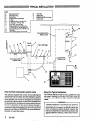
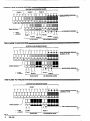
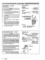
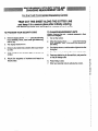
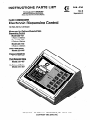
LIST
INSTRUCTIONS-PARTS
This manualcontains IMPORTANT
INSTRUCTIONSand WARNINGS.
READAND RETAINFOR REFERENCE.
FLUID COMMANDER
0
l
ORACO
-
Electronic Dispensing Control
120 VAC, 60 Hz, 0.25 Amps
Measured
in Gallons/Quarts/Pints
DisDensina
Model 223-731
1 Fluid td 12 Stations
Model 223-732
2 Fluids to 6 Stations
Model 223-733
3 Fluids to 4 Stations
Fluid Pulse Meter
Model 223-545
Pressure Relief Kit
Model 207-221
Fluid Solenoid Valve
Model 215-487
Air Solenoid Valve
Model 215-407
/
1
/
A
GRACO INC. P.O. BOX.1441 MINNEAPOLIS, MN 55440-1441
0COPYRIGHT 1990, GRACO INC.
308-036
Rev E
SupersedesD
TYPICAL INSTALLATION
KEY
Dispensing Control
Drain Sack Tube
Pump Intake Vaive
Supply Tank
Air Shutoff Valve. Bleed type
Air Filter
Air Solenoid Valve, P/N 215-407
Air Regulator, P/N 202-156
Pump
Pulse Meter. P/N 223-645
Pressure Relief IGI P/N 207-221,
l-1/2 npt (m x f).%U psi Max WPR
Fluid Shutoff Valve. P/N 108-458. 1R
T
V
tlsady Llghl
Dispense Vahre
ybeHo~
(3 to 8 It long)
FLUIDLINE
r---
FluidFilter
FluidSolenoidValve,PIN215-487
FLUIDSOLtNOlD
SIGNALLINE
1
r-L-l
I
M
How the Fluid Commander system works
About the -pica1
The operator programs the control unit by selecting the
appropriate fluid and station and then setting the quantity
to be dispensed. When the DISPENSEkey Is depressed
by the operator, the Control unit energlzes the respective
air and fluid solenoid valves. As the fluid is dispensed by
the service person, the pulse unit sends pulses to the control unit in proportion to the amount flowing through it.
When the number of pulses counted by the control unit is
equivalent to the preset quantity, the air and fluid solenoid
valves shut off. Refer to OPERATIONfor more detailed information on using the system.
The TYPICAL INSTALLATIONis only a guideline for a basic system, showing just one fluid. Your Grace sales representative can help you design a system to suit your
needs.
2
306-036
Installation
WARNING
A Pressure Relief Kit is required in your system to
reduce the risk of serious bodily Injury such as
splashing fluid in the eyes or on the skin, which can
occur if excessive system pressure ruptures the
lines and components. Install the kit as shown in the
Typical Installation Drawing. Order Grace apartNo.
207-221. See page 7.
INSTALLATION
ponents can withstand the pressures developed.
The maximum fluid working pressure of the Fluid
Commander System is 756 psi (52 bar). NEVER exceed the maximum working pressure of the lOWeSt
rated accessory (valve, pipe, fitting, hose, etc.) in
Mount the Fluid Commander
The Fluid Commander can be placed on a desktop or
mounted on a wall using the accessory wail bracket, pan
no. 186-472. See Fig 1.
WARNING
To reduce the risk of serious bodily Injury Including
electric shock, the Fluid Commander must be installed and wired by a qualified electrician, following all local, State and National codes.
Electrical wiring
Have a qualified electrician install and wire the system.
Use 16 AWG wire for the entire system, up to 360 feet. For
longer lengths, contact Grace Technical Assistance.
Fig 3 on page 4 shows where the wires connect at the rear
of the control, depending on the number of fluids you are
using.
Fig 2 shows how to make the electrical connections.
proti underthe lip of the terminal
strip and raisethe probe handleso
the top of the probe entersthe slot
and presses down the connector.
Installthe wire firmly and release
the probe.
CAUTION
To ensure correct polarity of the electrical supply,
use only GRACO power supply cord 11l-262. Any
other power supply cord may permanently damage
MAINTENANCE
Apply labels to control
After determining the fluids to be served by each control,
apply the appropriate labels within the raised area next to
the station pads. See Flg 4, page 5.
To clean the control
Spray mild household cleaner (only) on a soft cloth and
wipe the unit clean. Do not allowthe cleaner or any other
fluid to seep under the front panel.
This control Is not user-repairable. If it Is not working
properly, return It to your Grace distributor for repair. DO
NOT open the control or attempt to make any repairs
yourself.
WARNING
To reduce the risk of electric shock, turn off the control and disconnect the power supply cord from the
outlet before checking for loose or shorted wires,
and before servicing the meters, or solenoid valves.
306-636
3
THREE FLUIDS TO FOUR STATIONS
STATION FLUID SOLENOID VALVES
FLUID1
FLUID2
!
FLUID3
!
,
1
FLUID SOLENOID GROlJNDl
(postuons 13-16)
=
Station Numbers I
AIR SOLENOID GROUND1
=
+ = RED
- = BUCK
FLU’D 2
I
FLU’D 2
FLUID 3 ;
FLUID 3
AIR SOLENOID VALVES
PULSE UNITS
STATION FWID SOLENOID VALVES
I
I
FLUID 1
I
I
FLUID 2
FWID SOLENOID GROUND1
(posluons 13-M)
StaU~n Numbers
Y
J
AIR SOLENOID GROUND1
Y
+ = RED
- = SLACK
FLUID1
+
FLUID 2
i FLUID1
I
PULSE UNITS
FLUID2
AIR SOLENOID VALVES
STATION FLUID SOLENOID VALVES
r
I
FLUID 1
I
FWID SOLENOID GROUND1
@oswJnrr 13-16)
j
Xp
Y
AIR SOiENOlD GROUND&.
-
+ = RED
- = BLACK
4
306-036
;LUID 1
1
PULSE UNIT
; FLUID1
AIR SOLENOID VALVE
I
OPERATION
1. Program the security code and set the units
of measurement
5. To stop the dispense and check the Preset
amount
A four digit security code is required to activate the ContrOl
afler turning It on. Thls prevents unauthorized use of the
system.
Press STOP/CLEARand then press and hold AMOUNT
PRESETto verlfy the original order. Press DISPENSEto
continue the order.
me control is factory-set to dispense In quarts. Refer to
the instructions on the last page of this manual to change
the units of measurement, if necessary. Tear out the page
and keep it in a secure place.
6.
2.
Activate the control
Turn on the switch at rear of the control. The control does
a quick self-check and then the display shows fOUr
dashes. Enter your security code.
3.
Enter the order
Press the statlon number key for the appropriate fluid. The
light on the key will come on.
Press the white keys flrmly to enter the amount. For exam
ple;to enter 25.4 units, press the 10 twice, the 1 five times
and the 0.1 four times. If you make a mistake, press
STOP/CLEARand enter the total amount again.
NOTE: Holding in an amount key will cause the digit to
change continually until the key is released.
Press DISPENSE.The digital display shows all zeros and
the DISPENSElight blinks. As the order is dlspensed, the
display counts up and the fluid to the reel is shut off when
the preset amount is delivered.
4.
To checkthe preset amount during dispense
Press and hold AMOUNTPRESET.The order continues t0
be delivered unless you stop or clear It.
TO stop or clear an order
Press STOP/CLEARtwice to cancel and clear the order.
NOTE: This control delivers just one fluid to one station
at a time. During delivery, all pads on the control
are inac’tivated except AMOUNT PRESET and
STOP/CLEAR.
7.
TO find the total units delivered for each fluid
Press any station key for one fluid. Press and holdTOTAL
to read the amount. Repeat for the other fluids.
6.
If power is cut off
Each control has a built-in backup battery for its memory.
When power Is restored, reactivate the control by entering
the security code. The total amounts dispensed will still
be in the memory. If power was cut off during a dispense
cycle, the control will show the fluid, station and amount
already dispensed. Just press DISPENSEto continue.
The ON/OFF switch is also a 1.OAmp circuit breaker. If the
system shuts off unexpectedly, switch It off and on again.
If the problem continues, first determine if it is caused by
problems with the hard wiring. If the problem seems to be
with the control, return it to Grace for repair.
NOTE: Tnis control m
/
user repairable.
APPLYAPPROPRIATE
FLUIDIDENTIFICATION
L4BEL
RIGHTSTATION
KEY
Fig 4
KEYPAD FOR THREE FLUIDS TO FOUR STATIONS
308-036
5
ACCESSORIES
PULSE METER
TECHNICAL DATA
223-645
For Gallon/Quart Pint
E/ecfrksl
Input Voltage . . . . . . . . . . . .
Current Loop Output . . . .
CAUTION
To avoid damaging the electronic components of
the pulse meter control (1) :
1. Do not lay anything on the
eleCtrOniC
. 15 V Maximum
.4 milliamps OFF
10 milllamps ON
Hydraulk
Flow.. . . . . . . . . . . .
. 12gpm Maximum
(45.6 Lltedmin Maximum)
Max. Operating Pressure .
1566 psi (105 bar)
Inlet/Outlet.
.
. . . . . . . . . . l/2 npt
controt.
2. Be sure the open side of the electronic control
faces up if you lay it down.
.
3. Do not twist or force parts. Align parts properly
as instructed.
REPLACEMENT SCREWS ’
INCLUDED WITH ITEMS 1 AND 2
1. Shut off the power to the pump(s) and relieve
fluid pressure.
2.
TORQUE OPPOSITELY
AND EVENLY TO
lo-12IN-LB(1.2-1.4 N.m)
Remove the screws. Lift off the electronic
control.
3. Install a new metering unit (2) and/or electronic
control (1). Align the notches on the underside
of the electronic control with the cutaways in the
top of the meterlng unit. Use the new screws
and torque them oppositely and evenly to
lo-12 in-lb (1.2-l .4 N.m).
FLUID SOLENOID VALVE
PARTS LIST
1
2
215-487
ELECTRONICCONTROL
METERING UNtT
TECHNICAL DATA
Type . . . . . . . . .
. 2 way normally closed
Electrical Rating . . . . . . . . . . 26 V DC, 0.46 amp
NOTE: provides minimum current draw
when operated at 24 V DC
Coil Insulation . . . . . . . . .
Class H
Leads . . . . . . . . . . . . . . . . . . . 16AWGx16in.lona
Maximum Working Pressure.
3CCOpsi (207 ba5
Inlet/Outlet
...
.......
l/2 npt
Minimum Actuation Volts Required . . . . . . . . . . 20
Wirina Gauoe Reauired for
Lerigth of-Run .’. . . . . . . . . 16AWGupto300ft.
16AWGupto566ft.
14AWGuptolCGOft.
WARNING
electric shock, turn off the control and disconnect the power supply cord from the
outlet before checking for loose~or shorted wires,
and before servicing the meters, or solenoid
The solenoid valve is normally closed; foreign matter
could hold the valve open, preventing tt from stopping the fluid flow. If that happens, stop the,pump,
open the dispensing valve controlled by the solenoid
valve to relieve line pressure, and close the shutoff
valve ahead of the solenoid valve.
NUT
To clean the solenoid valve, unscrewthe nut, remove
the operator and unscrew the piston from the body.
Clean the pans and the seat In the body. Blow alr into
the body to clear the fluid passageways.
OPERATOR
Reassemble thevalveanddispensefluid tosee lfthe
held-open condition has been corrected. If It has
not, replace the solenoid valve.
BODY
NOTE: Dispense fluid at the dispensing valve controlled by the cleaned or replaced solenoid
valve until all air Is purged from the system.
6
223-655
222-661
308-036
IN
ACCESSORIES
AIR SOLENOID VALVE
215-407
TECHNICAL DATA
Type
3 way solenoid operated air valve,
normally closed
Electrical Rating . . . . . . . . . . . 24 V DC, 0.25 amps
General purpose, Class A
Coil Insulation . .
Encapsulated - Continuous Duty
Leads . . . . . . . . . . . . . . . . 16AWGx12.0ln.long
. . . . . . . Adapted to l/2 npt
Inlet/Outlet
Wiring Gauge Required for
LengthofRun . . . . . . . . . . 18AWGupto39Oft.
16AWGupto506ft.
14 AWG up to lOOOft.
\
W IRING HARNESS
224-090
50 ft (15.2 m) long. 16 AWG. 90 V, 2 wire
.
PRESSURE RELIEk KIT
207-221
300 psl(62 bar) MAXIMUM WORKING PRESSURE
Relieves fluid line pressure when It exceeds 900 psi
(62 bar).
PARTS LIST
1
:
102-527
167-453
TEE
RELiEF
pips
VALVE
l/2 npt(m)
3
4
156-849
205-l 69
NIPPLE, 3/8 npt
HOSE, nylon, 3/8”ID, cpld
5
157-350
ADAPTER, s/8 not(m) x
6
167-452
ADAPTER, hose, l-l/Z” npt(mxf) 1
3/E npsm (flYa); 3” (0.9 m) hQ
1/4npt(m)
1
1
308-036
7
TECHNICAL DATA
.... ..
. . . . . 750 psi (52 bar)
Fluid System Maximum Operating Pressure
Powerlnput . . . . . . . . . . . . . . . . . . . . . . . . . . . . . . . . . . . . . . . . . 110/12Ovolt,6OHz
Units of Measurement
Totalizlng .
.
Gallons to 19999
Dispensing . . . . . . . . . . . . . . 0.01 increments up to
199.99 Pints, Quarts, or Gallons
CircuitBreaker . . . . . . . . . . . . . . . . . . . . . . . . . . . . . . . . . . . . . . . . . . . . . . . . . l.OAmp
Power Supply Cord . . . . . . . . . . . . . . . . . . . . . . 7.5 ft (2.3 m), 18 AWG. 3 conductor,
molded vinyl plugs, 125 VAC, 10 amps
Control Module Power Output . . . . . . . . . . . 24 VDC hominal @ 750 mllliamps
maximum to any (1) fluid valve
and any (1) air valve simultaneously
Control Module Dimensions
Length . . . . . . . . . . . . . . . . . . . . . . . 8 in. (293 mm)
Width . . . . . . . . . . . . . . . . . . . . . . . 10 in. (245 mm)
Height. . . . . . . . . . . . . . . . . . .
4 In. (102 mm)
Weight .
..
......
4 lb (1.8 kg)
SERVICE INFORMATION
This manual has been updated to add wiring gauge re
qulred lengths to the Technlcal Data of the Air and Fluid
Solenoid valves.
8
308-036
308-036
9
THE GRACO WARRANTY AND DISCLAIMERS
WARRANTY
Gracowarrsnlsall equipment manufactured by it andbsarlng ilsnametobefrsefromdefscts in materialand workmanshi onlhedale
of sale by an authorized Grace distributor lo the original purchaser for use. As purchaser’s sole remedy for breach oft it is warranty,
Grace will, for a riod of twelve months from the dale of sale, repair or replace any part of the equipment proven defective. This warranty applies on p”
y when the equipment is InsfaIled. operated and malntained in accordance with Grace’s written recommendations.
This warranlydoesnotcover, and Gracoshall notbeliablsfor, anymalfunction,damaQeowearcaused byfaulty installation, mlsapplication, abrasion, corroslon. inadequate or improper maintenance, negligence, accident, tampering, or substitution of non-Grace
component parts. Nor shall Grace be liable for malfunction, damage or wear caused by the incompatibility with Grace equipment of
structures, accsssoriss, equipment or materials not supplied by Grew, orthe improperdesign, manufacture, installation, operation or
maintenance of structures, accessories, equipment or materials not supplied by Grace.
This warranty is conditioned upon the prepaid return of the equipment claimed to be defective to an authorized Grace distributor for
verification oflheclaim. lflheclaimed defect isverified. Gracowlll repairorreplacefres of Chargeany defective parts. heequipment
will beretumedtotheoriginal purchasertransportationprepaid. If inspsctionofthe equipmentdoes notdiscloseanydefect in material
or workmanship, repairs will bs made al a reasonablecharge, which charges may includethe costs of pans, labor andtranspxtatlon.
DISCLAIMERS AND LIMITATIONS
THE TERMS OF THIS WARRANTY CONSTlTUTE PURCHASERS SOLE AND EXCLUSIVE REMEDY AND ARE IN UEU OF ANY
OTHER WARRANTIES (EXPRESS OR IMPLIED), INCLUDING WARRANTY OF MERCHANTABIUTY OR WARRANTY OF FITNESS
FOR A PARTICULAR PURPOSE, AND OF ANY NON-CONTRACTUAL LIABILITIES, INCLUDING PRODUCT LIABILITIES, BASED
ON NEGUGENCE OR STRICT LIABILITY EVERY FORM OF LIABILITY FOR DIRECT, SPECIAL OR CONSEQUENTIAL DAMAGES
OR LOSS IS EXPRESSLY EXCLUDED AND DENIED. IN NO CASE SHALL GRACO’S LIABILITY EXCEED THE AMOUNT OF THE
PURCHASE PRICE. ANY ACTION FOR BREACH OF WARRANTY MUST BE BROUGHT WITHIN TWO (2) YEARS OFTHE DATE OF
SALE.
IMPORTANT PHONE NUMBERS
TOPLACEANORDER,
ContactyourGraco distributor, or call this numberto identlfy the distributor closest to you: I-800-328-021
1 Toll Free
FOR TEC/fN/CAL ASS/STANCE, service repair information or assistance regarding the application of Grace equipment:
l-800-543-0339
Toll Free
Subsidiary
Factory Branches: Atlanta, Chicago, Dallas, Detroit, Los Angeles, West Celdwell (N.J.)
and Affiliate Companies: Canada; England; Korea; Switzerland; France; Germany; Hong Kong; Japan
WACO INC. RO. BOX 1441 MINNEAPOLIS, MN 55440-1441
PRINTEDIN U.S.A. 308-036 3-90 Revised10-9,
10
308-036
303-036
11
PROGRAMMING SECURITY CODE AND
CHANGING MEASUREMENT UNITS
I
I
For the Fluid Commander Dispensina Control
I
TEAR OUT THIS SHEET ALONG THE DOTTED LINE
and keep it in a secure place after initiblly entering
the security code and setting the measurement units.
TO PROGRAMYOUR SECURITY CODE
TO CHANGE~MEASUREMENT
UNITS
1, Turn on the control.
(Gallon, Quart or Pint only - controls measured In IlterS
cannot be changed)
2. When the display shows - - - - press the following
keys: DISPENSE,TOTAL, most lower right station key,
and 0.1 key.
1. Turn on Me control.
3. The display shows PPPP.
2. When the display shows - - - - press the following
keys: DISPENSE,TOTAL, most lower right station key,
and TOTAL.
4. Enter any four station key numbers: this Is your SecUrity code.
3. The display shows LI and the station lights for the first
fluid glow.
5. Enter the same four numbers again lo activate the
control.
4. Press the 0.1 key lo change the measurement units.
6. Record the sequence of numbers and keep in a
secure place.
5. Press any station key for the next fluid, and press the
0.1 key to change units.
6.
Press TOTAL to end.
7. Enter your security code lo activate the control.
I
I
I
I
I
I
I
I
I
I
=e
.a_
6
@
_c
i
ii
I
I
I
I
I
I
I
I
I
I