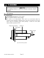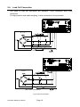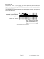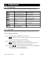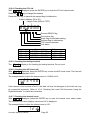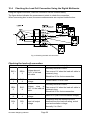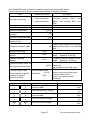
1
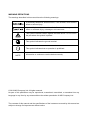
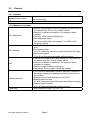
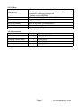
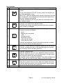
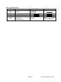
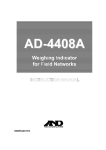
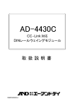
AD-4408C Weighing Indicator INSTRUCTION MANUAL 1WMPD4001849A WARNING DEFINITIONS The warnings described in this manual have the following meanings: A potentially hazardous situation which, if not avoided, could result in death or serious injury. A potentially hazardous situation which, if not avoided, may result in minor or moderate injury or damage to the instrument. This symbol indicates caution against electrical shock. Do not touch the part where the symbol is placed. This symbol indicates the ground terminal. This symbol indicates that an operation is prohibited. NOTE Information or cautions to use the device correctly. © 2012 A&D Company Ltd. All rights reserved. No part of this publication may be reproduced, transmitted, transcribed, or translated into any language in any form by any means without the written permission of A&D Company Ltd. The contents of this manual and the specifications of the instrument covered by this manual are subject to change for improvement without notice. Contents 1. Safety Precautions .......................................................................................................3 2. Introduction...................................................................................................................4 3. Specifications ...............................................................................................................5 3.1. Analog Section ....................................................................................................5 3.2. Digital Section .....................................................................................................5 3.3. General ...............................................................................................................6 4. Description of Each Part ...............................................................................................8 4.1. Front Panel .........................................................................................................8 4.2. Rear Panel ........................................................................................................10 5. Installation ..................................................................................................................12 5.1. Precautions .......................................................................................................12 5.2. Load Cell Cable Type........................................................................................13 5.3. Shield Connection .............................................................................................13 5.4. Load Cell Connection........................................................................................14 5.5. Checking the Load Cell Connection ..................................................................15 6. Operation....................................................................................................................16 6.1. General Function...............................................................................................16 6.2. Mode Map .........................................................................................................19 7. Calibration ..................................................................................................................20 7.1. General Description ..........................................................................................20 7.2. Calibration With an Actual Load (Cal5et).........................................................21 7.3. Calibration-Related Functions (Calf)................................................................23 7.4. Calibration Errors ..............................................................................................29 7.5. Load Cell Output Adjustment ............................................................................30 8. General Functions ......................................................................................................31 8.1. Setting Procedure .............................................................................................31 8.2. Adjusting the Digital Filter .................................................................................32 8.2. Basic Functions (fncf) .....................................................................................33 8.3. Standard Serial Output (Cl f) ..........................................................................34 8.4. CC-Link (CC f)..................................................................................................34 9. Interface......................................................................................................................35 9.1. Standard Serial Output......................................................................................35 9.2. CC-Link .............................................................................................................37 10. Maintenance ...............................................................................................................50 10.1. Error Messages...............................................................................................50 10.2. Check Mode ....................................................................................................50 10.3. Initialization Mode ...........................................................................................54 10.4. Checking the Load Cell Connection Using the Digital Multimeter ...................56 Page 1 AD-4408C Weighing Indicator 11. Setting List..................................................................................................................58 11.1. Basic Functions...............................................................................................58 11.2. Standard Serial Output....................................................................................59 11.3. CC-Link ...........................................................................................................59 11.4. Calibration-Related Functions .........................................................................60 12. External Dimensions...................................................................................................62 AD-4408C Weighing Indicator Page 2 1. Safety Precautions For safe and correct usage, read the following precautions carefully before using the indicator. Grounding Earth ground the indicator by connecting the ground terminal located on the rear panel to the earth, to prevent a fire, electrical shock or indicator malfunction. Do not share the ground line with other electrical power equipment. Appropriate power cable Use a power cable appropriate to the supply voltage and current used. Using an inappropriate cable may cause electrical leakage or a fire. Connect the power cable to the terminals firmly using compression lugs. Fuse replacement A fuse is provided to protect against a fire hazard. The indicator is equipped with various protection circuits and the fuse rarely burns out under normal operations. If the fuse burns out, the internal circuits may have been damaged by surges. Do not try to replace the fuse. Contact the nearest A&D dealer. Avoid water and moisture The indicator is not water-resistant. Securing the front panel to the control panel using the accessory panel mount packing will provide the indicator the IP-65 protection. Avoid an environment with flammable gases. Do not use the indicator in places where flammable gases are present. Indicator overheat To prevent the indicator from overheating, allow appropriate clearance between the peripheral devices. If the ambient temperature exceeds the specified operating temperature, use a fan to cool the environment. Page 3 AD-4408C Weighing Indicator 2. Introduction The AD-4408C is a weighing indicator that amplifies signals from a load cell, converts it to digital data and displays it as a mass value. The accessory panel mount packing will provide the indicator the IP-65 protection. This indicator has the following performance: Input sensitivity: ......................... 0.15 μV /d Display resolution: ..................... 999,999 d max. Sampling rate:............................ 100 times/second Input voltage range: ................... -35 mV to +35 mV (-7 mV/V to +7 mV/V) Digital span mode: Keying in the load cell output voltage (mV/V) allows calibration to be performed without an actual load. CC-Link interface: A CC-Link interface, provided as standard equipment, allows construction of a weighing system easily on a CC-Link network. NOTE: The AD-4408C CC-Link is a remote device station. By switching the number of occupied stations (for example 1, 2 or 4), up to 42 indicators can be connected to one master device when only AD-4408Cs are used. The unit, d indicates a minimum division. AD-4408C Weighing Indicator Page 4 3. Specifications 3.1. Analog Section Input sensitivity Input voltage range Zero adjustment range Load cell excitation voltage Load cell drive capacity Temperature Zero coefficient Span Non-Linearity A/D conversion method A/D resolution count Display resolution Sampling rate 3.2. 0.15 μV/d or greater -35 mV to +35 mV (-7 mV/V to +7 mV/V) -35 mV to +35 mV (-7 mV/V to +7 mV/V) 5VDC 5%, 120 mA with remote sensing capability Maximum 8 x 350 Ω load cells 0.02 μV /°C typ., 0.1 μV /°C max. 3ppm /°C typ., 15ppm /°C max. 0.005 % of full scale Delta-sigma method Approximately 16,000,000 counts 999,999 d max. 100 times/second Digital Section Display element Measurement display Status indicators Key switches • Measurement display: 6-digit 7-segment green LED • Character height: 14.6 mm • Polarity display: 1 green LED • Status indicator: 6 red LEDs • Switches between NET and GROSS • Selectable decimal places (101, 102, 103, 104, 105) • Overflow display All the digits turn OFF. (When the polarity is negative, the minus sign appears at the highest-order digit.) ZERO, STABLE, GROSS, NET, HOLD, ZERO, TARE, NET/GROSS, F, ON/OFF, ENTER, CAL Page 5 AD-4408C Weighing Indicator 3.3. General 3.3.1. Interface Standard serial output CC-Link interface Output for communication with A&D peripheral devices (20 mA current loop) CC-Link ver.1.10 remote device station 3.3.2. Measuring functions Zero adjustment Zero tracking Tare Stability detection Digital filter AD-4408C Weighing Indicator • Sets the gross weight to zero by pressing the ZERO key or a command from the CC-Link master station. • Selection of disable or enable for the operation when unstable. • The zero value is battery backed up. • Zero adjustable range Can be set optionally in the range of 1 to 100% of the weighing capacity. • Tracks the weight drift around the zero point to maintain zero. • Zero tracking time 0.0 to 5.0 seconds (Can be set optionally within the range.) • Zero tracking band 0.0 to 9.9 d (Can be set optionally within the range.) • Sets the net weight to zero by pressing the TARE key or a command from the CC-Link master station. • Selection of disable or enable for the operation when unstable or negative. • The tare weight is battery backed up. • Tare range: Gross weight ≤ Weighing capacity • Turns ON the stabilization indicator when the variables of the weight values per sampling are within the set band in the set time. • Stability can be confirmed using the CC-Link. • Stability detection time 0.0 to 9.9 seconds (Can be set optionally within the range.) • Stability detection band 0 to 9 d (Can be set optionally within the range.) Cutoff frequency range: 0.07 to 11 Hz Page 6 3.3.3. Other Power source Power consumption Operating temperature Operating humidity Installation method Mass • Zero value and tare weight Memory backup by lithium battery. (Approx. 10 years) • Calibration data and function data Written into the EEPROM 100 VAC to 240 VAC, +10%, -15%, (50/60 Hz) Approximately 10 VA -10°C to +40°C 85% R.H. or less (no condensation) Panel mount Approximately 800 g 3.3.4. Accessories Item CC-Link connector Connector operation lever Weighing capacity plate Unit label Panel mount packing Terminal block cover Quantity 1 1 1 1 1 1 Data backup Model name 1TM-721-105/037A 1TM-231-131 108-4023453 108-4023456 106-4004213 107-4005384 Page 7 AD-4408C Weighing Indicator 4. Description of Each Part 4.1. Front Panel Fig.1 Front panel Displays No. Name 1 Main display 2 ZERO 3 STABLE 4 5 GROSS NET 6 HOLD 7 8 UNIT 9 Capacity plate 10 CAL Description Displays the weight value, setting values, error messages, etc. Turns ON when the weight value is in the center of zero. • Turns ON when the weight value is stable. • The stability conditions can be changed in the calibration-related functions. Turns ON when the displayed value is a gross weight. Turns ON when the displayed value is a net weight. • Turns ON when the weight value is being held. • Two hold modes can be selected in the general functions, either normal hold or peak hold. The function for this indicator can be selected in the general functions, depending on the purpose. • Place a unit label. • A unit used for weighing is set in the calibration-related functions. Place a weighing capacity plate. • The key to enter the calibration mode. • The key is concealed by a sealable cover. To avoid unintentional operations, keep the cover attached except when entering the calibration mode. AD-4408C Weighing Indicator Page 8 Key switches No. Name ON/OFF ESC 11 12 ENTER Net/B/G NET GROSS 15 TARE 16 ZERO 17 Seal • The key to proceed to the selected mode. • Confirms the setting value and stores the data when pressed after a setting is changed. • The function for this key can be selected in the general functions, from the list below: None Manual print command Hold Alternate switch Momentary switch Clear the tare weight Clear the zero value • The key decreases the value of the blinking digit by one when the numerical values are being entered. 13 14 Description • The key to turn the indicator ON (Weighing mode) and OFF (OFF mode). • To turn the indicator OFF (OFF mode), press and hold the key for three seconds or more. • When OFF, all of the displays and external output/input devices are turned OFF, but a decimal point located at the right side of the main display remains ON. • The key functions as an ESC key when the numerical values are being entered. • The key to switch between the gross weight and the net weight. • The key increases the value of the blinking digit by one when the numerical values are being entered. • The key to perform tare. • The tare conditions are set in the calibration-related functions. • The key shifts the position of the blinking digit to the right when the numerical values are being entered. • In the OFF mode, pressing the ON/OFF key while holding down the TARE key will clear the zero value and the tare weight. • The key to zero the current display. • The zero conditions are set in the calibration-related functions. • The key shifts the position of the blinking digit to the left when the numerical values are being entered. • Can be sealed using a wire seal. Page 9 AD-4408C Weighing Indicator 4.2. Rear Panel 2 3 4 1 Fig.2 Rear panel No. 1 2 3 4 Name Terminal block CC-Link connector CC-Link status LEDs Testing terminal 1 Terminal block Terminal No. 1 EXC+ 2 SEN+ 3 SEN4 EXC5 SIG+ 6 SIG7 SHLD 8 C.L. 9 C.L. 10 F.G. 11 12 13 Description See the detailed description below. See the detailed description on the next page. Leave this terminal unconnected. Function Load cell excitation voltage (+) Sensing input (+) Sensing input (-) Load cell excitation voltage (-) Load cell input (+) Load cell input (-) Shield Standard serial output (Current loop) Standard serial output (Current loop) Frame ground Earth ground AC power source AC power source Load cell connection NOTE: Terminals 7 (SHLD) and 11 (E) are internally connected. To avoid unintentional operations, keep the cover attached on the terminal block. Screw size: M3, tightening torque: 0.5Nxm AD-4408C Weighing Indicator Page 10 3 CC-Link status LEDs LED RUN SD RD ERR ON Normal Transmitting Receiving • Setting error • CRC error • Station trouble OFF • Resetting • No signal Normal Blinking When a setting value is changed. . Page 11 AD-4408C Weighing Indicator 5. Installation The weighing indicator is a precision electronic instrument. Handle it carefully. 5.1. Precautions 5.1.1. Environment The operating temperature is -10°C to +40°C. Do not install the indicator in direct sunlight. The indictor is not water-resistant. When used in an environment where the indicator may be exposed to splashing water, secure the front panel to the control panel using the accessory panel mount packing. It makes the front panel water-resistant equivalent to IP-65. Panel mount packing Guide rail Control panel Washer Screw Fig.3 Panel mounting method AD-4408C Weighing Indicator Page 12 5.1.2. Power source Earth ground the indicator to prevent electrical shock or indicator malfunction. Before connecting the indicator to the power source, read the instruction manual thoroughly. Do not connect the indicator to the power source before the installation is complete. To avoid electrical shock, do not handle the power cable with a wet hand. Earth ground the indicator. Do not share the ground line with other electrical power equipment. The power requirement is 100 VAC to 240 VAC and the frequency is 50 Hz or 60 Hz. Use a stable power source free from instantaneous power failure or noise. To avoid a malfunction, do not share the power line with other devices. The output voltage of a load cell is a very sensitive signal. Keep all electrical noise sources away from the load cell and load cell cable. Use shielded I/O cables. Connect the cable shield to the F.G. terminal or the indicator housing. 5.2. Load Cell Cable Type Load cell cables should have high insulation and shielding performance. Use shielded cables with the insulator that is made of materials with high insulation resistance such as Teflon® and polyethylene. NOTE: Teflon is a registered trademark of DuPont. 5.3. Shield Connection Connect the load cell shield wire only to the shield terminal (terminal 7 of the terminal block located on the rear panel) of the AD-4408C. No ground is connected between the load cell and the AD-4408C. This is to prevent the ground loop generated by multiple ground points. Gound loop can be a major cause of noise and interference. Page 13 AD-4408C Weighing Indicator 5.4. Load Cell Connection Two types of load cell connection are available: 6-wire connection and 4-wire connection. For high precision and stable weighing, 6-wire connection is recommended. (A) 6-wire connection (B) 4-wire connection Fig.4 Load cell connection AD-4408C Weighing Indicator Page 14 Type Advantages The error is small even when the load cell cable is 6-wire connection extended, a thin load (recommended) cell cable is used, or multiple load cells are used. Disadvantages Use a 6-wire shielded cable Complicated wiring when a summing box is used. The influence of the load cell cable resistance worsens the temperature coefficient. Prone to the influence of the contact resistance of the connector 4-wire connection Simple wiring Description The error increases when the load cell cable is extended or multiple load cells are used. Precautions on performing the 4-wire connection Be sure to connect terminals 1 and 2 (EXC+ and SEN+) and terminals 3 and 4 (SEN- and EXC-). If the cable needs extending, use a cable with as large a cross-sectional area as possible or keep the cable as short as possible. 5.5. Checking the Load Cell Connection When the load cell connection is complete, follow the procedure below to check the connection. Step 1 Perform a visual check to ensure that the wiring is correct. Step 2 Turn the AD-4408C ON. All the digits may be OFF before calibration. Even under such a condition, the check mode can be used. Step 3 Enter the check mode and check the load cell output value. Refer to “10.2.1. Entering the check mode” to enter the A/D check mode. Step 4 Confirm that the displayed load cell output value matches the specified value. Normally the displayed value will be the load cell rated output value or less. Step 5 If an error occurs, refer to “10.4. Checking the Load Cell Connection Using the Digital Multimeter” to check the connection. Page 15 AD-4408C Weighing Indicator 6. Operation 6.1. General Function 6.1.1. Zero adjustment Zero adjustment is a function to set the gross weight to zero. It is performed by pressing the ZERO key or by a command from the CC-Link master station. The zero adjustment range is set in Calf05 (zero adjustment range) and is expressed in percent of the weighing capacity with the calibration zero point as the center. Zero adjustment is disabled, even within the zero adjustment range, when the A/D converter overflow occurs. A ZERO error is output if zero adjustment is not performed. The zero value is stored in the battery backup RAM and is maintained, even if the power is disconnected. Clearing the zero value is performed using the F key assigned to clear the zero value. Alternately, apply power to the indicator while holding down the TARE key, or with the indicator in the OFF mode, press and hold the TARE key and press the ON/OFF key, to clear the zero value. Functions related to zero adjustment z Calf05: Changes the zero adjustment range. (0 to 100%) z Calf10: Enables or disables zero adjustment when unstable. z Calf16: Enables or disables power-ON zero (function to zero upon power-ON). 6.1.2. Zero tracking Zero tracking is a function to track the weight drift around the zero point to maintain zero. The zero tracking time is set in Calf06 (zero tracking time) and the zero tracking band is set in Calf07 (zero tracking band). When the weight drift is within the specified ranges, zero tracking is performed automatically. A ZERO error is not output even if zero tracking is not performed. Functions related to zero tracking z Calf06: Changes the zero tracking time. (0.0 to 5.0 seconds) z Calf07: Changes the zero tracking band. (0.0 to 9.9 d) AD-4408C Weighing Indicator Page 16 6.1.3. Tare Tare is a function to store the gross weight as the tare value and set the net weight to zero. The tare weight is stored in the battery backup RAM and is maintained, even if the power is disconnected. Clearing the tare weight is performed using the F key assigned to clear the tare weight. Alternately, apply power to the indicator while holding down the TARE key, or with the indicator in the OFF mode, press and hold the TARE key and press the ON/OFF key, to clear the tare weight. Functions related to tare z Calf10: Enables or disables tare when unstable. z Calf11: Enables or disables tare when the gross weight is negative. 6.1.4. F key Assign a function to the F key in the general functions. Functions related to the F key zfncf02: Assigns a function to the F key from the functions below: 0: None 1: Manual print command 2: Hold 3: Alternate switch (Read the description below.) 4: Momentary switch (Read the description below.) 5: Clear the tare weight 6: Clear the zero value zCalf15: Enables or disables clearing the zero value. zCalf20: Enables or disables the print command when the gross weight is negative. Alternate switch and momentary switch zBy assigning these switches to the F key, the ON/OFF status of the F key can be transmitted to the CC-Link master station. This is useful when building a CC-Link network or performing maintenance. zIn the case that the station number is 1 and the number of occupied stations is 4, the ON/OFF status is transmitted to RX006F of the address map (In sync with display) . (ON: 1, OFF: 0) zThese switches perform as below: Alternate switch Press the switch once and release the switch to turn ON or OFF. Press the switch again to turn OFF or ON. Momentary switch Only when the switch is being pressed, the F key is ON. When released, OFF. Page 17 AD-4408C Weighing Indicator 6.1.5. display Assign a function to the display in the general functions. Functions related to the display zfncf04: Assigns a function to the display from the functions below: 0: None 1: Zero tracking in progress 2: Alarm (Zero range setting error, over, low battery) 3: F key status (Read the description below.) F key status zEnables when alternate switch or momentary switch is selected for fncf02. The display turns ON when the F key is ON and turns OFF when the F key is OFF. 6.1.6. Memory backup The indicator has two kinds of memory. EEPROM Memory used to store important data, without power supplied, that the occurrence of re-writing is seldom. Data example: Calibration data, Function data Battery backup RAM Memory backup Data Calibration data Function data Zero value Tare weight AD-4408C Weighing Indicator Memory used to store temporary data that the occurrence of re-writing is often. Data example: Zero value, Tare weight Method Description EEPROM Maintained regardless of battery condition. Battery backup RAM The life of the battery is approximately 10 years at 25°C with the power disconnected. Page 18 6.2. Mode Map The indicator has several modes to perform various operations. Perform mode switching by key operation as shown below, only in the direction of the solid arrow. After setting a mode, the indicator resets automatically. Alternately, the indicator resets, when the power is disconnected. Automatic reset after setting Power ON Weighing mode Switch using the ON/OFF key See the note below. OFF mode NOTE: When the power is disconnected with OFF mode, the indicator starts with OFF mode upon power-ON again. General function mode Enter using the key combination ENTER + F Initialization mode Maintenance mode Enter using the key combinations ENTER + F and then ZERO + ENTER Calibration mode Check mode Calibration using an actual load Calibration-related function mode Enter using the CAL key All data initialization mode Fig.5 Mode map Page 19 AD-4408C Weighing Indicator 7. Calibration 7.1. General Description In the calibration mode, the operation to relate the output voltage from a load cell to the mass value and other operations directly related to weighing are performed. Calibration with an actual load Calibration-related function Digital span All data initialization Calibration is performed using a calibration weight. • Zero calibration: Adjusts the indicator so that the measured value will be zero when no load is applied to the load cell. • Span calibration: Enter the calibration weight value and place the calibration weight on the load cell. When the indicator enters the mode of calibration with an actual load, the tare weight and the zero value will be automatically cleared. Setting basic constant values of the indicator such as the minimum division and weighing capacity and other data directly related to weighing is performed. Setting the parameters for digital span calibration is also performed. Calibration is performed without an actual load, by keying in the load cell output voltage (mV/V). • Input voltage at zero: Key in the load cell output at zero. • Input voltage at span: Key in the load cell output at span. (Load cell output at full capacity – load cell output at zero) • Calibration weight value at span: Key in the calibration weight value corresponding to the input voltage at span. (The input voltage at span is related to the mass value.) Clears all the data in the EEPROM and battery backup RAM. NOTE: All the data set in the calibration mode is stored in the EEPROM and is maintained regardless of battery condition. AD-4408C Weighing Indicator Page 20 7.2. Calibration With an Actual Load (Cal5et) Calibration is performed using a calibration weight Before performing calibration for the first time, set the unit, decimal point position, minimum division and weighing capacity in the calibration-related function mode. NOTE: To avoid drift caused by changes in temperature, warm up the indicator for ten minutes or more before performing calibration with an actual load. Step 1 Press the ON/OFF key to turn the indicator ON (weighing mode) if it is in the OFF mode. Remove the CAL key cover and press the CAL key. CalL is displayed to indicate that the indicator enters the calibration mode. Step 2 Press the ENTER key to display Cal5et . The indicator enters the mode of calibration with an actual load. To return to the weighing mode, press the ESC key. Zero calibration Step 3 Press the ENTER key to display Cal 0 . If zero calibration is not to be performed, press the F key and go to step 5. To monitor the current weight value, press the CAL key. Press the CAL key again to display CalL 0 . Step 4 With nothing placed on the load cell, wait for the stabilization indicator to turn ON and press the ENTER key. - - - - - - is displayed for approximately two seconds. Span calibration Step 5 Press the ENTER key when Cal5pn is displayed. The calibration weight value (the weighing capacity currently set) is displayed and the least digit of the value blinks. < > ∧ ∨ keys: Press to correct the value to the value of the calibration weight used. CAL key : Press to monitor the current value (the gross weight) and press again to display the calibration weight value. ESC key : Press three times to return to the weighing mode without performing span calibration. Step 6 Place a calibration weight on the load cell. Wait for the stabilization indicator to turn ON and press the ENTER key. - - - - - - is displayed for approximately two seconds. Step 7 Calend is displayed. To re-adjust the span, press the F key. Page 21 AD-4408C Weighing Indicator Step 8 Press the ESC key. Cal5et is displayed and the calibration data is written into the EEPROM. The current state is the same as that of step 2. To return to the weighing mode, press the ESC key again. NOTE: If C errX is displayed, an error has occurred. Refer to “7.4. Calibration Errors” to take some measures. If the decimal point blinks, it indicates that the current value is not the weight value. AD-4408C Weighing Indicator Page 22 7.3. Calibration-Related Functions (Calf) Step 1 Press the ON/OFF key to turn the indicator ON (weighing mode) if it is in the OFF mode. Remove the CAL key cover and press the CAL key. Cal is displayed to indicate that the indicator enters the calibration mode. Step 2 Press the ENTER key to display Cal5et . The indicator enters the mode of calibration with an actual load. To return to the weighing mode, press the ESC key. Step 3 Press the ∧ or ∨ key to select CalfF and press the ENTER key. Step 4 Press the ∧ or ∨ key to select a function number to be used and press the ENTER key. The current setting value is displayed. Step 5 Change the value as necessary. Two methods to change are available, depending on the function number as below Method Description Only the available parameter is displayed and blinks. Selecting a parameter Press the ∧ or ∨ key to select a parameter. All the digits are displayed and a digit to be changed blinks. Inputting the value Press the < or > key to select a digit and press the ∧ or ∨ key to change the value. After setting, press the ENTER key. The next function number is displayed. When the value is not to be changed, press the ESC key to return to the function number display. Step 6 Press the ESC key. Cal5et is displayed and the data of the calibration-related functions is written into the EEPROM. The current state is the same as that of step 2. To return to the weighing mode, press the ESC key again. NOTE: If a value exceeding the settable range is entered, err dt is displayed and the input is canceled. If the decimal point blinks, it indicates that the current value is not the weight value. Page 23 AD-4408C Weighing Indicator Function No. Parameter or Setting range Function Calf01 0 to 3 Unit Calf02 0 to 5 Decimal point position Calf03 1 to 6 Minimum division Calf04 Weighing 1 to 999999 capacity Calf05 0 to 100 Description Unit of the weight value 0: None 1: g 2: kg 3: t 4: lb (USA version) Decimal point position of the weight value 0: None 123456 12345.6 1: 101 2: 102 1234.56 3 3: 10 123.456 4: 104 12.3456 5 5: 10 1.23456 Minimum division (d) of the weight value 1: 1 2: 2 3: 5 4: 10 5: 20 6: 50 Weighing capacity of the weighing instrument Weighing is possible up to the value of this setting plus 8 d. If the value exceeds this, overflow will occur and will not be displayed. The decimal point position is the same as the setting of Calf02. Range to enable zero adjustment by the ZERO key or a command from the CC-Link master station. Expressed in percent of the weighing capacity with the calibration zero point as Zero the center, when performing power-ON adjustment zero, with the initial zero point as the range center. For example, if this is set to 2, the value in the range of ±2% of the weighing capacity with the calibration zero point at the center will set to zero. AD-4408C Weighing Indicator Page 24 Default value 2 0 1 20000 2 Function No. Parameter or Setting range Calf06 0.0 to 5.0 Calf07 0.0 to 9.9 Function Default value Description Zero tracking time Performs zero tracking using this setting in combination with the setting of the zero tracking band. When 0.0, zero tracking will not be performed. Zero tracking band Unit: second in 0.1 increments Performs zero tracking using this setting in combination with the setting of the zero tracking time. When 0.0, zero tracking will not be performed. 0.0 0.0 Unit: d (minimum division) in 0.1 increments Page 25 AD-4408C Weighing Indicator Function No. Parameter or Setting range Calf08 0.0 to 9.9 Calf09 0 to 9 Function Default value Description Stability detection time Performs stability detection using this setting in combination with the setting of the stability detection band. When 0.0, stability detection will not be performed. (Stable all the time) Stability detection band Unit: second in 0.1 increments Performs stability detection using this setting in combination with the setting of the stability detection time. When 0, stability detection will not be performed. (Stable all the time) 1.0 2 Unit: d (minimum division) Stability detection outputs the STABLE signal when changes in the weight value are within a certain range during a certain time. Weight value CALF09 CALF08 CALF09 CALF08 STABLE signal Calf10 0 to 1 Calf11 0 to 1 Calf12 0 to 1 Tare and zero adjustment when unstable Tare when the gross weight is negative Output when overflow and unstable AD-4408C Weighing Indicator Tare and zero adjustment when the weight value is unstable. 0: Disables both functions. 1: Enables both functions. 1 Tare when the gross weight is negative. 0: Disables tare. 1: Enables tare. 1 Standard serial output if the weight value overflows and is unstable. 0: Disables output. 1: Enables output. 1 Page 26 Function No. Parameter or Setting range Calf13 1 to 3 Calf14 1 to 2 Calf15 0 to 1 Calf16 0 to 1 Calf17 -7.00000 to 7.00000 Calf18 0.00001 to 9.99999 Calf19 1 to 999999 Function Description Condition to judge over when the gross weight is negative. Over at A/D negative over or negative 1: Gross weight < -999999 gross weight 2: Gross weight < negative weighing capacity 3: Gross weight < -19 d Condition to judge over when the net Over at weight is negative. negative net Gross weight negative over or weight 1: Net weight < -999999 2: Net weight < negative weighing capacity Select whether or not to clear the zero Clear the zero value. value 0: Disables. 1: Enables. Select whether or not to perform zero Zero upon upon power-ON. power-ON 0: Disables. 1: Enables. Input voltage from a load cell at zero. Input voltage at zero Default value 1 1 1 0 Unit: mV/V In zero calibration during the calibration 0.00000 with an actual load, this value is determined. Input voltage from a load cell at span Unit: mV/V Input voltage In span calibration during the calibration 2.00000 at span with an actual load, this value and the value of Calf19 are determined. The calibration weight value corresponding Calibration to the Input voltage at span of Calf18. weight value corresponding When performing digital span, Calf17, 20000 to Input 18 and 19 are required. voltage at The decimal point position is the same as span the setting of Calf02. Page 27 AD-4408C Weighing Indicator Input voltage CALF18 CALF17 CALF19 0 Displayed weight 0 NOTE: Record the setting values of Calf17, 18 and 19 in the “Setting List” at the end of the manual to prepare against a failure. By changing the parameters of Calf17, 18 and 19, “zero calibration” and “span calibration” can be adjusted optionally. (Digital span accuracy approx. 1/5000: The accuracy varies depending on the load cell output accuracy and the conditions of calibration.) Except for an emergency, perform calibration with an actual load. Calf20 0 to 1 Output when the gross weight is negative Calf21 0 to 1 Communication restriction Calf22 1 to 2 Header 2 AD-4408C Weighing Indicator Output by the manual print command when the gross weight is negative. 0: Enables output. 1: Disables output. Restriction on network-related communication such as changing station numbers or ID numbers and outputting by auto printing 0: Disables restriction. 1: Enables restriction. Second header for serial output 1: GS / NT / TR 2: G_ / N_ / T_ (_ space) Page 28 0 0 1 7.4. Calibration Errors When an error occurs during calibration, the error number is displayed. If calibration is finished without releasing the error, the setting values will be restored to the state before calibration. Calibration errors and remedies Error No. Description C err1 C err2 C err3 C err4 C err5 C err6 C err8 C err7 Remedy Make the minimum division greater or make the The display resolution (weighing weighing capacity smaller. capacity / minimum division) exceeds The specified value the specified value. depends on the instrument or specifications. Check the load cell rating and connection. Voltage at zero calibration exceeds in When nothing is wrong with the positive direction. the rating and connection, adjust the load cell output as described in the next section. Voltage at zero calibration exceeds in When the load cell or A/D converter may be the cause the negative direction. of error, confirm it by using the check mode. The value of the calibration weight Use an appropriate exceeds the weighing capacity. calibration weight and The value of the calibration weight is calibrate again. less than the minimum division. Use a load cell with higher The load cell sensitivity is not sufficient. sensitivity or make the minimum division greater. The load cell output voltage is too high Use a load cell with a when the load of the weighing capacity greater rating or make the is placed. weighing capacity smaller. Voltage at span calibration is less than Check the load cell voltage at the zero point. connection. Page 29 AD-4408C Weighing Indicator 7.5. Load Cell Output Adjustment Add a resistor as shown below to adjust the load cell output. Use a resistor with a high resistance value and a low temperature coefficient. SIG- "C Err 3" When exceeding in the negative direction) EXC+ EXC+ r to is es d R dde a R e a d si s de tor d "C Err 2" (When exceeding in the positive direction) SIG+ SIG- EXC- SIG+ EXC- Fig.6 Load cell output adjustment NOTE: As the zero adjustment range of the AD-4408C is wide, output adjustment is rarely required for the normal load cell. Before adjusting the load cell output, check the load cell (deformation, clearance around the load cell, incorrect wiring and load cell type) and load cell connection. AD-4408C Weighing Indicator Page 30 8. General Functions General functions are divided into groups per function and are indicated by the group name with the function number. NOTE: General functions determine the AD-4408C performance and all the data are stored in the EEPROM. 8.1. Setting Procedure Step 1 While holding down the ENTER key, press the F key. fnc is displayed to indicate that the indicator will enter the general function mode. Step 2 Press the ENTER key. The indicator enters the general function mode. To return to the weighing mode without entering the general function mode, press the ESC key. Step 3 Press the ∧ or ∨ key to select the function group to be set. Display Group name Basic function fncf Standard serial output Cl f CC-Link CC f Press the ENTER key. The function number will be displayed. Step 4 Press the ∧ or ∨ key to select the function number to be set. Press the ENTER key. The current setting value will be displayed. Step 5 Change the setting value using either one of the methods below. Method Description Only the available parameter is displayed and blinks. Selecting a parameter Press the ∧ or ∨ key to select a parameter. All the digits are displayed and a digit to be changed blinks. Inputting the value Press the < or > key to select a digit and press the ∧ or ∨ key to change the value. After setting, press the ENTER key. The next function number is displayed. When the parameter is not to be changed, press the ESC key to return to the function number display. Page 31 AD-4408C Weighing Indicator Step 6 Press the ESC key. The function number disappears and the indicator returns to the state of step 2. Press the ESC key to store the setting values in the EEPROM and return to the weighing mode. NOTE: If a value exceeding the settable range is entered, err dt is displayed and the input is canceled. If the decimal point blinks, it indicates that the current value is not the weight value. 8.2. Adjusting the Digital Filter Adjust the digital filter using fncf05 (Digital filter) and fncf06 (Frequency divider ratio). Method 1 While fncf06 is fixed to 1 (divider ratio 1), adjust fncf05. Cutoff frequency: 11.0 Hz to 0.7 Hz Method 2 If Method 1 does not work, perform as follows: While fncf05 is fixed to 8 (1.0 Hz), adjust fncf06. Cutoff frequency: 0.5 Hz to 0.1 Hz Digital filter cutoff frequency = fncf05 cutoff frequency fncf06 divider ratio High cutoff frequency Low cutoff frequency High response speed ⇔ Low response speed Prone to external disturbance Less prone to external disturbance AD-4408C Weighing Indicator Page 32 8.2. Basic Functions (fncf) Function No. Parameter or Setting range Ffncf01 000000 to 111111 Function Disable key switch Default value Description Each digit of the setting corresponds to a key switch. Only available in the weighing mode. 0: Does not disable the key switch function. 1: Disables the key switch function. Key assignment 6th 5th 4th ZERO TARE Net/B/G NET GROSS 3rd 2nd 1st ON/OFF ESC ENTER Assigns a function to the F key. 0: None 1: Manual print command 2: Hold 3: Alternate switch 4: Momentary switch 5: Clear the tare weight 6: Clear the zero value NOTE: Clearing the zero value can be enabled or disabled by Calf15 1: 20 times/second 2: 10 times/second 3: 5 times/second Assigns a function to the display. 0: None 1: Zero tracking in progress 2: Alarm (Zero range setting error, over, low battery) 3: F key status Selects a cutoff frequency. 0: None 1: 11.0 Hz 2: 8.0 Hz 3: 5.6 Hz 4: 4.0 Hz 5: 2.8 Hz 6: 2.0 Hz 7: 1.4 Hz 8: 1.0 Hz 9: 0.7 Hz fncf02 0 to 6 F key fncf03 1 to 3 Display update rate fncf04 0 to 3 display fncf05 0 to 9 Digital filter fncf06 1 to 10 Frequency Divides digital filter cutoff frequency by the divider setting. ratio 1: Normal hold Hold 2: Peak hold fncf07 1 to 2 Page 33 000000 (binary) 0 1 0 8 1 1 AD-4408C Weighing Indicator 8.3. Standard Serial Output (Cl f) Function No. Parameter or Setting range Function Cl f01 1 to 5 Output data Cl f02 1 to 3 Data transfer mode Cl f03 1 to 2 Baud rate Description 1: Displayed weight 2: Gross weight 3: Net weight 4: Tare weight 5: Gross/Net/Tare 1: Stream 2: Auto printing (See the NOTE below) 3: Manual printing 1: 600 bps 2: 2400 bps Default value 1 1 2 NOTE: When “1: Enables restriction” is selected for Calf21 (Communication restriction), auto printing will not be performed even if auto printing conditions are met. 8.4. CC-Link (CC f) Function No. Parameter or Setting range Function CC f01 1 to 64 Station number CC f02 0 to 2 Occupied stations CC f03 0 to 4 Baud rate CC f04 0 to 1 Initialization CC f05 0 to 2 Output data AD-4408C Weighing Indicator Description n: Station number 0: One 1: Two 2: Four 0: 156 kbps 1: 625 kbps 2: 2.5 Mbps 3: 5 Mbps 4: 10 Mbps 0: Not required (When the AD-4408C is turned on and the CC-Link is ready, the remote READY flag (RX007B) becomes active without performing initialization.) 1: Required (When the AD-4408C is turned on and the CC-Link is ready, the remote READY flag (RX007B) becomes active after the initialization is complete.) 0: Displayed weight 1: Net weight 2: Gross weight Specify what data to output when the number of occupied stations is 1 or 2. Page 34 Default value 1 2 4 1 0 9. Interface 9.1. Standard Serial Output The standard serial output with 0 to 20 mA can be connected to a device such as an A&D printer or remote display. The interface has no power source. Therefore, the external devices to be connected must have a power source. The setting values of the standard serial output are changed in the general functions Cl f01 to Cl f03. Type Data bits Start bit Parity Stop bit Baud rate Code 0 to 20 mA current loop 7 bits 1 bit 1 bit, even 1 bit 600, 2400 bps ASCII 9.1.1. Connection Standard serial output Standard serial output Internal circuit Frame ground 8 9 C.LOOP output terminal 10 No polarity C.L. F.G. Fig.7 Standard serial output pin connection Fig.8 Standard serial output internal circuit NOTE: The standard serial output connection has no polarity. When a shielded cable is used, connect the shield to the F.G. terminal. Page 35 AD-4408C Weighing Indicator 9.1.2. Output data The data format used is A&D standard format. This is a format to be used with an A&D printer or remote display and consists of two headers, data, unit and a terminator. A&D standard format Header 1 Header 2 Separator Data (ASCII code) Unit (five types) ASCII code ST US OL GS NT TR , 0 to 9 + SP (space) . SP SP SP g kg SP t lb Hexadecimal [53 54] [55 53] [4F 4C] [47 53] [4E 54] [54 52] [2C] [30 to 39] [2B] [2D] [20] [2E] [20 20] [20 67] [6B 67] [20 74] [6C 62] Description Stable Unstable Overload Gross weight Net weight Tare weight No unit g kg t lb (USA version) A&D standard format examples Gross weight Net weight Tare weight Data with a decimal point Positive overflow Negative overflow Unstable data “Output OFF” data NOTE: The decimal point position is the same even when overflow occurs. AD-4408C Weighing Indicator Page 36 9.1.3. Data transfer mode Three data transfer modes are available; stream, auto printing and manual printing. Stream mode Auto printing mode Manual printing mode 9.2. Transmits data in sync with the display update rate. If the indicator can not catch up with the update rate because of the baud rate, the transmission is paused until the next updating. The transmitted data is the same as what is being displayed. Data that is not displayed is never transmitted. Transmits data once only when the weight value with 5 d or greater is stable. For another transmission, the weight value must fall below 5 d once. Transmits data when the F key that is assigned to Manual print command is pressed or a command is sent from the CC-Link master station. CC-Link The AD-4408C CC-Link is a remote device station of CC-Link ver.1.10. When a CC-Link is used, the AD-4408C can be controlled by the PLC remote I/O or remote registers. So, the program can be simple. And connection to a PLC is simple, thus, a weighing system can be built easily. The setting values of CC-Link are changed in the general functions CC f01 to CC f04. Station number Number of occupied stations Baud rate Initialization 1 to 64 1 station, 2 stations, 4 stations 156 kbps, 625 kbps, 2.5 Mbps, 5 Mbps, 10 Mbps Not required or required Communications connector The connector used can be attached or removed while the power is ON. The function of each signal line is as follows. DA DB DG SLD FG Signal DA Signal DB Signal ground Shield Frame ground Page 37 AD-4408C Weighing Indicator Status LEDs LED RUN SD RD ERR ON Normal Transmitting Receiving • Setting error • CRC error • Station trouble OFF • Resetting • No signal Normal Fig.9 CC-Link connector and LEDs AD-4408C Weighing Indicator Page 38 Blinking When the setting values are changed 9.2.1. Address map Remote register (Number of occupied stations: 4) Addresses are examples when the station number is set to 1. AD-4408C --> Master station Master station --> AD-4408C Remote Buffer Remote Buffer Station Name Name register memory register memory RWr0000 2E0 RWw0000 1E0 Net weight RWr0001 2E1 RWw0001 1E1 1 RWr0002 2E2 RWw0002 1E2 Gross weight RWr0003 2E3 RWw0003 1E3 RWr0004 2E4 Reserved RWw0004 1E4 internally RWr0005 2E5 RWw0005 1E5 Reserved 2 internally RWr0006 2E6 Error code RWw0006 1E6 RWr0007 2E7 Error sub-code RWw0007 1E7 RWr0008 2E8 RWw0008 1E8 Reserved RWr0009 2E9 RWw0009 1E9 3 internally RWr000A 2EA RWw000A 1EA RWr000B 2EB RWw000B 1EB RWr000C 2EC RWw000C 1EC Command Command data data response RWw000D RWr000D 2ED 1ED 4 RWr000E 2EE Command No. response RWw000E 1EE Command No. RWr000F 2EF Reserved internally RWw000F 1EF Reserved internally Remote register (Number of occupied stations: 2) Addresses are examples when the station number is set to 1. AD-4408C --> Master station Master station --> AD-4408C Remote Buffer Remote Buffer Name Name Station register memory register memory RWr0000 2E0 1E0 Displayed value RWw0000 (Net / Gross) RWw0001 Reserved RWr0001 2E1 1E1 1 internally RWr0002 2E2 Error code RWw0002 1E2 RWr0003 2E3 Error sub-code RWw0003 1E3 RWr0004 2E4 Command RWw0004 1E4 Command data data response RWw0005 RWr0005 2E5 1E5 2 RWr0006 2E6 Command No. response RWw0006 1E6 Command No. RWr0007 2E7 Reserved internally RWw0007 1E7 Reserved internally Remote register (Number of occupied stations: 1) Addresses are examples when the station number is set to 1. AD-4408C --> Master station Master station --> AD-4408C Remote Buffer Remote Buffer Station Name Name register memory register memory RWr0000 2E0 Displayed value RWw0000 1E0 (Net / Gross) RWw0001 RWr0001 2E1 1E1 Reserved 1 internally RWr0002 2E2 Error code RWw0002 1E2 RWr0003 2E3 Error sub-code RWw0003 1E3 Page 39 AD-4408C Weighing Indicator Numeric values of the remote register All the values are hexadecimal. Negative values are expressed by the two’s complement. Decimal Hexadecimal (16 bits) Hexadecimal (24 bits) Hexadecimal (32 bits) -10 FFF6 FFFFF6 FFFFFFF6 -1 FFFF FFFFFF FFFFFFFF 0 0000 000000 00000000 1 0001 000001 00000001 10 000A 00000A 0000000A NOTE: Writing is prohibited in the internally reserved areas. Writing in the remote output (RY) and the remote register (RWw) of the internally reserved areas may cause the indicator to malfunction. Values of the remote input (RX) and the remote register (RWr) of the internally reserved areas are not fixed. Error code Error code 0 1 2 3 4 5 Error status flag (Indicator error) No error AD error (Module error) EEPROM error (Writing error) RAM error (Writing error) Calibration error (Calibration value error) Display error (Mode error) AD-4408C Weighing Indicator Page 40 Remote I/O (Number of occupied stations: 4) Addresses are examples when the station number is set to 1. AD-4408C --> Master station Master station --> AD-4408C Remote Buffer Remote Buffer Station Name Name input memory output memory RX0000 RY0000 Reserved Reserved internally internally RX0001 RY0001 Command processing Command processing RX0002 RY0002 response request RX0003 Read/write response RY0003 Read/write request RX0004 Reserved RY0004 internally RX0005 RY0005 CPU normal RX0006 RY0006 operation 0E0 160 RX0007 Reserved internally RY0007 RX0008 RY0008 Decimal 20 Reserved 1 3-bit point 2 RX0009 RY0009 binary internally position 22 RX000A RY000A RX000B RY000B RX000C RY000C RX000D RY000D RX000E RY000E 1 RX000F RY000F Reserved RX0010 RY0010 Zero internally RX0011 RY0011 Clear zero RX0012 RY0012 Tare RX0013 RY0013 Clear tare RX0014 RY0014 Hold RX0015 RY0015 Net display RX0016 RY0016 Gross display RX0017 Stable RY0017 Print command 0E1 161 RX0018 Reserved internally RY0018 RX0019 Capacity exceeded RY0019 RX001A Hold in progress RY001A RX001B RY001B Reserved RX001C RY001C Reserved internally RX001D RY001D internally RX001E RY001E RX001F Weighing failure RY001F RX0020 2 0E2 RX0020 162 | | | Reserved internally | | RX005F 3 0E5 RX005F 165 Page 41 AD-4408C Weighing Indicator AD-4408C --> Master station Master station --> AD-4408C Remote Buffer Remote Buffer Station Name Name input memory output memory RX0060 Net over RY0060 RX0061 Net under RY0061 RX0062 Gross over RY0062 RX0063 Gross under RY0063 RX0064 A/D over RY0064 RX0065 A/D under RY0065 Net in the RX0066 RY0066 center of zero Gross in the RX0067 0E6 RY0067 166 center of zero RX0068 Net display RY0068 RX0069 Gross display RY0069 RX006A Tare in progress RY006A Reserved RX006B Low battery RY006B internally RX006C Zero error RY006C RX006D Tare error RY006D RX006E Net display error RY006E RX006F In sync with RY006F 4 RX0070 RY0070 RX0071 RY0071 RX0072 RY0072 RX0073 Reserved RY0013 internally RX0074 RY0074 RX0075 RY0075 RX0076 RY0076 RX0077 RY0077 Request flag of Reply flag of RX0078 RY0078 0E7 167 initialization initialization Reply flag of initial Request flag of initial RX0079 RY0079 data setting data setting Request flag of RX007A Error status flag RY007A error reset RX007B Remote READY flag RY007B RX007C RY007C Reserved RX007D Reserved RY007D internally internally RX007E RY007E RX007F RY007F AD-4408C Weighing Indicator Page 42 Remote I/O (Number of occupied stations: 2) Addresses are examples when the station number is set to 1. AD-4408C --> Master station Master station --> AD-4408C Remote Buffer Remote Buffer Station Name Name input memory output memory RX0000 RY0000 Reserved Reserved internally internally RX0001 RY0001 Command processing Command processing RX0002 RY0002 response request RX0003 Read/write response RY0003 Read/write request RX0004 Reserved RY0004 internally RX0005 RY0005 CPU normal RX0006 RY0006 operation 0E0 160 RX0007 Reserved internally RY0007 RX0008 RY0008 Decimal 20 Reserved 1 3-bit point 2 RX0009 RY0009 binary internally position 22 RX000A RY000A RX000B RY000B RX000C RY000C RX000D RY000D RX000E RY000E 1 RX000F RY000F Reserved RX0010 RY0010 Zero internally RX0011 RY0011 Clear zero RX0012 RY0012 Tare RX0013 RY0013 Clear tare RX0014 RY0014 Hold RX0015 RY0015 Net display RX0016 RY0016 Gross display RX0017 Stable RY0017 Print command 0E1 161 RX0018 Reserved internally RY0018 RX0019 Capacity exceeded RY0019 RX001A Hold in progress RY001A Reserved RX001B RY001B internally Reserved RX001C RY001C internally RX001D RY001D RX001E RY001E RX001F Weighing failure RY001F Page 43 AD-4408C Weighing Indicator AD-4408C --> Master station Remote Buffer Station Name input memory RX0020 Net over RX0021 Net under RX0022 Gross over RX0023 Gross under RX0024 A/D over RX0025 A/D under Net in the RX0026 center of zero Gross in the RX0027 0E2 center of zero RX0028 Net display RX0029 Gross display RX002A Tare in progress RX002B Low battery RX002C Zero error RX002D Tare error RX002E Net error RX002F In sync with 2 RX0030 RX0031 RX0032 RX0033 Reserved internally RX0034 RX0035 RX0036 RX0037 Request flag of RX0038 0E3 initialization Reply flag of initial RX0039 data setting RX003A RX003B RX003C RX003D RX003E RX003F AD-4408C Weighing Indicator Error status flag Master station --> AD-4408C Remote Buffer Name output memory RY0020 RY0021 RY0022 RY0023 RY0024 RY0025 RY0026 RY0027 RY0028 RY0029 RY002A RY002B RY002C RY002D RY002E RY002F RY0030 RY0031 RY0032 RY0033 RY0034 RY0035 RY0036 RY0037 RY0038 RY0039 RY003A Remote READY flag RY003B RY003C Reserved RY003D internally RY003E RY003F Page 44 162 Reserved internally 163 Reply flag of initialization Request flag of initial data setting Request flag of error reset Reserved internally Remote I/O (Number of occupied stations: 1) Addresses are examples when the station number is set to 1. AD-4408C --> Master station Master station --> AD-4408C Remote Buffer Remote Buffer Station Name Name input memory output memory RX0000 RY0000 Zero RX0001 RY0001 Clear zero RX0002 RY0002 Tare Reserved RX0003 RY0003 Clear tare internally RX0004 RY0004 Hold RX0005 RY0005 Net display RX0006 RY0006 Gross display RX0007 Stable RY0007 Print command 0E0 160 RX0008 Reserved internally RY0008 RX0009 capacity exceeded RY0009 RX000A Hold in progress RY000A RX000B RY000B Reserved RX000C RY000C internally RX000D RY000D RX000E RY000E Reserved RX000F Weighing failure RY000F internally RX0010 RY0010 1 RX0011 RY0011 RX0012 RY0012 RX0013 Reserved RY0013 internally RX0014 RY0014 RX0015 RY0015 RX0016 RY0016 RX0017 RY0017 Request flag of Reply flag of RX0018 RY0018 0E1 161 initialization initialization Reply flag of initial Request flag of initial RX0019 RY0019 data setting data setting Request flag of RX001A Error status flag RY001A error reset RX001B Remote READY flag RY001B RX001C RY001C Reserved RX001D Reserved RY001D internally internally RX001E RY001E RX001F RY001F Weighing failure Net over Gross over A/D over Low battery Tare error Net under Gross under A/D under Zero error Net display error Page 45 AD-4408C Weighing Indicator 9.2.2. Commands The write command is used to send a command to the AD-4408C from the master station. For details, refer to “Write command” in “9.2.3. Timing chart”. Command No. 0 0 0 0 0 0 0 0 Command data 1 2 3 4 5 6 7 8 Command Zero Clear zero Tare Clear tare Hold Net display Gross display Print command 9.2.3. Timing chart Below examples are when the station number is set to 1 and the number of occupied stations is set to 4. When the AD-4408 is turned on When the AD-4408C is turned on and the CC-Link is ready, the request flag of initialization (RX0078) becomes active. The master station confirms that RX0078 is active, performs initialization and turns the reply flag of initialization (RY0078) ON. The AD-4408C turns the request flag of initialization (RX0078) OFF and turns the remote READY flag (RX007B) ON. Turn OFF the reply flag of initialization (RY0078) in the master station. NOTE: When CC f04 of the CC-Link functions is set to 0 (Initialization not required), the remote READY flag (RX007B) becomes active without performing initialization. When the request flag of initialization (RX0078) is ON, the reply flag of initialization (RY0078) is turned ON. Power ON Request flag of initialization (RX0078) Reply flag of initialization (RY0078) Remote READY flag (RX007B) Fig.10 Performance upon power-ON AD-4408C Weighing Indicator Page 46 When the request flag of initialization (RX0078) is OFF, the reply flag of initialization (RY0078) is turned OFF. Resuming from suspended modes When the AD-4408C is in a mode that suspends weighing, such as calibration or OFF mode, the remote READY flag (RX007B) becomes inactive because a correct weight value can not be output. To resume from this condition, take the same steps as described in “When the AD-4408C is turned on” above. Requesting initialization from the master station When requesting the initial data setting to the AD-4408C from the master station, turn the request flag of initial data setting (RY0079) ON while the remote READY flag (RX007B) is active. The AD-4408C turns the remote READY flag (RX007B) OFF and performs initial data settings. When initial data settings are complete, the reply flag of initial data setting (RX0079) is turned ON. Turn OFF the request flag of initial data setting (RY0079) in the master station. When the remote READY flag (RX007B) is ON, the request flag of initial data setting (RY0079) is turned ON. When the reply flag of initial data setting (RX0079) is ON, the request flag of initial data setting (RY0079) is turned OFF. Request flag of initial data setting (RY0079) Remote READY flag (RX007B) Reply flag of initial data setting (RX0079) When the reply flag of initial data setting (RX0079) is OFF, the remote READY flag (RX007B) is turned ON again. Fig.11 Performance of request flag of initial data setting Page 47 AD-4408C Weighing Indicator Write command Specify the data type to write by the command No. (RWw000E). Place the data to write in the command data (RWw000C to RWw000D). The read/write request (RY0003) is OFF. Read/write request (RY0003) Command No. (RWw000E) Command data (RWw000C to 000D) Command processing request (RY0002) Read/write response (RX0003) Command No. response (RWr000E) Command processing response (RX0002) Fig.12 Performance of the write command CPU normal operation The CPU normal operation (RX0006) is a signal to check that the AD-4408C is turned on and it functions normally. During normal operation, the signal is reversed at an interval of 0.5 to 1 second. CPU normal operation (RX0006) 0.5 to 1 second Fig.13 CPU normal operation signal AD-4408C Weighing Indicator Page 48 Error status flag When an error occurs to the AD-4408C, the remote READY flag (RX007B) becomes inactive and the error status flag (RX007A) becomes active to inform the master station of the error occurrence. The master station requests to reset the error status flag, by activating the request flag of error reset (RY007A). Error status flag (RX007A) Request of error reset (RY007A) Errorflagreset request (RY007 Remote READY flag (RX007B) Error code (RWr0006) Error sub-code (RWr0007) Error code (RWr0006) and Error sub-code (RWr0007) will be cleared to 0. Fig.14 Resetting the error status flag Page 49 AD-4408C Weighing Indicator 10. Maintenance 10.1. Error Messages If an error message is displayed, refer to the chart below to take proper measures. Error message ad err ra err eeperr Calerr lb err C errX err dt 10.2. Cause Remedy Data can not be acquired Repair is required. from the A/D converter. Data can not be written into Repair is required. the battery backup memory. Perform initialization. Correct data can not be If initialization does not clear the read from the EEPROM. error, repair is required. Calibration data is not Perform calibration. correct. No battery backup. The Perform zero adjustment or clear zero and tare values are the zero value. And then, update cleared. the zero value. Calibration error Refer to “7.4. Calibration Errors”. The setting value is out of Check the setting value and set the settable range. again. Check Mode The check mode checks the performance of the display, key switches and external I/O. 10.2.1. Entering the check mode Step 1 While holding down the ENTER key, press the F key. fnc is displayed to indicate that the indicator will enter the general function mode. To return to the weighing mode, press the ESC key. Step 2 While holding down the ZERO key, press the ENTER key. 1Chc is displayed to indicate that the indicator will enter the check mode. Press the ENTER key again to display an item to be checked. Step 3 Press the ∧ or ∨ key to select the item to be checked and press the ENTER key to enter the check mode of the selected item. To exit from the current mode, press the ESC key. AD-4408C Weighing Indicator Page 50 Display Chckey Chc Cl Chc CC Chc r5 Chc ad Chc in Chcpr9 C5 pr9 C5 eep Item to be checked Key switches Standard serial output CC-Link Testing terminal A/D (Load cell) Internal count Program version Program checksum Memory (EEPROM) checksum 10.2.2. Checking the key switches With Chckey displayed, press the ENTER key to enter the key switch check mode. In the key switch check mode, six squares ( ) are displayed. Each square corresponds to a key switch as shown below. When a key switch is pressed, the corresponding square moves up ( ). When the CAL key is pressed, the minus LED turns ON. To exit from the key switch check mode, press the ESC key twice. CAL ZERO TARE Net/B/G NET GROSS ON/OFF ESC ENTER 10.2.3. Checking the standard serial output With Chc ClL displayed, each time the ENTER key is pressed, the test data is transmitted with the baud rate set in the general functions and the decimal point blinks. Test data S T , G S , + 0 0 0 0 0 . 0 k g Page 51 CR LF 0.0 AD-4408C Weighing Indicator 10.2.4. Checking the CC-Link With Chc CC displayed, press the ENTER key to enter the CC-Link check mode. Press the ∧ or ∨ key to change the address. Press the CAL key to transmit the request flag of initialization. 2 digits: Address (00 to 3F) 4 digits: Data (0000 to FFFF) 88.8888 Remote READY flag Error status flag Reply flag of initial data setting Request flag of initialization CPU normal operation Link status Address 05 to 0C 0D to 1C 25 to 2C 2D to 3C Remote I/O RY0000 to RY007F RWw0000 to RWw000F RX0000 to RX007F RWr0000 to RWr000F Buffer memory 160 to 167 1E0 to 1EF 0E0 to 0E7 2E0 to 2EF 10.2.5. Checking the testing terminal The Chc r5 display is for checking the testing terminal. Do not use it. 10.2.6. Checking the A/D (load cell) With Chc ad displayed, press the ENTER key to enter the A/D check mode. The load cell output value is displayed in mV/V. The example below is when the internal count is 1.23456 mV/V. 1.23456 If the internal count exceeds ±7mV/V, the load cell may be damaged or the load cell may be connected incorrectly. Refer to “10.4. Checking the Load Cell Connection Using the Digital Multimeter” to check the connection. 10.2.7. Checking the internal count With Chc in displayed, press the ENTER key to enter the internal count check mode. The internal count value (display value times 10) is displayed. The example below is when the internal count is 123. 123. AD-4408C Weighing Indicator Page 52 10.2.8. Checking the program version With Chcpr9 displayed, press the ENTER key to display the version of the current program. The example below is when the program version is 1.00. p001.00 10.2.9. Checking the program checksum With C5 pr9 displayed, press the ENTER key to display the program checksum. The example below is when the checksum is EF. C500ef 10.2.10. Checking the EEPROM checksum With C5 eepEP displayed, press the ENTER key to display the EEPROM checksum. The memory set in the general functions is not counted. The example below is when the checksum is EF. C500ef 10.2.12. Checking the calibration-related functions About the settings of the calibration-related functions, refer to “7.3. Calibration-Related Functions”. Page 53 AD-4408C Weighing Indicator 10.3. Initialization Mode The initialization restores the contents of the battery backup RAM and EEPROM to the default values. The three types of initialization are available as shown below. Initialization mode Display RAM initialization ini ra General functions initialization inifnc All data initialization iniall Description Initializes the contents of the battery backup RAM only. As the zero and tare values are stored in the battery backup RAM, they will be restored to 0. Initializes the contents of the general functions stored in the battery backup RAM and EEPROM. Initializes all the contents in the battery backup RAM and EEPROM. The calibration-related data is also initialized. So, calibration is required before using the indicator again. 10.3.1. RAM initialization / General functions initialization Step 1 While holding down the ENTER key, press the F key. fnc is displayed to indicate that the indicator will enter the general function mode. To return to the weighing mode, press the ESC key. Step 2 While holding down the ZERO key, press the ENTER key. 1Chc is displayed to indicate that the indicator will enter the check mode. Step 3 Press the ∧ or ∨ key to select the initialization mode ( ini ) and press the ENTER key. Step 4 Press the ∧ or ∨ key to select the item to be initialized and press the ENTER key. Step 5 All the status LEDs blink to prompt a confirmation. To initialize, hold down the ENTER key for three seconds or more. After initialization, the indicator is reset and all the display segments are ON. And the indicator enters the weighing mode. To exit from this mode without performing initialization, press the ESC key. AD-4408C Weighing Indicator Page 54 10.3.2. All data initialization Step 1 Remove the cover concealing the CAL key and press the CAL key. Cal is displayed to indicate that the indicator enters the calibration mode. Step 2 Press the ENTER key to display Cal5et . The indicator enters the mode of calibration with an actual load. To return to the weighing mode, press the ESC key. Step 3 Press the ∧ or ∨ key to select the all data initialization mode ( iniallLL ) and press the ENTER key. Step 4 All the status LEDs blink to prompt a confirmation. To initialize, hold down the ENTER key for three seconds or more. After initialization, the indicator is reset and all the display segments are ON. And the indicator enters the weighing mode. To exit from this mode without performing initialization, press the ESC key. Page 55 AD-4408C Weighing Indicator 10.4. Checking the Load Cell Connection Using the Digital Multimeter Using the digital multimeter, load cell connection can be checked easily. The figure below indicates the measurement points to check the connection. When a summing box is used, the same measurements are required inside the box. Fig.15 Checking the load cell connection Checking the load cell connection Measurement point EXC+ 1 EXC+ 1 SEN+ 2 What to measure How to judge Normally less than 100mV. Voltage drop at EXC+ of the load cell cable Can exceed 1V when the load cell cable is extremely long. Should be 0V for 4-wire connection. EXC4 Load cell excitation voltage SEN3 EXC4 Normally less than 100mV. Voltage drop at Can exceed 1V when the load cell cable is EXC- of the load cell extremely long. cable Should be 0V for 4-wire connection. SIG6 EXC4 Load cell voltage SIG+ 5 SIG6 median Load cell output voltage Correct value: 4.75 to 5.25V About 2.5V (half of the excitation voltage) Compared with the theoretical value obtained from the load cell rating, actual load and excitation voltage. Normally 0 to 15mV. AD-4408C Weighing Indicator Page 56 If the AD-4408C does not function properly, contact the nearest A&D dealer. Use the chart below to write necessary items before contacting the dealer. Item Record your value Description For 4-wire connection, a jumper is □ 4-wire connection required between EXC+ and Load cell connection SEN+, and between EXC- and □ 6-wire connection SIG-. Load cell type Load cell rating [Unit ] Load cell rated output [mV/V] Load cell maximum safe [%] overload Number of load cells used [pcs] Summing box (status of use) Cable length between the indicator Length of extension cable [m] and the device such as a summing box Indicator initial load [Unit ] Indicator minimum In case of decimal number, all the [Unit ] division digits Example: 0.002 kg Indicator weighing In case of decimal number, all the [Unit ] capacity digits Example: 10.000 kg -0.1mV/V to load cell rated Load cell output value at [mV/V] sensitivity the initial load (at no load) (depending on the initial load) When loaded to capacity, the Load cell output value Load cell output value output value at the initial load + [mV/V] when loaded to capacity at the load load cell rated output (or when a mass of [Unit ] (within the maximum safe choice is loaded) overload) Measurement point EXC+ SEN+ 1 2 EXC+ EXC1 4 SENEXC3 4 SIGEXC6 4 SIG+ SIG5 6 What to measure Voltage drop at EXC+ of the load cell cable Load cell excitation voltage Voltage drop at EXC- of the load cell cable Load cell median voltage Load cell output voltage Page 57 Result [mV] [V] [mV] [V] [mV] AD-4408C Weighing Indicator 11. Setting List When performing maintenance, use the following list as a memo. In case of inquiry about the product, inform of the user setting. 11.1. Basic Functions Function No. Parameter or Setting range Ffncf01 000000 to 111111 fncf02 0 to 6 fncf03 1 to 3 fncf04 0 to 3 fncf05 0 to 9 Description Default value Disable key switch 000000 0: Does not disable the key switch function. (binary) 1: Disables the key switch function. Assigns a function to the F key. 0: None 1: Manual print command 2: Hold 0 3: Alternate switch 4: Momentary switch 5: Clear the tare weight 6: Clear the zero value Display update rate 1: 20 times/second 1 2: 10 times/second 3: 5 times/second Assigns a function to the display. 0: None 1: Zero tracking in progress 0 2: Alarm (Zero range setting error, over, low battery) 3: F key status Digital filter (cutoff frequency) 0: None 1: 11.0 Hz 2: 8.0 Hz 3: 5.6 Hz 4: 4.0 Hz 8 5: 2.8 Hz 6: 2.0 Hz 7: 1.4 Hz 8: 1.0 Hz 9: 0.7 Hz fncf06 1 to 10 Frequency divider ratio 1 fncf07 1 to 2 Hold 1: Normal hold 2: Peak hold 1 AD-4408C Weighing Indicator Page 58 User setting 11.2. Standard Serial Output Function No. Parameter or Setting range Cl f01 1 to 5 Cl f02 1 to 3 Cl f03 1 to 2 11.3. Description Output data 1: Displayed weight 2: Gross weight 3: Net weight 4: Tare weight 5: Gross/Net/Tare Data transfer mode 1: Stream 2: Auto printing 3: Manual printing Baud rate 1: 600 bps 2: 2400 bps Default value User setting 1 1 2 CC-Link Function No. Parameter or Setting range CC f01 1 to 64 CC f02 0 to 2 CC f03 0 to 4 CC f04 0 to 1 CC f05 0 to 2 Description Station number n: Station number Number of occupied stations 0: One 1: Two 2: Four Baud rate 0: 156 kbps 1: 625 kbps 2: 2.5 Mbps 3: 5 Mbps 4: 10 Mbps Initialization 0: Not required 1: Required Output data 0: Displayed weight 1: Net weight 2: Gross weight Page 59 Default value User setting 1 2 4 1 0 AD-4408C Weighing Indicator 11.4. Calibration-Related Functions Function No. Parameter or Setting range Description Default value Calf01 0 to 3 Unit of the weight value 0: None 1: g 2: kg 3: t 4: lb (USA version) 2 Calf02 0 to 5 Decimal point position of the weight value: 10n 0 Calf03 1 to 6 Calf04 1 to 999999 Calf05 0 to 100 Calf06 0.0 to 5.0 Calf07 0.0 to 9.9 Calf08 0.0 to 9.9 Calf09 0 to 9 Calf10 0 to 1 Calf11 0 to 1 Calf12 0 to 1 Minimum division (d) of the weight value 1: 1 2: 2 3: 5 4: 10 5: 20 6: 50 Weighing capacity of the weighing instrument 1 The decimal point position is the same as the setting of Calf02. Range to enable zero adjustment by the ZERO key or a command from the CC-Link master station. Expressed in percent of the weighing capacity with the calibration zero point as the center Zero tracking time (Unit: second) When 0.0, zero tracking will not be performed. 20000 Zero tracking band (Unit: 0.1 d) When 0.0, zero tracking will not be performed. Stability detection time (Unit: second) When 0.0, stability detection will not be performed. Stability detection band (Unit: d) When 0, stability detection will not be performed. Tare and zero adjustment when the weight value is unstable. 0: Disables both functions. 1: Enables both functions. Tare when the gross weight is negative. 0: Disables tare. 1: Enables tare. Standard serial output if the weight value overflows and is unstable. 0: Disables output. 1: Enables output. 0.0 AD-4408C Weighing Indicator Page 60 2 0.0 1.0 2 1 1 1 User setting Function No. Parameter or Setting range Calf13 1 to 3 Calf14 1 to 2 Calf15 0 to 1 Calf16 0 to 1 Calf17 -7.00000 to 7.00000 Calf18 0.00001 to 9.99999 Calf19 1 to 999999 Calf20 0 to 1 Calf21 0 to 1 Calf22 1 to 2 Description Condition to judge over when the gross weight is negative. A/D negative over or 1: Gross weight < -999999 2: Gross weight < negative weighing capacity 3: Gross weight < -19 d Condition to judge over when the net weight is negative. A/D negative over or 1: Net weight < -999999 2: Net weight < negative weighing capacity Select whether or not to clear the zero value. 0: Disables. 1: Enables. Select whether or not to perform zero upon power-ON. 0: Disables. 1: Enables. Input voltage from a load cell at zero. X.XXXXX mV/V Input voltage from a load cell at span X.XXXXX mV/V The value of the calibration weight corresponding to the span input voltage Select whether or not to output when the gross weight is negative. 0: Enables output. 1: Disables output. Select whether or not to restrict network-related communication. 0: Disables restriction. 1: Enables restriction. Second header for serial output 1: GS / NT / TR 2: G_ / N_ / T_ (_ space) Page 61 Default value User setting 1 1 1 0 0.00000 2.00000 20000 0 0 1 AD-4408C Weighing Indicator 12. External Dimensions Unit: mm Fig.16 External dimensions AD-4408C Weighing Indicator Page 62 MEMO Page 63 AD-4408C Weighing Indicator MEMO AD-4408C Weighing Indicator Page 64 3-23-14 Higashi-Ikebukuro, Toshima-ku, Tokyo 170-0013 Telephone: [81] (3) 5391-6132 Fax: [81] (3) 5391-6148 JAPAN A&D ENGINEERING, INC. 1756 Automation Parkway, San Jose, California 95131 U.S.A. Telephone: [1] (408) 263-5333 Fax: [1] (408)263-0119 A&D INSTRUMENTS LIMITED <UK Office> Unit 24/26 Blacklands Way, Abingdon Business Park, Abingdon, Oxfordshire OX14 1DY United Kingdom Telephone: [44] (1235) 550420 Fax: [44] (1235) 550485 A&D INSTRUMENTS LIMITED <German Sales Office> Große Straße 13 b 22926 Ahrensburg Deutschland Telefon: [49] (0) 4102 459230 Telefax: [49] (0) 4102 459231 A&D Australasia Pty Ltd. 32 Dew Street, Thebarton, South Australia 5031 AUSTRALIA Telephone: [61] (8) 8301-8100 Fax: [61] (8) 8352-7409 A&D KOREA Limited 한국에이.엔.디(주) 대한민국 서울시 영등포구 여의도동 36-2 맨하탄 빌딩 8층 ( 8th Floor, Manhattan Bldg. 36-2 Yoido-dong, Youngdeungpo-ku, Seoul, KOREA ) 전화: [82] (2) 780-4101 팩스: [82] (2) 782-4280 A&D RUS CO., LTD. Компания ЭЙ энд ДИ РУС 121357, Российская Федерация, г.Москва, ул. Верейская, дом 17 ( Bldg. 17, Vereyskaya st., Moscow, 121357 RUSSIAN FEDERATION ) тел.: [7] (495) 937-33-44 факс: [7] (495) 937-55-66 A&D Instruments India Private Limited ( 509, Udyog Vihar, Phase- , Gurgaon - 122 016, Haryana, India ) : 91-124-4715555 : 91-124-4715599