1
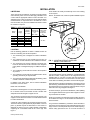
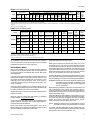
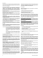
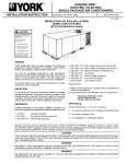
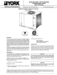
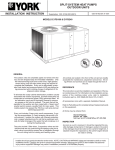
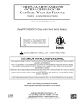
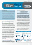
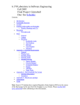
® INSTALLATION INSTRUCTION AIR COOLED SPLIT-SYSTEM AIR CONDITIONERS 550.13-N3Y (897) Supersedes: 550.13-N3Y (692) 035-14873 MODELS H2CA300 & 360 Style D Renewal Parts: GENERAL These units are designed for outdoor installation on a roof or at ground level. Every unit is completely packaged, piped and wired at the factory. Each unit is dehydrated, evacuated, leak tested and pressure tested at 450 psig before being pressurized with a holding charge of refrigerant-22. All controls are located in the front of the unit and are readily accessible for maintenance, adjustment and service. All wiring (power and control) can be made through the bottom of the unit. • Refer to Parts Manual for complete listing of replacement parts on this equipment. The above forms and all other forms referenced in this instruction may be ordered from: Publications Distribution Center Unitary Products Group P.O. Box 1592, York, Pa. 17405 INSPECTION REFERENCE This instruction covers the installation and operation of the basic condensing unit and interconnecting refrigerant mains. For information on the installation of the matching evaporator blower unit, refer to the following instruction: Model LEU360 - Form 550.13-N8 As soon as a unit is received, it should be inspected for possible damage during transit. If damage is evident, the extent of the damage should be noted on the carrier’s freight bill. A separate request for inspection by the carrier’s agent should be made in writing. See Form 50.15-NM for additional information. CAUTION Additional information on the design, installation, operation and service of this equipment is available in the following reference forms. THIS PRODUCT MUST BE INSTALLED IN STRICT COMPLIANCE WITH THE ENCLOSED INSTALLATION INSTRUCTIONS AND ANY APPLICABLE LOCAL, STATE, AND NATIONAL CODES INCLUDING, BUT NOT LIMITED TO, BUILDING, ELECTRICAL, AND MECHANICAL CODES. • • • • INCORRECT INSTALLATION, ADJUSTMENT, ALTERATION, SERVICE OR MAINTENANCE CAN CAUSE INJURY OR PROPERTY DAMAGE. REFER TO THIS MANUAL.FOR ASSISTANCE OR ADDITIONAL INFORMATION, CONSULT A QUALIFIED INSTALLER OR SERVICE AGENCY. 55.70-N1 55.70-N2 55.70-N3 55.05-NM - General Installation - Pre-start & Post-start Check List - General Service Information - Evacuation and Charging WARNING Installer should pay particular attention to the words: NOTE, CAUTION and WARNING. Notes are intended to clarify or make the installation easier. Cautions are given to prevent equipment damage. Warnings are given to alert installer that personal injury and/or equipment damage may result if installation procedure is not handled properly. 550.13-N3Y TABLE OF CONTENTS General ................................................................................ 1 Reference ............................................................................ 1 Inspection............................................................................. 1 Nomenclature....................................................................... 2 Operation .....................................................................11 Condenser Fan Motor Control ........................................... 12 Secure Owner’s Approval .................................................. 12 Maintenance ...................................................................... 12 Cleaning Condenser Surface ..................................... 12 Lubrication .................................................................. 12 Compressor Replacement.......................................... 12 INSTALLATION Limitations............................................................................ 3 Location ............................................................................... 3 Roof-Top Locations....................................................... 3 Ground Level Locations ............................................... 3 Clearances........................................................................... 4 Rigging ................................................................................. 4 Installing Support Legs ........................................................ 4 Compressor Hold-Down Nuts .............................................. 4 Discharge Line Hold-Down Bracket..................................... 4 Power Wiring........................................................................ 4 Control Wiring ...................................................................... 4 Compressor Crankcase Heaters .................................. 4 Refrigerant Mains................................................................. 5 Line Sizing .................................................................... 6 Evacuating and Charging ............................................. 6 Unit Dimensions................................................................. 10 TABLES No. Description Page 1 Application Data.......................................... 3 2 Minimum Clearances .................................. 4 3 Physical Data.............................................. 5 4 Electrical Data............................................. 5 5 Suction Lines .............................................. 8 6 Liquid Lines................................................. 9 7 Refrigerant Line Charge ............................. 9 FIGURES No. Description 1 OPERATION Sequence of Operation.......................................................11 Operation with 2-Stage Thermostat ............................11 Application with Blower Unit ........................................11 Compressor Motor Protection System................................11 Page Location of Bolt Holes and Weight Distribution.................................. 3 2 Typical Rigging ........................................... 4 3 Field Wiring - Model HCA300 ..................... 7 4 Field Wiring - Model HCA360 ..................... 7 PRODUCT NOMENCLATURE H 2 C A 3 0 0 A 2 5 PRODUCT CATEGORY VOLTAGE CODE H = Split-System Condensing Unit 25 = 208/230-3-60 46 = 460-3-60 58 = 575-3-60 PRODUCT GENERATION 2 = 2nd Generation NOMINAL COOLING CAPACITY PRODUCT IDENTIFIER CA = Condensing Section 2 300 = 25 Tons 360 = 30 Tons FACTORY INSTALLED HEAT A = Not Applicable Unitary Products Group 550.13-N3Y INSTALLATION LIMITATIONS These units must be installed in accordance with all national and local safety codes. If no local codes apply, installation must conform with the appropriate national codes. See Table 1 for Application Data. Units are designed to meet National Safety Code Standards. If components are to be added to a unit to meet local codes, they are to be installed at the dealer’s and/or the customer’s expense. These beams can usually be set directly on the roof. Flashing is not required. NOTE: On bonded roofs, check for special installation requirements. TABLE 1 - APPLICATION DATA Model H2CA 300A25 300A46 300A58 360A25 360A46 360A58 Saturation Ambient Air Suction Temp. Voltage on Condenser of Gas at Power Variation Compressor Supply (°F) Min. / Max. (°F) Min. / Max. Min. / Max. 208/230-3-60 187 / 252 460-3-60 432 / 504 575-3-60 540 / 630 0 / 115 32 / 53.5 208/230-3-60 187 / 252 460-3-60 432 / 504 575-3-60 540 / 630 1-3/8 1-3/8 3/4 3/4 LOCATION 4 2-1/2 5 Use the following guidelines to select a suitable location for both the condensing unit and the evaporator. (4) 11/16 HOLES EACH LEG (TYP.) 1. The condensing unit is designed for outdoor installation only. 2. The condenser fans are the propeller type and are not suitable for use with ductwork in the condenser air stream. 3. The condensing unit and the evaporator should be positioned to minimize the number of bends in the refrigerant piping. Refer to "Refrigerant Piping" for additional information. 4. The condensing unit should be as close to the evaporator as practical. 5. The condensing unit should not be installed where normal operating sounds may be objectionable. 6. The evaporator should be located within the building, either outside or inside the conditioned space. In addition to the above steps, refer to General Installation Instructions, Form 55.70-N1. ROOF-TOP LOCATIONS Be careful not to damage the roof. Consult the building contractor or architect if the roof is bonded. Choose a location with adequate structural strength to support the unit. The condensing unit must be mounted on level supports. The supports can be channel iron beams or wooden beams treated to reduce deterioration. A minimum of two (2) beams are required to support each unit. The beams should: (1) Be positioned perpendicular to the roof joists. (2) Extend beyond the dimensions of the section to distribute the load on the roof. (3) Be capable of adequately supporting the concentrated loads at the corner legs. See Figure 1. Unitary Products Group FIG. 1 - LOCATION OF BOLT HOLES AND WEIGHT DISTRIBUTION Leg (Lbs.) Unit HCA300 HCA360 A B C D 450 480 420 440 290 350 290 310 Operating Weight (Lbs.) 1450 1580 GROUND LEVEL LOCATIONS It is important that the units be installed on a substantial base that will not settle, causing strain on the refrigerant lines and possible leaks. A one-piece concrete slab with footers that extend below the frost line is recommended. The slab should not be tied to the building foundation as noises will telegraph. Ground level units can also be supported by concrete piers. These piers should (1) extend below the frost line, (2) be located under each of the section’s four corner legs, and (3) be sized to carry the load of the corner leg it supports. See Figure 1. On either rooftop or ground level installations, rubber padding can be applied between the legs and their supports to lessen any transmission of vibration. Holes are provided in the supporting legs for bolting the unit to its foundation. See Figure 1 for the location and dimensions of these bolt holes. For ground level installations, precautions should be taken to protect the unit from tampering and unauthorized persons from injury. Screws on access panels will prevent casual tampering. Further safety precautions such as a fenced enclosure or 3 550.13-N3Y locking devices on the panels may be advisable. Check local authorities for safety regulations. Rig units by attaching chain or cable hooks to the holes provided on the base rail. CLEARANCES The length of the spreader bars must exceed the width of the unit. If the unit skid has not been removed, the unit can be lifted with slings. Refer to Table 3 for unit weights. The units must be installed with sufficient clearance for air to enter the condenser coil, for air discharge and for servicing access. See Table 2. TABLE 2 - MINIMUM CLEARANCES Clearance Description Overhead (Top) Front (Access Cover) Rear 1 Left side 1 Right side 1 Distance In Inches 120 302 12 12 12 INSTALLING SUPPORT LEGS After the unit is in desired location, remove the unit supporting legs which are secured inside the unit compressor compartment. The attached small parts bag containing the hardware for mounting the unit supporting legs should also be removed. Next, lift the unit high enough to remove the unit bottom skid, which is secured by six shipping bolts. CAUTION: The unit should be firmly supported before beginning installation of the legs. If it is necessary to place one side of the unit against a wall, an additional 24 inches of height must be added to the unit supporting legs. N.E.C. or local codes may require a clearance of three feet or more to allow for servicing of the electrical controls. Keeping the flanges facing towards each other, secure the legs in place with hardware from the small parts bag. NOTE: Additional clearance is required to remove the compressor out the left side of the unit, unless a means is available to lift the compressor out through the top of the unit. COMPRESSOR HOLD-DOWN NUTS 2 In all installations where snow accumulates and winter operation is expected, additional height must be provided to insure normal condenser air flow. For shipping, the compressor hold-down nuts are tightened, drawing the mounting feet down to the shipping stops. After the unit is in its final position, the four hold-down nuts must be removed to insert the rubber grommets found in the small parts bag. Replace the hold-down nuts and tighten until they start to compress the isolator springs and then give them an additional half turn. RIGGING This procedure will reduce both start-up and running vibration. Exercise care when moving the unit. Do not remove any crating until the unit is near the place of installation. DISCHARGE LINE HOLD-DOWN BRACKET SPREADERS SHOULD BE USED BETWEEN SLINGS TO PREVENT CRUSHING THE FRAME OR PANELS. Do not remove the discharge line support bracket located within the compressor compartment. It reduces vibration during unit operation. POWER WIRING USE SPREADER BARS Check the available power and the unit nameplate for like voltage. Run the necessary number of properly sized wires to the unit. Provide a disconnect switch and fusing as required. Route the conduit through the large knockout located on the bottom of the electrical box. See Table 4 for Electrical Data. The disconnect switch may be bolted to the side of the unit but not to any of the removable panels; this would interfere with access to the unit. Make sure that no refrigerant lines will be punctured when mounting the disconnect switch, and note that it must be suitable for outdoor installation. WARNING: All power and control wiring must be in accordance with National and local electrical codes. CONTROL WIRING FIG. 2 - TYPICAL RIGGING When preparing to move the unit, always determine the center of gravity of the unit in order to equally distribute the weight. Slings connected to the compressor end of a unit will usually have to be made shorter, so the unit will lift evenly (see Figure 2). 4 Route the necessary low voltage control wires from the terminal block (TB2) on the side of the condensing section control box to the thermostat or the electronic control panel (whichever is applicable) and to the evaporator fan motor controller. Refer to Figures 3 and 4 for field wiring diagrams. Terminal block (TB3) is provided in the control box to accommodate the wiring from the evaporator solenoid valves. The condensing unit fans and control circuit are fused. COMPRESSOR CRANKCASE HEATERS The compressors are equipped with crankcase heaters to prevent the migration of refrigerant to the compressors. The heaters are energized only when the unit is not running. Unitary Products Group 550.13-N3Y TABLE 3 - PHYSICAL DATA Condenser Fan Motors3 Coil (Copper Tube - Aluminum Fin) Stages Face Tube Fins Dia. Pitch Nom. Rows Rows of Qty. HP RPM Area OD per (In.) (Deg.) CFM Deep Wide Cap. (Ft.2) (in.) inch 2 32 24 30 16,500 3/4 1075 38.8 2 60 3/8 15 3 42 24 30 22,000 3/4 1075 45.0 2 67 3/8 15 Compressor1 Model HCA300 HCA360 Nom. Cap. (Tons) 25 30 No. of Cyl. 4 6 Fan (Propeller) Unit Weight (Lbs.) Pump Oper. Down Charge, Cap.4 (R-22) R-22 Ship. Oper. (Lbs.) (Lbs.) 1,620 1,450 1,770 1,580 15.0 26.0 34 48 1 All compressors are Copeland “Discus” semi-hermetic. During low ambient conditions, the motor for one of these fans will operate at 450 RPM. These PSC motors are directly connected to the condenser fans and have inherent protection, ball bearings and a 48 frame. Their rotation is clockwise when viewing the shaft end of the motor. 4 Based on a 115°F ambient temperature. 2 3 TABLE 4 - ELECTRICAL DATA Compressor Model HCA300 HCA360 Condenser Fan Motors Power Supply Qty. RLA LRA Power Supply HP A25 208/230-3-60 1 94 4701 208/230-1-60 3/4 A46 460-3-60 1 47 235 460-1-60 3/4 A58 575-3-60 1 39.3 200 460-1-603 3/4 2 A25 208/230-3-60 1 105 565 208/230-1-60 3/4 A46 460-3-60 1 52.5 283 460-1-60 3/4 A58 575-3-60 1 40 230 460-1-603 3/4 Qty. FLA (each) 2 1 2 1 2 1 3 1 3 1 3 1 4.2 4.5 2.3 2.5 2.3 2.5 4.2 4.5 2.3 2.5 2.3 2.5 Unit Ampacity (Amps) Max. Fuse Size4 (Amps) Min.. Disconnect Size5 (Amps) 130 200 150 66 110 100 55 90 60 148 250 150 75 125 100 57 90 60 1 Table entry is the full winding nameplate value 208/230v units are shipped wired for part winding start = 292 LRA per winding. 2 Table entry is the full winding nameplate value 208/230v units are shipped wired for part winding start = 340 LRA per winding. 3 A transformer is furnished to reduce the voltage from 575 to 460 volts. 4 Dual element, time delay type fuses or HACR circuit breakers. 5 Refer to N.E.C. articles 440-11 & 12 for more information regarding disconnect sizing. If the main switch is disconnected for long periods of shut down, do not attempt to start the unit for 8 hours after the switch has been re-connected. This will allow sufficient time for all liquid refrigerant to be driven out of the compressor. REFRIGERANT MAINS Many service problems can be avoided by taking adequate precautions to provide an internally clean and dry system and by using procedures and materials that conform with established standards. Use hard drawn copper tubing where no appreciable amount of bending around pipes or other obstructions is necessary. Use long radius ells wherever possible with one exception - short radius ells for the traps in all suction risers. If soft copper is used, care should be taken to avoid sharp bends which may cause a restriction. Pack fiber glass insulation and a sealing material such as permagum around refrigerant lines where they penetrate a wall to reduce vibrations and to retain some flexibility. Support all tubing at minimum intervals with suitable hangers, brackets or clamps. Braze all copper to copper joints with Silfos-5 or equivalent brazing material. Do not use soft solder. Insulate all suction lines with a minimum of 1/2" ARMAFLEX or equal. Liquid lines exposed to direct sunlight and/or high temperatures must also be insulated. Never solder suction and liquid lines together. They can be taped together for convenience and support purposes, but they must be completely insulated from each other. Unitary Products Group A soft solder joint on the condenser header serves as a high temperature/high pressure safety device. Each system contains three service stop valves, one on the compressor suction, one on the compressor discharge and one on the liquid line out of the coil. All three of these valves are the back seating type and are supplied with 1/4" male flare access connections. When fully open, a 1/4 to 1/2 turn in the clockwise direction allows line pressure to these connections for pressure check, etc. (Through the 1/4 inch access connection.) The liquid and suction connections permit leak testing, evacuation, and partial charging of the field piping and the evaporator without disturbing the condenser coils during initial installation. WARNING: Provisions for recovering refrigerant releases must be available during all phases of installation, leak testing and charging. Do NOT release refrigerant into the atmosphere. Before beginning installation of the mains, be sure that the unit has not developed a leak in transit. Use a pressure gauge to check the unit pressure. If pressure still exists in the unit, it can be assumed to be leak free. If not, check unit for leaks. DO NOT release the holding charge. A filter-drier MUST be field-installed in the liquid line of every system to prevent dirt and moisture from damaging the system. The proper size filter-drier is shipped with each condensing section. The pressure drop across the filter-drier is approximately 2 psi at the nominal capacity of the unit. NOTE: Installing a filter-drier does not eliminate the need for the proper evacuation of a system before it is charged. A moisture indicating sight glass is also shipped with each condensing unit for field installation between the filter-drier and the expansion valve near the evaporator coil. 5 550.13-N3Y The stop valve in the liquid line ahead of the filter-drier and the suction valve permit replacing the expansion valve or the drier without loss of refrigerant. The suction connection to the compressor is sealed with a copper disc brazed over the end of the suction line. DO NOT REMOVE THE CONDENSING UNIT HOLDING CHARGE. The liquid connection is 7/8" OD with a cap on the liquid line stop valve. Use a standard radius ell to bring the line out through the grommet. Plastic grommets, used on the refrigerant lines where they pass through the casing, should be protected from the heat of brazing when the lines are attached. Wrap the gormmet and adjacent pipe with a wet rag while brazing or temporarily move the grommet by sliding along the refrigerant line. The temperature required to make or break a brazed joint is sufficiently high to cause oxidation of the copper unless an inert atmosphere is provided. THEREFORE, DRY NITROGEN SHOULD FLOW THROUGH THE SYSTEM AT ALL TIMES WHEN HEAT IS BEING APPLIED AND UNTIL THE JOINT HAS COOLED. Connect a supply of dry nitrogen through a reducing regulator to the liquid valve access connection. Use a pressure gauge to check indoor unit pressure. If pressure still exists, it can be assumed to be leak free. If not, check unit for leaks. Recover the evaporator holding charge and remove any caps or discs on the liquid and suction connections that will not permit a free flow of nitrogen. CAUTION: Always check refrigerant lines for pressure through the access valves before unbrazing sealing caps or discs to prevent the pressure from blowing them off. If pressure exists, be sure the valve caps are then securely re-tightened before removing the closures. Drill a small hole in caps or disks to allow the flow of dry nitrogen through the connections before unbrazing them. The refrigerant suction and liquid lines can be piped from either side of the evaporator coil section. The evaporator coil section is shipped with the side panels suitable for right end piping connections when viewed from the return air ends of the section. If left end piping connections are required, the large and the small panels on the right side of the coil section can be interchanged with the single panel on the left side. The narrow panel has the holes for the two refrigerant lines and the condensate drain line. When left end piping connections are installed, the suction line must be insulated to prevent moisture from condensing on it and being carried into the blower section. Grommets are supplied by the factory for field mounting in the holes provided in the narrow panel. These grommets are shipped in the same carton with the three copper connections. Begin the refrigerant mains by installing the liquid line from the condensing unit liquid stop valve to the evaporator liquid connection, maintaining a flow of nitrogen during all brazing operations. The filter-drier and sight glass must be located in this line, close to the evaporator. Make the suction line connection at the evaporator and run the line to the condensing unit. After unbrazing the condensing unit suction disc, connect the line, still maintaining a flow of nitrogen from the liquid valve access connection through the liquid line to the evaporator, through the evaporator, back to the condensing unit and out the suction valve access connection. 6 Solenoid and hot gas bypass valves (if used) should be opened manually or electrically during brazing or evacuating. See Form 550.13-N6 for installation of hot gas bypass. LINE SIZING When sizing refrigerant pipe for a split-system air conditioner, check the following: 1. Suction line pressure drop due to friction. 2. Liquid line pressure drop due to friction. 3. Suction line velocity for oil return. 4. Liquid line pressure drop due to vertical rise. Tables 5 and 6 list friction losses for both the suction and liquid lines on the condensing section. For certain piping arrangements, different sizes of suction line pipe may have to be used. The velocity of the refrigerant vapor must always be great enough to carry the oil back to the compressor. Evaporator Below Condensing Section - On a split system where the evaporator blower is located below the condensing section, the suction line must be sized for both pressure drop and for oil return. See Table 5. Condensing Section Below Evaporator - When the condensing section is located below the evaporator blower, the liquid line must be designed for the pressure drop due to both friction loss and vertical rise. See Table 6. If the pressure drop due to vertical rise and friction exceeds 40 psi, some refrigerant will flash before it reaches the thermal expansion valve. Flash gas: 1. Increases the liquid line pressure loss due to friction which in turn causes further flashing. 2. Reduces the capacity of the refrigerant control device which starves the evaporator. 3. Erodes the seat of the refrigerant control device. 4. Causes erratic control of the refrigerant entering the evaporator. EVACUATION AND CHARGING Follow the detailed procedures given in Instruction 55.05-NM to assure a proper and trouble-free operation. With the liquid and discharge valves remaining closed (front seated), open the suction valve halfway. Connect a vacuum pump through a charging manifold to both the liquid connection on the liquid valve and the suction connection on the suction valve. Vacuum pump connection lines should be short and no smaller than 3/8" OD. The refrigerant mains and the evaporator may now be evacuated without disturbing the condenser coils. After proper evacuation and dehydration, charge liquid refrigerant into the liquid access connection. CAUTION: Do not charge liquid refrigerant through the compressor suction connection. Open the Liquid and Discharge valves fully. Open the suction valve to within 1/4 turn. Start the compressor and continue to charge refrigerant gas through the suction access connection until the liquid sight glass is clear. Add approximately three additional pounds of refrigerant to a 25 and 30 ton system to assure a liquid refrigerant seal at the expansion valve under all operating conditions. If necessary, block the flow of condenser air to assure a head pressure of approximately 280 psig during the charging operation. Unitary Products Group 550.13-N3Y HCA300 POWER SUPPLY 208/230, 460 OR 575-3-60 POWER SUPPLY 208/230, 460 OR 575-3-60 DISCONNECT SWITCHES AND FUSING BY FIELD LIQUID LINE SOLENOID VALVES GROUND LUG (FOR GROUND WIRE IF REQUIRED) L1 L2 L3 TB3 115V N TB1 TO LOCKOUT 1 ALARM 2 TB2 COND. SECTION R B 1 2 X1 Y1 Y2 EVAPORATOR BLOWER MOTOR CONTACTOR 24V RC Y2 Y1 G THERMOSTAT 2TH04701224 FIG. 3 - FIELD WIRING - MODEL HCA300 HCA360 POWER SUPPLY 208/230, 460 OR 575-3-60 POWER SUPPLY 208/230, 460 OR 575-3-60 DISCONNECT SWITCHES AND FUSING BY FIELD LIQUID LINE SOLENOID VALVES GROUND LUG (FOR GROUND WIRE IF REQUIRED) L1 L2 L3 TB3 N TB1 COND. TO LOCKOUT 1 SECTION ALARM 2 TB2 3 R B X1 Y1 Y2 Y3 115V 1 2 EVAPORATOR BLOWER MOTOR CONTACTOR 24V RC Y2 Y1 G THERMOSTAT 2TH04701224 NOTE: ON FIRST STAGE, 2/3 COMPRESSOR WILL OPERATE WITH FULL EVPORATOR COIL. FIG. 4 - FIELD WIRING - MODEL HCA360 Unitary Products Group 7 550.13-N3Y TABLE 5 - SUCTION LINES 1,2,3 Nominal Capacity (Tons) Refrigerant Flow Rate4 (Lbs./Min.) Full Capacity 25 75 Half Capacity 12-1/2 37-1/2 Full Capacity 30 90 2/3 Capacity 20 60 1/3 Capacity8 10 30 30 90 20 60 10 30 Model Designation HCA300 Single Riser HCA360 Double Riser9 Full Capacity 2/3 Capacity 1/3 Capacity Type L Copper Tubing (Inches,O.D.) 2-1/8 2-5/8 3-1/8 2-1/8 2-5/8 3-1/8 2-1/8 2-5/8 3-1/8 2-1/8 2-5/8 3-1/8 2-1/8 2-5/8 3-1/810 A (1-5/8) B (2-1/8) A (1-5/8) B (2-1/8) A (1-5/8) B (2-1/8)11 Refrigerant Gas Velocity (Ft./Min.) 2180 1500 1040 1110 7507 5207 2700 1800 1260 1800 1200 8407 99007 6007 1560 1800 1020 1200 1560 - Friction Loss5,6 (PSI/100 Ft.) 1.7 0.6 0.3 0.5 0.2 0.1 2.3 0.8 0.4 1.2 0.4 0.2 0.3 0.1 1.2 1.2 0.6 0.6 1.2 - 1 All horizontal suction lines should be pitched at least 1 inch every 20 feet in the direction of the refrigerant flow to aid the return of oil to the compressor. 2 All suction lines with a vertical rise exceeding 50 feet should be trapped at the midpoint. This trap will provide a drainage point for the oil which is in the riser when the circuit is de-activated. When the circuit is re-activated, the oil will be returned to the compressor more quickly and in smaller slugs. 3 Every vertical suction riser greater than 3 feet in height should have a “P” trap at the bottom to facilitate the return of oil to the compressor. 4 Based on Refrigerant-22 at the nominal capacity of the HCA unit (or system), a suction temperature of 40°F and a liquid temperature of 105°F. 5 Although suction lines should be sized for a friction loss equivalent to a 2°F change in saturation temperature (or approximately 3 psi), sizing the lines for the proper return of oil is more important. 6 These friction losses do not include any allowances for valves or fittings. 7 Since the refrigerant gas velocity may be too low to maintain good oil return up a vertical riser, use the next smaller size. The larger size may be used for horizontal runs for a lesser pressure drop. 8 When a 30-ton compressor can operate at 1/3 capacity and the evaporator coil is located at a lower elevation, the system must have a double suction riser as shown below to provide the proper return of oil to the compressor. 9 These line sizes only apply to the vertical risers; refer to the single riser data for horizontal runs. Tubing size of 3-1/8" OD is too large for both vertical risers and for horizontal runs at 10 tons. 11 The gas velocity up the two risers at 1/3 capacity will be too low to carry any oil, and oil will collect in the “P” trap at the bottom of riser “B”. After an oil seal is formed, the gas velocity up riser “A” will be able to carry oil. 10 8 Unitary Products Group 550.13-N3Y TABLE 6 - LIQUID LINES Model Designation Nominal Capacity (Tons) Refrigerant Flow Rate1 (Lbs./Min.) HCA300 25 75 HCA360 30 90 Pressure Drop3 Type L Copper Tubing (Inches, O.D.) Friction2 (PSI/100 Ft.) 7/8 1-1/8 7/8 1-1/8 5.2 1.5 7.4 2.1 Vertical Rise (PSI/Ft.) 0.50 0.50 1 Based on Refrigerant-22 at the nominal capacity of the unit (or system), a liquid temperature of 105°F and a suction temperature of 40°F. These friction losses do not include any allowances for a strainer, filter-drier, solenoid valve, isolation valve or fittings. The total pressure drop of the unit (or system) for both friction and vertical rise must not exceed 40 PSI. If the pressure drop exceeds 40 PSI, the liquid refrigerant could flash before it reaches the expansion valve. This flashing will not only cause erratic valve operation and poor system performance, but could also damage the expansion valve. 2 3 TABLE 7 - REFRIGERANT-22 LINE CHARGE1 Liquid Line2 Inches, O.D. Suction Line2 Inches, O.D. 7/8 1-1//8 1-5/8 2-1/8 2-5/8 3-1/2 0.236 lb./ft. 0.403 lb./ft. 0.019 lb./ft. 0.033 lb./ft. 0.050 lb./ft. 0.072 lb./ft. NOTE: Add the operating charge of the HCA unit, the evaporator coil and the refrigerant lines to determine the total refrigerant charge of the system. 1 Charges are based on 40°F suction temperature and a 105°F liquid temperature. Type “L” copper tubing. 2 Unitary Products Group 9 550.13-N3Y UNIT DIMENSIONS MODEL HCA300 61-1/8 119 AIR OUT ACCESS OPENING FOR POWER SUPPLY WIRING: ADD A 1-1/4" CONDUIT FRONT FITTING TO THE 1-3/4" HOLE FOR WIRE SIZES UP THROUGH #1 AWG. REMOVE THE KNOCKOUT RING AND ADD A 1-1/2" CONDUIT FITTING TO THE 2" HOLE FOR WIRE SIZES UP THROUGH #00 AWG. HOLE WITH GROMMET FOR 2-1/8 OD SUCTION LINE 14 1" OVERHANG 1-1/4 AIR IN 3 2 7/8" HOLE WITH GROMMET 56-3/4 FOR 24-VOLT CONTROL WIRING 43 HOLE WITH GROMMET FOR 7/8 OD LIQUID LINE 22 108-1/2 16 5 7/8" HOLE FOR 115-VOLT LIQUID LINE SOLENOID VALVE WIRING 2-1/2" HOLE FOR RIGGING (EACH CORNER) 7-1/4 2 *AIR IN ALL SIDES. IF NECESSARY TO PLACE ONE SIDE OF UNT AGAINST WALL, 12" EXTRA HEIGHT MUST BE ADDED TO SUPPORTING LEGS TO OBTAIN PROPER AIR FLOW. MODEL HCA360 68-5/8 128-1/2 AIR OUT ACCESS OPENING FOR POWER SUPPLY WIRING: ADD A 1-1/4" CONDUIT FRONT FITTING TO THE 1-3/4" HOLE FOR WIRE SIZES UP THROUGH #1 AWG. REMOVE THE KNOCKOUT RING AND ADD A 1-1/2" CONDUIT FITTING TO THE 2" HOLE FOR WIRE SIZES UP THROUGH #00 AWG. HOLE WITH GROMMET FOR 2-1/8 OD SUCTION LINE 13-3/4 7/8" HOLE FOR 115-VOLT LIQUID LINE SOLENOID VALVE WIRING 44 1-1/4" OVERHANG 1-1/4 AIR IN 3 2 7/8" HOLE WITH GROMMET 64-1/4 FOR 24-VOLT CONTROL WIRING HOLE WITH GROMMET FOR 7/8 OD LIQUID LINE 22 118-1/2 16 5 2-1/2" HOLE FOR RIGGING (EACH CORNER) 6-3/4 2 *AIR IN ALL SIDES. IF NECESSARY TO PLACE ONE SIDE OF UNT AGAINST WALL, 12" EXTRA HEIGHT MUST BE ADDED TO SUPPORTING LEGS TO OBTAIN PROPER AIR FLOW. 10 Unitary Products Group 550.13-N3Y OPERATION CAUTION: Never operate the compressor while under a deep vacuum. NOTE: The timing intervals described in the following procedures are nominal. Some variations will naturally occur due to differences in individual components, or due to variations in ambient temperature or line/control voltage. Refer to the wiring labels inside of the unit control access panel for additional information. SEQUENCE OF OPERATION HCA360 Only: A call for third stage cooling at terminal Y3 (on terminal block TB2) energizes relay RY3. Contact RY3-1 closes to force operation of Condenser Fan No. 3. Contact RY3-2 closes to open liquid line valve 3 (3LLS) and RY3-3 opens to de-energize the compressor unloader solenoid 3SOL. 9. As the Y2 cooling call is satisfied, liquid line valve 2LLS closes, Condenser Fan No. 2 operation is disabled, and unloader 2SOL is energized, thus unloading one cylinder bank and providing part load operation. A similar sequence occurs with the HCA360 units as the Y3 call is satisfied. 1. Upon a call for cooling at terminal Y1 (on terminal block TB2), relay RY1 is energized. Contact RY1-1 opens to defer control of Condenser Fan Motor #2 to relay RY2. Contact RY1-2 closes to energize the compressor motor protection module MP, which closes contact MP-CC (when anti short cycle timer is satisfied). MP-CC applies power through HP1, TR1 and OPC1 to engage 1M, 3M, relay PR, timer TR1 and through HP4 and TR2, relay R4. RY1-3 closes to engage liquid line solenoid 1LLS which opens the liquid line valve to allow refrigerant to flow to the TXV and evaporator. 10. As the Y1 cooling call is satisfied, relay RY1 is de-energized and the unit initiates a pumpdown cycle. Contact RY1-1 closes to force operation of Condenser Fan No. 2, while RY1-3 opens to de-energize 1LLS and close the liquid line valve. Contact RY1-2 opens, but compressor operation is maintained through the closed PR1-2 contacts. 2. Contactor 3M enables condenser fan motor operation. Contactor 1M powers the compressor or first half winding on 208/230 and 380/415 V units (Part Winding Start). On units with Part Winding Start, timer TR3 closes one second after 1M to energize contactor 2M and power the second half winding. 12. The compressor is protected with a solid state protection module MP that senses the motor winding temperature through embedded thermistors. In addition to motor overcurrent / temperature protection, module contact MP-CC opens if the 120 V control circuit voltage falls below 85 V or is interrupted for more than 0.2 seconds. MP is not part of the lockout circuit, so as long as RY1 is calling for compressor operation and the lockout circuit is not active, compressor operation will automatically resume after 2 minutes. This two minute delay prevents compressor short-cycling, since MP power is interrupted between cycles. 3. Relay PR1 contact PR1-2 closes in parallel with contact RY1-2 whenever the compressor contactor 1M is engaged, thus maintaining compressor operation during the pumpdown cycle. (Refer to Step 10.) Contact PR1-1 opens to de-energize the crankcase heater during compressor operation, thus improving system efficiency. 4. Condenser Fan No. 1 operates when the ambient temperature trend closes temperature control TH1. During normal cooling operation, Condenser Fan No. 2 operates only when the ambient temperature trend closes temperature control TH2 and there is a call for cooling at terminal Y2 (TB2). On the HCA360 units, Condenser Fan No. 3 operates when the ambient temperature trend closes temperature control TH3 or if there is a call for cooling at terminal Y3 (TB2). 11. When the suction pressure falls sufficiently to open pressure switch LP, all contactors and relays are de-energized, thus stopping unit operation. When LP opens, power is removed from the coil of PR1, so the pumpdown cycle is complete. 13.During normal operation, should either refrigerant pressure switch (LP or HP) open or the oil pressure control OPC1-TR contacts open, the lockout relay LOR1 will energize and immediately halt compressor operation. Since contacts LOR1-2 and LOR1-3 are opened and parallel to the LP, HP and OPC1 contacts, compressor operation remains electrically locked out even if the safety contacts should close. When LOR1 is energized, contact LOR1-1 closes providing a 25 VA maximum, 24 VAC alarm signal between terminals X1 and B of TB2. 5. Condenser Fan No. 4 starts at full speed, with contact R4-1 closed to bypass the choke coil. 10 seconds after the head pressure falls sufficiently to close HP2, TR2 closes to engage relay R4. Contact R4-2 closes (R4-1 opens) to put the choke coil in series with Condenser Fan Motor No. 4, thus reducing the motor voltage and the speed of the condenser fan. 6. If the compressor oil pressure fails to rise to the normal level within 90 seconds, oil pressure control OPC1 contact TR opens to immediately stop compressor operation. Once tripped, OPC1 requires manual reset at the unit before unit operation can resume. Also, an oil pressure trip electrically locks out compressor operation as described in Step 13. 7. At any point during compressor operation, if the discharge pressure rises too high, switch HP1 will open to immediately stop the compressor. After 2 minutes of compressor operation, low pressure switch bypass timer TR1 opens. If the compressor suction pressure remains too low, switch LP1 will remain open and the compressor will immediately shut down. If either switch halts compressor operation, the compressor control circuit will lock out as described in Step 13. 8. A call for second stage cooling at terminal Y2 (on terminal block TB2) energizes relay RY2. Contact RY2-1 closes to enable Condenser Fan No. 2. Contact RY2-2 closes to open liquid line valve 2 (2LLS) and RY2-3 opens to de-energize the compressor unloader solenoid 2SOL. Unitary Products Group To reset the lockout relay LOR1 after lockout: A. Turn the system switch on the external control (thermostat) to the "OFF" position and then back to the cool position. OR B. Increase the setpoint of the external control to maximum and then back to its original setting. OR C. Cycle the unit power "OFF" and then back "ON". The unit should resume operation after the time delay imposed by the anti short-cycle timer has expired. Note: The oil pressure control also requires a manual reset at the unit. If the unit does not resume operation after six minutes or if it resumes operation but is again shut down by the safety lockout circuit, or if the oil pressure control trips, call a service technician to diagnose and repair the unit. 11 650 AMB. TEMP. 1 2 750 AMB. TEMP. & COMPR. CAP. 3 2 4 1 450 AMB. TEMP. & COMPR. CAP OR PUMPDOWN 450 AMB. TEMP. & COMPR. CAP OR PUMPDOWN 2-SPEED 650 AMB. TEMP. 4 2-SPEED HCA300 Caution: Repeated reset of the lockout circuit and/or oil pressure control may cause damage to the unit! NOTE: The compressor module is not in the lockout circuit. Should the module stop operation due to overcurrent, low voltage or power interruption, the unit will not lock out, but will automatically reset after 2 minutes as described in Step 12. OPERATION WITH A TWO-STAGE THERMOSTAT If the total system is to be controlled with a 2-stage thermostat, jumper terminals Y1 and Y2 on low voltage block TB2. When the thermostat calls for one stage of cooling, the HCA360 compressor will operate at 2/3 capacity. APPLICATION WITH A 30-TON BLOWER UNIT (LEU360) The LEU360 has two 15-ton coil circuits, each with its own expansion valve and solenoid valve. When applied with an HCA360, however, both solenoid valves should be wired to open on the first stage of cooling. (See Figure 4 on page 7.) The additional coil surface on part load will raise the suction temperature approximately 5°F above the normal full load temperature, and this increase will provide excellent freeze protection during low load operation. COMPRESSOR MOTOR PROTECTION SYSTEM The solid state motor protection system consists of a solid state overload protector module and three sensors embedded in the compressor motor windings. The sensors are connected to the solid state overload protector module MP. See Wiring label on the inside of the compressor wiring junction box. OPERATION As the motor winding temperature rises, the resistance of the three sensors increases. If safe temperatures are exceeded, the elec- HCA360 tronic device will open its relay contact and will shut the unit down. After the motor cools to a safe temperature, the unit can be restarted - provided the anti-cycle timer has completed its cycle. CONDENSER FAN MOTOR CONTROL Condenser fans cycle with the load in the conditioned space and with the temperature of the outdoor air to maintain sufficient head pressure for stable operation over a wide range of conditions. One of the condenser fan motors can operate at a reduced speed without overheating. Motor speed is reduced from 1075 to 450 RPM when the discharge pressure of a system drops below 180 psig. The motor returns to full speed when the pressure rises above 222 psig. This reduction in speed is obtained by using a choke coil to reduce the voltage to the motor EXAMPLE: HCA300 - Under 65°F, the No. 1 condenser fan will shut off. Except during pumpdown the No.2 condenser fan will shut-off when under 45°F or at half capacity. When the discharge pressure drops below 180 psig, high pressure control HP2 will close to energize relay R4. When contact R4-1 opens and contact R4-2 closes, condenser fan No. 4 will be powered through the choke coil and its speed will drop to 450 RPM. Timer TR2 will remain open for 10 seconds after start-up so condenser fan No. 4 will always start at high speed. HCA360 - Under 65°F, the No. 1 condenser fan will shut off. Except during pumpdown the No.2 condenser fan will shut-off when under 45°F or at 1/3 capacity. When the discharge pressure drops below 180 psig, high pressure control HP2 will close to energize relay R4. When contact R4-1 opens and contact R4-2 closes, condenser fan No. 4 will be powered through choke coil and its speed will drop to 450 RPM. Timer TR2 will remain open for 10 seconds after start-up so the condenser fan No. 4 will always start at high speed. The No. 3 condenser fan will operate if the ambient temperature is above 75°F or at full capacity. SECURE OWNER’S APPROVAL: When the system is functioning properly, secure the owner’s approval. Show him the location of all disconnect switches and the thermostat. Teach him how to start and stop the unit and how to adjust temperature settings within the limitations of the system. MAINTENANCE CLEANING CONDENSER SURFACE Dirt should not be allowed to accumulate on the condenser coils or other parts in the condenser air circuit. Clean as often as necessary with a brush, vacuum cleaner attachment or other suitable means. P.O. Box 1592, York, Pennsylvania USA 17405-1592 Subject to change without notice. Printed in U.S.A Copyright by York International Corporation 1997. All Rights Reserved. LUBRICATION These fan motors are equipped with factory lubri-cated and sealed ball bearings. They do not require any maintenance. Code: SBY 550.13-N3Y