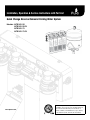
1
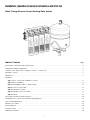
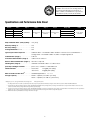
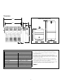
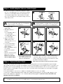
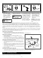
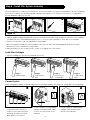
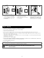
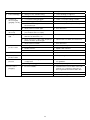
Installation, Operation & Service Instructions with Part List Quick Change Reverse Osmosis Drinking Water System Models: QCRO4V-50 QCRO4V-50-PL QCRO4V-75 QCRO4V-75-PL www.pura.com QCRO4V-50 system certified by WQA to NSF/ANSI 58 and CSA B483.1 for the reduction of the following substances, as verified and substantiated by test data: Arsenic V, Barium, Cadmium, Chromium III and VI, Copper, Fluoride, Lead, Radium 226/228, Selenium, TDS and Turbidity. Attention PURA Customer: This system is intended for use on potable water supplies or disinfected water containing cysts. Do not use where water is microbiologically unsafe or with water of unknown quality. If bacterial contamination is present, a recognized method of water disinfection is required. Check with your public works department for applicable local plumbing and sanitation codes. Follow your local codes if they differ from the standards used in this manual. The PURA Quick Change Drinking Water System contains a replaceable reverse osmosis membrane filter which is critical for the effective reduction of Total Dissolved Solids. The filtered water should be tested periodically to verify that the system is performing properly. Safe Practices Throughout this manual there are paragraphs set off by special headings. Note: Note is used to emphasize installation, operation or maintenance information which is important, but does not present any hazard. Example: Note: The nipple must extend no more than 1 inch above the cover plate. Caution!: Caution is used when failure to follow directions could result in damage to equipment or property. Example: Caution! Disassembly while under water pressure can result in flooding. Warning!: Warning is used to indicate a hazard which could cause injury or death if ignored. Example: Warning! Electrical shock hazard! Unplug the unit before removing the timer mechanism or cover plates! Serial Number The serial number is located on the rear of the R.O. manifold housing. Record this number on the warranty page located at the end of this manual. Note: Do not remove or destroy the serial number. It must be referenced on requests for warranty repair or replacement. Serial Number Label R - MM-DD-YY-XXXXXX Data Plate Label Containing Model # Date of manufacture Serial Code This publication is based on information available when approved for printing. Continuing design refinement could cause changes that may not be included in this publication. Warning! If incorrectly installed, operated or maintained, this product can cause severe injury. Those who install, operate, or maintain this product should be trained in its proper use, warned of its dangers, and should read the entire manual before attempting to install, operate or maintain this product. Installation, Operation & Service Instructions with Part List Quick Change Reverse Osmosis Drinking Water System Table of ContentsPage Specifications and Performance Data Sheet . . . . . . . . . . . . . . . . . . . . . . . . . . . . . . . . . . . . . . . . . . . . . . . . . . . . . . . . . . . . . . . . . . . 2 Suggested Installation Equipment . . . . . . . . . . . . . . . . . . . . . . . . . . . . . . . . . . . . . . . . . . . . . . . . . . . . . . . . . . . . . . . . . . . . . . . . . . . . 5 Overview of the PURA Quick Change RO System’s Components . . . . . . . . . . . . . . . . . . . . . . . . . . . . . . . . . . . . . . . . . . . . . . . . . . 6 Package Contents . . . . . . . . . . . . . . . . . . . . . . . . . . . . . . . . . . . . . . . . . . . . . . . . . . . . . . . . . . . . . . . . . . . . . . . . . . . . . . . . . . . . . . . . . 7 Preparation . . . . . . . . . . . . . . . . . . . . . . . . . . . . . . . . . . . . . . . . . . . . . . . . . . . . . . . . . . . . . . . . . . . . . . . . . . . . . . . . . . . . . . . . . . . . . . . 8 Installation Step 1 Select Component Installation Locations . . . . . . . . . . . . . . . . . . . . . . . . . . . . . . . . . . . . . . . . . . . . . . . . . . . . . . . . . . . . 11 Step 2 Faucet Installation . . . . . . . . . . . . . . . . . . . . . . . . . . . . . . . . . . . . . . . . . . . . . . . . . . . . . . . . . . . . . . . . . . . . . . . . . . . . . . . 12 Step 3 Install Adapter Valve on Water Supply . . . . . . . . . . . . . . . . . . . . . . . . . . . . . . . . . . . . . . . . . . . . . . . . . . . . . . . . . . . . . . 16 Step 4 Connect System Drain . . . . . . . . . . . . . . . . . . . . . . . . . . . . . . . . . . . . . . . . . . . . . . . . . . . . . . . . . . . . . . . . . . . . . . . . . . . . 16 Step 5 Install Reservoir Tank . . . . . . . . . . . . . . . . . . . . . . . . . . . . . . . . . . . . . . . . . . . . . . . . . . . . . . . . . . . . . . . . . . . . . . . . . . . . . . 17 Step 6 Install Filter System Assembly . . . . . . . . . . . . . . . . . . . . . . . . . . . . . . . . . . . . . . . . . . . . . . . . . . . . . . . . . . . . . . . . . . . . . . . 18 Step 7 Start Up . . . . . . . . . . . . . . . . . . . . . . . . . . . . . . . . . . . . . . . . . . . . . . . . . . . . . . . . . . . . . . . . . . . . . . . . . . . . . . . . . . . . . . . . 19 Performance and Technical Information . . . . . . . . . . . . . . . . . . . . . . . . . . . . . . . . . . . . . . . . . . . . . . . . . . . . . . . . . . . . . . . . . . . . . 20 Installing an RO to Service Other Water Using Appliances . . . . . . . . . . . . . . . . . . . . . . . . . . . . . . . . . . . . . . . . . . . . . . . . . . . . . . . 21 Service and Maintenance . . . . . . . . . . . . . . . . . . . . . . . . . . . . . . . . . . . . . . . . . . . . . . . . . . . . . . . . . . . . . . . . . . . . . . . . . . . . . . . . . . 22 Sanitation Procedure . . . . . . . . . . . . . . . . . . . . . . . . . . . . . . . . . . . . . . . . . . . . . . . . . . . . . . . . . . . . . . . . . . . . . . . . . . . . . . . . . . . . . . 23 Parts Breakdown . . . . . . . . . . . . . . . . . . . . . . . . . . . . . . . . . . . . . . . . . . . . . . . . . . . . . . . . . . . . . . . . . . . . . . . . . . . . . . . . . . . . . . . . . . 24 Troubleshooting . . . . . . . . . . . . . . . . . . . . . . . . . . . . . . . . . . . . . . . . . . . . . . . . . . . . . . . . . . . . . . . . . . . . . . . . . . . . . . . . . . . . . . . . . . . 26 Warranty Information . . . . . . . . . . . . . . . . . . . . . . . . . . . . . . . . . . . . . . . . . . . . . . . . . . . . . . . . . . . . . . . . . . . . . . . . . . . . . . . . . . . . . . 28 1 QCRO4V-50 system certified by WQA to NSF/ANSI 58 and CSA B483.1 for the reduction of the following substances, as verified and substantiated by test data: Arsenic V, Barium, Cadmium, Chromium III and VI, Copper, Fluoride, Lead, Radium 226/228, Selenium, TDS and Turbidity. Specifications and Performance Data Sheet Model # Part # QCRO4V-50 1340302-60 QCRO4V-50-PL 1340302-60-PL QCRO4V-75 1340303-60 QCRO4V-75-PL 1340303-60-PL Stage 1 Stage 2 Stage 3 Stage 4 Storage Tank Faucet Metal Tank - 3.2 Gallons Sediment Filter Activated Carbon Filter Reverse Osmosis Membrane Activated Carbon Filter Plastic Tank - 3.8 Gallons Metal Tank - 3.2 Gallons Chrome - AirGap or Standard Plastic Tank - 3.8 Gallons Daily Production Rate* L/day (G/day)����� 76.8 (20.3) Efficiency Rating**%����������������������������������� 12% Recovery Rating***������������������������������������� 21% Average Reduction**** % ������������������������� 85% Typical System Flow Sequence����������������� Sediment Filter Activated Carbon Prefilter Reverse Osmosis Membrane Storage Tank Activated Carbon Postfilter Dispensing Faucet Sediment Filter (Stage 1). . . . . . . ������������� 5 Micron Activated Carbon Prefilter (Stage 2) ������� Carbon Block 5 Micron Reverse Osmosis Membrane (Stage 3)��� Thin Film Composite Polishing Filter (Stage 4)����������������������������� Granular Activated Carbon or Carbon Block Specialty Cartridges Available����������������� ph Booster; “Scaleless” Scale Reduction Production Rate1 ��������������������������������������� QCRO4-50 36.5 gpd (138 L/day) QCRO4-75 55 gpd (284 L/day) 2 Ratio of Product to Flush Flow ����������������� Standard Applications 1:3 - 1:5 Storage Capacity��������������������������������������� Metal – Capacity 3.2 Gallon (12 Liters) Plastic - Capacity 3.8 Gallons (14.36 Liters) 1 Rating at 50 psi, 77°F, 750 mg/L TDS influent, without storage tank. 2 May vary with pressure. *The daily production rate is the volume of product water produced by the system per day and is determined by testing in accordance with the procedure outlined in NSF/ANSI Standard 58. **System’s Efficiency rating as verified by testing in accordance with NSF/ANSI standard 58. Efficiency rating means the percentage of the influent water to the system that is available to the user as reverse osmosis treated water under operating conditions that approximate typical daily usage. ***System’s Recovery rating as verified by testing in accordance with NSF/ANSI Standard 58. System’s Recovery rating means the percentage of the influent water to the membrane portion of the system that is available to the user as reverse osmosis treated water when the system is operated without a storage tank or when the storage tank is bypassed. **** Minimum TDS reduction per NSF/ANSI 58 is 187 mg/L. Influent TDS is 750 mg/L. 2 Dimensions Product Water Storage Tanks 15.8” 4.7” 14.3” 2.0” 19.8" 13.7" 13.1” 13.7" 9.2" 2.5” Notes Recommended Influent Water Characteristic Pressure 1. A booster is strongly recommended to improve the reduction of TDS. Higher pressures will help maintain the membrane’s maximum rejection performance. 40 - 100 psi Temperature 40 - 77 ºF Total Dissolved Solids (TDS)1 0 - 2500 ppm (0 - 2500 mg/L) pH 5 - 10 Chlorine2 0 - 3 ppm (0 - 3 mg/L) Chloramine 0 - 3 ppm (0 - 3 mg/L) Turbidity 0 - 10 NTU Hardness3 0 - 10 gpg Iron 0 - 1 ppm (0 - 1 mg/L) Bacterial Quality Potable 2. The reverse osmosis membrane used in these systems may be damaged by chlorine. These systems include activated carbon filters which protect the membranes by reducing chlorine. Influent chlorine should not exceed 3 mg/L. 3. A softener is strongly recommended for water over 10 gpg hard. Installing a system without a softener on water with hardness higher than 10 gpg will reduce the life of the membrane. 4. Additional information on factors that affect RO performance can be found in the “Performance & Technical Information” section. Table 1 3 Filter Cartridge Specifications Part # Purpose Micron Rating Sediment Filter 41407001 Sediment Reduction Carbon Block Filter 41407002 Carbon Block Filter - 50 Micron Working Temperature Working Range Pressure Range Rated Life* STAGE 207-689 kPa (30-100 psi) 6 Months 1 4-38° C (40-100° F) 207-689 kPa (30-100 psi) 6 Months 2 or 4 0.5 gal/min (1.9 liters/min) 4-38° C (40-100° F) 207-689 kPa (30-100 psi) 6 Months 2 2000 gallons (7570 liters) 0.5 gal/min (1.9 liters/min) 4-38° C (40-100° F) 207-689 kPa (30-100 psi) 6 to 12 Months 4 – 750 gallons (2835 liters) 0.5 gal/min (1.9 liters/min) 4-38° C (40-100° F) 207-689 kPa (30-100 psi) 6 to 12 Months 4 Ultra Fine Filtration 0.2 2000 gallons (7570 liters) 0.5 gal/min (1.9 liters/min) 4-38° C (40-100° F) 207-689 kPa (30-100 psi) 12 Months 3 41407009 Chlorine Taste and Odor, Particulate Reduction 1 750 gallons (2835 liters) 0.5 gal/min (1.9 liters/min) 4-38° C (40-100° F) 207-689 kPa (30-100 psi) 6 to 12 Months 2 or 4 41407010 Scale Reduction – 2000 gallons (7570 liters) 0.5 gal/min (1.9 liters/min) 4-38° C (40-100° F) 207-689 kPa (30-100 psi) 6 Months 1 or 2 Capacity Flow Rate 5 2000 gallons (7570 liters) 0.5 gal/min (1.9 liters/min) 4-38° C (40-100° F) Chlorine Taste and Odor 5 2000 gallons (7570 liters) 0.5 gal/min (1.9 liters/min) 41407006 Chlorine Taste and Odor 50 2000 gallons (7570 liters) GAC Carbon Filter 41407004 Polishing - Taste and Odor – pH Booster Filter Cartridge 41407007 Raise pH of water and removal of chlorine, taste and odor UF (Hollow Fiber) Membrane 41407005 Carbon Block – 1 Mic Filter Scale Reduction Part # Purpose RO Membrane 41407003 TDS Reduction 50 GPD RO Membrane 41407008 TDS Reduction 75 GPD Recovery (Product Water/ Inlet Water) 21% 21% TDS Reduction** Working Temperature Range Working Pressure Range (1) Rating*** Flow Rate Rated Life* STAGE 85% 50 gallons/day (189 liters/day) (No Storage Tank Attached) 0.5 gal/ min (1.9 liters/min) 4-38° C 50-120 psi (40-100° F) (345-828 kPa) 36 Months 3 85% 75 GPD (284 LPD) (No Storage Tank Attached) 0.5 gal/ min (1.9 liters/min) 4-38° C 50-120 psi (40-100° F) (345-828 kPa) 36 Months 3 * The performance and life of a reverse osmosis membrane or filter element is highly dependent upon pressure, temperature and dissolved solids (TDS). **Manufacturer’s Specification only with inlet conditions of 345 kPa (50 psig), 25° C (77° F), going to atmosphere. The actual volume of product water and rejection percentage will vary with differences from the test conditions that membrane ratings are based upon. (1) Pressure Regulator is recommended for feed water pressures exceeding 552 kPa (80 psig). 4 Performance Data Sheet Contaminant Reduction Table: Model QCRO4V-50 This system has been tested according to WQA S-300 for reduction of the substances listed below. The concentration of the indicated substances in water entering the system was reduced to a concentration less than or equal to the permissible limit for water leaving the system, as specified in NSF/ANSI 58. Influent challenge concentration mg/L Maximum permissible product water concentration mg/L Minimum % Reduction Average % Reduction Arsenic (+5)† 0.30 ± 10% 0.010 98.7 99.6 Barium 10.0 ± 10% 2.0 97.7 98.8 Cadmium 0.03 ± 10% 0.005 97.3 98.8 Chromium (+6) 0.3 ± 10% 0.1 97.6 99.1 Chromium (+3) 0.3 ± 10% 0.1 99.6 99.7 Copper 3.0 ± 10% 1.3 98.3 99.0 Fluoride 8.0 ± 10% 1.5 96.3 97.7 0.15 ± 10% 0.010 99.3 99.3 25 pCi/L ± 10% 5 pCi/L 80.0 80.0 Substance Lead Radium (226/228) Selenium 0.10 ± 10% 0.05 97.8 98.1 Turbidity 11 ± 1 NTU 0.5 NTU 96.7 98.9 TDS 750 ± 20% 187 84.5 85.1 † This appliance has been tested for the treatment of water containing pentavalent arsenic (also known as As(V), As(+5), or arsenate) at concentrations of 0.30 mg/L or less. This appliance reduces pentavalent arsenic, but may not remove other forms of arsenic. This appliance is to be used on water supplies containing detectable free chlorine residual at the appliance inlet or on water supplies that have been demonstrated to contain only pentavalent arsenic. Treatment with chloramine (combined chlorine) is not sufficient to ensure complete conversion of trivalent arsenic to pentavalent arsenic. Please see the Arsenic Facts section. Arsenic Facts Arsenic (abbreviated As) is found naturally in some well water. Arsenic in water has no color, taste, or odor. It must be measured by a laboratory test. Public water utilities must have their water tested for arsenic. You can get the results from your water utility. If you have your own well, you can have the water tested. The local health department or the state environmental health agency can provide a list of certified labs. The cost is typically $15 to $30. Information about arsenic in water can be found on the Internet at the U. S. Environmental Protection Agency website: www.epa.gov/safewater/arsenic.html. There are two forms of arsenic: pentavalent arsenic (also called As(V), As(+5), and arsenate) and trivalent arsenic (also called As(III), As(+3), and arsenite). In well water, arsenic may be pentavalent, trivalent, or a combination of both. Special sampling procedures are needed for a lab to determine what type and how much of each type of arsenic is in the water. Check with the labs in your area to see if they can provide this type of service. Reverse osmosis (RO) water treatment systems do not remove trivalent arsenic from water very well. RO systems are very effective at removing pentavalent arsenic. A free chlorine residual will rapidly convert trivalent arsenic to pentavalent arsenic. Other water treatment chemicals such as ozone and potassium permanganate will also change trivalent arsenic to pentavalent arsenic. A combined chlorine residual (also called chloramine) may not convert all the trivalent arsenic. If you get your water from a public water utility, contact the utility to find out if free chlorine or combined chlorine is used in the water system. The QCRO4V-50 system is designed to remove pentavalent arsenic. It will not convert trivalent arsenic to pentavalent arsenic. The system was tested in a lab. Under testing conditions, the system reduced [0.30 mg/L (ppm) or 0.050 mg/L (ppm)] pentavalent arsenic to 0.010 mg/L (ppm) (the USEPA standard for drinking water) or less. The performance of the system may be different at your installation. Have the treated water tested for arsenic to check whether the system is working properly. The RO component of the QCRO4V-50 system must be replaced every three (3) years to ensure that the system will continue to remove pentavalent arsenic. The component identification and locations where you can purchase the component listed in this installation/operation manual 5 Suggested Installation Equipment 1 2 3 4 6 7 8 5 Recommended Tools 1. Utility Knife 12 10 2. Flathead Screwdriver 3. Phillips Screwdriver 11 4. Center Punch 5. 7/8” Stepped Drill Bit 6. Finish Hole Saw 7. Porcelain Saw 8. 1/8” & 3/8” Drill Bits 9. Heavy Duty Drill 10. Work Light 11. 2 Adjustable Wrenches 12. Pressure Gauge Figure 1 6 Overview of the PURA Quick Change RO System’s Components Manifold Assembly The manifold assembly serves as the functional hub of the PURA system by directing the flow through each of the system’s main components. Sediment Filter The sediment filter screens out particulate material, such as dirt, sand, or rust, which may clog the other filters in the system. Activated Carbon Prefilter The activated carbon prefilter reduces chlorine which may damage the RO membrane filter. It must be regularly checked and/or replaced to prevent premature membrane failure and poor water quality. Reverse Osmosis Membrane The RO membrane (4) reduces dissolved substances and other microscopic impurities. It consists of a membrane envelope wound around a perforated tube. Product water diffuses through the membrane to the inside of the envelope where it flows to and is collected by the tube. Impurities are flushed away in the drain stream. The RO membrane featured in the PURA system offers exceptional contaminant rejection, application versatility, and long life. The membrane material is sensitive to an attack by chlorine. The activated carbon filter must be maintained properly to prevent premature failure of the RO membrane. 9 For long term storage the RO membrane should be refrigerated to maximize performance once used. DO NOT ALLOW TO FREEZE. Note: This preservative must be flushed from membrane before use. If ingested it may cause irritation of the gastrointestinal tract, colic, diarrhea, or other similar symptoms. The manufacturer recommends discarding all the product water for at least one hour of operation before drinking or use in food preparations. WaterGroup highly recommends discarding the product water for a full 24 hours to flush the preservative and to properly hydrate the membrane for maximum performance. Figure 2 Polishing Filter The polishing filter (5) adsorbs any residual tastes and odors just before the water is delivered through the faucet. Drain Line Flow Control The flow control assembly or concentrate flow control (6) regulates the flow rate of the flushing (drain) stream and to maintain pressure in the RO membrane filter. Automatic Shutoff The automatic shutoff (7) automatically stops the flow of water through the PURA system when the storage tank is full. Dispenser Faucet The PURA faucet (8) allows the product water to be drawn from the system with a simple rotation of the handle. This air gap style faucet prevents the unit from siphoning drain water back into the system. It features a built-in siphon break for concentrate discharge as required by most plumbing codes. Storage Tank The storage tank (9) collects and stores the water produced by the RO system. A compressed air diaphragm drives the water to the polishing filter and faucet. The ball valve (11) provides a convenient way to lock water in the tank during transport and filter changes. Note: Cleanliness is essential in the Preparation procedure. Be sure to wash your hands thoroughly before handling filters. The use of surgical gloves is strongly recommended. 7 Package Contents 6 1 8 OR 2 3 4 7 5 9 17 14 11 19 21 2X 15 12 10 18 16 Figure 3 20 3X 13 1. RO Manifold with Flow Control 9. Drain Saddle (1/4” or 3/8”) 17. 4X #10 Phillips Self Tapping Screws 2. Sediment Filter 10. Tank Shut-off Valve 18. Teflon Tape 3. Carbon Block Filter 11. Piercing Saddle Valve 4. RO Membrane 12. 2X Locking Clip (3/8”) 19. 1/4” Tubing ( 4 ft. White; 4 ft. Red) 5. Carbon Block Filter 13. 2X 3/8” Elbow 6. Metal or Plastic Storage Tank 14. Faucet Adapter 7. Tank Base (Optional) 15. Locking Clip (1/4”) 8. Faucet and Hardware 16. 1/4” Elbow 8 20. 3/8” Tubing (4 ft. White; 4 ft. Red; 4 ft. Blue) 21. Installation Template Sheet 11X17 Product Information This manual covers the technical aspects of PURA Quick Change drinking water systems. It is important to read this manual thoroughly so that you can properly apply, install, and service these systems. The substances reduced by this system are not necessarily in the customer’s untreated water. Warranty A limited warranty is extended to the original end user from WaterGroup. This warranty is printed on the back cover of the Owner’s Guide. Application Guidelines The PURA system is designed for use on potable water supplies meeting the guidelines outlined in Table 1. The system should be installed on a home’s cold water line. The flushing stream should discharge through an approved siphon break. Installation of this system must comply with state and local laws and regulations. Package Content The PURA system is shipped from the factory in carton: Note: The filter elements are shipped in their own sealed packaging. This will help to simplify preparation of the system and to maximize the shelf life of the RO membrane element. Preparation Tubing Connectors The PURA system features reliable and convenient push-to-connect tubing connectors. Tubing is easily connected and disconnected from these fittings as follows. Quick-Connect Fitting Insertion & Removal of Plastic or Copper Tubing 2. Tube is secured in position. 3. Push in collet from both sides to release tubing. 1.Simply push in tube to attach. Figure 4 Connect: Cut the tubing squarely with a sharp knife. Be careful not to crush the tubing. To avoid leaks, make sure the tubing end is smooth and free of burrs and abrasions. Lubricate the end of the tube with water or a light coat of silicone and push the tube end firmly into the fitting. You should feel it push past the O-ring. Avoid bending the tubing sharply away from the fitting. Disconnect: Hold the collar against the fitting body and pull the tube from the fitting. In the unlikely event that the connection leaks, remove and recut the tubing. Check the inside of the fitting for debris or O-ring damage. Reconnect. Push-to-connect tubing connectors grip the outside diameter of the tube. To help assure a reliable connection, it is important to use high quality tubing with a consistent outside diameter. 9 1.Cut tube squarely with a sharp knife. Verify Flow Control Location Storage Tank Preparation Flow Restrictor The RO manifold comes attached with the elbow fitting flow control. This flow control is attached to the manifold by quick disconnect fitting which allows it to be easily changed. Verify it is properly located in the outlet next to the symbol. Note: C hanging the air pressure will alter the amount of water stored in the tank. Increasing the pressure will decrease capacity while decreasing pressure will increase capacity. Figure 5 Install Tank Shut-off Valve 1 3 2 1.Apply teflon (PTFE) tape to threaded fitting at top of tank. Wrap tape around clockwise 3 to 6 times for a good seal. 2. Attach shut off valve. 1 Warning! Do not use the tank ball valve to lift or carry the tank. 2 1.Attach Shutoff valve 3/8” White Tubing 3.Connect white 3/8” tubing to tank. Metal Tank Figure 6A Plastic Tank Figure 6B 2. Slide compression nut over end of 3/8” white tubing, place the insert in the end of the tube. Connect the white 3/8” tubing to tank using the compression nut. 10 Installation The exact placement of the components will vary by installation. Although shown beneath a sink, it may be installed in a basement, crawl space, or in an adjacent cabinet. Regardless of where the system is installed, the flow sequence described by (figure 7) must be observed. The PURA drinking water system is designed to be mounted near a sink for easy access to cold water and drain lines. Lengths of 1/4-inch and 3/8-inch OD plastic tubing will be required to make this installation. Evaluate the installation site to determine the easiest path for the plumbing to follow. Take care to make the installation as neat as possible. Pura Faucet STEP 2 3/8” Drain Line from Air Gap (Red) STEP 3 Drain Connection 1/4” Drain Line to Air Gap (Red) The additional Point of use connection (Icemakers etc) can be tapped from here with the use of reducing Quick Connect Tee (14” X 3/8” X 3/8”) (Part # PP30121208W). Cold Water Supply STEP 4 RO Manifold STEP 6 3/8” Product Water Line (Blue) 1/4” Feed Line (White) 3/8” Tank Line (White) Pressure Tank STEP 5 Figure 7 Note: Install the 3/8” red drain line from the air gap faucet to the drain adapter so that it runs downward with no loops or low spots. Otherwise the unit will overflow at the air gap siphon break built into the faucet, or make irritating gurgling sounds. For standard faucet (non-air gap) installations simply route the drain line directly to the drain connection. 11 The following steps will enable you to install the system quickly and orderly. Some variation may be necessary depending on the installation. See page 4 for a check list of tools and materials. Typical installations follow this sequence: 1. Select Component Installation Locations 2. Faucet Installation 3. Install Adapter Valve on Water Supply 4. Connect System Drain 5. Install Reservoir Tank 6. Install Filter System Assembly 7.Start-Up Step 1 – Select Component Installation Locations • Dispenser Faucet – The faucet is designed to be mounted on the rear lip of the sink. It may be installed in an existing sprayer attachment hole or in a hole drilled at the time of installation. It may also be mounted to an adjacent counter top. It should be positioned so that water is dispensed over the sink. A 7/8” diameter hole is required. • Important considerations: • Access to the bottom (undersink) of the faucet is required for attachment of product water line. • There should be no undersink obstructions which would prevent smooth tubing runs to the drain connection, or RO module assembly. • Filter System Assembly – The filter system assembly is designed to be mounted on any rigid vertical surface such as a cabinet sidewall, sheetrock in exposed stud. It should be positioned such that there is access to an inlet water source and drain. The installation should also allow convenient access for servicing. • Inlet Water Supply Connection – Once a location is chosen for installation of the filter system assembly, select a nearby cold water line to provide the water source for the system. Note: Follow all local plumbing codes when connecting to service water. • The Reservoir Tank – Position the reservoir tank near the faucet for optimum convenience. The reservoir tank will weigh about 28 pounds (13 kg) when full of water, so it must be positioned on a stand. The reservoir operates best in the vertical position, but it will operate on its side. • Drain Connection – The most convenient entry to the drain is directly above the P-trap of the kitchen sink. However, the drain water from the system can be connected to adjacent sinks or a floor drain. Extra care should be taken when entering drains near dishwashers or food waste disposals as back flow may occur through the air gap and cause flooding. Note: Follow all local plumbing codes when connecting to drain. 12 Step 2 – Faucet Installation To simplify its access and installation, we suggest you install the faucet on the rear lip of the sink. It should be evenly positioned with the sink faucet and spray attachment. Should the spray faucet hole not be available for the installation, the sink must be drilled. Note: It is recommended retaining the services of a professional counter top craft person when a hole is needed in granite or other specialty counter top materials. Sink Drilling Instructions Stainless Steel Sink 1. Select and mark the proper faucet location. 3. Drill a 7/8” hole in the sink using a stepped 7/8” drill bit. If no stepped bit is available, start by drilling a 1/4” hole. Using this hole as a starting point progressively drill larger holes. Increase drill size by 1/8” until you reach a 7/8” hole. 2. Center punch hole to provide a starting point for your drill. Porcelain Enamel Sink Follow these basic guidelines when drilling a porcelain sink: Pilot Drill Spring Loaded Porcelain Saw Penetrate the porcelain to the base material. Protect the surrounding porcelain material. Finish Hole Saw Use the appropriate tool to drill the base material. One proven tool is the Relton porcelain cutter kit when used with a slow speed drill (300-400 rpm). • Drill a pilot hole through the porcelain and base material with the carbide tip drill. • Build a putty dam around the drill area. Add enough water to lubricate cutters and reduce cutting noise. • Insert the porcelain cutter into the drill. Place the drill tip in the pilot hole. Check for free movement. • Apply light pressure to the cutter tool and start the drill motor at low speed (300-400 rpm). When the initial cut has been made in the porcelain, speed may be increased. After a complete ring has been cut through the porcelain, change over to the metal cutter. Avoid contacting the outer rim of cut porcelain when drilling. Caution! Avoid high drill speed during penetration of porcelain. A single speed drill can be used at a slow speed by switching it on and off quickly. • Use a slow speed and light pressure to cut away the porcelain. • Stop when you reach the metal under the porcelain. Remove the cutter and clean the porcelain chips from the surface. Continue cutting through the metal. Note: C eramic tile counters should be treated like porcelain when penetrating the surface, then treated as metal to complete the hole with carbide drills. Formica countertops can be drilled with a high-speed wood drill. 13 Air Gap Faucet (Standard) 3/8” Red Tubing 1/4” Red Tubing Faucet 1 2 Base (Remove white protective film.) Rubber Washer 3 4 Lock Washer Nut 6 7 5 Split Washer Spacer (Optional) 8 Faucet Adapter Drain Line from Faucet (3/8” Red Tubing) Figure 10 Drinking Water Line to Faucet (3/8” Blue Tubing) Drain Line from RO Manifold (1/4” Red Tubing) Note: T he spacer is required for stainless steel sinks and thin counter tops. If sink is being installed on a thick (5/8” or thicker) counter the spacer is not required. Remove white protective film from faucet base. 14 Non Air Gap Faucet (Optional) 1 2 Base (Remove white protective film) 3 Lock Washer Faucet Adapter 4 6 5 8 7 Faucet Small Rubber Washer Large Rubber Washer Plastic Washer Nut Drinking Water Line to Faucet (3/8” Blue Tubing) Standard Faucet Installation 1. R emove white protective film from faucet base. Install faucet body, small rubber washer, metal base, and large rubber washer above sink (items 1-4). 2. Install plastic washer, lock washer and nut (items 5-7) onto faucet stem below sink and tighten. Be sure to properly align the faucet. 3. Install the faucet adapter (item 8). Connect the 3/8" blue tubing to the faucet adapter. Note: If installing a standard faucet the red 1/4” drain line will be installed directly to the drain. Disregard the instructions on the following page. 15 Air Gap Faucet Installation Remove white protective film from faucet base. Verify faucet body, metal base, and rubber base washer are in place above sink (Items 1, 3, and 2). Lower faucet into mounting hole and place faucet over hole. Install slotted washer, spacer, faucet washer, and nut onto faucet nipple below sink and snug them up (Items 4, 5, 6, 7 and 8). Be sure to properly align faucet before tightening. Do not over tighten. Install faucet connector (Item 9), packaged with faucet, onto faucet nipple. The spacer is typically necessary on stainless steel sinks and thin counter tops. If counter top or sink is too think (5/8” or thicker) remove the spacer from the installation. Caution! Plastic Parts will break if screws are over tightened! Tubing Connections 1. At the bottom of the faucet assembly you will find three tubing connections; 2 are barbed and one is a push in type fitting. 2. For the Air gap you will use the 2 barb fittings, the smaller fitting is for the 1/4” tubing and will be connected to the RO system. The larger barb fitting will use the 3/8” tubing and will be connected to the drain. Note: If you have difficulty fitting the tubing onto the barbed fittings, try running hot water over the end of the tubes. 3/8” Red Tubing 1/4” Red Tubing Note: C ut the tubing to be longer than what you will need because you will be able to trim it after you install the faucet assembly. Prepare the tubing with a fresh cut and make sure that it is free of dirt and any foreign materials. 9 Faucet Adapter Product Line from RO Manifold (3/8” Blue Tubing) 3.Take another length of 3/8” tubing and make sure it is has a fresh cut and is free of foreign materials and any scratches on the outside surface. Install the tubing into the push in type fitting at the base of the faucet. Make certain that it is inserted all the way in; once inserted give it a slight pull to make sure it is locked into the fitting. You have now completed the tubing connections. Note: T o disconnect tubing from the product water fitting, hold the collet firmly against fitting body and pull the tube from the fitting. Repeated assembly and disassembly will cause wear to the inner body. Visually inspect for excessive wear and replace the inner body as needed to protect against any leaks. Cleaning the Faucet Wipe the faucet with a soft cloth, avoid abrasive cleansers. 16 Step 3 – Install Adapter Valve on Water Supply 1. L ocate shut off valves on water lines under sink. To identify hot & cold supply pipes, turn on both faucets and let water run. Hot water pipe will be the warmer pipe. Turn off cold water supply valve. Open sink faucet to drain line. Some mixing faucets may require shutting off the hot water valve as well. 1 OK Caution! Do not turn valve handle before or during installation of saddle valve. Be sure piercing lance does not protrude prior to installing valve. Caution! If no shut off valve is installed under sink, close main water valve. Do not install feed water assembly on hot water line. 2. H old saddle valve against pipe. NO! 2 3 4 3. S lide back plate into position. •U se small radius side for 3/8”copper pipe. •U se large radius side for 1/2”copper pipe. 4. T ighten screw firmly so saddle valve is held securely in place. Do not crush tube. 5. C onnect feed tubing to valve body using compression fitting. • Slide nut and plastic sleeve onto tubing. • Install insert into plastic tubing. • Slide into valve body and tighten nut securely. NOTE: Do not use brass sleeve on plastic tubing. 5 Insert Plastic Sleeve Nut 1/4” Tubing 6 7. Once all lines are connected to the RO system turn on cold water supply. Turn Valve counter-clockwise and check for any leaks. Run water from the faucet to clear any debris caused by installation. 6. Turn handle clockwise until firmly seated and piercing valve has extended fully. Step 4 – Connect System Drain NOTE: If flow from sink faucet isreduced, clean faucet aerator. Plumbing codes require that the drain from reverse osmosis drinking water systems be discharged through an air gap siphon break. The faucet incorporates an air gap into its body. The discharge from the air gap must be connected to the plumbing system for proper drainage. This connection can usually be made beneath the sink. Incorrect installation may result in overflow of the air gap or excessive noise. If the concentrate water is discharged to an open drain, the air gap may not be necessary. For Air Gap installations select the 3/8” saddle, for Standard installations use the 1/4” saddle. Connections to undersink plumbing can be made with a saddle clamp designed to accept the drain tubing from the faucet. Drain Saddle Kit is supplied for 1-1/2” undersink drain plumbing (Figure 14). Be sure to check and follow local plumbing codes prior to installation. Note: F or installation in Massachusetts, Plumbing Code 248 CMR shall be adhered to. Consult your licensed plumber for installation of this system. The use of saddle valves is not permitted in Massachusetts. 17 2 1 3 4 Figure 14 1. Install the drain saddle valve on to the drain pipe. See figure 7 on page 9 for its location. Use 3/8” saddle for air gap faucets or 1/4” saddle for standard faucets. 2. Tighten the clamps with the help of the two bolts. Warning! Do not drill through both sides of pipe!. Warning! Do not overtighten. 3. For standard faucets drill a 1/4” hole through one side of the pipe. For air gap faucets drill a 3/8” hole. The drill should be kept straight and centered to avoid damaging the saddle valve. Do not drill through both sides of the pipe! 4. Attach 3/8” or 1/4” red tube by slipping the tube through the black compression nut and hand tighten the nut on to the saddle valve. CAUTION: The drill should be kept straight and centered to avoid damaging the saddle valve. Many homes are equipped with disposals and dishwashers. Special care must be taken when these appliances are present to prevent improper air gap performance. Home drain plumbing must be free of any blockage since this may cause a backup of dishwasher and disposal waste into the air gap outlet tube and result in improper air gap performance. To perform a simple drain check, fill the sink basin with several inches of water, pull the plug, and observe the drainage. If water backs up into the second sink (if present), or if drainage is slow or there is excessive gurgling, drain blockage may be present. Undersink drain plumbing usually resembles one of the following descriptions. In all cases, the drain tubing from the air gap (RO outlet) should run downward, free of dips and loops. The air gap outlet must not be connected to the effluent side of the trap. This can vent sewer gas, which will produce foul odors. Single basin sink without disposal • Connect the RO outlet to the tailpiece directly beneath the sink. • If a dishwasher drain connection is present, the RO outlet must be connected above it. Single basin sink with disposal • Connect the RO outlet to the dishwasher drain port on the disposal if available. • If the dishwasher drain port is not available, other arrangements must be made such as running the RO outlet to a basement sump. • Do not connect the RO outlet to the plumbing below the disposal. Double basin sink with disposal, single trap • The fitting which joins the drains from the disposal and second sink should be directional. If not, then we recommend that it be replaced. • Connect the RO outlet to the tailpiece just below the second sink. • If a dishwasher drain is present and cannot be relocated, the RO outlet must be connected above it. • Do not connect the RO outlet to the horizontal plumbing between the two sink drains. Sink Sink Disposal Do not install here Drain Line from Air Gap (Air Gap Only) Install here Double basin sink with disposal, double trap • Connect the RO outlet to the tailpiece just below the second sink. • If a dishwasher drain is present and cannot be relocated, the RO outlet must be connected above it. Step 5 – Install Reservoir Tank Place the reservoir tank in the location previously selected. 18 Step 6 – Install Filter System Assembly The mounting bracket contains four mounting slots. The holes are sized to accept #10 round head wood screws (supplied). Some types of surfaces such as particle board or drywall, may require the use of plastic screw anchors or toggle bolts to provide adequate support for the unit. 1 2 3 4 12" Figure 15 1. T ape the paper template included with this unit to the wall with the base of the template on the bottom of the cabinet (or higher). Be sure to leave adequate space (8 1/2” or more from the centerline) on both sides of the template. 2. Drill 1/8” hole at each location as indicated on the template. 3. R emove template. Thread one of the included wood screws into each hole leaving approximately a 1/2” space between the screw head and mounting surface. 4. Hang the bracket on the mounting screws. If unit is loose, tighten the screws further. Install Filter Cartridges 1.Twist the cartridge to lock it into the manifold. (as shown) Stage 1 Sediment Filter Stage 3 Reverse Osmosis Membrane Stage 2 Carbon Block Filter Stage 4 Carbon Block Filter Connect System When cutting plastic tubing, use a sharp utility knife. Cut the tubing squarely. See page 7 for cutting and connecting tubing. 2 1 White 1.Connect quick connect elbows to the three open connection locations on the unit. Firmly push the fittings into place, then pull back lightly to lock them in. 2.Connect 1/4-inch OD white plastic tubing from the feed water supply source to the system inlet on the manifold. 19 3 Blue 3.Connect 3/8-inch OD blue plastic tubing from the product water faucet to the manifold. 5 4 6 Red 4. Connect the 1/4” OD red tubing from the air gap inlet of the faucet to the concentrate outlet on the RO manifold. 5. Connect the 3/8” OD white product water tube from the tank to the manifold. 6. Attach locking clips to each white elbow fitting. Do not attach one to the blue flow control. Clips should slide in behind collet on the fittings. Step 7 – Start-Up 1. Sanitize the storage tank (see page 20 for sanitization procedure). 2. Check system to verify all components are correctly installed 3. Open inlet valve and tank valve. 4. Check system thoroughly for leaks. If any are found, shut off both inlet and tank valves and correct the issue. 5. Allow system to run & fill tank for 1-2 hours. You will hear the water running to drain while the unit is running. Once the water stops running to drain the tank is full. 6. Open faucet to flush carbon fines & sanitization solution. Once the flow begins to slow down (around 20 minutes after opening) turn off the faucet. 7. Allow the tank to fill completely again. 8. Once full, open the faucet and allow the water to run for 24 hours to break-in the RO membrane and completely flush the system. This will allow your system to run at optimal efficiency. 9. Close faucet and allow tank to fill. 10. System is ready to use Note: It is normal if the air gap faucet makes gurgling noises and drips small amounts of water during start-up procedure. This should subside once start-up procedure is complete. Warning! Do not drink water produced by the system until the start-up procedure has been followed completely! 20 Performance & Technical Information The performance of the PURA system can be characterized and judged by the quality and quantity of the water produced by the system. By measuring the contaminant removal performance and flow rates of the system, its operating status can be easily evaluated. Factors Which Affect Performance Performance of the reverse osmosis membrane is affected by several factors which must be considered when judging the condition of the system. The main factors which affect system performance are pressure, temperature, total dissolved solids level, recovery and pH. Pressure Water pressure affects both the quantity and quality of the water produced by the RO membrane. Generally, the more water pressure, the better the performance of the system. Be careful not to go below 40 psi or exceed 100 psi, the minimum and maximum operating pressure of the system. Temperature The reverse osmosis process slows with decreasing temperature. To compensate, a temperature correction factor is used to adjust the actual performance of the RO membrane filter to the standard temperature of 77°F (25°C). This allows the performance of the unit to be accurately gauged against published standards. Temperature does not affect the concentrate flow rate. Total Dissolved Solids The minimum driving force which is necessary to stop or reverse the natural osmosis process is termed osmotic pressure. As the total dissolved solids level of the feed water increases, the amount of osmotic pressure increases and acts as back pressure against the reverse osmosis process. Osmotic pressure becomes significant at TDS levels above 500 mg/L (ppm). Hardness Hardness is the most common membrane foulant. If ignored, this relatively harmless component of feed water will scale a membrane over time. Use of a softener will reduce the fouling effect on a membrane. One way to detect too much hardness in the feed water is the weight of a membrane installed for a period of time. A fouled membrane (dried) will weigh significantly more than a new membrane. The increase in weight is a result of precipitated hardness inside the membrane. Iron Iron is another common membrane foulant. There are a variety of types of iron, some of which cannot be removed by an iron filter. Clear water iron can be removed more effectively by a softener. Particulate iron can be removed more effectively by a 1 micron filter. Organic-bound iron can be removed only by activated carbon or macroporous anion resin. If there is enough iron to exceed the EPA secondary drinking water standard and softening the water is not an option and the iron is soluble, then an iron filter is appropriate. If none of these are an option then regular replacement of membranes will have to be accepted. Note: Increased weight of the RO cartridge may be a foulant other than hardness. Product Water Recovery Product water recovery plays an important role in determining membrane and system performance. Recovery refers to the amount of water produced in relation to the amount of water sent to drain. The standard calculation is: % Recovery = Product Water ÷ (Product Water + Waste Water) x 100 The system uses a flow control assembly to restrict the flow of waste water to the drain. This restriction helps maintain pressure against the membrane. The sizing of the flow control assembly determines the recovery rating of the system. The system is manufactured with a recovery rating designed to be around 25%. Depending on temperature, pressure and tolerances the actual recovery value may be slightly different for each system. Performance Measurements When collecting water samples from the manifold, insert a short 2”-3” length of tubing into the fitting on the manifold to catch the water sample. TDS can be measured with an electronic TDS meter. PN 66760 21 Installing an RO to Service Other Water Using Appliances Pressure, Pressure, Pressure If you are installing a service line from an RO storage tank to an appliance with a minimum pressure requirement then you may need to consider the following options so as not to operate below the operating limits of that appliance. Installation of a booster pump (92325) Placing this pump before the RO will increases overall pressure to the system. If you boost the water pressure from 40 to 80, then the full pressure in the storage tank will be around 53 psi. Increasing the overall pressure in the system will allow more volume to be drawn from the tank before the pressure dips below a shutoff value. Pura Faucet 3/8” Drain Line from Air Gap (Red) Drain Connection Cold Water Supply 1/4” Drain Line to Air Gap (Red) The additional Point of use connection (Icemakers etc) can be tapped from here with the use of reducing Quick Connect Tee (14” X 3/8” X 3/8”) (Part # PP30121208W). RO Manifold Booster Pump 3/8” Product Water Line (Blue) 1/4” Feed Line (White) 3/8” Tank Line (White) Pressure Tank Figure 18 ADDITIONAL POINT OF USE CONNECTION (Fittings and tubing for additional point of use connection is not supplied with this system) NOTE: Icemakers typically use 1/4” tubing as feed line. NOTE: Reduce the 3/8” Line to 1/4” as close as possible to the additional point-of use device to minimize flow loss. 1. To connect an additional point of use (icemaker, extra faucet in wet bar and/or another use for treated water), place a “tee” connector (P/N PP30121208W) in 3/8” blue line between faucet and RO Module. 2. Connect “tee” to point-of-use with 1/4” tubing (P/N 92600). Connect tubing to point-of-use. If point of use connection requires 3/8" fitting, use of 3/8" Tee (Part # 92403) and 3/8" tubing (Part # 87600) 22 Service and Maintenance Service Schedule To keep the PURA system operating properly, it is necessary to change the filters and sanitize the system periodically. Typically, this should be done on an annual basis. Service frequency may vary depending on local water conditions. High sediment, chlorine, turbidity, or hardness levels may require more frequent service. Use the following as a guide. As needed Clean the faucet with a soft cloth, avoid abrasive cleaners. At least once in 6 months Replace • Stage 1 Sediment Filter (41407001) • Stage 2 Carbon Block Filter (41407002) At least once in 12 months Replace • Stage 4 Carbon Block Filter (41407002) Check • TDS of incoming and product water Sanitize the system • Tank Pressure Note: T he reverse osmosis membrane (Stage 3) Part # 41407003 is recommended to be changed once every three years or as needed. 23 Metal Tank Sanitization Procedure Tank Pressure Check 1.Turn off water supply to your RO system by turning off the adapter valve. Open the faucet to drain the storage tank. 3. Using a clean eye dropper insert 1/2 teaspoon of hydrogen peroxide or common household bleach into the tube. 2.Once the tank has emptied. Disconnect the tube from the ball valve on the storage tank. 4. Reconnect the tube to the ball valve. Follow the start up procedure and drain the first two full tanks of water. Plastic Tank Sanitization Procedure 1. Turn off incoming water supply to RO. 2.Open RO Faucet and allow water to drain from the tank until it is completely empty. 3.Check that air pressure is between 5-7 psi using an air pressure gauge. 4.If the pressure is low use a bicycle pump to increase pressure to 5-7 psi. 5. Follow startup procedure. Tank Pressure Check 1.Turn off water supply to your RO system by turning off the adapter valve. Open the faucet to drain the storage tank. 3. Using a clean eye dropper insert 1/2 teaspoon of hydrogen peroxide or common household bleach into the tube. 2.Once the tank has emptied. Disconnect the tube from the ball valve on the storage tank. 4. Reconnect the tube to the ball valve. Follow the start up procedure and drain the first two full tanks of water. 24 1. Turn off incoming water supply to RO. 2.Open RO Faucet and allow water to drain from the tank until it is completely empty. 3.Check that air pressure is between 5-7 psi using an air pressure gauge. 4.If the pressure is low use a bicycle pump to increase pressure to 5-7 psi. 5. Follow startup procedure. Parts Breakdown 10 2 3 9 4 8 1 5 6 # Item # 1 134040R 7 6 Description Qty. Manifold, Quick Change RO, 4 Stage 1 2 92223 Valve, Auto Shut-off 1 3 41407553 Fitting,Check Valve,QCRO 1 4 41407552 Fitting, T-Connector, QCRO 1 5 41407001 Cartridge, Quick Change Sediment Filter - Stage 1 1 6 41407002 Cartridge, Quick Change Carbon Block - Stage 2 & 4 2 7 41407003 Cartridge, Quick Change 50GPD TFC Membrane - Stage 3 1 8 33501064 Elbow,1/4” Stem 1 9 33501071 Elbow,3/8” Stem 2 10 92800 Fitting, Drain Flow Control 1 25 Other Parts 1.Storage Tank – Part # 92371 2.Faucet & Hardware – Part # 92192 3.Drain Saddle – Part # 92160 4.Tank Shut-off Valve – Part # PPSV501222W 5.Piercing Valve - Part # 92276 6.2x Locking Clip (3/8") – Part # 92346 7.Faucet Adapter – Part # 92652 8.Locking Clip (1/4") – Part # 92345 9.4x #10 Phillips Self Tapping Screws 10.Teflon Tape 11.1/4" Tubing (4ft White – Part # 115200; 4ft Red – Part # 115201) 12.3/8" Tubing (4ft White – Part # 92663; 4ft Red – Part # 87604; 4ft Blue – Part # 87600) 13 O-ring, Small – Part # 41407554 14.O-ring, Medium – Part # 41407555 15.O-ring, Large – Part # 41407556 16.Replacement Filter Head – Part # 92804 17.Compact Elbow – Part # 41407558 18 Front Check Valve – Part # 41407557 19.1/4” Elbow – Part # PP0308W 20.3/8” X 1/4” Stem Adapter – Part # PP061208W 1 2 4 3 7 6 11 9 5 8 10 13 14 12 16 15 2X 3X 17 19 26 18 20 Troubleshooting Guide If a problem cannot be corrected through the use of this troubleshooting guide please have the following information ready prior to calling the 1-800 number on the back of this manual: • Serial # • Model # Problem Possible Cause Remedy 1.Insufficient quantity of product water available to service. a. Service greater than unit’s specified output. a. Use optional large tank for more storage capacity. b. Insufficient feed water flow. b. 1. 2. 3. c. Insufficient feed water pressure c. 1. Same as (b) above. 2. Change in line pressure; install booster pump. d. Increase in feed water TDS. d. 1. Same as (a) above. 2. Install booster pump. e. Reduced feed water temperature. e. Same as above. f. f. 2. Poor product water quality. 3. Bad tasting product water. Plugged prefilter. Clogged shut-off valve or feed tubing; clean out or replace. Clogged prefilter; replace. Clogged manifold; clean or replace. Replace filter element. g. Plugged polishing filter. g. Replace polishing filter. h. RO membrane fouled with sediment. h. Replace RO membrane and prefilter elements. i. i. Shutoff malfunction. Clean or replace shutoff. a. All of (1) above except (a) and (e). a. All of (1) above except (a), (e), and (g). b. RO membrane filter worn out. b. Replace RO membrane. d. Shutoff malfunction. d. Replace shutoff. a. Decrease in product quality; see (2) above. a. Same as (2) above. b. Foreign matter in storage tank. b. Clean, sanitize, and flush storage tank. c. Polishing filter exhausted. c. Replace polishing filter d. Plugged capillary tube. d. Replace capillary tube; replace prefilter, if necessary. e. Storage tank bladder is ruptured. e. Replace storage tank and check precharge pressure. 27 Problem Possible Cause Remedy 4. External leakage. a. Tubing not fully seated in fitting a. Check all fittings for tightness. b. Tubing abraded in seal area. b. Recut tubing and redo connection. a. Concentrate tubing plugged. a. Clean concentrate tubing of debris. b. Air gap plugged. b. Clean with vinegar and/or soap. c. Concentrate tubing not in continuous downward slope. c. Eliminate loops or low spots in tubing. d. Obstructed home drain pipe. d. Free obstruction. 6. Foaming at faucet tip. a. Storage tank is positioned on side (Dissolved air cannot escape.) a. Place tank in vertical position. 7. Foaming at airgap a. Concentrate tubing connected to same drain line as dishwasher, etc. a. Find different drain for system. b. When sink is full of soapy water and plug is pulled, can back up at air-gap. b. Obstructed home drain, free obstruction. c. Obstructed home drain. c. Free obstruction. a. Polishing filter exhausted. a. Replace polishing filter. b. Prefilter element. b. Replace filter element. c. Unit needs disinfection. c. Sanitize unit. 9. Fast flow to drain. a. Defective flow control assembly. a. Replace flow control assembly. 10. Black specks in product water. a. Carbon fines. a. Flush polishing filter. 11. Low faucet pressure. a. Inadequate pre-charge pressure in storage tank. a. Determine the minimum pressure using the 70% guideline. b. Polishing filter plugged. b. Replace polishing filter. a. Excessive turbidity. a. Install another 5 micron filter in series with existing one or substitute carbon block filter for granular activated carbon filter. b. Iron fouled. b. Pretreat for iron removal. c. Iron-bacteria fouled. c. Sanitize plumbing. 5. Overflow at faucet air gap (gurgling sounds). 8. Bad smell from product water. 12. Flow control plugging. 28 PURA Guarantee Subject to the conditions and limitations described below, WaterGroup warrants its PURA Reverse Osmosis Drinking Water Treatment Systems (excluding membrane and cartridge filters), when installed in accordance with WaterGroup specifications, to be free from defects in materials and workmanship under normal use within the operating specifications for a period of two (2) years from the date of purchase (with bill of sale). This warranty shall apply to the original end-user of the system only. Other than the membrane and cartridge filters, any part found defective within the terms of this warranty will be repaired or replaced by WaterGroup. If any part is found defective, WaterGroup also reserves the right to replace the drinking water appliance with a comparable WaterGroup drinking water system of equal or greater quality. You pay only freight for repaired or replaced parts from our factory. This warranty shall not apply to any part damaged by accident, fire, flood, freezing, Act of God, bacterial attack, membrane fouling and/or scaling, sediment, misuse, misapplication, neglect, alteration, installation, or operation contrary to our printed instructions, or by the use of accessories or components which do not meet WaterGroup specifications. If the drinking water system is altered by anyone other than WaterGroup the warranty shall be void. ALL IMPLIED WARRANTIES, INCLUDING WITHOUT LIMITATION WARRANTIES OF MERCHANTABILITY AND FITNESS FOR PARTICULAR PURPOSE, ARE LIMITED TO THE DURATION OF THE PERIOD SPECIFIED ABOVE FOR THE PARTS DESCRIBED IN THIS LIMITED WARRANTY. As a manufacturer, we do not know the characteristics of your water supply. The quality of water supplies may vary seasonably or over a period of time. Your water usage may vary as well. Water characteristics can also change if the drinking water appliance is moved to a new location. For these reasons, we assume no liability for the determination of the proper equipment necessary to meet your requirements, and we do not authorize others to assume such obligation for us. Further, we assume no liability and extend no warranties, express or implied, for the use of this product with a non-potable water source or a water source which does not meet the conditions for use as described in this Owners Guide. WATERGROUP’S OBLIGATIONS UNDER THIS WARRANTY ARE LIMITED TO THE REPAIR OR REPLACEMENT OF THE FAILED PARTS OF THE DRINKING WATER SYSTEM, AND WE ASSUME NO LIABILITY WHATSOEVER FOR DIRECT, INDIRECT, INCIDENTAL, CONSEQUENTIAL, SPECIAL, GENERAL OR OTHER DAMAGES, WHETHER FROM CORROSION OR OTHER CAUSES. Some states do not allow limitations on how long an implied warranty lasts, so the above limitations may not apply to you. Similarly, some states do not allow the exclusion of incidental or consequential damage, so the above limitation or exclusion may not apply to you. This warranty gives you specific legal rights, and you may have other rights that vary from state to state. Installation Information Serial Number: Installation Date: Installed By: 29 WaterGroup Companies, Inc. 580 Park Street Regina, SK, S4N 5A9, Canada USA Office: 193 Osborne Road Fridley, MN, 55432, USA www.pura.com 55025.0113