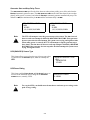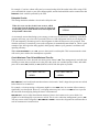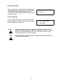
1
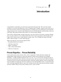
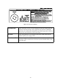
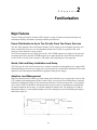
User Manual
Universal Transfer Switch
UTS6, UTS6BI and UTS10BI
.
Entire contents copyright © 2007 American Power Conversion Corporation. All rights
reserved. No part of this publication may be produced, transmitted, transcribed, stored in a
retrieval system, or translated into any language or computer language, in any form or by
any means, electronic, mechanical, magnetic, optical, chemical, manual, or otherwise without the prior written permission of American Power Conversion Corporation.
APC, the APC logo, and Trademark Names are trademarks of American Power
Conversion Corporation.
All other trademarks, product names, and corporate names are the property of their
respective owners, and are used for informational purposes only.
This manual is subject to change without notice.
FCC Compliance Information
These devices comply with Part 15 of the Federal Communications Compliance (FCC)
rules. Operation is subject to the following two conditions:
(1) These devices must not cause harmful interference, and
(2) These devices must accept any interference received, including interference that
may cause undesired operation.
As required, the bottom of this equipment contains, among other information, the Registration Number and Ringer Equivalence Number (REN) for this equipment. If requested, this
information must be provided to the telephone company.
Address:
American Power Conversion
132 Fairgrounds Road
West Kingston, RI 02892 USA
Email Support:
www.apc.com/support/
APC Toll-free
Technical Support:
1-800-555-2725
Contents
Page
About This Manual
Intended Audience
Revision Information
Important Safety Information
Safety Symbols
Important Safety Tips
Conventions and Typefaces Used
Protect Your Investment
References
Frequently Used Acronyms
iii
iii
iii
iii
iii
iv
iv
v
v
vi
Chapter 1 - Introduction
Proven Expertise... Proven Reliability
APC’s Universal Transfer Switches
Safety Precautions
Unit Power
Supporting 240V Circuits
Supporting 120V Circuits
Features Summary
UTS Controls and Indicators
UTS Power Connectors
1-1
1-1
1-2
1-2
1-3
1-3
1-3
1-4
1-4
1-4
Chapter 2 - Familiarization
Major Features
Power Distribution to Up to Ten Circuits From Two Power Sources
Quick, Safe and Easy Installation and Setup
Adaptive Load Management
Ability to Transfer Select Loads Between Backup Sources
Voltage Sensitivity
Time Management and Load Shedding
Security Mode
Bypass Mode
LCD Alphanumeric Display
Automatic Start/Stop Operation
2-1
2-1
2-1
2-1
2-1
2-2
2-2
2-2
2-2
2-2
2-3
2-3
Chapter 3 - Controls and Indicators
LCD, Push Buttons and LED Indicators
System Status
Circuit Status
Down Arrow/Up Arrow Buttons
Advanced Configuration and Setup
3-1
3-2
3-3
3-4
3-5
3-5
i
Contents
Page
Appendix A - Advanced Configuration
Advanced Configuration and Setup
System Configuration and Setup
Bypass Mode
Load Shedding
Voltage Sensitivity
Time Management
Reset Energy Meter
System Test
GEN Source Type
Generator Power Rating
Generator Surge Overload Time
Generator Start Mode
Generator Start and Stop Relay Positions
Generator Start and Stop Delay Times
UPS (BACKUP2) Source Type
UPS Power Rating
UPS Surge Overload Time
Reset to Factory Default
Circuits Configuration and Setup
Circuit Setup
Circuit Load Types
Circuit Source
Delayable Circuits
Circuit Maximum Time Off and Minimum Time On
Circuit Security Mode
Circuit Amp Rating
Appendix B - Troubleshooting
Troubleshooting Problems
While operating on utility power, some of the loads keep shutting off
While operating on backup power, some of the loads keep shutting off
While operating on backup power, the generator’s breaker keeps tripping
While operating on backup power, the UPS keeps shutting off
UPS remains on battery with the generator running
Circuit fault (no power on a circuit)
Loads on Circuit 1 cannot be powered by the UPS
ii
A-1
A-1
A-1
A-1
A-2
A-2
A-3
A-3
A-3
A-3
A-3
A-4
A-4
A-5
A-6
A-6
A-6
A-7
A-7
A-7
A-7
A-8
A-8
A-9
A-9
A-10
A-10
B-1
B-1
B-1
B-2
B-2
B-2
B-2
B-2
B-2
About This Manual
Intended Audience
This manual provides information for those persons responsible for set up, configuration and
operation of the UTS6, UTS6BI and UTS10BI Universal Transfer Switches (UTSs). Information
concerning troubleshooting common problems, and how to contact APC Technical Support
and/or Customer Service is also provided.
This manual is part of a documentation set that also includes the Universal Transfer Switch Site
Preparation and Installation Guide (Document No. 990-2992A), and the Universal Transfer
Switch Quick Install Guide (Document No. 990-3061A).
Revision Information
This is the initial release of this manual.
Important Safety Information
It is very important that you read the information contained in this section concerning product
safety, and that you understand the importance of the safety symbols that appear on the product,
and in this manual.
Safety Symbols
The safety symbols that appear on the unit, and in appropriate parts of this manual are shown and
described below.
Message: The hazardous voltage symbol is used to reduce the risk of electrical shock. Do not
remove the cover; this unit is to be serviced only by APC trained or qualified personnel.
WARNING
!
Message: The WARNING symbol provides information about procedures that, if not performed
exactly as stated, may result in injury or death.
Caution:
!
Message: The Caution symbol provides information about a procedure that, if not performed
exactly as stated, may result in equipment damage.
Note
!
Message: The Note symbol alerts the user to important operating and maintenance (service)
instructions, and other information in this manual that is essential to highlight.
iii
Important Safety Tips
The following are important safety tips that must be read and understood prior to installing or
operating a UTS6, UTS6BI or UTS10BI Universal Transfer Switch.
1. Read this manual - Read all of the safety and operating instructions before installing and
operating this device.
2. Keep this manual - Keep this manual, and all safety information that came with the device.
3. Warnings - Comply with all warnings presented in this manual, and on the device.
4. Follow Instructions - Follow all instructions for operating and using this device.
5. Water and Moisture - Do not use this product near any source of water, or in any environment where the relative humidity may exceed 95% (non-condensing).
6. Power - Ensure this device is connected to a properly grounded AC power source.
7. Power Cord - Ensure power cords are routed in a manner that will ensure they are not
pinched, frayed, or stepped on.
8. Overloading - Do not overload the load center where this device is connected, and do not
overload this device. Ensure the total load to this device does not exceed the value listed in
Appendix A - Specifications of the Universal Transfer Switch Site Preparation and Installation Guide (Document No. 990-2992).
9. Servicing - This device does not contain any user-serviceable components. Removing the
cover from this device by unqualified personnel may present a shock hazard and/or void the
warranty.
10. Damage Requiring Service - If any damage occurs to this device, disconnect the main
breaker, and notify your electrician, and/or APC Technical Support or Customer Service.
11. Replacement Parts - None of the components in this device can or should be removed or
replaced unless it is done by qualified service personnel.
12. Periodic Inspection - Inspect the line cords to ensure they are fully inserted, or attached.
13. Generator Usage - Never use a generator indoors, it could result in asphyxiation or death.
Caution
!
Stop using this device immediately, and have it inspected and serviced by APC if:
- The conduit or receptacles have been damaged.
- Objects have fallen into, or liquid has spilled into the unit.
- The unit has been exposed to rain, or other liquids.
- The unit does not operate properly.
- The unit has been dropped or damaged in any way.
Conventions and Typefaces Used
This manual uses the conventions and symbols described in the bullets that follow. The various
fonts apply to both general text, and text that appears in displays.
• Italics introduces or defines new or important terms, for example:
The LCD display provides informational messages...
• Bold is used for extra emphasis, and is often used to indicate a screen, menu, field, mode or key
name; for example:
DO NOT remove the cover from the unit. The System Setup button...
• Courier New indicates text that is typed into a location on a screen or Web browser, or in
response to a prompt.
iv
Protect Your Investment
Please take a few minutes to fill out and mail the enclosed Warranty Registration Card, or complete the
online form at: www.apc.com to ensure you receive all the benefits and protection that accompany your
purchase.
Note: Under California law, failure to register your purchase may not exclude you from provisions
of the Warranty and Equipment Protection Policy. The benefits of warranty registration are
outlined in the following subparagraphs.
Registration - Registering your purchase now guarantees that you will receive all the information and
special offers you qualify for as the owner of this product.
Verification - Registering your purchase confirms your right to maximum protection under the
Warranty terms and conditions.
Confirmation - Registering your purchase now provides you with a way to confirm yourself as the
owner of the product in the event of fire, theft or loss.
Reference Documents
There are several APC documents contained in the following table that are applicable to the
UTS6, UTS6BI and UTS10BI Universal Transfer Switches.
Reference Documents
Document Title
Web Site
Universal Transfer Switch Quick Install Guide
http://www.apc.com/support/
Universal Transfer Switch User Manual
http://www.apc.com/support/
v
Frequently Used Acronyms
A
AC
AFCI
ALMTM
APC
AVR
CSA
DC
EMI
FCC
GFCI
GND
HP
Hz
KwH
LCD
LED
LPG
MOV
NEC
NEMA
NG
RFI
SOHO
TVSS
UL
UPS
UTS
VA
VAC or Vac
ampere
alternating current
arc-fault circuit interrupter
adaptive load management
American Power Conversion
automatic voltage regulation
Canadian Standards Association
direct current
electromagnetic interference
Federal Communications Commission
ground-fault circuit interrupter
ground
horse power
Hertz
kilowatt hour
liquid crystal display
light-emitting diode
liquefied petroleum gas
metal oxide varistor
National Electrical Code
National Electrical Manufacturers’ Association
natural gas
radio frequency interference
small or home office
transient voltage surge suppression
Underwriters’ Laboratories
uninterruptible power supply
universal transfer switch
Volt Amps
Volts AC
vi
C h a p t e r
1
Introduction
Congratulations on purchasing your APC Universal Transfer Switch (UTS). Three universal transfer
switches are covered in this manual, the UTS6, UTS6BI and the UTS10BI. A transfer switch is the key to
safe and convenient operation of portable generators for standby power. By isolating those circuits that are
using generator power, a transfer switch eliminates the risk of backfeeding the electrical utility, which can
cause injury and possibly death to utility workers, as well as property damage.
These units are fully automatic, and provide power to up to ten circuits in your home or business. Backup
power is derived from one or two independent backup sources such as a generator, uninterruptible power
supply (UPS), solar inverter, or other alternative energy source. The UTS10BI, the largest of the three
units, is shown in Figure 1-1 on the following page.
Major topics that are covered in this chapter include:
• Recommended Safety Precautions
• Unit Power Capacities
• Major UTS Features
• UTS Controls and Indicators
• UTS Power Connectors
Proven Expertise… Proven Reliability
From corporate data centers to home offices, APC is regarded as a leading innovator, designer and
manufacturer of high-quality power protection solutions. With its proven reputation for Legendary
ReliabilityTM, leading companies depend on APC every day, 24 x 7 x 365 to protect and support many of
the most critical networks in the world. Over the last 20 years, APC has been a pioneer in the development
of innovative power protection technologies that have resulted in countless industry awards, design patents
and an installed base numbering in the tens of millions of units. Multiple R&D centers, in conjunction with
APC-owned and controlled factories, ensure APC solutions are the safest, most advanced and most reliable
products available. When you buy APC products you buy “peace of mind”.
1-1
Figure 1-1. UTS10BI Universal Transfer Switch
APC’s Universal Transfer Switches
APC’s UTS6, UTS6BI and UTS10BI Universal Transfer Switches (UTSs) are designed to supply
power to circuits in a home office or small office from up to two independent backup sources such
as a generator, uninterruptible power supply (UPS), solar inverters, or other alternative energy
sources. In most regions of the United States and Canada national and local electrical codes, and
the electric utilities require a transfer switch to connect a generator to your home or small office
electrical wiring.
The APC UTSs provide a safe and convenient way to connect a generator, and other backup
power sources, to supply power to circuits used by essential home appliances, and computing and
entertainment equipment during power outages. When a UPS is included clean, uninterrupted
power is provided. The UTSs also support hardwired loads such as furnaces, sump pumps, and
similar devices.
1-2
Safety Precautions
Ensure that you read and understand all of the safety information contained in “About This Manual”, in the
front of this manual. If you have any questions concerning any of the safety information, or if you are
concerned that your home or office may not be properly wired for this equipment, contact a qualified and
licensed electrician, and APC Technical Support.
Unit Power
The UTS6 and UTS6BI are rated for 20 A (continuous), and the UTS10BI is rated for 30 A (continuous)
while on BACKUP1 (generator). However, they are designed to support component inrush currents that
are much higher than their continuous power ratings. The UTS6BI and UTS10BI models are designed to
operate with a 120V/240V load. The UTS6 is only intended for 120V circuits and loads. Also note that
BACKUP2 (UPS) is 15 A or less.
Note
!
There is also a “hard wiring” option (Part No. UTSHW) to support up to 50 A
generators.
Supporting 240V Circuits
An example of a 240V application would be a well pump. Most well pumps with 1/4 horse power (HP)
motors or greater require 240V, 2-pole (also called “split phase”) power. Models UTS6BI and UTS10BI
are designed to operate with both 120V and 240V loads. However, you must follow these 240V rules:
• Only one 240V circuit can be backed up through the UTS. However, multiple 240V loads can be wired
to that 240 V circuit if required. Consult with a licensed electrician and APC Technical Support for
additional information.
• A 240V circuit will use two UTS circuits. These are Circuits 9 and 10 for the UTS10BI, and Circuits 5
and 6 for the UTS6BI.
• The 240V circuits are only powered from the Backup1 (generator) source.
Supporting 120V Circuits
Most of the circuits and loads in your home or office will be 120V, single pole. Other than the 240V circuit,
all other UPS circuits are 120V circuits. The number of 120V circuits supported by each of the UTS
models are summarized below.
Model
Number of
120V Circuits
Circuits Used for
240V
UTS6BI
Four (1 - 4)
5 and 6
UTS6
Six (1 - 6)
N/A
Eight (1 - 8)
9 and 10
UTS10BI
The following rules must be observed for 120V circuits and loads:
• The 120V circuits should be balanced between Phase 1 and Phase 2 of the incoming generator power for
safe operation, and to ensure optimal backup generator operation.
• If you use a second backup source (for example, a UPS) please note that Circuit1, which also powers the
convenience outlet for the UPS, only works with generator (GEN) as the backup power source. All other
120V circuits can be backed up by the UPS source.
1-3
Features Summary
The Model UTS6, UTS6BI and UTS10BI Universal Transfer Switches include the following
major features:
• A fully automatic transfer switch that provides power for up to ten circuits from one or two independent
backup sources
• Quick, easy and safe configuration, installation and setup
• Certified to UL 1008 Transfer Switch Equipment standard
• UPS backup for true uninterrupted operation
• Ability to transfer select loads between backup sources (generator and UPS) to provide maximum power
availability and runtime
• Adaptive load management (ALM) prevents momentary surges and overloads from stalling the
generator, and helps maximize generator operating efficiency
• Over voltage and under voltage protection safeguard electrical equipment
• LCD displays status messages including voltage, current and power values, and energy usage levels
• Semiautomatic operation with manual start generators by switching to generator power as soon as it is
detected
• Fully automatic operation with remote controlled auto start/stop generators
• Support for hardwired loads such as well pumps, sump pumps and furnace blower motors
• Security mode timer automatically controls lights, and appliances to deter burglaries
• Designed for 240V, split phase, 20A or 30A for Backup Source1, and up to 50 A with hard wire option
• Designed for 120V, single phase, 15A for Backup Source2
• Time management, in concert with load shedding, ensures loads get the power they need
• Bypass mode for service and maintenance
For more detailed information reference Chapter 2 in this manual.
UTS Controls and Indicators
The front panel controls and indicators for the UTS6, UTS6BI and the UTS10BI are located on the top of
the UTS, and are virtually the same, except for the number of Circuit Status LED indicators. The UTS6
and UTS6BI have six, and the UTS10BI has ten Circuit Status LEDs. A 2-line, 20 characters per line
liquid crystal display (LCD) is provided, as well as pushbutton controls, and three Source Status LED
indicators. The UTS controls and indicators are discussed in greater detail in LCD, Pushbuttons and LED
Indicators in Chapter 3.
UTS Power Connectors
The power connectors are located on the lower half of the UTS front panel, as shown in Figure 1-2, and
described in the table that follows.
1-4
Figure 1-2. UTS Power Connectors
Generator Inlet
This is the male L14-20 or L14-30 connector for the power input cable that
connects from the generator, and is supplied by the customer. Additional
generator power input cable information is provided in Appendix A of the Site
Preparation and Installation Guide (990-2992A).
UPS Inlet
This is the female IEC 320 connector for the power input cable from the
uninterruptible power supply (UPS).
Convenience Outlet
This is a standard female NEMA 5-15, 120 Volt convenience outlet for
powering a UPS, or other device. It derives its power from the utility, or the
generator input.
1-5
1-6
C h a p t e r
2
Familiarization
Major Features
The APC Universal Transfer Switches (UTSs) include a variety of features and options that provide
maximum flexibility, and enhance operating reliability and efficiency.
Power Distribution to Up to Ten Circuits From Two Power Sources
The APC fully automatic Universal Transfer Switches (UTSs) supply power to multiple circuits in your
home or small office from one or two independent backup sources, such as a generator, UPS, solar
inverters or other alternative energy sources.
The UTS6 can support up to six single-pole circuits. The UTS6BI supports four single-pole circuits and
one double-pole circuit, and the UTS10BI supports up to eight single-pole circuits and one double-pole
circuit. Hard wired loads such as furnaces, well pumps, and sump pumps are also supported.
Quick, Safe and Easy Installation and Setup
The UTSs provide a safe and convenient way to connect a generator, uninterruptible power supply (UPS)
and other backup power sources to supply power to circuits used by essential home automation devices and
appliances, and computing and entertainment equipment during power outages.
Adaptive Load Management
With conventional transfer switches you must manage loads manually to prevent generator overload. The
UTS’s adaptive load management (ALMTM) feature allows you to power more loads during an extended
blackout by intelligently turning off circuits that may otherwise overload your generator, or your backup
power source (UPS). Loads that are disconnected due to power surges or overloading are automatically
reconnected when the power surge, or overload condition no longer exists. The principles of ALM are
illustrated in Figure 2-1, and explained further in the Time Management and Load Shedding description
that follows Figure 2-1.
Figure 2-1. Power Characteristics With ALM and Without ALM
2-1
Ability to Transfer Select Loads Between Backup Sources
When the UTS is connected to both a generator and UPS, it can automatically transfer select loads between
the backup sources.This helps minimize power interruptions to the loads due to Generator or UPS
overloading.
Voltage Sensitivity
This feature allows you to determine how the UTS reacts to momentary power fluctuations. Sensitivity can
be set to LOW, MEDIUM, or HIGH. The factory default is MEDIUM, which is suitable for most situations.
The HIGH setting is only recommended when your loads are very sensitive to small, brief power
fluctuations. The LOW setting is most useful for when you have frequent power fluctuations that do not
require intervention by the UTS.
Time Management and Load Shedding
Time management, in concert with load shedding, ensure that loads get the power they need. For load
shedding (load dropping), the UTS incorporates a patent-pending method called Adaptive Load
Management (ALMTM) that increases the capabilities of your backup sources. This method causes loads to
be dropped when the generator is in danger of an overload, and it reconnects the loads when sufficient
power is available. Thus, the most suitable individual loads are selected to shed (drop) or reconnect as
required, to minimize disruptions to your total load. When ALM is turned on over an extended period of
time (greater than 30 minutes), it can increase the operating efficiency of a typical generator by about 20%.
Also refer to the Adaptive Load Management (ALM) description.
Security Mode
Security mode is used when you go on vacation, or on an overnight trip. When SECURITY mode is set to
ON, the UTS automatically cycles power to circuits at the rate of two hours on, and two hours off. It is also
called "vacation mode".
Bypass Mode
In bypass mode, all circuits are powered by the primary utility power source only. Backup sources are not
used to power the loads, regardless of the status of the primary utility power source. However, overload
protection is provided. Bypass mode is covered in greater detail in Chapter 3.
LCD Alphanumeric Display
The liquid crystal display (LCD) is a two line alphanumeric display with 20 characters per line. During
initial setup and configuration, the LCD displays the particular setting or value that is to be entered or
changed. During regular operations, the LCD is used with the various LED indicators, and push buttons to
provide UTS informational status messages, warnings, and to perform required actions.
Automatic Start/Stop Operation
This feature is available for automatic start/stop generators, and provides the ability to start and stop the
generator remotely, with no human intervention. To operate in automatic mode, the generator requires
electric remote start/stop buttons, and an automatic choke. If you will be using an automatic start/stop
generator, you must order APC’s optional UTS Generator Hard Wiring Interface Kit (UTSHW), and UTS
Automatic Remote Start/Stop Kit (UTSREM) when you order your UTS.
2-2
C h a p t e r
3
Controls and Indicators
This chapter describes and illustrates the controls and indicators that are used to setup, configure
and operate the UTS6, UTS6BI and UTS10BI Universal Transfer Switches (UTSs). The controls
are six push buttons, which are used with LED indicators, and text messages displayed on a liquid
crystal display (LCD), as shown in Figure 3-1. The LCD displays two lines of text, 20 characters
per line.
The various status and informational messages, and system operations that are used during
installation, initial power on and setup are also discussed in Chapter 3 of the Universal Transfer
Switch Site Preparation and Installation Guide (Document No. 990-2992A). Another site
preparation and installation related document is the UTS Quick Install Guide (Document No.
990-3061A).
This chapter discusses the following major topics:
•
•
•
•
LCD, push buttons and LED indicators
System Status
Circuit Status
Advanced Configuration
3-1
LCD, Push Buttons and LED Indicators
The alphanumeric liquid crystal display (LCD), push buttons, and LED indicators are located on
the top half of the front panel. They are shown in Figure 3-1, and described in the table below.
7
2
3
8
4
1
5
6
Figure 3-1. UTS Controls and Indicators
UTS Controls and Indicators Summary
Control or Indicator
Description
1
LCD alphanumeric display
The green liquid crystal display (LCD) is a 2-line display with 20 characters
per line that is used to show UTS status, and any important warnings or
informational messages. During configuration and setup, the LCD also
displays the value or setting that is being entered and/or changed.
2
System Status button
This button is used to cycle the UTS through the various system options or
settings, which are displayed on the LCD.
3
System Setup button
This button is used to configure or change the UTS system settings.
4
Circuit Status button
This button is used to cycle the UTS through the various circuit options or
settings, which are displayed on the LCD.
5
Circuit Setup button
This button is used to configure or change individual UTS circuit settings.
6
Down/Up Arrow buttons
The Down and Up arrow buttons are used to step through the various options
during configuration and setup, and to scroll between the various status and
informational displays.
7
Source Indicators (Green)
The three green LED indicators on the front panel under Source show the
status of the power sources, which include: Utility, Generator, and UPS.
When one of these LEDs is ON (lit) it indicates that particular power source
is normal and available.
When a LED is OFF (not lit) it indicates that the source is not available to
supply power to any of the loads on the circuit.
When a LED is flashing it indicates that a fault or abnormal condition exists
that should be corrected.
3-2
8
Circuit Indicators (Red)
Depending on the UTS model there can be up to ten red LED indicators
located on the front panel under Circuit that show the status of the circuits
being backed up by the UTS.
When one of the LEDs is ON (lit) it indicates that circuit is receiving power
from one of the power sources.
When a LED is OFF (not lit) it indicates that circuit is not receiving power.
When a LED is flashing OFF and ON it indicates that a fault or abnormal
condition exists that should be corrected.
System Status
The UTS system status, and the status of up to three power sources can be viewed by pressing the
System Status button. The messages are displayed in sequential order beginning below, with a
brief description of each message.
This message contains the AC input voltages from the
UTILITY via the main load center for PHASE1 and
PHASE2.
UTILITY PHASE1: 120V
UTILITY PHASE2: 120V
This message shows the SYSTEM LOAD (total power)
that is being drawn through the UTS, which is further
divided into the power drawn by each phase - PH1 and
PH2. This information is especially useful for verifying
that the phases are balanced.
SYSTEM LOAD: 2400W
PH1: 1050W PH2: 1350W
This message displays the BACKUP1 source voltages
for GEN PHASE1 and GEN PHASE2.
This message shows the BACKUP1 source power
outputs for GEN PHASE1 and GEN PHASE2.
This message includes the UPS VOLTAGE and UPS
LOAD (power) for the BACKUP2 source (normally the
UPS).
3-3
GEN PHASE1: 117V
GEN PHASE2: 118V
GEN PHASE1: 480W
GEN PHASE2: 750W
UPS VOLTAGE: 120V
UPS LOAD: 200W
This message contains the MODEL# (model number)
and SN# (serial number) of your UTS.
MODEL#: UTS10BI
SN#: JB06008004272
This message provides the firmware version (FW VER)
that is used in your UTS.
UTS FW VER: 1
UI FW VER: 1
This message shows the date your UTS was
manufactured (MFG DATE).
MFG DATE:07/23/2006
Circuit Status
Pressing the Circuit Status button allows you to display additional details about each of the
circuits. An example is provided below:
In this example, CK1SRC (Circuit 1 Source) indicates
the power source plus the status of Circuit1: 1 Amp, 2.35
kWh, and 120 Watts.
CK2SRC (Circuit 2 Source) would indicate the power
source, and would contain status information similar to
that shown for CK1SRC above.
CK1SRC:UTILITY AMP:1
KWH:2.35 WATTS:120
The following table is a summary of the types of source states, and power status informational
messages that are displayed on the LCD.
Summary of Source States and Informational Messages
Source(s)
Description
UTILITY
When this is displayed it indicates that power is supplied from the normal utility source.
STANDBY
Indicates that the circuit is in standby mode, and is not receiving power.
GEN
This indicates the circuit is powered by a generator.
UPS
This indicates the circuit is powered by a UPS.
BYPASS
This indicates the circuit is being bypassed to the utility power. When the UTS is in the
bypass state (which applies to the whole system) the UTS always supplies power directly
from the utility to all the circuits, regardless of the power’s quality or condition.
FAULT
This indicates the circuit has a fault, and additional messages are used to display more
specific fault information.
3-4
SECURITY
This indicates the circuit is in security mode. This is primarily used for indoor and
outdoor lighting circuits. This mode of operation is used when you are away from home,
such as on vacation. In this mode the circuit is supplied power for two hours, goes off
for two hours, is again supplied power for two hours, and so on.
Status
AMPs
This is the current in Amperes for a circuit.
KWH
This is the energy consumed by the load(s) on a circuit since the energy meter was last
reset. Kilowatt hours are used, which is also how the electric company bills for
electricity. You can use this information to analyze and manage your energy
consumption.
WATTs
Watts are used to indicate the total power consumed by the loads on a circuit.
Down Arrow/Up Arrow Buttons
The Down arrow and Up arrow buttons, shown in Figure 3-1, are used to step through the various
options during configuration and setup, and to scroll between the various status and informational
messages.
Advanced Configuration and Setup
Advanced configuration and setup is covered in Appendix A, which contains two major
procedures:
• System Configuration and Setup
• Circuits Configuration and Setup.
3-5
3-6
A p p e n d i x
A d v a n c e d
A
C o n f i g u r a t i o n
Advanced Configuration and Setup
Advanced configuration and setup consists of two major tasks, system configuration and setup, and circuits
configuration and setup.
System Configuration and Setup
Press the SYSTEM SETUP button to enter system setup mode. The LCD setup messages will appear in the
order they are described in this section. The Up Arrow and Down Arrow buttons are used to move between
messages, and to change values.
Note
!
The settings or values will change immediately after a Down Arrow or Up Arrow
push button is pressed.
Bypass Mode
This mode can be disabled by selecting NO, or enabled by selecting YES. The factory default is NO.
In BYPASS MODE, all circuits are powered by the utility
power source. Backup sources are not used to power the
loads regardless of the status of the primary utility power
source.
Note
!
BYPASS MODE:
NO/YES
Changing Bypass settings while on Utility will cause all loads to be momentarily
disconnected.
Other protections such as over voltage and under voltage protection are not
available in Bypass mode. However, overload protection is provided.
Press the System Setup button to display the next message.
A-1
Load Shedding
Load shedding can be turned ON or OFF, as shown in this
example, to shed (drop) a load or loads. The factory
default setting is ON.
LOAD SHEDDING:
ON/OFF
The UTS includes an algorithm (software) for intelligent load management, defined by APC as adaptive
load management (ALM), that maximizes the capabilities of backup sources. The algorithm sheds (drops)
loads when the generator is in danger of being overloaded, and reconnects them when adequate power is
available. It also adaptively selects the most suitable loads to drop or reconnect at any given time, which
minimizes load disruptions.
Note
!
When ALM is on it can increase the perceived power output of a typical generator
by about 20%. This allows you to add more loads without overloading or stalling
the generator.
When load shedding is turned off, the UTS will not drop any loads. During overload conditions the
generator may stop running, a circuit breaker may trip, or the loads may momentarily experience severe
under voltage conditions.
Press the System Setup button to display the next message.
Voltage Sensitivity
The level the voltage sensitivity is set to (LOW, MEDIUM or
HIGH) determines how the UTS reacts to momentary power
fluctuations. The factory default setting is MEDIUM, which is
suitable for most situations.
VOLTAGE SENSITIVITY:
LOW/MEDIUM/HIGH
It is recommended that you only use HIGH when the loads are very sensitive to small, brief power
fluctuations. LOW can be used if you have frequent power fluctuations that do not require the attention of
the UTS. More detailed specifications are provided in Appendix A of the Universal Transfer Switch Site
Preparation and Installation Guide (Document No. 990-2992A).
Press the System Setup button to display the next message.
Time Management
Time management is used with load shedding to ensure that
your loads receive the power they need over extended periods
of time.
When time management is set to OFF, the MAXIMUM OFF
time and MINIMUM ON time settings are disabled.
TIME MANAGEMENT:
ON/OFF
The two key time management components are MAXIMUM OFF time, and MINIMUM ON time. They can be
individually set for each circuit. When this feature is ON, time management works in the background to
ensure that each circuit is not shed (power is not removed) for more than the MAXIMUM OFF time.
Conversely, the MINIMUM ON time ensures that the circuit will be powered for at least the minimum time
setting before it can be shed (dropped) again. More detailed information is provided later in this chapter in
the Delayable Circuits description.
A-2
Note
MAXIMUM OFF
and MINIMUM ON times are set separately for each circuit.
!
Press the System Setup button to display the next message.
Reset Energy Meter
This feature allows you to determine the total electric energy
that is being consumed by your loads in kilowatt hours (kWh).
When it is reset, the kWh counter for each circuit resets to 0,
and counts from that point forward.
Press the System Setup button to display the next message.
RESET ENERGY METER:
YES/NO
System Test
System test can be set to NO or YES. Setting it to YES initiates
system test, which checks UTS basic operation and related
components.
Press the System Setup button to display the next message.
SYSTEM TEST:
NO/YES
GEN Source Type
This feature allows you to select the type of power source that
is connected to the UTS Generator Inlet.
The default is GENERATOR.
Press the System Setup button to display the next message.
BACKUP1 SOURCE TYPE
GENERATOR/UPS/OTHER
Generator Power Rating
This display, and the Down Arrow and Up Arrow buttons are
used to set the maximum power rating for the generator.
Press the System Setup button to display the next message.
Note
!
GEN POWER RATING:
0-12000W
For typical generators you should enter the generator’s maximum continuous
power rating, not its peak or surge rating.
For example, a typical standby generator designed for the home, and rated at 5000 Watts peak/surge, may
only have a continuous rating of 4000 Watts. The UTS intelligent adaptive load management (ALM)
algorithm tries to optimize the average power output of the generator, and the continuous rating is the most
appropriate to use.
A-3
Note
!
A value can be entered faster by pressing the Up Arrow or Down Arrow key, and
holding it down until the desired value is displayed. Holding the button down
causes the numbers to advance much faster. The display moves by 5 Watt
increments, then 10 Watt increments, and then by 100 Watt increments. When you
release the button it causes the incrementing speed to be reset, and it reverts back
to 5 Watt increments.
Press the System Setup button to advance to the next displayed message.
Generator Surge Overload Time
This value is used to determine the response speed of the
ALM algorithm. When the power output from the BACKUP1
SOURCE surge exceeds the power rating (which was set
earlier in this section) for the specified GEN SRGE OVERLD
TIME (a value in the [0 - 600] SEC range), then load shedding
will be activated.
Note
!
GEN SRGE OVERLD TIME
[0-600] SEC
If you reduce the surge overload time it reduces the likelihood that the generator
will be overloaded, but it increases the chance load shedding will occur.
If you increase the surge overload time it increases the likelihood that the generator
will be overloaded, but decreases the chance that load shedding will occur.
For “inverter generators”, set the time to zero (0).
Press the System Setup button to advance to the next displayed message.
Generator Start Mode
This display is used to select either MANUAL, if you have a
conventional generator that is started manually, or AUTO,
which is selected if you want to take advantage of the UTS
remote automatic start/stop feature. The default is MANUAL.
The next message asks you if the generator (GEN) is
OUTDOORS. APC’s UTS Generator Hard Wiring Interface
Kit (UTSHW) is provided to allow the generator to be plugged
in outside of the house.
A-4
GEN START AUTO/MAN:
MANUAL
CONFIRM GEN OUTDOORS:
NO
YES
Note
!
Warning
!
The automatic start/stop generator must have an automatic choke, and must be
capable of being started and stopped automatically from a remote location. Refer
to your generator user’s manual; if you are still unsure, contact the generator
manufacturer.
Also, to take full advantage of the automatic start/stop capability, we strongly
recommend that you use a UPS as the BACKUP2 source. If you do not have a UPS,
you cannot control the delays or relay positions of the start/stop relays if a power
failure should occur, and proper operation during a power outage cannot be
guaranteed.
Operating a gas generator inside a building or any other enclosed area may result
in asphyxiation or death from breathing carbon monoxide. Locate the generator
outdoors away from doors and windows. Ensure the generator has 3 to 4 feet of
spacing on all sides, including above the generator. Generators need an unlimited
supply of fresh air for proper cooling during operation. If the generator uses
gasoline, ventilation is critical and fuel must be stored in containers approved for
gasoline storage. Ensure that the generator is kept dry and is always operated on a
solid, level surface.
If you select MANUAL skip the next four sections. If you select AUTO then continue with the next four
sections by pressing the Down Arrow key.
Note
!
The UTS Automatic Remote Start/Stop Kit (UTS REM) is required for automatic
generator start/stop operation.
Press the System Setup button to advance to the GEN START RELAY POS, and GEN STOP RELAY POS
displays.
Generator Start and Stop Relay Positions
The generator is automatically started by closing a set of relay contacts. These settings are used to ensure
proper automatic start/stop operation based on the specific operating requirements of your generator. The
default is NORMALLY OPEN.
Caution
!
Thoroughly review your generator user’s manual for the manufacturer’s
recommended installation guidelines, and contact your electrician to ensure it is
installed properly. APC provides a UTS Generator Hard Wiring Interfacing Kit
(UTSHW) that can be connected to the generators of manufacturers with whom
APC has jointly performed tests. A UTS Automatic Remote Start/Stop Kit
(UTSREM) is also available from APC to connect to a generator capable of remote,
automatic start/stop operation.
GEN START RELAYPOS:
GEN STOP RELAY POS:
NORMALLY OPEN/CLOSED
NORMALLY OPEN/CLOSED
Press the System Setup button to advance to the GEN START DLY TIME and GEN STOP DLY TIME displays.
A-5
Generator Start and Stop Delay Times
The GEN START DLY TIME specifies the delay between when primary utility power fails, and when the
Backup1 automatic generator starts. The GEN STOP DLY TIME sets the time that elapses between when
primary utility power is restored, and when the Backup1 automatic generator automatically stops. The
default is 5 MIN, the minimum delay is 30 SEC and the maximum delay is 60 MIN.
GEN START DLY TIME:
5 MIN
30 SEC
1,2,5,10,20,30,60 MIN
Note
!
GEN STOP DLY TIME:
5 MIN
30 SEC
1,2,5,10,20,30,60 MIN
The UTS will attempt to start the generator up to three times. The time interval
between each start attempt is defined by GEN START DLY TIME. If the generator
does not start after the third attempt, the system ceases trying, and signals a fault.
When utility power is restored, the UTS will attempt to stop the generator up to
three times. The time interval between each stop attempt is defined by GEN STOP
DLY TIME. If the generator does not stop after the third attempt, the system ceases
trying, and signals a fault.
UPS (BACKUP2) Source Type
This feature allows you to select the type of power source that
is connected to the BACKUP2 input, which is normally the
UPS.
BACKUP2 SOURCE TYPE:
UPS
GENERATOR
OTHER
UPS Power Rating
This feature and the Down Arrow and Up Arrow buttons are
used to set the maximum power rating for the BACKUP2
POWER source, normally a UPS.
Note
!
BACKUP2 POWER:
0-1800W
For a typical UPS you should enter the maximum continuous power rating, not its
peak or surge rating.
A-6
UPS Surge Overload Time
This value is used to determine the response speed of the
ALM algorithm. When the power output from the UPS source
surge exceeds the power rating (set earlier in this section) for
the specified UPS SRGE OVERLD TIME (a value in the
[0-60] SEC range), then load shedding will be activated.
Load shedding occurs when the rated output power of the
UPS is exceeded for longer than the SRGE OVERLD TIME.
Note
!
UPS SRGE OVERLD TIME
[0-60] SEC
If you reduce the surge overload time it reduces the likelihood that the UPS will be
overloaded, but it increases the chance that load shedding will occur.
If you increase the surge overload time it increases the likelihood that the UPS will
be overloaded, but decreases the chance that load shedding will occur.
Reset to Factory Default
Select YES to reset all configurable parameters to the factory
default. Selecting YES also restarts the UTS Setup Wizard,
which is described in Initial Setup in the Universal Transfer
Switch Site Preparation and Installation Guide (Document
No. 990-2992A).
RESET TO DEFAULT
NO/YES
Circuits Configuration and Setup
Press the Circuit Setup button to enter Circuit Setup mode. When the circuit setup messages are displayed
they appear in the same order as they are listed in this section.
Note
!
Use the Up Arrow and Down Arrow buttons to move between displays, and to
change settings. Also, note that settings change immediately as soon as the Up
Arrow or Down Arrow button is pressed.
Circuit Setup
Circuit setup begins with Circuit 1, and proceeds through all of the configuration settings for Circuit 1
before moving on to Circuit 2, the same is true for Circuit 2, then Circuit 3, and so on.
Note
!
To configure a particular circuit, use the Circuit Status button and change the
display to show the desired circuit (for example, CKT3), then press the Circuit
Setup button. The setup screen for that particular circuit will be displayed.
A-7
Circuit Load Types
Examples of the types of loads that may be connected to a circuit, and the labels that are typically found
beside the circuit breakers on a circuit breaker panel are summarized below.
• LIGHTS
• COMPUTER
• HOME THEATER
• GARAGE DOOR OPENER
• SUMP PUMP
• SPRINKLER SYSTEM
• SECURITY ALARM
• REFRIGERATOR
• FURNACE
• WELL PUMP
(or other motor-driven device, such as a blower or exhaust fan)
• FREEZER
• MICROWAVE OVEN
• AIR CONDITIONER
(use for other loads not listed above)
Once the load type is selected, the UTS automatically configures the remainder of the settings and values
so that they support your overall system requirements. However, you can continue to customize settings
and values as needed.
• OTHER1
Circuit Source
This setting determines which of the backup sources (GEN,
UPS or OTHER) will be used to power the circuit’s load.
Some possible choices are shown below.
CKT1 SOURCE
GEN/UPS/OTHER...
GEN – The load will only be backed up by the generator (GEN) during a power outage.
UPS – The load will only be backed up by the UPS during a power outage.
Note
!
This option is not available for Circuit1, or for 240V circuits (Circuits 9 and 10 for
UTS10BI, and Circuits 5 and 6 for UTS6BI).
EITHER – The load can be backed up by either type of power source during a power outage.
Note
!
This option is not available for Circuit1, or for 240V circuits (Circuits 9 and 10 for
UTS10BI, and Circuits 5 and 6 for UTS6BI).
NONE – The load will not be backed up by any of the power sources during a power outage.
UNINTERRUPTIBLE – The load is always backed up (even when using primary UTILITY power) by the
UPS power source. This selection is for using a UPS as the power source. When it is set for uninterruptible,
the power to the load will always flow through the UTS and UPS, taking full advantage of the power
protection, filtering, voltage regulation, and other UPS backup features provided by the UPS.
A-8
For example, if you have a home office and you want to backup all of the outlets in the office using a UPS,
you would make the circuit to your office uninterruptible, and the load and all the outlets connected to that
BACKUP2 circuit would be protected by the UPS.
Delayable Circuits
This setting determines whether a circuit can be delayed or not.
When it is set to YES the circuit is DELAYABLE, which
means that when the backup power source is about to be
overloaded, power to that circuit can be interrupted and
delayed until a later time.
CKT1 DELAYABLE
YES/NO
As an example, assume that during a power outage you turn on your microwave, which may overload the
generator and cause you to lose all of your loads. However, if the refrigerator load is set as delayable, the
UTS can temporarily disconnect power to the refrigerator to allow the microwave to be powered. Then
when the microwave is turned off, power to the refrigerator is automatically turned back on. This is a good
example of the ALM algorithm being applied, which greatly enhances your generator’s usefulness and
operating efficiency.
When CKT1 DELAYABLE is set to NO, power to that circuit is not delayable. This in turn means the circuit
will receive power with as few interruptions as possible.
Circuit Maximum Time Off and Minimum Time On
These parameters are active when the time management feature is ON. Time management is used with load
shedding to ensure that your loads receive the power they need over extended periods of time, and enable
power to be turned ON (enabled) or OFF (disabled) with as little disruption as possible.
CKT1 MAX TIME OFF:
CKT1 MIN TIME ON:
1-60MIN
1-60MIN
MAX TIME OFF is used to adjust the maximum time a circuit can be "shed" (dropped) to prevent an overload
before it has to be reconnected.
For example, a circuit powering a refrigerator might be set to 30MIN, since its contents will not warm up
significantly over that period. However, a well pump motor may have to be set to 5MIN or less to prevent
the water tank from emptying during the time it is disconnected.
MIN TIME ON is used to adjust the minimum amount of time a circuit must receive power before it is
eligible to be shed (dropped) to prevent an overload. This is active when time management is active (ON).
You may want to set the refrigerator’s MIN TIME ON to 45MIN to ensure the refrigerator has sufficient time to
cool its contents once it turns back on.
A-9
Circuit Security Mode
When security mode is enabled, the UTS automatically
cycles power to the circuit (two hours on, and two hours
off). This mode is for when you expect to be away
overnight, or for an extended period of time, such as when
you go on vacation.
CKT1 SECURITY MODE:
OFF/ON
Circuit Amp Rating
Use this feature to configure a circuit to have the same
ampere rating (15 A or 20 A) as its corresponding circuit
breaker located in the load center.
Caution
!
Note
CKT1 AMP RATING:
15/20 AMPS
Selecting an improper ampere (A) rating can violate the electrical code. For
example, selecting a rating greater than the circuit breaker rating is a violation.
This can result in “nuisance trips" where the circuit breaker or fuse “trips”
frequently due to an over current condition.
The circuit ampere (A) setting should be configured by your electrician during
initial setup and installation.
!
A-10
A p p e n d i x
B
T r o u b l e s h o o t i n g
This appendix describes causes and recommended solutions for possible UTS problems.
Note
!
Note
The LCD screen will display any faults or warning conditions that occur along with
informational messages. If you are ever in doubt as to what action to take, please
contact APC Technical Support:
Internet — www.apc.com/support/
Phone — 800-555-2725
In the following possible causes and recommended solutions local electrical codes
and the National Electrical Code (NEC) must be followed in all cases.
!
While operating on utility power, some of the loads keep shutting off
Possible Cause: One of the circuits may be in Security mode.
Solution: Check the circuits to ensure none of them are in Security mode.
Possible Cause: One of the circuits may be overloaded, as indicated on the LCD.
Solution: Reduce the load, or if necessary, have an electrician upgrade the circuit to 20A.
While operating on backup power, some of the loads keep shutting off
Possible Cause: Adaptive load management (ALM) may be active.
Solution: Ensure that the generator’s power rating is set correctly and is appropriately rated (under System
Configuration in Appendix B).
Possible Cause: A circuit that should not be shutting off is shutting off.
Solution: Change the circuit’s load type, or set CKT1 DELAYABLE to NO.
Solution: Disabling the ALM can also cause the generator to overload.
B-1
While operating on backup power, generator’s breaker keeps tripping
Possible Cause: The ALM is disabled.
Solution: Enable the ALM.
Possible Cause: Ensure the generator and/or UPS is rated appropriately (reference System Configuration
in Appendix B of the Universal Transfer Switch Site Preparation and Installation Guide).
Solution: If the generator is not rated correctly, the ALM will not be able to prevent generator overloads.
Lower the power ratings as needed, and reduce the Overload Delay Time.
While operating on backup power, UPS keeps shutting off
Possible Cause: UPS is overloaded.
Solution: Check to ensure the UPS power is rated correctly, and check the Overload Delay Time.
Solution: Reduce the load on the UPS by changing the circuit settings.
Possible Cause: Low battery.
Solution: Recharge or replace the battery.
UPS remains on battery with the generator running
Possible Cause: UPS is not receiving power, or the VOLTAGE SENSITIVITY is set incorrectly.
Solution: Ensure the UPS is plugged into the convenience outlet located on the bottom of the UTS.
Solution: Check the UPS’s VOLTAGE SENSITIVITY setting, it should be MEDIUM or LOW.
Circuit Fault (no power on a circuit)
Possible Cause: The circuit breaker for this circuit may be tripped, or may have the wrong rating.
Solution: Reset the breaker, or have an electrician upgrade the breaker rating, as required.
Possible Cause: If there is still no power, the fuse may have blown.
Solution: Contact an electrician to replace the fuse.
Loads on Circuit 1 cannot be powered by the UPS
Possible Cause: Circuit 1 is designed to only be powered by the Utility and Generator sources.
Solution: Circuit 1 supplies power to the convenience outlet, which the UPS plugs in to, and from which
the UPS derives its power.
B-2
.
APC Worldwide Customer Support
Customer support for this or any other APC product is available at no charge in any of the following ways:
• Visit the APC Web site to access documents in the APC Knowledge Base and to submit customer support
requests.
– www.apc.com (Corporate Headquarters)
Connect to localized APC Web sites for specific countries, each of which provides customer support
information.
– www.apc.com/support/
Global support searching APC Knowledge Base and using e-support.
– Technical Support Phone — 800-555-2725
• Or, contact the APC Customer Support Center.
– APC headquarters U.S. & Canada — 1-800-800-4272 (toll free)
Contact the APC representative or other distributor from whom you purchased your APC product for information on
how to obtain local customer support.
Entire contents copyright © American Power Conversion Corporation. All rights reserved.
Reproduction in whole or in part without permission is prohibited. APC, the APC logo, and
TRADE MARK NAMES are trademarks of American Power Conversion Corporation.
All other trademarks, product names, and corporate names are the property of their
respective owners and are used for informational purposes only.
990-2993A
07/2007