1
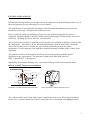
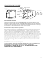
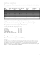
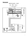
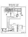
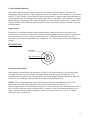
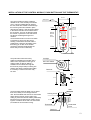
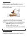
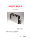
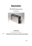
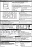
SAUNATEC GROUP Ltd
HELO HSS M and HST M STEAM GENERATOR
User and Installation Guide for models:
HELO HSS M 34, 47, 60, 77.
HELO HST M 90, 120, 140.
314 SHS 64 C
1
Technical information:
• Voltage: 400V – 415V 3N~ 50Hz (230V – 240V 1N~ 3.4 – 7.7 kW)
• Power options 3.4kW-14kW
• Protection Class: IP 20
• Water tank material: AISI 304, steel
• Two-stage control for heat elements. Not 230 V 3~
• HSS generator dimensions 325 x 315 x 185 mm
• HST generator dimensions 410 x 400 x 200 mm
Use:
•
•
•
•
•
•
Automatic draining and rinse programme
Automatic fill and water level setting
Floor or wall mounting
Digital control module:
- Temperature control
- Time control
- Light control
Control module may be fitted on inside or outside of steam room
Designed for home and professional use
Service:
• Replaceable elements – two standard, one with overheat protection fuse
• Easily serviced components:
- Circuit card
- Heat elements
- Steam room sensor
As an optional extra, the generator can be fitted with a Descaling Kit, which facilitates the addition
of citric acid solution into the tank.
2
INSTALLATION AND USE
HSS M and HST M generators are designed solely for application in steam bathing facilities. Use of
the steam generator for any other purpose is not permitted.
The manufacturer is not responsible for damage caused by equipment that has been incorrectly
installed or used or any consequential loss that may occur.
Prior to electrical connection, plumbing of pipes for water feed and steam delivery must be
completed. All joints should be properly connected and sealed using PTFE thread tape in screwed
connectors. Welding of joints is, however, recommended.
The area where the generator is installed must be dry and well ventilated to dissipate local heat from
the components – note rating is IP 20. Recommended distance from structures above and to the
sides is no less than 30 cm. Consider the space needed around the generator for routine
maintenance. For the emptying of the tank there should be drainage available in the vicinity of the
equipment.
The generator can be wall mounted in which case screws and mounting methods must be
appropriate to the wall material. The generator weights when filled with water are:
HSS, 13 kg and HST, 17 kg (approx.).
When using the automatic flushing valve, ensure that flush pipe is directed towards the drain.
HSS M and HST M generator installation
Temperature sonsor
Water connector
Control module
Push
button
400V 3N~
OK
ON
O FF
OK
ON
O FF
Steam nozzle
Flush
Placement of control panel and pressure button
Steam generator´s wall mounting holes 3 pcs
The control module can be fitted either inside or outside the steam room. When fitted outside the
steam room, a separate thermostat, which is connected to the circuit board, must always be used.
3
STEAM GENERATOR CONNECTORS
Main switch
Electricity connection
Cable for
the flush vent
Control module
cable
Measurem ents
Water connection
H
Excess pressure
vent and descaling
(optional)
HSS
H = 325
W = 185
D = 315
Steam exit
HST
H = 410
W = 200
D = 400
D
W
Water and Steam connection
Connect the ¾" flexible water pipe (included in the package) from the water connection in the
equipment (see picture) to the cold water supply in the building. Water pressure must fall between
0.2 and 10 bar. The water supply must have a stop valve, which can be used to isolate water supply
for maintenance or when steam room is not used for extended periods.
Installation must comply with local requirements
In the steam pipe connection it is recommended to use at least 18x16mm (steam generator power
3.4 kW - 9.5 kW) and 22x20 mm (steam generator power 12.0 kW - 14.0 kW) copper pipe or
similar size silicone pipe suited for high temperatures. The steam pipe diameter must be constant
throughout. Subject to the location of the generator the steam pipe should rise or fall on a steady
gradient from generator to steam room. It is essential that the pipe MUST NOT include traps as the
water which collects will cause restricted steam flow and spitting at the steam head. Any water from
condensation in the pipe must be allowed to flow freely back into the steamer or into the steam
room. If an essence pump has been fitted to the steam generator, the pipes must always be on a
downward gradient from the generator to avoid any chemicals reaching the tank. The steam pipe
should be maximum length 5 meters and fully insulated both for safety reasons and to minimise
condensation.
WARNING: Hot steam can cause burn injuries.
The electric magnetic vent used for emptying the generator’s tank is fitted to the flushing pipe. A
manual flushing stop valve can also be used with the generator. (Optional extra)
It is good practise to empty the tank after each use. This will maximise the life of this
equipment and reduces chalk/scale build-up.
4
ELECTRICAL CONNECTIONS
The steam generator will be semi-permanently connected to the electricity mains. Local regulations
must be observed.
Steam
generator
Power 400V-415V 3N~ 230V-240V 1N~
KW
Amp
Amp
230V3~
Amp
Room size
m³ *)
HSS 34
HSS 47
HSS 60
HSS 77
HST 90
HST 120
HST 140
3.4
4.7
6.0
7.7
9.5
12.0
14.0
8
12
15
19
24
30
35
1.5-2.5
2.5-5
5-7
7-10
10-12
12-15
15-18
5
7 / 6,5
9/8
12 / 11
15 / 13
19 / 17
23 / 21
15 / 14
20 / 19
26 / 25
33 / 32
All electrical connections should be completed by a qualified electrician.
*) Walls of concrete, brick or stone and cold wall lining materials will require a higher power
output to heat the room. Air conditioning and good ventilation may also need more power.
The required power can be estimated using the following formula.
Capacity (m3) x K1 x K2 = Required power (kW)
Ventilation
No ventilation
Acrylic walls
Light wall: board + tiles
Heavy wall: stone, concrete + tiles
K1 = 0.75
K1 = 0.52
K2 = 1.00
K2 = 1.25
K2 = 1.50
Two-stage control of the steam generator:
The heat elements have a two-stage control. Not 230 V 3~p.
Example:
Set temperature is 43 °C. When this temperature is reached the contactor turns off two elements,
leaving one element connected via relay-switch on the circuit board, ensuring steady temperature
and continuous steam production for the duration of the steam bath. Once the temperature has
dropped by one degree (1 °C), all the elements are switched back on. If the temperature rises by one
degree (1 °C), all the elements will be switched off. .
5
WIRING DIAGRAMS
HSS M 3,4 kW - 7,7 kW
3 N~ 400 V - 415 V
1 N~ 230 V - 240 V
50 - 60 Hz
Elements
3 N~
Contactor
6
2
5
1
Tank
Heater fuse
Main
switch
PE
L3
L2
L2
L1
L1
N
N
N
N
Gr
Gr
Earthing for cover
N
H1
N
H2
N
V1
N
V2
OLEA 72
A K S1 S2 TX RX +5 0
L
S1
Wh
Re Serial traffic to
Gr MIDI-control
Ye
LC1 LC2 B1 B2 T1 T2
N
Water valve
filling
230 V AC
L3
High level S2
Low level
Water valve
drain
230 V AC
1 N~
Wh
Thermostat
Re
Level probe
Wh
Ye On / Off
Gr Push button
Br
Alarm 12 V DC
Light control opto 24V DC max 50 mA
External voltage
354 SHS 32 A
6
HST M 9,5 - 14 kW
3 N~ 400 V - 415 V
50 - 60 Hz
Elements
3 N~
Contactor
6
5
L3
L2
2
1
L1
Tank
N
Heater fuse
N
Gr
Main
switch
Earthing for cover
Level probe
PE
High level S2
Water valve
drain
230 V AC
Water valve
filling
230 V AC
L
N
H1
N
H2
N
V1
N
V2
OLEA 72
A K S1 S2 TX RX +5 0
N
Wh
Re Serial traffic to
Gr MIDI-control
Ye
LC1 LC2 B1 B2 T1 T2
Low levelt S1
Wh Thermostat
Re
Wh
Ye On / Off
Gr Push button
Br
Alarm 12 V DC
Light control opto 24V DC max 50 mA
External voltage
354 SHS 33 A
7
HSS M 3,4 kW - 7,7 kW
HST M 9,5 kW - 14 kW
3 ~ 230 V 50 - 60 Hz
Elements
3~
Contactor
6
5
L3
4
3
L2
2
1
L1
Thermofuse
Gr
Main
Switch
Top cover
OLEA 72
PE
High level S2
Water valve
drain
230 V AC
Water valve
filling
230 V AC
L
N
H1
N
H2
N
V1
N
V2
OLEA 72
A K S1 S2 TX RX +5 0
N
White
Red
Green
Yellow
Control
keyboard
White
Yellow
Green
Brown
On / Off pushbutton
LC1 LC2 B1 B2 T1 T2
Low level S1
White
Red
Level probe
Thermostat
Alarm 12 V DC
Light control opto max. 24 V DC, 50 mA
354 SHS
8
INSTALLATION OF THE GENERATOR AND OPTIONAL EXTRAS
Temperature sensor
Water
connection
Control module
OK
ON
400V 3N~
OK
OFF
ON
OFF
Pressure button
Steam nozzle
Floor drain
Control module may be installed inside the steam room. If the control module is fitted outside the
steam room or so low within the steam room that its own thermostat does not show the correct
temperature, a separate thermostat which is connected directly to the circuit board must be used. It
must be mounted at a height of 170cm from floor level and preferably opposite the door
(see illustration).
When the push button is used, the provided limiting thermostat must always be installed, to ensure
the temperature does not rise above +50 °C. See the separate installation and connection diagrams.
Steam nozzle(s) must be fitted approx. 20 - 40 cm from the floor either under the seat or on the
wall in a position such that hot steam cannot burn the feet. When fitting nozzles, one must also
ensure that they cannot be inadvertently touched. The temperature of the steam is +100 °C and it
can cause burns.
The thermostat is fitted at a height of 170 cm from floor level and preferably on the wall opposite
the door.
The hole for the thermostat should be sealed with silicone or similar to prevent moisture ingress to
the wall. The thermostat is connected directly to the circuit card of the generator.
(see connection diagram.)
9
MIDI CONTROL MODULE FOR HSS M AND HST M STEAM GENERATOR
Light control
Temperature display
Time display
Temperature setting 25 - 50 °C
OK
Time setting 0 - 4 hours
Temperature sensor
ON
OFF
Steam generator On / Off
Digital control module
-ON / OFF button for starting / stopping the steam
-OK button
- Bathing temperature selection button (temperature display flashing)
- Bathing time selection button (time display flashing)
plus button (+) for increasing the setting of time and temperature
minus button (-) for decreasing the setting of time and temperature
- Light control button, to switch max 24 V DC, 50 mA (normal open)
10
Control Module functions
The steam is started from the control module by pressing the ON/OFF button. After this, the
temperature display will flash. The temperature may be set with the + and - buttons in 10 increments
from 25 °C min. and 50 °C max. When the desired temperature is displayed press the OK button to
set the bathing time. The display flashes and the time can be set with the + and - buttons in 1 minute
increments up to 90 minutes. Above this the display switches to hourly mode to max. 4 hours. The
display will than show full hours until countdown reaches 90 minutes, when the readout will revert
to minute mode.
Light control
Lights can be controlled with the control module button, when the led next to the button is lit.
Connectors LC1 and LC2 on the circuit board are for light control. External voltage is connected to
the circuit board at 24 V DC, which is connected to LC1. When the lights button is pressed, a
transistor on the circuit board transfers the voltage into LC2, which carries out the actual light unit
control.
PUSH BUTTON
Led light
ON - OFF switch
Functions of the button
When started with the button, the generator will run for 30 minutes and the led above the button
will light. The time cycle is fixed at 30 minutes and the generator stops automatically. The
generator can be stopped at any time during the cycle by pressing the button and the led light will
switch off. The steam generator can then be re-started as and when desired.
NOTE! When using this button control, the thermostat separate must always be fitted. The
thermostat will ensure that temperature in the steam room will not rise above 50 °C.
The two-stage control works in the pressure button version so that once the thermostat detects 50 °C
two of the heat elements will be switched off by a contactor. Once the temperature drops by one
degree, all the elements will be switched on again. If the temperature rises over 50 °C, all the
elements will be switched off.
11
INSTALLATION OF THE CONTROL MODULE, PUSH BUTTON AND THE THERMOSTAT:
55 mm
Affixing hole
The control module is factory sealed to
withstand use in the humidity of the steam
room. It can be installed directly against
the wall, fixed with suitable screws through
the two fixing holes and sealed in place
with silicone sealed. A hole should be drilled
in the wall to feed the control cable back to
the generator - this may be directly behind
the control or just below. This hole should
be silicone sealed against ingress of
moisture.
The decorative bezel in Chrome onr White
is designed to clip fit onto the control
housing. This bezel is removed with the
supplied tool. Using this tool lightly press
the locking pin in each of the 4 holes
around the perimeter whilst pulling the
frame away from the control body.
The push button has been factory
sealed to wisthstand the humidity of the
steam room. Dependent on the type of
wall the button is fitted by drilling a
suitable hole and either securing with
the back nut (acrylis walls) or setting into
position with silicone sealant (solid walls).
If necessary a surface mount box may
be used.
5 mm
Locking
Locking
Distance
between
holes
150 mm
180 mm
OK
Locking
Locking
ON
OFF
Led-light
ON - OFF switch
40 mm
Back nut
32 mm
46 mm
24 mm
The thermostat should be fitted 170 cm above
floor level, ideally on the wall opposite the
door. Drill a suitable hole and secure thermostat
either with the locknut (acrylic walls) or by
setting in place with silicone sealant (solid walls)
Ensure that a good tight seal is made to avoid
ingress of moisture to the wall. The thermostat
is inserted into its decorative casing.
.
Wall
Locking screw
24 mm
32 mm
21 mm
Thermostat
Thermostat
cover
Back nut
12
FLUSHING AND RINSE
The generator should be emptied after each use. Since chalk and scale will naturally adhere to the
internal components, it is important to drain the tank while the water is still hot. This ensures that
no chalk builds up on the elements, tank or sensors. Install an 18/16mm copper or heat resistant
silicone pipe from the flushing valve into the floor drain. The pipe's internal diameter should be
approx. 14-16mm. NOTE: draining the tank does not preclude the requirement for regular removal
of lime from the tank.
As an additional extra, the generator can be fitted with an electrically operated Drain Kit M,
(automatic flushing and rinsing function). After 15 minutes from the shutdown of the generator, the
electric flushing valve will open. When the tank is empty, the generator will refill with cold water
and flush again (rinse). This function is in both control module and pressure button versions.
In the pressure button version, when the generator has stopped, the LED by the button will flash
every second during the 15 minute waiting time before the flush and rinse. After the cycle has run,
the generator will await a new start-up command.
ELECTRIC FLUSHING VENT Drain Kit M (Optional extra)
HSS M and HST M generators flushing vent installation
- Use PTFE pipe tape to seal the thread in the electric valve connection.
- Connect the cable provided into the electric valve and lock it in place with the lock nut. The other
end of the cable is connected directly to the AMP terminals on the circuit card. (see connection
diagram.) NOTE! Electrical connections can only be made by a qualified electricia
- Install a pipe from the flushing valve into the floor drain. NOTE! Drainage of water from the tank
relies on gravity so the generator must be installed higher than the floor drain.
ALARMS
Control module
E1 At start-up or while the steam generator is running, indicates interruption in water supply to the
generator. Check that the stop valve is fully open and that the filter in the water feed connection is
clean. If the problem is in the generator, it might require service.
E2 Indicates failure in the circuit between the control module and the generator. Service is
necessary
The generator will stop when an error is detected. Fix the problem or call in service personnel.
Control module can be reset using the ON/OFF button.
13
On generator fitted with a push button, the LED light in the button will blink rapidly when an error
is detected; e.g. steam was turned on while the water supply was isolated or for some other reason
water flow to the generator was restricted. This error will also be generated if the water flow is
interrupted during operation. Error message can be reset by pressing the button. Fix the problem or
call in service personnel.
Circuit card includes 24V DC max 50 mA output for external alarms. The output is activated when
E1 or E2 errors occur or when the pressure button's led blinks rapidly. Alarms can be reset using the
ON/OFF button.
HSS M and HST M STEAM GENERATOR SERVICING
HSS M and HST M generators include a pre-programmed, automatic function, which drains and
rinses the tank after each use. This requires the use of an optional electric flush valve, Drain Kit M.
A long service life is also achieved by emptying the steamer tank immediately after use in areas
where the water is known to be hard or contain contaminants. Note! Draining the tank does not
preclude the need for the regular removal of lime from the tank.
Testing water quality and de-scaling for HSS M and HST M generators
Test strips included in the test pack supplied with the generator are used as follows: Submerge the
test strip into the water for approximately one second, lift it up and shake excess water off.
Compare the test strip to the colour coded instructions provided in the packet after waiting one
minute.
Test result: < 3° dH, Very soft water, de-scaling after 500 hours of use.
> 4° dH, Soft water, de-scaling after 100 hours of use.
> 7° dH, Medium hard water, de-scaling after 50 hours of use.
> 14°dH, Hard water, de-scaling after 30 hours of use. Installation of the limescale
removal treatment equipment is recommended.
> 21°dH, Extremely hard water. Install the limescale removal equipment and test
water hardness again.
These maintenance intervals are the maximum times as recommended by the manufacturer.
It may be worthwhile carrying out the removal of lime even more frequently, when necessary.
Warranty for the equipment is void, if the generator installation or use is not in accordance
with what has been stipulated in these instructions.
The warranty also excludes functional problems, if they are caused by so called hard or
otherwise impure water.
The steam generator must be serviced as instructed in the user manual.
14
DE-SCALING INSTRUCTIONS
As an optional extra, the generator can be fitted with a Descaling Kit, to facilitate the addition of
citric acid solution into the tank. De-scaling of HSS M and HST M steamers is carried out by
installing the pipe with filler in line between the generator and pressure release valve. (see
illustration)
Remove parts from packaging. Unscrew pressure release valve from generator and attach filler pipe
using PTFE tape provided to ensure a good seal. Use only Citric Acid recommended by Saunatec,
to ensure the process poses no health risks.
This is how you de-scale using citric acid
1. Add 50g (one bag) of citric acid to approx. 1 litre of water and mix well. Let it dissolve into
the water.
2. Lift the plastic protective cover from the generator and open the filling pipe tap.
3. Pour the liquid into the steamer's tank using a suitable funnel and close the tap.
4. Start the generator normally and let the water boil for about 10 minutes. Then stop the
generator and continue depending on whether the generator has been fitted with an automatic or
a manual flushing valve:
• Automatic flushing valve: The generator will empty and rinse itself after 15
minutes of idle time. After the first flush, generator is started again and water is
allowed to fill the tank. The generator is stopped again and it will flush and rinse
after 15 minutes. This can be repeated about 3 - 5 times.
• Manual flush valve: After boiling, let the citric acid work in the tank for about 15
minutes and empty the tank by opening the flush valve. Close the valve after the tank
is empty, start the generator again and let the water fill the tank. Stop and empty the
generator again. Repeat 3 - 5 times.
The generator is ready for use straight after de-scaling. If the steam room is filled with a citric
scent after treatment, rinse the generator again. Use of citric acid is not harmful to health.
STEAMERS IN PROFESSIONAL USE
In addition to de-scaling treatment, a further service plan is recommended if the generator is in daily
use (5 or more hours). Servicing is recommended at least twice a year so that elements, water level
sensor and the tank will be checked internally for lime-scale build-up. Parts damaged by scale
should be replaced. The tank may be cleaned following removal of the elements.
15