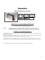
1
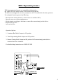
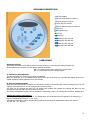
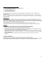
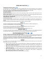
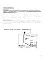
Saunatec
HELO HSX Steam generator
Mounting Instructions
User Instructions
USER GUIDE
Read Instructions carefully before fitting
NOTE:
All plumbing and electrical installation work may be carried out by authorized
personnel only and in accordance with local installation and wiring regulations.
7014095
314 SHS 30 F
CONTENTS:
Page.
General information
3.
•
Product description
Mounting and installing HSX steam generator
•
•
•
•
•
Mounting location
Mounting the generator and steam supply pipe
Electrical supply and connection diagrams
Water supply
User and service manual
•
•
•
•
•
•
•
•
•
•
•
•
•
•
4.
9.
Digital Control product description
Digital Control connections
Digital Control connection diagram
Keyboard description
Operations
Operative options
Steam bath function
Light
Fan
Essence pump
Preset bathing programs
Alarms
Drain valve
(OPTIONAL)
Maintenance
2
General Information
Product description:
The New HELO HSX steam generator is a top quality and easy-to-service steam generator designed for
domestic and commercial use.
The HELO HSX steam generator is developed to be user-friendly giving its user various options in
enjoying the steam bath. The digital control unit can be mounted inside or outside the steam room. The
steam generator can be equipped with an optional drain-valve for an automatic drain and flush program.
•
•
•
•
•
•
•
•
•
•
•
•
•
•
•
•
•
•
•
•
POWER-RANGE (400V-415V 3N~) 3,4/ 4,7/ 6,0/ 7,7/ 9,5/ 12,0/ 14,0 kW
POWER-RANGE (230V-240V 1N~) 3,4/ 4,7/ 6,0/ 7,7 kW
POWER-RANGE (230V 3~) 3,4/ 4,7/ 6,0/ 7,7/ 9,5/ 12,0/ 14,0 kW (to be ordered
separately)
SERIAL OUTLET FOR MAX 56kW
CLASSIFICATION IP20
EASY TO SERVICE
EXCHANGABLE HEATING ELEMENTS WITH THERMOFUSE PROTECTION
AUTOMATIC FLUSHING PROGRAM
AUTOMATIC WATERFILLING WITH ELECTRONIC WATERLEVEL CONTROL
EASY TO INSTALL WALL- OR FLOOR MOUNTING
DIGITAL CONTROL PANELS:
Temperature
Time
Light
Ventilation
Essence pump
4 different programs
EASY TO DESCALE
Option to turn the steam generator ON / OFF with external control.
The magnetic valve has a large flush hole through which most impurities and
chalk get flushed from the tank after each use.
Easy to maintain:
• Replaceable heating elements (3 pcs), one of which is equipped with a thermofuse.
• Lime remover (citric acid) fill port is conveniently located on top of the steam generator.
• Components can be easily replaced:
- PC board
- Heating elements
- Level probe
Plastic descale cover and descale pipe.
Access to the water tank from above the steam generator makes the
descaling process easy.
3
USE AND INSTALLATION:
The HSX steam generator is only intended for use in the heating of steambaths. Use of the steam
generator in any space other than intended can result in structural damage.
The manufacturer is not liable for any damages caused by installation in a space not intended for
steambath use, or misure of the generator.
Water and steam pipe connections must be made prior to connecting the unit into the mains.
Due care and attention must be taken when making the connections. Ensure that all joints are properly
sealed. Although thread seal tape can be used to properly seal threaded joints, soldering the joints is
recommended.
The steam generator must be placed away from water and moisture (dry room). The room must be wellventilated as the steam generator also generates heat. The minimum recommended safety clearance on
each side and above the generator is 30 cm. When placing the steam generator, also take into
consideration the space required for its maintenance.
There should be a drain nearby for draining the tank.
The steam generator can be installed freestanding on the floor or on the wall using wall fittings.
When using wall fittings, ensure you use appropriate fittings and screws for the type of construction
material of your walls. The steam generator weighs about 17 kg when filled with water.
When the automatic drain valve is used, it is recommended you use wall installation to ensure the proper
discharge pressure in the discharge pipe leading into the drain.
4
Mounting and installing HSX steam generator
Mounting location:
The HELO HSX steam generator is to be mounted in a dry space next to the steam room (i.e. in a
maintenance room, cupboard, adjoining room, loft or cellar).
The steam generator requires water- and electrical supply (see below) and a floor-drain.
The length of the steam pipe is recommended to be maximum 5 meters (16ft).
DO NOT FIT THE STEAM GENERATOR INSIDE THE STEAM ROOM.
NOTE: 1)
It is important to have unrestricted access to the generator to facilitate electrical and
plumbing connection and maintenance.
2)
The steam generator must be fitted in the upright position.(see instructions)
Temperature sensor
alt.2
Water supply
1700mm
alt.1
Power
Drain
alt.1 Control panel mounted inside steam room
alt.2 Control panel mounted outside steam room
The control panel can be fitted either inside or outside the steam room.
NOTE: The thermostat cable is connected to the control panel. The thermostat cable as well as control
panel cable can be extended with a similar cable.
5
Mounting the generator and steam supply pipe:
The steam generator can be floor standing or wall mounted using the L-brackets (included in package).
When mounting the steam generator to the wall use the keyhole slots in the L-bracket
Use suitable screws according to wall material and local standards.
NOTE:
HELO HSX-steam generator’s weight when filled with water is approx. 17 kg.
Check construction instruction when fastening the steam generator to wall for proper
fastening.
When using the optional drain valve, wall mounting is recommendable for proper downhill gradient for
the drain pipe.
Copper tube, 15mm, is recommended as steam pipe from the steam generator to the steam room.
The steam pipe shall run in a straight downhill- or uphill gradient from the steam generator to the steam
room. Avoid any “water pockets” or other dips in the steam feed pipe on its route to the steam-nozzle as
these will collect condensed water and block the pipe.
Condensation should be able to run on a downhill gradient from the steam generator to the steam room if
the generator is mounted above the level of the steam nozzle, or run back to the steam generator on a
downhill gradient from the steam nozzle to the generator if the generator is mounted below the level of the
steam nozzle.
NOTE: It is recommended to insulate the steam feed pipe for safety reason and to avoid heat
loss /condensation.
WARNING: Hot steam can cause burn injuries.
The magnetic valve for draining the steam generator tank is fitted into the draining pipe. Alternatively you
may use a manual draining valve.
The steam generator tank should be drained after each use. Draining extends steam generator’s
service life and reduces chalk build-up.
6
Electrical supply
Fused mains electricity should be terminated with an isolator adjacent to the steam generator. The supply
should be rated according to the generator to be fitted and not less than the following:
Power
3.4kW
4.7kW
6.0kW
7.7kW
9.5kW
12 kW
14 kW
400V – 415V 3N~
5 Amp
7 Amp
9 Amp
12Amp
15Amp
19Amp
23Amp
230V-240V 1N~
15 Amp
20 Amp
26 Amp
33 Amp
-------------
230V 3~
8 Amp
12 Amp
15 Amp
19 Amp
24 Amp
30 Amp
35 Amp
An isolation switch should be fitted in a convenient location outside the bathroom area so that the
generator can be switched off when not in use. Remove the vented top plate of the generator and connect
into the terminal block as follows:
3 –phase
N
1-phase
L1 L2 L3
3,4 -- 14 kW
400 V - 415 V
FACTORY SETTING
N
L1
3,4 / 4,7 / 6,0 / 7,7 kW
230 V - 240 V
Att. max. 7,7 kW
________________________________________________________________________________
3-phase
FACTORY SETTING
Used only in specific electrical systemsto be ordered separately from the factory
L1 L2 L3
3,4 – 14 kW
230 V 3~
Electrical connections are only to be done by a licensed electrician.
*) Walls made of heavy materials, such as concrete, brick or stone require a higher output to generate
sufficient heat. Ventilation must also be given extra power.
The required power output can be estimated using the fomula below.
Volume (m3) x K1 x K2 = Required output (kW)
Ventilation
No ventilation
Acrylic walls
Light construction wall: + board tile
Heavy construction wall: stone, concrete + tile
Extra heavy construction
K1 = 0.75
K1 = 0.52
K2 = 1.00
K2 = 1.25
K2 = 1.50
K2 = 2.0
7
3,4 - 7,7 kW 230 V 1N~ / 2~
6
5
4
3
6
1
6
5
4
3
2
1. 1
2
2
Gr
230V/12VAC 42VA
F1 T400mA
1
Low level
Ground
High level
IIII
IIII
Jumper for passing the timer / clock of the control panel.
2
3
4
5
6
L2 L3
3,4 - 14 kW 400 V 3N~
1
2
N
F2 T3,15 A
J1
L2
3,4 - 14 kW 230 V 3~
L1
Top cover
Essance pump 230V AC
Fan 230V AC
6
5
3
Main
switch
Water
valve
drain
230V AC
4
L1 / N
4
Thermo
Fuse 167 C
Watervalve
filling
230V AC
3
5
2.
2
1
3
4
5
6
L1 L2 L3
Levelprobe
in Tank
Light 12V AC 35W
Serial output
Control keyboard
D1
Normal open, input
for remote timer
354 SHS 36 A
8
HSX INSTALLATION:
Temperature sensor
Control panel
Water connection
400V 3N~
Steam nozzle
Flushing
The control panel can also be installed inside the steam room. Steam nozzle / nozzles are fitted
approximately 20 to 40 cm from the floor underneath a bench or a seat, or onto the wall making sure the
hot steam cannot burn your feet. The steam nozzles are directed towards the floor. When placing the
nozzles, also make sure that they will not be touched accidentally. The steam temperature is over 100
O
C and it can cause severe burns.
The thermostat is fitted to 170 cm above the floor level, preferably on the wall opposite the steam room
door. It is advisable to seal the thermostat mounting hole with a suitable substance to ensure that moisture
does not seep into the wall structure. NOTE: The thermostat cable is connected to the control panel.
9
Installing the control panel and thermostat
116 mm
The control panel has been insulated with a
suitable mass to ensure it is moisture proof
so that it can also be installed inside the
steam-room. The control panel can be fitted
directly in the wall, placed into the hole made 120 mm
for the control unit or through an acrylic
wall. The pipe hole in the steam room should
be insulated so that moisture does not reach
the wall structure.
142mm
1
on/off
2
essence
on/off
steam
on/off
3
fan
on/off
4
Ø 3mm
Seal
115 mm
Control panel's and
thermostat's cabling
34 mm
The thermostat is fitted to 170 cm above the
floor level, preferably on the wall opposite
the steam room door. If reguired the blocking
nut can be used when working with a plexiglass
wall. If the wall is thicker, you can easily make
a hole into it and sink the control into the hole
but you should insulate the hole to ensure that
moisture does not go through to the wall
structure.You can also pull in a cable through
an electrical wiring pipe and insulate the
thermostat to the end of it.
wall
20 mm
15 mm
15 mm
8 mm
Cable
Nylon screw
Blocking nut
Wall
Installation with a separate thermostat cover.
The thermostat is fitted to 170 cm above the
floor level, preferably on the wall opposite the
door. If reguired the blocking nut can be used
when working with a plexiglass wall. On
thicker walls, a hole can be drilled out and
sealed a suitable caulk to prevent moisture
from reaching building structures. The
thermostat is inserted into its casing and
secured to place with a locking screw.
Locking screw
24 mm
32 mm
21 mm
Thermostat
Thermostat
casing
Locking screw
10
HSX Operating modes
HSX steam generator have two programable working modes,
the TIME SETTING MODE or the CONTINOUS RUN MODE.
The different runningmodes are set by a jumper on the PC-borad inside the steam generator.
For setting the function proceed as following:
-
Disconnect the mains electricity (remove fuses or switch to OFF).
Open the top cover of the steamgenerator.
Set the jumper according to function.or connect the remote timing/switch device.
Replace the top cover.
Activate the fuses.
Operative Options:
1. Continous Run Mode: Jumper in ON position
2. Time Programming Mode: Jumper in OFF position
3. Remote Timing Mode: Jumper in ON position AND remote timing/switch device
connected to screw connector.
For detailed using instructions see USER GUIDE.
Low level
Ground
High level
IIII
IIII
on
1
2
3
4
Remote timing
mode.
J1
Timesetting
off
mode.
on
Continuos run
mode.
11
Water Supply
Connect the flexible ¾”water hose (included in package) to a cold water supply, or max 65°C warm water,
equipped with a manual shut off valve and with a water-pressure of min 0.2 bar and max 10 bar. Use of
water with a hardness over 7°dH or containing other impurities, may reduce the lifetime of the heating
elements if the steam generator is not properly emptied after use. (Also see descaling with citric acid).
The warranty is not valid if the steam unit has been installed or used otherwise than stated in this
manual. Functional failures caused by hard or impure water are not covered by the warranty.
16
Water
inlet
38
Steam-outlet
connection
Over pressure
valve
Main
switch
52
Control-panel inlet
Mains electricity in
Optional device inlet
Plug-connection
for drain-valve
(extra option)
Drainoutlet
12
User and Service Manual
Digital Control for HELO HSX Steam generator
WARNING
Installation and mending must be performed by qualified personnel in the respect of all the following safety norms:
DLGS N°615/96 del 12/11/96 (ECC Document 89/336 on Electromagnetic compatibility)
DLGS N°626/96 del 26/11/96 (ECC Document 93/68 on Low Voltage)
The present manual is addressed to technical personnel qualified for installation
PRODUCT DESCRIPTION
The “HSX DIGITAL CONTROL PANEL” System is an electronic device that controls the following functions:
• Steam Bath On/Off
• Adjustable bathing time and temperature
• Light
• Fan
• Essence Pump
• 4 programmable/preset programs
• Alarm analyses
DESCRIPTION OF CONNECTIONS
Power inlets
• 1 serial inlet for the keyboard
• 2 resistive level sensors (predisposed for capacitive or ultrasound level sensors)
• Supply 5VCC, digital exit: open collector NPN
• The high level sensor has to have adjustable sensitivity
• 2 dip switch
• 1 normally closed connector for a remote timer
Outputs
• 1
• 1
• 1
• 1
• 1
• 1
• 1
serial output for controlling the next control (without using a split box)
lamp 12VAC – 35 WATTS MAX.
water-charging electro valve 230 VAC
drain electro valve 230 VAC
essence pump A 230VAC MAX 400WATTS.
fan 230VAC MAX 400WATTS.
steam generator output (remote control switch coil) 230VAC MAX 3000W
Details
Board dimension: 10CMX11 CM
Second transformator to supply level sensors
13
HELO HSX DIGITAL CONTROL CONNECTION DIAGRAM
230/12VAC 42VA
TRANSFORMER
INPUT MAIN POWER
SUPPLY (230VAC)
SENSIBILITY TRIMMER
LOW LEVEL SENSOR INPUT
HIGH LEVEL SENSOR INPUT
OUTPUT POWER SUPPLY
TO TRANSFORMER (230VAC)
HEATER OUTPUT (230VAC)
BOILER FILLING
ELECTROVALVE (230VAC)
BOILER EMPTYING
ELECTROVALVE (230VAC)
ESSENCE OUTPUT
PUMP (230VAC)
FAN OUTPUT (230VAC)
DELAY TRIMMER
RL 5
INPUT VOLTAGE (12 VAC)
FROM TRANSFORMER
LAMP OUTPUT (12VAC 40W)
RL 1
RL 2
RL 3
RL 4
4
SERIAL OUTPUT GOVERNING
THE NEXT CONTROL BOARD
4
CONTROL KEYBOARD
NORMALLY OPEN INPUT
FOR REMOTE TIMER
J1 Jumper for operation mode (continous / timer)
14
KEYBOARD DESCRIPTION
4 digit LED display
on/off steam bath key with led
on/off lamp key with led
on/off fan key with led
on/off essence pump key with led
time key
temperature key
Plus key
Minus key
Memory1 key with led
Memory2 key with led
Memory3 key with led
Memory4 key with led
OPERATIONS
Operative Options
The heater can either work in the continuous running mode (A) or with the time setting program (B).
In the PCB there is a Jumper (J1) that can be selected as follows:
ON = the system works in the continuous running mode
OFF = it works with the time setting program
A. Continuous Running Mode
The plus and minus key in the time function are inhibited.
When the generator is on, the display shows temperature and if the time key is pressed the display shows the 4
central segments running rightward for a few seconds.
B. Time Programming Mode
When the time setting mode is switched on, the factory set time is 60 minutes but it can be changed from 5 to 240
minutes (with intervals of 5 min) by using the plus and minus keys.
The time can be changed also after the set steam bath program has started, by pressing the time key and
subsequently the plus and minus keys within 2 seconds.
The display alternatively visualizes for 30 seconds the temperature and for 30 seconds the remaining bathing time.
Setting the bathing temperature.
The default bathing temperature is 45 oC. The temperature can be adjusted from 30 degrees to 50 degrees (in 1
degree increments) by using the + and - keys.
The bathing temperature can be adjusted during bathing by pressing the temperature button and, within 2
seconds, the + or - buttons.
15
Personal setting steam bathing program.
There are 4 memory keys with default steam bath programs:
1. 40 minute bathing time at 40 oC
2. 60 minute bathing time at 45 oC
3. 60 minute bathing time at 50 oC
4. 40 minute bathing time at 50 oC
The steam bath will start by pressing one of the program buttons. The LED above the button indicates which
program is active.
In order to memorize your personal steam bath adjust the time and temperature by using – or + keys and then
press one of the program keys for more than 2 seconds. The program key’s LED will flash to indicate a successfully
saved programme.
Flush and rinse
The steam generator’s magnetic drain valve will automatically open 15 minutes after the bathing programme has
finished. After the tank has flushed (2 minutes) the drain valve will close and the water solenoid valve will open and
fresh cold water will fill the tank up to the upmost level probe. Once the tank is full, the drain valve will open again
and the tank will drain and remain empty ready for the next use.
During the flush and rinse cycle, the outermost segments of the screen will "go around” in circles.
During the flush and rinse cycle, you cannot start a new bathing programme nor can the cycle be interrupted.
Operation.
1. When turned on, the magnetic valve will open and the unit's tank will fill with water.
2. Once the water reaches the lowest of the level probe, the heating elements will turn on.
3. When the water level reaches the level probe, the magnetic valve will close.
4. As the water level decreases due to steaming and reaches the lower level probe, the steam generator will take
in water again until the water level probes indicate that the tank is full.
5. Steaming will continue for the set time period. When the steam room reaches the set temperature, the heating
elements will turn off. Once the temperature decreases 0.5 oC below the set temperature, the heating elements
will be turned on again.
6. Once the bathing is over, the steam generator will initiate the flush and rinse cycle after 15 minutes of
inactivity.
C. Remote Timing Mode
The system can also be connected to a remote timer that switches on and off the system.
Using this option all the automatic re-starts of the alarm modes are inhibited. When an alarm stops the treatment
for safety reasons during the remote timing mode , the system can be re-started by only the operator.
16
STEAM BATH FUNCTION
.
Temperature and Time setting
The temperature set by default is 45°C and it can be changed from 30°C to 50°C with steps of 1°C by using the
plus and minus key. The temperature can be changed also after the set steam bath program has started, by
pressing the temperature key and subsequently the plus and minus keys within 2 seconds.
Time can be changed by using the time key and the plus and minus keys.
The Steam generator
When the user starts the treatment the electro valve starts taking in water, when the water reaches the low level
sensor the heating starts.
When the water reaches the high level sensor the electro valve closes off; as soon as the high level sensor does not
feel the water the electro valve opens and it closes when the right level is reached.
Steam generator cleaning cycle
The cleaning cycle is an automatic operation and is very important because it prevents the formation of chalk and
bacteria in the water tank.
It is automatically activated 15 minutes after the steam generator has stopped. The drain electro valve opens for 2
minutes. The tank is filled with water up the high level sensor, and the draining electro valve opens again for two
minutes.
During the cleaning cycle the external segments of the display go around in circles.
LAMP
The led is on when the lamp is off. Press the lamp key and the led switches off while the lamplight is on.
The lamp works independently from the steam generator .
FAN
The fan switches on automatically when the generator stops, and then the fan runs for 30 min.
During the steam bathing the fan can be switched on and off.
The led shows the status of the fan: on when the fan works and off when the fan is off.
ESSENCE PUMP
The essence pump starts working automatically when the set temperature is reached. It can stopped and restarted
by pressing the essence pump key. The led is on when the pump is on and off when the pump is off.
PRE PROGRAMMABLE BUTTONS
..
There are 4 memory keys with default steam bath programs.
In order to memorize a personal steam bath, adjust temperature and time by using the plus and minus keys and
then press a memory key for more than 2 seconds: in this way the customized steam bath program is saved in the
memory key. The Memory keys all work as starting keys for the steam bath program
The led of the memory key is on when the chosen steam bath program is on. When the user is programming a key
the led blinks, while saving the new data, in order to show that the reprogramming operation has been successfully
performed.
ALARMS
If a problem occurs in the system while in function, the display visualizes an alarm number (A1, A2, A3, A4), which
helps identify the nature of the problem.
•
•
•
•
A1: If the high level sensor does not feel the water after 5 minutes from activating the steam bath, the
system times out and it can be re-started. If the system does not get restarted after 5 minutes then the
draining valve empties the water tank.
A2: If the low level sensor does not feel the water for more than 1 minute during the treatment, the
heating stops working. If the operator doesn’t make any operational actions within 5 minutes then the
whole system times out.
A3: If the set temperature is not yet reached after 30 minutes the display visualizes the alarm. The steam
bath continues according to program. Check the set temperature, sensor position, ventilation and
dimensioning of the generator if the A3 shows again.
A4: If the temperature level does not work all functions are inhibited
17
Operating optional devices.
Light controls.
The ligh control button operates independently of the steam generator. The button can also be used to
control a 12 V AC light and also a 12V AC external light control. The LED for the light button will be
illuminated when the lights are off.
Fan controls.
The fan function works only if the external fan is connected to the pc board. The fan controls will
automatically activate for 30 minutes after the steam bathing programme has finished. During bathing the
fan can be turned on or off pressing the “fan” button in the control unit. The control button LED will be
illuminated when the fan is on. The control voltage is 230V.
Essence pump controls.
The essence pump can be turned on or off by pressing the essence on/off button . The essence pump is
connected as shown in the picture below i.e. install the thermostat included in an essance pump package
into the steam pipe. The control button’s LED will be illuminated when the essence pump is turned on.
Control voltage 230V.
Essence pump connection
ESSENCE PUMP
N
L
Temperature sensor
70 °Celsius. Attached to
the steam pipe with a
cable tie
3 A fuse
PC board
OLEA 40
N L1 L2 L3
Steam
connector
I I II
I I II
Essence pump
control 230V
Circuit board has
AMP-connections
18
DRAIN VALVE (Optional)
Drain valve is easy to mount: screw on the magnetic valve and plug-in the cable.
STEAM GENERATOR MAINTENANCE:
FLUSH AND RINSE:
The steam generator has an automatic flush and rinse cycle. 15 minutes after the bathing programme has
finished or the programme has been manually aborted, the electronic drain valve will open. After the flush
the steam generator will fill its tank again with cold water and flush it again (rinse).
By emptying the steam generator tank straight after use, the life length of steam generator is improved
even in areas where water quality leaves room for improvement. Flushing the tank is not a substitute for a
regular chalk removal.
After the flush and rinse cycle, the steam generator will shut down to stand-by mode until the next bathing
programme is initiated.
Testing the water quality and descaling the HELO HSX-steam generator:
Water hardness test: Perform a water test with the test strips enclosed in steam generator package.
Dip the test strip briefly (1 sec) in water and shake off excess water. Check the test strip after 1 minute.
Test result: < 3° dH, very soft water, descaling after 500 hours of use.
> 4° dH, soft water, descaling after 100 hours of use.
> 7° dH, semi hard water, descaling after 50 hours of use.
> 14°dH, hard water, descaling after 30 hours of use, installation of a water-softener is
recommended
> 21°dH, very hard water, Install a water softener.
These numbers are recommendations from the manufacturer, descaling with citric acid can be
carried out more often.
The product warranty will be void if the steam generator has been incorrectly installed or it has
been used in a manner other than described in the user manual.
The warranty also expressly excludes operational faults if they are caused by so called hard water
(water with high levels of chalk or otherwise impure water).
The steam generator must be maintained as described in the user manual.
19
DESCALING INSTRUCTIONS.
The descale procedure with the HELO HSX-steam generator is easy to carry out. Use only the
recommended citric acid according to the instruction beneath.
Helo HSX-steam generators are supplied with a plugged descale access pipe for filling the tank with the
mixture.
Descale instructions step-by-step.
1.
2.
3.
4.
Add 50g of citric acid into 1 liter of fresh water and mix well.
Open the descale plastic cover on the generator and open the cap on the pipe.
Pour the mixture into the tank of the steam generator and close the cap.
Start up the steam generator and let the citric acid solution boil in the tank for approx. 10 minutes.
Stop the generator and depending on if there is a automatic or manual valve proceed as following:
a. Automatic drain valve: The tank drains and flushes itself 15 minutes after the stopcommand. After the drain and flush, start the generator and let it fill up with water before
pressing the stop button again and Wait for the tank to drain again. This flush-procedure
can be carried out 3-5 times.
b. Manual drain valve: After the boiling procedure wait and let the citric acid stand in the tank
for approx. 15 minutes, then drain the tank by opening the manual valve. After the tank is
empty close the valve and start up the generator again and let it fill up with fresh water.
After that press the stop button and drain the tank again. This flush-procedure can be
carried out 3-5 times.
The steam generator is ready for use after descaling and if a smell of citrus occurs in the steam
room; it is not harmful to the health and can be eliminated by flushing the generator again.
STEAM GENERATOR IN PUBLIC USE.
In addition to the descale procedure above it is advisable to maintain a proper service interval on a steam
generator in public use (run-time 5 hours or more per day). This service, for example made every 6th.
month (more often if the water-conditions require), should consist of a visual check on the interior of the
tank, the scale build up on elements and level probe.
The tank can be cleaned on the inside through the fastening holes of the elements.
20
Saunatec
HELO HSX Steam generator
Split Kit 2
Split Kit 3
Split Kit 4
Split kit user and mounting instruction
Read Instructions carefully before fitting
NOTE:
All plumbing and electrical installation work may be carried out by authorized
personnel only and in accordance with local installation and wiring regulations.
SPLIT KIT 1, 2, 3 with adjustable drain cycle.
The HSX Split kit is used when connecting 2 or more (max 4) HSX-steam generators to generate steam
for bigger steam rooms.
The Split kit contents the cables and connectors needed. The PC-board is equipped with a DIP-switch (see
drawing) for activating each steam generator and adjusting the drain cycle.
The HSX steam generators adjustable drain cycle-feature that drains and flushes the tank every 3 hour,
3hour 20 min. or every 3hour 40min. after the procedure the steam generator continues to produce steam.
In case 4 generators are connected together, 2 of them are drained simultaneously.
21
Mounting the Split kit:
1. Remove the short plastic-end cover
and the metallic top cover from the
HSX steam-generator.
2. Open the 19mm diameter predrilled hole on the inside of the
shorter plastic-end cover of the
HSX-steam generators.
3. Mount the Split-kit cable and strain
relief to the opened hole in the
plastic end cover
pre-drilled
holes.
21mm
21mm
19mm/Split-Kit
1
1.
2./ 3.
4. Connect the wire/wires from the
Split-kit to the PC-board connector
according to the drawing and set the
DIP-switch 1 and 2, in the
following positions according to the
steam generators connection
number:
DIP1 DIP2
HSX 1:
off
off
HSX 2:
on
off
HSX 3:
off
on
HSX 4:
on
on
5. Set the adjustable drain cycle, dip 3
and 4, on the PC-board on each
HSX steam generator
DIP3 DIP4
No drain cycle
3 hour
3hour 20min.
3hour 40min.
off
off
on
on
off
on
off
on
4.
22
HSX Flowchart
Start
Press
pushbutton
RL1
engages
-check power supply
-check relay
-Tank is allready filled with water
NO
YES
Solenoid Valve opens
Water into tank
(appr.1min 20sek)
NO
-check watersupply
-check solenoid valve
-check wiring
-check waterlevel probe
NO
-check waterlevel probe
YES
LD1
on
YES
Water tank is full.
NO
YES
RL5
engages
NO
NO
YES
Heating element activates
YES
Boiling off water in the Tank. Steam into
room
NO
If time to fill tank longer than 1.30 min
-check water pressure
-check solenoid valve for dirt particles
-check drain valve for leakages
-check termofuse
-check heating elements
-check relay
If water boils but no steam to room
-check steam pipe and steamoutlet
LD1
off
Waterlevel low
RL1
engages
Solenoid valve opens
water is filled to high level
23