1
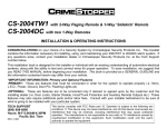
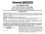
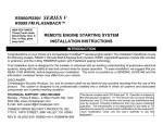
SERIES I
CS-2205ADVTW1 Deluxe 2-Way LED Paging Security System
INSTALLATION & OPERATING INSTRUCTIONS
CONGRATULATIONS on your choice of a Security System by Crimestopper Security Products Inc. This booklet contains
the information necessary for installing, using, and maintaining your CS-2205 Advantage alarm system. If any questions
arise, contact your installation dealer or Crimestopper Security Products Inc. at the Tech Support number below.
This installation book is designed for the installer or individual with an existing understanding of automotive electrical
systems, along with the ability to test and connect wires for proper operation. To ease installation, we suggest that you
READ THIS MANUAL before beginning your installation. This book is provided as a GENERAL GUIDLINE and the
information contained herein may differ from your vehicle.
*IMPORTANT INFORMATION: Primary and Optional Features
-PRIMARY: These are features that must be connected in order for the system to operate properly i.e. Siren, L.E.D., Power,
Ground, Door Pin, and Flashing Lights etc.
-OPTIONAL: These are features are to be connected only if desired or agreed upon by the customer and the installing
dealer (i.e. Door Locks, Starter Disable, Hood/Trunk Protection and Auxiliary Remote Outputs etc.) These features may also
require additional parts and/or labor fees. Consult with your installer beforehand to be sure of what is going to be installed
with your particular system.
TECH SUPPORT
(800) 998-6880
Hours: M-F 8:00AM-4:30PM
Pacific Std. Time
REV B 6.2005
This device complies with FCC Rules part 15. Operation is subject to the following two
conditions: 1) This device may not cause interference, and (2) this device must accept any
interference that may be received, including interference that may cause undesired operation.
The manufacturer is not responsible for any radio or TV interference caused by unauthorized
modification to this equipment. Such modification could void the user's authority to operate the
equipment.
TABLE OF CONTENTS
Installation Cautions & Warnings…….……………………………………………………………...………………………………..2
Suggested Component Mounting………….…………………………………………………………….……………………….…...3
Wiring (Connectors H1-H8)…………………………………………………………………………………………………………3-12
Power Door Lock Wiring...………………………………………………………………..……………………………………….…4-6
.
Starter Disable Wiring…………………………..…..…………………………………………………………..………………….10-11
Antenna Diagram………………….……...…………………………………………………………………….…...…………………13
Option Programming……………..………………………………………………………..…………..…….……………………14-18
Programmable Option Reset………………………...……….…………………………………………………….…………….….16
Main System Wiring Diagram………………….…………………………………………………………………………………….19
Remote Programming……..……………………………………………………..………………………....………………………..20
Operation.………………………..…………………………………..….……………….…………………………………….……21-32
2-Vehicle Operation…….…………………………………..….………………………………….…….…………………………….23
INSTALLATION CAUTIONS & WARNINGS
BEFORE BEGINNING, check all vehicle manufacturer cautions and warnings regarding electrical service (AIR BAGS, ABS
BRAKES, AND BATTERY).
TO PREVENT A POSSIBLE DEAD BATTERY remove vehicle dome light fuse while working on the vehicle. MAKE
CERTAIN TO REINSTALL FUSE PRIOR TO TESTING FOR DOOR TRIGGERS.
DO NOT EXCEED MAXIMUM OUTPUT RATINGS! - SERIOUS DAMAGE MAY OCCUR. LIMITS FOR ALARM FUNCTIONS
ARE LISTED WHERE APPLICABLE.
REMOVE MAIN SYSTEM FUSE (S) before jump starting the vehicle or charging the battery at high boost. DAMAGE MAY
OCCUR TO SYSTEM IF PROPER PRECAUTIONS ARE NOT OBSERVED.
DO NOT Mount the control unit or wiring harness in the engine compartment or anywhere they can become entangled with
moving parts such as brake/gas/clutch pedals, or the steering column. The alarm control module should be mounted in a
concealed location. The antenna wire should be routed away from any metal if possible. Do not alter the length of the
antenna, ground it, or route it with other wires.
2
CONTROL MODULE/COMPONENT MOUNTING
CONTROL MODULE: The alarm control module should be mounted in a concealed location. DO NOT mount the control unit
in the engine compartment. Fasten the module to a bracket or wire harness using the cable ties provided.
ANTENNA MODULE: For optimum range and performance, the antenna/receiver module should be located high up on the
front windshield glass. For example: behind the rearview mirror. Note: Window tint or films may decrease the range of the
system. The mounting surface for the antenna should be clean and dry.
SIREN MOUNTING: Mount the siren under the hood to fender-well or other body surface with the open end facing
downward. Run the red siren wire through the firewall using a rubber grommet. Ground the black wire to the body.
LED: Mount the LED in a visible location on the dashboard or console.
SHOCK SENSOR: Mount the included shock sensor with wire ties to an under dash wire harness or fasten with screws to
firewall or side paneling.
OVERIDE/PROGRAM BUTTON: Mount the Override/Program push-button in a hidden but accessible location. It is used for
emergency disarm without the use of the transmitter and for programming certain features.
(H1) 6-PIN WHITE CONNECTOR
RED WIRE: +12V POWER INPUT (3 Amp Fuse)
Connect to a +12Volt source with the supplied fuse and fuse-holder. We recommend the connection to be at the Vehicle’s
Battery Positive Terminal.
BROWN WIRE: (+) SIREN OUTPUT (3 Amp Max.)
Connect to the siren’s RED wire. Connect the Siren’s Black Ground wire to the chassis close to the siren.
BLACK WIRE: CHASSIS GROUND
THIS WIRE NUST BE CONNECTED TO THE CHASSIS METAL OF THE VEHICLE. Scrape away any paint or dirt to ensure
a good connection.
WHITE WIRE: +12V FLASHING PARKING LIGHT OUTPUT (optional)
Connect to switched parking light wire at back of light switch or connect directly to one of the parking lights at the front of the
vehicle. European vehicles may require additional parts due to separate left and right circuits.
3
RED/WHITE WIRE: INPUT SOURCE FOR FLASHING PARKING LIGHT
Connect to a +12 Volt source or Chassis Ground depending on the vehicle Parking light circuit.
WHITE WIRE: +12V FLASHING PARKING LIGHT OUTPUT (optional)
Connect to switched parking light wire at back of light switch or connect directly to one of the parking lights at the front of the
vehicle. European vehicles may require additional parts due to separate left and right circuits.
(H 2) 4-PIN ORANGE CONNECTOR: SHOCK SENSOR
4-PIN SENSOR PLUG:
RED WIRE: SENSOR +12V POWER
BLACK WIRE: SENSOR GROUND
BLUE WIRE: NEG. TRIGGER
GREEN WIRE: NEG. WARN-AWAY
(H 3) 2-PIN WHITE CONNECTOR: LED INDICATOR
LED PLUG: LED Indicator (RED FLASHING LIGHT)
(H 4) 6-PIN WHITE CONNECTOR: POWER DOOR LOCK WIRING
6-PIN DOOR LOCK PLUG 18 GA. (Optional / ON-Board Relays):
BROWN:
BLUE:
VIO/WHT:
WHITE:
GREEN:
VIOLET:
DOOR UNLOCK Relay Term. #87A:
DOOR UNLOCK Relay Term. #30:
DOOR UNLOCK Relay Term. #87:
DOOR LOCK Relay Term. #87A:
DOOR LOCK Relay Term. #30:
DOOR LOCK Relay Term. #87:
Normally Closed
Common [Unlock Output]
Normally Open [Polarity Input for Unlock relay]
Normally Closed
Common [Lock Output]
Normally Open [Polarity Input for Lock relay]
4
(H 4) POWER DOOR LOCK WIRING
DETERMINING DOOR LOCK TYPE: We recommend determining the type of locking system the vehicle has before
connecting any wires. Incorrect connection may result in damage to the alarm and/or vehicle locking system. This door lock
information is provided as a guide. Your vehicle may differ.
Negative Trigger (-): Many Imports; Late model Ford & General Motors
Negative trigger door lock systems send a Negative (Ground) pulse to existing factory relays to lock and unlock the vehicle
doors.
Positive Trigger (+): Many General Motors; Chrysler / Dodge / Plymouth
Positive trigger door lock systems send a Positive (+12V) pulse through factory relays to lock and unlock doors.
Reverse Polarity: Many Ford/Lincoln/Mercury/Dodge/Chrysler/Plymouth and early 90’s GM Trucks
Reverse Polarity systems use no relays, but instead the door lock/unlock motors are controlled directly from the lock and
unlock switches in the door. The lock and unlock wires rest at Negative Ground when not in use. When the lock or unlock
button is pressed, one of the circuits is “Lifted” and replaced with +12V causing a lock or unlock.
Single Wire (Dual Voltage): Late model Chrysler/Dodge/Plymouth Vehicles, some 2000-UP GM
Dual Voltage systems have lock/unlock switches that send varying amounts of Positive voltage OR Negative ground current
to the SAME wire for both lock and unlock. When the vehicle’s Body Computer Module (BCM) or door lock module senses
different voltages on this wire, the system will either lock or unlock. Single wire door lock systems require relays and
resistors.
Databus Systems (2003 GM Trucks & SUV’s, ‘99-05 Jeep Grand Cherokee)
Databus systems send low current “Data messages” to the door lock controllers in order to lock and unlock the vehicle. To
install aftermarket systems in these vehicles, an interface module is required that converts the regular lock/unlock pulses into
“Data messages” to allow locking & unlocking. Interface modules are sold separately.
5
(H 4) POWER DOOR LOCK WIRE DIAGRAM
6
(H 5) ANTENNA/PAGER SWITCH
Transmitter Antenna: Two-way Pager Antenna.
Pager switch: Pages your Two-way pager in an event you lose your keys (Two-way pager only)
(H 6) KNOCK SENSOR (Optional)
KNOCK SENSOR (Optional): Sensor not included in kit.
(H 7) PROGRAM/OVERRIDE BUTTON
2-PIN PLUG (LARGE): PROGRAM/OVERRIDE PUSH BUTTON
PROGRAM/Emergency Override (Disarm)
For Programming:
Used to change options on program table and to code remote:
For Emergency Override:
If you have lost the transmitter or it stops working for any reason and the Alarm is armed, you will have to
Disarm the system manually. Open the door with the key [alarm will sound], turn the ignition on, and press the
Override/program button once. The Alarm will disarm and allow you to use the vehicle until you can repair/replace the
remote. Valet mode also prevents Passive Arming.
7
(H8) PIN WIRING DIAGRAM
1. Black/White Wire: (-) 200mA Dome light Output (Require a Relay)
2. Black/Violet Wire: (-) 200mA Auxiliary 3 Output (Option, may Require a Relay)
3. Orange/Black Wire: (-) 200mA Factory Disarm (OEM) Output (Option, may Require a Relay)
4. Black/Red Wire: (-) 200mA Auxiliary 2 Output (Option, may Require a Relay)
5. Brown/White Wire: (-) 200mA Horn Honk Output (Option, may Require a Relay)
6. Gray Wire: (-) 200mA (Trunk Pop) Auxiliary 1 Output (Option, may Require a Relay)
7. Blue/White Wire: (-) 200mA Passenger Door Unlock Output (Option, may Require a Relay)
8. Orange/White Wire: (-) 300mA Negative Starter Disable (Normally Open)
9. Orange Wire: (-) 300mA Negative Starter Disable (Normally Close)
10. Violet Wire: Zone 3 / Positive Door Pin Trigger Input
+12V
11. White/Black Wire: Negative Door Unlock Control Input
12. White/Green Wire: Negative Door lock Control Input
13. Yellow Wire: Zone 5 / To Ignition Switched + 12V
14. Green Wire: Zone 3 / Negative Door Pin Trigger Input
+12V
15. Blue Wire: Zone 2 / Hood Trigger Ground Input
16. White Wire: Zone 2 / Trunk Trigger Input
8
+12V
WIRING 16-PIN CONNECTOR
BLACK/WHITE WIRE: DOME LIGHT Illumination Output (Optional, Requires relay)
Negative Dome Light System: Connects to terminal 85 of a relay. Connect terminal 86 + 12V Constant. Connect terminal 87
to Chassis Ground and Connect Terminal 30 to the Negative dome light activation.
Positive Dome Light System: Connects to terminal 85 of a relay. Connect terminals 86 & 87 to + 12V Constant. Connect
terminal 30 to the Positive dome light activation circuit.
BLACK/VIOLET WIRE:(-) NEGATIVE AUX REMOTE OUTPUT 3 (Optional, may require a relay)
Negative output when the unlock and trunk button is press at the same time. This wire connects the same way as Remote
Output 1 see GRAY WIRE description below. (To change the functions of this output go to program option number 21).
ORANGE/BLACK WIRE:(-) FACTORY OEM DISARM OUTPUT
This wire provides a Ground pulse to disarm vehicles’ Factory anti-theft system. Connect this wire to the vehicles’ anti-theft
disarm wire. This wire is sometimes found coming off the Driver’s door key switch or at the Factory Anti-theft control module.
BLACK/RED WIRE: (-) NEGATIVE AUX REMOTE OUTPUT 2 (Optional, may require a relay)
Negative output when the lock and trunk button is press at the same time. This wire connects the same way as Remote
Output 1 see GRAY WIRE description below. (To change the functions of this output go to program option number 20).
BROWN/WHITE WIRE: (-) HORN HONK OUTPUT (Optional, may require a relay)
Connect to the Negative Horn Trigger wire usually located near the steering column. If the vehicle horn circuit requires +12V,
then a relay is required. RELAY WIRING: Connect the Brown/White wire to terminal 85; connect relay terminals 86 and 87 to
+12V constant power. Connect terminal 30 of the relay to the +12V positive device/circuit to be activated.
GRAY WIRE: GRAY WIRE: (-) NEGATIVE AUX REMOTE OUTPUT 1 (Optional, may require a relay)
This will become a 1 second pulse ground by pressing the trunk button on the transmitter for three seconds. The current
capacity of this wire is 200mA. This feature allows you to remote control trunk release or other electric device. This output
can also by program to provide the following type of output: latched and timed control output. (To change the functions of this
output go to program option number 19).
BLUE/WHITE WIRE: (-) PASSENGER(s) DOOR UNLOCK OUTPUT (Optional, requires relay)
Connects to unlock circuit for passenger door(s) when using separate driver’s door unlock option. Double press unlock button
within 2 second to activate passenger unlock output.
9
ORANGE/WHITE WIRE: NEGATIVE STARTER DISABLE (Normally Open)
This wire should be connected to the Orange wire of the pre-wired relay socket for the starter disable. Connect the Yellow
wire of the relay socket to the Ignition switched wire on the vehicle. Remove the white wire from the relay socket with a small
flat head screwdriver an insert it in pin # 87. Cut the vehicle starter wire and connect each half to the Red and White wire on
the relay socket. See (Normally Open) Starter disable diagram on page 11.
ORANGE WIRE: (-) NEGATIVE STARTER DISABLE (Normally Close)
This wire should be connected to the Orange wire of the pre-wired relay socket for the starter disable. Connect the Yellow
wire of the relay socket to the Ignition switched wire on the vehicle. Cut the vehicle starter wire and connect each half to the
Red and white wire on the relay socket. See (Normally Close) Starter disable diagram on page 11.
Note: READ BELOW before connecting starter disable! Normally OPEN use Orange/White wire. For Normally Close
use Orange.
Normally Closed Starter disable is the standard type used with most alarm systems today. This circuit will disable the
Starter while the alarm is armed or has been triggered. If 12V power is removed from the system, the Battery goes dead; the
relay will revert back to the closed position. See Normally Close Diagram.
Normally Open Starter Disable is a High-Security circuit that will disable the starter while the alarm is armed or triggered
AND if the unit is unplugged or removed from power. This means that if the vehicle’s Battery goes dead or the unit is
unplugged from the vehicle, the car will still not start. We only recommend this type of circuit if you can install a hidden highcurrent toggle switch to defeat the Normally Open disable in case of a dead battery or if the unit is unplugged/remove for
service. (Toggle not included) See Normally Open Diagram.
10
STARTER DISABLE DIAGRAM
IGN
SWITCH
NORMALLY CLOSED STARTER DISABLE
START WIRE
IGNITION WIRE
CUT
STARTER
WHITE
87
Yellow
(ignition)
86
RED
87A
30
85
ORANGE
ORANGE
(From the Alarm)
N/C = NORMALLY CLOSED
IGN
SWITCH
NORMALLY OPEN STARTER
START WIRE
IGNITION WIRE
Remove white
wire from Relay
harness from pin
(87A) Reinsert it
in pin (87) with a
small screwdriver.
CUT
STARTER
WHITE
Remove
Yellow
(To ignition)
87
86
HIDDEN TOGGLE
SWITCH
(NOT INCLUDED)
RED
87A
30
85
ORANGE
ORANGE/WHITE
(From the Alarm)
N/O = NORMALLY
OPEN
11
VIOLET WIRE: (+) DOOR TRIGGER
Connect to Positive type door switches that show +12 Volts when the door is open and Ground when the doors are closed.
WHITE/BLACK WIRE: DOOR UNLOCK CONTROL INPUT
Connect Door Unlock input from aftermarket switch. This is a negative Door Unlock input that controls the onboard relay for
Power Door Unlock output wire.
WHITE/GREEN WIRE: DOOR LOCK CONTROL INPUT
Connect Door Lock input from aftermarket switch. This is a negative Door Lock input that controls the onboard relay for the
Power Door Lock output wire.
YELLOW WIRE: IGNITION SWITCHED “ON” and “START” +12 VOLTS
Connect to a (+) Ignition wire that shows +12 Volts when the key is in both the “ON” and “Cranking” positions.
GREEN WIRE: (-) DOOR TRIGGER
Connect to Negative type door switches that read ground when a door is opened and 12 volts when all doors are closed. In
the case of isolated door triggers, you may need to run additional wires from other doors OR go directly to the dome light.
BLUE WIRE:(-) HOOD TRIGGER
The Blue wire is used for a grounding hood pin switch. Connect to existing pin switches that read ground when open. If no
existing switches are available, install new pin switches if desired. Note: DO NOT mount new pin switches in water pathways
WHITE: (-) TRUNK PIN SWITCH INPUT
Input trigger for a grounding trunk pin switch. Connect to existing trunk pin switches that read ground when open. If no
existing switches are available, install new pin switches if desired. Note: DO NOT mount new pin switches in water
pathways.
12
WINDSHIELD
RECOMMENDED
ANTENNA
LOCATIONS
CS-2205ADVTW1 Antenna System
Window Mount
Antenna
Antenna
Wire
CS-2205ADVTW1
13
PROGRAMMABLE OPTIONS
You can program multiple options in one session if you start with the lowest option and continue on to higher options [if needed]
without repeating steps #1-3 below. For example, you can follow the programming steps to change Option #2 to “OFF” by pressing
the lock button on the remote, then you can continue pressing the program button additional times to get to a high number option
and change the setting without having to repeat Steps 1-5. You can only go from low to higher option numbers in one session.
To Engage Option Programming:
1. Turn Key to the ON position
2. Press program / valet button 5 times, after a few seconds the unit will flash the lights 5 times.
3. Push the valet/program button [again] the number of times that corresponds to the option number desired (1 thru 25).
You must get a light flash after each button press. See chart on next page for option list.
4. When you reach the desired programming level, Press button #1, #3 or #4 to change the option.
5. Turn Ignition OFF and check for changed features. Change each option individually repeating #1-4.
AUX Channel 1 (2 / 3 / 4) Timed Output Programming
1. After you reach the desired Aux Channel programming option, press transmitter button #4 ( symbol). The LED, Siren
and Horn flash 4 times to indicate you are in Timer Programming mode”.
2. Press and hold the valet switch, the timer will immediately start.
3. When the desired interval has passed, release the valet switch. You will get one long chirp for confirmation. (Set to any
interval between 1 second and 2 minutes)
Note 1: If your built-in timer controls window/sunroof closure in your car DO NOT change the timer setting! This
requires installer-only programming. Changing the value will adversely effect operation and may cause
damage.
Note 2:
Momentary output = The momentary output selection will output a negative signal from the Channel 2, 3 or 4 output
immediately when the channel 2, 3 or 4 button is pressed and will continue until the button is release.
Latched output = The latched output selection will output a negative signal as soon as the Channel 1/2/3/4 button is
pressed and will continue until the button is pressed again.
Latched output / reset with ignition = The latched / reset with ignition output selection operates just like the latched
output but will reset or stop when the ignition is turned on.
14
PROGRAMMABLE OPTION TABLE
Option
#
CS-2205 Alarm
Function
TX Button #1
(*DEFAULT)
TX Button #2
TX Button #3
TX Button #4
*All Functions
No Warn-A-Way
No Arm/Disarm Pulse
Lock Only
Unlock Only
1
Horn Pulse
Door & Hood Trigger
Only
2
Auto lock with Ignition
OFF
*ON = Lock/Unlock
3
Passive/Active Arming
ON = Passive Arm
*OFF = Active Arm
4
Active Re-Arm
ON
*OFF
5
Passive Locks
ON
*OFF
6
Parking Lights on
w/Disarm
OFF
*ON
7
Arm with Ignition ON
OFF
*ON (Sensors OFF with Ign. ON)
8
Siren Chirps w/Arm/Disarm
OFF
*ON
9
Override PIN Code
ON
*OFF
10
Disarm on Trunk pop
OFF
*ON
11
Open Door Warning
5 seconds with page
*60 seconds with page
5 seconds without page
60 seconds without page
12
Lock/Unlock Pulse
3.5 Sec.
*0.80 Sec.
0.50 Sec.
Comfort Feature Windows
Up(10 sec. lock pulse)
13
Double Unlock Pulse
ON
*OFF
14
Option not use
15
Option not use
16
Enable Range Check
ON
*OFF
17
"TEST MODE"
Zone 2 & 3
*OFF
Zone 1 & 4
18
Panic Mode
OFF
*ON (With Ignition On or Off)
With Ignition Off
19
Aux Channel #1
Latched
1-sec
Reset with Ignition ON
Timed 1 to120 Seconds
20
Aux Channel #2
Latched
*Momentary
Reset with Ignition ON
Hold Valet Button
21
Aux Channel #3
Latched
*Momentary
Reset with Ignition ON
For time period
22
Aux Channel #4
Latched
*Momentary
Reset with Ignition ON
Then release
23
P#7 Blue/white wire
Aux Channel #4
*2 Step Unlock
24
P#1 Black/white wire
Aux Channel #4
*Dome Light
25
Option Reset to Default (*)
*Reset options
15
ON (Sensors ON with Ign. ON)
PROGRAMMABLE OPTION RESET
This system provides a reset method to restore all options to FACTORY DEFAULT VALUES as listed in the “Button #2”
column of the programmable option chart on pages 18-19. This can be helpful if you have lost track of the option settings on
your system, or when you are moving the system from car to car and want a “clean slate”.
1. Turn Key to the ON position
2. Press program/valet button 5 times, after a few seconds the unit will flash the lights 5 times.
3. Then, press the program/valet button 25 times. Press carefully,do not lose count! You must get a light flash each time
you press the button. If the unit didn’t flash the lights, then the system did not register your press.
4. Press unlock button on Remote. Program option are now reset to default values.
OPTION PROGRAMMING
1. HORN PULSE:
Use this option to control the Brown/White wire to determine how your Horn honks, Arm and Disarm, with all Functions, with
warn-a-way on your shock sensor or with trigger only.
2. AUTOLOCK WITH IGNITION
This option controls whether the doors will automatically lock when the ignition is turned on and will unlock when the ignition
is turned off.
3. PASSIVE ARMING
This option controls the Passive (Automatic) arming feature. If ON, arming will occur 30 Seconds after the ignition is turned
off and the last door has been closed. The LED will begin flashing rapidly. If a door is reopened, the system will wait (LED
will turn off) until the door or zone is close before arming.
4. ACTIVE RE-ARM
Active Re-arming allows the system to re-arm itself 60 seconds after disarmed with the transmitter if a door has not been
opened. This is handy if the vehicle is accidentally disarmed without your knowledge. Note: Active re-arm is reset by dome
light illumination.
5. PASSIVE LOCKS
This option controls whether the doors will also lock when Passive Arming occurs. Note: May increase the risk of locking
keys in the vehicle.
6. PARKING LIGHTS ON WITH DISARM:
Keeps parking lights on when system is disarmed to assist in locating and providing illumination near your vehicle when
approaching at night for safety.
16
7. ARM WITH IGNITION ON:
This feature allows the system to arm when the ignition key is on or off, or arm the system with key off only.
8. SIREN CHIRPS WITH ARM/DISARM:
With this feature, siren chirps with Arm/Disarm can be programmed either ON or OFF when using the regular Lock/Unlock
buttons. When chirp are OFF, the Flashing parking lights will be the only Arm/Disarm confirmation.
9. OVERIDE PIN CODE:
This feature allows you to enter your personal Pin Code for high security to disarm the alarm with out your remote.
Also in carjack Mode.
10. DISARM ON TRUNK POP AUX CHANNEL #1:
Controls whether the system will or will not DISARM when opening trunk or AUX. feature is used. When the feature is tuned
on the unit will DISARM when opening trunk or using an auxiliary device controlled by the Gray wire.
11. 5/60 OPEN DOOR WARNING: (With page or without page)
This setting changes the delay time in which the alarm system begins to monitor the Door circuit. This option can prevent the
alarm from giving warning chirps on vehicles with a delayed dome light.
12. LOCK/UNLOCK PULSE TIME AND/OR COMFORT FEATURE WINDOW UP
Controls the amount of time 0.5 sec, 0.8 sec., 3.5 sec. for the lock/unlock pulse. The 3.5 sec. setting may be required for
1980’/90’s European Vehicles that require a long pulse to operate Vacuum door lock systems.
Comfort feature window up: Activate window roll-up on some vehicles through door locking systems with 10 seconds
lock pulse. Some vehicle have a “Special Comfort Feature” when you lock the door with the key you just have to keep
on turning key on the door about 5-7 second and the window will close. If your vehicle has this feature you can use the
“Comfort feature windows up” to roll up windows when you armed the alarm.
13. DOUBLE UNLOCK PULSE:
This option controls whether the unit will send one or two unlock pulses when disarmed. This feature may be required for
interfacing to existing Factory Keyless Entry or Alarm systems in a vehicle. These systems are found on some Nissan, VW,
Toyota, and Lexus vehicles.
14. OPTION NOT USED
15. OPTION NOT USED
17
16. ENABLE RANGE CHECK:
If this feature is selected, the system will automatically check the range in 60 seconds after arming, then every 20 minutes.
17. TEST MODE:
In this test mode, this system can test the Zone 2 (Instant ground trigger), the Zone 3 (Door trigger), and the Zone 1 & Zone 4
(2 stage shock sensor) sensitivity without using the traditional arming/disarming procedures to test the sensors.
18. PANIC MODE OPTION:
Panic Mode has 3 options: No Panic from Remote, Panic from the Remote (with your ignition key on or off only), or
Panic from the Remote (ignition key off only).
19. AUX CHANNEL #1:
This option controls the function of the Gray wire for a negative output for a Latched. 1-Sec pulse or Timed output.
20. AUX CHANNEL #2:
This option controls the function of the Black/Red wire for a negative output for a Latched, Momentary or Timed output
21. AUX CHANNEL #3:
This option controls the function of the Black/Violet wire for a negative output for a Latched, Momentary or Timed output
22. AUX CHANNEL #4:
This option controls the function of the Blue/White or Black/White wire for a negative output for a Latched, Momentary or
Timed output depending on option used. Option #23 controls the Blue/White wire and Option #24 controls the Black/White
wire.
23. PIN# 7 BLUE/WHITE WIRE:
This option determines output of the Blue/White wire: Aux Channel #4 or 2 Step Unlock.
24. PIN# 1 BLACK/WHITE WIRE:
This option determines output of the Black/White wire: Aux Channel #4 or Dome Light.
25. OPTION RESET TO DEFAULT:
This system provides a “reset method” to restore all options to FACTORY DEFAULT VALUES as listed in the “Button #2”
column of the programmable option chart on page 15. This can be helpful if you have lost track of the option settings on your
system or when you are moving systems from car to car.
18
Optional
pager
(Knock)
Sensor
TRANSMITTER
ANTENNA
VALET
SWITCH
PAGER
SWITCH
H 8 16 Pin
Connector
ANTENNA
WIRE
H5
4 Pin
Black
H6
H7
3 Pin
2 pin
Brown Blue
See Page 8 16 Pin Wiring Diagram
H8
16 Pin
White
ADV-2205TW1
H3
H4
6 Pin 2 Pin
White White
H4
6 Pin White
Connector for
Door locks &
Door unlocks
Connection
H2
4 Pin
Orange
H1
6 Pin
White
Dual
Zone
Shock
Sensor
L.E.D.
Indicator
19
TRANSCEIVER / REMOTE CONTROL PROGRAMMING
1. Turn key to the ON position.
2. Press Programming button 4 times, then after a few seconds the unit will flash the parking lights 4 times.
Press buttons #1 (Lock) & #2 (Unlock) together at the same time of each transceiver to be learned. You should get 2 light
flashes indication the unit is waiting for a 2nd code, then press button #1 & #2 of a second transmitter or transceiver, the unit
will flash 3 times indicating its waiting for the 3rd code and lights will flash 4 times for 4th code. If all 4 codes are learned, the
unit will automatically exit code learning mode.
C
4
5
4/5/6
6
M
II
Advantage
TM
20
FIXED
ANTENNA
#1
LOCK
#2
UNLOCK
#1 ARM
LOCK
#2 DISARM
UNLOCK
C
4
#5
2nd CAR
OPERATION
5
4/5/6
#3
TRUNK
AUX. #1
#4
PANIC
AUX. #3
System Function
TM
#4 PANIC
TWO-WAY REMOTE
Remark
LED Remote
Lock Doors & Arm System
-
M
Advantage
#3 TRUNK
STANDARD REMOTE
Transmitter Button
6
II
LED turns on for 1.5 seconds
Arm and Delete The 2 Stage Shock Sensor.
Press twice within 3 seconds
LED turns on for 1.5 seconds
Arm System and Hidden Alarm Function
Press within 3 seconds
LED turns on for 1.5 seconds
Silent Arming / Disarming
Ignition in "off" position.
or
Unlock Doors & Disarm System
Two Steps Door Unlock & Disarm System
Press twice within 2 seconds.
(2-second)
Trunk Release (Aux Channel 1)
Press and Hold for 3 seconds
-
Passive Arming By-pass
While the system Disarmed.
(
)
+
-
(3-second)
+
+
+
Panic function
Press and Hold for 3 seconds.
Aux Channel # 2 Timer Output
Aux Channel # 3 Timer Output
Aux Channel # 4 Timer Output
21
One Beep
LED turns on for 1.5 seconds
LED turns on for 1.5 seconds
Car Locator
Remote Sound
LED turns on for 1.5 seconds
Two Beeps
Two Beeps
TWO-WAY LED REMOTE
LED
LED pause flash for 15seconds
LED pause flash for 15 seconds
LED pause flash for 15 seconds
LED pause flash for 15 seconds
Hood / Trunk Trigger
Door Trigger
Shock Sensor Trigger
Ignition Trigger
LED REMOTE BEEPS (After Disarm trigger)
4 Beeps
4 Beeps
4 Beeps
4 Beeps
LED display:
LED
Off
Slow Flash
Fast Flash
On (Solid)
Function
Disarmed
Armed
Passive Arming
Valet Mode
LED
2 flashes... pause
3 flashes... pause
4 flashes... pause
5 flashes... pause
CHIRP INDICATORS:
Chirp
1 chirp
2 chirps
3 chirps
4 chirps
6 chirps
Function
Zone 1 / Warn-Away Trigger
Zone 2 / Trigger on Trunk/Hood
Zone 3 / Trigger on Door Switch
Zone 4 / Trigger on Shock Sensor
Zone 5 / Trigger on Ignition Switch
PARKING LIGHT:
Function
Arm
Disarm
Ajar Warning
Disarm / Triggered
Car Locator
Parking light
1 flash
2 flashes
3 flashes
12 flashes
Function
Arm
Disarm
Disarm / Triggered
Car Locator
ALARM OPERATING CONDITION:
1. Arming
2. Disarming
3. Trigger
4. Panic
5.
6. Car Locator
Siren / Horn
1 or 3 Chirps
2 or 4 Chirps
Alarming
Alarming
Parking Light LED
Doors
Starter Dome Light
1 Flash
Slow Flash Locking
Disable
2 or 3 Flashes
Unlocking
Turns on for 30 -second
Flashes
Slow Flash
Disable Flashes
Flashes
Flashes
6 Chirps
12 Flashes
Locking
ARM
LED
Arm & Hood / Trunk
LED pause flash for 15 seconds
Ajar
Arm & Door Ajar
LED pause flash for 15 seconds
MELODY SOUND
Three Chirps
Three Chirps
22
2-VEHICLE OPERATION: (CS-2205ADVTW1)
Second Vehicle Security Operation:
Your remote transmitter can be utilized to control a second vehicle security system. To program the remote control
transmitter to a second vehicle, follow the instructions for Transmitter programming. All programming parameters are the
same except for the following:
For Regular Remote Control Transmitter:
1. Prior to pushing any button on the transmitter. Press button # 5 (2nd Car Operation) first on the transmitter.
2. Once button #5 (2nd Car Operation) is pressed the LED on the transmitter will illuminate for 2.5 seconds to indicate the
second car operation is active.
3. While the LED is illuminated, press any button on the remote control transmitter to control a second vehicle security
system.
For 2-way LED Remote Control Transceiver:
2nd Car Operation:
You can remote control and communicate with a second vehicle security system. It has two short “beep” sounds while
pressing the button of the 2-way LED transceiver.
1. Press and hold all four remote control buttons simultaneously unit one long beep is heard. Programming has now been
entered.
button until two beeping sounds is heard. The second car operation is set.
2. Within 5 seconds press and hold
3. To exit programming mode, take no action for five seconds. The remote control will generate two long beeps to indicate
programming mode has been exited.
Back to 1st Car Operation:
You can remote control and communicate with a first vehicle security system. It has one short “beep” sound while pressing
the button of the 2-way LED transceiver.
1. Press and hold all four remote control buttons simultaneously unit one long beep is heard. Programming has now been
entered.
2. Within 5 seconds press and hold
button until one beeping sound is heard.
3. To exit programming mode, take no action for five seconds. The remote control will generate two long beeps to indicate
programming mode has been exited.
23
OPERATION
ARMING
To arm the alarm and lock the doors, press the #1 Button on any remote. You will hear a single siren chirp and the lights will
flash once. The system will arm, the doors will lock (optional) and the starter (optional) will be disabled. The red in-dash LED
in the vehicle will begin to flash. After a short delay of 10-15 seconds to allow vehicle and electronics to stabilize the system
will be completely armed.
DISARMING
To disarm the alarm and unlock the doors, press the #2 Button on any remote. You will hear 2 siren chirps and the lights will
flash twice. The in-dash LED stops flashing dome light turns on (Optional). If the alarm is currently tripped, then the #2
Button will have to be pressed two times. The first press will only reset the pager (Beep) and the second press will disarm
the system.
ALARM TRIGGERING
If there is an intrusion into the vehicle, the alarm siren will sound and flash the lights for 30 sec.. This is known as a cycle.
After the cycle, the system will automatically reset and continue to protect the vehicle. If a door was left opened, then the unit
will trigger up to 6 cycle, reset, and continue to protect the other un-tampered zones.
REMOTE PANIC PROTECTION
To sound the alarm upon command (panic), press and hold the Button #4 on any transmitter for at least 2 seconds until the
siren sounds and lights flash. Repeat again to reset the panic mode. Panic will sound for a maximum of 30 sec.
SILENT ARM/DISARM
Press the transmitter and buttons at the same time will arm or disarm your security system, No chirp sound will be heard,
arm / disarm confirmation will be through the vehicles parking lights only.
SHOCK / IMPACT PROTECTION WITH PRE-WARNING
Once the system is armed, if a low-level shock to the vehicle body is detected, the pre-warning sensor activates LED Remote
and parking light flash three 3 times as a Warn-Away feature. If a hard impact to the vehicle is detected the system will go
into a full trigger cycle for 30 seconds. Adjust the shock sensor as needed by turning the control knob clockwise or counterclockwise to increase or decrease the sensitivity. Shock sensors will “settle in” over time and it may take a few tries over a
few weeks. To get the adjustment correctly for your vehicle, we recommend a moderate adjustment where the vehicle is
protected but it is not constantly triggering from the slightest vibration creating a nuisance.
DOOR OPEN WARNING
If the system detects a faulty or open zone (Door left open), it will notify you by providing 3 warning chirps from the siren 5/60
seconds after arming. If you receive this warning, check to see if a door is ajar. If you are unable to do so, then this
24
particular zone will NOT be protected by the alarm. All remaining functioning zones will still be protected if the system
remains armed.
AUTOLOCK/UNLOCK
Autolock / Unlock allow the alarm to control the door locks automatically with the vehicle’s Ignition. When the ignition is
turned on, 3 seconds later, the doors will lock. When the ignition is turned off, the doors will unlock. Door lock with Ignition
ON will not occur if a door is open to prevent accidentally locking the keys in the vehicle.
ACTIVE RE-ARMING (FAIL-SAFE PROTECTION)
Active Re-arming means that the system will re-arm itself 60 seconds after disarmed with the transmitter [if a door has not yet
been opened]. This is handy if the vehicle is accidentally disarmed (via the transmitter in your pocket) without your
knowledge. The Active rearm feature is disabled if you have dome light illumination installed.
SHOCK SENSOR BY-PASS
Press the button on the transmitter two times within 3 seconds will arm the security system and by-pass the shock sensor.
The system will chirp one additional time to confirm the sensor bypass mode was activated. The sensor bypass feature is
programmed to activate for one arming cycle only. The security system will return to normal operation during the next arming
cycle.
HIDDEN ALARM FUNCTION
Press the
button first; within 3 seconds press the ( ) button to activate the hidden alarm function. The security system
will arm and with “Hidden Alarm Function”. The siren / horn will be silenced even if the alarm is triggered in the armed status.
PASSIVE ARMING (OPTIONAL)
Active arming / disarming is controlling your security system via the remote transmitter. This security system is equipped
with an optional Passive Arming feature, which allows the security system to arm 30 seconds after the last door is closed.
Operation is as follows.
1.Turn the ignition to the “OFF” position and exit the vehicle.
2.After all entrances are closed, the security system LED will flash fast for 30 seconds. If you reopen any door / hood /
trunk, the security system LED will stop flashing. It will begin flashing again once all vehicle entrances are closed.
3.After 30-second timer has elapsed, the security system will automatically “ARM”. The siren will chirp [1] time and the
parking lights will flash [1] time.
PASSIVE ARMING BY-PASS
While the system disarmed, Press the
button twice, the security will respond with [1] chirp and LED will turn “ON”. The
security system will remain in this temporally state for as long as you wish. To exit passive by-pass, press the transmitter
or button and the system will return to normal status.
25
TAMPER DISARMING
If alarm triggered, upon disarm the system, siren chirp 4 times, parking light flash 3 times.
TWO STEPS DOOR UNLOCK (OPTIONAL)
This feature will independently unlock the driver’s door only when disarming the security system. Pushing the
second time within 2 seconds will unlock the other doors.
button a
DISARMING WITHOUT A TRANSMITTER
OVERRIDE THE ALARM WITHOUT PASSWORD PIN CODE (Factory Default Setting)
The Override function may be used if the remote transmitter is lost or inoperative.
1. Enter the vehicle and turn the ignition switch to 'ON’ position. (Alarm will sound.)
2. Within 10 seconds push and release the valet switch
The alarm will stop sounding and enter the disarm mode. You can now start and operate the vehicle normally.
PASSWORD PIN CODE SETUP Note: Pin code only 2 digits and can’t be set to #0.
Goes to option #9 “Override pin code”. Press button #1 to turn “ON” override pin code.
1. Within 15 seconds, begin to enter the first digit of your chosen pin code by pressing and releasing the program/valet
button from 1-9 times, the horn and siren will chirp on each press.
2. Turn ignition OFF, then turn back “ON”.
3. Within 15 seconds, begin to enter the second digit of your chosen pin code by pressing and releasing the
program/valet button from 1-9 times, the horn and siren will chirp on each press.
4. Turn ignition “OFF”. If the new password pin code was accepted. The unit would report back the newly enter code by
flashing the status LED. First indication the first digit code has been memorized, pause and then the indication the
second digit code, unit will repeat the new password pin code 3 time to confirm. Then unit automatically exit by it self.
OVERRIDE THE ALARM WITH PASSWORD PIN CODE
Unlike valet button easily found, and defeated, this security system allows the consumer to program a password pin code.
Offering a higher level of security.
1. Enter the vehicle and turn the ignition switch to 'ON’ position. (Alarm will sound.)
2. Within 5 seconds, enter your chosen the first digit code by press and release the Program/Valet button.
3. Within 15 seconds enter (the 1st code); turn the Ignition Switch “OFF” and then “ON”.
4. Within 15 seconds, enter your chosen of the second digit code by press and release the Program/Valet button. (Alarm
will stop)
5. Turn the ignition switch “OFF” position. [4] Chirps form siren/horn, [3] flash from parking light to indicate the system was
disarmed.
26
EXAMPLE: To Override The System With The Password Code 83, you would;
1. Enter the vehicle and turn the ignition switch to 'ON’ position. (Alarm will sound.)
2. Within 5 seconds, Press and Release the Program/Valet button 8 times
3. Within 15 seconds of the last digit code enter (the 1st code), turn the Ignition Switch “Off” and then “ON”.
4. Within 15 seconds, Press and Release the Program/Valet button 3 times
5. Turn the Ignition Switch to “Off” position. [4] Chirps form siren/horn, [3] flash from parking light to indicate the system was
disarmed.
VALET MODE (System in Disarm or Valet mode)
The valet button allows you to temporarily bypass all alarm function, eliminating the need to hand your transmitter to
parking attendants or garage mechanics. When the system is in valet mode, all alarm function and remote start functions
are bypassed, however the remote panic feature and remote door locks will remain operational. To use the valet mode, the
system must be disarmed either by using you remote transmitter, or by operating the Manual override sequence.
Enter Valet Mode:
1. From the disarmed condition, turn the ignition to “ON” position.
2. Push and hold valet button for 2 seconds until the LED turns on. The LED wills remain on as long as the system is in
'valet mode'.
Exit Valet Mode:
1. Return to normal operation, turn ignition 'on'.
2. Push and hold program/valet button for 2 seconds, The LED wills turn off indicate the system are exiting the valet mode.
THE ACTION OF THE 2-WAY LED REMOTE CONTROL TRANSCEIVER
LED
LED REMOTE SOUND
Enter The Valet Mode Z LED turns on for 1.5 seconds Two beeps
Exit The Valet Mode
Three beeps
Remote Door Lock
Z LED turns on for 1.5 seconds 1 beeps
Remote Door Unlock
Z LED turns on for 1.5 seconds 2 beeps
CAR LOCATOR
Press button to active car locator function. The siren and horn will chirp 6 times. The parking light will flash 12 times, for
you to easily locate your car.
PANIC FUNCTION
The transmitter can be used as a remote panic switch to manually trigger the alarm in case emergency.
27
1. Press and hold the button for 3 second. The alarm will immediately sound.
2. During panic mode, the normal function of this transmitter button will be suspended. The transmitter and buttons can
be used to lock and unlock the door (if the option is installed), however once the button is pressed, the vehicle’s starter
disable device, (where installed) will be enable allowing the vehicle to start. To stop the alarm, press and hold the
transmitter button on the transmitter again for 3 seconds. Also button is pressed and released, the panic mode will
be turned off immediately.
3. If the button is not pressed, the alarm will automatically stop after 30 seconds.
TRIGGER THE SYSTEM
When armed, your vehicle is protected as follows:
1. Light impact will trigger the warn-away signal.
2. Heavy impacts / Doors open / Hood open / Trunk open / Turn on the ignition key will trigger the programmed sequence.
DOME LIGHT CONVENIENCE DELAY & SUPERVISION
The alarm with a unique feature which will turn on your vehicle dome light as following:
1. Upon disarming, the interior light will remain on for 30 seconds.
2. If the vehicle is intruded, the interior light will flash for the same duration as the siren.
Note: Turn on the ignition switch or arm the alarm will turn off the dome light.
IGNITION CONTROL DOOR LOCK/UNLOCK (OPTIONAL)
If the vehicle’s door locks have been interfaced to the security system, the system will automatically lock the vehicle's doors
when the ignition is turned “ON” and /or unlock the vehicle’s doors when the ignition is turned “OFF”.
RANGE CHECK (OPTIONAL)
If this feature is selected, the system will automatically check the range every 20 minutes after armed.
1. If user is within the range, the
LED will slowly pause flashing.
LED will turns off.
2. If user is out of range, the
Note: Programming “Out Of Range Indication” will decrease the life expectancy of battery.
THE ACTION OF THE 2-WAY LED REMOTE CONTROL TRANSCEIVER
Within the range
LED will slowly pause flashing
Out of the range
LED turns off.
POWER ON MEMORY: This security system is equipped with circuitry that will allow the unit to remember its alarm state if
the power is lost and then reconnected.
28
Program Mode For LED REMOTE TRANSCEIVER
Transceiver Button
Program Mode - ( )
Program Mode - ( )
Program Mode Program Mode - +
- +
- ( )
- (M)
System Function
Button Lock
Power Save Mode
Switching code for 2nd / 1st Car Operation
Demo Mode
System’s Status Check
Optional Driving Pager
Last Trigger Memory Retrieval
Remark
Press within 5 seconds
Press within 5 seconds
Press within 5 seconds
Press within 5 seconds
Press within 3 seconds
Press within 3 seconds
Press within 3 seconds
Button Lock On / off: It is useful if you want to disable the transmission function of the remote control temporarily to prevent
from any inadvertent pressing of buttons by others. The “beep” sound always muted while press button and
/
/Z/
LED will flash at the same time for 3 seconds to show the remote control transceiver is on “Button Lock” mode.
1. Press and hold all four remote control buttons simultaneously unit one long beep is heard. Programming has now been
entered.
2. Within 5 seconds press ( ) button. The remote will beep once for “On”, twice for “Off”.
3. To exit programming mode, take no action for five seconds. The remote control will generate two long beeps to indicate
programming mode has been exited.
THE ACTION OF THE 2-WAY LED REMOTE CONTROL TRANSCEIVER
LED
MELODY SOUND
Button Lock Mode
/
/ Z /
LED will pause No “bi” sound while pressing the button of the remote control
transceiver
flashing at the same time for 3
seconds
Power Save Mode: While the power save mode, the LCD remote transceiver “sleep” until a button is pushed, extending the
life of battery. When power save mode is “Off”, the remote control will wake up periodically to check for messages from the
security module. When power save mode is “On”, the
icon on the LCD screens to indicate entry the “power save
mode”.
1. Press and hold all four remote control buttons simultaneously unit one long beep is heard. Programming has now been
entered.
2. Within 5 seconds, press the button to toggle “On” or “Off”. The remote will beep once for “On”, twice for “Off”.
29
3. To exit programming mode, take no action for five seconds. The remote control will generate two long beeps to indicate
programming mode has been exited.
System’s Status Check: When you want to check the system’s present status through the 2-Way remote control
transceiver, Press the
button first, within 3 seconds press and button at same time, with one melody sound and all
the system’s present status will immediately displayed on the LED.
THE ACTION OF THE 2-WAY LED REMOTE CONTROL TRANSCEIVER
Armed
LED turns on for 3 seconds
Disarmed
LED turns on for 3 seconds
Valet mode
Z LED turns on for 3 seconds
Hood/Trunk Ajar
LED pause flash for 10 seconds
Door Open
LED pause flash for 10 seconds
LAST TRIGGER MEMORY RETRIEVAL: If you want to retrieval last trigger’s memory. Press
button first, within 3 seconds
press (M) button, with one melody sound and the last trigger’s memory storage in the transmitter will immediately display
on the LED.
THE ACTION OF THE 2-WAY LED REMOTE CONTROL TRANSCEIVER
Hood / Trunk Trigger
LED and all of the back-light buttons pause flash for 10
seconds
Door Trigger
LED and all of the back-light buttons pause flash for 10
seconds
Shock
Sensor
LED and all of the back-light buttons pause flash for 10
Trigger
seconds
Ignition Trigger
LED and all of the back-light buttons pause flash for 10
seconds
Driver Paging / Lose & Found: It is useful the event that someone wants to page the driver of the parked vehicle or
someone cannot find his LCD motorcycle remote transceiver.
Indoor Driving Paging: Under the ignition switch “off” condition, press and hold the valet switch for 2 seconds to page the
driver, one chirp sound shall be emitted from the vehicle and the paging melody sound continues sounding from your 2-way
remote control transceiver.
30
BATTERY REPLACEMENT
Regular Remote Transmitter:
If the range of your transmitter deteriorate, it is possible that you need to replace the battery.
1. Remove upper transmitter case.
2. Remove old battery from transmitter.
3. Install a new battery CR2032 (3 volt) noting the (+) and (-) marks in the battery area of the transmitter.
4. Replace upper transmitter case with care, don't damage the inside components.
2 Way LED Remote Transceiver:
LED” will flash / pause for 10 seconds and it has no “bi” sound while
When the power of the battery is LOW, the “
pressing the button of the remote transmitter.
1. Using a coin, Remove battery cover from *close to *open.
2. Remove old battery from transmitter.
3. Install a new battery CR2032 (3 volt) noting the (+) and (-) marks in the battery area of the transmitter.
4 Replace battery cover from *open to *close.
Low Battery
THE ACTION OF THE 2-WAY LED REMOTE CONTROL TRANSCEIVER
LED
MELODY SOUND
No “bi” sound while pressing the button of the remote control
LED pause flashing for 10 seconds
transceiver
31
REMOTE TRANSCEIVER DIAGNOSTICS
You may refer to the following statement once the security system with no action while you press the 2-way LED remote
control transceiver button,
REMOTE SOUND from remote transceiver
LED on the remote transceiver
Condition
One “bi” sound while pressing the button of the
1st Car Operation
remote control transceiver
Two “bi” sounds while pressing the button of the
2nd Car Operation
remote control transceiver
No “bi” sound while pressing the button of the
/
/ Z /
LED will pause flashing at Button Lock Mode
remote control transceiver
the same time for 3 seconds
No “bi” sound while pressing the button of the
LED pause flashing for 10 seconds
Low Battery
remote control transceiver
Power Save Mode
No “bi” sound while pressing the button of the
remote control transceiver
2nd Car Operation
Two “bi” sounds while pressing the button of the remote control transceiver
www.crimestopper.com
[email protected]
Phone (800) 998-6880
FAX (805) 581-9500
ONLINE TECHNICAL SUPPORT
www.crimestopper.com
© 2005 Crimestopper Security Products
32