1
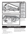
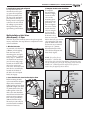
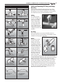
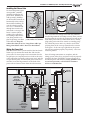
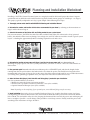
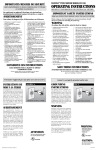
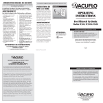
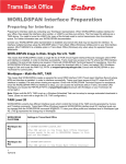
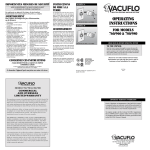
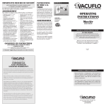
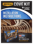
NEW CONSTRUCTION
planning
&
installing
Planning and Installing VACUFLO ® Built-in Central
Vacuum Systems in New Construction
2
Table of Contents
Planning a VACUFLO System Layout
Inlet Valve Location.....................................................................................................3
How to Measure Hose Reach ...................................................................................3
Power Unit and Exhaust Location .........................................................................3-4
Selecting a Power Unit ..............................................................................................4
PVC Tube Location .....................................................................................................4
Longest Tubing Runs ................................................................................................4
Installation of a VACUFLO System
Installing Inlet Valves ..............................................................................................5-8
Wall Installation of Inlet Valves (Before Drywall) – 4 Steps .................................5-6
Wall Installation of Inlet Valves (After Drywall) – 3 Steps .......................................7
Utility Valve Installation ...........................................................................................8
Floor Installation of Inlet Valves ...............................................................................8
Automatic Dustpan Option ......................................................................................8
Installing the Tubing System...................................................................................8-9
Important Installation Rules .....................................................................................9
Cutting and Cementing PVC Tubing and Fittings ...................................................9
Installing the Power Unit.....................................................................................10-11
Mounting the Power Unit .......................................................................................10
Electrical Requirements and Grounding Instructions ............................................10
Installing the Exhaust Line ..................................................................................... 11
Wiring the Power Unit ............................................................................................ 11
Planning and Installation Worksheet ...........................................................12
Tools of the Trade
Before starting any installation project, it is important to have the following recommended tools:
•
•
•
•
•
½” (13mm) right angle drill, or a
½” (13mm) drill with ½” (13mm)
by 90 drill chuck attachment
2 9/16” (65.1mm) diameter hole
cutter such as a Milwaukee Self
Feed Bit - 48-25-2561
¼” (6.4mm) diameter masonry
drill bit
Wire connectors - correct size for
#18-2 (1.00mm) wire
2” PVC tubing cutter
•
•
•
•
•
•
•
•
•
•
Hacksaw, with 18 teeth per
inch blade
Phillips head screwdriver
Flathead screwdriver
Hammer
Tape measure
Side cutters
Flashlight
Adhesive
Wire coat hanger
Clean cloth and rags
•
•
•
•
•
•
•
•
•
Utility knife or coarse
sandpaper
Tape or clips to secure
wire to tubing
PVC solvent
6’ or 8’ Ladder
Drywall Saw
Stud Finder
Cordless Drill
100’ Extension Cord
Reciprocating Saw
Planning a VACUFLO System Layout
3
Proper planning and installation of the VACUFLO System is the key to maximum
performance of the completed VACUFLO System. It is important to thoroughly
review and be familiar with this manual, which details the planning and installation
of VACUFLO True Cyclonic® and Filtered Cyclonic™ Systems.
Planning a VACUFLO System Layout
The planning process for the VACUFLO System can be categorized into three steps.
1. Inlet Valve Location – Be familiar with the house layout or blueprint to determine inlet valve locations.
2. Power Unit and Exhaust Location – Determine the best location for the power unit and exhaust.
3. PVC Tube Location – Plan a detailed path for the 2” PVC tube runs.
Inlet Valve Location
Correct inlet valve placement allows the 30-foot hose to
reach every corner of the house (including closets, ceilings, walls and drapes), while going around all furniture.
Inlet valves are typically located on inside walls, hallways, near doors and archways, and the bottoms of stairs
– avoid areas behind doors or furniture. Valves can also
be installed in the floor, if wall space is limited. Garage
inlet valves should be placed close to the large garage
door so vehicles, campers or boats do not need to be
pulled into the garage to clean them. Automatic dustpans
can also be considered for kitchens and mud rooms.
How to Measure Hose Reach
Planning inlet valve locations can be done by measuring with a 25-foot piece of string, tape measure, or the
actual hose itself, to determine reach of the hose – work
from the far corners of the room towards the center. The
objective is to provide maximum cleaning coverage with
POWER
UNIT
BEDRM
BEDRM
a minimum number of inlet valves. Typically the appropriate number of inlet valves needed can be calculated
by dividing a home’s total square footage by 600 (if a
30-foot hose is being used).
Power Unit and Exhaust Location
If the power unit location is specified in original layout
plans, review and determine whether it is actually the
best location.
The Power Unit should be located:
• in a remote area (i.e. basement, garage, utility room) –
never in an attic. Closet installations can be considered
if there is adequate ventilation such as louvered doors.
• on a dedicated circuit.
• away from heat-producing appliances (i.e. water
heaters, dryers, furnaces).
• on an exterior wall (preferably) to run the exhaust
line outdoors, with a maximum length of 30 feet.
BEDRM
LIVING
ROOM
HALL
GARAGE
KITCHEN
This floor plan shows the optimum location of three inlet valves and the 30-foot cleaning radius of each.
When planning the
exhaust line for the
VACUFLO True Cyclonic
System, it is important to
avoid patios, windows
and entryways. Exhaust
lines should be kept as
short as possible and
should not exceed 30 feet.
Do not vent into any concealed space of a building
or structure, such as
a wall, ceiling or attic.
(See the illustrations on
Page 5 for typical power
unit and exhaust locations
for a home.)
4
Planning a VACUFLO System Layout
Selecting a Power Unit
Selecting the proper power unit is critical to the
overall performance of a system. The System
Capabilities Chart (at right) identifies the recommended power unit based on the size of a home,
longest run of tubing, and the number of inlet
valves. These figures are estimates, and need to
be used with the actual tube layout and valve
placement.
System Capabilities
Use these figures as a guideline when planning a VACUFLO system.
Home
Size in
Sq. Ft.
Recommended # Model Model Model Model Model Model Model Model Model
of Inlets FC300 260 FC550 466Q FC650 566Q 760 FC1550 960
1,500
2
X
X
2,000
3
X
X
2,500
4
X
X
PVC Tube Location
3,000
5
Planning the most efficient tube path (from
power unit to inlet valves) will insure maximum
airflow at the inlet valves. The main trunk line
should run from the farthest inlet valve to the
power unit, with branch lines running to each
individual inlet valve. Tubing can be installed
in partitions, crawl spaces, under or between
floor joists, on the face of walls or columns in
the basement, or in attics. If tubing is placed in
attics, insulation should be laid over the tubing
to reduce the possibility of condensation (moisture) forming inside the tubing. For optimal
airflow, both the trunk and branch lines should
be as straight as possible using a minimal
amount of elbows (see illustration below).
3,500
Thorough tube path planning will save time and
effort. Check the proposed tubing path plans for
possible obstructions (i.e. heating ducts, plumbing) or problem areas, and adjust inlet valve
locations if necessary.
Longest Tubing Runs
The length of tubing running from the exhaust
location (including the length of tubing used
for the exhaust) to the furthest inlet valve from
the power unit, should be no longer than that
recommended in the System Capabilities Chart
(right). Excessively long tubing runs can affect
performance.
X
X
X
6
X
X
4,000
7
X
X
4,500
8
X
X
X
X
5,000
9
X
X
X
X
5,500
10
X
X
6,000
10
X
X
6,500
11
X
X
7,000
12
X
X
X
X
X
7,500
13
X
X
X
X
X
8,000
14
X
X
X
X
X
9,000
15
X
X
X
10,000
17
X
X
X
11,000
19
X
X
X
12,000
20
X
X
X
15,000
25
X
X
17,000
28
X
X
18,000
30
X
X
Yes
No
No-Vent Option
Yes
No
Yes
No
Yes
No
No
Longest Run of Tubing 100 ft. 125 ft. 150 ft. 150 ft. 175 ft. 175 ft. 200 ft. 250 ft. 250 ft.
45° ELBOWS
45° STREET
ELBOW
TEE ADAPTER
DROP
OBSTRUCT
ION
90° TY SET AT
45° TO HORIZONTAL
45° Y
SLIP COUPLING
OR STOP COUPLING
90° ELBOW
45° Y
45° ELBOWS
TRUNK LI
NE
45° Y
90° STREET
ELBOW
When lines come from
both ends toward center
use this arrangment
TO P
O
UN
WER
IT
SHORT PC. TUBING
45° ELBOW
90° ELBOW
90° TY
#18-2
(1.00mm)
Wire
BRANCH LINE
RISER
90° ELBOW
90° ADAPTER ELBOW
Planning a VACUFLO System Layout
5
Tubing Tips
When planning your
VACUFLO system
layout, it is important
to remember that:
• Approximately 20
feet of tubing is
required for each
inlet valve location.
EXHAUST
LOCATE POWER UNIT IN
UTILITY ROOM OR
BASEMENT
INLET VALVE
BRANCH LINES
Typical power unit and exhaust locations for a home with a basement or crawlspace. The trunk line is run
in the basement or crawlspace, below the floor joists.
• The straighter the
tube run, the greater
the airflow (suction)
to the hose.
• Using the least
amount of bends or
elbows in a run,
reduces the chance
of clogging.
NOTE: Exterior exhausting
is required for VACUFLO
True Cyclonic units, but is
optional for Filtered Cyclonic
power units.
INLET VALVE
BRANCH LINES
EXHAUST
LOCATE POWER UNIT IN
UTILITY ROOM
Typical power unit and exhaust locations for a slab-style home – trunk line is run in the attic.
Installation of a VACUFLO System
Installing Inlet Valves
Wall Installation of Inlet Valves (Before Drywall)
Several techniques are used when installing inlet valves
in new construction homes:
• Wall Installation
- Before Drywall
- After Drywall
• Utility Valve Installation (used in basements,
garages or where tubing is exposed)
• Floor Installation (used occasionally when floor
plan or construction dictates)
When installing the system in new construction, vertical tube lines and low-voltage wiring for the inlet
valves must be roughed in while the house is still in the
framing stage. Preferably, the following steps should be
completed after the house has been wired and plumbed,
but before the drywall is installed.
6
Installation of a VACUFLO System – Installing Inlet Valves
Wall Installation of Inlet Valves
(Before Drywall) – 4 Steps
1. Determine inlet valve locations
Inlet valves are typically located between studs in
hallways or under light switches, but away from
plumbing, wiring and heat ducts. The minimum stud
depth to accept the adapter elbow clearance is 2-¾”
(70mm). For aesthetic purposes, the height of inlet
valves should be consistent and installed at the same
height as electrical outlets.
Once the exact location of the inlet valves has been
determined, a pilot hole should be drilled at a point on
the floor directly below the vertical center of the desired
location (see illustration below). Insert a wire into the
pilot hole (the straight section of a coat hanger makes a
good pilot hole probe), and check from the floor below
that the wire does not interfere with any cold air returns.
MIN.
STUD
DEPTH:
2³⁄₄" Dia.
(70mm)
If no obstructions are evident, drill a 2-9/16” (65.1 mm)
diameter hole in the center of the sole plate next to the
stud. To avoid weakening the floor joists, be sure to stay
clear of areas where electrical and plumbing holes have
already been drilled. Also, check the electrical codes in
your area for any specific low-voltage codes.
2. Install the adapter elbow
Attach a 90° adapter
elbow to the tubing by
applying adhesive to the
outside of the tubing
only – never put adhesive on the inside of the
elbow (pictured at right).
Twist the tubing to create
a tight seal and wipe off
the excess glue.
A sharp 90° adapter elbow
is installed behind each
inlet valve to help prevent
large items from entering the tube system and causing
obstructions. Never use short 90º’s in the tubing
system except behind mounting plates.
3. Attach the mounting plate
and run wire
Attach the mounting plate
to the adapter elbow with
the plaster guard tabs
facing forward, and place
the tubing through the
hole – leave 2” (51mm)
extending below hole
to ensure the tubes will
reach one another. Screw
the mounting plate to
the front of the stud with
the adapter elbow next
to the stud (pictured at
left). Bring 10” (254mm)
of low-voltage wire
through the top oval hole
of the mounting plate and
double it back into the
adapter elbow. Also, allow
enough wire to dangle
through the sole plate
hole to later connect to the
truck line.
CENTER
CENTER
VALVE
HEIGHT
VALVE
HEIGHT
WITH
RECEPTACLES
WITHINRECEPTACLES
THE ROOM
IN THE
ROOM
OR
AS DESIRED
OR AS DESIRED
2¹⁄₄" to 2¹⁄₂" Dia.
(57-63mm)
DRILL PILOT HOLE
2¹⁄₂"
(64mm)
WIRE THROUGH
PILOT HOLE
SOLE PLATE
Nail Guard
Installation of a VACUFLO System – Installing Inlet Valves
4. Install plaster guard and nail guards
To help locate the valve
after the drywall is put
up, press the red plaster
guard insert firmly into
the face of the mounting
plate between the tabs.
Finally, install a nail guard
at the base of each side of
the tubing to prevent the
tubing from being damaged during construction.
FINISH
WALL
TO
HERE
VACUFLO
BUILT-IN CLEANING SYSTEM
Wall Installation of Inlet Valves
(After Drywall) – 3 Steps
After the drywall is finished, remove the plaster guard
inserts, and follow the steps below to complete the inlet
valve installation.
1. Wire the inlet valve
As pictured, take the #18-2
(1.00mm) wire dangling
from the front of the
mounting plate and split
it apart at least 1” (25mm).
Next, strip 3⁄ 8” (10mm) of
insulation from each wire
(use the wire strip gauge
located on the back of the
inlet valve to measure
each wire). Insert the wires
into the two switch holes
located on the back of
the inlet valve and push
firmly to engage.
2. Insert the inlet valve stem into the adapter elbow
Before inserting the inlet
valve stem into the adapter
elbow, make certain the
rubber gasket seal is in place
(pictured at right). For walls
¼” (6mm) thick or less, the
rubber gasket seal on the
inlet valve stem should be
moved forward to the front
groove to insure a proper
seal. A slot is provided 3⁄ 8”
(10mm) from the end of
the stem so it can easily be
sawed off with a standard
hacksaw if necessary.
7
3. Complete the inlet valve installation
To complete
the installation
(shown at right),
secure the inlet
valve in the
mounting plate
with four screws
(provided) – do
not over-tighten
the screws. Make
certain the inlet
valve is straight
and covers the
hole on all sides.
If the inlet valve
does not cover the
hole in the wall, use an inlet
valve trim plate. The trim
plate fits behind the valve
and covers any oversized
hole up to ½” (13mm).
When finished, the inlet
valve lid should open and
close freely (right).
NOTE: If a wall or floor is
more than 1” (25mm) thick,
use an inlet valve extension (Part #5018). Shorten the extension as necessary for a precise fit. The flange on the extension
should be ¼” (6mm) beyond the surface (wall or floor) to
insure valve fits properly (shown below).
WALL OR
FLOOR SURFACE
OVER 1" (25mm)
THICK
MOUNTING
PLATE
90°
ADAPTER
ELBOW
#18-2
(1.00mm)
WIRE
TUBE
EXTENSION
INLET
VALVE
8
Installation of a VACUFLO System – Installing Inlet Valves
TOP OF VALVE
SLOT FOR WIRE
USE ¹⁄₈" (3mm)
ALLEN WRENCH
TO MOUNT
VALVE ON
SCREW
³⁄₄"GAUGE
(19mm)
2 ³⁄₈"
(60mm)
³⁄₄"
(19mm)
LOCKED
POSITION
SPACE
FOR WIRE
CONNECTIONS
SLOTS FOR
STRAP MOUNTING
ON POST
WALL SURFACE
and use, the inlet valve should open to
the left (facing the wall). If the floor is
more than 1” (25mm) thick, use an inlet
valve stem extension.
Automatic Dustpan Option
VACUFLO’s automatic dustpans can be
installed with any new or existing central
vacuum system. Automatic dustpans
are typically installed in areas requiring frequent cleanups or sweeping, such
as kitchens, laundry rooms, garages or
workshops. The flush-mounted design
is easy to install beneath all styles of
cabinets (shown below), in baseboards, or
at the base of a wall, making them accessible but barely noticeable.
Utility Valve Installation
A utility valve (shown above) is used in basements,
garages, and other areas where tubing is exposed. To
install, put the screw provided into the wall (using an
anchor if necessary) until it protrudes ¾” (19mm). For
an accurate measurement, check the ¾” (19mm) protrusion with the gauge located on the back of the valve.
Connect the low-voltage wire leads in the valve and
push the connections into the space provided. Next,
change the valve to the unlocked position by placing an
1 ⁄ 8” (3mm) allen wrench over the screw and turning it to
the locked (“L”) position. If not snug, remove the valve
and adjust the screw slightly.
Installing the Tubing System
Floor Installation of Inlet Valves
Although inlet valves are typically installed in walls,
occasionally one must be installed in the floor. When
this occurs, the inlet valve should be placed about 2”
(51mm) from the wall in a low-traffic area. As with wall
installations, drill a small pilot hole and make sure the
location is clear of any obstructions (Step 1 on Page 6).
Next, cut a hole 2-¼” (57mm) wide by 3-¾” (95mm)
long. After checking for obstructions and cutting the
inlet valve hole, attach the mounting plate from below
to the 90° adapter elbow and assemble the inlet valve as
described on Page 7 and shown below. For easier access
INLET VALVE
FLOOR
MOUNTING PLATE
TUBE LINE
90° ADAPTER ELBOW
JOIST
#18-2 (1.00mm)
WIRE
Once the inlet valves are installed, roughing in the
tubing system begins. Start with the most distant inlet
valve and extend the trunk line towards the power unit.
Connect the branch lines to the trunk with 90° TYs,
making sure to maintain a directional flow towards the
power unit. As with the trunk line, branch lines should
be kept as straight as possible to maximize the airflow
that reaches the hose. Avoid creating tight corners in
the tube run by using 45° fittings instead of 90° fittings
whenever possible. Always run a branch line out of the
side or top of the trunk line. NEVER drop a branch line
directly out of the bottom of a trunk line - this creates a
pocket for dirt to accumulate in.
Low-voltage wire #18-2 (1.00mm) follows the tubing
from each inlet valve to and along the trunk line. Therefore at each branch or TY, junctions or splices are made
using wire connectors (observe local code). To secure the
wire along the tube run, tape it to the tubing or staple it
to the joists. Connect the wires to the low-voltage terminals located at the power unit.
Installation of a VACUFLO System – Installing the Tubing System
Important Installation Rules
CORRECT
WRONG
9
Cutting and Cementing PVC Tubing and Fittings
Measuring
Measurements should be taken from the base of the
pipe-stop on the inside of the fitting hub when sizing
the tubing. As each section of tubing is cut it should be
dry fitted before the next measurement is taken.
Cutting
Assemble TYs to provide
smooth airflow to power unit.
Improper installation causes
poor airflow.
Assemble TYs so that dirt enters
trunk line from side or top.
Gravity causes dirt to fall down
the wrong tube.
The tubing should
be cut as straight and
square as possible. It
is best to use a tube
cutter or deburring
tool. All rough edges
should be removed
with a deburring tool,
utility knife or coarse
sandpaper (inside and
outside).
Dry fitting
Airflow does not conflict with
proper installation.
Quick Clip
Leave slack in wires at the
connection and clip or tape in place.
A proper installation provides
good airflow.
Improper installation causes
a conflict in airflow.
WIRE
CONNECTIONS
STRAINED
Strained wire connections
may pull apart.
Poor airflow results from
improper installation.
CENTER LINE
Drilling in the center of beams
and rafters keep them strong.
Long 90˚ Elbows
90˚ Long elbows provide
efficient overflow
Drilling off center weakens
beams and rafters.
Short 90˚ Elbows
90˚ Short elbows ar NOT
interchangeable with
90˚ long elbows
Once all the pieces are cut, they should be dry fit to
check for correct fit. The markings on the fittings can be
utilized to assure proper alignment.
Gluing
PVC solvent cement
actually welds the
fitting to the tubing.
A chemical reaction
permanently joins the
molecules from each
surface to produce an
airtight seal. Before
cementing both the
tubing and the fitting,
they must be free of
PVC burrs, dirt and
grime. The components should be wiped with a clean cloth if necessary.
Cement should be applied to the outside of the tubing
only (pictured above). Never apply adhesive to the
inside of the fitting – this causes cement to accumulate
inside, which reduces airflow and could cause a clog.
The tubing should be inserted all the way into the fitting and twisted a quarter turn to evenly distribute the
cement. All excess cement should be removed with a
rag. The glue should be allowed several hours to set
before the vacuum system is used.
10
Installation of a VACUFLO System – Installing the Power Unit
Installing the Power Unit
When installing VACUFLO Twin Motor Power Units,
refer to the specific installation instructions shipped
with the product. For all other VACUFLO Power Units,
use the following instructions.
NOTE: VACUFLO True Cyclonic power units must be vented
outside. However, venting is optional when installing VACUFLO Filtered Cyclonic units. To ensure the quietest performance,
mufflers are recommended for all VACUFLO power units.
To mount on a masonry wall, use the wall-mounting
bracket as a template to locate and mark two holes on
a mortar joint or on the surface of a cement block. Drill
the two marked holes 1” inch (25mm) deep using a ¼”
(6.4mm) masonry drill bit. Securely mount the wall
bracket with anchors by inserting a ¼” (6.4mm) plastic
MARK THESE TWO
HOLES IN VERTICAL
MORTAR JOINT
AND THEN DRILL
Mounting the Power Unit
The power unit should be mounted on an exterior
wall, or within 30 feet of an exterior wall, to minimize
the length of the exhaust line. The unit should also be
mounted at a height about 6 feet (1.8m) from the floor to
the top of the mounting bracket, to provide easy access
to the dirt receptacle. To comply with UL standards, and
for proper ventilation and access, the wall-mounting
bracket must be at least 13-1⁄ 2” (343mm) from the ceiling,
14 “ (356mm) from a side wall, and at least 46” from the
floor (illustrated below).
13¹⁄₂" MINIMUM
TO CEILING
14" MINIMUM
TO WALL
46" MINIMUM
TO FLOOR
8"
MIN.
MARK THESE TWO
HOLES IN HORIZONTAL
MORTAR JOINT
AND THEN DRILL
Proper wall bracket mounting for vertical mortar joints (left) and for
horizontal mortar joints (right).
anchor in each hole and using two #12 by 1” (B5.5 x
25mm) sheet metal screws. If working in a framed or
drywalled area, position the wall-mounting bracket on
a stud and secure with two #14 by 1-½” (B6.3 x 38mm)
screws through the two vertical holes. Once the mounting brackets are properly installed (as shown above) and
secured, hang the power unit.
Electrical Requirements and Grounding Instructions
VACUFLO power units
operate on a nominal
120-volt circuit, and come
GROUNDING
OUTLET
equipped with a power
supply cord that has an
equipment-grounding
conductor and grounding plug. To reduce the
GROUNDING
risk of electrical shock (if
PIN
a unit should malfunction
or break down), the power unit must be plugged into
a properly grounded electrical outlet on a dedicated
circuit that complies with all local codes and ordinances.
Make sure the power unit is connected to an outlet
having the same configuration as the plug – no adapter
should be used. The electrical outlet must be within 5
feet of the mounting bracket, but no closer than 8 inches.
Warning: Improper connection of the equipmentgrounding conductor can result in a risk of electrical
shock. If there is any doubt as to whether the outlet is
properly grounded, check with a qualified electrician
or service person if you are in doubt. Do not modify the
plug provided. If the plug does not fit the outlet, have a
proper outlet installed by a qualified electrician.
Installation of a VACUFLO System – Installing the Power Unit
11
Installing the Exhaust Line
To ensure the quietest operEXHAUST
ation possible, a muffler
VENT CAP
OUTSIDE
should be installed on all
power units. (Mufflers are
EXTERIOR WALL
sold separately.) Mufflers
can be installed vertically or
horizontally in the exhaust
line inside the building. To
MUFFLER
vent the exhaust outside,
cut a 2 9/16” diameter hole
through the exterior wall
and attach a vent cap to the
house’s exterior (shown
at right). Next, glue the 2”
PVC tubing to the exhaust
To ensure the quietest operation
vent, being careful not to
glue the pivoting vent door possible, mufflers are recommended.
to the tube end. Keep the
exhaust line short, 30’ or less. Long elbows add 4’ per
fitting, short elbows add 8’. Don’t use short elbows.
Wiring the Power Unit
With the balance of the system installed, the final installation step is to connect the intake line and wire the
power unit. To ensure proper wire connections that do
not pull apart, it is important to leave slack in the wires
at the connection (especially at the power unit), and clip
or tape them in place. To connect the power unit valve
switches, locate the flag terminals on the back of the
power unit and remove them from the tab connectors.
Next, insert the low-voltage wires from the trunk line
into the flag terminals and crimp securely. Then, reinsert
the flag terminals onto the tab connectors located on the
back of the power unit (see illustration above). Finally,
plug in the power unit to be certain it is running properly. While the power unit is on, check to see that the
pivoting door on the vent cap (located on the exterior
wall) opens – if the vent cap is glued shut, the power
unit will not perform properly. No polarity - wires connected in parallel.
Once all wiring connections are complete, and the
tubing system, inlet valves and power unit are properly
installed, the entire VACUFLO system will operate at
maximum power and efficiency. If any problems occur
or you have questions, call VACUFLO Customer
Service at 1-800-822-8356.
MIN. 13¹⁄₂"
(343 mm)
FROM CEILING
TO TOP OF
WALL BRACKET
INTAKE
EXHAUST
90º
STREET
ELBOW
*MUFFLER
OUTSIDE
VENT CAP
90º
STREET
ELBOW
OUTSIDE
WALL
CLAMPS
UNIT CUT
AWAY TO
SHOW WALL
BRACKET
90º TY
UTILITY
VALVE
OPTIONAL
MIN. 14"
(356 mm)
FROM SIDE WALL
TO CENTER
OF UNIT
*Mufflers are an optional accessory.
FRONT VIEW
Proper installation of the power unit and exhaust line.
SIDE VIEW
Planning and Installation Worksheet
Installing a VACUFLO Central Vacuum System is a straight forward Do-It-Yourself project that doesn’t require
specialized tools or skills (the tools needed are those typically found in most garages or workshops – see Page 2).
This project, typically completed in one day, is quite simple when following these steps:
1. Thoroughly review and be familiar with VACUFLO’S Planning and Installation Manual.
2. Determine the number and location of inlet valves recommended for your home by referring to the instructions on
Page 3 and the chart on Page 4.
3. Calculate the number of Inlet Valves Kits and Tubing needed for your system layout.
For your convenience, VACUFLO has Inlet Valve Kits available with either one or three inlet valves (pictured
below), that include all the necessary fittings, low-voltage wire and PVC adhesive needed to install a typical system
layout – excluding the approximately 20 feet of tubing required for each inlet valve.
One inlet valve kit
Kit for three inlet valves
4. Determine the location of your power unit (Page 3) and the size of your power unit (see chart on Page 4).
Matching the proper power unit to the system performance you desire is critical – there are several models to
choose from.
5. Plan your tube path. Remember that the most efficient path is a STRAIGHT path, and that the length of tube
running from the exhaust location to the furthest inlet valve from the power unit should be no longer than that
recommended in the Chart on Page 4. Also, make sure to check the proposed tube path for any possible obstructions
(i.e. heating ducts, plumbing) or problem areas, and adjust the inlet valve locations if necessary.
6. Order the Power Unit (Step 4), Inlet Valve Kits and Tubing (Step 3) needed for your installation.
It is also recommended that you order a:
• Muffler (to ensure the quietest operation possible)
• Exhaust Vent Cap (for the exterior of your home – two styles available)
• Optional Automatic Dustpan (two styles available)
Note: Depending on the complexity of your system layout, some additional fittings may be necessary.
7. Begin installation. Once inlet valves are installed (reference Pages 5-8), rough in the tubing system (see Pages
8-9) beginning with the most distant inlet valve and extend the trunk line to the power unit. Connect the branch
lines with 90º TYs (included in inlet valve kit), keeping the directional flow towards the power unit and keeping all
lines as straight as possible – use 45º fittings when possible to avoid sharp corners. Finally, install the power unit
according to the instructions on Pages 10 and 11.
H-P PRODUCTS, INC. • Louisville, Ohio 44641 • 1-800-822-8356 • Fax 330-875-7584 • www.vacuflo.com • HVS-828 Rev.9/05