1
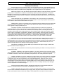
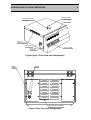
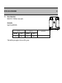
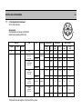
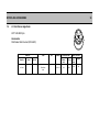
Instruction Manual HARRIER 15/80 HARRIER 18/80 CENTRIFUGE READ BEFORE USE! Models:- MSB080.CX1.1 MSB080.CX1.5 MSB080.CR1.K MSB080.CR1.H MSB080.CR2.H MSB080.CR2.K 71100-1378-11 0206 MSE (UK) Ltd Health and Safety at Work MSE (UK) Ltd is required under the Health and Safety at Work Act 1974 and other UK legislation as designers, manufacturers, suppliers and importers of articles for use at work to ensure that, as far as is reasonably practicable, articles which we design, produce, supply or import are safe and without risk to health. We are required to provide information on the safety and handling precautions to be observed when installing, operating, maintaining and servicing our products. Such advice is contained in this manual. We are also obliged to update this information should circumstances change and to operate a system to this end. We should also like to point out, however that you as users have an important responsibility in the provision and maintenance of safe working practices and conditions. Accordingly, we draw the following matters to your attention: 1. This apparatus should only be used as intended and within its design parameters by suitably qualified and trained personnel who have read and understood the relevant sections of this manual. 2. This manual should be readily available to such personnel at all times. 3. In addition to that which is written in the manual, normal common-sense safety precautions must be taken at all times to avoid the possibility of accidents. Particular care is required when working with apparatus at high temperature or pressure. 4. Installation, maintenance, repairs and servicing should only be carried out by an MSE (UK) Ltd approved engineer, and connection to electrical supplies should only be carried out by suitably trained personnel. TECHNICAL SUPPORT, WARRANTY SERVICE AND MAINTENANCE UK customers; if you are in any doubt whatsoever regarding the correct use of this apparatus, or if you require any technical data or assistance, please contact the MSE (UK) Ltd Technical Support Department at: MSE (UK) Ltd Worsley Bridge Road Lower Sydenham London SE26 5AZ Telephone Fax E-mail: Web Page: +44 (0) 870 609 4097 +44 (0) 208 650 8408 [email protected] www.mseuk.co.uk OVERSEAS CUSTOMERS: Should contact their local MSE (UK) Ltd Distributor, details can be found on our website. ELECTRICITY SUPPLIES: Voltage and frequency MSE (UK) Ltd electrical apparatus is offered and labelled for one, or for a choice of two or more voltage ranges and, where necessary, different frequencies of mains supply. MSE (UK) Ltd does not accept any responsibility for the operation of any such apparatus should it be connected to electricity supplies which are normally outside, or vary outside, the stated voltage and frequency values for which it is designed, nor for any consequential loss, damage or injury, howsoever caused. MSE (UK) Ltd WARRANTY Terms and Conditions We hope that you do not have the need to use the extensive warranty cover that MSE (UK) Ltd extends to you. However should you have a problem, our prompt response is greatly helped if you have filled in and posted the pre-paid Warranty Registration Card supplied with your new equipment. MSE (UK) Ltd gives a one-year warranty from the date of delivery. During this period, component parts proven to be defective in materials or workmanship will be repaired or replaced at our expense. Installation, commissioning and calibration are not covered by this warranty agreement. The MSE (UK) Ltd approved service agent must be contacted for warranty determination and direction prior to any work being carried out. These warranties are only applicable to new products, and not second hand nor refurbished products even if repaired by MSE (UK) Ltd. Any such products are covered by separate warranty terms and conditions which will be made available on request. Replacement or repair of component parts or equipment under this warranty shall not extend the warranty to either the equipment or the component part beyond the original one year warranty period unless agreed in writing by MSE (UK) Ltd. The above warranties are extended to the original purchaser upon full invoice payment. A purchase receipt or other proof of purchase may be required before warranty service will be performed. These warranties only cover failures due to defective workmanship which occur during the normal operation of the product by the original purchaser, and not failures which result from accident, misuse, abuse, neglect, mishandling, misapplication, alteration, faulty installation, electrical power fluctuations, dust, or other environmental extremes, modification or service other than by an approved service agent or following the written authority of the manufacturer, or damage that is attributable to acts of God. Expendable items such as motor brushes, door seals, lid seals, "O" rings or lamps are excluded. MSE (UK) Ltd., or its approved service agent, reserves the right to repair defective equipment on the premises of the customer, or at a service station, at the sole discretion of MSE (UK) Ltd or their approved agent. In the event of return to an approved service centre the customer is responsible for the safe packaging of the instrument and notification to the service centre. Neither MSE (UK) Ltd nor its agents are responsible for any damage occurring during shipment. Specification and Material Changes: MSE (UK) Ltd reserves the right to supply our latest and improved models at time of shipment. Taxes: The prices quoted do not include any taxes imposed by the State or Country in which the purchase was made. Installation: Installation of all equipment shall be by, and at the expense of the purchaser unless stated otherwise. Access to the site, and the provision of required utilities e.g. Power, water and drainage to suitable connections, will be the responsibility of the purchaser, and at the purchaser's expense. Limitation of liability: In no event, whether as a result of breach of contract or warranty, shall MSE (UK) Ltd be liable for any consequential or incidental damages including, but not limited to, loss of profit or revenues, loss of use of the equipment or any associated equipment, down time costs, costs of substitute equipment, costs of labour, costs due to delays or claims of purchaser's own customers for such damages. The purchaser agrees to indemnify MSE (UK) Ltd and to hold them harmless from any and all liability, claims, demands, actions, suits, expenses or costs, including attorney's fees relating to such consequential or incidental damages. All expressed and implied warranties, including the warranties of merchantable quality and fitness for a particular purpose, are limited to the application period of one year. Validity: Legal rights vary from country to country and states within countries, so some or all of the exclusions or limitations listed above may not apply, but if any part of these conditions shall be found to be unenforceable it shall not affect the validity or enforceability of the remainder of the conditions. CONTENTS 4 ELECTRICITY SUPPLY Before connecting this apparatus to the electricity supply, check the information given on the rating plate and ensure that; A) Your supply is single phase AC (alternating current) of the stated frequency with neutral nominally at earth potential. B) Your supply voltage is within the stated range. C) The current rating is within the capacity of your outlet. D) Your plug or electricity supply circuit is fitted with a suitable fuse. Fuse rating 230v 13 amp 110v - 120v 15 amp WARNING! This apparatus must be earthed. The wires in the mains lead are coloured in accordance with the following code; Live Neutral Earth 230v Brown Blue Green and Yellow 110v - 120v Black White Green Connect the wires to a non-reversible 3-pin plug as follows: Green and Yellow or Green to terminal marked E (Earth), G (Ground), coloured Green or Green and Yellow or marked with the Earth symbol. Blue or white wire to terminal marked N (Neutral) or Common or coloured Blue. Brown or black wire to terminal marked L (Live) or Phase or coloured brown. Note: 110v - 120v installations to comply with National and State Wiring Codes. IMPORTANT Consult an electrician if in any doubt or if your supply system has any of the following: No earth A colour code different from above Reversible plugs Supply and return leads that are both above earth potential. CONTENTS 5 1. INTRODUCTION TO YOUR CENTRIFUGE 7 1.1 Specifications ........................................................................................ 10 2. INSTALLATION ................................................................................................... 12 2.1 Connecting the power supply .............................................................. 13 2.2 Centrifuge restraint ............................................................................... 13 2.3 Accessories supplied with each centrifuge........................................ 13 3. GOOD OPERATOR PRACTICE ......................................................................... 14 3.1 Spillages ................................................................................................ 14 3.2 Materials with specific gravity in excess of 1.2 .................................. 14 3.3 Corrosive materials............................................................................... 14 3.4 Infective samples .................................................................................. 15 3.5 Servicing ................................................................................................ 15 4. THE DISPLAY AND CONTROL PANEL............................................................. 16 5. HOW TO USE YOUR HARRIER CENTRIFUGE ................................................ 17 5.1 Opening the lid ...................................................................................... 17 5.2 Rotors and accessories........................................................................ 17 5.3 Fitting the rotor...................................................................................... 18 5.4 Loading the rotor................................................................................... 18 5.5 Balancing the rotor ............................................................................... 19 5.6 Removing the rotor ............................................................................... 19 5.7 Closing the lid........................................................................................ 19 5.8 Parameter entry ..................................................................................... 19 5.8.1 Entering run time.......................................................................... 19 5.8.2 Time hold ...................................................................................... 20 5.8.3 Entering speed (RPM).................................................................. 20 5.8.4 Entering an RCF value ................................................................. 20 5.8.5 Entering Temperature.................................................................. 20 5.8.6 Precool .......................................................................................... 20 5.8.7 Entering acceleration and brake rate......................................... 21 5.9 Starting the run...................................................................................... 21 5.10 Code Key................................................................................................ 21 5.11 Manual termination of run. ................................................................... 21 5.12 Opening the lid if there is a power failure ........................................... 22 6. ERROR MESSAGES........................................................................................... 23 6.1 Error message table.............................................................................. 24 CONTENTS 6 7. ROTORS AND ACCESSORIES.......................................................................... 30 7.1 4 X 200 Windshield Swing Out Rotor - for use with Harrier 18/80 refrigerated only............................................................................................. 30 4 x 200 Swing out rotor - for use with Harrier 15/80 only........................... 31 7.3 4 x 200 swing out rotor - for use with Harrier 15/80 only................... 32 7.4 4 x 200 Swing out rotor - for use with Harrier 15/80 only .................. 33 7.5 Microtitration Rotor ............................................................................... 34 7.6 6 X 50 Angle Rotor ................................................................................ 35 6 X 50 Angle Rotor Continued ...................................................................... 36 7.8 12 X 15 Angle Rotor .............................................................................. 37 7.9 4 X 50ml Falcon Angle Rotor................................................................ 38 7.10 24 X 1.5ml Angle Rotor ......................................................................... 39 7.11 24 X 1.5ml Sealed Angle Rotor............................................................. 40 8. MAINTENANCE................................................................................................... 41 8.1 Cleanliness ............................................................................................ 41 8.2 Drive shaft.............................................................................................. 41 8.3 Rotors and buckets............................................................................... 41 8.4 O-Rings .................................................................................................. 42 8.5 Sterilisation............................................................................................ 42 8.6 Disinfecting............................................................................................ 42 8.7 Lid seal................................................................................................... 42 8.8 Replacing the fuse ................................................................................ 43 9. PRODUCT DISPOSAL - ISO 14001 COMPLIANCE.......................................... 43 10. HOW TO OBTAIN SERVICE ON YOUR HARRIER CENTRIFUGE .................. 44 ILLUSTRATIONS 1. Figure 1 Front View (Refrigerated) ........................................................................ 8 2. Figure 2 Rear View (Refrigerated) ......................................................................... 8 3. Figure Figure 3 Front View (Non Refrigerated) .................................................... 9 4. Figure 4 Rear View (Non Refrigerated) ................................................................. 9 5. Figure 5 Recommended clearances....................................................................12 6. Figure 6 Suggested Restraint System ................................................................13 7. Figure 7 The display and control panel .............................................................. 16 8. Figure 8 The display on power-up....................................................................... 17 9. Figure 9 Tightening the rotor nut......................................................................... 18 10. Figure 10 Acceleration and brake rate curves .................................................. 21 11. Figure 11 Lid lock override method (viewed from front) ................................. 22 INTRODUCTION TO YOUR CENTRIFUGE 1. 7 INTRODUCTION TO YOUR CENTRIFUGE The HARRIER range of performance bench top centrifuges joins the well established range of MSE centrifuges. The entire MSE range of centrifuges has been designed to meet the present and future demands of routine research laboratories. A comprehensive range of rotors and accessories are available to accommodate the most commonly used centrifuge tubes and bottles. In the HARRIER range, MSE have utilised the best of current technology to produce the most advanced, safe and reliable instrument possible. Advanced design features include:• INTELLIGENT MICROPROCESSOR CONTROL • LED DISPLAY / TACTILE CONTROL PANEL • INVERTER CONTROLLED BRUSHLESS MOTOR • AUTOMATIC ROTOR IDENTIFICATION SYSTEM • LAST RUN RECALL • OVERSPEED PROTECTION • FULL LID INTERLOCK • IMBALANCE MONITOR • SELF DIAGNOSTIC DISPLAY • SIMPLE TO USE • EASY SERVICING • KEY PAD LOCK • *REFRIGERATION • *PRE COOL FACILTY * Harrier 18/80 Refrigerated only INTRODUCTION TO YOUR CENTRIFUGE 8 RELEASE HANDLE HOLE FOR EMERGENCY LID OPENING DISPLAY PANEL CO 5 4 3 2 1 6 MAINS SWITCH RC F E PR OL CO 9 0 DE CE 8 7 AIR INLET (DO NOT OBSTRUCT) EL A CCAK E BR E TIM LD HO CONTROL PANEL RATING LABEL (SERIAL No.) REFRIGERANT CHARGE LABEL Figure 1 Front View (Refrigerated) FUSE LABEL FUSES AIR OUT (DO NOT OBSTRUCT) Figure 2 Rear View (Refrigerated) INTRODUCTION TO YOUR CENTRIFUGE 9 RELEASE HANDLE HOLE FOR EMERGENCY LID OPENING DISPLAY PANEL CO 5 AIR INLET (DO NOT OBSTRUCT) 1 6 RC F 4 3 2 8 9 0 DE CE 7 CEL AC AKE BR E TIM LD HO MAINS SWITCH CONTROL PANEL RATING LABEL (SERIAL No.) Figure Figure 3 Front View (Non Refrigerated) FUSE LABEL FUSES AIR OUTLET LOUVRES Figure 4 Rear View (Non Refrigerated) INTRODUCTION TO YOUR CENTRIFUGE 1.1 10 Specifications Refrigerated Non Refrigerated Power supply options 120v 60Hz single phase 230v 50Hz single phase 120v 50/60Hz single phase 230v 50/60Hz single phase Power consumption at full load (Acceleration power shown in brackets) 120v - 2000 watts (3000 watts) 230v - 800 watts (1600 watts) 120v - 1020 watts (1500 watts) 230v - 420 watts (1050 watts) Time DISPLAY/RANGE 0 - 59 minutes 59 seconds 1 hour - 99 hours 59 minutes or Time Hold 1 hour - 99 hours 59 minutes or Time Hold Timing Accuracy 0.1 second 0.1 second Speed range up to 18,000 rpm up to 15,000 rpm Speed control accuracy ± 10 rpm ± 10 rpm Speed DISPLAY ± 20 rpm ± 20 rpm Speed SETTING increments 1 rpm 1 rpm RCF range up to 28975g up to 20154g RCF SETTING increments 1g 1g Temp range 0 to 40°C* _ Temp accuracy ± 2°C _ Pre cool -9 to ambient _ Acceleration rates 10 off 10 off Brake rates 10 off 10 off Dimensions Height 340 mm Width 670 mm Depth 580 mm (not including mains cable) Weight 65 kg Height 340 mm Width 470 mm Depth 580 mm (not including mains cable) Weight 41 kg Standard operating conditions Atmospheric pressure 950-1015 mbar (13.78 - 14.71 psi) Ambient temperature +10°C to +35°C Max. operating temperature +35°C Humidity up to 70% RH Atmospheric pressure 950-1015 mbar (13.78 - 14.71 psi) Ambient temperature +10°C to +35°C Max. operating temperature +35°C Humidity up to 70% RH *Temperatures lower than 0°C can be obtained, dependent on rotor, at maximum speed. INTRODUCTION TO YOUR CENTRIFUGE 11 The Harrier Centrifuge range are CE marked in line with required European Directives for Electromagnetic and Low Voltage Compatibility, see “Declaration of Conformity” for EC directive/standard used. 120v units designed for CSA approval to the following standards: CAN/CSA CAN/CSA C22.2 No. 1010.1-92 C22.2 No. 1010.2.020-94 INDEPENDENT SPEED SENSING - 120 volt Machines only To comply with certain USA standards the 120 volt machines are fitted with a small window in the cover. This permits independent speed check directly from the rotor with use of an optically coupled tachometer. GOOD OPERATOR PRACTICE 2. 12 INSTALLATION Remove the centrifuge from its packaging and place it on a rigid, level surface. DO NOT LIFT THE CENTRIFUGE BY IT'S LID. The location of the keyboard, display, air inlet, lid lock access hole, and the release handle are shown in Figure 1 on page 8. The location of the serial number label, power switch and fuses are shown in Figure 2 on the same page. IMPORTANT: THE ROTOR MUST NOT BE FITTED WHEN MOVING THE CENTRIFUGE OR DURING TRANSIT. Check that the available power supply corresponds to that stated on the rating plate located at the rear of the instrument. If the restraint kit (see “Centrifuge restraint”) is not used to secure the centrifuge on the bench then, it is the recommendation of BS EN61010-2-020 that a clearance of 300 mm is allowed around the base of the centrifuge when in the final operating position. NOTE: Laboratory management procedures should require that no person or any hazardous materials are within a 300mm boundary while the centrifuge is operating. Figure 5 Recommended clearances Note: 75mm if solid surface (i.e. wall) otherwise 300mm GOOD OPERATOR PRACTICE 2.1 13 Connecting the power supply 230v centrifuge - Connect the 3-core cable to a 3-pin plug, fitted with a 13 amp fuse. Brown wire to Live (L) terminal Blue wire to Neutral (N) terminal Yellow/Green wire to Earth (E) terminal NOTE: BS EN 61010-2-020 ‘Particular Requirements for Centrifuges’ states that a remote switch, preferably adjacent to the room exit is a requirement in case of unit malfunction. 120v centrifuge - supplied with fitted plug. 2.2 Centrifuge restraint A suggested restraint system (part number SG.66500.1214), which secures the centrifuge to a sound work surface, is shown in Figure 6. It consists of 4 anchor brackets, positioned at each corner of the centrifuge base, which are bolted or screwed to the work surface. Figure 6 Suggested Restraint System 2.3 Accessories supplied with each centrifuge Description Quantity Part No. Emergency over-ride key 1 76600.004 Guarantee card 120v/230v 1 71100.1052/958 Operating manual 1 71100.1378 Box spanner 1 96500.384AD GOOD OPERATOR PRACTICE 3. 14 GOOD OPERATOR PRACTICE Please read the following notes before attempting to operate the centrifuge. 3.1 Spillage In the event of a liquid spillage the affected surfaces should be cleaned immediately. The rotor and accessories should be removed for thorough cleaning. Regular cleaning of the centrifuge is highly recommended to avoid the build up of contaminants. 3.2 Materials with specific gravity in excess of 1.2 The maximum speed of each rotor is calculated on the basis of samples with a specific gravity of 1.2. If materials of a higher specific gravity are used, then the maximum rotor speed must be reduced according to the formula below. Where M = New maximum speed N = Normal maximum speed S = Specific gravity of sample 3.3 Corrosive materials Where particularly corrosive materials are to be centrifuged, the samples should be placed in sealed containers and all necessary precautions observed. The following list gives examples of corrosive materials used in laboratories. • Phenol/cresol/water • Chloroform/isoamyl alcohol • Salt solutions (especially ammonium sulphate) • Solutions of ammonium hydroxide and acidic solutions e.g. hydrochloric, trichoracetic and perchloric acids. Other materials may be equally corrosive, the user is responsible for checking the characteristics of substances used. NOTE: The following materials are prohibited: • Flammable or explosive materials • Materials which chemically interact vigorously GOOD OPERATOR PRACTICE 3.4 15 Infective samples Very special care is necessary when infective materials are to be centrifuged. Sealed containers should always be used. The caps should be double checked to ensure that they are not damaged and fit correctly prior to starting the centrifuge. After use containers and caps should be sterilised immediately using a non-corrosive method. NOTE: Sealed containers and related components are intended to be part of bio safety systems such as are specified in international and national bio safety guide lines, and cannot be relied on as the only means of safeguarding workers and the environment when handling pathogenic micro-organisms. 3.5 Servicing It is advisable to have this centrifuge serviced regularly by a competent engineer, preferably the manufacturer's representative, at least once per year. THE CONTROL PANEL 4. 16 THE DISPLAY AND CONTROL PANEL The displays and keys on the control panel are labelled as follows:1. Run time display 2. Speed/RCF display - when displaying RCF values a point will be displayed in the bottom right hand corner 3. *Temp display 4. Accel/brake rate display (Accel rate is only displayed when the value is set and while accelerating) 5. Status display 6. Run time key 7. Time hold key 8. Speed key 9. RCF key 10. *Temp key 11. *Pre cool key 12. Accel / brake rate key 13. Rotor start key 14. Rotor stop key 15. Numerical keys (for time, speed etc.) 16. Minus/code key 17. Cancel entry key *Applies to Refrigerated models only Figure 7 The display and control panel HOW TO USE YOUR HARRIER 18/80 5. 17 HOW TO USE YOUR HARRIER CENTRIFUGE Connect to the power supply. Press the power ON switch, -situated on the left hand side panel of the centrifuge (see Figures 1 & 3) - 0 = OFF, 1 = ON. The status display will become active and an audible signal will inform the user that the instrument is ready for use. On power up the centrifuge will display the values which were current when the instrument was last switched off. An example of the display is shown below. Figure 8 The display on power-up 5.1 Opening the lid To open the lid push back the release catch on the top of the unit. The lid is supported by a gas strut and will open automatically. 5.2 Rotors and accessories The tables in section Error! Reference source not found. list the range of rotors and accessories available for use with the Harrier centrifuge range. When using any of the alternative rotors it would be advisable to rotate the rotor through 90°, 180°, and 270° to it’s first location on the drive head to check for the quietist position when running at maximum speed. Mark the rotor label appropriately in line with the pre-printed dot on the drive head, Before fitting a rotor ensure that the drive head and rotor bore are clean. Pay particular attention to the pivot pins of the swing-out rotors and the pockets in angle rotors. HOW TO USE YOUR HARRIER 18/80 5.3 18 Fitting the rotor If the centrifuge has been supplied with a matched wind shielded rotor (MSB080.CR2.K and MSB080.CR2.H) ensure that when fitting the rotor the alignment marks (yellow dots) on the drive head and the rotor are lined up. Locate the rotor on the drive head and tighten the rotor nut firmly by using the spanner provided, while holding the rotor stationary. DO NOT RUN THE CENTRIFUGE WITHOUT A ROTOR BEING FITTED TO THE DRIVE SHAFT. FAILURE TO COMPLY WITH THIS REQUIREMENT WILL CAUSE AN ERROR TO BE DISPLAYED. Figure 9 Tightening the rotor nut 5.4 Loading the rotor Sealed rotors, buckets, cups and trunnions are supplied as matched, balanced assemblies. It is important that all components should be stored and used together. It is not necessary for all buckets to be loaded, provided that the loads are placed symmetrically around the rotor. THE ROTOR MUST ALWAYS BE USED WITH A FULL COMPLIMENT OF BUCKETS DO NOT RUN WINDSHIELDED ROTORS WITHOUT THEIR COVERS IN PLACE. FAILURE TO COMPLY WITH THIS REQUIREMENT COULD RESULT IN SERIOUS DAMAGE TO THE CENTRIFUGE. CARE MUST BE TAKEN TO PREVENT DISTORTION OF WINDSHIELDED ROTORS. LIFT THEM BY GRASPING THE ARMS OF ROTOR SPIDER AND NOT BY THE WINDSHIELD. WARNING: RIA ROTOR LOADINGS MUST BE EVENLY DISTRIBUTED ABOUT PIVOT POINT OF EACH CARRIER. SEE LEAFLET SUPPLIED WITH ROTOR DO NOT RUN THE RIA ROTOR WITHOUT THE CARRIERS IN PLACE. If using a swing-out rotor, check that all cups/buckets are correctly located on their pivot pins by ensuring that they swing freely. HOW TO USE YOUR HARRIER 18/80 19 Refer to the chapter headed “Good Operator Practice” on page 14 for centrifugation of samples with the following characteristics:Specific gravity in excess of 1.2 Corrosive materials Infective samples 5.5 Balancing the rotor The loads should be reasonably balanced, which, in most cases, means equalising the liquid levels by eye. In the swing out rotor do not exceed 5 grams between loads when fully or partially loaded. When loading trunnion carriers (Cat.No.34136.110 and buckets 43156.603) the following procedure should be adhered to:1) Weight group the buckets to within 5g. 2) Weight group the trunnion block and buckets as an assembly to within 5g. Failure to load the rotor carefully may trip the out-of-balance sensor, causing the instrument to stop, in this case the status display will show “IMBALNCE”. An unbalanced rotor will make the centrifuge vibrate and it will be noisy in operation. 5.6 Removing the rotor Open the lid. Remove all the buckets and trunnions. Using a suitable bar inserted through the hole in the spindle nut, unscrew and remove the spindle nut. Grip the rotor on opposite sides and lift it clear of the drive head. NEVER USE EXCESSIVE FORCE. 5.7 Closing the lid Once you have loaded the rotor close the lid and push it firmly down. You will hear a ‘click' this means that the lid has locked down securely. The status will read “READY” and the run may be started. 5.8 Parameter entry The current parameters are shown in the display windows. To start the machine with the current parameters press (start). To alter the parameters press the relevant keys as described below. The parameters can be changed in any order. 5.8.1 Entering run time To change the run time press the (time) key. The time display will flash, and the status will read “SET HOURS”. Enter the number of hours and press again. The status will now read “SET MINS”. Enter the number of minutes and press again. If zero hours was selected the status will read “ SET SEC”, enter the number of seconds and press again. The display will stop flashing and will read “READY”. If an error is made at any stage, press CE and re-enter the time. N.B. The maximum time that can be entered is 99 hours and 59 minutes or 99 minutes and 59 seconds. An error will be produced if the time entered is too great, i.e. a time greater than 59 seconds. HOW TO USE YOUR HARRIER 18/80 20 5.8.2 Time hold If the unit is not required to run to a specific time press the TIME HOLD key, the time display will read “hold”. To revert back to a timed run press time hold again. On time hold the unit will run for 99 hours 59 minutes before stopping. It can be manually stopped at any time by pressing the (stop) key. 5.8.3 Entering speed (RPM) To change the speed, press the (speed) key. The displayed speed will flash and status will read “SET SPEED”. Enter the required speed. If a mistake is made press CE, the display will clear and the new speed can be entered. Once the correct speed is entered press the key again, the display will stop flashing and the status will revert back to ”READY”. While the machine is running in RPM mode the RCF value can be displayed for 5 seconds by pressing the RCF key. 5.8.4 Entering an RCF value To change the RCF value press RCF. Speed/RCF display will flash and the status will read “SET RCF”. Enter the required RCF value. If a mistake is made press CE, the display will clear and the new RCF value can be entered. Once the correct RCF value is entered press the RCF key again, the display will stop flashing and the status will revert back to ”READY”. While the machine is running in RCF mode the RPM value can be displayed for 5 seconds by pressing the Speed key. N.B. Each rotor has a maximum speed (and RCF value). If the operator selects a value in excess of this the unit will reduce the value to the maximum limit once the rotor has been identified. 5.8.5 Entering Temperature To change the temperature press the (temperature) key. The displayed temperature will flash and the status will read “SET TEMP”. Enter the required temperature. If an error is made, press CE, the display will clear and the new temperature can be entered. Once the correct temperature is entered press the key again. The display will stop flashing and the status will revert to “READY”. 5.8.6 Pre-cool To pre-cool the rotor and samples, fit the rotor and load the samples as outlined in Section 5.4. Close the lid and press down firmly to engage the lid lock. Press the pre-cool key. The status display will read “PRECOOL”. HOW TO USE YOUR HARRIER 18/80 21 5.8.7 Entering acceleration and brake rate To change the acceleration and brake rate press the ACCEL/BRAKE key. The brake display will flash and read “SETACCEL”. Enter the acceleration rate and press ACCEL/BRAKE again. The display will read “SETBRAKE”. Enter the brake rate. If an error is made press CE and re-enter the value. Once the correct values have been entered press ACCEL/BRAKE again, and the display will stop flashing. The status will read “READY”. Figure 10 Acceleration and brake rate curves 5.9 Starting the run Ensure that the rotor is correctly loaded and fitted. Close the lid and press down firmly to engage the lid lock. Press the rotor start key. The display will now change to show actual values of speed, run time and brake rate. During the run the status display will read “ROTOR ID”. The status of the unit is ramp up at speed and stopping. At the end of the run an audible bleep will be heard. 5.10 Code Key The code key can be used to lock and unlock the key pad. To do this press the code key. The status will display “CODE” press 1, 2 & 3. The status will read “LOCKED”. When the keypad is locked only the Start and Stop keys will operate. The code key can also be used to change the language displayed in the status window. To do this press the code key followed by the appropriate code as shown below: 000 for English 001 for French 002 for German 5.11 004 for Portuguese 006 for Danish 007 for Turkish 008 for Hungarian 009 for Romanian 010 for Estonian Manual termination of run. At any time the run may be stopped by pressing the (STOP) key. HOW TO USE YOUR HARRIER 18/80 5.12 22 Opening the lid if there is a power failure It will not be possible to open the lid by the normal method of pushing the release handle if there is a power failure, or if the lid lock has been deliberately disabled by the control system for safety reasons. The procedure below should be followed in these circumstances:1. Switch the centrifuge OFF - WAIT 5 MINUTES TO ENSURE THE ROTOR HAS STOPPED. 2. Insert the emergency over-ride key into the small hole near the release handle, (see Figure 1 page 8). 3. Move the key as shown in Figure 11 below to move back the lid lock solenoid. 4. With the lid lock solenoid dis-engaged, push back the release handle and the lid will open normally. Figure 11 Lid lock override method (viewed from front) ERROR MESSAGES 6. 23 ERROR MESSAGES Any error message is intermittently displayed in the status display. The display is accompanied by an audible alarm. Refer to the error message table for a full explanation of each message and the correct course of action. IMPORTANT:- ENSURE THAT THE AIR INLET AND OUTLET ARE NOT OBSTRUCTED IN ANY WAY. Should the display show an error message which then cannot be cleared or re-occurs after clearing then the power supply should be disconnected and the service engineer called. ERROR MESSAGE TABLES 6.1 24 Error message table NOTE: If an error is not rectified by taking the suggested action, if it is erratic or persists without apparent cause, disconnect the power supply and contact the service engineer. ERROR MESSAGE EXPLANATION EFFECT ON MACHINE OPERATOR ACTION INVALID The parameter entered is not valid i.e. minutes >59 Machine will not run 1. Press CE to clear error 2. Re-enter parameter BAD ID Rotor has not been Machine will stop identified or rotor not fitted Error cannot be cancelled until motor has stopped turning 1. Press CE and open lid 2. Check rotor has been fitted 3. Remove rotor, clean drive head and top surface of motor 4. Clean and inspect rotor bore and underside of rotor BADROTOR Rotor identified should not Machine will stop be fitted to machine Error cannot be cancelled until motor has stopped turning 1. Check that the rotor is correct for the machine 2. Remove rotor, clean drive head and top surface of motor 3. Clean rotor bore and underside of rotor 4. Check rotor magnets are not missing or damaged SET>MAX The speed set is greater than is allowed for rotor Machine will run at maximum speed for rotor 1. Press CE to clear error 2. Reset speed once run has ended IMBALNCE Rotor assembly is not balanced within allowable limits Machine will stop Error cannot be cancelled until the rotor has stopped turning 1. Press CE and open lid 2. Ensure rotor buckets pivot freely 3. See 5.4 Loading the rotor and 5.5 Balancing the rotor 4. Remove rotor and clean drive head and rotor bore ERROR MESSAGE TABLES 25 ERROR MESSAGE EXPLANATION EFFECT ON MACHINE OPERATOR ACTION UNLOCKED Malfunction of lid lock mechanism or interlock switch Machine will stop Lid lock will prevent normal lid operation 1. Open lid (if lid is locked follow procedure on page 22) 2. Remove rotor 3. Disconnect from power supply DO NOT USE THE MACHINE UNTIL IT HAS BEEN CHECKED BY A SERVICE ENGINEER SPEED +-. Set value has been exceeded Machine will stop Error cannot be cancelled until the rotor has stopped turning 1. Press CE and open lid 2. Remove rotor 3. Disconnect the power supply DO NOT USE THE MACHINE UNTIL IT HAS BEEN CHECKED BY A SERVICE ENGINEER SPEED - Set value has not been achieved Machine will stop Error cannot be cancelled until the rotor has stopped turning 1. Press CE and open lid 2. Remove rotor 3. Disconnect the power supply DO NOT USE THE MACHINE UNTIL IT HAS BEEN CHECKED BY A SERVICE ENGINEER HOT MOTOR Motor has overheated Machine will stop Error cannot be cancelled until the rotor has stopped turning Thermostat will reset once the motor has cooled 1. Press CE and open lid 2. Ensure that the inlet and outlet vents are not blocked ERROR MESSAGE TABLES 26 ERROR MESSAGE EXPLANATION EFFECT ON MACHINE OPERATOR ACTION NO TACHO Fault in tacho signal Machine will stop Lid lock will prevent normal lid operation 1. Wait for 5 minutes or until the rotor has stopped turning 2. Follow the procedure on page 22 for opening the lid 3. Remove the rotor 4. Disconnect the power supply DO NOT USE THE MACHINE UNTIL IT HAS BEEN CHECKED BY A SERVICE ENGINEER BAD STOP Rotor is stationary when it should be running Machine is stationary Press CE POW FAIL There has been an interruption of the power supply to the machine Machine will stop Error cannot be cancelled until the rotor has stopped turning 1. Press CE and open lid 2. Check power supply SER TOUT Inverter is not responding to the software Machine will stop Error cannot be cancelled until the rotor has stopped turning 1. Press CE and open lid 2. Remove rotor 3. Disconnect from power supply DO NOT USE THE MACHINE UNTIL IT HAS BEEN CHECKED BY A SERVICE ENGINEER ERROR MESSAGE TABLES 27 ERROR MESSAGE EXPLANATION EFFECT ON MACHINE OPERATOR ACTION BAD CHKS Link to inverter is not functioning Machine will stop Error cannot be cancelled until the rotor has stopped turning 1. Press CE and open lid 2. Remove rotor 3. Disconnect from power supply DO NOT USE THE MACHINE UNTIL IT HAS BEEN CHECKED BY A SERVICE ENGINEER BAD MEM Software memory problem Machine will stop Error cannot be cancelled until the rotor has stopped turning 1. Press CE and open lid 2. Remove rotor 3. Disconnect from power supply DO NOT USE THE MACHINE UNTIL IT HAS BEEN CHECKED BY A SERVICE ENGINEER FRAME Software data not correctly synchronised Machine will stop Error cannot be cancelled until the rotor has stopped turning 1. Press CE and open lid 2. Remove rotor 3. Disconnect from power supply DO NOT USE THE MACHINE UNTIL IT HAS BEEN CHECKED BY A SERVICE ENGINEER LID OPEN Lid is open during Pre-cool Machine will keep running 1. Close lid 2. Press CE ERROR MESSAGE TABLES 28 ERROR MESSAGE EXPLANATION EFFECT ON MACHINE OVER 45° Bowl temperature is over 45°C Machine will stop OPERATOR ACTION 1. Press CE and open lid 2. Remove rotor 3. Disconnect the power supply DO NOT USE THE MACHINE UNTIL IT HAS BEEN CHECKED BY A SERVICE ENGINEER BAD THERM Malfunction of temperature sensor Machine will stop Error cannot be cancelled until rotor has stopped turning 1. Press CE and open lid 2. Remove rotor 3. Disconnect the power supply DO NOT USE THE MACHINE UNTIL IT HAS BEEN CHECKED BY A SERVICE ENGINEER HOT COMP Compressor has over-heated Machine will stop Error cannot be cancelled until rotor has stopped turning 1. Press CE and open lid 2. Ensure that the air filter and inlet vents are not blocked TEMP LOW Set value has been exceeded Machine will stop Error cannot be cancelled until rotor has stopped turning 1. Press CE and open lid 2. Remove rotor 3. Disconnect the power supply DO NOT USE THE MACHINE UNTIL IT HAS BEEN CHECKED BY A SERVICE ENGINEER TEMP HIGH Set value has not been achieved Machine will stop Error cannot be cancelled until rotor has stopped turning 1. Press CE and open lid 2. Remove rotor 3. Disconnect the power supply DO NOT USE THE MACHINE UNTIL IT HAS BEEN CHECKED BY A SERVICE ENGINEER ERROR MESSAGE TABLES 29 ERROR MESSAGE EXPLANATION EFFECT ON MACHINE OPERATOR ACTION LID BAR Lid has been depressed Machine will stop 1. Press CE and allow machine to stop. 2. Switch off, to reset machine.0 ROTORS AND ACCESSORIES 7. 30 ROTORS AND ACCESSORIES The following pages contain tables listing the rotors and accessories which are available for use with your Harrier centrifuge. 7.1 4 X 200 Windshield Swing Out Rotor - for use with Harrier 18/80 refrigerated only MSE 43124-141 .6000 rpm (max. speed) Accessories 200ml sealed bucket (43551-1215) DO NOT RUN WITH ANY OTHER BUCKETS ADAPTOR TUBE CAP Capacity Colour Cat. No.. 4 x 200ml - - 200ml bottle 43551-103 - 4 x 100ml Brown 34159-302 - 4 x 50 10z Yellow 34159-301 28 x 15ml Green 34159-304 34159-308 CUSHION SEALED BUCKET MAX. TUBE SIZE Radius (mm) RCF x g Dia (mm) Length (mm) - 160.4 6455 57.7 120.2 - - 160.5 6466 39 113 - - - 160.5 6466 29 113 - - - 160.5 6466 17 110 - - - 158 6359 17 107 28 x 15ml Black 16 x 5/10ml Grey 34159-303 - - - 159 6400 16.7 105 48 x 12mm Blue 34159-306 - - - 160.5 6466 12 110 36 x 13mm Orange 34159-305 - - - 160 6439 13 110 1 x 50ml Beige 34159.309 - - - 160.5 6466 29 74 3 x 15ml Maroon 34159.310 - - - 160.5 6466 17 90 ROTORS AND ACCESSORIES 7.2 31 4 x 200 Swing out rotor - for use with Harrier 15/80 only MSE 43124-134 .4500 rpm (max. speed) Accessories 200ml sealed bucket (43551-121) ADAPTOR TUBE CAP Capacity Colour Cat.No.. 4 x 200ml - - 200ml bottle 43551-103 - 4 x 100ml Brown 34159-302 - 4 x 50 10z Yellow 34159-301 28 x 15ml Green 34159-304 34159-308 CUSHION SEALED BUCKET MAX. TUBE SIZE Radius (mm) RCF x g Dia (mm) Length (mm) - 160.4 3631 57.7 120.2 - - 160.5 3637 39 113 - - - 160.5 3637 29 113 - - - 160.5 3637 17 110 - - - 158 3577 17 107 28 x 15ml Black 16 x 5/10ml Grey 34159-303 - - - 159 3600 16.7 105 48 x 12mm Blue 34159-306 - - - 160.5 3637 12 110 36 x 13mm Orange 34159-305 - - - 160 3622 13 110 4 x 50ml Beige 34159.309 - - - 160.5 3637 29 74 12 x 15ml Maroon 34159.310 160.5 3637 17 90 ROTORS AND ACCESSORIES 7.3 32 4 x 200 swing out rotor - for use with Harrier 15/80 only MSE 43124-134.4500 rpm (max. speed) Accessories 2-place 50ml trunnion (34136-109) 50ml spherical end bucket (MSE 43156-602) sealed cap assembly (43561-162A) ADAPTOR TUBE Capacity Colour Cat. No. 8 X 50ml - - 8 X 15ml - 34144-307 CAP CUSHION SEALED BUCKET MAX. TUBE SIZE Radius (mm) RCF x g Dia. (mm) Length (mm) 50ml glass 34411-822 - 34142-104 140 3170 29 109 50ml polypropylene 34411-154 - - 148 3351 29 116 50ml polycarbonate 34411-158 - - 148 3351 29 116 50ml glass 34411-821 - 34142-104 140 3170 29 109 15ml glass 34411-815 34431-402 - 140 3170 17 107 5 ml polypropylene 34411-131 34431-603 - 139 3147 17 107 15ml Polycarbonate 34411-133 34411-603 - 139 3147 17 107 ROTORS AND ACCESSORIES 7.4 33 4 x 200 Swing out rotor - for use with Harrier 15/80 only MSE 43124-134 .4500 rpm (max. speed ) Accessories 2-place 50ml trunnion (34136-110) 50ml sealed falcon bucket (43156-603) ADAPTOR TUBE Capacity Colour Cat.No. 8 x 50 - - CAP 50 ml falcon tube - CUSHION 34142-110 SEALED BUCKET MAX. TUBE SIZE Radius (mm) RCF x g Dia. (mm) Length (mm) 104 4185 29.5 120 Accessories 4 x 50ml universal bucket (43551-125) ADAPTOR TUBE Capacity Colour Cat.No. 16 X 50ml - - 50ml Universal CAP - CUSHION - OPEN BUCKET MAX. TUBE SIZE Radius (mm) RCF x g Dia. (mm) Length (mm) 146 3305 28 95 ROTORS AND ACCESSORIES 7.5 34 Micro titration Rotor MSE 43121-117.2600 rpm. (max. speed) Accessories Support tray (96500-345) MID TRAY CORNER TRAY NO. OF PLATES Radius (mm) RCF x g Radius(mm) RCF x g 113 854* 130 982* *Check with the plate supplier on the max. RCF x g value 4 (2 per carrier) ROTORS AND ACCESSORIES 7.6 35 6 X 50 Angle Rotor 43117-608. 6500 rpm. Accessories 50ml Spherical end bucket (43156-602) Sealed cap assembly (43561-162A) ADAPTOR TUBE Capacity Colour Cat. No. 6 x 15 ml - 34144-307 15ml glass 34411-815 15ml polypropylene 34411-131 15ml polycarbonate 34411-133 15ml glass conical 34411-813 15ml glass conical graduated 34411-814 6x Grey 34141-114 1 oz glass Universal CAP 34431-402 CUSHION 34142-101 SEALED BUCKET OPEN BUCKET MAX. TUBE SIZE Radius (mm) RCF x g Radius (mm) RCF x g Dia. (mm) Length (mm) 109 5149 110 5196 17 108 109 5149 111 5243 17 108 109 5149 111 5243 17 108 - 106 5007 17 115 106 5007 17 115 105 *4960 29 84 34431-603 34431-603 34431-402 43161-103 34431-402 43161-103 - - - *Check with the tube supplier on the max. RCF x g value 102 - *4818 ROTORS AND ACCESSORIES 7.7 36 6 X 50 Angle Rotor Continued 43117-608. 6500 rpm. Accessories 50ml Spherical end bucket (43156-602) Sealed cap assembly (43561-162) ADAPTOR TUBE Capacity Colour Cat. No. 6x - 34141-115 CAP CUSHION SEALED BUCKET Radius (mm) sterilin 6x50 ml - - 50ml glass 34431-403 50ml polypropylene 34411-154 - - 34431-605 - - 34431-605 50ml glass conical 34411-818 50ml glass conical graduated 34411-821 Radius (mm) RCF x g MAX. TUBE SIZE Dia. (mm) Length (mm) 106 5007 109 5149 29 90 111 5243 112 *5290 29 110 - - 112 *5290 29 120 116 5479 118 5574 29 116 - - 118 5574 29 130 116 5479 118 5574 29 116 - - 118 5574 29 130 - 107 *5054 29 115 112 *5290 29 34142-104 34411-822 50ml polycarbonate 34411-158 RCF x g OPEN BUCKET 34431-403 34148-705 - 34142-104 111 5243 110 34431-403 *Check with the tube supplier on the max. RCF x g value - - 112 *5290 29 120 ROTORS AND ACCESSORIES 7.8 37 12 X 15 Angle Rotor 43117-607.6500 rpm. Accessories 15ml Spherical end bucket (43156-601) ADAPTOR Capacity 12x15 ml TUBE Colour Cat. No. - - 15ml glass 34411-815 CAP 34431-402 CUSHION 34142-101 OPEN BUCKET MAX. TUBE SIZE Radius (mm) RCF x g Dia. (mm) Length (mm) 109 *5149 17 108 15ml polypropylene 34411-131 34431-603 112 5290 17 120 15ml polycarbonate 34411-133 34431-603 112 5290 17 120 15ml glass conical 34411-813 34431-402 43161-103 107 *5054 17 108 34431-402 43161-103 107 *5054 17 108 15ml glass conical graduated 34411-814 *Check with the tube supplier on the max. RCF x g value ROTORS AND ACCESSORIES 7.9 38 4 X 50ml Falcon Angle Rotor 43117-609.6500 rpm. Accessories 50ml Sealed falcon bucket (43156-603) ADAPTOR Capacity 4 x 50ml Colour - TUBE CAP CUSHION Cat. No. - 50ml falcon tube - 34142-110 SEALED BUCKET Radius (mm) RCF x g 104 4912 MAX. TUBE SIZE Dia. Length (mm) 29.5 120 ROTORS AND ACCESSORIES 7.10 39 24 X 1.5ml Angle Rotor 43117-612.18000 rpm. Accessories 1.5ml Disposable tubes (1000 off 43551-602) Harrier 18/80 Refrigerated - 18000RPM TUBE 1.5ml Disposable Radius RCF x g (mm) (max) 80 28975 MAX. TUBE SIZE Dia.(mm) Length 10.5 40 Harrier 15/80 (Air cooled) - 15000RPM TUBE 1.5ml Disposable Radius RCF x g (mm) (max) 80 20154 MAX. TUBE SIZE Dia.(mm) Length 10.5 40 ROTORS AND ACCESSORIES 7.11 40 24 X 1.5ml Sealed Angle Rotor 43117-612 18000 rpm. Accessories Lid(43117-614). 1.5ml Disposable tube (1000 off 43551-602) ‘O’ rings for cover (77050.165 outer, 77050.166 inner) Harrier 18/80 Refrigerated - 18000RPM TUBE 1.5ml Disposable Radius RCF x g (mm) (max) 80 28975 MAX. TUBE SIZE Dia.(mm) Length 10.5 40 Harrier 15/80 (Air cooled) - 15000RPM TUBE 1.5ml Disposable Radius RCF x g (mm) (max) 80 20154 MAX. TUBE SIZE Dia.(mm) Length 10.5 40 MAINTENANCE 8. 41 MAINTENANCE This section describes the basic maintenance procedures, in particular, the methods and materials used for cleaning the centrifuge, rotors and accessories. To ensure reliability and safety it is recommended that a inspection of the centrifuge is made after 1000 hours of operation, or at least once per year whichever is the sooner, this should include rotors and accessories. Electricity at Work Regulations (1989). Portable Appliance Testing (PAT) where applicable this centrifuge should be inspected and tested regularly in accordance with these regulations and the appropriate records kept. For Warranty Service and Maintenance please see the details given at the front of this manual. 8.1 Cleanliness To maintain a good appearance and to prevent dirt build-up, the casing and the inside of the bowl should be cleaned regularly using a soft cloth dampened with a neutral detergent and warm water. The control panel and display may also be cleaned in this manner, but should be wiped dry immediately. If corrosive materials are used in the centrifuge, it is especially important to clean out the centrifuge bowl thoroughly. If a major spillage occurs in the bowl, the excess liquid should be mopped out and the bowl then cleaned using a suitable cleaning agent. 8.2 Drive shaft The drive shaft should be cleaned periodically with a solvent to remove excessive grease. When clean, re-lubricate the shaft lightly with petroleum jelly. 8.3 Rotors and buckets The rotors and accessories should be handled with care to avoid damage. Prior to storage, all components should be protected against corrosion using MSE Rotor Spray (Cat No. 17341-1512) which is an anti-corrosion and de-waterizing agent. The rotors, metal buckets, cups, carriers and adaptors should all be washed after use with a neutral detergent and afterwards dried and stored in a dry place. Buckets and cups should be stored inverted. The pivot areas of the swing-out rotors, i.e. the pivot pins on the rotor and the slots on the buckets, should be lubricated periodically with Molykote 321 R antifriction coating (a spray can is the most convenient application method). MAINTENANCE 42 8.4 O-Rings Ensure that the O-Rings fitted to the sealing caps and covers are lightly coated with silicone grease. Check the O-Rings regularly for cuts and abrasions, replacing as necessary but at least once a year. 8.5 Sterilisation All of the rotors, buckets and sealing caps (with O-Rings removed) may be sterilised by autoclaving at 120°C. DO NOT autoclave any parts where the protective finish is scratched or damaged. 8.6 Disinfecting The following cleaning fluids may be used TERMINEX 2 (available from Arrow Chemicals Ltd.) VIRKON (available from Antec International) These cleaning agents if used as instructed by the manufacturer should not be harmful to this centrifuge, or accessories supplied for use with it. WARNING ! SOLVENTS OR GRITTY CLEANERS SHOULD NEVER BE USED EXCESSIVE USE OF WATER SHOULD ALSO BE AVOIDED If the means available for disinfection of certain microbiological agents are inadequate, the safety officer should be consulted and appropriate steps taken. 8.7 Lid seal. Lightly coat the lid seal with French chalk occasionally and in particular after cleaning. If the lid seal becomes damaged it should be replaced by the service engineer. MAINTENANCE 8.8 43 Replacing the fuse TO BE CARRIED OUT BY A QUALIFIED ELECTRICIAN ONLY. The main power supply incorporates a fuse protection on both the live and the neutral connections, the locations of the fuses are shown in Figure 2 on page 8. The main connection plug on the 230v instrument should also be fitted with a fuse. The appropriate fuse ratings are as follows:Voltage 120v 230v 230v plug Harrier 15/80 (air cooled) 15 amp (6.3 x 32mm) 5 amp (5 x 20mm) 7 amp (1/4” x 1”) Harrier 18/80 Refrigerated 15 amp (6.3 x 32mm) 10 amp (6.3 x 32mm) 13 amp (1/4” x 1”) If one or both of the fuses have blown, and the centrifuge is switched on, the display will not function. To replace the centrifuge fuse proceed as follows:1. Disconnect the power supply at the main plug. 2. Move the centrifuge to gain access to the rear, 3. Release the fuses using a flat head screwdriver. Inspect and replace as necessary with the correct rating. For 230v model, the plug fuse may also need to be checked. NB - If the fuse blows immediately or blows again during normal use, the power supply should be disconnected and the service engineer called. 9. Product Disposal - ISO 14001 Compliance This product should be treated as industrial waste and disposed of accordingly. There are no toxic material used in the manufacture of this product. The majority of materials used in this product are recyclable, and all can be disposed of safely. Where the product has refrigeration, it is important that prior to disposal the refrigerant gas is recovered by a qualified person. The insulation material is non-toxic but could be an irritant. If removed from the product it should be bagged and disposed of at an authorised site. 10. HOW TO OBTAIN SERVICE ON YOUR HARRIER CENTRIFUGE MSE (UK) Ltd are committed to giving our customers the best possible service. If your centrifuge should require service at any time please follow these procedures: All countries except UK, USA and CANADA: Contact your local MSE (UK) Ltd distributor. UK only: For all technical and service enquires contact:: MSE (UK) Ltd Worsley Bridge Road Lower Sydenham London SE26 5AZ Phone : +44 (0) 870 609 4097 Fax: +44 (0) 208 650 8408 Email: [email protected] 1. Contact the repairs centre - have the model, serial number, and date of purchase and fault description available. 2. You will be given a return goods authorisation number and directions for shipping. 3. Remove all rotors, buckets and adapters. Do not ship these items - only the centrifuge. 4. Thoroughly clean and disinfect the centrifuge. 5. Fill out the attached service request form and place inside the centrifuge. 6. Pack in a protective box (preferably that in which the centrifuge was originally supplied). 7. MSE (UK) Ltd will specify the carrier to be used and will give details of how the freight is to be charged. CENTRIFUGE SERVICE REQUEST FORM Should it become necessary to have your MSE centrifuge repaired, please take a few moments to fill out this form, which will help us to ensure you receive the best and fastest service possible. Model Refrigerated / Non refrigerated Serial number: (on plate at back of unit) ........................................................................... Date purchased: ........................................................................... Where purchased: ........................................................................... Brief description of fault: (Error message displayed) ........................................................................... ........................................................................... ........................................................................... Date fault first occurred: ........................................................................... Date repair centre contacted: ........................................................................... Authorisation number: ........................................................................... Condition of centrifuge: ........................................................................... Has it been disinfected? Yes / No Disinfectant used: ........................................................................... Contact name: ........................................................................... Address: ........................................................................... ........................................................................... ........................................................................... Telephone Number: ........................................................................... Signature: .........................................................................................................................