1
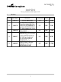
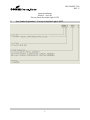
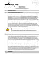
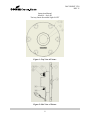
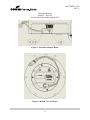
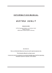
DOCUMENT REVISION September 17, 2009 2529 E Instruction Manual Model 4 – LED Style III Taxiway Omni-directional Light (TOL) L-852T Pro-III In-pavement Omni-directional Fixture Cooper Industries Crouse-Hinds Division Airport Lighting Products 1200 Kennedy Road Windsor, CT 06095 Copyright © 2009 Cooper Technologies Company For Parts or Technical Service Call (860) 683-4300 DOCUMENT 2529 REV. E Instruction Manual Model 4 – Style III Taxiway Omni-directional Light L-852T 1 Revisions Revision Issue/Reissue Letter Number Description Created/Updated Checked Approved A A205-291 INITIAL RELEASE DAT KWF JMM PG KWF 7/3/08 PG KWF 1/20/09 PG KWF 4/7/09 PG KWF 9/17/09 B A208-078 C A208-230 D A209-037 E A209-092 Added item 31 to Figure 5; Parts List, added item 31 & item 8 P/N was 10000-506 & qty was 6 for 12 inch version; 8.5, added support ring to text Parts list item 8 P/N was 10B06-019D32 Parts list item 8 P/N was 10000-518 & qty 12 for 12 inch versions and deleted item 31, P/N 21453, qty 1 and item 7 P/N was 21259; Figure 5, deleted item 31 Parts list item 12 P/N was 21304-2 & item 13 P/N was 21304-2H; 6.1, FAA AC 150/5345-46D was -46C ii DOCUMENT 2529 REV. E Instruction Manual Model 4 – Style III Taxiway Omni-directional Light L-852T 2 Limited Product Warranty THE FOLLOWING WARRANTY IS EXCLUSIVE AND IN LIEU OF ALL OTHER WARRANTIES, WHETHER EXPRESS, IMPLIED OR STATUTORY, INCLUDING, BUT NOT BY WAY OF LIMITATION, ANY WARRANTY OF MERCHANTABILITY OR FITNESS FOR ANY PARTICULAR PURPOSE. Crouse-Hinds Airport Lighting Products (the “Company”) warrants to each original Buyer of Products manufactured by the Company that such Products are, at the time of delivery to the Buyer, free of material and workmanship defects, provided that no warranty is made with respect to: (a) any Product which has been repaired or altered in such a way, in Company’s judgment, as to affect the Product adversely; (b) any Product which has, in Company’s judgment, been subject to negligence, accident or improper storage; (c) any Product which has not been operated and maintained in accordance with normal practice and in conformity with recommendations and published specification of Company; and, (d) any Products, component parts or accessories manufactured by others but supplied by Company (any claims should be submitted directly to the manufacturer thereof). Crouse-Hinds Airport Lighting Products’ obligation under this warranty is limited to use of reasonable efforts to repair or, at its option, replace, during normal business hours, at any authorized service facility of Company, any Products which in its judgment proved not to be as warranted within the applicable warranty period. All costs of transportation of Products claimed not to be as warranted and of repaired or replacement Products to or from such service facility shall be borne by Purchaser. Company may require the return of any Product claimed not to be as warranted to one of its facilities as designed by Company, transportation prepaid by Purchaser, to establish a claim under this warranty. The cost of labor for installing a repaired or replacement product shall be borne by Purchaser. Replacement parts provided under the terms of this warranty are warranted for the remainder of the warranty period of the Products upon which they are installed to the same extent as if such parts were original components thereof. Warranty services provided under the Agreement does not assure uninterrupted operations of Products; Company does not assume any liability for damages caused by any delays involving warranty service. The warranty period for the Products is 24 months from date of shipment or 12 months from date of first use whichever occurs first. iii DOCUMENT 2529 REV. E Instruction Manual Model 4 – Style III Taxiway Omni-directional Light L-852T 3 Safety Notices This equipment is normally used or connected to circuits that may employ voltages that are dangerous and may be fatal if accidentally contacted by operating or maintenance personnel. Extreme caution should be exercised when working with this equipment. While practical safety precautions have been incorporated in this equipment, the following rules must be strictly observed: 3.1 Keep Away from Live Circuits Operating and maintenance personnel must at all times observe all safety regulations. Do not perform maintenance on internal components or re-lamp with power ON. 3.2 Resuscitation Maintenance personnel should familiarize themselves with the technique for resuscitation found in widely published manuals of first aid instructions. IMPORTANT: IMPORTANT See FAA Advisory Circular AC 150/5340-26 for additional information. iv DOCUMENT 2529 REV. E Instruction Manual Model 4 – Style III Taxiway Omni-directional Light L-852T 4 Table of Contents Title Page 1 Revisions 2 Limited Product Warranty 3 Safety Notices 4 Table of Contents 5 Part Number Explanation 6 General Description 6.1 Taxiway Omni-directional Light, L-852T 7 Installation 8 Maintenance 8.1 Cleaning Lenses 8.2 Relamping 8.3 Power Supply Replacement 8.4 O-Ring Replacement 8.5 Lens Replacement 8.6 Feed-thru Replacement 8.7 Pressure Test 8.8 Cleanliness and Workmanship 8.9 Maintenance Program 9 Parts List Figure 1 Top View of Fixture Figure 2 Side View of Fixture Figure 3 Feed-thru Adapter Detail Figure 4 Bottom View of Fixture Figure 5 Sectioned View of Fixture v i ii iii iv v 1 2 2 2 3 3 3 3 4 4 5 5 5 5 7 8 8 9 9 10 DOCUMENT 2529 REV. E Instruction Manual Model 4 – Style III Taxiway Omni-directional Light L-852T 5 Part Number Explanation – Taxiway Centerline Light, L-852T 1 DOCUMENT 2529 REV. E Instruction Manual Model 4 – Style III Taxiway Omni-directional Light L-852T 6 General Description 6.1 Taxiway Omni-directional Light, L-852T The Crouse-Hinds Taxiway Omni-directional Light is a Style 3, FAA L-852T per FAA AC 150/5345-46D. It is designed for installation at the taxiway edge or any other location where visual guidance of moving aircraft or ground vehicles is desirable. The fixture is designed to fit on a FAA L-868, steel, size B or FAA L-867, steel, size B light bases per FAA AC 150/5345-42 (latest version), and have a total height above grade/ground level of .250 inch. The fixture is omni-directional, projecting the beam of light 360° in the horizontal direction. The light fixture consists of a 1-piece aluminum optical assembly. The aluminum optical assembly is mounted to a light base with six bolts (3/8-16 UNC x 7/8 lg., stn. stl.) and lock washers (3/8, stn. stl.). The aluminum housing has a die cast bottom cover that is attached using 4 screws. A o-ring is used to provide a watertight seal between the inner cover and the optical housing. An LED module is secured to the lens bracket, which is fastened to the optical housing. Electrical connections are made at one feed-thru assembly in the inner cover. The feed-thru has an ITS verified L-823 plug for connecting to FAA L-830/ L-831 Isolation Transformer. The outer lens is held into the aluminum housing with a bracket, gaskets and 6 screws. All hardware is type 18-8 stainless steel except for the 6 screws holding the outer lens bracket onto the aluminum housing, which are type 316 cold worked stainless steel. The complete light unit is 11.94 inches in diameter, 5.13 inches deep, and weighs 10.5 lbs. CAUTION: CAUTION 7 Never handle the light assembly by the leads as this can break the waterproof seal. Installation The Style 3 TOL light units are shipped complete and are ready for installation as received. Installation of a light unit is to be done with primary POWER OFF and SECURED. At each light location, install a steel, Size B, 12 inch deep minimum, L-868 Light Base per FAA AC 150/5340-4 (latest revision). For TOL fixtures, the fixture orientation is not a factor; however, it is recommended that all fixtures be installed in the same way, “Crouse-Hinds” label on the aluminum housing towards the center of the taxiway. Place the properly sized isolation transformer in the light base and make necessary primary power connections using L-823 connectors. The TOL light unit requires a minimum 10/15W watt, 6.6A secondary transformer for the standard fixture and a minimum 20/25 watt, 6.6A secondary transformer for the heater option fixture. Verify that the mounting flange on the light base is clean and the o-ring (optional on deep cans) is coated with Dow Corning FS 1292 grease and is in place on the light base. Connect the plug from the light unit to the secondary of the previously installed isolation transformer. Installation tool, Crouse-Hinds P/N 19999, will ease in the installation and removal of the light unit. The threaded eyebolts on the lifting tool screw into threaded holes in the light fixture. Lower the light unit straight down onto the base. The light fixture is subject to optical misalignment or mechanical damage if not seated properly. Secure the light fixture to the base with six 3/8-16 UNC x 7/8 lg., stn. stl. bolts and lock-washers and tighten to 225 -0 +10 in-lbs. (18 ftlbs.). It is recommended that Loctite 242 be used on the mounting bolts to prevent loosening due to vibration. Loctite is required for fixtures subjected to repeated aircraft impacts and roll-overs. 8 Maintenance 2 DOCUMENT 2529 REV. E Instruction Manual Model 4 – Style III Taxiway Omni-directional Light L-852T The preferred method of maintaining these lights is to periodically and systematically replace the units and return it to the maintenance shop for renovation. As an alternative, the units can be serviced in the field. However, it is recommended that field servicing be limited to cleaning the lens only as described in section 8.1. 8.1 Cleaning Lenses With a compressed air blast or suitable brushes, remove all accumulated debris from the unit. Clean the outer lens surface with a detergent solution. If the lens is coated with a substance impervious to the detergent, a suitable solvent should be sparingly applied with a wad of cotton or a patch of cloth on the end of a wood splint. After the solvent has acted the remaining solvent and softened coating should be removed with a clean piece of cotton or cloth. Care should be taken to avoid excessive contact between the solvent and the lens seal. Remove all remaining solvent from lens and seal. A gentle air blast may be used. 8.2 Relamping LED Module Replacement Kit P/N 21334 contains all necessary parts to change the LED module. Remove and secure power to the fixture. Turn the fixture upside down and remove the four screws holding the inner cover to the light housing. Disconnect the LED module leads from the power supply. Remove the lens retaining bracket screws from the light housing. Remove the lens-retaining bracket and remove the LED module and thermal tape by unscrewing the screws. Install the new LED module and thermal tape by reversing the procedure above and making sure that the screws are tightened to 25 - 30 in-lbs; tightening the lens retaining bracket screws may cause damage. For the heater option fixture, make sure that the heater wires are aligned with the slot on the lens retaining bracket so that they are not pinched. Inspect/replace the optical housing’s o-ring per paragraph 8.4. Assemble the inner cover onto the light housing. Assemble the inner cover onto the light housing. The screw-hole patterns in the inner cover and light housing are offset to insure proper alignment. Torque the mounting screws to 25 - 30 in-lbs. Perform a pressure test per paragraph 8.7. Clean the mounting flange area of the base. Place the fixture into the base. Apply Loctite 242 (P/N 10048-30), per manufacturer’s instructions, to all mounting bolts and immediately torque them to 225 - 235 in-lbs. 8.3 Power Supply Replacement Remove and secure power to the fixture. Turn the fixture upside down and remove the four screws holding the inner cover to the light housing. Disconnect the LED module leads from the power supply. Disconnect the power supply leads from the feed-thru on a standard fixture or both the feed-thru and thermostat on a heater option fixture. Remove the power supply bracket screws and remove the bracket, power supply, and rubber isolator. Install a new power supply with the rubber isolator and bracket. Torque the power supply bracket screws to 25 - 30 in-lbs. Inspect/replace the optical housing’s o-ring per paragraph 8.4. Assemble the inner cover onto the light housing. The screw-hole patterns in the inner cover and light housing are offset to insure proper alignment. Torque the mounting screws to 25 - 30 in-lbs. Perform a pressure test per paragraph 8.7. Clean the mounting flange area of the base. Place the fixture into the base. Apply Loctite 242 (P/N 10048-30), per manufacturer’s instructions, to all mounting bolts and immediately torque them to 225 - 235 in-lbs. 8.4 O-Ring Replacement 3 DOCUMENT 2529 REV. E Instruction Manual Model 4 – Style III Taxiway Omni-directional Light L-852T Every time the unit is opened, the o-ring must be closely examined and replaced, if necessary. Any o-ring that is stretched, torn, has permanent set, or some other defect which would prevent it from forming a watertight seal must be replaced with a new o-ring. NOTICE: NOTICE A bad o-ring seal is the most common cause of inset fixture leaks. It is strongly recommended that a new o-ring be installed every time the Optical Assembly is opened Remove the old o-ring from the groove in the optical housing. Carefully clean the o-ring groove and flange mating surface on the inner cover. Take care not to damage the mating surface or the o-ring. Coat the o-ring (P/N 10035-62) with a thin layer of Dow Corning FS 1292 Lubricating grease. Position the new o-ring in the center of the groove and press it into place. Torque the inner cover screws to 25 - 30 in-lbs. Perform a pressure test as described in paragraph 8.6. Clean the mounting flange area of the base. Place the fixture into the base. Apply Loctite 242 (P/N 10048-30), per manufacturer’s instructions, to all mounting bolts and immediately torque them to 225 - 235 in-lbs. NOTICE: NOTICE 8.5 The groove is designed to be wider than the o-ring. This provides room for the displacement of the o-ring when compressed between the housing and mating surface. Properly tightened screws are important in obtaining a complete seal. Lens/Heater Replacement Outer Lens: If an outer lens is broken, leaks, or is badly pitted or scarred, it must be replaced. It is highly recommended that this task be performed in a clean shop environment. Outer Lens Replacement Kit P/N 21332 contains all necessary parts to change a lens. Remove and secure power to the fixture. Turn the fixture upside down and remove the four screws holding the inner cover to the light housing. Remove the lens retaining bracket screws from the light housing. Remove the lens-retaining bracket and support ring and discard the lensretaining gasket. Firmly push the lens/boot assembly from the outside of the light housing; discard the old lens and boot. Thoroughly clean the lens opening with isopropyl alcohol and let dry. Inspect the lens opening for scratches or pits; a damaged lens opening surface will not seal properly. Place a new lens boot (P/N 21256) over the replacement outer lens (P/N 21254). Apply a thin coat of Dow Corning FS 1292 grease over the entire outside surface of the lens boot. Align the lens/boot assembly in the lens opening and press it into place. Verify that the lens boot is not pinched in the lens opening. Using a new lens retaining gasket (P/N 21258), fasten the lens retaining bracket (P/N 21259) and support ring (P/N 21453) to the light housing. Torque the mounting screws to 25 - 30 in-lbs; over tightening these screws may cause damage. Inspect/replace the optical housing’s o-ring per paragraph 8.4. Assemble the inner cover onto the light housing. The screw-hole patterns in the inner cover and light housing are offset to insure proper alignment. Torque the mounting screws to 25 - 30 in-lbs. Perform a pressure test per paragraph 8.7. Clean the mounting flange area of the base. Place the fixture into the base. Apply Loctite 242 (P/N 10048-30), per manufacturer’s instructions, to all mounting bolts and immediately torque them to 225 - 235 in-lbs. 4 DOCUMENT 2529 REV. E Instruction Manual Model 4 – Style III Taxiway Omni-directional Light L-852T Outer Lens with Heater: Outer Lens/Heater Replacement Kit P/N 21333 contains all necessary parts to change a lens/heater assembly. Do as stated above; however, this fixture will not have a lens retaining gasket since it is incorporated into the heater assembly and make sure that when mounting the lens retaining bracket, the heater wires are aligned with the slot on the lens retaining bracket so the wires are not pinched. The heater must be unplugged from the thermostat prior to removing the lens/heater assembly. 8.6 Feed-thru Replacement Remove and secure power to the fixture. Turn the fixture upside down and remove the four screws holding the inner cover to the light housing. Disconnect the power supply leads from the feed-thru terminals. Remove the feed-thru by unscrewing the retaining collar. Clean the mounting surfaces with Isopropyl Alcohol and let dry. Apply a thin coat of Dow Corning FS 1292 grease to the mounting flange of a new feed-thru. Apply a drop of Loctite 242 to the feed-thru adapter threads. Screw the feed-thru retaining collar onto the adapter; refer to Figure 4 for proper inner cover/feed-thru orientation. Torque the retaining collar to 25 - 30 inlbs. Inspect/replace the optical housing’s o-ring per paragraph 8.4. Assemble the inner cover onto the light housing. The screw-hole patterns in the inner cover and light housing are offset to insure proper alignment. Torque the mounting screws to 25 - 30 in-lbs. Perform a pressure test per paragraph 8.7. Clean the mounting flange area of the support ring. Place the Optical Assembly into the base. Apply Loctite 242 (P/N 10048-30), per manufacturer’s instructions, to all mounting bolts and immediately torque them to 225 -235 in-lbs. 8.7 Pressure Test A light fixture should be subjected to a 20-psi air pressure test to verify that it is waterproof whenever it has been opened or components have been replaced. A tire valve style pressure fitting is located on the bottom of the inner cover. Pressurize the fixture to 20-psi then place it in a tub of water or use a soap solution to locate escaping air bubbles. Carefully inspect the areas around the lens, inner cover seal, and feed-thru adapter for leaks. Relieve the internal air pressure before installing the fixture or attempting to repair a leak. WARNING: WARNING 8.8 Do not exceed 20-psi when pressure testing the fixture. Serious injury and/or permanent damage to the fixture may result if a higher air pressure is used. Once the pressure test is complete, be sure to relieve the air pressure. Cleanliness and Workmanship Service life depends upon the entire assembly being waterproof. All surfaces must be clean, dry and free of all foreign matter if the light fixture is to operate for extended periods without requiring maintenance. 8.9 Maintenance Program In order to insure maximum light fixture life, the installed units should be subject to a maintenance program in accordance with the following: 5 DOCUMENT 2529 REV. E Instruction Manual Model 4 – Style III Taxiway Omni-directional Light L-852T A daily operation check should be made of the lighting fixture. The lights should be energized and visually inspected. If any fixtures are out, the location of the fixture should be recorded and the unit inspected at a time when the circuit is de-energized. (See Section 8.2) 8.9.1 Regular cleaning is necessary in order to insure that inset lighting fixtures operate at maximum efficiency. The lens should be cleaned periodically with a soft cloth and solvent. The weather and the location of the fixtures will dictate the regularity and type of cleaning. 8.9.2 Snowplow operators should exercise extra care not to strike the light fixtures with snowplow blades (use rubber blades for added protection to the fixture). After snowplow removal operations, inspect all light fixtures to locate and replace if necessary, any damaged Light Assemblies. Passes over the light rows should be made with a power broom only if practical. Snowplows must NOT traverse TOL fixtures unless they have the blades lifted clear of the fixtures; doing so may cause severe damage to the fixtures. Recommended snow removal techniques are described in AC 150/5200-23. 8.9.3 The light is designed to exclude both ground and surface water from entering. If the lights are not properly maintained (i.e., bolts tightened and seals in good condition) water may enter the fixture. To prevent this from occurring, it is recommended that each fixture be inspected for the presence of water at least once a month. More frequent inspection is desirable during and following rainy seasons. 8.9.4 TOL fixtures hold-down bolts should be checked for proper torque (225 - 235 in-lbs.) at least once every three months or whenever a fixture is serviced regardless of the season. Light fixtures in and around the Touchdown Zone area are especially prone to vibration damage if the mounting bolts are not properly torqued. The mounting surface of the light base must be clean and free of foreign matter when checking mounting bolts. 8.9.5 If any fixture contains water, the water should be removed and the entire fixture cleaned and dried. Perform a pressure test per paragraph 8.7 to locate the source of the leak. Replace the o-ring (100035-62), See Section 8.4. 6 DOCUMENT 2529 REV. E Instruction Manual Model 4 – Style III Taxiway Omni-directional Light L-852T 9 Parts List ITEM NO. STANDARD W/ HEATER STANDARD W/ HEATER STANDARD W/ HEATER 852T4-8 852T4-8-1 852T4-12A 852T4-12A-1 852T4-12B 852T4-12B-1 PART NUMBER DESCRIPTION HOUSING, OPTICAL, 12-INCH 1 0 0 1 1 1 1 21273-XXX 2 1 2 0 0 0 0 21253 HOUSING, OPTICAL, 8-INCH 3 1 1 1 1 1 1 10035-62 O-RING, 3/32 THK, 6.25 I.D., POLYURETHANE, 90 DUROMETER 4 1 1 1 1 1 1 21254 LENS, OUTER 5 1 1 1 1 1 1 21256 BOOT, LENS, OUTER 6 1 1 1 1 1 1 21258 GASKET, LENS RETAINING 7 1 1 1 1 1 1 21259-1 BRACKET, LENS RETAINING 8 6 6 6 6 6 6 10000-519 SCREW, BUTTON HD SOCKET CAP, #10-32 x 3/4 INCH LG, 316 STN STL, CW 9 1 1 1 1 1 1 21312 HEATSINK, LED ASSEMBLY 10 1 1 1 1 1 1 21310 THERMAL TAPE 11 2 2 2 2 2 2 10000-468 SCREW, SEMS, PAN HD TYPE 1A CROSS/DRI-LOC, #10-32x1/2 LG, SSTL 12 1 0 1 0 1 0 21365-1T POWER SUPPLY, LED 13 0 1 0 1 0 1 21365-3T POWER SUPPLY, LED, HEATER OPTION 14 1 1 1 1 1 1 21320 BRACKET, LOCKING, POWER SUPPLY 15 2 2 2 2 2 2 21314 ISOLATOR, POWER SUPPLY 16 2 2 2 2 2 2 10B06-019D12 SCREW, PAN HD, #10-32 X 3/8 LG, STN STL 17 1 1 1 1 1 1 21305 COVER, BOTTOM 18 1 1 1 1 1 1 21120 ADAPTER, THREADED, FEED-THRU, ALUMINUM 19 1 1 1 1 1 1 10035-61 O-RING 20 1 1 1 1 1 1 21122 FEED-THRU ASS'Y, 1 LAMP/1 PLUG, ALUMINUM 21 1 1 1 1 1 1 10000-471 SCREW, PAN HD TYPE 1A CROSS, GREEN, #10-32 x 3/8 LG, 18-8 SS 22 1 1 1 1 1 1 10037-795 FITTING, PRESSURE TEST, 1/8 NPT 23 4 4 4 4 4 4 10000-470 SCREW, 100° FLAT HD/DRI-LOC, #10-32 x 7/16 LG, 18-8 SS 24 0 1 0 1 0 1 21325 HEATER ASSEMBLY 25 0 2 0 2 0 2 10047-2880 CONNECTOR, PIGGY-BACK REC & TAB, 20-16 AWG, BRASS 26 2 3 2 3 3 3 10046-95 WIRE, #16 AWG, STRANDED, 600V, BLACK TEFLON 27 2 2 2 2 2 2 10047-2758 TERMINAL, FLAG, INSULATED, .250 x .032 TAB, 16-14 AWG 28 2 2 2 2 2 2 10047-2868 CONNECTOR, RECEPTACLE INSULATED, #14-16 AWG 29 0 1 0 1 0 1 10047-2943 THERMOSWITCH 30 0 2 0 2 0 2 10033-81 RIVET, POP, 1/8 DIA, .265 LG, #SSD42SSBS 31 7 DOCUMENT 2529 REV. E Instruction Manual Model 4 – Style III Taxiway Omni-directional Light L-852T Figure 1: Top View of Fixture Figure 2: Side View of Fixture 8 DOCUMENT 2529 REV. E Instruction Manual Model 4 – Style III Taxiway Omni-directional Light L-852T Figure 3: Feed-thru Adapter Detail Figure 4: Bottom View of Fixture 9 DOCUMENT 2529 REV. E Instruction Manual Model 4 – Style III Taxiway Omni-directional Light L-852T Figure 5: Sectioned View of Fixture 10