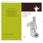
1
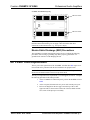
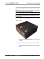
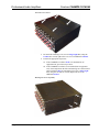
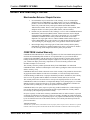
Crestron CNAMPX-12/16X60
Professional Audio Amplifiers
Service Guide
This document was prepared and written by the Technical Documentation department at:
Crestron Electronics, Inc.
15 Volvo Drive
Rockleigh, NJ 07647
1-888-CRESTRON
All brand names, product names and trademarks are the property of their respective owners.
©2006 Crestron Electronics, Inc.
Crestron CNAMPX-12/16X60
Professional Audio Amplifiers
Contents
Professional Audio Amplifiers: CNAMPX-12/16X60
1
Service Guide Overview.......................................................................................1
General Safety Precautions ....................................................................1
Rack Mounting Precautions ...................................................................2
Electro-Static Discharge (ESD) Precautions ..........................................3
AC Power Fuse Replacement ...............................................................................3
Internal Replacement Procedures .........................................................................5
Disconnect Unit and Cover Removal.....................................................5
Amplifier Module Replacement.............................................................8
Audio Output Relay Board Replacement .............................................12
Cresnet System Interface Card Replacement .......................................12
In-Rush Surge Suppressor Replacement ..............................................15
Cover Installation and Reconnect Unit ................................................16
Problem Solving .................................................................................................20
Further Inquiries...................................................................................20
Future Updates .....................................................................................20
Return and Warranty Policies.............................................................................21
Merchandise Returns / Repair Service .................................................21
CRESTRON Limited Warranty ...........................................................21
Service Guide - DOC. 5885B
Contents • i
Crestron CNAMPX-12/16X60
Professional Audio Amplifiers
Professional Audio Amplifiers:
CNAMPX-12/16X60
Service Guide Overview
This guide provides service instructions for the CNAMPX-12X60 and CNAMPX16X60 Professional Audio Amplifiers. The amplifiers contain two-channel amplifier
modules (six in the CNAMPX-12X60 and eight in the CNAMPX-16X60), a
Crestron® remote control system (herein referred to as the Cresnet® system) interface
card, and an AC power fuse that are field replaceable. For any other components that
need replacement, the unit must be returned to the factory for repair service. Refer to
“Merchandise Returns/Repair Service” on page 21 and contact Crestron customer
service for further information.
The CNAMPX-12X60 and CNAMPX-16X60 amplifiers are also available as
international versions. All of the features are identical with the exceptions of
international AC power requirements, power cords and unit nomenclatures of
CNAMPXI-12X60 and CNAMPXI-16X60, respectively. Throughout this service
guide, all references apply to all models and all versions except where noted.
General Safety Precautions
Read all precautions, information, and instructions provided in this service
guide.
Retain this service guide.
Heed all warnings and cautions printed in this service guide.
Follow all instructions in the order that they are provided.
Do not use this unit near water.
Clean unit only with a damp cloth.
Do not block any of the ventilation openings. Install or re-install in accordance
with the instructions in this service guide.
Do not install unit near any heat sources such as radiators, heat registers, stoves,
or other apparatus that produce heat. If installing or re-installing multiple
amplifiers, follow the instructions provided in this service guide.
Service Guide – DOC.5885B
Professional Audio Amplifiers: CNAMPX-12/16X60 • 1
Professional Audio Amplifiers
Crestron CNAMPX-12/16X60
Do not defeat the safety purpose of the polarized or ground-type plug. A
polarized plug has two blades with one wider that the other. A grounding type
plug has two blades and a third grounding prong. The wide blade or the third
prong is provided for safety. When the provided plug does not fit into an outlet,
consult an electrician for replacement of the obsolete outlet.
Protect the power cord from being walked on or pinched particularly at plugs,
convenience receptacles (if provided), and the point where they exit the unit.
Unplug this unit during lighting storms or when unused for long periods of time.
Rack Mounting Precautions
WARNING: To prevent bodily injury when mounting or servicing this unit in a
rack, you must take special precautions to ensure that the system remains stable. The
following precautions are provided to ensure your safety.
If the rack is provided with stabilizing devices, install the stabilizers before
mounting or servicing the unit in the rack.
When an equipment rack is used, use caution when moving the rack/unit
combination to avoid injury or tip-over.
WARNING: The CNAMPX-12/16X60 amplifiers are heavy units. The CNAMPX12X60 weighs approximately 81.40 lbs (37.00 kg) and the CNAMPX-16X60 weighs
approximately 90.20 lbs (41.00 kg). Use more than one person to remove unit from
or install unit into rack.
When mounting this unit in a partially filled rack, load the rack from the bottom
to the top with the heaviest component at the bottom of the rack.
The unit should be mounted at the bottom of the rack if it is the only unit in the
rack.
CAUTION: Due to the heat dissipation of the CNAMPX-12/16X60 (and all audio
amplifiers in general), allow at least one free rack space above and below the
CNAMPX-12/16X60 for proper circulation. Refer to the diagram on the next page.
2 • Professional Audio Amplifiers: CNAMPX-12/16X60
Service Guide - DOC. 5885B
Crestron CNAMPX-12/16X60
Professional Audio Amplifiers
CNAMPX-12/16X60 Rack Spacing
ONE RACK SPACE
POWER
PROFESSIONAL
AUDIO
12 CHANNEL
CRESTRON
AMPLIFIER
60 WATTS
CNAMPX-12/16X60
ONE RACK SPACE
NOTE: Reliable grounding of rack mounted equipment should be maintained.
Particular attention should be given to supply connections other than direct
connections to the branch circuit. (e.g., use of power strips).
Electro-Static Discharge (ESD) Precautions
The CNAMPX-12/16X60 contains ESD sensitive devices. Perform the following
procedures while wearing a grounding strap that is properly grounded or on a
grounded work station to avoid damaging the unit.
AC Power Fuse Replacement
The AC power fuse replacement of the CNAMPX-12/16X60 does not require cover
removal and can be performed with the unit installed in an equipment rack.
NOTE: The unit shown in this procedure is a CNAMPX-16X60. The procedure is
identical for all models and all versions except where noted.
The only tool required for fuse replacement is a #1 flat-tipped screwdriver. Complete
the following procedure in the order provided.
Service Guide - DOC. 5885B
1.
At the CNAMPX-12/16X60 front panel, position the POWER switch to
OFF.
2.
At the rear panel, disconnect the AC power cord from the power port.
3.
Refer to the diagram on the next page. Insert the tip of the #1 flattipped screwdriver between the retainer tab of the fuse holder and the
fuse section of the input power assembly.
Professional Audio Amplifiers: CNAMPX-12/16X60 • 3
Professional Audio Amplifiers
Crestron CNAMPX-12/16X60
Fuse Holder Retainer Tab
4.
Carefully push the fuse holder retainer tab upwards until the tab
releases and remove the fuse holder.
CAUTION: Refer to the table below. Use only the listed fuse for each
corresponding CNAMPX model and version to replace a defective fuse. The fuse is
available commercially but if a replacement fuse cannot be obtained, contact
Crestron customer service.
CNAMPX MODEL
CNAMPX-12X60 1
CURRENT
RATING
VOLTAGE
RATING
1-1/4 in
12A
125V (or 250V)
FUSE SIZE
DIAM. x LENGTH
1/4 in
x
2
5mm
x
20mm
6.3A
250V
CNAMPX-16X60 1
1/4 in
x
1-1/4 in
15A
125V (or 250V)
CNAMPXI-16X60 2
5mm
x
20mm
8A
250V
CNAMPXI-12X60
The characteristics of all listed fuses are FAST-ACTING.
1
2
The fuse holder of non-international versions contains a spare fuse. Verify that the spare
fuse is the same type, size and rating as the defective fuse and use as the replacement. If
the spare fuse is used as the replacement, obtain the same type, size and rating fuse to be
used as the spare as soon as possible.
The fuse holder of international versions contains two active fuses. Verify the defective
fuse(s) and replace as necessary.
5.
Remove the defective fuse(s) according to the appropriate step below.
5a. For NON-international versions, remove the defective fuse from
the right compartment of the fuse holder and insert the
replacement fuse.
5b. For international versions, verify the defective fuse(s) and replace
as necessary.
6.
With the retainer tab facing downward, insert fuse holder into the fuse
section of the input power assembly until it snaps into place.
7.
At the rear panel, re-connect the AC power cord to the power port.
8.
At the front panel, position the POWER switch to ON.
4 • Professional Audio Amplifiers: CNAMPX-12/16X60
Service Guide - DOC. 5885B
Crestron CNAMPX-12/16X60
Professional Audio Amplifiers
Internal Replacement Procedures
Internal replacement procedures consist of Amplifier Module, Audio Output Relay
Board Replacement (not contained in CNAMPX-12X60), Cresnet System Interface
Card procedures, and In-Rush Surge Suppressor. Prior to performing any of these
procedures, the Disconnect Unit and Cover Removal procedure must be performed.
After the internal procedure(s) has been performed, the Cover Installation and
Reconnect Unit procedure is performed.
Disconnect Unit and Cover Removal
To replace the internal components of the CNAMPX-12/16X60, the unit must first
be disconnected and the cover removed. To disconnect the unit, the only tool
required is a #2 Phillips screwdriver and the only tool required to remove the cover is
the 1/8-inch hex wrench supplied with the unit. Complete the following procedure in
the order provided.
WARNING: The CNAMPX-12/16X60 amplifiers are heavy units. The CNAMPX12X60 weighs approximately 81.40 lbs (37.00 kg) and the CNAMPX-16X60 weighs
approximately 90.20 lbs (41.00 kg). Use more than one person to remove unit from
or install unit into rack.
CAUTION: To prevent stripping of screw heads, threads, or mounting holes, do
NOT overtighten screws. Tighten only to the specification listed in the individual
step(s).
NOTE: The unit shown in this procedure is a CNAMPX-16X60. The procedure is
identical for all models and all versions except where noted.
Service Guide - DOC. 5885B
1.
At the CNAMPX-12/16X60 front panel, position the POWER switch to
OFF.
2.
At the rear panel, disconnect the AC power cord from the power port.
3.
Detach the Cresnet system wiring connector from the NET port.
4.
Using a #2 Phillips screwdriver, loosen the ground screw, remove the
ground wire, and retighten the screw.
5.
Label and detach all audio input and output cables/wires from the
respective connectors.
6.
Use at least two people to place the CNAMPX-12/16X60 on a suitable
work surface.
Professional Audio Amplifiers: CNAMPX-12/16X60 • 5
Professional Audio Amplifiers
7.
Crestron CNAMPX-12/16X60
Depending upon the particular installation, rack mounting ears may or
may not be installed. Perform the appropriate step below.
7a. If rack mounting ears are NOT installed, continue to step 8 below.
7b. If rack mounting ears are installed, refer to the diagram below.
Using the 1/8-inch hex wrench, remove the mounting ear screws
and ears from the left and right sides of the CNAMPX-12/16X60.
Mounting Ear Screws (Left-Side)
8.
Refer to the diagram below. Using the 1/8-inch hex wrench, remove
the three screws from the top-front edge, then remove the four screws
from the left side and four screws from the right side.
Top-Front and Side Cover Screws
6 • Professional Audio Amplifiers: CNAMPX-12/16X60
Service Guide - DOC. 5885B
Crestron CNAMPX-12/16X60
9.
Professional Audio Amplifiers
Refer to the diagram below. Using the 1/8-inch hex wrench, remove
the four screws from the top-center of the cover.
NOTE: The four screws at the top-center of the cover are 1/2-inch long. The
remaining cover screws are 1/4-inch. When reinstalling the cover, these screws are
NOT interchangeable.
Top-Center Cover Screws
10. Refer to the diagram below. Using the 1/8-inch hex wrench, remove
the three screws from the top-rear of the cover.
Top-Rear Cover Screws
11. Remove the cover and proceed to the appropriate internal replacement
procedure.
Service Guide - DOC. 5885B
Professional Audio Amplifiers: CNAMPX-12/16X60 • 7
Professional Audio Amplifiers
Crestron CNAMPX-12/16X60
Amplifier Module Replacement
The tools required for amplifier module replacement in the CNAMPX-12/16X60 are
a grounding strap (or grounded workstation), a #1 Phillips screwdriver, and 5/64inch and 5/32-inch hex wrenches.
To replace an amplifier module, the defective module must be returned to Crestron
and a replacement must be obtained from Crestron. Refer to “Merchandise
Returns/Repair Service” on page 21 and contact Crestron customer service for
further information.
WARNING: The CNAMPX-12/16X60 amplifiers are heavy units. The CNAMPX12X60 weighs approximately 81.40 lbs (37.00 kg) and the CNAMPX-16X60 weighs
approximately 90.20 lbs (41.00 kg). Use more than one person to remove unit from
or install unit into rack.
CAUTION: The CNAMPX-12/16X60 amplifier modules contain ESD sensitive
devices. Perform the following procedures while wearing a grounding strap that is
properly grounded or on a grounded work station to avoid damaging the module
and/or unit.
CAUTION: To prevent stripping of screw heads, threads, or mounting holes, do
NOT overtighten screws. Tighten only to the specification listed in the individual
step(s).
NOTE: The unit shown in this procedure is a CNAMPX-16X60. The procedure is
identical for all models and all versions except where noted.
NOTE: The CNAMPX-12/16X60 modules operate independently. If a replacement
module is not available, the unit may be operated without all modules.
NOTE: To replace a defective module of the CNAMPX-16X60, starting from
module #8, all modules prior to the defective module MUST be removed. As an
example, to replace module #5, modules #8, #7, and then #6 must be removed first.
This procedure contains optional steps to accommodate removal of the appropriate
module(s) and should be followed carefully.
NOTE: For the CNAMPX-12X60, any defective module other than module #6 may
be removed directly. Replacement of module #6 requires partial removal of the
Cresnet system interface card. This procedure contains optional steps to
accommodate removal of the card and should be followed carefully.
1.
Make sure that the “Disconnect Unit and Cover Removal” procedure
on page 5 has been performed.
2.
Facing the left-side (the side with the rear panel Cresnet system NET
connectors) of the CNAMPX-12/16X60, stand the unit onto its rightside.
3.
Refer to the diagram on the next page. Using a 5/32-inch hex wrench,
remove the appropriate (refer to the note above) module bottom screws
(two screws per module).
8 • Professional Audio Amplifiers: CNAMPX-12/16X60
Service Guide - DOC. 5885B
Crestron CNAMPX-12/16X60
Professional Audio Amplifiers
Module Bottom Screws
NOTE: For the CNAMPX-16X60, there is minimum clearance between the
modules. When removing the module brace screws, do not allow the screws to fall
between the modules. If screws fall between the modules, additional modules may
have to be removed.
4.
Position the unit bottom-side down onto the work surface. Refer to the
diagram below (view is from overhead). Using a 5/32-inch hex wrench,
remove the module brace screws (12 for the CNAMPX-12X60, 16 for
the CNAMPX-16X60) and remove both braces.
Module Brace Screws
Service Guide - DOC. 5885B
Professional Audio Amplifiers: CNAMPX-12/16X60 • 9
Professional Audio Amplifiers
5.
Crestron CNAMPX-12/16X60
Access to modules of the CNAMPX-12X60 is slightly different than
access to CNAMPX-16X60 modules. Perform the appropriate step
below.
5a. To replace module #6 of the CNAMPX-12X60 or any module of
the CNAMPX-16X60, continue to step 6 below.
5b. To replace a module other than module #6 of the CNAMPX12X60, proceed to step 8 on page 11.
6.
Refer to the diagram below. Using a #1 Phillips screwdriver, remove
the screw that secures the card to the vertical bracket.
Cresnet System Interface Card Vertical Bracket Screw
7.
Refer to the diagram below. Holding the card by hand and using a 5/64inch hex wrench, remove the two mounting screws that secure the card
and allow the card to hang by its wiring.
Cresnet System Interface Card Mounting Screws
10 • Professional Audio Amplifiers: CNAMPX-12/16X60
Service Guide - DOC. 5885B
Crestron CNAMPX-12/16X60
8.
Professional Audio Amplifiers
Removal of the CNAMPX-12X60 modules is slightly different than
removal of CNAMPX-16X60 modules. Perform the appropriate step
below.
8a. For the CNAMPX-12X60, refer to the diagram below. By hand,
detach the four connectors from the defective module and remove
the module.
8b. For the CNAMPX-16X60, refer to the diagram below. By hand,
detach the four connectors from module #8 (module #8 is nearest
the interface board) and remove this module. Repeat this step until
access to the specific module to be replaced is obtained and
remove the module. For example, to replace module #5, modules
#8, #7, and then #6 must first be removed.
Module Connectors
NOTE: The CNAMPX-12/16X60 modules operate independently. If a replacement
module is not available, the unit may be operated without all modules.
NOTE: The CNAMPX-12/16X60 may be operated without all modules. The
suspected bad module may be verified by swapping with a known good module.
NOTE: To obtain a replacement module, refer to “Merchandise Returns/Repair
Service” on page 21 and contact Crestron customer service for further information.
9.
Module replacement of the CNAMPX-12X60 and the CNAMPX16X60 are slightly different. Perform the appropriate step below.
9a. In the CNAMPX-12X60, orient and position the replacement
module into the CNAMPX-12X60 and re-attach the four
connectors to the module.
9b. In the CNAMPX-16X60, orient and position the replacement
module into the CNAMPX-16X60 and re-attach the four
connectors to the module. If other modules have been removed to
gain access to the defective module, orient and position the next
module into the unit and re-attach the four connectors to the
module. Repeat for each subsequent module.
Service Guide - DOC. 5885B
Professional Audio Amplifiers: CNAMPX-12/16X60 • 11
Professional Audio Amplifiers
Crestron CNAMPX-12/16X60
10. Module replacement of the CNAMPX-12X60 and the CNAMPX16X60 are slightly different. Perform the appropriate step below.
10a. To replace module #6 of the CNAMPX-12X60 or any module of
the CNAMPX-16X60, continue to step 11 below.
10b. To replace a module other than module #6 of the CNAMPX12X60, proceed to step 14 below.
11. Make sure that the card is outward of the vertical bracket and position
the card to its mounting holes.
12. Re-install the two card mounting screws to finger-tight then, using a
5/64-inch hex wrench, tighten the screws an additional 1/8-turn.
13. Re-install the card vertical bracket screw to finger-tight then, using a
#1 Phillips screwdriver, tighten the screw an additional 1/8-turn.
14. Re-install all module brace screws and appropriate module bottom
screws to finger-tight then, using 5/32-inch hex driver wrench, tighten
the screws an additional 1/4-turn.
15. Perform the appropriate step below.
15a. If performing another internal replacement procedure, proceed to
that procedure.
15b. If NOT performing another internal replacement procedure,
perform the “Cover Installation and Reconnect Unit” procedure on
page 16
Audio Output Relay Board Replacement
NOTE: The CNAMPX-12X60 does not contain an audio output relay board. This
procedure applies only to the CNAMPX-16X60.
The audio output relay board of the CNAMPX-16X60 requires extensive
disassembly of the unit and is NOT recommended by Crestron. If the audio output
relay board is suspected of being bad, the CNAMPX-16X60 must be returned to
Crestron. Refer to “Merchandise Returns/Repair Service” on page 21 and contact
Crestron customer service for further information.
Cresnet System Interface Card Replacement
The only tools required to replace the Cresnet system interface card in the
CNAMPX-12/16X60 are a grounding strap (or grounded workstation), a #1 Phillips
screwdriver, and a 5/64-inch hex wrench.
To replace the card, the defective card must be returned to Crestron and a
replacement must be obtained from Crestron. Refer to “Merchandise Returns/Repair
Service” on page 21 and contact Crestron customer service for further information.
12 • Professional Audio Amplifiers: CNAMPX-12/16X60
Service Guide - DOC. 5885B
Crestron CNAMPX-12/16X60
Professional Audio Amplifiers
WARNING: The CNAMPX-12/16X60 amplifiers are heavy units. The CNAMPX12X60 weighs approximately 81.40 lbs (37.00 kg) and the CNAMPX-16X60 weighs
approximately 90.20 lbs (41.00 kg). Use more than one person to remove unit from
or install unit into rack.
CAUTION: The CNAMPX-12/16X60 Cresnet system interface card contains ESD
sensitive devices. Perform the following procedures while wearing a grounding strap
that is properly grounded or on a grounded work station to avoid damaging the card
and/or unit.
CAUTION: To prevent stripping of screw heads, threads, or mounting holes, do
NOT overtighten screws. Tighten only to the specification listed in the individual
step(s).
NOTE: The CNAMPX-12/16X60 Cresnet system interface card provides Cresnet
system control and is used to activate AC power. DO NOT attempt to operate the
CNAMPX-12/16X60 with the card removed.
NOTE: The unit shown in this procedure is a CNAMPX-16X60. The procedure is
identical for all models and all versions except where noted.
1.
Make sure that the “Disconnect Unit and Cover Removal” procedure
on page 5 has been performed.
CAUTION: The two connectors at the bottom-right of the Cresnet system interface
card are both 2-pin connectors that are electrically NOT interchangeable. Observe
the wire colors and/or label the connectors.
2.
Refer to the diagram below. Facing the left-side (the side with the rear
panel Cresnet system connectors) of the CNAMPX-12/16X60, hold the
card by hand and disconnect all connectors (one for the CNAMPX12X60, six for the CNAMPX-16X60) from the card.
Cresnet System Interface Card Connectors
CAUTION: In the diagram above, the connector “A” has one black and one blue
wire; the connector “B” has two black wires. Make certain these connectors are not
reversed when reconnected.
Service Guide - DOC. 5885B
Professional Audio Amplifiers: CNAMPX-12/16X60 • 13
Professional Audio Amplifiers
3.
Crestron CNAMPX-12/16X60
Refer to the diagram below. Using a #1 Phillips screwdriver, remove
the screw that secures the card to the vertical bracket.
Cresnet System Interface Card Vertical Bracket Screw
4.
Refer to the diagram below. Holding the card by hand and using a 5/64inch hex wrench, remove the two screws that secure the card to the rear
panel and remove the card.
Cresnet System Interface Card Mounting Screws
NOTE: To obtain a replacement Cresnet system interface card, refer to
“Merchandise Returns/Repair Service” on page 21 and contact Crestron customer
service for further information.
5.
Make sure that the replacement card is outward of the vertical bracket
and position the card to its mounting holes.
6.
Re-install the two card mounting screws to finger-tight then, using a
5/64-inch hex wrench, tighten the screws an additional 1/8-turn.
7.
Re-install the card vertical bracket screw to finger-tight then, using a
#1 Phillips screwdriver, tighten the screw an additional 1/8-turn.
CAUTION: The two connectors at the bottom-right of the Cresnet system interface
card are both 2-pin connectors that are electrically NOT interchangeable. Observe
the wire colors and/or connector labels. Refer to the CAUTION at the bottom of the
previous page.
14 • Professional Audio Amplifiers: CNAMPX-12/16X60
Service Guide - DOC. 5885B
Crestron CNAMPX-12/16X60
Professional Audio Amplifiers
8. Re-connect all connectors (one for the CNAMPX-12X60, six for the
CNAMPX-16X60) to the card.
9.
Perform the appropriate step below.
9a. If performing another internal replacement procedure, proceed to
that procedure.
9b. If NOT performing another internal replacement procedure,
perform the “Cover Installation and Reconnect Unit” procedure on
page 16.
In-Rush Surge Suppressor Replacement
Follow the instructions below to replace the in-rush surge suppressor in the
CNAMPX-12/16X60.
Tools/material required
Grounding strap or grounded workstation
#2 Phillips screwdriver
Needle-nose pliers
1/8-inch hex wrench (supplied with the unit)
5/64-inch hex wrench (not supplied)
Thread sealer (Three Bond 1401C or equivalent)
WARNING: To prevent bodily injury or equipment damage, position the
CNAMPX-12/16X60 POWER switch to OFF, disconnect the power cord, and detach
Cresnet from the NET port.
1.
Perform the “Disconnect Unit and Cover Removal” procedure provided
on page 5.
2.
Once the top cover is removed, locate the terminal block assembly in
the left front corner near the power switch.
3.
Using needle-nose pliers, carefully remove the “push-on” type
connectors one at a time, and connect them to the corresponding
connection on the replacement in-rush surge suppressor assembly, part
number 2008782, one at a time to avoid incorrect wiring.
NOTE: The two brown and black wires that are screwed into place DO-NOT need
to be removed, as they are included in the new assembly.
Service Guide - DOC. 5885B
4.
Remove the large black and white wires on the top of the main relay (to
the left of the terminal block) one at a time, and replace them with the
like wires from the new assembly.
5.
Tilt the chassis on its side and, using the 5/64-inch hex wrench, remove
the two 6-32 screws that mount the old assembly to the chassis.
6.
Remove the old assembly.
7.
Remove the 6-32 hex nuts from the old assembly and re-install onto the
replacement in-rush surge suppressor assembly. Install the assembly
into the chassis, making sure the insulator sheet remains in place, reusing the two screws from step 5 (refer to photo).
Professional Audio Amplifiers: CNAMPX-12/16X60 • 15
Professional Audio Amplifiers
Crestron CNAMPX-12/16X60
Installation of In-Rush Surge Suppressor
8.
Tighten the two screws snug – do not over-tighten. Apply Three Bond
1401C (or similar thread sealer) to the nuts to prevent loosening.
9.
Verify that the thermistor is not in contact with any components to
allow for ambient air movement around it.
CAUTION: The thermistor becomes hot during normal operation. Therefore,
component damage may occur if components are touching the hot thermistor.
10. Perform the appropriate step below.
10a. If performing another internal replacement procedure, proceed to
that procedure.
10b. If NOT performing another internal replacement procedure,
perform the “Cover Installation and Reconnect Unit” procedure
below.
Cover Installation and Reconnect Unit
After replacement of internal components of the CNAMPX-12/16X60, the cover
must be installed and the unit reconnected. The only tool required for cover
installation is the 1/8-inch hex wrench supplied with the unit. The only tool required
to reconnect the unit is a #2 Phillips screwdriver. Complete the following procedure
in the order provided.
WARNING: The CNAMPX-12/16X60 amplifiers are heavy units. The CNAMPX12X60 weighs approximately 81.40 lbs (37.00 kg) and the CNAMPX-16X60 weighs
approximately 90.20 lbs (41.00 kg). Use more than one person to remove unit from
or install unit into rack.
16 • Professional Audio Amplifiers: CNAMPX-12/16X60
Service Guide - DOC. 5885B
Crestron CNAMPX-12/16X60
Professional Audio Amplifiers
CAUTION: To prevent stripping of screw heads, threads, or mounting holes, do
NOT overtighten screws. Tighten only to the specification listed in the individual
step(s).
NOTE: The unit shown in this procedure is a CNAMPX-16X60. The procedure is
identical for all models and all versions except where noted.
1.
Orient and position the cover onto the CNAMPX-12/16X60.
CAUTION: The cover screws are 1/4-inch except the four screws at the top-center
that are 1/2-inch long. To prevent stripping of screws and/or screw holes, do NOT
interchange the screws.
2.
Allow cover to overhang front panel and install top-rear cover screws
(shown on the next page) to finger-tight.
Top-Rear Cover Screws
3.
By hand, push cover towards rear panel until the top-front cover screw
holes align.
CAUTION: The four screws at the top-center of the cover are 1/2-inch long. The
remaining cover screws are 1/4-inch. To prevent stripping of screws and/or screw
holes, do NOT interchange the screws.
4.
Service Guide - DOC. 5885B
As shown on the next page, install top-center cover screws to fingertight.
Professional Audio Amplifiers: CNAMPX-12/16X60 • 17
Professional Audio Amplifiers
Crestron CNAMPX-12/16X60
Top-Center Cover Screws
5.
Re-install all remaining cover screws to finger-tight then, using the
1/8-inch hex wrench, tighten all cover screws an additional 1/8-turn.
6.
Perform the appropriate step below.
6a. If the CNAMPX-12/16X60 is NOT to be installed into an
equipment rack, proceed to step 9 below.
6b. If the CNAMPX-12/16X60 is to be installed into an equipment
rack, orient and position the left-side mounting ear as shown below
and re-install the three rack mounting ear screws to finger-tight
then, using the 1/8-inch hex wrench, tighten the screws an
additional 1/8-turn.
Mounting Ear Screws (Left-Side)
18 • Professional Audio Amplifiers: CNAMPX-12/16X60
Service Guide - DOC. 5885B
Crestron CNAMPX-12/16X60
7.
Professional Audio Amplifiers
Orient and position the right-side mounting ear and re-install the three
rack mounting ear screws to finger-tight then, using the 1/8-inch hex
wrench, tighten the screws an additional 1/8-turn.
WARNING: Observe the “Rack Mounting Precautions” on page 2 to install unit
into equipment rack.
WARNING: The CNAMPX-12/16X60 amplifiers are heavy units. The CNAMPX12X60 weighs approximately 81.40 lbs (37.00 kg) and the CNAMPX-16X60 weighs
approximately 90.20 lbs (41.00 kg). Use more than one person to install unit into
rack.
8.
Using at least two people, install unit into rack.
9.
At the rear of the CNAMPX-12/16X60, attach the labeled audio input
and output cables/wires to their respective connectors.
10. Using a #2 Phillips screwdriver, loosen the ground screw, attach the
ground wire, and retighten the screw.
11. Attach the Cresnet system wiring connector to the NET port.
12. Connect the AC power cord to the power port.
13. At the front panel, position the POWER switch to ON.
Service Guide - DOC. 5885B
Professional Audio Amplifiers: CNAMPX-12/16X60 • 19
Professional Audio Amplifiers
Crestron CNAMPX-12/16X60
Problem Solving
Further Inquiries
If you cannot locate specific information or have questions after reviewing this
guide, please take advantage of Crestron's award winning customer service team by
calling the Crestron corporate headquarters at 1-888-CRESTRON [1-888-273-7876].
For assistance in your local time zone, refer to the Crestron website
(http://www.crestron.com/) for a listing of Crestron worldwide offices.
You can also log onto the online help section of the Crestron website to ask
questions about Crestron products. First-time users will need to establish a user
account to fully benefit from all available features.
Future Updates
As Crestron improves functions, adds new features, and extends the capabilities of
the CNAMPX-12/16X60, additional information may be made available as manual
updates. These updates are solely electronic and serve as intermediary supplements
prior to the release of a complete technical documentation revision.
Check the Crestron website periodically for manual update availability and its
relevance. Updates are identified as an “Addendum” in the Download column.
20 • Professional Audio Amplifiers: CNAMPX-12/16X60
Service Guide - DOC. 5885B
Crestron CNAMPX-12/16X60
Professional Audio Amplifiers
Return and Warranty Policies
Merchandise Returns / Repair Service
1.
No merchandise may be returned for credit, exchange, or service without prior
authorization from CRESTRON. To obtain warranty service for CRESTRON
products, contact an authorized CRESTRON dealer. Only authorized CRESTRON
dealers may contact the factory and request an RMA (Return Merchandise
Authorization) number. Enclose a note specifying the nature of the problem, name
and phone number of contact person, RMA number, and return address.
2.
Products may be returned for credit, exchange, or service with a CRESTRON Return
Merchandise Authorization (RMA) number. Authorized returns must be shipped
freight prepaid to CRESTRON, 6 Volvo Drive, Rockleigh, N.J., or its authorized
subsidiaries, with RMA number clearly marked on the outside of all cartons.
Shipments arriving freight collect or without an RMA number shall be subject to
refusal. CRESTRON reserves the right in its sole and absolute discretion to charge a
15% restocking fee, plus shipping costs, on any products returned with an RMA.
3.
Return freight charges following repair of items under warranty shall be paid by
CRESTRON, shipping by standard ground carrier. In the event repairs are found to
be non-warranty, return freight costs shall be paid by the purchaser
CRESTRON Limited Warranty
CRESTRON ELECTRONICS, Inc. warrants its products to be free from manufacturing defects in
materials and workmanship under normal use for a period of three (3) years from the date of
purchase from CRESTRON, with the following exceptions: disk drives and any other moving or
rotating mechanical parts, pan/tilt heads and power supplies are covered for a period of one (1)
year; touchscreen display and overlay components are covered for 90 days; batteries and
incandescent lamps are not covered.
This warranty extends to products purchased directly from CRESTRON or an authorized
CRESTRON dealer. Purchasers should inquire of the dealer regarding the nature and extent of the
dealer's warranty, if any.
CRESTRON shall not be liable to honor the terms of this warranty if the product has been used in
any application other than that for which it was intended, or if it has been subjected to misuse,
accidental damage, modification, or improper installation procedures. Furthermore, this warranty
does not cover any product that has had the serial number altered, defaced, or removed.
This warranty shall be the sole and exclusive remedy to the original purchaser. In no event shall
CRESTRON be liable for incidental or consequential damages of any kind (property or economic
damages inclusive) arising from the sale or use of this equipment. CRESTRON is not liable for
any claim made by a third party or made by the purchaser for a third party.
CRESTRON shall, at its option, repair or replace any product found defective, without charge for
parts or labor. Repaired or replaced equipment and parts supplied under this warranty shall be
covered only by the unexpired portion of the warranty.
Except as expressly set forth in this warranty, CRESTRON makes no other warranties, expressed
or implied, nor authorizes any other party to offer any warranty, including any implied warranties
of merchantability or fitness for a particular purpose. Any implied warranties that may be imposed
by law are limited to the terms of this limited warranty. This warranty statement supercedes all
previous warranties.
Trademark Information
All brand names, product names, and trademarks are the sole property of their respective owners. Windows is a registered
trademark of Microsoft Corporation. WindowsMe/XP and WindowsNT/2000 are trademarks of Microsoft Corporation.
Service Guide - DOC. 5885B
Professional Audio Amplifiers: CNAMPX-12/16X60 • 21
Crestron Electronics, Inc.
15 Volvo Drive Rockleigh, NJ 07647
Tel: 888.CRESTRON
Fax: 201.767.7576
www.crestron.com
Service Guide – DOC. 5885B
06.06
Specifications subject to
change without notice.