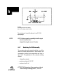
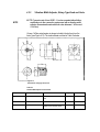
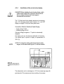
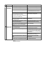
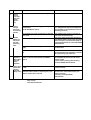
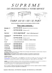
1
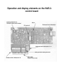
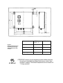
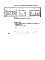
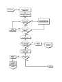
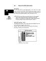
Operating Manual VIBTRONIC-Connector Sets for Magnetic Vibrators Series SA...-2 in panel mounting and cabinet unit Operation and display elements on the VAE-2control board Intended Use VIBTRONIC connector sets of type SA...-2 and SAE...-2 are designed and constructed as alternating voltage regulators for controlling magnetic vibrators; they operate on the voltage regulation principle (phase regulation). The connector set has been designed for use with mains networks having a frequency of either 50 or 60 Hz and a sinusoidal voltage. Do not use the connector set in environments where there is a danger of explosions and/or pit gas! Observe the information regarding the intended uses given in chapter 1.3! For your safety You will find three different types of symbols in this operating manual which are intended to point out important information: DANGER ATTENTION! NOTE . . DANGER! The DANGER warning describes procedures or conditions which could have dangerous or even life-threatening consequences for the person installing or using the equipment WARNING! You will find this information with procedures in which a danger of damage to equipment exists. These damages could also result in injury to personnel (e.g. resulting from a fire!) NOTE: Notes provide information regarding individual tasks. Notes explain circumstances, clarify terminology or provide tips for simplifying processes or procedures Although we developed the VIBTRONIC connector sets taking into account all safety measures, operational error cannot be completely eliminated. In the interest of your safety and that of your colleagues, observe the following information: DANGER DANGER DANGER! Life threatening voltages are present within the connector set when it is connected to the mains voltage. Contact with voltage-carrying components can be fatal! Before switching on mains, ensure that contact with voltagecarrying components is not possible! DANGER! Explosions can be life threatening and result in great damage to equipment. When using the connector sets in environments where the danger of explosion exists, take appropriate precautions! WARNING! Unsuitable connector sets, operation with the incorrect mains voltage/frequency will result in damage to the magnetic vibrator. Make sure that the connection values are correct and compare them with the deviceATTENTION! type plates! © 1996 AVITEQ Vibrationstechnik GmbH COPYRIGHT The VIBTRONIC connector sets, Series SA...-2 and SAE...-2 as well as this operation manual are copyright protected. Any reproduction of the units will be prosecuted. All rights of this operating manual are reserved, including reproduction via photo mechanical, print, data or any other possible medium, as well as in translation. Reproduction of this operating manual, complete or in part, may only be carried out with the written consent of AVITEQ Vibrationstechnik GmbH. VIBTRONIC is a registered and protected trademark of AVITEQ Vibrationstechnik GmbH. This operating manual contains the most exact description of the product possible. However, it does not guarantee particular features or application results. Prior to publication, this operating manual has been subjected to thorough verification. The authors guarantee that this manual is free of faults which cancel or reduce its utility or suitability for the intended use of the device. However, the publisher does not undertake any liability, either explicitly or implicitly, for damages or consequential damages resulting from the application of the operating manual. We are always grateful for criticism or hints regarding imperfections, and suggestions for possible improvements! Unless otherwise stated, the relevant state of engineering is that at the time of the combined delivery of the product and the operating manual from AVITEQ Vibrationstechnik GmbH. The product is subject to technical changes without prior notice. Previous operating manuals are no longer valid. The AVITEQ General Conditions of Sale, adopted by AVITEQ Vibrationstechnik GmbH, are valid. Do you have questions? Or problems with installation and commissioning? Give us a call! We'll be glad to help you! AVITEQ Vibrationstechnik GmbH Im Gotthelf 16 65795 Hattersheim Tel. 06145-503 0 Fax 06145-503 200 Hattersheim, Germany 31. December 2000 Chapter Contents General notices regarding this operating manual, our Conditions of Sale, the Warranty and the Intended Use of the connector sets Shipping, storage, delivery contents and disposal Here you learn the fundamentals of the connector set and its selections: The function description Assembly, electrical connection To the point: Commissioning Step by Step Prevention is better: Service and Maintenance Not to be forgotten: Troubleshooting Seek and find: the Index TABLE OF CONTENTS 1 1.1 1.2 1.3 1.4 1.5 2 2.1 2.2 2.3 2.3.1 2.3.2 2.3.3 3 3.1 3.2 3.3 3.4 3.4.1 3.4.2 3.4.3 4 4.1 4.1.1 4.1.2 4.2 4.2.1 4.2.2 4.2.3 4.2.4 4.2.5 4.2.6 4.2.7 4.3 4.3.1 4.3.2 We are Partners. 1-1 About this Operating Manual.............................................................................................................. Product Liability and Warranty............................................................................................................ Fields of Application.......................................................................................................................... Maintenance and Repair..................................................................................................................... Installation and Operating Personnel................................................................................................. 1-2 1-4 1-6 1-7 1-8 Transport, Delivery, Disposal 2-1 Transport and Storage .........................................................................................................................2-2 Extent of Delivery................................................................................................................................ 2-2 Disposal................................................................................................................................................ 2-3 Packing Materials................................................................................................................................. 2-3 Returning the Device............................................................................................................................ 2-3 Unit Component Materials................................................................................................................... 2-4 Function Description 3-1 Introduction.......................................................................................................................................... Operating Principle.............................................................................................................................. Scope of Operation............................................................................................................................... Series and Models................................................................................................................................ Series.................................................................................................................................................... Models...........................................................................................................................................-...... Type Designations................................................................................................................................ 3-2 3-2 3-3 3-5 3-5 3-5 3-6 Installation 4-1 Mechanical Installation........................................................................................................................ 4-2 Panel Mounting Unit............................................................................................................................ 4-2 Cabinet Unit...................................................................................................................................... 4-3 Binding Post Assignment..................................................................................................................... 4-5 Connecting the magnetic vibrator........................................................................................................ 4-5 Vibration sensor (PAL) and temperature switch ................................................................................ 4-6 Vibration sensor (PAL)......................................................................................................................... 4-7 Primary and Fine Fill Rates.................................................................................................................. 4-8 External control input........................................................................................................................... 4-9 Operational message and actual-value display ..................................................................................4-11 Switching On/Off Externally............................................................................................................ 4-12 Electrical Connection......................................................................................................................... 4-14 Notes on electrical connection........................................................................................................... 4-14 Connection Diagram.......................................................................................................................... 4-15 4.3.3 4.3.4 4.4 4.4.1 4.4.2 5 5.1 5.1.1 5.1.2 5.2 5.2.1 5.2.2 5.3 6 4-17 4-18 4-20 4-20 4-21 Commissioning 5-1 Commissioning with AVITEQ magnetic vibrator............................................................................................ Commissioning Procedure .................................................................................................................. ............. Special Notes...................................................................................................................................................... Commissioning with Vibrators from Other Manufacturers ............................................................................ Setting the Vibrator Mains Voltage .................................................................................................................. Commissioning .................................................................................................................................................. Note on the DIP switch block .............................................................................................................. ............ 5-2 5-2 5-2 5-3 5-3 5-3 5-8 Maintenance 6-1 6.1 Maintenance........................................................................................................................................................ 6-2 Troubleshooting 7-1 7.1 7.2 Fault causes and remedies........................................................................................................................ Help by Telephone .................................................................................................................................... 7-2 7-5 INDEX i 7 8 Vibration-Width Adjuster, Rotary-Type Knob and Scale .................................................................. Installation of the actual-value display .............................................................................................. Electrical Connection to the Magnetic Vibrator................................................................................. Electromagnetic Compatibility (EMC).............................................................................................. Line Lengths....................................................................................................................................... 1 We are Partners. 1.1 About this Operating Manual 1.2 Product Liability and Warranty 1.3 Fields of Application and Intended Use 1.4 Maintenance and Repair 1.5 Installation and Operating Personnel Chapter Outline Although you might want to get immediately started with our connector set, we would like you to read this chapter first. It provides a summary of the contents of the operating manual and settles our legal relationship as parties to a contract. 1.1 About this Operating Manual For whom? This operating manual is directed to the • installation technician who installs and commissions the magnetic vibrator. • electrician or engineer who carries out the installation of the connector set, the electrical connection to the mains network and the connection to the magnetic vibrator. All work concerning the connector set must be carried out by qualified personnel only (a certified electrician or an electrically trained person according to IEC 364 and EN 60204-1). DANGER DANGER! Electrically live components! Risk of lethal shock when mains is connected. Observe the aforementioned safety notices and precautions when installing and commissioning! Additional Publications Supplements to this operating manual: • Connection diagram and dimension sheet for the connector set Definitions Magnetic vibrator, electromagnetic-mechanical unit for operating a vibration conveyor device • Vibration conveyor device: unit consisting of the magnetic vibrator and working unit (through, tube, screen, etc.) • Connector set: the separately delivered electronic control unit assigned to the magnetic vibrator for connecting to the mains network • Cabinet unit: connector set in compact housing for wall or frame mounting (type SA...-2) • Panel mounting unit: connector set without housing for installation in the switching cabinet or in enclosed control locations (type SAE...-2) • NOTE NOTE: This operating manual applies to panel mounting and cabinet units. Any differences are indicated. Special Indicators in This Operating Manual You have already learned how safety notices are indicated, or...? If there are still unclear points regarding safety when working with and around the connector sets, give us a call! We do not want you to endanger yourself or others just because the possible dangers were not clear to you! For your convenience and orientation, we use the following special indicators in this operating manual: • A round dot stands for listings of characteristics and conditions A checked box tells you to check for something or to read a summary. The pointing finger marks operation steps that you have to carry out. Date of Revision On each right-hand page of the operating manual you will find the date when this page has last been updated. A Small Request Help us in improving our connector sets and operating manuals by giving us your opinion. Please take a moment to fill out the questionnaire at the end of this manual. Share your criticisms and comments with us! We will reward your effort by (even) better products and manuals in the future. 1.2 Product Liability and Warranty The connector sets have been designed for a long service life. They correspond to the current state of science engineering and have been tested individually for each of its guaranteed functions prior to delivery. AVITEQ Vlbrationstechnik GmbH continually conducts product and market analyses for further development and improvement. Should malfunctions or failures occur despite these preventative measures, please contact our service department! We guarantee that appropriate measures for the repair of the defect will be taken immediately. Conditions of Warranty We guarantee the functioning of the product as described in this operating manual for a period of 12 months after the date of delivery as stated on the delivery invoice. The condition for free repair is adherence to the operating manual when storing, shipping, installing, commissioning and operating the product. We guarantee that the product is free of faults as defined by our advertisements, product information published by us, and this operating manual. Beyond that, no product properties are guaranteed. We do not accept responsibility for the efficiency or faultless functioning, or for uses other than those described on the first interior right-hand page of this manual. Warranty Exclusions Manipulation of the device by the customer or a third party is permissible only after prior separate consultation and written consent on the part of AVITEQ Vlbrationstechnik GmbH. In the case of neglect, we assume no responsibility for resulting damages to property, personal injury, or consequential damages; in this case, the warranty becomes void. Claims for damages are generally excluded, except in cases of intent, gross negligence on the part of AVITEQ Vibrationstechnik GmbH, or failure to meet guaranteed product properties. In particular, we do not accept liability for cases where the connector sets are used for purposes for which they are not suited, as defined by this operating manual. If the devices are used in surroundings or with main circuits and control systems that are not suited for the connector sets, that are faulty, or that do not comply with the current state of engineering, we are not liable for the consequences. Moreover, we decline any liability for damages to conveyor and automation systems caused by malfunctions of the product or faults in the operating manual. We are not liable for consequences caused by accessories that were not delivered or certified by AVITEQ Vibrationstechnik GmbH. We are not responsible for the violation of patent rights and other titles of third parties outside of the Federal Republic of Germany. We are not libable for damages due to inappropriate handling as defined in this operating manual. We explicitly exclude liability for profit loss, and particularly for consequential damages caused by non-compliance with safety notices and warnings. The VIBTRONIC connector set models described in this operating manual must not be operated in the United States of America and other countries where US American laws are applicable. The General Terms of Delivery for Products and Services of the electrical industry (issue: May 1993) and the General Conditions of Sale (issue: March 1994) of AEG, which have been adopted by AVITEQ Vibrationstechnik GmbH are valid. 1.3 Fields of Application VIBTRONIC connector sets, types SA...-2 and SAE...-2, hereafter abbreviated with SA(E)...-2, allow infinite adjustment of the working stroke on the magnetic vibrator and thereby of the conveyor rate from vibration conveyor devices. The connector sets must be used together only with AVITEQ magnetic vibrators or corresponding magnetic vibrators from other manufacturers in accordance with their intended use. Information in the vibration conveyor device operating manual is also to be observed! The connector sets must only be operated with magnetic vibrators from other manufacturers when their connection specifications are identical to those of the AVITEQ magnetic vibrators. For more information, see Chapter 5.2! There are no other intended uses for the connector sets. Never attempt the following: • Do not use in environments with explosion hazards (explosives, pit gas environments, hazard of dust explosion)! The units are not protected against explosions! • Do not use at ambient temperatures below -25 and over +40 °C (cabinet unit) and + 50 °C (panel mounting unit), or in tropical climates or areas where dew or condensation could form! The units are designed for operation in moderate climatic environments (DIN IEC 721)! • Do not use together with magnetic vibrators which are not compatible with the connector sets! Do not use mains networks and mains frequencies other than those for which the connector sets were designed! • • Do not use at altitudes exceeding 1,000 m above sea level! The connector set is not designed for high altitudes. Contact us if you have questions! Connecting to Mains and Magnetic Drives Only AVITEQ connector sets connected to a sinusoidal mains network may be used for operating the AVITEQ Magnetic Drives. For each AVITEQ Magnetic Drive model there is a corresponding connector set. Other control and connection options are not included. ATTENTION! ATTENTION! If a magnetic vibrator is directly connected to mains or an inappropriate connector set is used, the magnetic vibrator may be destroyed. Use only the appropriate connector set! 1.4 Maintenance and Repair The connector set contains no components which can be serviced or repaired by the installer or the operator. Do not open the units under any circumstances. In case of failure, send it to AVITEQ Vibrationstechnik GmbH, Hattersheim, Germany. Refer to Chapters 6 and 7 if the connector set does not function as intended! DANGER DANGER! When the unit is connected to mains, dangerously high voltages are present inside the connector set and the magnetic drive. Touching electrically live components can be lethal! Before switching on mains power, ensure that no live parts can be touched! 1.5 Installation and Operating Personnel Prior to installation and/or commissioning, you should familiarise yourself with all details of the connector set and with the connection options of the magnetic vibrator. For more information, see the chapter in the operating manual on connecting the magnetic vibrators. Persons involved with installation, commissioning, assembly, disassembly, adjustment or maintenance must have read and understood this operating manual completely; particularly the safety notices. If you have any questions, we would be glad to help you! All work on the connector set must be carried out by qualified personnel only (a certified electrician or an electrically trained person according to IEC 364 and EN 60204-1). The connector sets must be serviced only by qualified personnel trained and authorised by AVITEQ Vibrationstechnik GmbH, Hattersheim, Germany. In case of negligence, AVITEQ Vibrationstechnik GmbH, Hattersheim, Germany assumes no responsibility for personal injury or damage to property. 2 Transport, Delivery, Disposal 2.1 Transport and Storage 2.2 Extent of Delivery 2.3 Disposal Chapter Outline For storage and transport, certain measures must be observed in order to prevent damamge to the units. The extent of delivery must be checked after unpacking. The packing material should be disposed of properly. What to do with the VIBTRONIC connector sets when they are no longer required? The "return guarantee". 2.1 Transport and Storage • Delivery: the connector sets and accessories are delivered in appropriate packing so that they reach their destination without damage. NOTE NOTE: If the packing is visibly damaged in a way that indicates damage to the contents, contact the forwarding agent! In farther proceedings, take notice of the General Conditions of Business of the forwarding agent in order not to risk your claim for damages! Storage: unless special agreements concerning packing and storage have been made, the units, either packed or unpacked, must be stored and transported under "normal" conditions. This means in enclosed rooms with temperatures between -25 and +65 °C, relative humidity not to exceed 80 % (no dew or condensation), and no mechanical shocks or vibrations. ATTENTION! ATTENTION! Storing and transporting the units under inappropriate conditions may cause permanent damage. Such damage may not be detectable from the outside. AVITEQ Vibrationstecbnik GmbH declines any responsibility in this case and is not liable for the consequences. 2.2 Extent of Delivery After unpacking, check that all parts are complete and undamaged, and that they are consistent with the delivery invoice and accompanying documents. The extent of delivery includes the connector set (either the cabinet or panel mounting unit) and the connection diagram - packed together with the connector set. Also included with installation units is the separate rotary potentiometer for setting the working stroke with rotary-type knob and scale. Compare the data on the magnetic vibrator and connector set type-plates with the delivery invoice and order documents! Check to see that the magnetic vibrator and connector set match by referring to Chapter 3-4.2 of this operating manual! Before using magnetic vibrators from other manufacturers, you must first make certain that the specifications are suitable for operation with the V1BTRONIC connector set (see Chapter 5.2)! If in doubt, contact us! We'll be glad to help you! ATTENTION! ATTENTION! Unauthorised combinations may result in destruction of the magnetic vibrator or connector set! Mains voltage, mains frequency and vibration frequency must be compatible! The nominal current of the connector set must be the same or greater than the peak current of the magnetic vibrator. Connect only compatible devices! 2.2 Disposal 2.3.1 Packing Materials The following materials are used by us for delivering connector sets, depending on the type of transport. • Polyethylene foil (PE) for device protection • Corrugated cardboard for outer and inner packing • Wooden cases for outer packing • Paper shavings for filler material • Styrofoam (Flo-Pack) for filler and damping material. All packing materials should be disposed of in accordance with local regulations of the delivery destination. Cardboard containers and paper packing tapes can be recycled within the RESY Disposal and Re-utilisation System. Packing foils, tapes and foam foils (if used) consist of polyethylene (PE), the CFC/HCFC-free padding normally of foamed polystyrene (PS). These packing materials consist of pure hydrocarbons and can thus be recycled. In special cases, we use steel packing bands and wooden cases free of chemical treatment. 2.3.2 Returning the Device AVITEQ Vibrationstechnik GmbH takes back connector set types SA(E)...-2, delivered after 1995, free of charge if delivered to AVITEQ Vibrationstechnik GmbH, Hattersheim, Germany. 2.3.3 Unit Component Materials In the case of disposal by the customer, and when exchanging components, local effective waste and disposal regulations should be observed. We accept no responsibility for improperly disposed of parts and components! • Regulations regarding the disposal of electronic parts and components apply to the disposal of the connector set. • The power semiconductor (thyristor and diode module) do not contain beryllium and thus can be disposed of as electronic waste. NOTE NOTE: Detailed information concerning the used materials is available from us upon request. In case of doubt, take advantage of our disposal offer! 3 Function Description 3.1 Introduction 3.2 Operating Principle 3.3 Scope of Operation 3.4 Series and Models 3.5 Type Designation Chapter Outline After a description of the operating principle of the connector sets, a discussion of the scope of operation and of the connection options follows in chapter 3.3. The final sections provide you with an overview of the available connection set models and the type designations. 3.1 Introduction AVITEQ magnetic vibrators must be operated with the appropriate VIBTRONIC connector sets. Depending on the application and size of the magnetic drive, AVITEQ Vlbrationstechnik GmbH supplies connector sets from the SA(E)...-2 in size F, G or H, available in cabinet and panel mounting units. 3.2 Operating Principle Oscillation rates and mains frequency Connector sets of type SA(E)...-2 are alternating-voltage regulators and function on the voltage regulation principle (phase regulation). • • • Connector sets for vibration conveyor devices with an oscillation rate of 1,500 min"1 (25 Hz) at a mains frequency of 50 Hz and 1,800 min"1 (30 Hz) at a mains frequency of 60 Hz fire every fourth mains half-wave. Connector Sets for vibration conveyor devices with an oscillation rate of 2,000 min'1 (33 1/3 Hz) with a mains frequency of 50 Hz fire every third mains half-wave. Connector sets for vibration conveyor devices with an oscillation rate of 3,000 min"1 (50 Hz) at a mains frequency of 50 Hz and 3,600 min"1 (60 Hz) at a mains frequency of 60 Hz fire every second mains halfwave. The mechanical vibration frequency (25,30,33 1/3, 50 or 60 Hz) is set at the factory prior to delivery and is encoded in the type designation. NOTE NOTE: This new generation of connector sets was designed with the EMV directive (89/336/EWG) in mind and meets the requirements of EN 50081-2 and W50082-2. NOTE NOTE: Oscillation rates are given in "min'1" and the vibration frequency in"Hz". 3.3 Scope of Operation The VIBTRONIC Connector Sets of type SA(E)...-2 are designed for the following regulation types: • Voltage regulation • Working stroke regulation • Voltage regulation with limit protection • Effective working stroke regulation The various regulation types are described below. Voltage-, working stroke- and effective working stroke regulation Connector Sets of the type SA(E)...-2 can be operated with voltage regulation or working stroke regulation with limit monitoring. Temperature monitoring of the magnetic vibrator is also possible. NOTE NOTE: In normal operation the Connector Sets junction (without vibration sensor PAL on the AVITEQ magnetic vibrators) as voltage regulators. If however, AVITEQ-magnetic vibrators with PAL are used (type designation: MV..-...P), limit protection in the upper control range is automatically regulated by means of the working stroke. Connector Sets of type SA(E)...-2S1 are set in the factory for effective working stroke regulation by means of an external vibration sensor (type: PA...). Temperature monitoring is possible. NOTE NOTE: The Connector Sets function as a voltage regulator when binding posts 13 and 14 are bridged. In this case, a magnetic vibrator must not be operated with a vibration sensor (PAL)! Presetting the Command Value The command value for the working stroke can optionally be preset by means of a vibration-width adjuster (potentiometer) or • an external control input (0...10 V, 4...20 mA or 0...20 mA) • 3.4 Series and Models 3.4.1 Series Three series of VIBTRONIC connector sets with various characteristics are available: • • • NOTE Type series SU(E)... without voltage regulation in cabinet and panel mounting units for nominal currents up to 6 A. Type series SC(E)... with voltage regulation in cabinet and panel mounting units for nominal currents up to 14 A. Type series SA(E)... with voltage and working stroke regulation in cabinet and panel mounting units for nominal currents up to 43 A. NOTE: In this operating manual, only the connector sets of series SA(E)...-2 are covered. 3.4.2 Models The connector sets are available in the sizes F, G and H in the following variants: Cabinet unit SA... (JP54): enclosed compact housing for securing to walls or frames. Vibration-width adjuster and mains switch are installed on the front side of the housing. • • Panel mounting unit SAE... (IP 00): controller block for installing in the switching cabinet or in closed control locations • The corresponding technical data are located in Table 3-a: • Table 3-a Technical data for Connector Sets SA(E)...-2 SA(E)-FS..-2 Mains frequency SA(E)-GS..-2 SA(E)-HS..-2 50 or 60 Hz Vibration frequency with 50 Hz mains 25, 33 1/3 or 50 Hz Vibration frequency with 60 Hz mains 30 or 60 Hz Nominal voltage(s) with 50 Hz mains 220...240 V 380... 420V 460...500V 380...420V 460...500V Nominal voltage(s) with 60 Hz mains 220...240V 440... 480V 440...480V Table 3-a (Continued) Technical data for Connector Sets SA(E)...-2 SA(E)-FS..-2 SA(E)-GS..-2 SA(E)-HS..-2 Nominal current 25A 23 A 43 A Maximum power loss in switching cabinet 75 W 70 W 85 W NOTE NOTE: The permissible tolerances are, for the mains voltage, ± 10.0 % and, for the mains frequency, ± 0.5 %. NOTE NOTE: The vibration frequency is set at the factory prior to delivery and must not by changed by the customer. 3.4.3 Type Designations Explanation of the type designation for the VIBTRONIC connector sets type SA(E)...-2: NOTE NOTE: As shown in Table 3-a (Technical Data), the connector sets are designed for various voltage ranges. Please see the type plate for the voltage range of the connector set. 4 Installation 4.1 Mechanical Installation 4.2 Binding Post Assignment 4.3 Electrical Connection 4.4 Electrical Connection to the Magnetic Drive Chapter Outline This chapter describes the mechanical and electrical installation of the connector sets up to and including the connection to the magnetic vibrator. 4.1 Mechanical Installation The installation steps for the two versions are described in the following sections: • Panel mounting unit, in Chapter 4.1.1 and • Cabinet unit, in Chapter 4.1.2 4.1.1 Panel Mounting Unit The connector sets are available as installation units for vertical installation in switching cabinets or control cases. They consist of: • • • • DANGER the heat sink with power semiconductor, the power component with main current connection, the control board (type VAE-2) and the potentiometer with rotary-type knob and scale (delivered loose). DANGER! Prior to installation: before opening the switching cabinet or control case, switch off the current supply, check that no voltages are present, and protect against unintentional reconnection! Use the hole pattern to orient yourself, see Figure 4.1 on the following page. Fasten the unit to a vibration-free vertical support wall or installation plate in the closeable switching cabinet (control location); hand-tighten the screws and use only the intended holes. Install the supplied potentiometer for working stroke adjustment with scale, rotary-type knob, pointer, and knob cover at a suitable location (e.g. switching cabinet door or front of control case). ATTENTION! ATTENTION! Connector sets are temperature sensitive! Make certain that the units are not installed near external beat sources, such as direct sunshine or radiators. The ambient temperature must not exceed +50 °C during operation! 4.1.2 Cabinet Unit The connector sets are available in an enclosed cabinet(IP 54 in accordance with EN 60529). The cabinet unit is suitable for mounting to vertical walls or frames. Figure 4.1 Panel mounting unit dimensions and hole pattern for securing to vertical vibration-free switching cabinet walls or installation plates Weight: 3 kg Carry out the installation as follows: Screw the mounting plates (delivered loose) onto the cabinet as shown in Figure 4.2. Use the hole pattern in Figure 4.2 to orient yourself, and drill the necessary holes for the fastening screws. Hand-fasten the mounting plates to a vibration-free vertical wall or frame. ATTENTION! ATTENTION! Connector sets are vibration sensitive! Do not install on vibrating components, and under no circumstances to the vibration conveyor device itself! Figure 4.2 Cabinet unit Dimensions and hole pattern for securing to vertical vibration-free walls or frames ATTENTION! Dimensions in mm SA-FS...-2 SA-GS...-2 SA-HS...-2 Depth T 155 210 Height H 300 380 h 244 324 Weight (kg) 12 15 ATTENTION! Connector sets are temperature sensitive! Make certain that the units are not installed near external heat sources, such as direct sunshine or radiators. The ambient temperature must not exceed +40 °C during operation! 4.2 Binding Post Assignment The following sections 4.2.1 to 4.2.6 explain the binding post assignment on the connector sets as well as the available options. Read these sections before you begin wiring, and observe the information regarding electromagnetic compatibility! NOTE NOTE: The symbol for the control board for each connection diagram is located in the left margin. An arrow mark in each installation step helps you locate the binding posts and display or adjustment elements. 4.2.1 Connecting the magnetic vibrator The minimum binding post assignment of a magnetic vibrator • for voltage-regulated operation and • without external control input shows Figure 4.3. Binding posts 13 and 14 must be connected by a bridge. Figure 4.3 Standard binding post assignment with mains input (binding posts PE. 1 and 2). Magnetic Vibrator (binding posts 3 and 4) and vibration-width adjuster (binding posts 5.6 and 7) NOTE NOTE NOTE: For Magnetic Vibrators without a vibration sensor and/or temperature switch, binding posts 13 and 14 must be connected by a wire bridge. If the bridge is missing, the red LED (HOT/ERROR x) lights up and the operational message relay opens. As a result, the vibrator voltage at binding posts 3 and 4 goes to zero; the Magnetic Vibrator ceases to function. NOTE: Use only potentiometers (limit values between 1 and 10 kOhm) with linear characteristics for the vibration-width adjuster Shield the signal lines to guarantee electromagnetic compatibility if the lines exceed five metres in length! 4.2.2 Vibration sensor (PAL) and temperature switch AVITEQ Magnetic Vibrators, series • MV_S... (with temperature switch) and • MV_S...P (with temperature switch and vibration sensor) are fitted at the factory with a flexible, 5-conductor connection cable. Remove the wire bridge from binding posts 13 and 14. Connect the two black wires of the connection cable for the temperature switch and/or vibration sensor to binding posts 13 and 14 (see Figure 4.4). Figure 4.4 Vibration sensor and temperature switch (binding posts 13 and 14) ATTENTION! ATTENTION! Destruction of the vibration sensor/temperature switch by connecting to the false bindingposts! Never connect the two black wires to binding posts 3 and 4! NOTE NOTE: For line lengths longer than 50 m between magnetic vibrator and connector set: use a separate cable for the two black vibration sensor/temperature switch signal lines. NOTE NOTE: Electromagnetic compatibility: if the line lengths are longer than 100 m, the two black signal lines must be shielded. 4.2.3 Vibration sensor (PA) An external vibration sensor can be connected to Connector Set, type SA(E)...-2S1 (see Figure 4.5). Figure 4.5 External vibration sensor (binding posts 13 and 14) NOTE NOTE: The installation of vibration sensor, type PA..., is described in the separate appendix to this Operating Manual. NOTE NOTE: Electromagnetic compatibility: if line lengths exceed five metres, the signal lines must be shielded. 4.2.4 Primary and Fine Fill Rates When using the connector set for dosing and filling processes, we recommend a circuit as shown in Figure 4.6. In this circuit the two relays K1/K2 function as follows: • K2 initiates the filling process. • Kl switches at 95% full weight. • At 100% full weight, both relays return to their rest positions. Figure 4.6 Primary- and precision-currant switching (binding posts 5,6 and 7) NOTE NOTE: To prevent switching faults, use only gold-plated or hermetically sealed contacts. NOTE NOTE: Use only potentiometers (limit values between 1 and 10 kObm) with linear characteristics for the vibration-width adjuster. Shield the signal lines to guarantee electromagnetic compatibility if the lines exceed five metres in length! 4.2.5 External control input The connector sets may be operated with an external command value entry (extraneous control input). The following extraneous command values can be used for setting the working stroke: • 0...10 V DC, resistance approx. 40 kOhm • 4...20 mA DC, working resistance 100 Ohm • 0...20 mA DC, working resistance 100 Ohm NOTE NOTE: If necessary, you can switch between external control inputs by means of a switch or relay or between command value presetting? by means of a vibration-width adjuster (potentiometer). NOTE NOTE: To prevent switching faults, use only gold-plated or hermetically sealed contacts. Figure 4.7 shows the various options and binding post assignments for presetting extraneous command values. ATTENTION! NOTE ATTENTION! Connection set damage! The illustrated extraneous command values and their respective binding post assignments are not compatible with one another! NOTE: Use onty potentiometers (limit values between 1 and 10 kObm) with linear characteristics for the vibration-width adjuster Shield the signal lines to guarantee the electromagnetic compatibility if the lines exceed five metres in length! 4.2.6 Operational message and actual-value display Operational message relay The Connector Set is fitted with an operational message relay with change-over contact: • Make contact (31 and 30): Vibrator in operation • Break contact (31 and 32): Vibrator standstill, w=0 or START=off or foult (HOT/ERRORx or w>x), the particular condition can be read from the corresponding LEDs. Figure 4.8 Operational message relays NOTE ATTENTION! NOTE: The maximum load capacity of the operational message relay is, for direct current, 60 W, and, for alternating current, 50VA.The maximial voltages are, respectively, 30 V DC and 250 VAC. ATTENTION! Destruction of the operational message relay and possibly of the connector set! When dimensioning, note the permissible values given above for the load of the operational message relay. Actual-value display It is possible to connect a digital actual-value display for the working stroke. This additional device can be ordered under order number 58210132 from AVITEQ Vibra-tionstechnik, Frankfurt, Germany. The binding post assignments for the connection are shown in Figure 4.9. The mechanical installation of the actual-value display is described in Chapter 4.3.4. Figure 4.9 Connecting the actual-value display Note: at 10 V, display shows 100.0 (%) The decimal point is set at the factory for a 100.0 (%) display range. NOTE NOTE: Electromagnetic compatibility: shield the signal lines for the actual-value display if line lengths exceed 5 metres. 4.2.7 Switching On/Off Externally The connector set can be externally switched on or off by means of a switch (relajl buttons or optical coupler. The corresponding binding post assignments are shmj in Figure 4.10. Requirements for the external switching element: • voltage-free contacts • precision contacts for 10 V DC • maximum load 5 mA ATTENTION! Destruction of the connector set: do not connect voltage to binding posts 21, 22 or 23! ATTENTION! Figure 4.10 Switching On/Off externally NOTE NOTE: To prevent switching faults, use only gold-plated or hermetically sealed contacts. NOTE: With external on/off switches, i.e. when binding posts 21,22 and 23, an assigned, the first switch on the DIP switch block is to be set to OFF (left) (For details on the DIP switch block settings, see Chapter 5.3). NOTE DANGER! NOTE: Shield the signal lines to guarantee electromagnetic compatibility if the lines exceed five metres in length! 4.3 Electrical Connection 4.3.1 Notes on electrical connection DANGER! Avoid accidents, observe regulations! When earthing, resetting, or cm rying out protective switching, WE regulations (Germany) and directives specifed by the responsible energy supplier are applicable! The connection must be carried out only by trained personnel (certified electrician or elet trically trained person in accordance with IEC364 and EN 60204-1). Switch off the current supply. Check that no voltages are present! Protect against unintentional reconnection! Mains Fuse Protection For mains fuse Fll (see Figure 4.11), we recommend a fuse appropriate for th nominal current of the connected magnetic vibrator. ATTENTION! ATTENTION! ImproperJuses could result in damage to the magnetic vibrator! Note the dimensioning of the mains fuses at the installation site. 4.3.2 Connection Diagram For the connector set connection diagram, see Figure 4.11. Hie appropriate connection diagram is delivered with each connector set. Note the minimum binding post assignment (Figure 4.3 in Chapter 4.2.1). Rgure4.11 Panel mounting unit connection diagram 4.3.3 NOTE Vibration-Width Adjuster, Rotary-Type Knob and Scale NOTE: Connector sets of type SA(E)...-2 can be operated without further modifications to the connection assignment with a vibration-width adjuster (linearpotentiometer with limit value between 1 kOhm and 10 kObm). A linear 1 kOhm potentiometer is always included in the delivery from the factor] (see Figure 4.12). The technical data are listed in Table 4-a below. Figure 4.12 Potentiometer, rotary-type knob, scale Table 4-a Vibration-Width Adjuster Technical Data Component Type Data Weight Order No. Potentiometer Megatron MUP 4000 I kOhm linear Rotation angle: 300° 35 g 582IO I33 Rotary-type knob 334.6/63/ 1 00 Plastic, black 26 g 580680I3 Scale SE2-02I Polished aluminium; dial graduation and numbers, black 20 g 58 920 20 1 4.3.4 DANGER Installation of the actual-value display DANGER! Before installing the actual-value display, switch off the current supply to the Connector Set and check that no voltages are present! Protect against unintentional reconnection! The 3 1/2 digit actual-value display operates at a measuring rate of 2.5 measure-ments/s and consists of a red LED display unit (height 14 mm) in a black plastic case. Connection Data for theActual Value Display • Supply voltage 5 VDC • Measuring range 20 VDC If the input voltage is negative, a "-"-symbol is automatically displayed. The display units are checked and calibrated at the factory. The decimal point is preset to display a representation of 100.0 (%). NOTE NOTE: To change the setting of the decimal point, solderbridges, in accordance with Figure 4.3, must be installed. Figure 4.13 Marking the solder bridges for changing the decimal point setting The scaling factor can be varied approx. ± 20 % from measuring range with potentiometer PI for measurement-value matching, if necessary. Dimensions and measurement inputs are to be taken from Figure 4.14. Figure 4.14 Actual-value display (dimensions and connection assignments) Installation Steps Switch off the current supply from the installation area and check that no voltages are present! Fit front cutout (30.5 x 57 mm) Install display and secure with strap Solder connections from rear Switch on display and, if necessary, fine-tune with potentiometer PI NOTE NOTE: The rear side of the actual-value display has IP 00 type protection, the front side has IP 50 type protection. Note tijis when retrofitting in a switching cabinet or housing. 4.4 Electrical Connection to the Magnetic Vibrator A connection diagram is included with each VIBTRONIC connector set. The connection diagram is also included in this operating manual in Chapter 4.3.2 (see Figure 4.11). Make all the connections between mains, connector set, command value circuit, and magnetic vibrator. When working with the available options, note the device-typical peculiarities and the applicable binding post assignments chapters 4.2.1 to 4.2.6 shown earlier in this chapter. DANGER DANGER! When the unit is connected to mains, life-threatening voltages are present inside Ihe connector set. Touching electrically live components can be lethal! Before switching on mains power, ensure that no live parts can be touched. Close the cover of the control case or switch cabinet door(s)! 4.4.1 Electromagnetic Compatibility (EMC) The connector sets of series SA(E)...-2 were developed and constructed in confor-mance with EMC directive 89/336/EWG. They fulfil the requirements of standards EN 50081-2 and EN 50082-2. ATTENTION! NOTE ATTENTION! The connector sets are designed in accordance with EN 50081-2 (generic emission) for industrial areas and must not be used in residental areas. NOTE: Observe the binding post assignment data given in the proceeding chapters regarding the shielding of signal lines. 4.4.2 NOTE Line Lengths NOTE: We define the line length as being the distance between vibration conveyor device and main distributor. Smaller line cross sections or longer line lengths could result in faults (see Chapter 7). The maximum permissible line length is 300 m. An appropriate line cross section is to be used for a given vibrator current. The line cross sections (based on length) are given in the operating manual for the magnetic vibrator. NOTE NOTE: The maximum allowable voltage drop between the vibration conveyor device and main distributor must not exceed a value of 5%. The line cross sections in the operating manual for AVITEQ magnetic vibrators are dimenstoned accordingly. When using a device (magnetic vibrator) produced by another manufacturer, you must mathematically recbeck the line resi stance. 5 Commissioning 5.1 Commissioning with AVITEQ magnetic vibrators 5.2 Commissioning with vibrators from other manufacturers 5.3 Information regarding the DIP switch block Chapter Outline In general, the connector sets can be operated with either original AVITEQ vibration conveyor devices or devices from other manufacturers. This chapter describes the necessary commissioning steps for both options. Prerequisite for the commissioning is the completely installed vibration conveyor device with magnetic drive. Moreover, all installation work shown and explained in Chapter 4 must be completed. Several important settings can be made at the so-called DIP switch block; the individual functions are explained in Chapter 5.3. 5.1 Commissioning with AVITEQ magnetic vibrator 5.1.1 Commissioning Procedure When commissioning with the original AVITEQ magnetic vibrator, you are advised to follow the commissioning steps of the appropriate chapter in the magnetic vibrator operating manual. In the event of malfunction, refer to Chapter 7 located towards the end of this operating manual. Addtional information is included in the Troubleshooting Chapter of the AVITEQ magnetic vibrator operating manual or AVITEQ Vibration Conveyor Device] operating manual. 5.1.2 Special Notes Please note that voltage or working stroke regulation cannot be used with some i magnetic vibrators. To operate with a combined voltage and working stroke regula-j tor, a vibrator with a built-in vibration sensor is necessary (type MV..-...P). Voltage regulation is not possible with the following magnetic vibrators: • MVE 33-1, MVF 33-2, MFC 33-1 and (s)MVH 33-1 These types can only be operated with working stroke regulation. ATTENTION! ATTENTION! Collision mode and damage to the vibrators! Always operate the above-mentioned magnetic vibrator types with a vibration-width sensor connected in order to prevent collision mode. The vibration frequency is set in the factory prior to delivery. NOTE DANGER NOTE: Prior to commissioning, check that switch 2 of the DIP switch block is correctly set (see Chapter 5.3) DANGER! When the device is connected to mains, dangerously high voltages are present inside of the Connector Set. Switch off the current supply to the Com nector Set prior to all work and protect against unintentional reconnectiom during installation work. 5.2 Commissioning with vibrators from Other Manufacturers 5.2.1 Setting the vibrator Mains Voltage The vibrator mains voltage 1%, which can be measured at binding posts 3 and 4 on the connector set, is set with a fixed value at the factory for use with original AVITEQ devices. If a magnetic vibrator from another manufacturer is to be used, the setting must be checked prior to commissioning and, if necessary, adjusted. NOTE NOTE: The vibrator mains voltage can be set by AVITEQ Vibrationstechnik; when ordering the connector set, let us know what the actual vibrator mains voltage of the non-AVITEQ device is! If you would like to set the vibrator mains voltage yourself, carry out the steps in the following commissioning description. NOTE NOTE: When using vibrators from other manufacturers, only voltage or effective working stroke regulation (with AVITEQ Vibration Sensor type PA...) is possible. 5.2.2 Commissioning For the commissioning, we refer you to the commissioning instructions provided by the manufacturer of your magnetic vibrator. We recommend the following procedure, which should be in agreement with the instructions for the non-AVITEQ device (see commissioning flow chart on page 5-5). 1 NOTE NOTE: It is beyond the scope of this operating manual to predict the behaivor of vibration devices used with magnetic vibrators and/or working units not supplied by AVITEQ Vibrationstechnik. If necessary, contact the manufacturer! AVITEQ Vibrationstechnik is not responsible for proper functioning of the AVITEQ connector sets when used together with vibration conveyor devices produced by other manufacturers! 2 NOTE Commissioning must be carried out with smaller working stroke: turn the vibration-width adjuster (potentiometer) of the connector set to a dial value of approximately 10%. Or: if external control input (0...10 V 4...20 mA or 0...20 mA) is used, use a control input approximately 10% on. Now switch on the connector set! NOTE: Commissioning is carried out using a small working stroke as the vibra-tional behaivor of the complete vibration conveyor device is, at this point, still unknown. Damages resultingfrom installation error can, therefore, be detected in good time. Example: bumping of the working unit on an adjacent conveyor component or collision mode. 3 4 DANGER! Prerequisites: have the working unit and magnetic vibrator been completely installed and has wiring of the connector set been finished? Listen for hammering noises! These can occur during collision mode and lead to the destruction of the drive unit. Reduce the working stroke by decreasing the command value setting (turn \ the potentiometer to the left or reduce the extraneous command value) until the hammering noises cease. Reduce the vibrator voltage by on the control board (type VAE-2) approx. 10° counter-clockwise. DANGER! Life-threatening voltages! Take suitable precautions (cover electrically live components) to prevent accidents. Observe regulations specified by the employer's liability insurance association! 5 The working stroke is increased by rotating the vibration-width adjuster (potentiometer) in small steps or by increasing the external control input until the maximum value (right-hand stop or dial value "10" on the vibration-width adjuster or maximum extraneous command value) is reached. NOTE NOTE: Even if the maximum setting on the potentiometer (dial value "10") is not used during actual operation, this setting should be tested during commissioning to ensure that the vibration conveyor device functions correctly up to its limits. 6 DANGER NOTE Connect a voltmeter with a suitable measuring range (recommended: 750 V AC) to binding posts 3 and 4 on the connector set. When using a digital voltmeter, select the maximum measuring range (750 V or 1,000 V). DANGER! Life-threatening voltages! Take suitable precautions (cover electrically® live components) to prevent accidents. Observe regulations specified by the employer's liability insurance association! NOTE: Use only a RMS responsive meter when measuring the voltage (iron vane instrument "True RMS"). Other measurement instruments cannot measure non-sinusoidal values correctly. When using a digital voltmeter, select a measuring range >750 Vto avoid false measurements resulting from the Crest/actor! Compare the measured vibrator voltage to the values specified by the manufacturer of the magnetic vibrator; if necessary, use trimming potentiometer Rl, located on top of the front panel (located on the control board in the cab net unit)on the control board (type VAE-2). NOTE NOTE: Set the maximum permissible vibrator voltage only if the maximum com mand value is used. To do this, turn the vibration-width adjuster to the right-band stop (dial value "10") or, if using an external control input, set the maximum value. 7 ATTENTION! If the specified vibrator voltage value cannot be set due to hammering noi ses, switch off the device and refer to Chapter 7 (Troubleshooting). ATTENTION! Collision mode leads to the destruction of the magnetic vibrator! Therefore, avoid long periods of operation in collision mode while setting the vibrator voltage! 8 NOTE DANGER Use an iron-vane meter or one which is True-KMS in the frequency range from 0 to 500 Hz and compare the values with those specified by the manufacturer for the vibration conveyor device being used! NOTE: When measuring current, only an RMS responsive measurement instrument (iron vane or "True RMS" instrument for 0-500 Hz) must be used. Other measurement instruments with a measuring range not equal to 0-500 Hz (without DC) cannot measure non-sinusoidal values correctly. DANGER! Electrically live components. Risk of lethal electrical shock while connected to mains. When carrying out the following measurements, observe the specified protective measures! 9 In addition, measure the maximum working stroke and compare the value with the data provided by the manufacturer for the vibration device being used. The permissible values for vibrator current and voltage specified in the type plate must not be exceeded! Device-destroying collision mode may otherwise result! If the working stroke specified by the manufacturer cannot be reached, check the natural frequency of the vibration device, if applicable. 5.3 Note on the DIP switch block Introduction The DIP switch block is located approximately in the center of the control board, to the left of the LED bar. The DIP switch block contains a total of 8 miniature switches, located one below the other, which can be set to one of two positions using a small screwdriver: right (=ON) and left (=OFF). ATTENTION! ATTENTION! The wrong setting can result in destruction of the magnetic vibrator! Never change the settings of the factory-set lower DIP switches 3 to 8 without first consulting with AVITEQ Vibrationstechnik. The factory settings of these switches are given in Table 5-c. Setting DIP switches 1 and 2 Only change DIP switches. 1 and 2. When making these changes, take care not to inadvertently change the other switches! Switches 1 and 2 in the DIP switch block must be set by the customer according to Tables 5-a and 5-b which follow. Table 5-a DIP switch 1 to be set by customer * 400/500V vibrators can be operated with the Connector Set SA(E)...-2 on a 400 V or 500V mains network. A 400/500 V vibrator can be identified by the "400/500V" specification on the type plate.lf only "400V" or "500V" is on the type plate, the firingangle switch must not be switched over! Table 5-b DIP switch 2 to be set by customer Fixed settings of the lower DIP switches 3 to 8 Use Table 5-c to check that the vibration frequency is set in accordance with the type plate. Never change the setting of the DIP switch without first consulting with AVITEQ Vibrationstechnik! Table 5-c DIP switches 3 to 8 for checking the vibration frequency 6 Maintenance Chapter Outline Although the connector sets are maintenance free, it is recommended that they be checked regularly for soiling. Maintenance All models of the AVITEQ connector sets are, in general, maintenance free. In dusty environments, however, dust can penetrate and collect. This can result in deterioration of the cooling system for the control electronics and short ciruits as a result of soiled strip conductors. Check the following at regular intervals: Has dust penetrated? Determine the cause so that measures can be taken to avoid the problem in the future! Clean the connector set by vacuuming the dust layer, e.g. with an industrial vacuum cleaner. Depending on the amount of dust in the area, it may be necessary for the ope| rator to define a suitable cleaning interval. NOTE NOTE: When cleaning with compressed air, note the in-house regulations regar\ding the raising of dust! DANGER! Raised dust can mix with air and form an explosive dust-air mixture. Take appropriate measures to eliminate the risk of explosions! DANGER DANGER DANGER! When the connector set is connected to mains, dangerously high voltages are present inside the connector set. Touching electrically live compon- [ ents can be lethal! Before cleaning the connector set, switch off the current! supply and protect against unintentional switching on, i.e. by colleagues! \ Protect yourself from accidental contact with nearby electrically live com-1 ponents or component groups! 7 Troubleshooting 7.1 Fault Causes and Remedies 7.2 Help by Telephone Chapter Outline Problems usually crop up during the installation and commissioning procedures. This chapter provides troubleshooting assistance. Chapter 7.2 includes a checklist which should be completed before telephoning our Service Department. 7.1 DANGER Fault causes and remedies DANGER! Disassembling the connector set is life-threatening and may result in damage to the device. There are no components inside of the connector set which can be repaired or serviced by the user. Do not attempt to make any repairs yourself! Under no circumstances may you disassemble the connector set, not even when disconnected from mains! In the event of device malfunction, ship the entire device to AVITEQ Vibrationstechnik, Frankfurt, Germany! We will see to the fastest repair possible! In the following table you will find information regarding possible faults which" could occur during installation or during operation. NOTE NOTE: The following list of faults refer to the connector set. Furtherfaults, caused by the working unit or the magnetic vibrator, can be found in the appropriate operating manual 1 Faults Cause(s) Remedies Vibration No mains voltage. No LEDs light up. Correct fault source, check fuse(s) conveyor device does not function. Mains fuse blown. No LEDs light up. Replace fuse, check current consumption if necessary Fuse in Connector Set blown. No LEDs light up. Replace fues, check current consumption and consult with AVITEQ Vibrationstechnik if necessary. Supply line interrupted. No LEDs light up. Determine cause and replace supply line Full mains voltage present at binding posts 3 and 4 (idenCorrect interruption. Change thyristor. tical to voltage at binding posts 1 and 2). a. Interruption in vibrator supply line. LEDs light up. b. Thyristor short circuit vibrator hums. Defective component(s) in Connector Set (thyristor, sup- Repair is necessary. Send Connector Set to AVITEQ ply transformer, VAE board or similar), no voltage at out- Vibrationstechnik. put binding posts 3 and 4 Vibration-width adjuster (potentiometer) or its lines are Replace vibration-width adjuster or its lines, consult with AVITEQ Vibrationstechnik if necessary defective.Yellow LED w=0 lights up. Connect vibration-width sensor and/or temperature Binding posts 1 3 and 1 4 are not connected to a vibration-width sensor and/or temperature switch or are switch or install bridge. not connected with a bridge. Red LED "HOT/ERROR x" lights up. Signal line(s) interrupted Replace signal line(s). 2 Vibration conveyor capacity too low False Connector Set selected Connect correct Connector Set, check AVITEQ Vibrationstechnik delivery information Voltage at Connector Set output (binding posts 3 and 4) too low Check mains voltage and Connector Set setting. Check Magnetic Vibrator and Connector Set voltage details; if necessary, increase vibrator voltage at trimming potentiometer R1 or consult with AVITEQ Vibrationstechnik. Voltage at vibrator input too low Supply line too long (... high resistivity), change supply line (length, cross section), consult with AVITEQ Vibrationstechnik if necessary Deviation from nominal frequency at in-house current supply Re-tuning is necessary; clear with AVITEQ Vibrationstechnik Connector Set delivers false drive frequency; as a result Repair or readjustment necessary. Send Connector the vibrator current lv is too high and the fuse can blow. Set to AVITEQ Vibrationstechnik. Table 7-a Fault Causes and Remedies faults Causo(s) Remedies 3 Vibration conveyor device stops shortly after start-up (approx. 5 30s). Vibration power not reached. Red LED "w>x" lights up. Causes and Remedies, see item 2 4 Vibration Connected temperature switch triggers due to high vibraconveyor tor temperature. device switRed LED "HOT/ERROR x" lights up. ches off during operation. The yellow LED "w=0" lights up. Interruption in command value circuit Allow Magnetic Vibrator to cool for approx. 2 hours. The temperature switch closes automatically after the Vibrator has cooled. Determine casue of overheating (see item 6 ). Magnetic Vibrator operates in collision mode (hammering noise). Vibrator voltage too high Check mains voltage and Connector Set settings. Check Magnetic Vibrator and Connector Set voltage details; if necessary, decrease vibrator voltage at trimming potentiometer R1 or consult with AVITEQ Vlbrationstechnik. Deviation from nominal frequency at in-house current supply. Re-tuning is necessary; clear with AVITEQ Vlbrationstechnik. False Connector Set selected. False vibration frequency set. Connect correct Connector Set. check AVITEQ Vibrati-onstechnik delivery information. Check DIP switch block settings (see Chapter 5.3). 5 6 Connected Magnetic Vibrator operated with excessive ambient temtemperature perature or excessive current Red LED "HOT/ERROR x" switch triggers lights up. due to high vibrator temperature. 7 Vibration device operates with "harmonic frequencies" (swings, beats) Check command value circuit for interruption or loose contact. Correct fault source. Lower ambient temperature or, after consulting with AVITEQ Vlbrationstechnik, provide with aircirculation system Decrease current by lowering natural frequency, consult with AVITEQ Vibrationstechnik. a) With emtpv conveyor device and at command value 10...50% permissible operating condition, no corrective measures necessary. b) At command value >50% and/or conveyor device is loaded with caked-on matter or natural frequency of the vibration conveyor device is too low Check for caked-on matter, remove if present Determine cause. Check natural frequency and readjust if necessary. If necessary, consult with AVITEQ Vibrationstechnik. Table 7-a (Cont.) Fault Causes and Remedies 7.2 Help by Telephone Additional help in the determination and correction of faults is available by telephoning AVITEQ Vibrationstechnik GmbH at (+49) 6145-503 0. We'll be glad to help you if you have any questions! Before you contact us, please go through the following checklist and note the important information; it will help us provide you with faster and more accurate telephone assistance. General Information: 1 .1 Device type (as stated on type plate) 1. 2 Device number 1 .3 Magnetic vibrator type: 1 .4 Connector set type: 1 .5 Ambient temperature at vibrator: 1 .6 Have the Vibrator or connector set been changed? 1 .7 Since when has the device been in operation? (Month/Year) If the conveying capacity is too low: Nominal voltage: Nominal voltage: °C at Con. Dev. V V °C Yes/No 2.1 Have modifications been made to the working unit, vibrator or connector set? If yes. which (extended, other wearing plates. . .) 2.2 Can the device vibrate freely? (is it due to stationary components or have conveying materials become jammed?) 2.3 Is caked-on matter present? 2.4 Knocking or cracking noises? 2.5 Wearing plates secure (where installed)? 2.6 Drive screws secure? 2.7 Conveying capacity: Command value (t/h): Actual value (t/h): 2.8 Working stroke: Intake: Outflow: 2.9 Conveying material leadthrough-height at bunker outflow channel: Conveying material leadthrough-length at bunker outflow channel: 2.1 0 Red LED "w> x" lights up (insufficient power) Red LED "HOT/ERROR x" lights up If the Drive Unit does not vibrate: Yes/No 3.1 3.2 3.3 3.4 3.5 3.6 V Yes/No V A Yes/No Yes/No Yes/No Yes/No Yes/No Yes/No Yes/No Yes/No Measure mains voltage: Mains voltage: Fuse intact? Vibrator voltage Uv present at Vibrator? Measured value Uv = Vibrator current lv present? Measured value lv = Command-value potentiometer connected? Green LED "ON" lights up (mains voltage ok) Green LED "START" lights up (=ON) Green LED "RUN" lights up (vibrator voltage/ignition) Yellow LED "w=0" lights up (command value = zero) Yellow LED 'PAL ON" lights up (if installed, PAL sensor in Vibrator operating) Red LED "HOT/ERROR x" lights up (binding posts 13/14 open, or PAL/temp.-switch open) Red LED "w>x" lights up (insufficient power) Yes/No Yes/No Yes/No Yes/No Yes/No in% approx. mm approx. mm approx. mm approx. mm Yes/No Yes/No 8 INDEX A actual-value display -Connection Data 4-18 -Installation 4-19 altitude 1-6 ambient temperature 1-6,4-2,4-4 electronic waste 2-4 EMV directive (89/336/EWG) 3-2 enviroments with explosion hazards 1-6 extent of delivery 2-2 external control input 4-9 external release 3-4 B F beryllium 2-4 binding post assignment 4-5 fault causes and remedies 7-2 fuse 4-14 c cabinet unit 1-2,4-3 cleaning interval 6-2 collision mode 5-4 commissioning 5-3,5-5 commissioning flow chart 5-5 conditions of warranty 1-4 connection diagram 4-15 connector set 1-2 control board 0-1 copyright 0-5 G General Conditions of Sale 0-5,1-5 General Terms of Delivery for Products and Services 1-5 H hazard of dust explosion 1-6 help by telephone 7-5 I intended use 0-2 D date of revision 1-3 DIP switch block 4-14,5-8 DIP switch rail 0-1 disposal 2-3 dusty environments 6-2 E effective working stroke regulation 3-3 electrical connection 4-14 electromagnetic compatibility (EMC) 4-20 L LED (HOT/ERRORx) 4-6 LEDs 3-4 line lengths 4-21 M magnetic vibrator 1-2 mains frequencies 1-6,3-2 mains networks 1-6 maintenance 1-7,6-1 measurement instrument 5-6, 5-7 mechanical installation 4-2 models 3-5 moderate climatic environments 1-6 N natural frequency 5-7 nominal current 3-6 nominal voltage 3-5 0 operating messages 3-4 operating personnel 1-8 operational message relay -load capacity 4-11 oscillation rates 3-2 P packing materials 2-3 panel mounting unit 1-2,4-2 pit gas environments 1-6 potentiometer 4-17 power loss 3-6 primary and fine fill rates 4-8 Q qualified personnel 1-2,1-8 R repair 1-7 rotary-type knob 4-17 S safety 0-3 scale 4-17 scope of operation 3-3 series 3-5 storage 2-2 switching On/Off externally 4-12 T temperature monitoring 3-3 temperature switch 4-6 thyristor 2-4 t olerances 3-6 transport 2-2 tropical climates 1-6 V vibration 3-3,4-7 vibration conveyor device 1-2 vibration frequency 3-5 vibration sensor 4-6,4-7 voltage drop 4-21 W warranty exclusions 1-4 working stroke 5-5 working stroke regulation 3-3 EC Declaration of Conformity Manufacturer: AViTEQ Vibrationstechnik GmbH Im Gotthelf 16 65795 Hattersheim-Eddersheim Telefon: 06145/503-0 Fax: 06145/503-200 Connector Sets for Magnetic Vibrators Device Types: SA...-2, SAE...-2 The products of the specified type series are in conformance with the following European directives: 89/336/EWG Directive of the Council for Conformity of Legal Regulations of Member States regarding Electromagnetic Compatibility, updated by 91/263/EWG, 92/31/EWG and 93/68/EWG The conformity of the product with the European directives is proven by the complete compliance with the following harmonized standards: ... EN 50081-2 ... EN 50082-2 Full technical documentation is available. The operating manual for the devices is in hand. The CE symbol has been included. The safety notices in the supplied operating manual must be observed! This declaration certifies conformance with the specified standards and directives. It does not, however, include a guarantee of characteristics. Hattersheim, Germany, 31 December 2000 Legally binding signature: AViTEQ Vibrationstechnik GmbH Im Gotthelf 16 D - 65795 Hattersheim-Eddersheim Telefon: +49 (0)6145/503-0 Fax: +49 (0)6145/503-200 C€ VIB 12.69/0896 EN