1
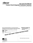
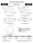
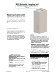
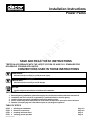
Installation Instructions
Power Packs
SAVE AND READ THESE INSTRUCTIONS
TESTED IN ACCORDANCE WITH THE LATEST EDITION OF ANSI Z21.1 STANDARD FOR
HOUSEHOLD COOKING APPLIANCES.
CONVENTIONS USED IN THESE INSTRUCTIONS
WARNINGS:
Must be followed carefully to avoid personal injury.
IMPORTANT:
Must be followed carefully to avoid damage.
NOTES:
Contain helpful hints and tips to facilitate the installation.
IMPORTANT
1.
2.
3.
4.
5.
Before beginning installation, please thoroughly read and become familiar with these instructions.
Installation and service must be completed by a qualified installer or service agency.
Installer: Please leave these Installation Instructions with the owner.
Owner: Please keep these instructions for local electrical inspector’s use and for future reference.
Read the accompanying Use & Care Manual prior to operating this appliance.
TABLE OF STEPS
STEP
STEP
STEP
STEP
1
2
3
4
Planning the installation
Electrical connections
Installing the Power Pack
Verifying proper operation
Part No. 65278 Rev. A
Page
Page
Page
Page
2-3
4-5
5
5
WARNINGS:
TO REDUCE THE RISK OF FIRE, ELECTRIC SHOCK, OR INJURY TO PERSONS, OBSERVE THE
FOLLOWING:
a) Use this unit only in the manner intended by the manufacturer. If you have questions, contact
the manufacturer.
b) Before servicing or cleaning unit, switch power off at service panel and lock the service
disconnecting means to prevent power from being switched on accidentally. When the service
disconnecting means cannot be locked, securely fasten a prominent warning device, such as a
tag, to the service panel. Exception: The additional safety instructions do not apply to a ceilingsuspended fan.
c) Installation work and eletrical wiring must be done by a qulified person(s) in accordance with all
applicable codes and standards, including fire-rated construction.
d) Sufficient air is needed for proper combustion and exhasuting of gases through the flue
(chimney) of fuel burning euipment to prevent back drafting. Follow the heating equipment
manufacturer’s guideline and safety standards such as those published by he national Fire
Protection Association (NFPA), and the American Society for Heating, Refrigeration and Air
Conditioning Engineers (ASHRAE), and the local code authorities.
e) When cutting or drilling into wall or ceiling, do not damage electrical wiring and other hidden
utilities.
f) Duct fans must always be vented to the outdoors.
CAUTION
For general ventilating use only. Do not use to exhaust hazardous or explosive materials and
vapors.
WARNINGS:
TO REDUCE THE RISK OF A RANGE TOP GREASE FIRE:
a) Never leave surface units unattended at high settings. Boilovers cause smoking and greasy
spillovers that may ignite. Heat oils slowly on low or medium settings.
b) Always turn hood ON when cooking at high heat or when cooking flaming foods.
c) Clean ventilating fans frequently. Grease should not be allowed to accumulate on fan or filter.
d) Use proper pan size. Always use cookware appropriate for the size of the surface element.
WARNINGS:
TO REDUCE THE RISK OF INJURY TO PERSONS IN THE EVENT OF A RANGE TOP GREASE FIRE,
OBSERVE THE FOLLOWING:a
a) SMOTHER FLAMES with a close-fitting lid, cookie sheet, or metal tray, then turn off the burner.
BE CAREFUL TO PREVENT BURNS. If the flames do not go out immediately, EVACUATE AND
CALL THE FIRE DEPARTMENT.
b) NEVER PICK UP A FLAMING PAN - You may be burned.
c) DO NOT USE WATER, including wet dishcloths or towels - a violent steam explosion will result.
d) Use an extinguisher ONLY if:
1) You know you have a Class ABC extinguisher, and you already know how to operate it.
2) The fire is small and contained in the area where it started.
3) The fire department is being called.
4) You can fight the fire with your back to an exit.
a
Based on “Kitchen Fire Safety Tips” published by NFPA.
Page 1
CAUTIONS:
1. To reduce the risk of fire and to properly exhaust air the power pack must be exhausted to
outside air. Never exhaust into a wall, an attic or a concealed area in the building. This can
create a potential hazard.
2. Consult a licensed ventilation contractor or qualified technician for proper installation of
exhaust ducting.
3. Locate the cooking area for minimum cross drafts – away from doors and windows, when
possible.
4. Ducts must be of adequate size and duct runs should be as short and straight as possible.
Where turns are necessary, keep turning radius as large and smooth as possible.
5. The ducting must be air tight. Use a minimum of 2 sheet metal screws at every duct joint. Then,
seal the duct joints with a high quality duct tape.
6. Only use ductwork constructed of materials deemed acceptable by state, municipal and local
codes.
STEP 1
Installation Planning
The Dacor Power Packs are designed for installation inside custom hood canopies. Proper installation of the Power Pack is directly related to
the custom canopy material construction. Closely follow the warnings concerning the instatlltion of the Power Pack within a combustible and
non-combustible hood canopy.
A qualified technician must complete the installation of this appliance.
Plan the installation so that all minimum clearances are met or exceeded. Dimensions shown provide minimum clearances, unless otherwise
noted.
WARNINGS:
1. Power packs installed in custom hood canopies, which are contructed of combustible materials,
must be installed with the combustible material structure a minimum of 36 inches above the
appliance burner surface.
2. Power packs installed in custom hood canopies, which are contructed of non-combustible
materials, must be installed with the non-combustible material structure a minimum of 30 inches
above the appliance burner surface.
3. Power packs installed in custom hood canopies, which are contructed utilizing the Dacor IHL
Stainless Steel Hood Liner, must be installed with the non-combustible material structure a
minimum of 30 inches above the appliance burner surface.
4. Follow all instructions regarding minimum safe clearances and installation location. Failure to
do so may reault in a fire or safety hazard.
5. To reduce the risk of fire use only metal duct work.
NOTE:
1. All dimensional tolerances are + 1/16”, - 0” unless otherwise stated.
MEASUREMENTS
SPECIFICATIONS
Overall Blower Chassis Width
Overall Blower Chassis Depth
Overall Blower Chassis Height
Duct Diameter
Electrical Supply Requirements
Maximum Duct Length
Total Connected Load
Blower Rating
Approximate Shipping Weight
IVS1/IVSR1 - 22 5/8" (575mm)
IVS2/IVSR2 - 34 1/2" (876mm)
12 1/4" (311mm)
6" (152mm)
IVS1/IVSR1 - 8" (203mm)
IVS2/IVSR2 - 2 x 8" (203mm)
120VAC, 60Hz, 15A
Maximum 60 Equivalent Straight Feet
1.4kW (12A)
IVS1 - 600 CFM IVS2 - 1200 CFM
IVS1/IVSR1 - 24 pounds IVS2/IVSR2 - 32 pounds
Table 1: IVS Specifications
Page 2
STEP 1 (Continued)
Installation Planning
Equal
��
Equal
CL
CL
6 1/2"
(165mm)
Equal
6 1/8"
(156mm)
��
12 1/4"
(311mm)
6 1/2"
(165mm)
CL
Equal
6 1/8"
(156mm)
CL
12 1/4"
(311mm)
22 5/8" (575mm)
34 /12" (876mm)
8" Round collar
8" Round collars
Figure 1:
IVS1/IVSR1 Overall Dimensions
Top View
Figure 2:
IVS2/IVSR2 Overall Dimensions
Top View
10" Round
12"
(305mm)
21"
(533mm)
8"
(203mm)
Figure 3:
ATD10 Overall Dimensions
Isometric View
NOTES:
1. Dacor transition model number ATD10 shown in figure 3 is available from your local Dacor
dealer.
2. Power Packs are effective when installed with 60 equivalent straight feet of ducting.
3. Power Packs ship with a back-draft damper installed in the collar of the unit.
4. Always install these products with an approved wall or roof cap.
5. Duct performance is achieved by using round duct instead of rectangular.
6. If multiple elbows are used, ensure that there is a minimum of 24 inches of straight duct between
any two elbows.
7. Avoid “S” or back to back configurations caused by adjacent elbows.
8. Thermal breaks, such as a short section of non-metallic duct, should be used in areas of
extreme cold.
9. Do not use flexible metal duct.
10. Do not use ductwork that is smaller in cross-sectional area than the recommended size duct.
11. Do not rely on duct tape alone to seal duct joints. Use sheet metal screws as required to
support the duct.
12. The Power Pack must be removable if service is required.
13. Be certain that the ductwork does not interfere with floor joists or wall studs.
8" (203mm) Round x 2" (51mm) High
with back draft damper
8" (203mm) Round x 2" (51mm) High
with back draft damper
Mounting Holes
(typ. all sides)
Electrical
Access
Mounting Holes
(typ. all sides)
21 1/4"
(540mm)
22 5/8"
(575mm)
Electrical
Access
6"
(152mm)
11 1/16"
(281mm)
12 1/4"
(311mm)
33 1/4"
(845mm)
34 1/2"
(876mm)
Figure 4:
IVS1/IVSR1 Overall Dimensions
Isometric View
6"
(152mm)
11 1/16"
(281mm)
12 1/4"
(311mm)
Figure 5:
IVS2/IVSR2 Overall Dimensions
Isometric View
Page 3
STEP 2
Electrical Connection
WARNINGS:
1. Ensure that the power supply is disconnected before proceeding.
2. Verify that the power supply matches the ratings found on the appliance data plate before
proceeding.
3. The complete appliance must be properly grounded at all times when electrical power is applied.
4. Do not ground the appliance with the neutral (white) house supply wire. A separate ground wire
must be utilized.
5. If aluminum house supply wiring is used, splice the appliance copper wires to the aluminum
house wiring with special connectors designed and agency-certified for this purpose. Follow the
connector manufacturer’s recommended procedure carefully. Improper connection can result in
a fire hazard.
6. Failure to complete electrical connections properly may result in a damaged or non-functional
system. Follow the wiring diagrams carefully to ensure a proper installation.
It is the owner’s responsibility to ensure that a qualified electrician performs the electrical connection of this appliance. The electrical
installation, including minimum supply wire size, must comply with the National Electric Code ANSI/NFPA 70-1990* (or to the latest revision)
and local codes and ordinances.
*A copy of this standard may be obtained from:
National Fire Protection Association
1 Batterymarch Park
Quincy, Massachusetts 02269-9101
NOTES:
1. The power pack systems requires a properly grounded, 120 VAC, 60 Hz., 15 Amp electrical
service.
2. Maximum full line load is 8 amps.
3. Always use a dedicated circuit.
IVS
ILB
L1
BLK
N1
WHT
Gnd
GRN
120VAC, 60Hz, 15A
Supply power from
dedicated circuit breaker
BLK
L2
BLK
WHT
N2
WHT
GRN
Gnd
GRN
IVS
L2
N2
Gnd
Figure 6:
IVS Wiring Diagram
IVS
L1
BLK
N1
WHT
Gnd
GRN
L2
BLK
N2
WHT
Gnd
GRN
120VAC, 60Hz, 15A
Supply power from
dedicated circuit breaker
REMP
Figure 8:
IVS with REMP Wiring
Diagram
Page 4
L2
BLK
N2
WHT
Gnd
GRN
L1
BLK
N1
WHT
Gnd
GRN
L2
BLK
N2
WHT
Gnd
GRN
120VAC, 60Hz, 15A
Supply power from
dedicated circuit breaker
Figure 7:
IVS with ILB Wiring Diagram
STEP 2
Electrical Connection
IVSR
ILB
BLK
L2
BLK
L1
WHT
BLK
N2
WHT
N1
WHT
Gnd
GRN
GRN
Gnd
GRN
120VAC, 60Hz, 15A
Supply power from
dedicated circuit breaker
IVS
L1
BLK
N1
WHT
Gnd
GRN
120VAC, 60Hz, 15A
Supply power from
dedicated circuit breaker
L2
BLK
N2
WHT
Gnd
GRN
REMP
L2
BLK
N2
WHT
Gnd
GRN
Figure 10:
IVSR with REMP Wiring Diagram
Figure 9:
IVSR with ILB Wiring Diagram
L2
BLK
N2
WHT
Gnd
GRN
ILB
BLK
L2
BLK
WHT
N2
WHT
GRN
Gnd
GRN
IVSR
L1
BLK
N1
WHT
Gnd
GRN
120VAC, 60Hz, 15A
Supply power from
dedicated circuit breaker
J-BOX
L2
BLK
N2
WHT
Gnd
GRN
REMP
Figure 11:
IVSR with ILB and REMP Wiring Diagram
L2
BLK
N2
WHT
Gnd
GRN
Step 3
Installing the IVS
Mount the IVS using screws (supplied by others) which are installed through the finish trim into the hood liner material. For approximate hole
locations refer to figures 4 and 5.
Step 4
Verifying Proper Operation
1.
2.
3.
Turn on the power supply at the circuit breaker.
Turn ventilator control on. Adjust the blower speed and test for affective draw.
Turn on the variable control light switch and verify lights operate correctly.
NOTE:
If the power pack does not operate properly, follow these troubleshooting steps:
1. Verify that power is being supplied to the power pack.
2. Check the electrical connections to ensure that the installation has been completed correctly.
3. Repeat the above tests.
4. If the appliance still does not work, contact an authorized DACOR service company at
(800) 772-7778, or at www.dacor.com. Do not attempt to repair the appliance yourself.
5. DACOR is not responsible for service required to correct a faulty installation.
Page 5
Web Site:
www.dacor.com
For a Dealer/Service: (800) 772-7778
Corporate Phone:
(800) 793-0093