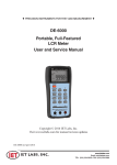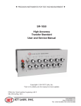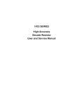
1
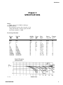
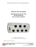
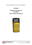
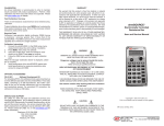
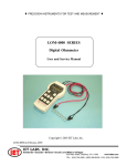
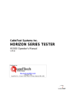
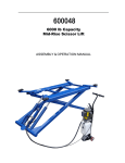
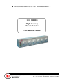
♦ PRECISION INSTRUMENTS FOR TEST AND MEASUREMENT ♦
1433 SERIES
High-Accuracy
Decade Resistor
User and Service Manual
IET LABS, INC.
formerly manufacturer by
GenRad
www.ietlabs.com
534 Main Street, Westbury, NY 11590
TEL: (516) 334-5959 • (800) 899-8438 • FAX: (516) 334-5988
To navigate our easy to use website for quick access to specifications and prices:
1. Select Find a Product to go to a convenient scrolling thumbnail catalog and then to detailed data
sheets as desired; or:
2. Select STANDARDS DECADES STROBES for products formerly manufactured by GenRad (General
Radio) or QuadTech.
Since 1976, IET labs has had a long-standing commitment to conform the instruments and standards we
offer to the customer’s needs rather than to have the customer settle for what is available. We devote our
customer service and applications entirely to the customer’s satisfaction in the quality standards, test instruments and calibration service we provide.
• Combinations of functions, special ranges, ratings, or accuracies.
• Replacement for discontinued models from other manufacturers.
• Calibration and repair services - NIST traceable.
• Compliant with ISO 9001, ISO 17025, ANSI Z540-1-1994, and MIL-STD-45662A.
Capabilities
• R: 20 µΩ-1 TΩ
• C: <1 pF - 1 F
• L: 100 µH-100 H
•
•
•
•
•
Accuracy to 1 ppm
Resolution to 0.1 ppm
Voltage to 20 kV
Power to over 1000 W
Programmable IEEE-488 or BCD
The World Standard in Metrology
Since 1915
Now continuing the GenRad tradition
Featuring instruments formerly
manufactured by
GenRad/General Radio/QuadTech
♦ PRECISION INSTRUMENTS FOR TEST AND MEASUREMENT ♦
1433 SERIES
High-Accuracy
Decade Resistor
User and Service Manual
Copyright © March, 2006 IET Labs, Inc.
1433 im/March,2006
IET LABS, INC.
formerly manufacturer by
GenRad
www.ietlabs.com
534 Main Street, Westbury, NY 11590
TEL: (516) 334-5959 • (800) 899-8438 • FAX: (516) 334-5988
WARRANTY
We warrant that this product is free from defects in material and workmanship and, when properly used, will
perform in accordance with applicable IET specifications. If within one year after original shipment, it is found
not to meet this standard, it will be repaired or, at the option of IET, replaced at no charge when returned to IET.
Changes in this product not approved by IET or application of voltages or currents greater than those allowed by
the specifications shall void this warranty. IET shall not be liable for any indirect, special, or consequential
damages, even if notice has been given to the possibility of such damages.
THIS WARRANTY IS IN LIEU OF ALL OTHER WARRANTIES, EXPRESSED OR IMPLIED, INCLUDING BUT NOT LIMITED TO, ANY IMPLIED WARRANTY OF MERCHANTIBILITY OR FITNESS FOR
ANY PARTICULAR PURPOSE.
iii
Contents
WARRANTY ...........................................................................................iii
WARNING ............................................................................................... v
CAUTION ................................................................................................ v
Chapter 1
INTRODUCTION .......................................................................... 1
1.1 Product Overview .................................................................. 1
1.2 Accessories Included ............................................................. 2
1.3 Accessories/Options Available ............................................... 2
Chapter 2
SPECIFICATIONS ......................................................................... 3
Chapter 3
OPERATION ................................................................................... 5
3.1 Installation .............................................................................. 5
3.2 Connections ........................................................................... 5
3.3 Dial Readout .......................................................................... 5
3.4 Principles of Operation .......................................................... 5
Chapter 4
MAINTENANCE ............................................................................ 8
4.1 Customer Service ................................................................... 8
4.2 Instrument Return .................................................................. 8
Figures
Figure 1.1 1433 Series High Accuracy Decade Resistor ........................ 1
Figure 3.1 A simplified equivalent circuit for a decade box with the low (L)
terminal tied to case ............................................................... 5
Figure 3.2 Equivalent three terminal circuit for a decade box with neither
terminal tied to case ............................................................... 6
Figure 3.3 Approximation of distributed capacitance effects .................. 7
ii
WARNING
OBSERVE ALL SAFETY RULES
WHEN WORKING WITH HIGH VOLTAGES OR LINE VOLTAGES.
Dangerous voltages may be present inside this instrument. Do not open the case
Refer servicing to qulified personnel
HIGH VOLTAGES MAY BE PRESENT AT THE TERMINALS OF THIS INSTRUMENT
WHENEVER HAZARDOUS VOLTAGES (> 45 V) ARE USED, TAKE ALL MEASURES TO
AVOID ACCIDENTAL CONTACT WITH ANY LIVE COMPONENTS.
USE MAXIMUM INSULATION AND MINIMIZE THE USE OF BARE
CONDUCTORS WHEN USING THIS INSTRUMENT.
Use extreme caution when working with bare conductors or bus bars.
WHEN WORKING WITH HIGH VOLTAGES, POST WARNING SIGNS AND
KEEP UNREQUIRED PERSONNEL SAFELY AWAY.
CAUTION
DO NOT APPLY ANY VOLTAGES OR CURRENTS TO THE TERMINALS OF THIS
INSTRUMENT IN EXCESS OF THE MAXIMUM LIMITS INDICATED ON
THE FRONT PANEL OR THE OPERATING GUIDE LABEL.
vii
1433 Series
Chapter 1
INTRODUCTION
1.1 Product Overview
The 1433 Decade Resistors are a family of instruments providing a very broad choice of high-performance resistance sources. Any number of decades
from one to eleven is available.
The 1433 is a precision resistance source with excellent characteristics of stability, temperature coefficient, power coefficient, and frequency response.
There are over 30 models available covering a wide
resistance range from 1 mΩ to over 111 MΩ. The
1433 Series employs stable very low resistance
switches with silver alloy contacts. A special design
keeps zero-resistance to less than 1 mΩ per decade.
Self-cleaning keeps the silver contacts from becoming tarnished when unused, or when only low currents are passed through them. This is most often the
case when only minute test currents are drawn by
digital multimeters or other test instruments. Contact
resistance is stable and remains low and repeatable.
The dials, labeled 0 to X(=10), offer smooth rotation
from position to position with no stops. Each dial has
the overlap X(10) position for maximum convenience
and flexibility in setting and adjusting resistance values. The resistance per step and maximum current of
each dial are clearly shown on the front panel. Electrical shielding is provided by an attractive aluminum
cabinet and front panel. The resistance elements have
no electrical connection to the cabinet and panel; a
separate shield terminal is provided.
High-quality gold-plated tellurium-copper binding posts
serve to minimize the thermal emf effects which can
introduce errors into dc resistance measurements. All
INTRODUCTION
other conductors within the instrument, as well as the
solder employed, contain no metals or junctions that
contribute to thermal emf problems.
With a resolution as low as 1 mΩ and a maximum
available resistance of over 111 MΩ, the 1433 series
may be used for exacting precision measurement applications requiring high accuracy, good stability, and
low zero-resistance. They can be used as components of dc and ac bridges, for calibration, as transfer
standards, and as RTD simulators.
The 1433 Series may be rack-mounted to serve as
components in measurement and control systems.
This series is part of a family of resistance substituters suited to fill many engineering and testing needs.
Consult IET for:
High-power substituters - up to 400 W
High-resistance substituters - to 1 TΩ
RTD simulators
Laboratory-standard-grade substituters - to 1 ppm
accuracy
Programmable substituters - IEEE-488 or BCD.
Figure 1.1. 1433 Series High Accuracy Decade
Resistor
1
1433 Series
1.2 Accessories Included
1.3 Accessories/Options Available
Table 1-3
Item
Instruction Manual
Calibration Certificate
2
Table 1-4
Quantity
1
1
Item
Rack Mount Kit for 4 dial units
Rack Mount Kit for 5 dial units
Rack Mount Kit for 6 dial units
Rack Mount Kit for 7 dial units
Part Number
1433-50
1433-51
1433-52
1433-53
INTRODUCTION
1433 Series
Chapter 2
SPECIFICATIONS
Range:
1 mΩ to 111.111.111.110 Ω in 1 mΩ steps.
Overall Accuracy:
The difference between the resistance at any
setting and at the Zero setting is equal to the indicated value ± (0.01% + 2 mΩ)
Decade Specifications
R/step
Ω)
(Ω)
Total R
Ω)
(Ω)
Stability
ppm/yr
L/step
(µ
µ H)
Max
Input
Power
Tempco
/step (W) ppm/oC
0.001
0.01
0.1
1
10
100
1,000
10,000
100,000
1,000,000
10,000,000
0.01
0.1
1
10
100
1000
10,000
100,000
1,000,000
10,000,000
100,000,000
500
500
50
20
20
20
20
20
20
20
20
0.01
0.1
0.15
0.55
5
15
75
-
5A
4A
1.6 A
800 mA
250 mA
80 mA
23 mA
7 mA
2.3 mA
0.7 mA
0.23 mA
0.025
0.16
0.25
0.6
0.6
0.6
0.5
0.5
0.5
0.5
0.1
50
20
20
20
15
5
5
5
5
10
10
Typical Frequency
Characteristics:
Rev 3-23-06
SPECIFICATIONS
3
1433 Series
Typical Value of Zero Impedance:
Zero Resistance (Ro):
0.001 Ω/decade at dc; 0.04 Ω/decade at
1 MHz; proportional to square root of frequency above 100 kHz.
Zero Inductance (Lo):
0. 1 µH/decade + 0.2 µH.
Effective Shunt Capacitance (C):
Value is determined largely by the highest
decade in use. With the low terminal connected to the shield, a value of 15 to 20 pF/
decade may be assumed, counting decades
down from the highest. Thus, if the third decade from the top is the highest resistance, a
value of 45 to 60 pF may be assumed. If the
highest decade in the unit is in use, the effective capacitance is 15 to 20 pF, regardless of
the settings of the lower-resistance decades.
Switches:
Continuous rotation; solid silver-alloy contacts;
contact resistance of less than 1 mΩ; capacitance
of less than 1 pF between contacts; lifetime in
excess of 1 million cycles.
Maximum voltage to case:
2000 V peak
Terminals:
Gold plated, tellurium-copper, low-thermal-emf
binding posts on standard 3/4 inch spacing; shield
terminal provided.
Mechanical:
Dimensions: in inches (mm)
Weight: in lb (kg)
4 dial
5 dial
6 dial
7 dial
L
12.3 (312)
14.8 (375)
17.3 (439)
17.3 (439)
Environmental:
Operating:
Storage:
W
3.5 (89)
3.5 (89)
3.5 (89)
5.3 (135)
D
5.0 (127)
5.0 (127)
5.0 (127)
5.0 (127)
Wt
3.5 (1.6)
4.0 (1.8)
4.5 (2.0)
6.0 (2.7)
+10 to +40oC, <80% RH
-20 to +65oC
Supplied with unit:
Instruction manual
Calibration Certificate
Accessories available:
1433-50 Rack Mount Kit for 4-dial units
1433-51 Rack Mount Kit for 5-dial units
1433-52 Rack Mount Kit for 6-dial units
1433-53 Rack Mount Kit for 7-dial units
Ordering Information:
Catalog
No.
1433-01
1433-00
1433-02
1433-04
1433-06
1433-08
1433-09
1433-09A
1433-10
1433-12
1433-14
1433-16
1433-18
1433-18A
1433-19
1433-20
1433-22
1433-24
1433-26
1433-27
1433-28
1433-29
1433-31
1433-33
1433-34
1433-35
1433-36
1433-37
1433-38
1433-39
1433-39A
1433-39B
1433-40A
1433-40
1433-41
Total
Ω)
(Ω
1.11
111.1
1,111
11,110
111,100
1,111,000
11,110,000
111,100,000
1,111.1
11,111
111,110
1,111,100
11,111,000
111,110,000
1,111.11
11,111.1
111,111
1,111,110
11,111,100
111,111,000
11,111.11
111,111.1
1,111,111
11,111,110
111,111,100
111,111.110
1,111,111.10
11,111,111.0
111,111,110
1,111,111.11
11,111,111.1
111,111,111
11,111,111,110
111,111,111.1
111,111,111.11
Ohms
/step
0.001
0.01
0.1
1
10
100
1000
10,000
0.01
0.1
1
10
100
1000
0.001
0.01
0.1
1
10
100
0.001
0.01
0.1
1
10
0.001
0.01
0.1
1
0.001
0.01
0.1
0.001
0.01
0.001
No.
of dials
3
4
4
4
4
4
4
4
5
5
5
5
5
5
6
6
6
6
6
6
7
7
7
7
7
8
8
8
8
9
9
9
10
10
11
Rev 3-23-06
4
SPECIFICATIONS
1433 Series
Chapter 3
OPERATION
3.1 Installation
All models of the 1433 Decade Resistor are supplied as bench instruments but may be rack mounted.
Installation in a standard 19-inch rack requires a Rack
Mount Kit whose part number depends on the number of dials on the unit. Refer to paragraph 1.3
3.2 Connections
The terminals on the front panel of the 1433 are standard 3/4-inch-spaced binding posts that accept banana plugs, phone plugs, spade lugs, various clips, and
wire sizes up to No. 12. The high (H) and low (L)
binding posts are insulated from the panel and used
for regular two-terminal applications. For grounded
operation, connect the shorting link between the ground
(G) terminal and the low (L) terminal. Refer to paragraph 3.4 for a detailed comparison of two- and threeterminal connections.
If switches have not been operated for an extended
period, they should be rotated a few times to restore
contact resistance to specifications.
3.3 Dial Readout
All 1433 decades have easy-to-read dials with numbered steps from 0 to X (= 10). When setting the
decade switches, observe the decimal point on the
panel and remember that X equals ten units. For example, the five dial Model 1433-10 is set for a value
of 54.3 Ω by setting the decade switches as follows:
0 5 4 . 3 0 = 54.3 Ω
or
0 5 4 . 2 X = 54.3 Ω
OPERATION
Note that X, in the above example, is equal to a value
of ten 0.01 W units in that decade, or one 0.1 Ω unit
in the next decade to the left.
The following examples illustrates the result of setting all decades in the 1433-10 to X.
Dial setting:
X X X . X X
Resistance value:
1 1 1 1 . 1 0 Ω
3.4 Principles of Operation
The best approximation of a complete equivalent circuit
for a 1433 Decade Resistor is shown in Figure 3-1.
Figure 3-1. A simplified equivalent circuit for a
decade box with the low (L) terminal tied to case
In Figure 3-1:
R = setting of the decade box.
L =LO= N1 ∆ L1 + N2 ∆ L2 + ....
where Lo ≈ 0.1 µH per decade x number of decades
in unit + 0.2 µH.
∆ L1, ∆ L2,....... ≈ L/step values from specifications.
N1, N2,... ≈ settings of corresponding decades.
C=Co+MC1
where CO≈ 15 pF
C1≈ 20 pF
M = number of unused decades (set to zero)
preceding first decade used.
5
1433 Series
The phase angle (Q) for this circuit is:
Q≈ω(L/R - RC).
At low values of R, the L/R term is dominant; at high
values of R, the RC term is more important.
The effective series resistance is:
R
Rs =
1+ω2R2C2
The effective parallel resistance is:
ω2 L2
Rp = R 1+ 2
R
(
)
At low values, the series resistance remains constant to
rather high frequencies because inductance has no effect
on Rs. At very low values, skin effect increases Rs.
At high values, the series resistance falls off rather
rapidly with frequency because of capacitance. The
parallel resistance, however, is not affected by the
lumped capacitance shown in the simple equivalent
circuit (see Figure 3-1). The parallel value is affected
by distributed capacitance and dielectric loss not
shown. An approximate equation that considers these
effects on Rp is:
Rp ≈ R[1+
ω2 L2
- ωR10-3- 4ω2R210-24-25ω2RRy10-24]
R2
Figure 3-2. Equivalent three terminal circuit for a
decade box with neither terminal tied to case
In Figure 3-2:
R = setting of the decade box.
L = LO = N1 ∆L1 + N2 ∆L2+ ....
where Lo ≈ 0.1 µH per decade x number of decades in unit + 0.2 µH.
∆ L1, ∆ L2, ... ≈ L/step values from specifications.
N1, N2, ... ≈ settings of corresponding decades.
Ca = l0 Ma + 8 pF
where Ma = number of unused decades (set to zero)
preceding first decade used.
Cb = 20 Mb + 20 pF
where Mb = number of unused decades (set to zero)
preceding first decade used.
Cs = 2 pF
The ωR10-13 term represents dielectric loss, the next
term represents distributed capacitance in the first
decade used (not zero), and the last term represents
distributed capacitance in the first decade if it is not
used (set to zero), where Ry is the total possible value
of that decade. (The last term is not used if the first
decade is not set to zero). When the case is not tied
to either terminal, the decade resistor becomes a
three-terminal circuit as shown in Figure 3-3.
6
OPERATION
1433 Series
There is also some distributed capacitance (Cd) from
the resistor to the case, as shown in Figure 3-3. This
capacitance has the effect of increasing the effective inductance by an amount of approximately
N3R2C x 10-3: where N is the setting of the first used
(not zero) decade, R is the total value of the decade
resistor, and C is 2 pF.
Figure 3-3. Approximation of distributed
capacitance effects
OPERATION
7
1433 Series
Chapter 4
MAINTENANCE
4.1 Customer Service
4.2 Instrument Return
The IET warranty attests to the quality of materials
and workmanship in our products. For application
assistance or if difficulties occur, our engineers will
assist in any way possible. If you cannot eliminate
the difficulty, please e-mail, FAX, or phone our Service Department, giving full information of the trouble
and of steps taken to remedy it. Be sure to include
the type and serial number of the instrument.
Before returning an instrument to IET for service
please call our Service Department at 800-899-8438
for Return Material Authorization (RMA). Include a
Purchase Order Number to insure expedient processing. Units under warranty will be repaired at no
charge. For any questions on repair costs or shipment instructions, please contact our Service Department at the above number. To safeguard an instrument during shipment, please use packaging that
is adequate to protect it from damage, (i.e., equivalent to the original packaging) and mark the box “Delicate Electronic Instrument”. Return material should
be sent freight prepaid to:
In the U. S. call
617-969-0804 for technical support
800-899-8438 or 516-334-5959 for customer service
516-334-5988 for FAX
www.ietlabs.com
IET Labs, Inc.
10 Dedham Street
Newton, MA 02461
Attention: Service Department
8
MAINTENANCE
IET LABS, INC.
Standards • Decades • Strobes • Sound Level Meters • Bridges
Formerly manufactured by
GenRad
534 Main Street, Westbury, NY 11590
TEL: (516) 334-5959 • (800) 899-8438 • FAX: (516) 334-5988
www.ietlabs.com
IET LABS, INC.
Standards • Decades • Strobes • Sound Level Meters • Bridges
Formerly manufactured by
GenRad
534 Main Street, Westbury, NY 11590
TEL: (516) 334-5959 • (800) 899-8438 • FAX: (516) 334-5988
www.ietlabs.com