1
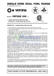
DOMINO HOBS
C621 & C721
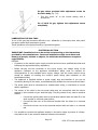
INSTALLATION AND OPERATING
INSTRUCTION BOOKLET
IMPORTANT: You must read this instruction Book before
installing or using this appliance and retain it for future use.
Caple Products
Telephone 0870 2411142
Facsimile 0117 982 6878
Page 1
C621 C721 user manual.DOC
The manufacturer cannot be held responsible for possible inaccuracies due to printing or transcription
errors in this booklet. The manufacturer reserves the right to make all modifications to its products
deemed necessary for manufacture or commercial reasons at any moment and without prior notice,
without jeopardising the essential functional and safety characteristics of the appliances.
Dear Customer
Thank you for purchasing our product. The safety precautions and recommendations
reported below are for your own safety and that of others. They will also provide a means
by which to make full use of the features offered by your appliance.
Please preserve this booklet carefully. It may be useful in future, either to yourself or to
others in the event that doubts should arise relating to its operation.
This appliance must be used only for the task it has explicitly been designed for,
that is for cooking foodstuffs. Any other form of usage is to be considered as
inappropriate and therefore dangerous.
The manufacturer declines all responsibility in the event of damage caused by
improper, incorrect or irrational use of the appliance.
IMPORTANT PRECAUTIONS AND RECOMMENDATIONS
• After having unpacked the appliance, check to ensure that it is not damaged. If you
have any doubts, do not use it and consult your supplier or a professionally qualified
technician.
• Packing elements (i.e., plastic bags, polystyrene foam, nails, packing straps, etc.) should
not be left around within easy reach of children, as these may cause serious injuries.
• The packaging material is recyclable and is marked with the recycling symbol
• Do not attempt to modify the technical characteristics of the appliance as this may
become dangerous to use.
• The manufacturer cannot be considered responsible for damage caused by unreasonable,
incorrect or rash use of the appliance.
• If you should decide not to use this appliance any longer (or decide to substitute with a
newer model), before disposing of it, it is recommended that it be made inoperative in an
appropriate manner in accordance to health and environmental protection regulations,
ensuring in particular that all potentially hazardous parts be made harmless, especially in
relation to children who could play with old appliances.
• The appliance should be installed and all the gas/electrical connections made by a
qualified engineer in compliance with local regulations in force and following the
manufacturer's instructions
TIPS FOR THE USER
• During and after use of the cook top, certain parts will become very hot. Do not touch
hot parts.
Keep children away from the cooking hob when it is in use.
• After use, ensure that the knobs are in position • (off), and close the main gas delivery
valve or the gas cylinder valve.
• In case of difficulty in the gas taps operation, call Service.
• Before any cleaning or maintenance, switch off the electricity to the cook top.
•
Page 2
C621 C721 user manual.DOC
Do not leave inflammable material on the cook top.
• Make sure that the electrical cables of other appliances installed nearby cannot come
into contact with the cook top.
• Never cook the food directly on the electric hotplates, but in suitable pans or containers.
•
IMPORTANT PRECAUTIONS AND RECOMMENDATIONS FOR USE OF ELECTRICAL
APPLIANCES
Use of any electrical appliance implies the necessity to follow a series of fundamental rules.
In particular: • Never touch the appliance with wet hands or feet;
• Do not operate the appliance barefooted;
• Do not allow children or disabled people to use the appliance without your supervision.
The manufacturer cannot be held responsible for any damages caused by improper,
incorrect or unreasonable use of the appliance.
DECLARATION OF CE CONFORMITY
These instructions are only valid for use in the UK.
This cooking hob has been designed to be used only for cooking. Any other use (such as
heating a room) is improper and dangerous.
This cooking hob has been designed, constructed, and marketed in compliance with:
Safety requirements of the "Gas" Directive 90/396/EEC;
Safety requirements of EEC Directive "Low voltage" 73/23 (gas or gas/electric appliances);
Safety requirements of EEC Directive "EMC" 89/336 (gas or gas/electric appliances);
Requirements of EEC Directive 93/68.
FEATURES
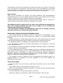
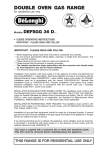
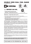
“2 GAS" COOKING HOB (Fig. 1.1)
The appliance has class 3
1. Semi rapid burner (SR) - 1,75 kW
2. Rapid burner (R) - 3,00 kW
3. Burner 2 (R) control knob
4. Burner 1 (SR) control knob
5. Electric gas-lighting pushbutton.
CAUTION:
•
If the burner is accidentally extinguished, turn the gas off at the control knob and wait
at least 1 minute before attempting to relight,
•
Gas hobs produce heat and humidity in the environment in which they are installed.
Ensure that the cooking area is well ventilated by opening the natural ventilation grilles
or by installing an extractor hood connected to an outlet duct.
•
If the hob is used for a prolonged time it may be necessary to provide further ventilation
by opening a window or by increasing the suction power of the extractor hood (if fitted).
Page 3
C621 C721 user manual.DOC
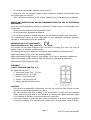
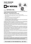
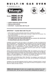
" 2 ELECTRIC" COOKING HOB (Fig. 1.3)
Electrical insulation Class I.
Overheating surfaces protection Type Y.
1. Electrical plate Q) 145 - (1000 W - 1500 W)
2. Electrical plate 0 180 - (1500 W - 2000 W)
3. Electrical plate 1 control knob
4. Electrical plate 2 control knob
5. Power indicator light
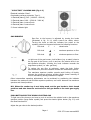
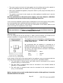
GAS BURNERS
Gas flow to the burners is adjusted by turning the knobs
(illustrated in fig. 2.1 b) which control the safety valves.
Turning the knob so that the indicator line points to the
symbols printed on the panel achieves the following functions:
Full circle
•
=
closed valve
Full circle
=
maximum aperture or flow
Full circle
=
minimum aperture or flow.
To light one of the gas burners, hold a flame (e.g. a match) close to
the top part of the burner, push in and turn the relative knob in an
anti-clockwise direction, pointing the knob indicator towards the
large flame symbol (i.e. max. gas flow).
To reduce the gas flow to minimum, rotate the knob further
anti-clockwise to point the indicator towards the small flame symbol.
The maximum aperture position permits rapid boiling of liquids,
whereas the minimum aperture position allows slower warming of
food or maintaining boiling conditions of liquids.
Other intermediate operating adjustments can be achieved by positioning the indicator
between the maximum and minimum aperture positions, and never between the maximum
aperture and closed positions.
N.B. When the cooker top is not being used, set the gas knobs to their closed
positions and also close the cock valve on the gas bottle or the main gas supply
line.
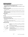
PUSH BUTTON ELECTRIC SPARK-LIGHTING GAS
To light one of the burners you have to push in and turn the relative knob to the maximum
aperture position (large flame symbol) and press the electric lighter button (fig. 2.2) until
the flame has been lit.
Adjust the gas valve to the desired position.
Page 4
C621 C721 user manual.DOC
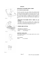
CHOICE OF BURNER (fig. 2.4)
The symbols printed on the panel beside the gas knobs indicate the correspondence
between the knob and the burner. The most suitable burner is to be chosen according to the
diameter and volume capacity of the container to be warmed. It is important that the
diameter of the pots or pans suitably match the heating potential of the burners in order not
to jeopardize the efficiency of the burners, bringing about a waste of gas fuel. A small
diameter pot or pan placed on a large burner does not necessarily mean that boiling
conditions are reached quicker.
DIAMETERS OF PANS WHICH MAY BE USED ON THE H OBS
BURNERS
Minimum
Maximum
12 cm
22 cm
Semi rapid
Rapid
Do not use pans with concave or convex bases
Caution!
The cooking hob becomes very hot during operation. Keep children well out of
reach.
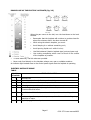
NORMAL HOTPLATE
To turn on the electric hotplate, rotate the knob (fig. 3.1 - 3.2) to
the desired setting. The numbers from 1 to 6 or 1 to 12 indicate
the operating positions with increasing number corresponding to
higher temperature settings When the pan comes to the boil, turn
the heat down to the level desired.
Remember that the hotplate will continue to produce heat for
about five minutes after it has been turned off.
RAPID HOTPLATE (red dot)
The rapid hotplate control knob is similar to that of the normal
hotplate, with 6 or 12 selectable heating positions (fig. 3.1 - 3.2).
The characteristics of this hotplate, which is also equipped with a
thermostatic cut-off device, make it possible to:
•
Achieve the cooking temperature rapidly.
•
Make full use of its output power using flat-bottomed pans
•
Limit the output power with unsuitable saucepans.
•
Never cook food directly on the electric hotplates always use a saucepan or
suitable container.
•
•
Caution! the cooling hob becomes very hot during operation.
Keep children well out of reach.
Page 5
C621 C721 user manual.DOC
PROPER USE OF THE ELECTRIC HOTPLATE (fig. 3.3)
When the pan comes to the boil, turn the heat down to the level
desired.
•
Remember that the hotplate will continue to produce heat for
about five minutes after it has been turned off.
•
While using the electric hotplate, you must:
•
Avoid keeping it on without something on it;
•
Avoid pouring liquids on it while it is hot;
•
Use flat-bottomed (electric hotplate type) pots and pans only
•
Use cooking receptacles which cover as much of the surface
of the hotplate as possible.
•
To save electricity, use lids whenever possible.
•
Never cook food directly on the hotplate: always use a pan or suitable container.
An indicator light located close to the control panel signals that the hotplate is operating
ELECTRIC HOTPLATE USAGE
TABLE
Position
TYPE OF COOKING
of switch
0
0
Switched OFF
1/2
1/2
For melting operations (of butter or chocolate)
2
2/3/4 To keep foods warm or heat small quantities of water.
3
4/5/6 To heat greater quantities of water and to whip creams and sauces.
3/4
6/7
Slow boiling, e.g. spaghetti, soups, boiled meats, to continue steam heating
of roast meats and stews.
4
7/8
For all kinds of fried foods, meats and steaks, cutlets and cooking without a
lid.
4
8/9/10 For browning of meat, cooked potatoes, fried fish and for boiling large
quantities of water.
6
11/12 Rapid frying, grilled steaks, etc.
Page 6
C621 C721 user manual.DOC
CLEANING AND MAINTENANCE
GENERAL RECOMANDATION
•
Before you begin cleaning you must ensure that the hob is switched off.
•
It is advisable to clean when the appliance is cold.
•
Avoid leaving alkaline or acid substances (lemon juice, vinegar etc.) on the
surfaces.
STAINLESS STEEL ELEMENTS
•
Stainless steel parts must be rinsed with water and dried with a soft and clean cloth or
with a chamois leather.
•
For difficult dirt, use a specific non-abrasive product available commercially or a little hot
vinegar.
•
Note: regular use could cause discolouring around the burners, because of the
high flame temperature.
CONTROL KNOB
•
The control knobs may be removed for cleaning but care should be taken not to damage
the seal.
GAS TAPS
•
In the event of operating faults in the gas taps, call the Service Department.
CLEANING ELECTRIC HOTPLATES
•
Always clean when the hotplate is tepid.
•
Use a soft cloth, dampened with water, and a little salt. To finish off, use a soft cloth
with a little oil.
•
Do not use water, to avoid the formation of rust.
•
Do not use steam jet cleaners because the humidity could infiltrate into the appliance
making it dangerous.
BURNERS AND GRIDS
•
These parts can be removed and cleaned with appropriate
products.
•
After cleaning, the burners and their flame distributors must be
well dried and correctly replaced.
•
It is very important to check that the burner flame distributor
and the cap has been correctly positioned - failure to do so can
cause serious problems.
•
In appliances with electric ignition keep the electrode clean so
that the sparks always strike.
•
Note: To avoid damage to the electric ignition do not use it when
the burners are not in place.
Page 7
C621 C721 user manual.DOC
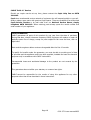
CORRECT REPLACEMENT OF THE BURNERS
It is very important to check that the burner flame distributor “F” and
the cap “C” has been correctly positioned (see figs. 5.2 and 5.6 )
failure to do so can cause serious problems. Check that the electrode
"S" (fig. 5.2) is always clean to ensure trouble-free sparking.
Check that the probe "T" (fig. 5.2) next to each burner is always clean
to ensure correct operation of the safety valves. Both the probe and
ignition plug must be very carefully cleaned.
Page 8
C621 C721 user manual.DOC
INSTALLATION ADVICE
IMPORTANT
• The appliance should be installed, regulated and adapted to function with
other types of gas by a QUALIFIED INSTALLATION TECHNICIAN.
• Failure to comply with this condition will render the guarantee invalid.
• The appliance must be installed in compliance with regulations in force.
• Installation technicians must comply to current laws in force concerning
ventilation and the evacuation of exhaust gases.
• Always unplug the appliance before carrying out any maintenance operations
or repairs
• The appliance must be housed in heat-resistant units.
• These tops are designed to be embedded into kitchen fixtures measuring 600
mm in depth.
• The walls of the units must not be higher than worktop and must be capable
of resisting temperatures of 75 °C above room temperature..
• Do not install the appliance near inflammable materials (e.g., curtains).
GAS HOBS
TECHNICAL INFORMATION FOR THE INSTALLER
Before installing the cook top, remove the protective film.
This cook top can be built into a working surface 20 to 40
mm thick and 600 mm deep.
In order to install the cooker top into the kitchen fixture, a
hole with the dimensions shown in figs. 6.1 a - 6.1 b has to be made, keeping in
consideration the following:
• Within the fixture, between the bottom side of the cooker top and the upper surface of
any other appliance or internal shelf there must be a clearance of at least 30 mm;
• The cooker top must be kept no less than 100 mm away from any side wall;
• The cooker top must be kept at a distance of no less than 50 mm from the rear wall.
• There must be a distance of at least 650 mm between the hob and any wall cupboard or
extractor hood positioned immediately above (see fig. 6.2)
•
The coatings of the walls of the unit or appliances near the cook top must be heat
resistant ("Y" protection against heating in compliance with standards EN 60335-2-6).
Do not install the appliance near inflammable materials (e.g.. curtains).
Page 9
C621 C721 user manual.DOC
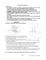
WITH CUPBOARD DOORS (fig. 6.3)
The fixture has to be made according to specific requirements in
order to prevent the gas burners from going out, even when the
flame is turned down to minimum, due to pressure changes
while opening or closing the cupboard doors.
It is recommended that a 30 mm clearance be left between the
cooker top and the fixture surface beneath it.
FASTENING THE COOKTOP (fig. 6.4)
Each cook top is supplied with a set of tabs and screws to fasten
it on units with a working surface from 2 to 4 cm deep.
The kit includes 4 tabs "A" and 4 self-threading screws "B".
• Cut the unit.
Stretch gasket "C" over the edge of the hole made, being
•
careful to overlay the junction edges.
Turn the cook top over and put tabs "A" into the mountings;
•
only tighten screws "B" a few turns. Make sure that the tabs
are mounted correctly as shown in the figure.
• Put the cook top into the hole cut into the unit and position
it correctly.
•
Put tabs "A" into place and tighten screws "B" until the cook
top is completely secured.
•
Using a sharp tool cut off the part of gasket "C" which
protrudes from the cook top.
CHOOSING
models)
SUITABLE
SURROUNDINGS
(for
gas
The room where the gas appliance is to be installed must
have a natural flow of air so that the gas can burn (in
compliance with the current laws in force).
The flow of air must come directly from one or more
openings made in the outside walls with a free area of at
least 100 cm2.
If the appliance does not have a no-flame safety
device this opening must have an area of at least 200
cm2.
The openings should be near the floor and preferably on the side opposite the exhaust for
combustion products and must be so made that they cannot be blocked from either the
inside or the outside.
When these openings cannot be made, the necessary air can come from an adjacent room
which is ventilated as required, as long as it is not a bedroom or a danger area (in
compliance with the current laws in force).
In this case, the kitchen door must allow the passage of the air.
Page 10
C621 C721 user manual.DOC
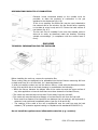
DISCHARGING PRODUCTS OF COMBUSTION
Extractor hoods connected directly to the outside must be
provided, to allow the products of combustion in the gas
appliance to be discharged (fig. 6.6).
If this is not possible, an electric fan may be used, attached to
the external wall or the window; the fan should have a capacity
to circulate air at an hourly rate of 3-5 times the total volume of
the kitchen (fig. 6.7).
The fan can only be installed if the room has suitable vents to
allow air to enter, as described under the heading "Choosing
suitable surroundings" (in compliance with the current laws in
force).
GAS HOBS
TECHNICAL INFORMATION FOR THE INSTALLER
Before installing the cook top, remove the protective film.
These cooking hobs are designed to be embedded into kitchen fixtures measuring 600 mm
in depth and from 20 to 40 mm thick, for 2 electrical plates hob.
In order to install the cooker top into the kitchen fixture, a hole with the dimensions shown
in figs. 6.8a and 6.8b has to be made, keeping in consideration the following: • Within the fixture, between the bottom side of the cooker top and the upper surface of
any other appliance or internal shelf there must be a clearance of at least 30 mm;
• The cooker top must be kept no less than 50 mm away from any side wall;
• The cooker top must be kept at a distance of no less than 50 mm from the rear wall.
• There must be a distance of at least 650 mm between the hob and any wall cupboard or
extractor hood positioned immediately above (see figs. 6.9a and 6.9b).
•
The coatings of the walls of the unit or appliances near the cook top must be heat
resistant ("Y" protection against heating in compliance with standards EN 60335-2-6).
Do not install the appliance near inflammable materials (e.g.. curtains).
Page 11
C621 C721 user manual.DOC
FASTENING THE COOKTOP
Each cooker top is provided with an installation kit including brackets and screws for
fastening the top to fixture panels from 20-30 to 40 mm thick, figs. 6.11 (2 electrical plates
hob.
•
Cut the unit.
•
Stretch gasket "D" over the edge of the hole made, being careful to overlay the junction
edges
•
Turn the cook top over and put tabs "A" (fig. 6.10) into the mountings, only tighten
screws "B" a few turns. Make sure that the tabs are mounted correctly as shown in the
figures 6.11 and 6.12. Turn the tabs so that the cook top can be put into the hole.
•
•
Put the cook top into the hole cut into the unit and position it correctly.
Put tabs "A"; into place, tooth "C" of the tabs should go into the hole.
•
Tighten screws "B" until the cook top is completely secured.
•
Using a sharp tool cut off the part of gasket "D" which protrudes from the cook top.
GAS CONNECTIONS
Make sure that the hob is adapted to function with the type of
gas supply available (see label). If not, refer to the section
headed "Adapting the appliance to function with different types of
gas".
GASES
The gases used for the operation of cooking appliances may be
grouped by their characteristics into two types:
• Liquid gas: Butane gas (G 30) and Propane gas (G 31)
•
Natural gas (G 20)
Page 12
C621 C721 user manual.DOC
Connecting to gas mains:
The cook top connection (fig. 7.1 a - 7.1 b) is made up as follows:
•
1 nipple "A"
•
1 union elbow "C"
•
gaskets "F"
•
1 conical elbow "G"
Connection to the gas main must be performed by a qualified technician, in compliance with
the current laws in force.
Before connecting the appliance to the gas main, mount conical elbow "G" (supplied with
appliance) onto the union elbow "C," upon which the gasket "F" has been placed.
To maintain the thickness of 3 cm, the hob is fitted with a channel to contain the connection
pipe.
The gas inlet union can be turned in the direction required after the union elbow C -nipple A
connection has been slackened (Fig. 7.2).
Never put it in the horizontal or vertical position.
IMPORTANT
• Never turn union C using force without first slackening nut A.
•
Gaskets F (Fig. 7.1) guarantee the seal of the gas connection.
•
Replace them whenever they are even slightly deformed or imperfect.
•
Any connection to fixed metal pipes must be done in such a way so as not to place
undue stress on the hob chassis.
•
If using flexible metal pipes, make sure they are not squashed, and do not come into
contact with moving parts.
•
Any flexible pipes must be so installed as to be easily inspected along their whole length.
They must be changed before the expiry date (printed on the pipe itself) and not exceed
2 metres in length.
•
After connecting to the gas mains, check that the couplings are correctly sealed, using
soapy solution, but never a naked flame.
ADAPTING THE APPLIANCE TO FUNCTION WITH DIFFERENT TYPES OF GAS
If a gas different from that indicated on the label is used, adapt the cook top to this new
function.
Every cooking hob is provided with a set of injectors for the various types of gas.
Injectors not supplied can be obtained from the After-Sales Service.
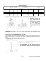
Select the injectors to be replaced according to the table below. The nozzle diameters,
expressed in hundredths of a millimeter, are marked on the body of each injector.
Page 13
C621 C721 user manual.DOC
INJECTORS TABLE
Cat II 2H3+ NOMINAL REDUCED
POWER
BURNERS
[Hs - Kw]
POWER
[Hs - Kw]
G30/G31
G20
28-30/37 mbar
20 mbar
Injector dial. Burners with
[1/100 mm] Safety valve device
Burners without
safety valve device
By-pass [1/100 mm]
By-pass [1/100 mm]
Injector dial.
[1/100 mm]
By-pass [1/100
mm]
Semi-rapid (SR) 1,75
0,45
65
30
34
97
Adjustable
Rapid (R)
3,00
0,75
85
40
44
115
Adjustable
Triple ring (TR) 3,50
1,50
95
62
65
135
Adjustable
OPERATIONS TO BE PERFORMED WHEN SUBSTITUTING THE INJECTORS
•
Remove the gratings, the
burner covers and the
knobs;
•
Using a wrench, substitute
the nozzle injectors "J"
(Fig. 7.3 - 7.4) with those
most suitable for the kind
of gas for which it is to be
used.
The burners are made in such a way so as not to require the regulation of the
primary air.
REGULATING THE BURNER MINIMUM SETTING
When switching from one type of gas to another, the minimum flow rate must also be correct: the flame should not go out even when passing suddenly from maximum to minimum
flame.
To regulate the flame follow the instructions below:
•
Light the burner
•
Set the cock valve to minimum
On gas valves provided with adjustment screw in
the centre of the shaft (fig. 7.5):
•
Using a screwdriver with max. diameter 3 mm, turn
the screw inside the tap until the correct setting is
obtained.
Page 14
C621 C721 user manual.DOC
On gas valves provided with adjustment screw on
the valve body (fig. 7.6):
•
Turn the screw "A" to the correct setting with a
screwdriver.
For G 30/G 31 gas, tighten the adjustment screw
completely.
LUBRICATING THE GAS TAPS
If one of the gas taps becomes difficult to turn, dismantle it, thoroughly clean with petrol
and apply special high-temperature grease.
These operations must be performed by a specialist engineer.
---------------------------------------------------------------------------------------------------------------ELECTRICAL SECTION
IMPORTANT: Installation has to be carried out according to the instructions
provided by the manufacturer. Incorrect installation might cause harm and
damage to people, animals or objects, for which the manufacturer accepts no
responsibility.
DETAILS
•
Connection to the electric power supply must be carried out by a qualified technician and
following the appropriate safety regulations;
•
Before carrying out the connection to the power supply, the voltage rating of the
appliance (stamped on the appliance identification plate) must be checked for
correspondence to the available mains supply voltage, and the mains electric wiring
should be capable of handling the cooker's power rating (also indicated on the
identification plate);
•
The appliance is supplied without a power supply plug and therefore if you are not
connecting directly to the mains, a standardized plug suitable for the load must be fitted.
•
The power point must be connected to a suitable earth wiring, in conformity to current
safety regulations.
•
The colours of the wires in the hob power cable may not correspond with the colours
marked on the terminals of your electrical plug. The plug should in any case be wired as
follows: o
o
o
•
Connect the green/yellow wire to the terminal marked with the letter E or the
earth symbol or coloured green/yellow;
Connect the blue wire to the terminal marked with the letter N or coloured
black;
Connect the brown wire to the terminal marked with the letter L or coloured
red.
It is possible to connect the appliance directly to the mains supply by means of a heavyduty switch with 3 mm minimum distance between the contacts.
Page 15
C621 C721 user manual.DOC
•
The power supply cord must not touch against any hot surfaces and must be placed so
that it’s temperature does not exceed 75°C at any point along it’s length.
•
After having installed the appliance, the power switch or power plug must always be in a
accessible position.
•
The appliance must have its own supply; any other appliances installed near it must be
supplied separately.
N.B. For connections to the mains power supply, never use adaptors, reductions
or multiple power points as these may overheat and catch fire.
In the event that installation should require modifications to the mains supply wiring system,
it is recommended that a qualified technician be called to carry out substitution.
The technician will also have to verify that the cross-section of the electric cables on the
power point match the appliance's power rating.
Connection to a good earth wiring system is absolutely essential.
The manufacturer accepts no responsibility for any inconvenience caused by
failure to comply with this rule.
A double pole switch must be provided no further than 2 metres from the appliance to the
electrical supply.
If you are using the hob for the first time, or after a period of disuse, you should set the
controls to position 1 for approximately 30 seconds, to dry out any humidity.
This appliance must be connected by a competent person,
using fixed wiring via a DOUBLE POLE SWITCHED
FUSED SPUR OUTLET.
We recommend that the appliance is connected by a
qualified electrician, who is a member of the N.I.C.E I C.
and who will comply with the I.E.E. and local regulations.
The wires in the mains lead are coloured in accordance
with the following code: Green & Yellow =
Earth
Blue
=
Neutral
Brown
=
Live
As the colours of the wires in the mains lead for the appliance, may not correspond with the
coloured markings identifying the terminals in your spur box, proceed as follows:
1. The wire which is coloured green and yellow must be connected to the terminal
marked E (Earth) or coloured Green.
2. The wire which is coloured blue must be connected to the terminal marked N
(Neutral), or coloured Black.
3. The wire which is coloured brown must be connected to the terminal marked L
(Live), or coloured Red.
Before carrying out any work on the electrical section of the appliance, it must be
disconnected from the mains.
Page 16
C621 C721 user manual.DOC
REPAIRS
REPLACING THE POWER SUPPLY CABLE
For 2 electrical plate model
Turn the cook top over and unhook the terminal board
cover by inserting a screwdriver into the two hooks "A" (fig.
8.1). Open the cable gland by unscrewing screw "F" (fig.
82), unscrew the terminal screws and remove the cable.
The new supply cable, of suitable type and section, is
connected to the terminal board following the diagram fig.
8.3.
REPLACING THE POWER SUPPLY CABLE (for gas
models)
The supply cable must be replaced with a cable of the
same type. - The electrical cable must be connected to the
terminal board following the diagrams of fig. 8.4.
FEEDER CABLE SECTION
GAS HOB type "H05V2V2-F"
resistance to temperatures of 90°C
230 V-
3 x 0,75 mm2
ELECTRIC HOTPLATES
The external diameter of the supply cable must not be
more than 9 mm.
type "H05RR-P'
230 V-3 x 1,50 mm2
Page 17
C621 C721 user manual.DOC
CAPLE "Built-in" Service
Should you require service at any time, please contact the Caple Help line on 0870
2411142.
Caple have a nationwide service network of engineers who will respond quickly to your call.
Always replace spare parts with genuine Caple spares. These are available from authorised
Caple Service Centers or by mail order from our National Service Stores, simply
telephone 0870 2411142. When ordering parts always quote the model number and
serial number of your appliance.
YOUR GUARANTEE
CAPLE guarantees all parts of this product for one year from the date of purchase.
During that time, should it become necessary CAPLE engineers will replace or repair all
defective parts free of charge, except for parts subject to fair wear and tear, such as
light bulbs.
Parts and the engineers labour costs are chargeable after the first 12 months.
To qualify for benefits under the guarantee, you must be able to provide proof of date
of purchase and the appliance must have been supplied, installed and used for domestic
purposes only in accordance with CAPLE instructions.
Consequential losses and accidental damage to the product are not covered by the
guarantee.
This guarantee does not affect your statutory or common law rights.
CAPLE cannot be responsible for the results of using this appliance for any other
purposes other than those described in these instructions.
Page 18
C621 C721 user manual.DOC