1
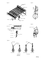
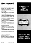
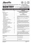
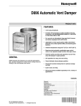
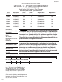
J30-06377
INSTALLATION INSTRUCTIONS
NATURAL to L.P. GAS CONVERSION KIT
For 100,000-400,000 BTU/HR
Spark Ignition Unit Heaters & Duct Furnaces
with Honeywell S8600F Ignition Modules
Input
BTU/H
Conversion
Kit No.
Orifice
Size Nat.
Orifice
Quantity
Original Valve
(See Note)
Replacement
Valve
100,000
125,000
150,000
175,000
200,000
225,000
250,000
300,000
350,000
400,000
261R06377
261R06377
261R06377
261R06377
261R06377
261R06377
261R06377
261R06377
261R06377
261R06377
#54
#54
#54
#54
#54
#54
#54
#54
#54
#54
4
5
6
7
8
9
10
12
14
16
VR8204A2001
VR8204A2001
VR8204A2001
VR8204A2001
VR8204A2001
VR8304M4002
VR8304M4002
VR8304M4002
VR8304M4002
VR8304M4002
N/A
N/A
N/A
N/A
N/A
N/A
N/A
N/A
N/A
N/A
Kit Contents
Main Burner Orifices (16)*
503-00054-016
Pilot Burner Orifice
BBR 11
J36-00785-014
Honeywell Gas Valve Conversion Kit
HW# 393691
J29-04864-001
Honeywell Ignition Module
HW# S8600M1013/3001
J28-02722
Conversion Plate
J17-02755
“Notice of Conversion” Label
J17-02754
This conversion kit shall be installed by a qualified service agency
in accordance with the manufacturer's instructions and all applicable codes
and requirements of the authority having jurisdiction. If the information in these
instructions is not followed exactly, a fire, explosion or production of carbon
monoxide may result causing property damage, personal injury or loss of life.
The qualified service agency performing this work assumes responsibility for the
proper conversion of this appliance with this kit.
AVERTISSEMENT Cette trousse de conversion ne doit être installée que par
le représentant d'un organisme qualifié et conformément aux instructions du
fabricant et à tous les codes et exigences pertinenetes de l'autorité compétente.
Quiconque ne respecte pas à la lettre les instructions du présent guide risque
de provoquer un incendie, une explosion ou des fuites de monoxyde de carbone entraînant des dommages matériels, des lésions corporelles ou la perte
de vies humaines. L'organisme qualifié qui effectue les travaux est responsable
de la conversion correcte de cet appareil à l'aide de cette trousse.
L.P. Gas High Altitude Orifice Chart for The United States
Elevation
(ft.)
Orifice Size
0-1,999
2,000-2,999
3,000-3,999
4,000-4,999
5,000-5,999
6,000-6,999
7,000-7,999
8,000-8,999
9,000-9,999
10,000-10,999
54
54
55
55
55
55
55
56
56
56
L.P. Gas High Altitude Orifice Chart for Canada
Elevation
(ft.)
Orifice Size
0-1,999
2,000-4,500
4,501-5,500
5,501-6,500
6,501-7,500
7,501-8,500
8,501-9,500
9,501-10,500
10,501-11,500
54
55
55
55
55
56
56
56
56
(1 Foot = 0.305 m)
Note: Appliances manufactured prior to
May 1, 2001 may have a VR8304M3103 or
a 36C68-434 gas valve. This kit applies to
the VR8304M3103 valve. Kit No. 261R06378
must be used to convert an appliance with
the 36C68 valve.
*This conversion kit includes (16) main burner
orifices. See the quantity of orifices required per
input/heater size shown in the table above. Use
only the quantity required.
12/06
1. All work must be performed by a fully qualified,
experienced, and trained service technician. It
is the responsibility of the installer to follow all
instructions. Failure to follow these instructions
could result in serious injury or property damage.
2. Remove all burners one at a time by grasping the
front of burner and lifting slightly. Pull the burner
back, compressing the spring, and bring the front
of the burner down to clear the burner bracket.
Be sure to hold onto the air shutters and
springs to keep them from coming off unexpectedly and
causing an injury or getting lost. Slide the burner forward
to clear the main burner orifice.
2. The qualified agency performing the work
assumes responsibility for the conversion.
3. Remove all air shutters and springs. Keep them in
a box or bag until they are needed.
3.
4. Use the proper size wrench or socket to remove
the burner orifices. Remove all the natural gas
orifices and keep them separated from the L.P.
orifices at all times.
READ ALL INSTRUCTIONS COMPLETELY
BEFORE BEGINNING ANY WORK!
The gas supply shall be shut off
prior to disconnecting the electrical power, before
proceeding with the conversion.
**MISE EN GARDE** Avant d'effectuer la
conversion, couper d'abord l'alimentation en gaz,
ensuite, couper l'alimentation électrique.
4. Wear safety glasses.
5. Wear gloves when handling the burners.
6. Be sure of ladder placement. Do not allow people
to stand below or around the area where the work
is being performed.
7. Do not lean ladders or equipment against the
heater at any time during the conversion.
REPLACING THE IGNITION MODULE
The Honeywell S8600F ignition
module must be replaced with the S8600M
module before the heater is operated on L.P.
gas. Tag the wires on the module (if not already
marked) and remove them. Remove the module
and replace it with the S8600M module. Attach
the wires to the new module.
REPLACING THE ORIFICES (SEE FIGURE 1)
1. Natural Vent and Power Vent Unit Heaters and
Bottom Access Duct Furnaces- Remove the
screws holding the bottom burner access panel
and remove the panel.
Side Service Duct Furnaces- Remove lower side
access panel. Tag the wires on gas valve (if not
already marked) and remove them from the valve.
Disconnect gas supply piping from gas valve and
remove piping as necessary so that burner drawer
can be removed. Remove screws securing burner
drawer to heat exchanger and pull burner drawer
out of furnace.
Separated Combustion Unit Heaters and Duct
Furnaces- Remove screws holding bottom burner
access panel and swing panel down.
5. Install L.P. gas orifices in manifold, ensuring
that the number stamped on the orifice matches
the size listed on page one for the appliance
being converted. The orifices must be installed
finger tight first to avoid cross threading and the
possibility of leaking. Tighten securely with
wrench or socket. Do not over tighten.
6. DO NOT INSTALL the burners at this time.
Proceed to “Replacement of Pilot Orifice”.
REPLACEMENT OF PILOT ORIFICE
1. Disconnect the pilot tubing from the gas valve.
2. Natural Vent and Power Vent Unit Heaters and
Bottom Access Duct Furnaces- Remove pilot
access cover on side jacket panel. Remove the
two screws holding the pilot bracket to the side
panel of the burner box. Slide the bracket forward
slightly to disengage the bracket from the side
panel, then rotate the bottom of the bracket out
and up so that the pilot assembly is upside down.
Side Service Duct Furnaces- Remove the two
screws holding the pilot bracket to the burner box.
Slide the pilot bracket forward slightly to disengage
the bracket from the side panel and remove the
pilot and bracket assembly.
Separated Combustion Unit Heaters and Duct
Furnaces- Remove screw holding pilot to bracket
and remove pilot assembly.
3. Remove the pilot gas tubing from the pilot assembly.
4. Using a small screwdriver blade (5⁄32") or similar
tool that will wedge into the orifice, insert the tool
into the tubing fitting of the pilot assembly and
remove the orifice.
5. Insert the L.P. gas orifice into the pilot assembly,
making certain that it does not fall out before the
pilot tubing is installed.
6. Install the pilot tubing finger tight first to avoid
cross threading, then tighten with a wrench.
7. Reinstall the pilot assembly. Reconnect the pilot
gas tubing to the gas valve.
8. Install the first main burner adjacent to the pilot
assembly (see “INSTALLING THE BURNERS”).
Check the dimensional relationship between the
pilot and the main burner (see Figure 2).
These dimensions must be
maintained for safe operation of the appliance.
INSTALLING THE BURNERS
1. Install the spring on the manifold spud.
2. Install one half of the air shutter on the burner.
3. Place the second half of the air shutter on the
manifold spud and compress the spring with this
half.
4. Slide the burner on the spud and keep the spring
compressed with the burner.
5. Position the burner in the corresponding slot
directly across from the spud the burner is on. Lift
the front of the burner up and twist slightly if the
burner does not slide in. Use caution not to distort
the burner.
6. Completely open air shutter, then close two
notches for an initial setting. Each shutter must be
adjusted after the unit is started to avoid yellow
tipping (see “OPERATION”).
7. Replace burner access panel.
CONVERSION OF THE GAS VALVE
1. Follow all instructions provided with the valve
conversion kit. Be sure valve conversion kit is for the
valve on the appliance. If the instructions are lost
or not in the kit STOP. Call the Customer Service
Department and the instructions will be faxed to you.
OPERATION
1. A water filled U-tube manometer must be used to
measure gas pressures. The gauge type is not
reliable and may give false readings.
2. Gas inlet pressure must be 11.0 inches water column
(2.7 kPa) minimum for natural vent and power
vent units and 13.0 inches (3.2 kPa) minimum for
separated combustion units. Maximum gas inlet
pressure is 14 inches (3.5 kPa) for all models.
Turn off the gas supply to the heater, connect the
manometer to the pressure tap on the inlet side
of the gas valve, turn on the gas and observe the
pressure with the heater not firing and then firing. If
the pressure is not within the specified range under
both conditions, contact the gas supplier.
3. The manifold pressure must be adjusted to 10.0
inches water column (2.5 kPa) for natural vent and
power vent units and 10.5 inches (2.6 kPa) for
separated combustion units. This manifold pressure
applied to #54 main burner orifices assures that the
input rating is correct for altitudes up to 2000 feet
(610 m). For altitudes above 2000 feet (610 m),
see (4) below. This is very critical as overfiring or
underfiring can cause problems. Move the manual
control on the gas valve to the “Off” position, connect
the manometer to the pressure tap on the outlet
side of the gas valve, turn the control on, fire the
unit and adjust the pressure if necessary. To adjust
the pressure, remove the cap from the pressure
regulator on the gas valve, turn the regulator screw
clockwise to increase pressure or counter clockwise
to decrease pressure, then replace the cap.
4. For altitudes above 2,000 feet (610 m), heater must
be derated 4% for each 1,000 feet (305 m) above
sea level. See Orifice Chart for correct orifice size for
high altitude operation. High altitude orifices are not
included in kit and must be ordered separately.
5. After manometers have been removed and pressure
tap plugs have been reinstalled, fire the heater and
check all joints for leaks using a soap solution. Never
use an open flame to check for gas leaks.
6. The pilot flame should be 3/4 to 11/2 inch (19 to
38 mm) in length (see Figure 3). To adjust the pilot
flame, remove the pilot adjustment cover screw
adjacent to the pilot tubing nut on the gas valve.
Turn the inner screw clockwise to decrease pilot
flame or counterclockwise to increase pilot flame.
Replace the cover screw.
7. Allow the heater to operate for at least 5 minutes,
then observe main burner flames. A hard blue
flame with no lifting and no yellow tipping is
normal. See Figure 4. If air shutter adjustment
is necessary, close air shutter gradually until
yellow tipping appears, then open just enough to
eliminate the yellow tipping. Wear gloves when
handling the air shutters.
8. After the heater is operating properly, cycle the
system using the thermostat to check out the normal
operating sequence of the ignition system. The
normal sequence is as follows: Thermostat calls
for heat, opening pilot section of gas valve and
energizing spark at pilot. Pilot flame ignites. Sensing
circuit senses pilot flame, turns spark off, and allows
main valve to open. Pilot ignites gas on first main
burner. Flame travels along first burner to carryover
slots, then travels back along each remaining main
burner. When thermostat is satisfied, both sections
of the gas valve are de-energized, extinguishing all
main burner and pilot flames.
9. Apply conversion plate and label to heater jacket
panel. The conversion plate must be installed as
closely as possible to the existing heater rating plate.
Figure 1
Figure 2
FRONT BURNER
BRACKET
1/16
CARRY-OVER
1/4
MAIN BURNER
PILOT BURNER
MANIFOLD
PILOT TUBING
Figure 3
MAIN BURNER
BURNER SPRING
3/4 to 1-1/2 inch
MANIFOLD
AIR SHUTTER
MAIN BURNER
ORIFICE
PILOT BURNER
SPARK LEAD
PILOT ORIFICE
TUBING FITTING
Figure 4
Blue Flame
Yellow
Distinct
Inner Cone
Normal Flame
Lifting
Too Much Air
or Excessive
Gas Pressure
Yellow Tipping
Yellow Flame
Too Little Air
D06386