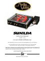
1
SUNILDA Instruction Manual model – 2013 ultra highend RIAA MC and MM phono amp We congratulate you with the purchase of this superb AUDIOVALVE - HiFi component. This handcrafted product has been manufactured with only your most demanding requirements in mind. It was made to allow you many years of musical joy. AUDIOVALVE guarantees that this amplifier has been produced under the strictest of guidelines and with respect for procedures acquired through decades of tube amplifier design. Your SUNILDA Preamplifier has been thoroughly tried and tested in all detail. I personally guarantee the quality of this product Helmut Becker, Design & Production SUNILDA ultra highend phono tube amplifier____________________________ Table of contents - Introduction and general information - Manufacturers information - Safety precautions - Intended use / Application / Factory assembly & getting started - Operating instructions & technical features - Set - up and installation - Warranty Introduction Dear client, we congratulate you on your purchase of this superb AUDIOVALVE HiFi component. To safeguard maximum functionality and to avoid operating problems, it is important that you carefully study this owners manual and that you follow all instructions therein precisely! General information Important instructions, regarding safety, securety and operational reliability while using the SUNILDA Pre-Amplifier are highlighted throughout this manual. Factory address: AUDIOVALVE, H. Becker, Umbachsweg 70 D-34 123 KASSEL GERMANY, Tel.: 0049 - (0) 561 7013360 Fax: 0049 - (0) 561 6029293 Email: [email protected] website: www.audiovalve.info SUNILDA ultra highend phono tube amplifier____________________________ Safety precautions Important: Study the owners manual before assembly and operation of the amplifier Anyone, unable to comprehend the instructions stated in the owners manual should not operate the device. Children and minors are not to use the device and should be kept at a safe distance from the device while it is running. The user is responsible for operating the device in an appropriate fashion and it takes full responsibility towards third parties. Before the amplifier can be used the first time, suitability of taken precautions regarding electrical safety must be approved through professional assessment. Check that the mains voltage printed on the rear panel of the amplifier corresponds with the line voltage in the territory where you intend to use the amplifier. Always check powercords and plugs for damage before use. Disconnect the powercord before work is being done on the amplifier. In the unlikely case of a failure of the device repairs may be performed by AUDIOVALVE authorized technicians only. Use ORIGINAL spare parts only! Please take note of the fact that we waive product liability for damages caused bij our devices, parts and components as a result of: a) Unprofessional and / or faulty and / or correct repairs that have been performed in other than the by AUDIOVALVE approved repair facilities, b) Usage of other than ORIGINAL and approved spare parts. The SUNILDA Pre-Amplifier is subject to and complies with German security class 1 for devices with metal housing. The device is grounded, and may not – by manipulation or otherwise be ungrounded for any reason! To prevent hum as a result of interconnecting your devices with the SUNILDA Pre-Amplifier, the internal electrical circuitry has been designed to have no grounded mass!! SUNILDA ultra highend phono tube amplifier____________________________ SUNILDA ultra highend phono tube amplifier____________________________ Product Description Sunilda is a three stage phono-preamplifier, based on 6922 (ECC88) and 12AX7 (ECC83) frame grid tubes, suitable for MM- and MC-cartridges. Independently for the two phono inputs, impedance and capacitive load can be set separately and 'on-the -fly' while listening. Thus the user can easily configure the unit to match the features of the cartridge by selecting the optimal input resistance and capacitance for each input separately! Sunilda comes in an laser cuted 3 mm thick steel, chassis in black or silver finish and has a case similar to the Eklipse line amplifier. SUNILDA ultra highend phono tube amplifier____________________________ Switches are found for: MM/MC mode for each input; input 1 or 2; selectors are used to select different R and C loads. Two selector knobs for each input capacitive and resistor load Frontpanel from SUNILDA In MM mode the gain will be 20 dB lower than MC and at a fixed input- impedance of 47K. In MC mode the preamp will have higher gain and switchable input resistors and condensers. The RIAA de-emphasis is passive and split between the first and second stage. Dividing the RIAA network over two amplification stages lowers the insertion losses of the passive network dramatically. Furthermore, the design holds a total absence of feedback, thus increasing the overall dynamics. Rearside panel from SUNILDA The power supplies are solid state regulated. This is the best way to obtain a low noise and supply line with a very low impedance that will increase the performance in the lower frequency range. The power transformer is housed in a separate aluminum case. The pic show you the real side panel with connector for the power supply ( blue left one ) and the turntable earth grounding terminals ( black posts ), 2 RCA cinch output jackets and 2*2 input RCA jackets. SUNILDA ultra highend phono tube amplifier____________________________ separate power case supply case with the MAIN switch, MAIN plug with integrated fuse holder and the CENTRONICS multi wire connector for the amp. Intended use / Application AUDIOVALVE Hi-Fi Amplifiers are intended for use under the following circumstances only: To play and transfer music of any make and fashion when this occurs in private dwellings or studios. All devices must be operated under moderate climatological circumstances, comparable to those underwhich human beings usually live. When the surrounding temperature is too high, the device will heat up beyond its optimal parameters. This can damage the amplifier. Proper ventilation will be needed, and the amplifier should not be covered in. Allow approximately 3 cm of air sidewise and approximately 4 cm above the amplifier to cool the amplifier. Unusually high humidity of the air increases the risk of shortcircuits in the device because of the increased conductivity. This reduces the internal insulation values dramatically and will eventually result in a malfunction of the amplifier. This increased conductivity also might endanger the user of the device. In general terms the amplifier should not be used for other than its intended purpose. SUNILDA ultra highend phono tube amplifier____________________________ Factory assembly & getting started Once the amplifier has arrived at its desired destination, make sure the amplifier has ample time to adjust to the climate at its new location. It is likely that the changes in temperature and humidity between the last location and the new one, has caused condensation to build up somewhere in the amplifier. This can damage the device. Please allow the amplifier at least two hours to acclimatise. The amplifier comes fully assembled, ready to go. The powercord should not be used as yet, please connect all other input and output connectors first (cinchcables, speakercables, etc). The device MUST be switched off while connecting it to other components, it might be damaged if this is done with the amplifier under power. The person operating the amplifier might be hurt as well in this case, since powerspikes, operating currents and voltage charges may occur! Check whether the ON/OFF switch is in the OFF position. If so, you can now plug in the powercord. Use high quality cables only! Usage of DIY cables, low spec cables or cables intended for other use voids all warranty and cancels any product liability. Make sure all plugs are connected tightly to the amplifier. When in doubt, replace the cable. Always use the device in a ’complete configuration’ , damages may occur when devices are not connected to the amplifier when it is being run. Never lift the device by its glass cover, not even when there are gripps attached to the cover. The gripps and the cover are there for ornamental purposes only. They make the amplifier look nice. The amplifier should be positioned at a level surface, in time the construction of the glass housing may fail as a result of tensile forces. Please disconnect and move the amplifier when you replace tubes. Replace them at a place where you can work easily. You might damage the ’motherboard’ if you replace the tube in an awkward position. After that please check all connectors. If all connectors are undamaged, make sure the switch is in the OFF position, reconnect the powercord and swith the amplifier on. You can make sure the amplifier is properly connected by checking the tubes. Only the inside of the tube should glow. If the steel coverjacket glows as well, the device is faulty and must be serviced immediately. As a rule of thumb the device should work now. Don’t push the volume up to its maximum just yet, allow the device to burn in smoothly and avoid powerspikes. The SUNILDA Pre-Amplifier needs at least a 1.6 Ampere slow blow circuit breaker in the fuse holder for 230 VAC main voltage and 3,15 ampere slow blow by 115 VAC. Make sure your wall socket is equiped in such a fashion. SUNILDA ultra highend phono tube amplifier____________________________ Controls and operation on the front and rear panel The frontside of the SUNILDA has a number of controls, whose function should be elaborated upon. When switched ON, the amplifier is always in MUTE during the first minute - nealy one minute. The amp is also in MUITE - function for a wile, when you handle one of its 4 little rocker switches on the freont panel, you see the yellow LED shinning. This prevents power spikes that may be caused by the voltage spikes what will be produced, when you handle the little rocker switches to reach the outputs. When the safe MUTE period is over the amplifier is ready for use and spend the signal to the OURPUT terminals. Never change a fuse when the amplifier is connected to the mains or when you are unsure about the proper functioning of the device. Never replace a blown fuse with a other values than printed on the unit! Whenever you perform any service or modification to the SUNILDA Pre-Amplifier, make sure the device has been disconnected from the mains and leave the work to a professional only! The design of the circuit board allows you a view upon the most important element that might be subject to service or modification. When you decide to replace pin-compatible tubes, always switch the SUNILDA amplifier o OFF before doing so. And make sure all pins actually enter the sleeve of the receptor. Pins have a tendency to wander outside their assigned realms... The SUNILDA Concept The SUNILDA boasts a huge amount of innovative solutions that are hard to find in tube - amplifiers in this price range. To balance currents in the tubes and to make sure they operate at peak efficiency within their tolerances, semiconductors are used. The SUNILDA has been designed to be a real double mono amplifier, which means both channels have their own power supply. A design characteristic that is no standard option with even much more costly devices. When you switch the volume off, the SUNILDA is SILENT. Please note both the minimal background noise and the equaly low input noise level the SUNILDA Pre - Amplifier scored in tests. That is no mean feat. Like all AUDIOVALVE amplifiers, the SUNILDA has been designed to be a timeless piece, a high closs powder coated 3mm thick laser cut steel with gilded connectors. That concludes the basic technical description of the amplifier, continue reading for the really important stuff. IIMPORTANT: In the 4th quarterly issue 2005 of the HI-FI magazine “xxxxx“ the SUNILDA have been tested and reviewed exhaustingly. These tests will probably answer any questions regarding musical performance and technical specs you might have. SUNILDA ultra highend phono tube amplifier____________________________ Technical Specifications: MM mode gain: MC mode gain: MM / MC mode input impedance: Frequency Response: Subsonic filter roll-off: Max output amplitude: Max input amplitude: RIAA accuracy: Distortion: Noise: Circuit type: RIAA network Resistors: Capacitors: Tubes: more mode functions: Power supplies: transformer: requirements: consumption: Watts: Dimensions: cm, W x H x D : Weight: Kg: dB - 1Khz dB - 1Khz resistors: 1> 47R, 2> 100R, 3> 220R, 4-> 470R, 5> 1K, 6> 47 K capacitors: 1> 0p, 2> 100p, 3> 220p, 4> 470p, 5> 1n, 6> 0p 20Hz to 65 KHz +/- 3 dB 20 Hz 14V pk 200 mV +/- 0,25dB 0,24 % (1Khz - 10Vpk out) 76 dB below signal (MC mode) 3 stages single ended, buffered ouputs passive - split between 1st and 2nd stage 1 % metal film MKP - styroflex - fast electrolytic 2 x 6922 input, 2 x 12ax7 output Stand - by and mute Solid state regulated outside in a separate case 115/230 - 245 Ac - 50/60Hz 60 VA 42 * 32 * 14 ( same as Eklipse ) 20 kg SUNILDA ultra highend phono tube amplifier____________________________ Set-up and installation of the Phono Amplifier SUNILDA After having unpacked your phono equipment set the phono pre- amplifier up at its chosen place. The power supply should be positioned at a distance from the pre-amplifier by at least the length of the connecting cable. Equally, other large electrical consumers should not be positioned near SUNILDA and the record player. The power supply can be best placed on the floor, however make sure the power switch on the front of the power supply is visible and within reach. Only when manipulating this main switch on the power supply SUNILDA is either made alive or, after having switched off, is completely dead – identification by means of a red LED at the right front of the power supply. The LED shines, if the pre-amplifier is switched OFF at the switch on the front of the amplifier, with the power supply, however remaining alive. The red LED signals that the power supply is still alive. In case the amplifier will not be used for a longer period of time, as f.Ex. in holiday times, make sure the amplifiers power supply case as well is cut OFF !!!! After having set-up both appliances at first connect power supply and amplifier with the included CENTRONICS cable and secure the cable against falling out at both ends. Subsequently connect the power supply to mains voltage by means of the power cord. Ensure that the power supply is switched OFF with no LED shining at the appliance. Now start to install the signal lines between the pick—up and SUNILDA. Fix the earth conductor of the record player to the earth terminal assigned to each input at the back of the pre- amplifier next to the cinch inputs. Cable the output of the SUNILDA phono pre-amplifier to your EKLIPSE pre-amplifier using the appropriate cinch cables. The pre-amplifier is still cut OFF. When putting the power supply into operation, the red LED at the right front of the amplifier below the ON – OFF switch begins to shine. Before you also connect the pre-amplifier, check the settings for the pick-up at the appliance . SUNILDA ultra highend phono tube amplifier____________________________ If connecting only one system, please use the input 1 according to the marking at the back of the appliance. Make sure the cinch cables as well as the adjacent earth conductor are well fitted. At the right of the front screen you will find a row of flip switches ( little rocker switches ). Only the switch in the middle – to be actuated at level – indicates the input to be used by yourself. Flip this switch to the left, if you have configured to input 1 at the back. Flip it to the right, if you have also configured to input 2 and intend to use both inputs. There is an additional switch each at the right and at the left of the level flip switch – to be actuated vertically – assigning the connected pick-up by model to the respective input. The flip switch is flipped upwards, if a MC system is connected to the respective input and is flipped downwards when connecting a MM system. The very left switch of all 4 flip switches can M U T E the output signal, if being flipped upwards (yellow LED) or can change into STAND - BY mode (red LED) with the switch pointing downwards. In this case SUNILDA is heated up without anode supply voltage. With the switch in neutral position none of these two functions are active. This switch position is neutral and usually the prefered position. Relevant information: Whenever one of these 4 flip switches is actuated, the outputs of the phone pre-amplifier are muted – for a period of 15 secs. – to suppress the internal voltage variations at the output. This is for safety control only. When you worried about your speakers, please adjust the pre amplifers volume potentiometer downwards, so that no signal spikes can be reach your power amplifier and speakers. IMPEDANCE By means of the four rotary knobs at the left side of the front screen the impedances for the pick-up's are selected for both outputs independantly from each other. Looked at from the middle the knobs are in a mirror-inverted position, i.e. the two middle rotary knobs select the load resistance for the pick-ups: the middle left knob for input 1 and the middle right knob for input 2. By means of the outer rotary knobs the appropriate leading load for the individual input is selected. You may change these settings at the amplifier, if required. SUNILDA ultra highend phono tube amplifier____________________________ The two middle rotary knobs select low impedances for MC systems in the first five switch positions starting from the left. The last position at the very right of these switches has a 47kOhm load and is intended for use with MM systems. So for MC systems chose the impedances 47 R up to 1 k in the first five switch positions and select the impedance in the sixth switch position (MM – 47k), if a MM system has been connected to this input. According to your requests all switch positions may be combined in any order thus allowing the simulation of a large number of different loads for your pick-ups. Note: Always turn down the volume at the pre-amplifier to safeguard your speakers when changing the following settings at SUNILDA: 1) 2) When switching over from one input to another input. When switching from MM to MC, because the amplification increases by 20dB. A view of the compact and absolute wireless electronic - riaa modul from SUNILDA. There is no hum, bee or any noise - only music. The design on a double side pc board is constructed in double mono technology, use best and selected components and guarantee high stable and highend vinyl re productions. SUNILDA ultra highend phono tube amplifier____________________________ WARRANTY AUDIOVALVE warrants its components for a three-year period on all electronics and a 90-day period on the tubes from the purchase date. In the event of a failure of your amplifier, AUDIOVALVE will repair or readjust this unit or, should the occasion arise, will replace it provided that all conditions stipulated in this warranty are met. In order to initiate service of any kind it is necessary to obtain distributor or dealer authorization prior to shipping the unit for service. Any of the following conditions shall void the warranty: Operation not in accordance with this manual. Abuse , accidental damage or unauthorized modifications , as determined by AUDIOVALVE or its agents exclusively. Removal, defacing or falsifying of the serial numbers. Shipping without the original complete factory crates. WARRANTY REGISTRATION Please fill out and return this warranty form to the distributor within 15 days of the purchase date, or fill out our online warranty registration form at: www.a udova lve.info MODEL : SERIAL NUMBER : PURCHASE DATE : AUTHORIZED AUDIO - VALVE DEALER: PURCHASER`S NAME : STREET ADDRESS : CITY : ZIP / POSTAL CODE : SUNILDA ultra highend phono tube amplifier____________________________ CE – Confirmity Declaration Of Conformity Manufacturer: AudioValve, Germany, 34123 KASSEL, Umbachsweg 70, [email protected] Product Name: SUNILDA Product Type: Audio Amplifier Complies with Standards: LVD: 92/31/EEC, 93/68/EEC, & 73/23/EWG Safety: EN60065 EMC: EN55013, EN55020, EN55022, EN55103, EN61000-3-2, & EN61000-3-3 The official Declaration of Conformity for this product is kept on file at: AudioValve, 34123 Kassel,Umbachsweg 70, Tel. 05617013360