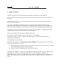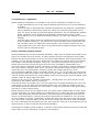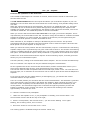
1
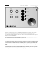
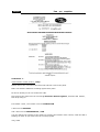
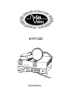
Owners Manual
EKLIPSE
Line – pre - amplifier
We congratulate you with the purchase of this superb AUDIO VALVE HiFi component.
This handcrafted product has been manufactured with only your most demanding requirements in
mind. It was made to allow you many years of musical joy.
AUDIO VALVE guarantees that this amplifier has been produced under the strictest of guidelines
and with respect for procedures acquired through decades of tube amplifier design. Your Eklipse
Pre-amplifier has been thoroughly tried and tested in all detail.
Eklipse
line
pre
amplifier
Table of contents
1.
2.
3.
4.
5.
6.
Introduction and general information
Manufacturers information
Safety precautions
Intended use / Application / Factory assembly & getting started
Operating instructions & technological data
Warranty
_____________________________________
1.Introduction
Dear client, we congratulate you on your purchase of this superb AUDIO VALVE HiFi component.
To safeguard maximum functionality and to avoid operating problems, it is important
that you carefully study this owners manual and that you follow all instructions therein
precisely!
General information
Important instructions, reagrding safety, securety and operational reliability while using the Eklipse
Pre-Amplifier are highlighted throughout this manual.
2. Herstellernachweis
Factory address:
AUDIOVALVE, Mr. Helmut Becker,
Umbachsweg 70
D-34123 KASSEL - GERMANY,
0561 - 701 33 60
0160 910 77 376
0561 – 60 2929 3
[email protected]
www.audiovalve.info
U-St.Ident.Nr.: DE 195 191 420
WEEE-Reg.Nr.: DE81178274
Eklipse
line
pre
amplifier
3. Safety precautions
Important: Study the owners manual before assembly and operation of the amplifier
Anyone, unable to comprehend the instructions stated in the owners manual should not operate
the device.
Children and minors are not to use the device and should be kept at a safe distance from the
device while it is running.
The user is responsible for operating the device in an appropriate fashion and it takes full
responsibility towards third parties. Before the amplifier can be used the first time, suitability of
taken precautions regarding electrical safety must be approved through professional assessment
Check that the mains voltage printed on the rear panel of the amplifier corresponds with the line
voltage in the territory where you intend to use the amplifier.
Always check powercords and plugs for damage before use.
Disconnect the powercord before work is being done on the amplifier.
In the unlikely case of a failure of the device repairs may be performed by AUDIO VALVE
authorized technicians only.
Use ORIGINAL spare parts only!
Please take note of the fact that we waive product liability for damages caused bij our devices,
parts and components as a result of:
a) Unprofessional and/or faulty and/or correct repairs that have been performed in other than
the by AUDIO VALVE approved repair facilities,
b) Usage of other than ORIGINAL and approved spare parts.
The Eklipse Pre-Amplifier is subject to and complies with German security class 1 for devices with
metal housing. The device is grounded, and may not –by manipulation or otherwise- be
ungrounded for any reason! To prevent humm as a result of interconnecting your devices with the
Eklipse Pre-Amplifier, the internal electrical circuitry has been designed to have no grounded
mass!!
Eklipse
line
pre
amplifier
4. Intended use / Application
AUDIO VALVE Hi-Fi Amplifiers are intended for use under the following circumstances only:
To play and transfer music of any make and fashion when this occurs in private dwellings
or studios.
All devices must be operated under moderate climatological circumstances, comparable to
those underwhich human beings usually live. When the surrounding temperature is too
high, the device will heat up beyond its optimal parameters. This can damage the amplifier.
Proper ventilation will be needed, and the amplifier should not be covered in. Allow
approximately 3 cm of air sidewise and approximately 4 cm above the amplifier to cool the
amplifier.
Unusually high humidity of the air increases the risk of shortcircuits in the device because
of the increased conductivity. This reduces the internal insulation values dramatically and
will eventually result in a malfunction of the amplifier. This increased conductivity also
might endanger the user of the device. In general terms the amplifier should not be used
for other than its intended purpose.
Factory assembly & getting started
Once the amplifier has arived at its desired destination, make sure the amplifier has ample time to
ajust to the climate at its new location. It is likely that the changes in temperature and humidity
between the last location and the new one, has caused condensation to build up somewhere in the
amplifier. This can damage the device. Please allow the amplifier at least two hours to acclimatise.
The amplifier commes fully assembled, ready to go. The powercord should not be used as yet,
please connect all other input and output connectors first (cinchcables, speakercables, etc).
The decive MUST be switched off while connecting it to other components, it might be damaged if
this is done with the amplifier under power. The person operating the amplifier might be hurt as
well in this case, since powerspikes, operating currents and voltage charges may occur!
Check whether the ON/OFF switch is in the OFF position. If so, you can now plug in the powercord.
Use high quality cables only! Usage of DIY cables, low spec cables or cables intended for other use
voids all warranty and cancels any product liability. Make sure all plugs are connected tightly to the
amplifier. When in doubt, replace the cable.
Allways use the device in a ’complete configuration’ , damages may occur when devices are not
connected to the amplifier when it is being run.
Never lift the device by its glass cover, not even when there are gripps attached to the cover. The
gripps and the cover are there for ornamental purposes only. They make the amplifier look nice.
The amplifier should be positioned at a level surface, in time the construction of the glass housing
may fail as a result of tensile forces.
Please disconnect and move the amplifier when you replace tubes. Replace them at a place where
you can work easily. You might damage the ’motherboard’ if you replace the tube in an awkward
position. After that please check all connectors. If all connectors are undamaged, make sure the
switch is in the OFF position, reconnect the powercord and swith the amplifier on. You can make
sure the amplifier is properly connected by checking the tubes. Only the inside of the tube should
glow. If the steel coverjacket glows as well, the device is faulty and must be serviced immediately.
As a rule of thumb the device should work now. Don’t push the volume up to its maximum just yet,
allow the device to burn in smoothly and avoid powerspikes.
The Eklipse Pre-Amplifier needs at least a 10 Ampere circuit breaker between its powercord and the
mains. Make sure your wallsocket is equiped in such a fashion.
Eklipse
line
pre
amplifier
Controls and operation on the front side
The frontside of the Eklipse has a number of controls, whose function should be elaborated upon.
We start from the left:
The left selectorswitch balances the outputs and allows you to MUTE the amplifier or put it on
STAND BY. The five LEDs under the knob indicate the chosen setting, each possible setting has its
own LED.
When the outermost left LED is lit permanently, the device is in STAND BY mode, e.g. the tubes
are heated up but no anodecurrent is passed through them. Simultaniously the outputs of the
amplifier are muted, which is represented by the lighting of the orange LED for MUTE, next to the
red LED for STAND BY. The STAND BY position is remote controllable.
When you turn the left selectorswitch ONE POSITION to the right, you mute the amplifier. This is
represented by the second LED from the left. The LED is orange and it blinks to underline the MUTE
position the amplifier is in. When muted, the outputs are shorted to prevent signal leaving the
amplifier. The MUTE position is remote controllable as well.
When switched on, the amplifier is allways in MUTE during the first minute. This prevents
powerspikes that may be caused by the large magnetic coils to reach the outputs. When the safe
MUTE period is over the amplifier is ready for use.
When you select the centre position with the selectorswitch, output 1 is selected as the functioning
amplifier output, this is represented by the green centre LED of the five. The slection of functioning
outputs is available through the selectorswitch only, the remote control doesn’t allow you to select
this option. The balanced XLR output is always switched on, regardless of the slected cinch output.
Position four of the selectorswitch selects output 2 as the functioning output, a second green LED
shows you you’ve selected this option.
The fifth (and last) setting of the selectorswitch allows outputs 1 and 2 to function simultaneously.
Just as a reminder: The outputs can only be selected through the selectorswitch.
On the righthand side of the outermost left selectorswitch, another selectorswitch allows you to
select seven different input devices, each represented by seven green LEDs.
The first LED from the LED corresponds with the most left input, which is CD1. The next LED is for
the next input, etc. A maximum of seven devices can be used as input devices with the Eklipse PreAmplifier.
If you turn the knob into the eighth position (no LED lighting up), you activate the remote
controled selection of input devices.
There is a nineth position you can select with the second selectorswitch. This activates a generator
which mechanically cleans all relais in the Eklipse Pre-Amplifier. When selecting ths option, turn
down the volume completely first and disconnect your power amplifier before switching to the
nineth position. The mechanical usage of the connectors through the generator prevents the
buildup of oxidation on the contacts. We advise you perform this cleansing of the contacts
approximately 10 minutes per week.
To clean the contacts in the preamplifier.
1. Make sure the amplifier is off , 2. put preamplifier in standby, turn selector switch – the
second switch from the left all the way to the right ,
2. which is ninth position, with volume at zero , you will see the flashing L.E.D lights
flashing ,and a clicking sound , this is normal .
3. Proceed to do this for ten minutes once a week.
The cleaning option is available through the selector switch only.
Eklipse
line
pre
amplifier
Both remaining switches on the righthand side serve volume control and ballance adjustments.
Volume can be changed through both the controlswitch and the remote control. Underneath the
volume control a red LED aknowledges the receipt of signal from the remote conrol. Secondairy to
this function, the LED is a control mechanism for the proper functioning of the remote control.
The balance is meant as fine-tuning between both stereo channels only, the maximum adjustment
lies around +/- 3 dB. It is not meant to serve as a means to switch one of the channels off
completely. The fine-tuning of channels can not be performed with the remote control.
Fu n k t io n
a
b
c
d
So u rc e
e
1
2
3
4
5
Vo lu m e
6
7
8
9
Ba la n c e
Po w e r
pre tube ampilifier
At the uttermoist righthand side of the front pannel, you find the ON/OFF switch which allows
power into the unit or shuts it down. When you touch the white indicator on the switch, the device
is switched on. A blue LED under the ON/OFF switch indicates whether the device is switched on or
not. A shining blue LED means the amplifier is witched on.
Also under the ON/OFF switch you’ll find the receptor for the infrared remote control unit. Keep this
receptor free to receive signals at all times. There is virtually no limit to the angles underwhich the
amplifier will be able to receive a signal from the remote control. The amplifier can only be
switched on and off through the switch on the front of the amplifier.
Zusammengefasst noch mal die Funktionen der manuellen und fernbedienbaren Möglichkeiten.
A short overvieuw of the options, both manually and with the remote control
-
STAND BY – manually and remote control
MUTE – manually and über RC
Output 1) Cinch) – manually
OUTPUT 2 (Cinch) – manually
Beide Output – manually
XLR always functional
Input devices manually and RC (manuall prevails)
Relais cleaning mode – manually
Volume – manually und RC
Balance – manually
ON/OFF manually (ON/OFF switch)
Eklipse
line
pre
amplifier
2
XLR
2
3
XLR
1
Left
1
Rigth
Mainplug
Eklipse preamplifer
Fuse
Desciption of the rear panel
The following description deals with the rear panel of the Eklipse Pre-Amplifier, seen from behind.
The black socket on the lower lefthand side is AC mains input, conforming to Euro mains input
specifications. The overload fuse is integrated into the same socket.
When the amplifier runs on 117 Volts, a 2 Ampere fuse must be used. When it runs on 235 Volts, a
1 Ampere fuse must be used.
Never change a fuse when the amplifier is connected to the mains or when you are unsure about
the proper functioning of the device. Never replace a blown fuse with a other values than printed
on the unit!
Above the AC socket you find two balanced XLR amplifier outputs, that are always active. You can
use these outputs when you find them suiting your requiremens better than RCA/Cinch outputs.
The XLR outputs only relay the positive sourcesignal, the negative source (or negative contact) of
these XLR outputs is connected to the amplifiers mass. This type of XLR is also known as “FAGE“
output.
Netx to the XLR outputs you’ll find the Cinch/RCA outputs that provide the output signal of this PreAmplifier. The contents of the signal being relayed ca be determined by the outermost righthand
selector switch on the front panel of the Eklipse Pre-Amplifier.
Next to both outputs you find the “REC OUTPUT“ connector, which relays the signal transmitted
inside the amplifier, without amplifying it. This signal is just the signal that entered one of the
inputs and can be used for further processing in e.g. a tape unit or a digital mastering device.
The remainder of cinch connectors has been assigned to the source devices, as indicated with the
selector switch on the front panel.
The technical specifications of the inputs are describted in detail in the technical data supplement.
Eklipse
line
EC C 8 2
EC C 8 0 2 S
61 89
pre
amplifier
In c o rre c t p h a se - p le a se c h a n g e
M a in v o lta g e
61 89
Fu se 0 .5 sb
(Pla te )
Fu se 3 .6 sb
(H e a tin g )
EC C 8 2
EC C 8 0 2 S
61 89
61 89
Fu se 0 .5 sb
Fu se 3 .6 sb
1 6 0 VA p o w e r Tra n sfo rm e r
Whenever you perform any service or modification to the Eklipse Pre-Amplifier, make sure the
device has been disconnected from the mains and leave the work to a professional only!
The design of the circuit board allows you a view upon the most important element that might be
subject to service or modification.
The circuit board provides you with a blueprint of the amplifiers design and gives you full view of
the components that may be most interesting to you, the user.
The four tubes are identical, and are part of the ECC 82 family. This renders the amplifier relatively
overloadproof. The two lefthand side tubes provide the input to one channel, the righthand tubes
take care of the other channel. The amplifier transmits phased amplified signals, which means you
do not have to bother about your speakers’ polarity as long as you stick to the colourcoding of your
cables.
Paramount for the sound quality are both lefthand tubes (the entrytubes), since they amplify the
signal being put into them. Please don’t economise on these tubes. The righthand tubes (the
exittubes) are much less demanding when it comes to quality.
Eklipse
line
pre
amplifier
When you think the AC current entering your amplifier is out of phase with the amplifier, you might
considder switching both wires under the tripolar connector on the upper righthand side. Thus you
reverse the AC flow, and therewith the polarity. Never do this when the amplifier is still connected
to the mains. Please considder having having this modification done by a professional electrician.
Another worthwhile subject is the 4 fuses that are part of the double mono channels. The 0.5
Ampere fuse deals with the anode current, the 3.15 Ampere fuse warrents against overheating of
the respective channels. As a rule of thumb, these fuses never blow since the current is
automaticaly modulated to acceptable levels at startup.
Should a fuse blow regardless, never change it for a fuse with different specifications!
Fuses blow for a reason. Eventhough AUDIO VALVE equipment is made to last untill the end of
time, sometimes things do break. Ask for our help when this happens.
When you decide to replace pin-compatible tubes, always switch the Eklipse amplifier off before
doing so. And make sure all pinns actually enter the sleeve of the receptor. Pins have a tendency
to wander outside their assigned realms...
The Remote Control
The remote control is easy to use, just press the button corresponding with desired functionality.
About once a year the two 1.5 Volts batteries must be changed. To change the batteries open the
batery cover on the back of the RC. Change the bateries and close the cover. Make sure the
batteries are placed in the right polarity.
When you have questions regarding the change of batteries, please consult your vendor or give us
a call.
The M2R and IR2R function identically, except for the absence of a remote control with the M2R.
The RC functions are taken care of by brass selectors on the M2R.
Eklipse
line
pre
amplifier
The Eklipse Concept
The Eklipse boasts a huge amount of inovative solutions that are hard to find in tube-amplifiers in
this pricerange. Ofcourse, the Eklipse is a pure-tube amplifier, the signal meets nothing but tubes
on its way out.
To balance currents in the tubes and to make sure they operate at peak efficiency within their
tollerances, semiconductors are used. The Eklipse has been designed to be a pure double mono
amplifier, which means both channels have their own power supply. A design characterisric that is
no standard option with even much more costly devices. The technicians among you may be
pleased to know that the amplifier section is difference amplifier built, meaning that the output
signal is phase-opposed to the input signal. The balance potentiometer has been integrated into
the input of the pre-amplifier. The volume control is a technical beauty as well. Naturally, the
volume is controlled through an ALPS potententiometer. Contrary to common design, the volume
control has not been integrated in the the amplifiers input bur in the final kathode-stage of the
amplification proces.
When you switch the volume off, the Eklipse is SILENT. Please note both the minimal background
noise and the equaly low input noise level the Eklipse Pre-Amplifier scored in tests
That is no mean feat. Like all AUDIO VALVE amplifiers, the Eklipse has been designed to be a
timeless piece, a high closs powder coated 4mm thick lasercut steel with gilded connectors. That
concludes the basic technical description of the amplifier, continue reading for the really important
stuff.
IIMPORTANT: In the 4th quarterly issue 2000 of the american HI-FI magazine “ULTIMATE AUDIO“
the EKLIPSE and the CHALLENGER have been tested and reviewed exhaustingly. These tests will
probably answer any questions regarding musical performance and technical specs you might have.
Technical Data:
Specification
EKLIPSE
Concept:
Output Level:
Power Bandwide:
Distortion:
Noise:
Inputs:
7 Line
Outputs:
fage XLR, two
Output Impedance:
Power Consumption:
Line Voltage:
Valve Line - Up:
Spec.-Features:
Dimensions:
Weight Net:
high class double mono pre-amplifier
15 V max.
4 - 45.000 Hz
0,2 % max. (1V)
0,05 mV (volume noise limiter) (-110 dB)
In, & 1 Line Out
switch able RCA terminals, one REC. out – all in phase
200 Ohms
40 Watt
117 up to 260 VAC
4*6189 (or equivalent)
Stand By & Mute Function, remote – Control, relays cleaner
160 Watt power transformer, “switch one” current limiter
(w-d-h)420 * 320 * 130 mm
20 kg
Eklipse
line
pre
amplifier
WARRANTY
AUDIO VALVE warrants its components for a three-year period on all electronics and a 90-day
period on the tubes from the purchase date.
In the event of a failure of your amplifier, AUDIO VALVE will repair or readjust this unit or, should
the occasion arise, will replace it provided that all conditions stipulated in this warranty are met.
In order to initiate service of any kind it is necessary to obtain distributor or dealer authorization
prior to shipping the unit for service.
Any of the following conditions shall void the warranty:
•
Operation not in accordance with this manual.
•
Abuse , accidental damage or unauthorized modifications , as determined by AUDIO VALVE or
its agents exclusively.
•
Removal, defacing or falsifying of the serial numbers.
•
Shipping without the original complete factory crates.
WARRANTY REGISTRATION
Please fill out and return this warranty form to the US distributor within 15 days of the
purchase date or use our ONLINE form on our webside.
•
MODEL : _______________________________________________
•
SERIAL NUMBER : _______________________________________
•
PURCHASE DATE : ______________________________________
•
AUTHORIZED AUDIO - VALVE DEALER:
•
PURCHASER`S NAME : ___________________________________
•
STREET ADDRESS : ______________________________________
•
CITY : __________________________________________________
•
ZIP / POSTAL CODE : _____________________________________
Send to :
AudioValve, Umbachsweg 70, 34123 KASSEL - Germany
Eklipse
line pre amplifier
AudioValve`s multi function remote control - setup
Please remove the 4 screws of the back side and then remove the panel.
Make sure that the batteries are fitting tight at their place.
On the PC board you can see a little blue LED.
Now press at the same time the volume up and down button together, untill the LED flashes,
then stop doing so.
If it flashes 1 time, the remote is for the CONDUCTOR
2 times for the EKLIPSE
and 3 times for the ASSISTENT 50 / 100.
You can change the program of the remote by pressing the buttons of the volume, untill the LED is
flashing as much as you need to be the correct program.
may, 2009