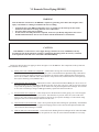
1
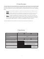
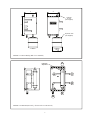
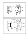
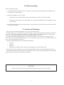
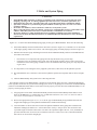
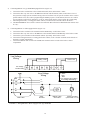
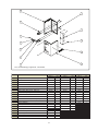
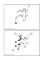
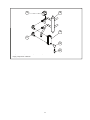
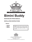
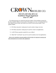
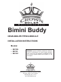
D
E S I G N E D
T O
L
E A D
Bimini Buddy
NEAR-BOILER PIPING MODULE
Installation INSTRUCTIONS
Models:
• BB100H
• BB100I
• BB100C
Warning: Improper installation, adjustment, alteration,
service or maintenance can cause property damage,
injury, or loss of life. For assistance or additional information, consult a qualified installer, service agency or the
gas supplier.
Manufacturer of Hydronic Heating Products
P.O. Box 14818 3633 I. Street
Philadelphia, PA 19134
www.crownboiler.com
Table of Contents
I. Product Description
II. Specifications
III. Before Installing
IV. Location and Mounting
V. Boiler and System Piping
VI. BB100C Domestic Water Piping VII. Wiring VIII. Start-up
IX. Parts
1
2
2
6
6
8
14
16
20
22
I. Product Description
The Bimini Buddy is a factory assembled near boiler piping module that is designed for use with Crown Bimini (BWC)
series boilers. The central component in this product is a hydraulic separator that is designed to assure that the minimum
required flow through the boiler is always maintained regardless of the flow through the heating system. This separator
is also used for air removal as well as the connection point for the expansion tank. There are four versions of the Bimini
Buddy:
•
BB100H - Provides hydraulic separation, air elimination, and expansion tank location for heat-only systems.
•
BB100I - In addition to BB100H features, the BB100I is also equipped with a 120VAC three way diverting
valve that allows the boiler output to be directed to either the heating system or an indirect water heater.
•
BB100C - In addition to BB100H features, the BB100C also includes a 120VAC three way diverting valve
that allows the boiler output to be directed to either the heating system or an integral plate heat exchanger for
domestic hot water (DHW) production. The BB100C is also equipped with a flow switch to initiate a call for
DHW production. DHW temperature is controlled by modulating the boiler supply temperature.
The Bimini Buddy has not been evaluated for use with any boilers not explicitly listed in Table 2.0.
II. Specifications
Table 2.0: Basic Specifications
Model
Compatible Boilers
Width (W), in.
Height (H), in.
Depth (D), in.
Weight, lbs
Max Expansion Tank Dia. (DM), in.
Maximum Operating Pressure
Maximum Operating Temperature
3-Way Valve Motor Rating
Flow Switch Set-point
Flow Switch contact Ratings
BB100H
BB100I
BB100C
BWC070 , BWC090, BWC120, BWC151
12
19-3/4
12-1/2
24
27
30
11
50 psi
200F
120VAC, 50/60Hz, 6.5W
(Energized for CH Demand)
0.50 GPM
20VA Pilot Duty at
120VAC
2
D
W
H
Automatic
Air Vent
(Not Supplied)
Expansion Tank
(Not Supplied)
DM
FIGURE 2.1: Bimini Buddy (With Cover Installed )
)
+\GUDXOLF
6HSDUDWRU
'
'
&
$
&
&
'
%
%
(
%
$
FIGURE 2.2: BB100H (Heat Only - Shown with Cover Removed)
3
Table 2.3: Connections
Key
A
B
C
D
E
Model
From Boiler Supply
To Boiler Return
To System
From System
Expansion Tank/Fill
BB100H
BB100I
1” Copper
1” MPT
1” Copper
1” Copper
1/2” FPT
F
Air Vent
1/2” FPT
G
To Indirect Water Heater
1” Copper
H
From Indirect Water Heater
1” Copper
I
J
DHW Inlet Connection
DHW Outlet Connection
BB100C
1/2” MPT
3/4” MPT
Table 2.4: BB100C DHW Performance
Approx. DHW Set
point Range
Boiler Model
BWC070
BWC090
DHW Production (GPM) Approximate
Response Time (s)
77 Rise
90F Rise
to 100F
to 120F
1.5
1.3
80
120
2.1
1.8
70
100
BWC120
BWC151
2.7
2.9
104 - 140
104 - 140
1.81
1.81
70
70
90
90
104 - 140
104 - 140
Table 2.4 Notes:
1. At 90 degree rise, boiler input (and therefore DHW production) is reduced due to proximity of DHW outlet
temperature to maximum permitted target supply temperature.
2. Response time is time required to reach specified temperature from a “cold start” with DHW inlet temperature of
58F and a 1.0 GPM draw rate. Additonal time may be required to purge the piping between the Bimini Buddy and
the fixture.
4
+\GUDXOLF
6HSDUDWRU
'
'
)
:D\
'LYHUWLQJ
9DOYH
&
*
&
+
'
&
%
%
(
%
$
FIGURE 2.5: BB100I (Indirect Water Heater - Shown with Cover Removed)
Hydraulic Separator
F
3 Way Diverting Valve
Plate Heat Exchanger
J
C
A
D
I
DHW Flow Switch
B
FIGURE 2.6: BB100C (Combi -Shown with Cover Removed)
5
E
III. Before Installing
Before installing this product:
1. Verify that the planned installation will be in accordance with all local codes. In Massachusetts, the BB100C must
be installed by a licensed Plumber.
2. When using the BB100C, also verify that:
•
The domestic water output temperature, and response times shown in Table 2.4 will be acceptable.
•
The domestic water hardness is less than 200ppm. If it is greater than 200PPM, do not use the BB100C without
a water softener.
3. When installing a BB100I, make sure that the indirect water heater has a pressure drop less than that shown in Table
5.4 at the flow rate shown.
IV. Location and Mounting
Select a location for the Bimini Buddy that is as close as possible to the boiler.
The Bimini Buddy can be located further away from the boiler as long as the maximum piping lengths shown in Tables
5.2, 5.3, or 5.5 are not exceeded. Keep in mind, however, that the response time of the BWC100C to a call for DHW
will increase as the length of piping between the boiler and Bimini Buddy is increased.
If possible install the Bimini Buddy slightly above the boiler so that there are no down turns in the supply piping
between the boiler and the Bimini Buddy (Figure 5.0) so as to facilitate air removal. If this is not possible, install a screw
driver vent in the supply piping (Figure 5.1).
Provide the following clearances for servicing the Bimini Buddy:
•
•
•
•
Front: 24”
LH Side: 6”
RH Side 1”
Top/Bottom: As needed in order to replace the field supplied air vent and expansion tank.
These clearances can be reduced, however servicing the Bimini Buddy will become increasingly difficult as they are.
Attach the Bimini Buddy to the wall using at last two suitable fasteners capable of supporting both it and the connected
piping using the obround slots in the top and bottom flanges. CAUTION
Drywall alone will not adequetly support the Bimini Buddy. Attach to studs or other framing.
6
THIS PAGE INTENTIONALLY LEFT BLANK
7
V. Boiler and System Piping
CAUTION
•
•
•
•
•
•
Install Bimini buddy and boiler so that the gas ignition system components are protected from water
(dripping, spraying, rain, etc) during appliance operation and service (circulator replacement, etc).
Install the boiler relief valve, and other boiler trim, as described in the boiler’s installation manual.
Operation of a boiler in a system having frequent additions of make-up water can cause severe heat
exchanger damage.
Do not use toxic additives, such as automotive antifreeze, in a hydronic system.
Before connecting boiler, make sure that the system is free of sediment, flux and any residual boiler water
additives. Flush the system if necessary to ensure that these contaminates are removed.
Do not use antifreeze or other chemicals that are not explicitly permitted by the boiler installation
manual. See the boiler installation manual for for additonal important information on water chemistry
requirements.
Figures 5.0 - 5.8 show basic Bimini Buddy Piping piping for all types of Bimini Buddies. Please note the following:
1) If the Bimini Buddy cannot be installed above the boiler as shown in Figure 5.0 (so that there are no down-turns
in the supply piping), install a screw driver vent in the supply piping for initial purging as shown in Figure 5.1.
2) Minimize the amount of pipe and fittings between the boiler and Bimini Buddy, and between the BB100I and
the indirect water heater:
•
•
Flow checks are not required in this piping and will only add unnecessary pressure drop.
If isolation valves are installed on the system side of the hydraulic separator, there is little reason to also
include them in the boiler piping. If isolation valves are installed in the boiler piping, use only full port ball
or gate valves.
3) If at all possible, avoid cutting the factory supplied system stubs (connections) on the hydraulic separator.
4) Recommended fill valve connection is between the hydraulic separator and expansion tank as shown in Figure
5.0.
5) Flush the Bimini Buddy and system before connecting the boiler
The hydraulic separator in the Bimini Buddy is designed to assure that the proper flow rate is maintained through the
boiler regardless of the flow rate present in the heating system. Even so, the piping between the boiler and Bimini Buddy
(and between the BB100I and the indirect water heater) must be properly sized for the boiler and Bimini Buddy to work
properly. Size this piping as follows:
1) All piping between the boiler and the Bimini Buddy (and between the Bimini Buddy and the indirect water
heater on the BB100I) is 1” nominal pipe size. For BB100I installations, this is true even when the indirect
water heater itself has different connection sizes.
2) Refer to the appropriate Figure 5.6, 5.7, or 5.8 for the type of Bimini Buddy being installed. Determine the
length of all straight pipe on the planned installation that is shaded in the drawing.
3) Count the number of elbows that will be used in the planned installation in the piping that is shaded in the
illustration. Multiply the number of 1” elbows that will be used by 2.75ft per elbow. The result is the total
equivalent length of all elbows that will be used. Note: the equivalent length of the Tee, Cross, and Reducers
provided with the boiler do not need to be considered. Likewise, Unions, runs of Tees, and Full Port Ball or
Gate Valves can be treated as straight pipe.
8
Automatic Air
Vent
System Circulator
Union
To Htg
System
Boiler Relief
Valve
From Htg
System
Fill Valve
Expansion Tank
Boiler Circulator
Drain Valve
FIGURE 5.0: Basic Bimini Buddy Field Piping (Bimini Buddy Shown Above Boiler to Faciliate Air Removal)
Screw Driver Vent
Automatic
Air Vent
Boiler Relief
Valve
System
Circulator
To Htg
System
From Htg
System
Fill Valve
Expansion Tank
Boiler Circulator
Drain Valve
FIGURE 5.1: Installation Of Bimini Buddy at Same Level as Boiler Using Screw Driver Vent
9
4) Add the total equivalent length of the elbows determined in step 3 to the to the total straight pipe length
determined in Step 2. The result is the total equivalent length.
5) Refer to Table 5.2, 5.3, or 5.5 as appropriate for the type of Bimini Buddy being installed. Verify that the
equivalent length calculated in Step 4 is less than that shown for the combination of boiler, circulator, and
indirect water heater (BB100I only) being installed. In the case of the BB100I, the pressure drop through the
indirect water heater must be considered. The indirect water heater being used must have a pressure drop less
than that shown in Table 5.3 at the DHW flow rate shown to work reliably with the BB100I. Table 5.4 shows
the pressure drop and flow information for Crown indirect water heaters. These are grouped by “class” and that
class is shown in Table 5.4.
Table 5.2: BB100H (Heat Only) Maximum Equivalent Boiler Loop Length
Boiler Model
BWC070
BWC090
BWC120
BWC120
BWC120
BWC151
BWC151
BWC151
Circulator
Taco 008
Taco 0014
Taco 0014
Taco 0014
Taco 0013
Taco 0014
Taco 0014
Taco 0013
Flow Rate
(GPM)
6.0
8.0
8.0
9.0
12.0
8.0
11.0
14.0
Max. Boiler Temp
Rise (F)
21
20
27
24
18
34
25
19
Pipe
Size
1”
1”
1”
1”
1”
1”
1”
1”
Max Equivalent Length of
Shaded Piping in Figure 5.6
179
121
152
80
37
92
54
45
Table 5.3: BB100I (IWH) Maximum Equivalent Boiler/IWH Loop Length
Boiler
Model
BWC070
BWC090
BWC120
BWC151
Circulator
Taco 008
Taco 0014
Taco 0014
Taco 0014
CH Mode
Flow
Max.
Rate
Boiler
(GPM)
Temp
Rise (F)
6.25
20
8.0
20
8.75
26
9.25
29
Flow
Rate
(GPM)
6.0
7.5
8.0
8.0
DHW Mode
Max. IWH
Indirect
Pressure Water Heater
Drop (ft
Class in
wc)
Table 5.4
1.7
A
2.6
A
3.0
A
5.0
B
Note
1
1
2
Pipe
Size
1”
1”
1”
1”
Max
Equivalent
Length of
Shaded Piping
in Figure 5.7
79
55
37
79
Notes:
1. “Class A” models shown in Table 5.4 may not achieve claimed first hour rating due to inadequate boiler water flow.
2. MS-79 will not achieve claimed first hour rating due to inadequate boiler output.
3. Some models shown in Table 5.4 have 3/4” boiler connections. These must be increased to 1” directly at the indirect
water heater connection.
Table 5.4: Crown Indirect Water Heaters
Indirect
Water
Heater
Class
A
B
Flow Rate
(GPM)
6.0
7.5
8.0
8.0
Max. IWH
Pressure
Drop (ft wc)
Crown Indirect Water Heater Models
1.7
MS-26, MS-40, MSH-40, MT040GBR, MT050GBR, MT050GBR,
2.6
MT065GBR, MT080GBR
3.0
5.0
MS-40, MS-53, MS-79, MSH-53
10
Table 5.5: BB100C (Combi) Maximum Equivalent Boiler Loop Length
Boiler
Model
BWC070
BWC090
BWC120
BWC151
Circulator
Taco 008
Taco 0014
Taco 0014
Taco 0014
CH Mode
Flow Rate
Max.
(GPM)
Boiler
Temp
Rise (F)
6.75
19
7.75
21
8.00
29
9.5
28
FIGURE 5.6: Boiler Loop Equivalent Length (Shaded) - BB100H
11
Pipe
Size
1”
1”
1”
1”
Max
Equivalent
Length of
Shaded Piping
in Figure 5.8
24
30
30
30
FIGURE 5.7 Boiler and IWH Loop Equivalent Length (Shaded) - BB100I
12
FIGURE 5.8: Boiler Loop Equivalent Length (Shaded) - BB100C/BB100M
13
VI. Domestic Water Piping (BB100C)
WARNING
Like all domestic water heaters, the BB100C is capable of generating water that is hot enough to cause
injury or death due to scalding. To minimize the risk of scalding:
•
•
•
Set domestic hot water (DHW) temperature as low as possible (see the Start-up Section of this
manual for information on setting domestic water temperature.
Feel water before showering or bathing.
If anti-scald or anti-chill protection is required, use devices specifically designed for such service.
Install and maintain these devices in accordance with the manufacturer’s instructions.
CAUTION
If the BB100C is connected to a water supply having a hardness in excess of 200PPM, scale may
prematurely form in the plate heat exchanger, significantly shortening its life. If necessary, soften the
water upstream of the cold water connection to the Bimini Buddy.
Connect the domestic hot water piping as shown in Figure 6.0 for the BB100C. The components in this system and
their functions are as follows:
1) Mixing Valve/Anti-scald Devices (Required) - A thermostatic mixing valve must be field supplied for the
BB100C. Where this mixing valve is field supplied, select a model that has an adjustment range which allows
it to be set below 120F (Honeywell AM-1 or equivalent). If required, install additional anti-scald protection
devices in accordance with local codes. In the absence of any local Codes, install such devices as required by
the Uniform Plumbing Code (IAPMO UPC).
2) Flow Restrictor (Recommended) - If domestic hot water is drawn from the Bimini Buddy at a rate in excess of
the rating in Table 2.4, the temperature of the hot water may be too low to be of use. The use of a flow restrictor
will prevent this problem by limiting the rate at which water can pass through the heat exchanger. If a restrictor
is used, select one having a rating in GPM approximately equal to that shown in Table 2.4.
z
3) Pressure Relief Valve (Required) - Limits the pressure in the domestic hot water piping. Use a valve designed
for DHW service, such as the Watts #3L or #53L. Note that this is a pressure relief valve, not a T&P valve.
Select a valve with a pressure setting less than or equal to 150 psi. Pipe the discharge to a safe location using
piping the same size as the discharge connection on the valve.
4) Hose Bib Valves (Recommended) - These valves permit the plate heat exchanger be periodically “back flushed”
to remove sediment. The BB100M is equipped with plugs which can be removed and replaced with hose bib
valves when the heat exchanger is cleaned.
5) Globe or Ball Valve (Recommended) - Used to aid in back flushing the heat exchanger and to isolate the DHW
piping if it must be serviced. In addition, the upstream valve may be used to limit the DHW flow if necessary.
14
To Fixtures
Hose Bib
Valve
Ball or Globe
Valve
Flow Restrictor
Thermostatic Mixing Valve
(Not Supplied)
DHW Relief Valve
(Max Setting 150 psi )
Hose Bib
Valve
Backflow Preventer
Cold Water In
FIGURE 6.0: BB100C Domestic Water Piping
15
VII. Wiring
WARNING
All wiring and grounding must be done in accordance with the authority having jurisdiction or, in the absence of
such requirements, with the National Electrical Code (ANSI/NFPA 70).
This manual covers wiring the Bimini Buddy into BWC series boilers using having two different control systems:
•
•
Control Systems using Honeywell Type III MCBA - This control system has been used on all BWC series
boilers manufactured between 2005 and late 2010. It uses an LED display.
Control Systems using Honeywell Sola - This control system is being phased in during 2010 and is
distinguished by a Panasonic touch screen display.
1) Connecting BB100H to Type III MCBA Equipped boilers (Figure 7.0):
a. Connect the boiler circulator to the red lead and neutral (white) in the Boiler’s J-Box. If the system has a single
system circulator, and the total combined current draw of the boiler and system circulators is less than 2.0A, the
system circulator can be wired in parallel to the boiler circulator. Otherwise, a relay (shown) or zoning panel
must be used to operate the system pump.
b. Connect the heating thermostat, or zoning panel boiler contacts, to terminals 1&2 on the boiler.
2) Connecting BB100H to Sola Equipped boilers (Figure 7.1):
a. Connect the boiler circulator to the terminals marked “BLR Pump” in the boiler’s J-Box.
b. Connect the system circulator to the terminals marked “Sys Pump” in the boiler’s J-Box.
c. Connect the heating thermostat, or zoning panel boiler contacts, to the “CH Stat” terminals on the left side of
the boiler’s control compartment.
3) Connecting BB100I to Type III MCBA Equipped boilers (Figure 7.2):
a. Connect the boiler circulator hot to the red lead and neutral (white) in the Boiler’s J-Box.
b. Connect the three way zone valve in the BB100I to the blue lead and neutral (white) in the boiler’s J-box. If
the system has a single system circulator having a draw of less than 1.5A, the system circulator can be wired in
parallel with the zone valve (after reprogramming the MCBA per part G of this manual, the zone valve will be
powered during a call for heat). Otherwise, a relay or zoning panel must be used to operate the system pump.
c. The heating thermostat, or zoning panel boiler contacts, are connected to terminals 1&2 on the boiler.
d. The indirect water heater’s thermostat is connected to terminals 7&8 on the boiler. IWH thermostat contacts
must be “dry”.
4) Connecting BB100I to Sola Equipped boilers (Figure 7.3):
a.
b.
c.
d.
Connect the boiler circulator to the terminals marked “BLR Pump” in the boiler’s J-Box.
Connect the three way zone valve in the BB100I to the terminals marked “DHW Pump” in the boiler’s J-Box.
Connect the system circulator to the terminals marked “Sys Pump” in the boiler’s J-Box.
Connect the heating thermostat, or zoning panel boiler contacts, to the “CH Stat” terminals on the left side of
the boiler’s control compartment.
e. Connect the indirect water heater’s thermostat to “DHW Stat” terminals on the left side of the boiler’s control
compartment.
16
Heating T-Stat
Low Voltage
Wiring
1
2
3
4
5
6
7
Line Voltage
Wiring
BK
Low Voltage
Terminal Strip
BK - Black
WT- White
R - Red
BL - Blue
Line Voltage Factory Wiring
Line Voltage Field Wiring
L1
WT
8
L2
WT
R
(N.O.)
BL
BWC J-Box
Relay 120 AC
(Field Supplied)
Boiler
Circulator
System Circulator
FIGURE 7.0: Wiring BB100H to Boiler equipped with Type III MCBA
Low Voltage
Terminal Strip
Line Voltage
Terminal Strip
CH
STAT
GND H
LINE
DHW
STAT
AUX
LIMIT
Heating T-Stat
OD
SENS
N
H
N
BLR
PUMP
H
N
DHW
PUMP
H N
SYS
PUMP
GND
L1
L2
HEAD
SENS
Low Voltage
Wiring
4-20
mA
Line Voltage
Wiring
FIGURE 7.1: Wiring BB100H to Boiler equipped with Sola
17
Boiler
Circulator
System
Circulator
5) Connecting BB100C to Type III MCBA Equipped boilers (Figure 7.4):
a. Connect the boiler circulator hot to the red lead and neutral (white) in the Boiler’s J-Box.
b. Connect the three way zone valve in the BB100I to the blue lead and neutral (white) in the boiler’s J-box. If
the system has a single system circulator having a draw of less than 1.5A, the system circulator can be wired in
parallel with the zone valve (after reprogramming the MCBA per part G of this manual, the zone valve will be
powered during a call for heat). Otherwise, a relay or zoning panel must be used to operate the system pump.
c. The heating thermostat, or zoning panel boiler contacts, are connected to terminals 1&2 on the boiler.
d. The BB100M/BB100C flow switch is connected to terminals 7&8 on the boiler. IWH thermostat contacts must
be “dry”.
6) Connecting BB100C to Sola Equipped boilers (Figure 7.5):
a.
b.
c.
d.
Connect the boiler circulator to the terminals marked “BLR Pump” in the boiler’s J-Box.
Connect the three way zone valve in the BB100C to the terminals marked “DHW Pump” in the boiler’s J-Box.
Connect the system circulator to the terminals marked “Sys Pump” in the boiler’s J-Box.
Connect the heating thermostat, or zoning panel boiler contacts, to the “CH Stat” terminals on the left side of
the boiler’s control compartment.
e. Connect the BB100C flow switch to the “DHW Stat” terminals on the left side of the boiler’s control
compartment.
Low Voltage
Wiring
Low Voltage
Terminal Strip
DHW T-Stat
Heating T-Stat
1
2
3
4
5
6
7
BK - Black
WT- White
R - Red
BL - Blue
Line Voltage Factory Wiring
Line Voltage Field Wiring
Line Voltage
Wiring
BK
L1
WT
L2
8
WT
R
ZV
BL
BWC J-Box
Boiler
Circulator
FIGURE 7.2: Wiring BB100I to Boiler equipped with Type III MCBA
18
BB100I 3-Way
Zone Valve
System Circulator
(Less Than 1.5 A )
Low Voltage
Terminal Strip
Heating T-Stat
CH
STAT
DHW T-Stat
DHW
STAT
Line Voltage
Terminal Strip
GND H
N
LINE
H
N
BLR
PUMP
H
N
DHW
PUMP
H N
SYS
PUMP
GND
AUX
LIMIT
L1
L2
OD
SENS
HEAD
SENS
Line Voltage
Wiring
zv
4-20
mA
Line Voltage
Wiring
Boiler
Circulator
BB100I 3 Way
Zone Valve
System Circulator
FIGURE 7.3: Wiring BB100I to Boiler equipped with Sola
Low Voltage
Wiring
Low Voltage
Terminal Strip
BB100C/M
Flow Switch
Heating T-Stat
1
2
3
4
5
6
7
BK - Black
WT- White
R - Red
BL - Blue
Line Voltage Factory Wiring
Line Voltage Field Wiring
Line Voltage
Wiring
BK
L1
WT
L2
8
WT
R
ZV
BL
BWC J-Box
Boiler
Circulator
BB100C/M 3-Way
Zone Valve
FIGURE 7.4: Wiring BB100C to Boiler equipped with Type III MCBA
19
System Circulator
(Less Than 1.5 A )
VIII Start-up
The following steps must be taken in addition to those shown in the boiler instruction manual in order to commission the
Bimini Buddy:
1) If not already done, flush the system so that it is free of sediment, flux and any residual boiler water
2) The Bimini Buddy must be purged of air. If it is piped in accordance with Figure 5.0, this can be done simply
by opening the fill valve and making sure that the automatic air vent is open. Otherwise, the screw driver vent
shown in Figure 5.1 must be also be opened until a steady stream of water comes from this vent. After this is
done, any residual air should remove itself through the automatic air vent over the first few days of operation.
3) The boiler’s control system must be “programmed” to operate the 3-way valve used on the BB100I, BB100C, (the boiler control system will operate the BB100H as is). The exact method for doing this depends on the type
of control system supplied with the boiler. Two control systems are used on BWC Series boilers, one employing
the Honeywell Type III MCBA and one Employing the Honeywell Sola. See Part VII of this manual for a
description of this two systems.
In the case of the BB100C, it is important to understand that the boiler does not monitor the DHW
temperature directly; instead it monitors, and regulates, the boiler supply temperature. The boiler supply
temperature tracks the DHW outlet temperature very closely.
A. BWC Boilers Equipped with Type III MCBA
Table 8.0: Type III MCBA Parameters for BB100I, BB100C
Parameter #
1
24
25
35
Description
Factory
Setting
135
10
6
13
DHW Set point
DHW Modulation Hysteresis On
DHW Modulation Hysteresis Off
DHW Configuration
BB100I
Setting
135
10
6
03
BB100C
Setting
110
-4
6
01
Parameter #35=13 (Factory Setting) - Red circulator lead is only powered on a call for heat. Blue circulator lead is
powered only upon a call for DHW. Call for DHW is initiated by a set of DHW thermostat contacts. When parameter
35=13, parameter 1 plus 46F = target supply temperature during a DHW call.
Parameter #35 =03 (BB100I) - Red circulator lead is powered upon either a heating or DHW demand. Blue lead is
powered only upon a heating demand. Call for DHW is initiated by a set of DHW thermostat contacts. When parameter
35=03, parameter 1 plus 46F = target supply temperature during a DHW call.
Parameter #35 =01 (BB100C) - Red circulator lead is powered upon either a heating or DHW demand. Blue lead is
powered only upon a heating demand. Call for DHW is initiated by the DHW flow switch. When parameter 35=01,
parameter 1 = target supply temperature during a DHW call.
Parameters #24 and #25 collectively work as a “differential” for the boiler supply temperature set point. Parameter #25
determines the difference above the supply temperature at which the burner shuts off. Parameter #24 defines how far
below the target temperature the supply temperature must fall before the burner turns back on. Since Table 8.0 defines parameter 24 as negative for the BB100C , the burner will actually restart when the supply temperature is still above the
target boiler supply temperature. For example, if the parameters are set as shown in Table 8.0 for the BB100C, the burner
will shut off when the supply temperature reaches 116F and restart when the supply falls to 114F.
20
/RZ9ROWDJH
7HUPLQDO6WULS
+HDWLQJ76WDW
%%&
)ORZ6ZLWFK
/LQH9ROWDJH
7HUPLQDO6WULS
&+
67$7
'+:
67$7
$8;
/,0,7
*1' +
1
/,1(
+
1
%/5
3803
+
1
'+:
3803
+ 1
6<6
3803
*1'
/
/
2'
6(16
+($'
6(16
]Y
P$
/RZ9ROWDJH
:LULQJ
/LQH9ROWDJH
:LULQJ
%RLOHU
&LUFXODWRU
%%&:D\
=RQH9DOYH
6\VWHP&LUFXODWRU
FIGURE 7.5: Wiring BB100C to Boiler equipped with Sola
WARNING
Improper setting of parameters can cause unreliable or unsafe operation, resulting in property damage, personal
injury, or loss of life:
•
•
•
•
Changing parameters should only be attempted by a professional heating service technician.
Do not change any parameters not described in this manual without first consulting the factory.
Before making changes, it is recommended that initial values of parameters be recorded so that they can
be restored if operation of the boiler is not as anticipated.
After changing any parameters, carefully confirm proper boiler operation before leaving the installation
site.
21
To change the parameters shown in Table 8.0, using the keypad on the boiler to do the following:
1) With the boiler powered, toggle the Mode key until you reach the (STBY) Standby mode.
2) Depress and hold the Step key and then quickly depress and hold the Mode key for 2 – 5 seconds until the
display reads (CODE). Release the Mode key, then the Step key. The display should show a ‘C’ followed by a
random two digit number.
3) Use the + or – keys to scroll to the number 05.
4) Press the Store key momentarily and watch for the display to blink twice. If the access code has been
successfully entered, access to Parameters 5 - 42 will be possible. Otherwise only Parameters 1-4 will be
accessible. Access to the expanded list of parameters will end and the access code will need to be reentered to
regain access to parameters 5-42.
5) Toggle the Mode key until you reach (PARA) Parameter mode.
6) Press the Step key to scroll through the parameters until you reach the desired parameters.
7) Use the + or – key to scroll to the appropriate parameter setting in Table 8.0.
8) Press the Store key momentarily and watch for the display to blink once. The parameter setting has now stored
its new value.
9) Parameter 1 can be accessed without entering a password. Follow steps 5-8 above to change Parameter #1.
In place of the keypad, the GCI PC interface can also be used to change the parameters in Table 8.0. See the Service
Supplement for BWC Series Boilers Equipped with Type III MCBA for instructions on how to do this.
B. BWC Boilers Equipped with Sola
Follow the instructions provided with the boiler and/or the boiler’s Configuration menu to select the type of Bimini
Buddy being used. Use the boiler’s setting menu to set the DHW target temperature.
IX. Parts
The replacement parts shown on the following pages can be obtained from any Crown distributor. To find the closest
Crown distributor, consult the area Crown representative or the factory at:
Crown Boiler Company
Customer Service
PO Box 14818
Philadelphia PA 19134
www.crownboiler.com
22
Cover and Mounting Components - All Models
Key
1
2
3
4
5
6
7
8
9
10
11
12
13
14
15
16
17
18
19
20
DESCRIPTION
Mounting Plate
Side Cover
Cover
Crown Aluminium Nameplate
Stainless Steel Acorn Nut 3/8"-16 Thread, 5/8" Height
#10x1/2 Truss Hd Screws
Clamping U-Bolt, Steel, 3/8"-16 FOR 2-1/2"
1" Copper Split Ring Hanger
Zinc-Plated Hex Nut 3/8"-16 Thread
5/16 Flat Washer
Cap Screw 3/8"-16 Thread, 1-1/4" Length, Fully Threaded
Extra-Thick Flat Washer 3/8" Screw,0.11"-0.13" Thick
BB100C
PART #
QTY
230751
1
230752
1
230750
1
98-044
1
230798
4
900120
11
230794
2
230790
3
90-221
3
900102
6
900452
3
230796
8
BB100I
PART #
230751
230752
230750
98-044
230798
900120
230794
230790
90-221
900102
900452
230796
QTY
1
1
1
1
4
11
2
3
3
6
3
8
Heat Only Separator
Combi Separator
230740
120V, Actuator, term block. AG13B020
230764
1
1
Female (Nut) Half 1" Swt Union, Elkahart#33584
230740
230764
230746
Hex Bend Assembly
230742
Heat Exchanger
230770
F3/4" x F1/2" Brass Reducing Elbow, NPT
230792
Flowswitch
230762
23
2
1
1
1
1
1
2
BB100H
PART #
QTY
230751
1
230752
1
230750
1
98-044
1
230798
4
900120
11
230794
2
230790
1
90-221
1
900102
2
900452
1
230796
8
230745
1
Piping Components - BB100H
'
'
&
&
%
%
$
Piping Components - BB100I
24
'
&
'
&
%
%
$
Piping Components - BB100C
25
Manufacturer of Hydronic Heating Products
P.O. Box 14818 3633 I. Street
Philadelphia, PA 19134
www.crownboiler.com
PN 980033 Rev. 11/04/11