1
CONTENTS
1 Introduction .............................................................................................................. 1
1–1
Objective ..................................................................................................................... 1
1–2
Recommended operation environment for the personal computer ............................. 1
1–3
Example of connecting the personal computer ........................................................... 1
1–4
Precautions on using the interface cable .................................................................... 1
1–5
Installing method ......................................................................................................... 2
1–5–1 File structure .................................................................................................................. 2
1–5–2 Installing procedures ..................................................................................................... 2
1–6
Copy of base data ....................................................................................................... 4
1–6–1 Copy procedures ........................................................................................................... 4
1–7
Installing the USB driver .............................................................................................. 5
1–7–1 Before installation .......................................................................................................... 5
1–7–2 Installation Procedure (Installing from the CD) .............................................................. 5
1–7–3 How to Change the COM Port ..................................................................................... 12
1–7–4 Uninstallation Procedure ............................................................................................. 14
2 Outline of functions ................................................................................................ 16
2–1
YZF-R6 ...................................................................................................................... 16
2–1–1 Function outline of the YEC FI Matching System ........................................................ 16
2–1–2 Targets for setting of the YEC FI Matching System and precautions .......................... 18
2–2
YZF-R1 ...................................................................................................................... 20
2–2–1 Function outline of the YEC FI Matching System ........................................................ 20
2–2–2 Targets for setting of the YEC FI Matching System and precautions .......................... 22
3 Quick -manual ........................................................................................................ 24
3–1
List of operations ....................................................................................................... 24
3–1–1 Editing and writing in of ECU data ............................................................................... 24
3–1–2 Editing of saved data in files and writing in ECU ......................................................... 24
3–1–3 Comparison of data saved in files and ECU data ........................................................ 25
3–2
Explanation of operations .......................................................................................... 26
3–2–1 Editing and writing in of ECU data ............................................................................... 26
3–2–2 Editing of data saved in files as well as writing in ECU ............................................... 30
3–2–3 Comparison of data saved in files and ECU data ........................................................ 31
4 Explanations of screens ......................................................................................... 33
4–1
Editing screen ............................................................................................................ 33
4–2
Function explanation ................................................................................................. 35
4–2–1 Graph editing function on MAP screen ........................................................................ 35
4–2–2 MAP editing function on TABLE screen ...................................................................... 35
4–2–3 Selecting of plural cells, editing, copy function on the TABLE screen ......................... 35
4–2–4 Pasting function of plural cell data on TABLE screen ................................................. 36
5 Pull down menu ..................................................................................................... 37
5–1
File ............................................................................................................................. 37
5–1–1 Open ............................................................................................................................ 37
5–1–2 Close ........................................................................................................................... 38
5–1–3 Save as... .................................................................................................................... 38
5–1–4 Directory... ................................................................................................................... 38
5–1–5 Exit .............................................................................................................................. 38
5–2
Edit ............................................................................................................................ 39
5–2–1 Undo ............................................................................................................................ 39
5–2–2 Copy ............................................................................................................................ 39
5–2–3 Paste ........................................................................................................................... 39
5–3
Monitor ...................................................................................................................... 40
5–3–1 Monitor ........................................................................................................................ 40
5–3–2 Item set ........................................................................................................................ 40
5–4
Tool ........................................................................................................................... 41
5–4–1 Com ............................................................................................................................. 41
5–4–2 Title .............................................................................................................................. 42
5–4–3 Edit Const .................................................................................................................... 42
5–4–4 Read from ECU ........................................................................................................... 43
5–4–5 Write to ECU ............................................................................................................... 43
5–4–6 Data Compare ............................................................................................................. 44
5–5
Window ...................................................................................................................... 45
5–5–1 All ................................................................................................................................ 45
5–5–2 Monitor Dialog ............................................................................................................. 45
5–6
Help ........................................................................................................................... 46
1
Introduction
1–1
Objective
This in an instruction manual on the YEC FI Matching system (YMS)
1–2
Recommended operation environment for the personal computer
CPU
: Pentium 500 MHz equivalent or higher
Memory
: 256 MB or above
OS
: Windows XP US edition, Japanese language edition
Recommended monitor resolution : 1024 x 768 or higher
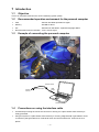
1–3
Example of connecting the personal computer
Interface cable
Vehicle
harness
4-pin connector
USB
A-type
Computer
1–4
Precautions on using the interface cable
Avoid directly touching the end of the connector or storing it in a place where static electricity is
easily generated.
Using this system in a place where static electricity or a strong magnetic field is generated or close
to machinery that generates a lot of electrical noise can lead to malfunction. Avoid use in such
places.
–1–
1–5
Installing method
1–5–1 File structure
As base data folder, prepare YMS_Data folder
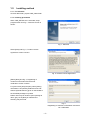
1–5–2 Installing procedures
When YMS_SETUP.exe is executed, setup
program starts and Fig. 1. Welcome screen is
shown.
Fig. 1: Welcome
Select [Next] and Fig. 2., Product License
Agreement screen is shown.
Fig. 2: Product License Agreement
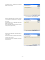
[Select [Next] and Fig. 3, Registering of
customer's information and serial No.
certification screen is shown.
For [User name] and [Company name] setting
information is acquired by default from the OS
while the [Serial Number.] given on the booklet in
the CD-ROM package is inputted.
Neither item may be omitted. Upon inputting all
items, gray-out of [Next] is released and
selecting may be made.
Fig. 3:
Registering of customer's information and serial
No. certification
–2–
Click [Next] and Fig. 4, Selecting of the installing
folder screen is shown.
Fig. 4: Selecting of the installing folder
Select the destination folder in which the system
is to be installed. The default value is "\Program
Files \YMS".
Select [NEXT] and Fig. 5, Selecting of base data
folder screen is shown.
Specify folder Path optionally by [Path] or specify
existing folder by [Directories].
Fig. 5: Selecting of base data folder
Select the base data folder. The default value is
"\YMS_Data".
When [Change] button is pressed, the Selecting
of folder screen is shown.
Select [NEXT] and Fig. 6, Installation confirming
screen is shown.
Fig. 6: Installation confirmation.
–3–
Select [Install] and installation starts. Upon
finishing installation, Fig. 7 Setup completion
screen is shown.
Fig. 7: Set up completion
When [Finish] is pressed, setup in completed.
Upon finishing setup, "YEC FI Matching System"
shortcut is displayed on desktop and on start
menu. Program maybe started from this
shortcut.
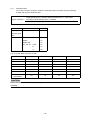
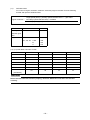
1–6
Copy of base data
1–6–1 Copy procedures
Copy the base data stored in the installed CD to
“C:\YMS_DATA” manually.
Base data
Model year
Model
Name of base data
KIT ECU
2006
YZF-R6
R6-06_BaseData_00.ycz
2C0-8591A-70
2007
YZF-R6
R6-07_BaseData_00.ycz
2C0-8591A-71
2008
YZF-R6
R6-08_BaseData_00.ycz
2C0-8591A-80
2009
YZF-R6
R6-09_BaseData_00.ycz
2C0-8591A-90
2010
YZF-R6
R6-10_BaseData_00.ycz
2C0-8591A-91
2011
YZF-R6
R6-11_BaseData_00.ycz
2C0-8591A-92
2007
YZF-R1
R1-07_BaseData_00.ycz
4C8-8591A-70
2008
YZF-R1
R1-08_BaseData_00.ycz
4C8-8591A-80
2009
YZF-R1
R1-09_BaseData_00.ycz
14B-8591A-70
2010
YZF-R1
R1-10_BaseData_00.ycz
14B-8591A-71
2011
YZF-R1
R1-11_BaseData_00.ycz
14B-8591A-72
CAUTION:
Any combination of base data and ECU not shown above will generate an error.
Always use one of the above combinations.
–4–
1–7
Installing the USB driver
1–7–1 Before installation
Installation of the USB driver is required when connecting the interface cable to your computer for the
first time. Connection to the ECU is not required when installing the driver.
* There are two installation methods.
(1)
Install from the CD.
(2)
If you cannot use the CD when you connect the interface cable for the first time, copy the driver
files from the CD onto the computer and then specify the driver files to install them.
The driver files are in the “KITUSBCDM 2.02.04 FTDI DRIVER” folder on the CD. Copy the
whole folder onto the computer.
* The appearance of screens may differ depending the type of PC in use.
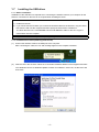
1–7–2 Installation Procedure (Installing from the CD)
(1)
Connect the interface cable to the USB port of the computer.
After connecting the cable, an icon and message appear in the computer’s task bar.
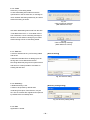
(2)
Insert the CD in the CD drive. When the “Found New Hardware Wizard” screen appears and asks
“Can Windows connect to Windows Update to search for software?” select “No, not this time” and
click “Next”.
–5–
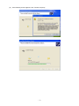
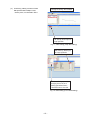
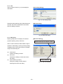
(3)
Check “Install from a list or specific location” and click “Next”.
(4)
Check “Search for the best driver in these locations” and “Search removable media (floppy, CDROM...)” and then click “Next”.
* When installing from driver files copied onto your computer, check “Include this location in the
search” and select the folder where the files are saved.
–6–
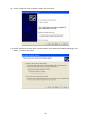
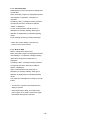
(5)
If the following screen appears, click “Continue Anyway”.
–7–
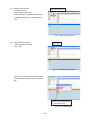
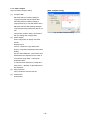
(6)
When the “Completing the Found New Hardware Wizard” screen appears, click “Finish”.
Installation of the USB driver is now complete.
After clicking “Finish”, please wait. Installation of the serial port driver will soon start.
–8–
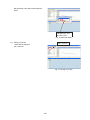
(7)
Serial port driver installation
After the USB driver is installed, the following message appears in the task bar.
(8)
When the “Found New Hardware Wizard” screen appears, check “No, not this time” and click
“Next”.
–9–
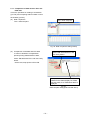
(9)
Check “Install from a list or specific location” and click “Next”.
(10) Check “Search for the best driver in these locations” and “Search removable media (floppy, CDROM...)” and then click “Next”.
– 10 –
(11) If the following screen appears, click “Continue Anyway”.
(12) When the “Completing the Found New Hardware Wizard” screen appears, click “Finish”.
All installation is now complete.
– 11 –
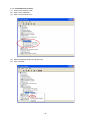
1–7–3 How to Change the COM Port
When two or more devices using serial ports are installed on a computer, the COM ports increase.
(COM4, 5, 6...)
If you want to select an optional COM number, you can change it with the device manager.
Changing procedure
(1)
Connect the interface cable.
(2)
Right click on “My Computer” and open “Properties”.
(3)
In “Properties”, open “Hardware” and “Device Manager”.
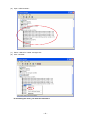
(4)
Open “Ports (COM and LPT)”, select the desired serial port and right click to open “Properties”.
(5)
Select “Port Settings” and click “Advanced”.
– 12 –
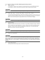
(6)
Select the desired COM port in “COM Port Number” and click “OK”.
Close the Device Manager and reopen it. The COM number is now changed.
CAUTION:
In the above screen, some COM numbers may be marked “in use”.
These are COM numbers that have been registered once to another device.
Selecting one of them now will write over the existing setting, so you may have to reset the
original device when you next use it.
– 13 –
1–7–4 Uninstallation Procedure
(1)
Connect the interface cable.
(2)
Open “Device Manager”.
(3)
Open “Ports (COM & LPT)”.
(4)
Select the desired serial port and right click.
(5)
Click “Uninstall”.
– 14 –
(6)
Open “USB Controller”.
(7)
Select “USB KIT IF Cable” and right click.
(8)
Click “Uninstall”.
* If reinstalling the driver, you must first uninstall it.
– 15 –
2
Outline of functions
The following functions are seen in the YMS.
To read data from ECU, edits fuel adjusting map and ignition map, and writes in ECU.
To read saved data, and after confirming the contents and editing, writes in ECU.
To read saved data, and compares with ECU data or other saved data.
2–1
YZF-R6
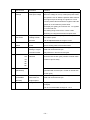
2–1–1 Function outline of the YEC FI Matching System
(1)
Map items
Functions
Contents
Shifter / Cut Time
Sets ignition cut time
Setting possible by each gear within scope of 0
by each gear
to 150 ms.
When shifter/cut time (***)=0 ms is set, the
selected gear flameout control can be
ineffective.
(2)
Comp. FUEL /
Adjusts A/F
Corrects fuel amount by increasing-decreasing
Map 1
within range of ±30%
Effective at 1,000 rpm and higher (Not
(3)
corrected at less than 1000 rpm)
Comp. FUEL /
Map 1 or Map 2 can be selected with the map
Map 2
switch. (Contact open: Map 1, contact closed:
Map 2)
(4)
Offset IGNITION
Corrects ignition time
Corrects ignition timing within range of -15° CA
to 5° CA
Effective at 3000 rpm and above. (Does not
make corrections at less than 3000 rpm).
(5)
Comp. ETV /
Corrects ETV opening
Corrects basic ETV opening within a range of
Acceleration
(Acceleration
-100% to 0%.
correction)
Example: Suppress torque by inputting -20% to
the area of high opening at low revolution.
(6)
Comp. ETV /
Corrects ETV opening
Corrects basic ETV opening between 0 and 50
Engine Brake
(Engine brake
steps
correction)
(Automatically limits to a maximum value within
the ECU by an operating range).
Enables adjustment at different engine speeds
(and independently for each gear)
(7)
Comp. FUEL / All
Area
Adjusts A/F
Has same function as (2) Comp. Fuel and
makes uniform correction of operation areas.
Corrects increase-decrease of fuel amount
within a scope of ±30%.
– 16 –
(8)
Const items
Functions
Contents
Shifter / On
Sets speed shift
Adjusting the Level of Shifter Control Starting Voltage
Voltage
start input voltage
When the voltage is over (or under) the preset value,
the ignition is cut off. With the positive value at which
the engine torque is through, the ignition is cut off
over the preset value and with the negative value the
ignition is cut off under the preset value.
(Example) 2V: Igniting is cut off over 2V. -2V: Ignition
is cut off under 2V.
The setting range covers from -5.00 to 4.96V.
Switching on using the kit harness requires 2.5V.
(9)
(10)
(11)
(12)
Comp. RAM
Adjusts A/F
Entered if there is discrepancy of A/F compared with
Correction
relating to Ram
the vehicle speed.
pressure
Can be adjusted within the range of ±10%.
Rev. Limiter
Corrects revolution
Can be corrected within a range of -1000 rpm to 0
Offset
limiter
rpm to existing value of revolution limiter.
Pit Road Limiter
For pit load control
Set within range of EG revolution range between
Setting of engine
2000 and revolution limit rpm.
revolution limiter
Only effective in first and second gear.
Transmission
Transmission selection function
selection
Enter the ratio of each gear (number of wheel teeth/
Gear Ratio 1st
2nd
number of pinion teeth)
3rd
4th
5th
6th
(13)
Number of teeth
Enter the number of teeth on the wheel side of the
(6th/Wheel)
gear fitted with a sensor. (No. of teeth on wheel side
of sixth gear)
(14)
(16)
VI
VI starts operating.
Set within range of EG revolution range between
(VARIABLE
Determine the
5000 and revolution limit rpm.
INTAKE)
engine speed.
Comp. IDL
Idling correction
Idling correction function (=Engine brake also
changes)
Can be corrected within a range of -1 to 2.
– 17 –
2–1–2 Targets for setting of the YEC FI Matching System and precautions
(1)
Shifter / Cut Time
In case ignition cut time is short: Shift loss is reduced but there may cause hard gear throws.
In case ignition cut time is long: Gear throws will be easier but shift loss will increase.
CAUTION:
If ignition cut time is too short, the drive system may be damaged.
(2)
Comp. FUEL / Map 1 (3) Comp. FUEL / Map 2 (7) Comp. FUEL / All Area
It is recommended that adjustment be made while constantly checking A/F. Aim for A/F 12 to 13.
Change at one time should be changes of 2% to 5% and especially for changes on the reduction
side, (in case of becoming thinner), pay attention to the A/F value while changing.
CAUTION:
If A/F is too thin, may relate to damage of the engine.
(4)
Offset IGNITION
Adjust to the spark advancing side if too excessive, may possibly damage the engine. Sufficient
care is needed when making adjustment. In case no change is seen when spark advancing is
selected, or when at a loss to which side adjustment should made, it is recommended that
adjustment be made to the spark retarding side.
CAUTION:
Adjusting to the spark advancing side may possibly damage the engine if too extreme.
(6)
Comp. ETV / Engine Brake
CAUTION:
If open setting of the throttle is made to reduce engine braking, the engine revolution may not
drop enough at corners and over-speeding may risk causing of serious accidents. Especially, a
change in gear ratio, or the running on a course for the first time, will require paying of sufficient
attention.
(9)
Comp. RAM Correction
Use only when the A/F diverges with increased vehicle speed.
– 18 –
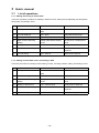
(11)
Pit Road Limiter
For control of engine revolution, obtain the necessary engine revolution from the following
formula and input the obtained value.
Target speed (km/h) × (Primary speed reduction ratio × 1st gear ratio ×
Engine revolution =
secondary speed reduction ratio) × 1000000
60 × tire periphery (mm)
YZF-R6
Model
Gear ratio
2.07
Primary
reduction gear
ratio
1st gear ratio
STD
2.58
'06KIT
2.16
'06KIT-OP
2.31
'07, '08, '09
A KIT
2.31
B
2.47
C
2.58
(12), (13) Gear Ratio / Number of teeth
YZF-R6
STD
A
B
C
Gear Ratio 1st
2.58
2.31
2.47
2.58
Gear Ratio 2nd
2.00
1.86
1.95
2.00
Gear Ratio 3rd
1.67
1.57
1.61
1.67
Gear Ratio 4th
1.44
1.39
1.44
1.47
Gear Ratio 5th
1.29
1.27
1.30
1.35
Gear Ratio 6th
1.15
1.14
1.15
1.18
23
25
23
26
Number of teeth
(6th/Wheel)
CAUTION:
Set the mission selection function properly, otherwise Shifter/Cut Time does not function
correctly.
– 19 –
2–2
YZF-R1
2–2–1 Function outline of the YEC FI Matching System
(1)
Map items
Functions
Contents
Shifter / Cut Time
Sets ignition cut time
Setting possible by each gear within scope of 0
by each gear
to 150 ms.
When shifter/cut time (***)=0 ms is set, the
selected gear flameout control can be
ineffective.
(2)
Comp. FUEL /
Adjusts A/F
Corrects fuel amount by increasing-decreasing
Map 1
within range of ±30%
Effective at 1,000 rpm and higher (Not
(3)
corrected at less than 1000 rpm)
Comp. FUEL /
Map 1 or Map 2 can be selected with the map
Map 2
switch. (Contact open: Map 1, contact closed:
Map 2)
(4)
Offset IGNITION /
Corrects ignition time
Map1
Corrects ignition timing within range of -15° CA
to 5° CA
Effective at 3000 rpm and above. (Does not
(5)
make corrections at less than 3000 rpm).
Offset IGNITION /
The map switch lets you change between Map
Map2
1 and Map 2 (Switch open: Map1, Switch
closed: Map 2)
(6)
Comp. ETV /
Corrects ETV opening
Corrects basic ETV opening between 0 and 50
Engine Brake
(Engine brake
steps
correction)
(Automatically limits to a maximum value within
the ECU by an operating range).
Enables adjustment at different engine speeds
(and independently for each gear)
(7)
Comp. FUEL / All
Area
Adjusts A/F
Has same function as (2) Comp. Fuel and
makes uniform correction of operation areas.
Corrects increase-decrease of fuel amount
within a scope of ±30%.
– 20 –
(8)
Const items
Functions
Contents
Shifter / On
Sets speed shift
Adjusting the Level of Shifter Control Starting Voltage
Voltage
start input voltage
When the voltage is over (or under) the preset value,
the ignition is cut off. With the positive value at which
the engine torque is through, the ignition is cut off
over the preset value and with the negative value the
ignition is cut off under the preset value.
(Example) 2V: Igniting is cut off over 2V. -2V: Ignition
is cut off under 2V.
The setting range covers from -5.00 to 4.96V.
Switching on using the kit harness requires 2.5V.
(9)
(10)
(11)
(12)
Comp. RAM
Adjusts A/F
Entered if there is discrepancy of A/F compared with
Correction
relating to Ram
the vehicle speed.
pressure
Can be adjusted within the range of ±10%.
Rev. Limiter
Corrects revolution
Can be corrected within a range of -1000 rpm to 0
Offset
limiter
rpm to existing value of revolution limiter.
Pit Road Limiter
For pit load control
Set within range of EG revolution range between
Setting of engine
2000 and revolution limit rpm.
revolution limiter
Only effective in first and second gear.
Transmission
Transmission selection function
selection
Enter the ratio of each gear (number of wheel teeth/
Gear Ratio 1st
2nd
number of pinion teeth)
3rd
4th
5th
6th
(13)
Number of teeth
Enter the number of teeth on the wheel side of the
(6th/Wheel)
gear fitted with a sensor (No. of teeth on wheel side
of sixth gear)
(14)
(16)
VI
VI starts operating.
Set within range of EG revolution range between
(VARIABLE
Determine the
5000 and revolution limit rpm.
INTAKE)
engine speed.
Comp. IDL
Idling correction
Idling correction function (=Engine brake also
changes)
Can be corrected within a range of -1 to 2.
– 21 –
2–2–2 Targets for setting of the YEC FI Matching System and precautions
(1)
Shifter / Cut Time
In case ignition cut time is short: Shift loss is reduced but there may cause hard gear throws.
In case ignition cut time is long: Gear throws will be easier but shift loss will increase.
CAUTION:
If ignition cut time is too short, the drive system may be damaged.
(2)
Comp. FUEL / Map 1 (3) Comp. FUEL / Map 2 (7) Comp. FUEL / All Area
It is recommended that adjustment be made while constantly checking A/F. Aim for A/F 12 to 13.
Change at one time should be changes of 2% to 5% and especially for changes on the reduction
side, (in case of becoming thinner), pay attention to the A/F value while changing.
CAUTION:
If A/F is too thin, may relate to damage of the engine.
(4)
Offset IGNITION / Map 1 (5) Offset IGNITION / Map 2
Adjust to the spark advancing side if too excessive, may possibly damage the engine. Sufficient
care is needed when making adjustment. In case no change is seen when spark advancing is
selected, or when at a loss to which side adjustment should made, it is recommended that
adjustment be made to the spark retarding side.
CAUTION:
Adjusting to the spark advancing side may possibly damage the engine if too extreme.
(6)
Comp. ETV / Engine Brake
CAUTION:
If open setting of the throttle is made to reduce engine braking, the engine revolution may not
drop enough at corners and over-speeding may risk causing of serious accidents. Especially, a
change in gear ratio, or the running on a course for the first time, will require paying of sufficient
attention.
(9)
Comp. RAM Correction
Use only when the A/F diverges with increased vehicle speed.
– 22 –
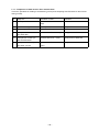
(11)
Pit Road Limiter
For control of engine revolution, obtain the necessary engine revolution from the following
formula and input the obtained value.
Target speed (km/h) × (Primary speed reduction ratio × 1st gear ratio ×
Engine revolution =
secondary speed reduction ratio) × 1000000
60 × tire periphery (mm)
YZF-R1
Model
Gear ratio
1.512
Primary
reduction gear
ratio
1st gear ratio
2.533
STD
'07, '08, '09
A KIT
2.429
B
2.357
C
2.313
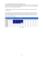
(12), (13) Gear Ratio / Number of teeth
YZF-R1
STD
A
B
C
Gear Ratio 1st
2.53
2.43
2.36
2.31
Gear Ratio 2nd
2.06
2.13
2.00
1.94
Gear Ratio 3rd
1.76
1.82
1.74
1.61
Gear Ratio 4th
1.52
1.60
1.52
1.48
Gear Ratio 5th
1.36
1.47
1.41
1.36
Gear Ratio 6th
1.27
1.33
1.32
1.27
33
28
33
33
Number of teeth
(6th/Wheel)
CAUTION:
Set the mission selection function properly, otherwise Shifter/Cut Time does not function
correctly.
– 23 –
3
3–1
Quick -manual
List of operations
3–1–1 Editing and writing in of ECU data
This is the operation procedure for reading in data from ECU, editing the fuel adjusting map and ignition
timing map, and writing in ECU.
No.
Objective
Operation of YMS
(1)
Startup of YMS
Double click for shortcut to
Remarks
YMS
(2)
ycz File reading in
File > Open
Only YMS exclusive file
(3)
Reading in data from ECU
Tool > Read from ECU
Keep power to ECU ON.
(4)
Data content confirming,
Editing optional data of Map/
At this point, not reflected on
editing
Const.
ECU
(5)
Writing in data in ECU
Tool > Write to ECU
Keep power to ECU ON.
(6)
Title information editing
Tool > Title
Edit Title information as
required
(7)
ycz File saving
File > Save as
Store file as required
3–1–2 Editing of saved data in files and writing in ECU
This is the procedure for reading in saved data (ycz File), checking contents, editing, and writing in ECU.
No.
Objective
Operation of YMS
(1)
Startup of YMS
Double click for shortcut to
Remarks
YMS
(2)
ycz File reading in
File > Open
Only YMS exclusive file
(4)
Data content confirming,
Editing optional data of Map/
At this point, not reflected on
editing
Const.
ECU
(5)
Writing in data in ECU
Tool > Write to ECU
Keep power to ECU ON.
(6)
Title information editing
Tool > Title
Edit Title information as
required
(7)
ycz File saving
File > Save as
– 24 –
Store file as required
3–1–3 Comparison of data saved in files and ECU data
This is the operation for reading in saved data (ycz File) and comparing with ECU data or other saved
data (ycz File).
No.
Objective
Operation of YMS
(1)
Startup of YMS
Double click for shortcut to
Remarks
YMS
(2)
ycz File reading in
File > Open
Only YMS exclusive file
(8)
Data comparison
Tool > Data Compare
(9)
Comparison of edited data
Edit area with ECU > Verify
Keep power to ECU ON.
File data with ECU > Verify
Keep power to ECU ON.
Comparison of editing data
Edit area with File data >
Only exclusive file for YMS
and other ycz File.
Verify
and ECU data.
(10)
Comparison of other ycz
File and ECU data.
(11)
– 25 –
3–2
Explanation of operations
3–2–1 Editing and writing in of ECU data
This is the operation procedure for reading in
data from ECU, editing fuel adjusting Map and
ignition typing map, and writing in ECU.
(1)
Startup of YMS
Double click short-cut to YMS on desk top
Double click
"YEC FI Matching System"
“YEC FI Matching System.”
Also may click
"YEC FI Matching System"
on the task bar.
Fig. 8: startup of YMS
(2)
Reading in ycz File
File > open First, read in the ycz File of the
applicable model in.
File > Open
Fig. 9: Reading in of ycz File
(3)
Reading in data from ECU.
Tool > Read from ECU
Tool>Read from ECU
* At this time, keep power to ECU ON.
Read in is completed when “Complete” is
displayed. Click “OK.”
Fig. 10: Reading in data from ECU
– 26 –
(4)
Confirming, editing contents of data
Change to editing desired MAP
Edit optional data of Map/ Const.
* At this point, not reflected in ECU.
Edit data by direct input or
Page Up/Down
Fig. 11: Data editing (Map data editing)
Edit data by direct input
or Page Up/Down
Edit Const dialog opens by
changing Const tab and
clicking operational items.
* Tool>Edit Const also OK.
Fig. 12: Data editing (Const data editing)
– 27 –
(5)
Writing in data to ECU
Tool > Write to ECU
Tool>Write to ECU
* Keep power to ECU ON.
When “Data Write Complete Finished OK!!”
is displayed, writing in is completed. Click
“OK.”
Fig. 13: Write in data to ECU
(6)
Title information editing
Tool > Title
* Title is edited as required.
Tool > Title
Fig. 14: Title Editor dialog startup
Select item on which editing is desired and
click edit button for dialog startup of the edit
title.
Select desired editing item
and click Edit button.
Fig. 15: Title Editor dialog
– 28 –
Edit optionally. Click OK to edit respective
items
Edit optionally, and
click OK button
Fig. 16: Edit Title dialog
(7)
Saving of ycz File
File > Save as
* Save files as required.
File > Save as
Fig. 17: Saving of ycz File
– 29 –
3–2–2 Editing of data saved in files as well as
writing in ECU
This is the operation procedure when reading in
saved data (ycz File), confirming of contents,
then after editing, writing in the ECU.
(1)
Startup of YMS is in accordance with 3-2-1,
same as editing and writing in ECU data
(2)
Read in ycz File.
Read in saved file,
Fig. 18: Read in of ycz File
(3)
Read in of data from ECU is not required
when editing data saved in file.
(4)
Data content confirming editing
Change to Const tab, and confirm
contents of the Const side data
Confirm that contents of data of Map/Const
is the data desired for writing in ECU and
edit if necessary.
Changeover to Map and confirm that
the contents of data are correctly
those desired for writing in ECU.
* At this point, not reflected in ECU.
Conduct (5) Writing in data to ECU, (6) Title
information editing (7) Saving of ycz File
after data editing by the same procedure
with that of 3-2-1. Editing and writing of
ECU data.
Confirm that contents of data are those
correctly desired for writing in ECU.
Fig. 19: Data content confirming editing.
– 30 –
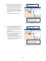
3–2–3 Comparison of data saved in files and
ECU data
This is the operation for reading in saved data
(ycz File) and comparing with ECU data or other
saved data (ycz File).
(8)
Data comparison
Tool > Data Compare
Tool > Data Compare
Fig. 20: Data comparison dialog startup
(9)
Comparison of edit data and ECU data
Select "Edit area with ECU" and
click Verify button.
In case it is desired to compare data
presently being edited with ECU data,
select “Edit area with ECU” and click Verify
button.
* At this time, keep power to ECU ON.
If compared data matches, "Same" is
indicated in the status display but if data
does not match, then "Difference label" is
displayed.
Fig. 21:
Data compare dialog (Edit area with ECU)
– 31 –
(10) Comparison of other ycz File and ECU data
Select "File data with ECU" and
click Verify button.
In case it is desired to compare other ycz
File and ECU data while leaving data
presently being edited as it is, select “File
data with ECU” and click Verify button.
Open the open file dialog and specify the
other ycz Files desired for comparison with
ECU members.
* At this time, keep power to ECU ON.
If compared data matches, "Same"
is indicated in the status display but
if data does not match, then
"Difference label" is displayed.
Fig. 22:
Data compare dialog (File data with ECU)
(11) Comparison of Edit data with other ycz File
Select "Edit area With File Data"
and click Verify button.
In case it is desired to compare data
presently being edited with other ycz File,
select “Edit area with File data” and click
Verify button.
The Open File dialog opens. Specify the
other ycz File which you desire to compare
with data presently being edited.
* ”Edit area With File Data” does not
conduct ECU communication because of
comparison between the data presently
being edited and the ycz File.
If compared data matches, "Same"
is indicated in the status display but
if data does not match, then
"Difference label" is displayed.
Fig. 23:
Data Compare dialog (Edit area with File data)
– 32 –
4
Explanations of screens
4–1
Editing screen
(1) Title bar
(2) Tool bar
(3) Map change list
Change by Page Up/down key or by mouse
Cursor point
(5) All display change
Move by arrow key or mouse
Move by arrow key or mouse
(6) Button for increase/decrease of data
Fig. 24: Editing screen
(1)
Title bar
Opened file names are shown by directory name on title bar.
(2)
Tool bar
From the left
Open
:File-Open
Save
:File-Save
Copy
:Edit-Copy
Paste
:Edit-Paste
Undo
:Edit-Undo
Read from ECU :Tool-Read data from ECU
Write to ECU
:Tool - Write data to ECU
Edit Const
:Tool-Open Edit Const dialog
(3)
Map change list
Map tab: Displays a list of labels of MAPs to be edited, and when the cursor is pointed to a Label,
the Map of the Label is displayed on the MAP window and on the Label MAP.
Const tab: Displays Const. List which may be edited. When list is clicked. Edit Const. dialog is
opened.
– 33 –
(5)
ALL display change
When checked, all lines of the MAP graph are displayed and when the check is removed, only the
selected lines are displayed.
(6)
Button for increase/decrease of data
Button: Data of selected cell are reduced by tenfold of minimum increments
Button: Data of selected cell are reduced by minimum increments
Button: Data of selected cell are increased by tenfold of minimum increment
Button: Data of selected cell are increased by minimum increments
– 34 –
4–2
Function explanation
4–2–1 Graph editing function on MAP screen
Data editing function on graph point
Clicking on graph: Graph is selected and also the editing point of the revolution nearest to the
clicked point is selected.
Drag and drop of graph data: Edit point is selected with left button down. By moving up and down,
changed to the editing point nearest to the release point. (Direction of revolution is not changed)
4–2–2 MAP editing function on TABLE screen
Editing by key inputting is possible. When a value outside the data settable range is imputed, a warning
message dialog is displayed and a value for which data settable value is automatically set.
* When a figure key or minus key is inputted, becomes in a cell editing status and key inputting status.
Also becomes in a cell editing status by double clicking of the mouse.
Editing of axis cell
Revolution axis, throttle opening axis may both be numerically inputted or may be changed by
[Page Up]/[Page Down] keys. The input value is limited by the maximum input range or by the value
of the adjacent cell value.
CAUTION:
The Comp. FUEL / Map 1 axis and Comp. FUEL / Map 2 axis (engine rotation and throttle opening)
are common. When either one is changed, the same value is reflected on the other.
4–2–3 Selecting of plural cells, editing, copy function on the TABLE screen
When in a status with cursor at an optional cell, drag by mouse and a plural cell selecting status is seen.
* When a numerical key or minus key is inputted, becomes in a cell editing status with key inputting
status. Double clicking of the mouse releases multiple cell selection and becomes in cell editing status.
– 35 –
4–2–4 Pasting function of plural cell data on TABLE screen
Data array copied in a plural cell selecting status may be pasted by {Ctrl} + {V} key on any optional cell
other than the revolution increment and throttle opening increment axis cells. Also, plural cell data copied
from Excel, etc. may be pasted via the clip board.
* However, when plural cell data is copied on the clip board, posting cannot be made in a plural cell
selecting status.
In case pasting of data array exceeding the cell range in which pasting on the Table is attempted, the
data exceeding the pasting possible range is ignored, The pasted data is consistently rounded to a
minimum increment figure. In case of values outside the data settable range, the limit value within the
settable range is automatically set.
Fig. 25: Table
– 36 –
5
Pull down menu
5–1
File
Open
Ctrl+O
••Open data file
Close
••Close file to which read in made
Save as...
••Attach name and save.
Directory...
••Display directory setting dialog
Exit
Alt+F4
••End YMS
* Close, Save, as...care not displayed in the pull down menu until read in of data file is made.
5–1–1 Open
Open ycz File.
[Open dialog]
Fig. 26: Open dialog
– 37 –
5–1–2 Close
Close the ycz File being edited.
In case data editing was made from the file
opened time or the file save time, a message to
check whether data being edited may be closed
without file saving is shown.
Fig. 27:
Close confirming message
(With difference to file)
Also when data editing was made from the time
"Tool>Read from ECU" or "Tool>Write to ECU
was conducted, a close confirming message is
shown to check whether closing may be made
without writing to EUC of data being edited.
Fig. 28:
Close confirming message
(With difference to ECU)
5–1–3 Save as...
A name is attached to the ycz File being edited
[Save as dialog]
and saved.
A Windows standard Save As dialog opens for
saving with a name attached to the file.
File being edited may be given an optional name
and saved. It is also possible to overwrite an
existing file and save.
Fig. 29: Save As dialog
5–1–4 Directory...
A Default directory is set.
[Directory setting dialog]
A folder to be opened by default when
conducting File>Open, File>Save as, may be
set. The set contents are registered and opened
by default at the next startup time.
Fig. 30: Directory setting dialog
5–1–5 Exit
Application is ended.
– 38 –
5–2
Edit
Undo
Ctrl+Z
••Return
Copy
Ctrl+C
••Copy
Paste
Ctrl+V
••Paste
5–2–1 Undo
When data is changed or revised with the data
editing screen, the changes are cancelled.
The data change information for Undo is kept by
each Map.
5–2–2 Copy
Cell data selected on the Table Display screen is
stored in the clip board.
With plural cell selected status, the selected
plural cell data is saved in the clipboard.
5–2–3 Paste
Pastes data in the clip board by the Table
Display screen.
In case there is a copied data array of plural cell
selected status in the clip board, array data is
pasted in plural in the right downward direction
from the cell with the cursor. Data which is
crowded out from the Table display screen
become invalid.
– 39 –
5–3
Monitor
Monitor...
Ctrl+M
Item set...
••Monitor dialog is displayed
••Item setting dialog of the monitor is displayed.
5–3–1 Monitor
Processed value inside ECU is displayed
simplified. Functions at less than 4000 rpm by a
simplified monitor for function confirming
(diagnosis) such as input sensor, etc. Since it is
not a real time display, transient changes cannot
be confirmed.
(1)
Start button
Starts communications. When
communication is started, the inscription
changes to "Stop." When pressed during
Fig. 31: Monitor dialog
communications, communication is ended
and the inscription returns to "Start." Also,
communication ends when the dialog is
closed.
5–3–2 Item set
Open set monitor data dialog and set Items.
(1)
List of items
(2)
List of monitor dialog items
[Set monitor data dialog]
(2) Addition/deletion of items to be inputted
on monitor screen.
>>[A] Addition of items
Items to be outputted to
monitor screen
<<[D] Deletion of items
Items selected as monitor dialog items are
automatically stored when YMS.exe is ended.
(1) List of items
Fig. 32: Set monitor data dialog
– 40 –
5–4
Tool
Com...
••Com port selecting dialog is displayed
Title...
••Title setting dialog is displayed
Edit Const...
••Edit Const dialog is displayed
Read from ECU
••ECU data is read in as editing data.
Write to ECU
••Data being edited is written in ECU
Data Compare...
••Data compare dialog is displayed
5–4–1 Com
Selection of Communications port
A KIT interface cable (13S-8533A-70) is required
for communication with a KIT-ECU. Select the
Com port by the setting procedure as follows:
Record COM No.
Setting procedure
Automatic setting function
(1)
Check “Auto Select” in the Com Port setting
dialog of the YMS.
Fig. 33
Manual setting
(If normal communication is not achieved with
the automatic setting function, Com Port can be
set manually.)
(1)
Connect the interface cable to the
[Com Port setting dialog]
computer.
(2)
Right-click on "My Computer" and open
"Properties".
(3)
From "Property", open "Hardware" and then
"Device manager".
(4)
Record the USB Serial Port COM number.
(5)
Uncheck "Auto Select" in the Com Port
setting dialog of the YMS.
(6)
Designate the Communications port
number recorded in the YMS
Communications port dialog box and click
on OK. That concludes the setting.
Fig. 34: Com Port setting dialog
– 41 –
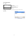
5–4–2 Title
Items of [Title] of set file (*.ycz) are displayed
[Title setting dialog]
and edited.
Fig. 35: Title setting dialog
Data items being edited by title setting dialog are
[Edit title dialog]
selected and when the Edit button is pressed,
Edit Title dialog is opened.
Fig. 36: Edit Title dialog
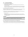
5–4–3 Edit Const
Display [Calib] items and display and edit the
[Edit Const dialog]
physical quantity (value) of the item.
Decimal data input and display screen
When a value outside the data settable range in
inputted in data editing, warning message dialog
is displayed and a limit value within the settable
range is automatically set.
(2)
Undo button
Undoes the editing contents
(3)
OK button
(2)
Finalizes the editing contents and closes
the dialog.
(4)
Cancel button (X button)
Move by arrow key.
Scraps the editing contents without
Fig. 37: Edit Const Dialog
finalizing and closes the dialog.
– 42 –
(3)
(4)
5–4–4 Read from ECU
Reads data from ECU and writes in editing area
as edit data.
When executed, progress is displayed and when
data reading is completed, "Complete" is
indicated.
If reading in fails, a message reading "Failed to
correspond with ECU, Read Error Address
:XXXX " is displayed.
In case communication with other ECU is
attempted, a message reading "ECU type is
different" is displayed by model distinguishing
check.
Each message closes by pressing OK button.
* When the monitor dialog is opened, this
function cannot be executed.
5–4–5 Write to ECU
Write in editing area data to ECU.
When executed, progress is displayed and when
data reading in I completed, message reading
"Data Write Compete Finished OK!!" is
displayed.
If reading in fails, a message reading "Failed to
correspond with ECU, Write Error Address:
XXXX" is displayed.
When communication with other ECU is
attempted, a message reading "ECU type is
different" is displayed by model distinguishing
check.
The respective messages are closed by the OK
button.
* This function cannot be executed while the
dialog is opened.
* After transferring of data, shut off the ECU
power supply once. When switched on again,
the transfer data become effective.
– 43 –
5–4–6 Data Compare
Open the Data Compare dialog.
(1)
[Data Compare Dialog]
Compare With
Edit area with ECU: Making setting to
compare edit area data and ECU data.
File data with ECU: Making setting to
(1)
(2)
compare data of ycz File with data of ECU.
Edit area with File data: Making setting to
compare data being edited with data of ycz
(3)
File.
Fig. 38: Data Compare Dialog
Verify button; Read in data in accordance
with the setting and compare data.
(2)
Status display
Press verify button to display executed
results.
Display format
1st line, comparison origin data name
2nd line, comparison destination data name
display
3rd line and subsequent, Label names with
data differences. Displayed in the order of
"comparison origin data," "comparison
destination data,"
In case there are differences in Map data.
"Map name,"; "Number of data differences"
are displayed.
(3)
Save log button
Verify results are saved in text file.
(4)
Close button
Close dialog.
– 44 –
(4)
5–5
Window
All
Alt+A
•• Change All displays and Single displays of graph displayed on
Map screen.
Monitor Dialog
•• Shift cursor to Monitor screen when Monitor screen is being
displayed.
5–5–1 All
Change Graph displayed on the Map screen to
All and Single. In the All status, menu checking is
made. The same action is taken with F4 also.
5–5–2 Monitor Dialog
Shift cursor to Monitor screen when the Monitor
screen is being displayed.
– 45 –
5–6
Help
Open Version dialog to display version
[Version dialog]
information.
Fig. 39: Version dialog
– 46 –
Published by YAMAHA MOTOR ENGINEERING co., LTD