1
’08 YZF-R6
SS KIT MANUAL
The Performance Edge
for excellent riders
Introduction
• Please understand that these parts are not covered by warranty.
• The manufacturer does not take any responsibility for problems caused by these parts.
• These kit parts are intended exclusively for racing purposes. You are strictly requested not
to use them on public roads.
• The specifications and usage methods of these kit parts along with the contents of this
manual are subject to change without notice for improvement.
• This manual is intended for persons with knowledge and experience of motorcycles. Please
refer to the YZF-R6 service manual, which shall be published from YAMAHA MOTOR
CO.LTD., for information on part assembly and maintenance.
• The design of the YZF-R6 racing kit is based on YZF-R6, according to FIM racing rules, but
that does not mean the kit conforms to all competitions.
When used in races, riders must mount the YZF-R6 racing kit at their own discretion after
checking the rules of competition issued by the sponsor.
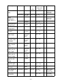
Parts List Symbols
• The star mark (*) means that the part is included in the kit set and is a genuine Yamaha
part. Therefore, you can easily purchase the part at any Yamaha part dealer when
necessary.
• The circle mark (°) means that when needed, the individual part is sold separately to the kit set.
No.
PART No.
PART NAME
Q'TY
*
1
2C0-11181-76
GASKET, CYLINDER HEAD
3
*
2
2C0-11603-00
PISTON RING SET
12
*
3
93450-16159
CIRCLIP
24
4
2C0-1165A-00
*
5
90179-07001
*
6
*
7
˚
8
2C0-13414-70
GASKET, STRAINER
3
ANTI STICK TYPE
˚
9
2C0-15451-70
GASKET, CRANKCASE
COVER 1
3
ANTI STICK TYPE
BOLT, CONNECTING ROD
24
NUT
24
4SV-12119-00
SEAL, VALVE STEM OIL
48
2C0-12213-00
GASKET, TENSIONER
3
REMARKS
t=0.45mm
Symbol Marks
The information necessary for correct handling and inspections and maintenance is shown with
the following symbol marks.
CAUTION:
This indicates the possibility of injury or material damage occurring if
mishandled.
NOTE:
This shows the method for correct operation and the points for
inspection and maintenance.
CONTENTS
1 Engine Specifications................................................................................... 1
2 Kit Parts ......................................................................................................... 2
2-1 Engine Parts.................................................................................................... 2
1.
2.
3.
4.
5.
6.
7.
8.
9.
10.
11.
12.
13.
14.
15.
16.
17.
18.
19.
20.
Maintenance Set (2C0-MAINT-71) ....................................................................... 2
Spark plug set (5FL-R045Q-70)............................................................................ 3
Head Gasket ......................................................................................................... 4
Cam Shaft and Cam Sprocket .............................................................................. 5
Valve Spring Set (2C0-A2110-70) ........................................................................ 6
Oil Pump (2C0-13300-70)..................................................................................... 6
Air Funnel Set (2CO-A4460-80)............................................................................ 6
Throttle Body Clamp Assembly (2CO-1351A-70) ................................................. 8
AIS Plug Set (13S-A4890-70) ............................................................................... 9
Clutch Spring Set (2CO-A6330-70) .................................................................... 11
Friction Plate Set (2CO-A6321-70) ..................................................................... 11
Slipper Clutch Setting Set (4B1-A6377-70) ........................................................ 12
Transmission Gear.............................................................................................. 15
Mission Maintenance Set (2C0-A7000-70) ......................................................... 19
Drive Sprocket .................................................................................................... 22
Sprocket Nut Set (2C0-A7463-70) ...................................................................... 23
ACM Set (2C0-F1400-71) ................................................................................... 24
Wire Harness Set (13S-F2590-70) ..................................................................... 25
ECU Set (2C0-8591A-80) ................................................................................... 28
Cable Interface (13S-8533A-70) ......................................................................... 29
2-2 Vehicle Accessories..................................................................................... 32
21.
22.
23.
24.
25.
26.
27.
28.
29.
30.
Engine Protector Set (2C0-A5491-70) ................................................................ 32
Chassis Protector Set (2C0-C117G-70) ............................................................. 33
Oil Catch Tank Set (2C0-C1707-80)................................................................... 35
Front Fork Spring Set.......................................................................................... 36
Steering Damper Stay Set (2C0-C3495-80) ....................................................... 38
Seat Cushion (13S-24713-70) ............................................................................ 39
Front Spare Wheel Assembly (2C0-25100-70)................................................... 40
Rear Spare Wheel Assembly (2C0-25300-70) ................................................... 41
Throttle Set (2C0-C6300-70) .............................................................................. 42
Throttle Set (13S-C6300-70)............................................................................... 43
3 Tightening Torque List ............................................................................... 44
4 YZF-R6 Wiring Diagram.............................................................................. 57
1 Engine Specifications
Spec
Displacement
599cc
Maximum engine speed
(limiter controlled speed)
16000rpm
Bore/Stroke
67.0 × 42.5mm
Valve timing (event angle)
INT.
EXT.
= 110°
= 110°
Squish height
0.60mm
Clearance between the valve and the piston
INT.
EXT.
= 1.10 12° ATDC
= 1.62 12° BTDC
Clearance of valves (tappet)
INT.
EXT.
–1–
= 0.20 targeted (0.18 – 0.22)
= 0.25 targeted (0.23 – 0.27)
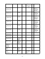
2 Kit Parts
2-1 Engine Parts
1.
Maintenance Set (2C0-MAINT-71)
Parts List
No.
PART No.
PART NAME
Q'TY
*
1
2C0-11181-76
GASKET, CYLINDER HEAD
3
*
2
2C0-11603-00
PISTON RING SET
12
*
3
93450-16159
CIRCLIP
24
4
2C0-1165A-00
BOLT, CONNECTING ROD
24
*
5
90179-07001
NUT
24
*
6
4SV-12119-00
SEAL, VALVE STEM OIL
48
*
7
2C0-12213-00
GASKET, TENSIONER
3
°
8
2C0-13414-70
GASKET, STRAINER
3
ANTI STICK TYPE
°
9
2C0-15451-70
GASKET, CRANKCASE
COVER 1
3
ANTI STICK TYPE
°
10
2C0-15461-70
GASKET, CRANKCASE
COVER 2
3
ANTI STICK TYPE
°
11
2C0-15456-70
GSKT., 1
3
ANTI STICK TYPE
*
12
93102-35017
SEAL, OIL
3
FOR DRIVE AXLE
*
13
90151-06024
SCREW,
CROSSRECESSED
COUNTERSUNK
9
FOR BEARING
HOUSING
–2–
REMARKS
t=0.45mm
2.
Spark plug set (5FL-R045Q-70)
Parts List
No.
PART No.
1
5FL-94700-70
PART NAME
PLUG, SPARK
Q'TY
4
REMARKS
NGK R0045Q-10
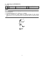
NOTE:
Since these spark plugs have a copper gasket, caution is needed during installation on
the following points.
1. The tightening torque is 10 – 12 N•m (1.0 – 1.2 kgf•m).
2. When not checking the torque, tighten by rotating through 30° after manual
tightening in the case of new plugs. When reusing plugs, tighten by rotating through
15°.
–3–
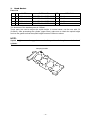
3.
Head Gasket
Parts List
No.
PART No.
PART NAME
Q'TY
REMARKS
1
2C0-11181-71
GASKET, CYLINDER HEAD
1
t=0.40mm
2
2C0-11181-76
GASKET, CYLINDER HEAD
1
t=0.45mm
3
2C0-11181-81
GASKET, CYLINDER HEAD
1
t=0.50mm
4
2C0-11181-86
GASKET, CYLINDER HEAD
1
t=0.55mm
The thickness of the standard parts is 0.60mm.
These parts are used to adjust the squish height. In normal cases, use the one with -76
(0.45mm). After processing the cylinder (upper case), make sure to check the squish height
and use the gasket so that the squish height becomes 0.60mm or above.
NOTE:
Squish height means the gap between the flat portion of the piston and the head
cylinder.
Stamping location
–4–
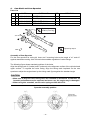
4.
Cam Shaft and Cam Sprocket
Parts List
No.
PART No.
PART NAME
Q'TY
1
2C0-12171-71
SHAFT, CAM 1
1
2
2C0-12181-71
SHAFT, CAM 2
1
3
2C0-12176-70
SPROCKET, CAM 1
1
4
2C0-12177-70
SPROCKET, CAM 2
1
REMARKS
Tightening torque
24 N•m (2.4 m•kg)
STD
Tightening torque
FWD.
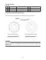
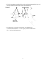
Assembly of Cam Sprocket
For the cam sprocket for racing kit, there are 5 mounting holes at the angle of ±1° and ±2°
against standard mounting. Use of these holes enables regulation of valve timings.
The following figure shows standard positions of the holes.
Align the timing mark of I (intake) and E (exhaust) to the alignment surface of the cylinder head
upper surface. To regulate the valve timing, align the timing mark imprinted on the cam
sprocket to adjust the angle shown by the timing mark figure against the standard angle.
CAUTION:
• Make sure to align the valve timing when the camshaft is assembled. If otherwise, no
intended performance can be expected and more over, the engine may be damaged.
• When using this camshaft, use the valve spring set 2C0-A2110-70.
Sprocket assembly position
–5–
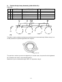
5.
Valve Spring Set (2C0-A2110-70)
Parts List
No.
PART No.
PART NAME
Q'TY
REMARKS
1
2C0-12113-70
SPRING,1
8
For 2C0-12171-71 (INT)
2
2C0-12114-70
SPRING,2
8
For 2C0-12181-71 (EXT)
3
2C0-12117-70
RET., VALVE SPRING
16
• This set will be effective in improving the engine performance and durability if it is provided
exclusively for the kit cam shaft and used in combination.
CAUTION:
When using this valve spring, use the camshafts 2C0-12171-71, and 2C0-12181-71.
6.
Oil Pump (2C0-13300-70)
Parts List
No.
PART No.
1
2C0-13300-70
PART NAME
OIL PUMP ASSY
Q'TY
REMARKS
1
• This pump is capable of a larger discharge than the STD counterpart.
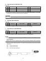
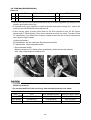
7.
Air Funnel Set (2CO-A4460-80)
Parts List
No.
PART No.
1
PART NAME
FUNNEL
Q'TY
2
REMARKS
L=15.9mm
• This set is capable of higher intake efficiency than the STD counterpart.
NOTE:
• The air cleaner case is fastened by the STD funnel. Remove the STD funnel and
mount the plate.
• Apply a thin amount of grease to the screws of the funnel and plate before attaching.
This set is made by MG Competition. For details of the specification, please check with MG
TEL
+33 (0) 4 50 25 59 96
FAX
+33 (0) 4 50 25 59 98
Web
http://www.mgcompetition.fr/
L=15.9
Competition.
–6–
Reference
Standard
L=25.9
Selecting the Funnel
In addition to the funnel set in the KIT, the ycci system mounted on the STD vehicle can also be
used. This is capable of being controlled (in operation timing etc.) by the use of YMS software
accompanying KIT ECU. (ycci control is possible by using 2 kinds of basic control data (SS
spec and ST spec) included in KIT ECU.
–7–
8.
Throttle Body Clamp Assembly (2CO-1351A-70)
Parts List
No.
PART No.
PART NAME
Q'TY
*
1
90450-56005
HOSE CLAMP ASSY.
4
*
2
95307-04600
NUT, HEX.
3
3
5SL-13573-70
BOLT, 1
2
4
5SL-1358A-70
ROD COMP.
1
5
2C0-13573-70
BOLT, 1
1
REMARKS
This part is used to enhance maintenance performance of the throttle body. Before using it, cut
off the protrusion for positioning bands at the cabjoint.
Cut it off
The part has a collar to prevent over-tightening. In normal cases, the part will not be tightened
till it reaches to the collar. Just manually tighten it.
Make sure to put a new band through a M4 x 0.7 tap before using it.
–8–
9. AIS Plug Set (13S-A4890-70)
This plug set is used when the AIS (Air Induction System), an exhaust gas purification system,
is removed.
Parts List
*
No.
PART No.
PART NAME
Q'TY
1
5SL-1482L-70
PLATE, 2
2
2
93608-16M16
PIN, DOWEL
4
3
90336-10020
PLUG, TAPER
1
REMARKS
Installation
1. Remove the hose attached to the cylinder head cover and the air cut-off valve assembly
accompanying the hose.
2. Remove the cap fitted to the hose and remove the reed valve and plate from the inside.
3. Install the plate (5SL-1482L-70) in replacement of the cap. Apply liquid gasket to the plate.
4. Remove the cylinder head cover and the four collars fitted to the cover. Install the PIN
(93608-16M16).
5. After removing the hose connected to the air cleaner case from the air-cut valve assembly,
open the upper case of the air cleaner case and insert the PLUG (90336-10020) into the
hole where the hose was connected.
–9–
STD
A/C ASSY.
REMOVE
KIT
Insertion
direction
!
A/C ASSY.
– 10 –
10. Clutch Spring Set (2CO-A6330-70)
Parts List
No.
PART No.
1
2C0-16334-70
PART NAME
SPRING, CLUTCH 2
Q'TY
REMARKS
6
The clutch spring has a 20% higher mounting load on the STD.
11. Friction Plate Set (2CO-A6321-70)
Parts List
No.
PART No.
1
5EB-16321-72
PART NAME
PLATE, FRICTION 1
Q'TY
9
Compared to STD, the friction plate enhances durability and operation.
Identification Paint (Violet)
– 11 –
REMARKS
12. Slipper Clutch Setting Set (4B1-A6377-70)
Parts List
No.
PART No.
*
1
4B1-16377-70
NUT, LOCK
1
*
2
4B1-16391-70
SHIM
3
a
PART NAME
2
Q’TY
REMARKS
1
c
b
42.4 – 43.0
– 12 –
(Setting of back torque limiter of clutch).
A clutch with a back torque limiter mechanism is installed in the YZF-R6 SP engines. The
operation of the back torque limiter can be adjusted through adjusting: 2 the number of SHIMs
(set up for the kit); a the number of springs; b the whole thickness of the clutch plate; and the
strength of c spring (set up for the kit) of the slipper clutch setting set.
(Recommended setting method)
To begin with, the dimensions of the clutch are re-set to the standard values. (For details,
please refer to the service manual published from YAMAHA MOTOR CO. LTD.
When the 1 2 slipper clutch setting sets are to be installed, and the number of the SHIMs are
to be three in stack, the setting may be carried out according to the standard.
c Spring may be selected from either one of the kit parts or the standard parts. Spring load of
the kit parts is designed to increase in 10% as compared with that of the standard parts.
– 13 –
When installing the kit parts, the back torque limiter tends not to be effective (Engine braking
becomes more effective).
When decreasing the number of SHIMs (standard setting is three) of slipper clutch setting set,
the back torque limiter tends to be effective (Engine braking becomes less effective).
Standard
3
2
1
0
effective
(Engine braking becomes
less effective)
Further, when decreasing the number of a spring (the number of standard setting is three) to
two, the back torque limiter becomes effective (Engine braking becomes less effective).
CAUTION:
When decreasing the number of a spring to two, the caution should be taken to surely
use three pieces of SHIMs for the slipper clutch setting set. If its number being less than
the above, the less load may be supported so as to exert serious influences on driving.
Decreasing the number of a spring to one is not allowed.
3 a springs,
3 SHIMs
3 a springs,
2 SHIMs
3 a springs,
1 SHIM
Load
3 a springs,
0 SHIM
2 a springs,
3 SHIMs
As installed
In operation
Stroke
– 14 –
13. Transmission Gear
Parts List
No.
PART No.
1
2C0-17411-80-A
AXLE, MAIN
1
A
1
2C0-17411-90-B
AXLE, MAIN
1
B
*
1
2C0-17411-00
AXLE, MAIN
1
C
*
2
2C0-15163-00
HSG., BEARING
1
*
3
93306-20562
BRG.
1
4
2C0-17151-71-A
GEAR, 5TH PINION
1
A
4
2C0-17151-80-B
GEAR, 5TH PINION
1
B
4
2C0-17151-90-C
GEAR, 5TH PINION
1
C
5
2C0-17131-80-A
GEAR, 3RD PINION
1
A
5
2C0-17131-71-B
GEAR, 3RD PINION
1
B
5
2C0-17131-90-C
GEAR, 3RD PINION
1
C
6
2C0-17161-70-A
GEAR, 6TH PINION
1
A
6
2C0-17161-00
GEAR, 6TH PINION
1
B
6
2C0-17161-90-C
GEAR, 6TH PINION
1
C
7
2C0-17121-80-A
GEAR, 2ND PINION
1
A
7
2C0-17121-90-B
GEAR, 2ND PINION
1
B
7
2C0-17121-00
GEAR, 2ND PINION
1
C
8
2C0-17402-70
DRIVE, AXLE ASSY.
1
*
9
2C0-17421-00
AXLE, DRIVE
1
*
10
93305-20509
BRG.
1
*
11
90387-25016
COLLAR
1
12
2C0-17221-81-A
GEAR, 2ND WHEEL
1
A
12
2C0-17221-90-B
GEAR, 2ND WHEEL
1
B
12
2C0-17221-00
GEAR, 2ND WHEEL
1
C
13
2C0-17261-71-A
GEAR, 6TH WHEEL
1
A
13
2C0-17261-80-B
GEAR, 6TH WHEEL
1
B
13
2C0-17261-90-C
GEAR, 6TH WHEEL
1
C
14
2C0-17241-80-A
GEAR, 4TH WHEEL
1
A
14
2C0-17241-70-B
GEAR, 4TH WHEEL
1
B
14
2C0-17241-90-C
GEAR, 4TH WHEEL
1
C
15
2C0-17231-80-A
GEAR, 3RD WHEEL
1
A
15
2C0-17231-70-B
GEAR, 3RD WHEEL
1
B
15
2C0-17231-90-C
GEAR, 3RD WHEEL
1
C
16
2C0-17251-71-A
GEAR, 5TH WHEEL
1
A
16
2C0-17251-80-B
GEAR, 5TH WHEEL
1
B
16
2C0-17251-90-C
GEAR, 5TH WHEEL
1
C
17
2C0-17211-80-A
GEAR, 1ST WHEEL
1
A
17
2C0-17211-90-B
GEAR, 1ST WHEEL
1
B
*
*
*
PART NAME
– 15 –
Q'TY
REMARKS
Parts List
*
No.
PART No.
PART NAME
17
2C0-17211-00
Q'TY
GEAR, 1ST WHEEL
1
REMARKS
C
17
15
16
14
13
12
9
1
2
8
10
3
11
4
5
6
7
• Gear Ratio
std
A
B
C
1st
31/12 (2.583)
37/16 (2.313)
42/17 (2.471)
31/12 (2.583)
2nd
32/16 (2.000)
39/21 (1.857)
39/20 (1.950)
32/16 (2.000)
3rd
30/18 (1.667)
36/23 (1.565)
29/18 (1.611)
30/18 (1.667)
4th
26/18 (1.444)
25/18 (1.389)
26/18 (1.444)
28/19 (1.474)
5th
27/21 (1.286)
33/26 (1.269)
30/23 (1.304)
27/20 (1.350)
6th
23/20 (1.150)
25/22 (1.136)
23/20 (1.150)
26/22 (1.182)
CAUTION:
• No gear can be used for the kit transmission except for the specified STD gear.
• There is no compatibility with the ’06 model transmission set (2C0-A7400-70).
– 16 –
YZF-R6 Mission ratio
Pinion gear
GEAR PLAN Ratio
1ST
2ND
3RD
4TH
5TH
6TH
Part number
Wheel gear
The Stamp
number
of teeth
Part number
The Stamp
number
of teeth
A
2.313 2C0-17411-80-A
16
A
2C0-17211-80-A
37
A
B
2.471 2C0-17411-90-B
17
B
2C0-17211-90-B
42
B
C
2.583
12
2C0-17211-00
31
A
1.857 2C0-17121-80-A
21
A
2C0-17221-81-A
39
A
B
1.950 2C0-17121-90-B
20
B
2C0-17221-90-B
39
B
C
2.000
16
2C0-17221-00
32
A
1.565 2C0-17131-80-A
23
A
2C0-17231-80-A
36
A
B
1.611 2C0-17131-71-B
18
B
2C0-17231-70-B
29
B
C
1.667 2C0-17131-90-C
18
C
2C0-17231-90-C
30
C
A
1.389 2C0-17131-80-A
18
A
2C0-17241-80-A
25
A
B
1.444 2C0-17131-71-B
18
B
2C0-17241-70-B
26
B
C
1.474 2C0-17131-90-C
19
C
2C0-17241-90-C
28
C
A
1.269 2C0-17151-71-A
26
A
2C0-17251-71-A
33
A
B
1.304 2C0-17151-80-B
23
B
2C0-17251-80-B
30
B
C
1.350 2C0-17151-90-C
20
C
2C0-17251-90-C
27
C
A
1.136 2C0-17161-70-A
22
A
2C0-17261-71-A
25
A
B
1.150
20
2C0-17261-80-B
23
B
C
1.182 2C0-17161-90-C
2C0-17261-90-C
26
C
2C0-17411-00
2C0-17121-00
2C0-17161-00
22
C
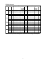
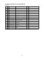
Make sure that the pinion and wheel gear are combined for use according to the chart plan.
– 17 –
– 18 –
20
22
B
22
A
C
23
20
26
A
B
19
C
C
18
B
18
18
C
A
18
23
A
B
16
C
21
A
20
12
C
B
17
16
P
B
A
PLAN
26
23
25
27
30
33
28
26
25
30
29
36
32
39
39
31
42
37
W
1.182
1.150
1.136
1.350
1.304
1.269
1.474
1.444
1.389
1.667
1.611
1.565
2.000
1.950
1.857
2.583
2.471
2.313
Ratio
46
16
47
16
48
16
45
15
49
16
46
15
50
16
47
15
51
16
48
15
45
14
52
16
49
15
46
14
50
15
47
14
51
15
48
14
52
15
49
14
50
14
51
14
52
14
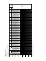
97.4
95.5
275.7 269.7 264.0 258.5 258.5 253.2 252.9 248.2 247.5 243.3 242.3 241.3 238.6 237.4 236.0 232.6 231.0 228.1 226.2 223.7 221.6 217.1 212.9 208.8
283.4 277.2 271.3 265.6 265.6 260.2 259.9 255.0 254.3 250.0 249.0 247.9 245.2 244.0 242.5 239.1 237.4 234.4 232.4 229.9 227.7 223.1 218.8 214.6
286.8 280.5 274.6 268.8 268.8 263.3 263.0 258.1 257.4 253.0 252.0 250.9 248.2 246.9 245.5 242.0 240.2 237.2 235.2 232.6 230.4 225.8 221.4 217.1
241.4 236.1 231.1 226.3 226.3 221.7 221.4 217.2 216.7 213.0 212.1 211.2 208.9 207.8 206.6 203.7 202.2 199.7 198.0 195.8 194.0 190.1 186.4 182.8
249.8 244.4 239.2 234.2 234.2 229.4 229.1 224.8 224.2 220.4 219.6 218.6 216.2 215.1 213.8 210.8 209.3 206.7 204.9 202.7 200.8 196.7 192.9 189.2
256.7 251.2 245.8 240.7 240.7 235.8 235.5 231.1 230.5 226.5 225.7 224.6 222.2 221.0 219.8 216.6 215.1 212.4 210.6 208.3 206.3 202.2 198.2 194.4
221.1 216.3 211.7 207.3 207.3 203.1 202.8 199.0 198.5 195.1 194.3 193.5 191.4 190.4 189.3 186.6 185.2 182.9 181.4 179.4 177.7 174.1 170.7 167.4
225.6 220.7 216.0 211.5 211.5 207.2 206.9 203.0 202.5 199.1 198.3 197.4 195.2 194.2 193.1 190.3 189.0 186.6 185.1 183.0 181.3 177.7 174.2 170.8
234.6 229.5 224.6 220.0 220.0 215.5 215.2 211.2 210.6 207.0 206.2 205.3 203.0 202.0 200.8 198.0 196.6 194.1 192.5 190.3 188.5 184.8 181.1 177.7
195.5 191.3 187.2 183.3 183.3 179.6 179.3 176.0 175.5 172.5 171.8 171.1 169.2 168.3 167.4 165.0 163.8 161.7 160.4 158.6 157.1 154.0 151.0 148.0
202.3 197.9 193.7 189.6 189.6 185.7 185.5 182.0 181.5 178.5 177.8 177.0 175.0 174.1 173.1 170.7 169.4 167.3 165.9 164.1 162.5 159.3 156.2 153.2
208.2 203.7 199.3 195.2 195.2 191.2 190.9 187.4 186.9 183.7 183.0 182.2 180.2 179.2 178.2 175.7 174.4 172.2 170.8 168.9 167.3 163.9 160.7 157.6
162.9 159.4 156.0 152.7 152.7 149.6 149.4 146.6 146.2 143.8 143.2 142.6 141.0 140.3 139.5 137.5 136.5 134.8 133.7 132.2 130.9 128.3 125.8 123.4
167.1 163.5 160.0 156.7 156.7 153.5 153.3 150.4 150.0 147.4 146.9 146.2 144.6 143.9 143.0 141.0 140.0 138.2 137.1 135.6 134.3 131.6 129.0 126.5
175.5 171.6 168.0 164.5 164.5 161.1 160.9 157.9 157.5 154.8 154.2 153.5 151.8 151.1 150.2 148.0 147.0 145.1 143.9 142.4 141.0 138.2 135.5 132.9
126.1 123.4 120.8 118.3 118.3 115.8 115.7 113.5 113.2 111.3 110.9 110.4 109.2 108.6 108.0 106.4 105.7 104.3 103.5 102.3 101.4 99.3
131.9 129.0 126.3 123.7 123.7 121.1 121.0 118.7 118.4 116.4 115.9 115.4 114.1 113.6 112.9 111.3 110.5 109.1 108.2 107.0 106.0 103.9 101.8 99.9
140.9 137.9 134.9 132.1 132.1 129.4 129.2 126.8 126.5 124.3 123.8 123.3 121.9 121.3 120.6 118.9 118.1 116.6 115.6 114.3 113.2 111.0 108.8 106.7
45
16
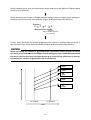
• Values in the speed table may vary slightly according to tire manufacturer and size.
• Select after referring to the value in the speed table.
6th
5th
4th
3rd
2nd
1st
GEAR
The number
of teeth
Engine speed (rpm)
16000
Tire radius (mm)
315 perimeter (m) 1.979
Primary reduction ratio 41 85
2.073
YZF-R6 Speed List
Speed
(km/h)
Engine Secondary
side
reduction
ratio
Wheel
(Sprocket)
side
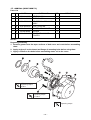
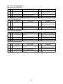
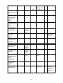
14. Mission Maintenance Set (2C0-A7000-70)
Parts List
No.
PART No.
PART NAME
*
21
90387-250R3
COLLAR
3
*
22
90209-21332
WASHER
6
*
23
93440-25186
CIRCLIP
10
*
24
90387-21003
COLLAR
3
*
25
90209-22352
WASHER
3
*
26
90209-21351
WASHER
3
*
27
90387-28011
COLLAR
3
*
28
90209-25011
WASHER
9
*
29
93440-28184
CIRCLIP
15
*
30
90387-25015
COLLAR
6
*
31
90214-25004
WASHER, CLAW
3
*
32
90214-25003
WASHER, CLAW
3
*
33
90387-21004
COLLAR
3
*
34
93102-35017
SEAL, OIL
3
*
35
93440-52014
CIRCLIP
5
*
36
90201-20278
WASHER, PLAIN
3
*
37
93306-20464
BRG.
3
*
38
93306-20464
BRG.
3
– 19 –
Q'TY
REMARKS
38
36
33
30
29
28
32
31
30
28
29
29
28
27
35
34
21
22
23
23
22
24
37
25
26
– 20 –
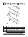
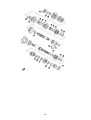
Transmission Assembly
The seal side should face outward (one side
seal bearing) and press in the bearing cup all
the way into the case until it touches bottom.
Apply molybdenum oil to inside of diameter.
After assembly, it should rotate smoothly.
Apply molybdenum oil to the inside diameter
and end. After assembly, it should rotate
smoothly.
Apply molybdenum oil to teeth of spline.
After assembly, it should slide smoothly.
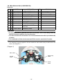
Points to be careful of the oil seal assembly
The convex part on the oil seal should be
put into the case groove vertically so that
the oil seal does not fall over and is tightly
fit into the bearing cup of the bearing.
(Apply grease to the lip.)
NOTE:
• Always use a new circlip.
• Do not mistake the washer and circlip directions.
(See drawing below.)
Matching mark
Matching mark
Washer
Circlip
Washer
Gear
Washer
Shaft
Edge
Portion R
Position the abutment joint of the circlip
right between the splines.
Shaft
Edge
Detail of installation of washer
Portion R
Rotate washer so that its teeth meet axlespline teeth on the axle, and then lock with
washer’s claw.
Assemble washer with putting together
their matching mark.
Detail of installation of circlip
Circlip
(Direction
not applicable)
Matching mark
Matching mark
Washer
Gear
Shaft
Washer
Washer
Position the abutment joint of the
circlip right between the splines.
Edge
Portion R
Shaft
Detail of installation of washer
Detail of installation of circlip
– 21 –
15. Drive Sprocket
Parts List
No.
PART No.
PART NAME
Q'TY
REMARKS
1
2C0-17460-74
SPROCKET, DRIVE
1
14T
2
2C0-17460-75
SPROCKET, DRIVE
1
15T
3
2C0-17460-76
SPROCKET, DRIVE
1
16T
These parts are for 520 chains (STD=525 chain).
Use the nuts for the kit to mount the drive sprocket.
These sprockets are manufactured to be compatible with new and old models.
GROOVE
MACHINING
STAMP OF THE NUMBER OF
TEETH ON BOTH SIDES
2CO ('06 and after YZF-R6)
5SL ('05 and previous YZF-R6)
Install with the grooved surface
facing outside of the chassis.
Install with the grooved surface
facing inside of the chassis.
CAUTION:
Take care not to install the sprocket in the wrong direction. If it is installed in the wrong
direction, it will cause the misalignment of the drive and rear sprockets, leading to the
loss of power.
– 22 –
16. Sprocket Nut Set (2C0-A7463-70)
Parts List
*
No.
PART No.
PART NAME
1
90179-20005
NUT, SPROCKET
1
2
90215-21256
WASHER, TONGUED
1
– 23 –
Q'TY
REMARKS
17. ACM Set (2C0-F1400-71)
Parts List
No.
PART No.
1
2C0-81410-70
STATOR ASSY.
1
2
2C0-81450-70
ROTOR ASSY.
1
*
3
2C0-15580-00
STARTER CLUTCH OUT.
ASSY.
1
*
4
2C0-15536-00
CLIP, STARTER
1
5
2C0-15411-71
COVER, CRANKCASE 1
1
6
90149-06080
SCREW
3
7
2C0-15451-70
GSKT., CRANKCASE
COVER 1
1
*
PART NAME
Q'TY
REMARKS
NOTE:
Regarding Assembly
1. Remove grease from the taper surfaces of both rotor and crank before assembling
them.
2. Apply engine oil on the thread and flange of mounting bolts before using them.
3. Apply Loctite® on the bolts before assembling stator coil to the cover.
STD
Tightening torque
70 N•m
Tightening torque
12.0 N•m
Tightening torque
– 24 –
18. Wire Harness Set (13S-F2590-70)
Parts List
No.
PART No.
PART NAME
Q'TY
REMARKS
1
13S-82590-70
WIRE HARNESS ASSY
1
°
2
5FL-83976-70
SWITCH ASSY.
1
MAIN SWITCH
*
3
5GF-83976-00
SW. HANDLE 1
1
PIT ROAD LIMITER
4
2C0-2128A-70
BRKT.,REGULATOR 1
1
5
2C0-82509-70
WIRE SUB-LEAD
1
6
4C8-82188-70
RESISTOR ASSY.
1
*
7
90480-13003
GROMMET
2
*
8
90560-06201
SPACER
2
*
9
90111-06051
BOLT, HEX. SOCKET
BUTTON
4
*
10
92907-06200
WASHER, PLAIN
1
CAUTION:
• Do not remove the AC generator but leave it to function. Use on the battery alone will
make the machine unable to run in a short time.
• The wire harness will not function if it is not assembled with the ECU (2C0-8591A-80)
of the kit.
• The combination of this wire harness and ECU cannot be used with 07 models.
• The switches (2 types) supplied in this set enable the main switch and pit road limiter to be
used. (See diagram 1.)
(Diagram 1)
Main switch
Engine stop
switch
Pit road
limiter
Starter
switch
– 25 –
• The switch installed to the STD machine may be used as is. (See diagram 2.)
• Map select switches Map 1 and Map 2 of the YMS “Comp. FUEL.”
CAUTION:
When switching to Map 1 or Map 2 using “Map Select” while riding, check that proper
riding is possible even when using either map.
(Diagram 2)
*Use 5FL-83976-70
SWITCH ASSY
supplied in this
package as a main
switch.
Pit road
limiter
ON OFF
Engine stop
switch
Not used
Map select
Lo → Map 1
Hi → Map 2
Pit road
limiter
ON ON
PUSH=OFF
Starter
switch
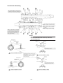
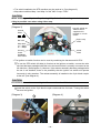
• The ignition cut switch function can be used by combining the harness and kit ECU.
1 To use the STD switch (left side) to function as the ignition cut switch, connect the wire
sub-lead that was packaged with this set to the terminal that is normally connected to the
left side horn. (See diagram 3.) However, if the resistor assembly that was packaged with
the set is not installed, there is the possibility that the ignition cut switch will operate
incorrectly in rainy weather. The resistor assembly is installed to the 2-pin black coupler
at the tail. (See diagram 4.)
CAUTION:
Do not bend the resistor assembly. It will cease to function if it is bent.
2 Install the switch to the 2-pin black coupler underneath the fuel tank. Turning the switch
ON cuts the ignition.
(Diagram 3)
5
(Diagram 4)
– 26 –
6
• If the kit’s large radiator is installed for the bracket regulator packaged with this set, use it
when the regulator is installed to the position shown in drawing 5.
(Diagram 5)
9
8
4
7
10
D
FW
FRAME
RECTIFIER
REGULATOR
• This harness has a coupler that connects to the 2D made data logger.
For details of the specifications of the data logger, please access the website.
Web http://www.2d-kit-system.com/
– 27 –
19. ECU Set (2C0-8591A-80)
Parts List
No.
PART No.
PART NAME
Q'TY
1
2C0-8591A-80
ECU
1
2
13S-2818Y-70
CD
1
REMARKS
YMS, MANUAL
• Use of this set and a wire harness included in the kit enables regulation (or setting) of fuel
injection and ignition timing, etc.
• For details as to how to regulate (or set) fuel injection and ignition timings, etc., refer to the
manual in the CD-ROM that comes with the set.
• There are two types of basic control data for the ECU included in this set: SS (Super
Sports) and ST (Stock Sports). They can be switched over and vice versa. To make it in the
ST specification, just remove two couplers located at the lower left of the kit harness fuel
tank. (See the figure below.)
<Setting-up Details>
SS specification: Kit cam shaft and *Recommended muffler
ST specification: *Recommended muffler
* Recommended muffler
Made by Akrapovic (For details of the specification, please access the website.)
Web http://www.akrapovic-exhaust.com
CAUTION:
• The ECU of this set will not function if it is not assembled with the wire harness (13S82590-70) of the kit.
• Do not use the ECU of this set for any other assembly than the one below.
ECU
WIRE HARNESS ASSY. THROTTLE BODY ASSY.
2006 Models
2C0-8591A-70
2C0-82590-70
2C0-13750-00
2007 Models
2C0-8591A-71
2C0-82590-80
2C0-13750-00
2008 Models
2C0-8591A-80
13S-82590-70
13S-13750-00
– 28 –
20. Cable Interface (13S-8533A-70)
Parts List
No.
PART No.
PART NAME
Q'TY
REMARKS
1
13S-8533A-70
CABLE, INTERFACE
1
USB
2
13S-N81CD-70
8cm CD
1
USB driver
• This cable connects the kit wire harness to the personal computer on which YEC FI
Matching System (YMS) is installed.
• Please see the YMS manual for instructions on how to use YMS.
• When connecting the cable to the PC for the first time, it is necessary to install the USB
driver. Refer to the USB Driver Installation Manual provided on the 8 cm CD for details on
how to install the USB driver.
• The product vendor ID and product ID are provided by the Hamamatsu TOA Electronics,
Inc.
Vendor ID: 6837
Product ID: 9001
– 29 –
• Use of the ECU in the kit and the harness allows functioning of the following codes in the
STD diagnosis.
* YMS-Monitor: YEC FI Matching System also allows functioning of the code shown below.
<Diagnosis Functions>
CODE
Contents
*YMS-Monitor
01
Throttle sensor
TPS 1(deg)
02
Atmospheric pressure sensor
Atmospheric (kPa)
03
Intake pressure sensor 1
Intake Air (kPa)
05
Intake temperature sensor
Air Temp. (°C)
06
Water temperature sensor
Water Temp. (°C)
07
Vehicle speed sensor
Speed Signal (--)
08
Overturn sensor
Lean Angle Signal
(V)
09
Monitor voltage
System Voltage (V)
13
Throttle sensor 2
TPS 2 (deg)
14
Accelerator sensor 1
APS 1 (deg)
15
Accelerator sensor 2
APS 2 (deg)
21
Neutral switch
Neutral SW
30
Ignition coil #1
—
31
Ignition coil #2
—
32
Ignition coil #3
—
33
Ignition coil #4
—
36
Injector (primary) #1
—
37
Injector (primary) #2
—
38
Injector (primary) #3
—
39
Injector (primary) #4
—
40
Injector (secondary) #1
—
41
Injector (secondary) #2
—
42
Injector (secondary) #3
—
43
Injector (secondary) #4
—
46
Intake funnel
—
50
Main relay
—
70
Program version
—
– 30 –
Self-Diagnosis Functions
• The ECU and harness in the kit provide the functions for the following codes of standard
self-diagnosis:
CODE
Description
00
All functions normally.
11
Cam angle sensor malfunctions.
12
Crank angle sensor malfunctions.
13
Intake pressure sensor malfunctions (open circuit / short circuit).
14
Intake pressure sensor malfunctions (piping system).
15
Throttle opening sensor malfunctions (open circuit / short circuit / ETV).
20
Intake pressure sensor or atmospheric pressure sensor malfunctions.
21
Water temperature sensor malfunctions (open circuit / short circuit).
22
Intake temperature sensor malfunctions (open circuit / short circuit).
23
Atmospheric pressure sensor malfunctions (open circuit / short circuit).
33
Ignition coil #1 malfunctions (open circuit).
34
Ignition coil #2 malfunctions (open circuit).
35
Ignition coil #3 malfunctions (open circuit).
36
Ignition coil #4 malfunctions (open circuit).
39
Injector (primary) malfunctions (open circuit).
40
Injector (secondary) malfunctions (open circuit).
43
Battery voltage monitor malfunctions (power source for fuel system).
46
Power source for vehicle malfunctions.
59
Accelerator opening sensor malfunctions (open circuit / short circuit).
60
Throttle motor malfunctions (drive system).
– 31 –
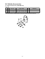
2-2 Vehicle Accessories
21. Engine Protector Set (2C0-A5491-70)
Parts List
No.
PART No.
PART NAME
Q'TY
1
2C0-15491-70
PROTECTOR
1
*
2
91314-06025
BOLT, HEX. SOCKET HEAD
2
*
3
91314-06020
BOLT, HEX. SOCKET HEAD
1
REMARKS
These parts protect the chassis as well as alleviating damage caused by overturning.
– 32 –
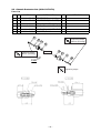
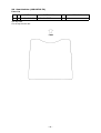
22. Chassis Protector Set (2C0-C117G-70)
Parts List
*
*
No.
PART No.
PART NAME
Q'TY
1
2C0-2117G-70
PROTECTOR(LH LONG)
1
2
2C0-2117G-90
PROTECTOR(RH SHORT)
1
3
2C0-21472-70
COLLAR, PROTECTOR
2
4
91317-10060
BOLT, HEX. SOCKET HEAD
1
5
91314-10065
BOLT, HEX. SOCKET HEAD
1
6
90201-10136
WASHER, PLAIN
2
REMARKS
Tightening torque
40 N•m (4.0 m•kg)
Tightening torque
40 N•m (4.0 m•kg)
ENGINE
FWD
Tightening torque
– 33 –
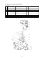
Before mounting the protector, cut the cowling so that the protector can fit against the chassis.
As a rough guide, cut by φ60 centered on the engine mount. See the figures below.
– 34 –
23. Oil Catch Tank Set (2C0-C1707-80)
Parts List
No.
PART No.
1
2C0-21707-70
OIL TANK COMP.
1
2
90450-25037
HOSE CLAMP ASSY.
3
3
13S-15373-70
PIPE, BREATHER
1
4
2C0-15393-70
PIPE, BREATHER 2
1
*
5
2C0-2419F-00
BRKT.
1
*
6
91317-06020
BOLT, HEX.SOCKET HEAD
2
*
7
90480-13018
GROMMET
2
*
8
90119-06044
BOLT, HEX. W/WASHER
2
*
PART NAME
This oil tank has the effective capacity of 540 cc.
– 35 –
Q'TY
REMARKS
24. Front Fork Spring Set
Parts List (13S-C3151-70)
*
No.
PART No.
PART NAME
Q'TY
1
13S-23141-70
SPRG., 1
2
2
13S-23142-00
SEAT, SPRING UPR.
2
3
13S-23118-70
SPACER
2
REMARKS
8.5 N/mm (0.87 kgf/mm)
Identification line (1 line)
Parts List (13S-C3151-75)
*
No.
PART No.
1
13S-23141-75
2
3
PART NAME
Q'TY
REMARKS
SPRG., 1
2
9.5 N/mm (0.97 kgf/mm)
Identification line (2 lines)
13S-23142-00
SEAT, SPRING UPR.
2
13S-23118-70
SPACER
2
Parts List (13S-C3151-80)
*
No.
PART No.
1
13S-23141-80
2
3
PART NAME
Q'TY
REMARKS
SPRG., 1
2
10.0 N/mm (1.02 kgf/mm)
Identification line (3 lines)
13S-23142-00
SEAT, SPRING UPR.
2
13S-23118-70
SPACER
2
Parts List (13S-C3151-85)
*
No.
PART No.
1
13S-23141-85
2
3
PART NAME
Q'TY
REMARKS
SPRG., 1
2
10.5 N/mm (1.07 kgf/mm)
Identification line (4 lines)
13S-23142-00
SEAT, SPRING UPR.
2
13S-23118-70
SPACER
2
– 36 –
Standard Setting (Standard front fork + Kit spring)
Specifications
Initial height of adjuster
9.5mm
Oil level
103mm
Suspension oil
Yamaha Suspension Oil 01
Click position
Stretching direction:
Make 20 notches backward from the fully stretched position
Pushing direction:
Low speed side: Make 15 notches backward from the fully
stretched position
High speed side: Make two turns back from the fully
stretched position
NOTE:
• Please build in the spacer and the spring seat of the attachment detaching the STD
spacer when the kit spring is set up.
• The spring rate is identified by the number of lines on its end.
STD
KIT
!
Replace
– 37 –
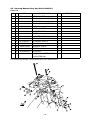
25. Steering Damper Stay Set (2C0-C3495-80)
Parts List
No.
PART No.
1
2C0-23495-80
STAY, DAMPER
1
2
91317-06025
BOLT, HEX. SOCKET HEAD
1
3
2C0-23488-80
SPACER
1
4
91317-08110
BOLT, HEX. SOCKET HEAD
1
5
95607-08100
NUT, U
1
6
2C0-2349T-80
BRKT., DAMPER
1
*
7
90201-07081
WASHER, PLAIN
2
*
8
90149-06302
SCREW
2
9
5VY-26398-00
WASHER, SPECIAL
1
10
91317-08025
BOLT, HEX. SOCKET HEAD
1
11
2C0-23439-71
STOPPER, STRG. 2
1
12
90387-06084
COLLAR
1
*
13
90201-07081
WASHER, PLAIN
1
*
14
90149-06302
SCREW
1
15
2C0-23429-70
STOPPER
1
16
90151-04002
SCREW, CROSSRECESSED
COUNTERSUNK
2
*
*
*
*
PART NAME
Q'TY
For the steering damper, use [OHLINS SD121 STROKE 68mm].
– 38 –
REMARKS
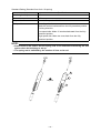
26. Seat Cushion (13S-24713-70)
Parts List
No.
PART No.
1
13S-24713-70
PART NAME
CUSHION SEAT
Anti slip seat.
Cut to any size for use.
– 39 –
Q’TY
1
REMARKS
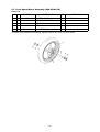
27. Front Spare Wheel Assembly (2C0-25100-70)
Parts List
No.
PART No.
PART NAME
Q'TY
*
1
5SL-25168-00
WHEEL, CAST
1
*
2
4XV-25117-00
SPACER, BEARING
1
*
3
93306-07208
BEARING
2
*
4
93106-28043
SEAL, OIL
2
*
5
93900-00030
VALVE, RIM
1
REMARKS
MAT BLACK
This part is an assembly of bearings, spacers and an air valve in a STD wheel.
– 40 –
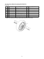
28. Rear Spare Wheel Assembly (2C0-25300-70)
Parts List
No.
PART No.
PART NAME
Q'TY
*
1
5SL-25338-00
WHEEL, CAST
1
*
2
93306-20531
BEARING
1
*
3
93106-40013
SEAL, OIL
1
*
4
93317-43580
BEARING
1
*
5
93420-61M07
CIRCLIP
1
*
6
4XV-25317-00
SPACER, BEARING
1
*
7
5SL-25383-00
COLLAR, WHEEL SHAFT
1
*
8
93900-00030
VALVE, RIM
1
REMARKS
MAT BLACK
This part is an assembly of bearings, spacers and an air valve in a STD wheel.
– 41 –
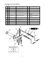
29. Throttle Set (2C0-C6300-70)
Parts List
No.
PART No.
PART NAME
Q'TY
REMARKS
°
1
2C0-26281-70
CAP, GRIP UPPER
1
*
2
5FL-26282-00
CAP, GRIP UNDER
1
°
3
5SL-26243-71
TUBE, GUIDE
1
°
4
2C0-26391-70
CLIP, WIRE 1
1
°
5
2C0-26311-70
WIRE, THROTTLE 1
2
Grip side: Retracting
sharing
°
6
2C0-26313-70
WIRE, THROTTLE 3
2
Engine side: Retracting
sharing
°
7
2C0-26261-70
CYLINDER
2
°
8
5FL-26244-70
SLIDER
2
9
2C0-2639E-70
PROTECTOR
2
*
10
90201-261L1
WASHER, PLAIN
1
*
11
91314-05020
BOLT, HEX. SOCKET HEAD
2
*
12
91314-05008
BOLT, HEX. SOCKET HEAD
1
12
4
5
10
7
8
9
6
3
1
2
11
Machining off the boss.
Scrape away CAP, GRIP UPPER
of the kit as shown above.
– 42 –
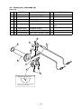
30. Throttle Set (13S-C6300-70)
Parts List
No.
PART No.
PART NAME
Q'TY
°
1
2C0-26281-70
CAP, GRIP UPPER
1
*
2
5FL-26282-00
CAP, GRIP UNDER
1
°
3
5SL-26243-71
TUBE, GUIDE
1
°
4
2C0-26391-70
CLIP, WIRE 1
1
°
5
13S-26302-70
THROTTLE WIRE ASSY.
2
*
6
90201-261L1
WASHER, PLAIN
1
*
7
91314-05020
BOLT, HEX. SOCKET HEAD
2
*
8
91314-05008
BOLT, HEX. SOCKET HEAD
1
&
"
#
$
!
%
Machining off the boss.
Scrape away CAP, GRIP UPPER
of the kit as shown above.
– 43 –
REMARKS
Common use for pulling
back.
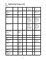
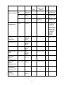
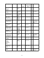
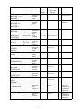
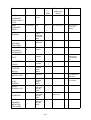
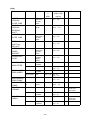
3 Tightening Torque List
Engine
To be tightened
Part No.
Part Name Screw dia.
x
pitch
Tightening
torque N•m
(kgf•m)
Q’ty
Remarks
CAP,
CAMSHAFT x
HEAD
90105-06027
BOLT,
FLANGE
M6 x 1.0
10.0±2 (1.0±0.2)
20
Embedded in
HEAD
95612-08625
BOLT,
STUD
M8 x 1.25
15.0±2 (1.5±0.2)
8
Tighten HEAD.
90179-10006
NUT
M10 x 1.25
TURN-OF-NUT
METHOD
AXIAL FORCE
41kN±2kN
SNUG TORQUE
28(2.8) +ROTATION ANGLE
55°
10
APPLY OIL
BOTH TO
THREAD AND
BEARING SURFACE. SEE
page 55 FOR
DETAILS.
Tighten HEAD.
90176-10075
NUT, CAP
M10 x 1.25
TURN-OF-NUT
METHOD
AXIAL FORCE
41kN±2kN
SNUG TORQUE
36(3.6) +ROTATION ANGLE
55°
2
APPLY OIL
BOTH TO
THREAD AND
BEARING SURFACE. SEE
page 55 FOR
DETAILS.
Tighten HEAD
on side of CAM
CHAIN
compartment.
90110-06094
BOLT,
HEXAGON
SOCKET
HEAD
M6 x 1.0
12.0±2 (1.2±0.2)
2
WITH WASHER
SPARK PLUG
5FL-9470070
PLUG,
SPARK
M10S x 1.0
10 – 12
(1.0 – 1.2)
4
SEE page 3 FOR
DETAILS.
HEAD COVER x
HEAD
90109-066F0
BOLT
M6 x 1.0
12.0±2 (1.2±0.2)
6
Plug for sand
drain hole
90340-18002
PLUG,
STRAIGHT
SCREW
M18 x 1.5
42±4 (4.3±0.4)
3
Check bolt for oil
passage
95022-08012
BOLT,
FLANGE,
SMALL
HEAD
M8 x 1.25
15.0±2 (1.5±0.2)
1
Tighten AI CAP.
90110-06175
BOLT HEXAGON
SOCKET
HEAD
M6 x 1.0
10.0±2 (1.0±0.2)
4
CAMSHAFT x
SPROCKET
90105-07004
BOLT,
FLANGE
M7 x 1.0
24.0±2 (2.4±0.2)
4
JOINT,
CARBURETOR
1 x HEAD
91312-06016
BOLT,
HEXAGON
SOCKET
HEAD
M6 x 1.0
10.0±2 (1.0±0.2)
8
– 44 –
CAM SHAFT
SHALL TURN
LIGHTLY.
APPLY LOCKING AGENT
(LOCKTITE®).
Q’ty
Remarks
M7 x 0.75
8
APPLY SUMICO
MORI ASSY OIL
150.
BOLT,
CON ROD
M7 x 0.75
8
APPLY SUMICO
MORI ASSY OIL
150.
90179-07001
NUT
M7 x 0.75
14.7±1.47
(1.5±0.15)
+180°±5°
8
APPLY SUMICO
MORI ASSY OIL
150.
ACM ROTOR x
CRANKSHAFT
90105126A8
BOLT,
FLANGE
M12 x 1.25
70±5 (7.0±0.5)
1
DEGREASE
TAPERED SURFACE. APPLY
OIL BOTH TO
BOLT BEARING
SURFACE AND
THREAD AND
TO BOTH SIDES
OF WASHER.
USE MORICOATED
WASHER.
TENSIONER
ASSY x
CYLINDER
90110-06106
BOLT,
HEXAGON
SOCKET
HEAD
M6 x 1.0
12.0±2 (1.2±0.2)
2
INSTALL TENSIONER ASSY.
Install COVER,
THERMOSTAT.
91312-06020
BOLT,
HEXAGON
SOCKET
HEAD
M6 x 1.0
12.0±2 (1.2±0.2)
2
Install JOINT.
90105-06082
BOLT,
FLANGE,
SMALL
HEAD
M6 x 1.0
10.0±2 (1.0±0.2)
2
Install WATER
PUMP.
90110-06140
BOLT,
HEXAGON
SOCKET
HEAD
M6 x 1.0
12.0±2 (1.2±0.2)
2
OIL PUMP
ASSY x
CRANKCASE 2
95812-06030
BOLT,
FLANGE
M6 x 1.0
12.0±2 (1.2±0.2)
2
OIL PUMP
ASSY x
CRANKCASE 2
95812-06080
BOLT,
FLANGE
M6 x 1.0
12.0±2 (1.2±0.2)
1
COVER,
STRAINER x
CRANKCASE 2
90109-06015
BOLT
M6 x 1.0
12.0±2 (1.2±0.2)
13
DRAIN BOLT for
COVER,
STRAINER
90340-14132
PLUG,
STRAIGHT
SCREW
M14 x 1.5
43.0±4 (4.3±0.4)
1
To be tightened
Part No.
Part Name Screw dia.
x
pitch
CON ROD X
CAP, CON ROD
2C0-1165400
BOLT,
CON ROD
2C0-1165A00
– 45 –
Tightening
torque N•m
(kgf•m)
DRAIN BOLT
To be tightened
Part No.
Part Name Screw dia.
x
pitch
Tightening
torque N•m
(kgf•m)
Q’ty
Tighten UNION
BOLT for
FILTER.
90401-20145
BOLT,
UNION
M20 x 1.5
70.0±5 (7.0±0.5)
1
ELEMENT, OIL
FILTER
5GH-1344020
OIL
CLEANER
ASSY
M20 x 1.5
17.0±2 (1.7±0.2)
1
HOLDER x
CRANKCASE 2
90110-06161
BOLT,
HEXAGON
SOCKET
HEAD
M6 x 1.0
12.0±2 (1.2±0.2)
2
PIPE, OIL x
CRANKCASE 2
90110-06161
BOLT,
HEXAGON
SOCKET
HEAD
M6 x 1.0
12.0±2 (1.2±0.2)
2
OIL COOLER x
CARNKCASE 2
5EB-1282200
BOLT,
UNION
M20 x 1.5
63.0±3 (6.3±0.3)
1
UPPER CASE x
CAP CASE
ASSY
92012-06020
BOLT,
BUTTON
HEAD
M6 x 1.0
5.0±0.5
(0.5±0.05)
4
UPPER CASE x
LOWER CASE
98902-05020
SCREW,
CROSS
RECESS
BINDING
M5 x 0.8
2.0±0.5
(0.2±0.05)
10
ELEMENT x
UPPER CASE
98902-05020
SCREW,
CROSS
RECESS
BINDING
M5 x 0.8
2.0±0.5
(0.2±0.05)
1
JOINT,
CARBURETOR
1 x THROTTLE
90450-56007
HOSE
CLAMP
ASSY
M5 x 0.8
2.0 – 2.5
(0.2 – 0.25)
4
THROTTLE x
FUNNEL
90109-05011
BOLT
M5 x 0.8
3.4 – 5
(0.34 – 0.5)
6
LOWER FILTER
CASE x
FUNNEL
(SUPPORT
UNIT)
90159-05035
SCREW,
WITH
WASHER
M5 x 0.8
2.5±0.5
(0.25±0.05)
2
Install
THROTTLE
WIRE
13S-2630200
THROTTLE WIRE
ASSY.
M6 x 1.0
3.5 – 5.5
(0.35 – 0.55)
2
NUT, RING x
HEAD
90179-08410
NUT
M8 x 1.25
20.0±2 (2.0±0.2)
8
– 46 –
Remarks
APPLY GREASE
TO O-RING.
APPLY OIL TO
THREAD AND
BEARING SURFACE.
CONTACT-FIT
COLLAR OR
TORQUE CONTROL
TIGHTEN
EXHAUST PIPE
& HEAD.
Tightening
torque N•m
(kgf•m)
Q’ty
Remarks
M8 x 1.25
20.0±2 (2.0±0.2)
2
INSTALL
EXHAUST PIPE.
BOLT,
FLANGE
(SMALL
HEAD)
M8 x 1.25
34.0±4 (3.4±0.4)
1
INSTALL
DAMPER.
91314-06030
BOLT,
HEXAGON
SOCKET
HEAD
M6 x 1.0
10.0±2 (1.0±0.2)
1
SILENCER x
FOOT REST
90105-08063
BOLT,
FLANGE
M8 x 1.25
20.0±2 (2.0±0.2)
1
Install WIRE
PULLEY.
13S-1133E00
13S-1133F00
WIRE,
PULLEY, 1
WIRE,
PULLEY, 2
M6 x 1.0
5 – 7 (0.5 – 0.7)
1
PULLEY x
GEARED
MOTOR
90110-05028
BOLT,
HEXAGON
SOCKET
HEAD
M5 x 0.8
6.5±1.5
(0.65±0.15)
1
BRACKET 7 x
FRAME
95827-06014
BOLT,
FLANGE
(SMALL
HEAD)
M6 x 1.0
6 – 10 (0.6 – 1.0)
2
BRACKET 7 x
SERVOMOTOR
95027-06025
BOLT,
FLANGE
(SMALL
HEAD)
M6 x 1.0
5 – 8 (0.5 – 0.8)
2
Install
MUFFLER
PROTECTOR.
90111-06071
BOLT,
HEXAGON
SOCKET
BUTTON
M6 x 1.0
8.0±1.5
(0.8±0.15)
1
Install
MUFFLER
PROTECTOR.
90111-06099
BOLT,
HEXAGON
SOCKET
BUTTON
M6 x 1.0
6.5±1.5
(0.65±0.15)
2
EXHAUST
VALVE
SUBASSY
90179-06063
NUT
M6 x 1.0
6.5±1.5
(0.65±0.15)
1
CRANKCASE 1
x CRANKCASE
2
90119-08083
BOLT,
HEXAGON
WITH
WASHER
M8 x 1.25
See page 56 for
details.
8
APPLY OIL
BOTH TO
THREAD AND
TO BEARING
SURFACE.
CRANKCASE 1
x CRANKCASE
2
90119-08084
BOLT,
HEXAGON
WITH
WASHER
M8 x 1.25
See page 56 for
details.
2
APPLY OIL
BOTH TO
THREAD AND
TO BEARING
SURFACE.
To be tightened
Part No.
Part Name Screw dia.
x
pitch
STAY,
MUFFLER 1, 2 x
MUFFLER
91314-08035
BOLT,
HEXAGON
SOCKET
HEAD
STAY,
MUFFLER 2 x
BRACKET,
MUFFLER 1
90105-08054
Tighten BAND,
MUFFLER.
1
– 47 –
Tightening
torque N•m
(kgf•m)
Q’ty
M6 x 1.0
10.0±2 (1.0±0.2)
2
APPLY OIL
BOTH TO
THREAD AND
TO BEARING
SURFACE.
BOLT,
FLANGE
M6 x 1.0
10.0±2 (1.0±0.2)
7
APPLY OIL
BOTH TO
THREAD AND
TO BEARING
SURFACE.
95812-08065
BOLT,
FLANGE
M8 x 1.25
24±2 (2.4±0.2)
2
APPLY OIL
BOTH TO
THREAD AND
TO BEARING
SURFACE.
CRANKCASE 1
x CRANKCASE
2
95812-06065
BOLT,
FLANGE
M6 x 1.0
10.0±2 (1.0±0.2)
3
APPLY OIL
BOTH TO
THREAD AND
TO BEARING
SURFACE.
CRANKCASE 1
x CRANKCASE
2
95812-06045
BOLT,
FLANGE
M6 x 1.0
10.0±2 (1.0±0.2)
3
APPLY OIL
BOTH TO
THREAD AND
TO BEARING
SURFACE.
CRANKCASE 1
x CRANKCASE
2
95812-06030
BOLT,
FLANGE
M6 x 1.0
10.0±2 (1.0±0.2)
1
APPLY OIL
BOTH TO
THREAD AND
TO BEARING
SURFACE.
Install COVER,
CRANKCASE 1.
90109-06015
BOLT
M6 x 1.0
12.0±2 (1.2±0.2)
9
Install COVER,
CRANKCASE 2.
90109-06031
BOLT
M6 x 1.0
12.0±2 (1.2±0.2)
7
Install COVER,
CRANKCASE 2.
90110-06156
BOLT,
HEXAGON
SOCKET
HEAD
M6 x 1.0
12.0±2 (1.2±0.2)
2
Install COVER
1.
90110-06303
BOLT,
HEXAGON
SOCKET
HEAD
M6 x 1.0
12.0±2 (1.2±0.2)
5
COVER 1 x
HOLDER,
CLUTCH
90109-06015
BOLT
M6 x 1.0
12.0±2 (1.2±0.2)
2
COVER 1 x
BOLT
92014-08014
BOLT,
BUTTON
HEAD
M8 x 1.25
15.0±2 (1.5±0.2)
1
COVER 1 x
PLUG,
STRAIGHT
90340-32004
PLUG,
STRAIGHT
SCREW
M32 x 1.5
CLOSE CONTACT WITH
BEARING SURFACE
1
To be tightened
Part No.
Part Name Screw dia.
x
pitch
CRANKCASE 1
x CRANKCASE
2
90109-06100
BOLT
CRANKCASE 1
x CRANKCASE
2
95812-06055
CRANKCASE 1
x CRANKCASE
2
– 48 –
Remarks
Tightening
torque N•m
(kgf•m)
Q’ty
M6 x 1.0
12.0±2 (1.2±0.2)
3
SCREW
M6 x 1.0
10.0±2 (1.0±0.2)
3
90149-06082
SCREW
M6 x 1.0
12.0±2 (1.2±0.2)
1
Install COVER,
CHAIN CASE.
90110-06060
BOLT,
HEXAGON
SOCKET
HEAD
M6 x 1.0
10.0±2 (1.0±0.2)
3
Install M
GALLERY
PLUG.
36Y-1518900
PLUG
M16 x 1.5
8.0±2 (0.8±0.2)
2
TAKE CARE
NOT TO OVERTIGHTEN
COVER,
CRANKCASE 1
x CLAMP
90149-06082
SCREW
M6 x 1.0
10.0±2 (1.0±0.2)
1
STATOR LEAD
Install COVER.
90109-06015
BOLT
M6 x 1.0
12.0±2 (1.2±0.2)
5
Install OIL PIPE
(OUTSIDE)
90110-06161
BOLT,
HEXAGON
SOCKET
HEAD
M6 x 1.0
12.0±2 (1.2±0.2)
2
CRANKCASE 2
x PICKUP
90110-06168
BOLT,
HEXAGON
SOCKET
HEAD
M6 x 1.0
10.0±2 (1.0±0.2)
2
Embedded in
CRANKCASE x
STUD,
EMBEDDED
90116-1002*
BOLT,
STUD
M10 x 1.25
(HEIGHT
68.2±1)
10
Install
PRESSURE
PLATE.
90159-06024
SCREW,
W/W
M6 x 1.0
8.0±2 (0.8±0.2)
6
BOSS, CLUTCH
x MAIN AXLE
4B1-1637770
NUT, LOCK
M20 x 1.0
115.0±5
(11.5±0.5)
1
To be tightened
Part No.
Part Name Screw dia.
x
pitch
PLATE,
BREATHER x C/
C1
90149-06082
SCREW
COVER,
CRANKCASE 1
x STATOR
ASSY
90149-06080
PLUG WITH
COMMUNICATION
HOLE x
CRANKCASE 1
– 49 –
Remarks
CRIMP AND
APPLY OIL
BOTH TO
THREAD AND
BEARING SURFACE.
Tightening
torque N•m
(kgf•m)
Q’ty
M8 x 1.25
25.0±2 (2.5±0.2)
6
NUT
M20 x 1.0
85.0±5 (8.5±0.5)
1
NO OIL SHALL
BE STUCK.
CRIMP.
90151-06024
SCREW,
CROSSRECESSED
COUNTERSUNK
M6 x 1.0
12.0±2 (1.2±0.2)
3
CRIMP.
Install
STOPPER,
SHAFT BAR.
90110-06182
BOLT,
HEXAGON
M6 x 1.0
10.0±2 (1.0±0.2)
2
STOPPER
embedded in
CRANKCASE
1D7-1812700
STOPPER,
SCREW
M8 x 1.25
22.0±2 (2.2±0.2)
1
Install ARM,
SHIFT.
95822-06020
BOLT,
FLANGE
M6 x 1.0
10.0±2 (1.0±0.2)
1
Install ROTOR,
PICKUP.
90105-08113
BOLT,
FLANGE
M8 x 1.25
35.0±5 (3.5±0.5)
1
Install
STARTER
MOTOR.
90105-06083
BOLT,
FLANGE
(SMALL
HEAD)
M6 x 1.0
10.0±2 (1.0±0.2)
2
NEUTRAL
SWITCH ASSY
3GB-8254001
NEUTRAL
S/W ASSY
M10 x 1.25
19.6±2 (2.0±0.2)
1
OVERTIGHTENING LEADS TO
DAMAGE.
Install OIL
LEVEL
SENSOR.
95022-06016
BOLT,
FLANGE
(SMALL
HEAD)
M6 x 1.0
10.0±2 (1.0±0.2)
2
APPLY GREASE
TO O-RING.
SPEED
SENSOR x C/C
91312-06016
BOLT,
HEXAGON
SOCKET
HEAD
M6 x 1.0
10.0±2 (1.0±0.2)
1
CAM SENSOR x
COVER H/C
90110-06175
BOLT,
HEXAGON
SOCKET
HEAD
M6 x 1.0
7.5±1.5
(0.75±0.15)
1
WIRE
HARNESS
(NEGATIVE
LEAD WIRE)
91380-06012
BOLT,
HEXAGON
SOCKET
HEAD
M6 x 1.0
10.0±2 (1.0±0.2)
1
To be tightened
Part No.
Part Name Screw dia.
x
pitch
BOSS,
PRESSURE
PLATE x BOLT,
STUD
2C0-1637400
BOLT,
STUD
Install
SPROCKET,
DRIVE.
90179-20005
HOUSING,
BEARING
– 50 –
Remarks
CHECK FOR
SERRATION
TIGHTENING
UP.
To be tightened
Part No.
Part Name Screw dia.
x
pitch
Tightening
torque N•m
(kgf•m)
Q’ty
Install O2
SENSOR.
13S-8592A00
O2 SENSOR
M18 x 1.5
45.0±5 (4.5±0.5)
1
Install
THERMOSENSOR.
8CC-8579001
THERMOSENSOR
ASSY
M12 x 1.5
17.6±2 (1.8±0.2)
1
– 51 –
Remarks
Body
To be tightened
Part No.
Part Name Screw dia.
x
pitch
Tightening
torque N•m
(kgf•m)
Q’ty
HANDLE,
CROWN &
OUTER TUBE
91314-08030
BOLT,
HEXAGON
SOCKET
HEAD
M8 x 1.25
23 – 28
(2.3 – 2.8)
2
HANDLE,
CROWN &
STEERING
SHAFT
90170-28419
NUT, HEXAGON
M28 x 1.0
100 – 125
(10.2 – 12.7)
1
HANDLE &
OUTER TUBE
91314-08030
BOLT,
HEXAGON
SOCKET
HEAD
M8 x 1.25
28 – 35
(2.8 – 3.6)
2
STEERING
SHAFT and
RING NUT
90179-30691
NUT
M30 x 1.0
12 – 15
(1.2 – 1.5)
1
OUTER TUBE &
UNDER
BRACKET
91314-08030
BOLT,
HEXAGON
SOCKET
HEAD
M8 x 1.25
20 – 25
(2.0 – 2.5)
4
E/G BRACKET,
FRONT
95024-10040
BOLT,
FLANGE
(SMALL
HEAD)
M10 x 1.25
35 – 45
(3.6 – 4.6)
2
E/G BRACKET,
REAR UPPER
90105-12228
BOLT,
FLANGE
M12 x 1.25
90179-12248
NUT
M12 x 1.25
90105-12228
BOLT,
FLANGE
M12 x 1.25
90179-12248
NUT
M12 x 1.25
58 – 70
(5.9 – 7.1)
1
MAIN FRAME &
REAR FRAME
90149-10002
SCREW
M10 x 1.25
33 – 40
(3.3 – 4.1)
4
PIVOT SHAFT &
FRAME
2C0-2214110
SHAFT,
PIVOT
M32 x 1.5
12 – 19
(12.2 – 1.9)
1
ARM, RELAY 1
& FRAME
90109-10017
BOLT
M10 x 1.25
95602-10200
NUT, U
FLANGE
M10 x 1.25
90109-12010
BOLT
M12 x 1.25
90185-12119
NUT, SELF
LOCKING
M12 x 1.25
E/G BRACKET,
REAR UNDER
ARM, RELAY 1
& ARM 1
– 52 –
Remarks
1
58 – 70
(5.9 – 7.1)
1
1
1
31 – 49
(3.2 – 5)
1
1
31 – 49
(3.2 – 5)
SCREW IN
FROM THE
LEFT SIDE
1
SCREW IN
FROM THE
LEFT SIDE
Part Name Screw dia.
x
pitch
Tightening
torque N•m
(kgf•m)
Q’ty
Remarks
To be tightened
Part No.
ARM 1 & REAR
ARM
90109-12010
BOLT
M12 x 1.25
90185-12119
NUT, SELF
LOCKING
M12 x 1.25
REAR
CUSHION &
ARM, RELAY 1
90109-12011
BOLT
M12 x 1.25
90185-12119
NUT, SELF
LOCKING
M12 x 1.25
31 – 49
(3.2 – 5)
1
CHAIN PULLER
ADJUST NUT
95604-08200
NUT, U
FLANGE
M8 x 1.25
12 – 19
(12.2 – 1.9)
2
SHAFT, PIVOT
& LOCK NUT
2C0-2225200
NUT 2
M32 x 1.5
75 – 115
(7.6 – 11.7)
1
SHAFT, PIVOT
& U NUT
90185-22002
NUT SELF
LOCKING
M22 x 1.5
55 – 85
(5.6 – 8.7)
1
FUEL PUMP &
FUEL TANK
90110-05028
BOLT,
HEXAGON
SOCKET
HEAD
M5 x 0.8
3–5
(0.3 – 0.5)
6
FRONT STAY
for FUEL TANK
& FRAME
90110-06233
BOLT,
HEXAGON
SOCKET
HEAD
M6 x 1.0
5–8
(0.5 – 0.8)
1
Mid portion of
FUEL TANK &
STAY
91312-06016
BOLT,
HEXAGON
SOCKET
HEAD
M6 x 1.0
7 – 10
(0.7 – 1.0)
2
BRACKET,
TANK (rear) &
FUEL TANK
91312-06090
BOLT,
HEXAGON
SOCKET
HEAD
M6 x 1.0
5–8
(0.5 – 0.8)
1
BRACKET,
TANK (rear) &
REAR FRAME
90111-06071
BOLT,
HEXAGON
SOCKET
BUTTON
M6 x 1.0
5–8
(0.5 – 0.8)
4
FRONT WHEEL
SHAFT & FR
FORK
90105-14002
BOLT,
FLANGE
M14 x 1.5
REAR WHEEL
SHAFT & NUT
90185-24007
NUT, SELF
LOCKING
M24 x 1.5
90 – 130
(9.2 – 13.3)
1
FR CALIPER &
FR FORK
90401-10012
BOLT,
UNION
M10 x 1.25
30 – 40
(3.1 – 4.1)
4
DISC BRAKE &
FR WHEEL
90149-06043
SCREW
M6 x 1.0
14 – 22
(1.4 – 2.2)
10
APPLY LOCKING AGENT
(LOCKTITE®).
DISC BRAKE &
RR WHEEL
90149-08009
SCREW
M8 x 1.25
23 – 37
(2.3 – 3.8)
5
APPLY LOCKING AGENT
(LOCKTITE®).
– 53 –
1
31 – 49
(3.2 – 5)
SCREW IN
FROM THE
LEFT SIDE
1
1
SCREW IN
FROM THE
LEFT SIDE
1
To be tightened
Part No.
Part Name Screw dia.
x
pitch
Tightening
torque N•m
(kgf•m)
Q’ty
REAR WHEEL
SPROCKET &
CLUTCH HUB
90185-10009
NUT, SELF
LOCKING
M10 x 1.25
90 – 109
(9.2 – 11.1)
6
SPLIT BOLT for
FRONT AXLE
91314-08040
BOLT,
HEXAGON
SOCKET
HEAD
M8 x 1.25
18 – 23
(1.8 – 2.3)
4
– 54 –
Remarks
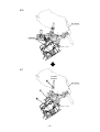
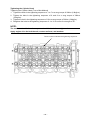
Tightening the Cylinder Head
Tightening the Cylinder Head (Turn-of-Nut Method)
1. Tighten the bolts in the tightening sequence of 1 to 7 to a snug torque of 28N•m (2.8kgf•m).
2. Tighten the bolts in the tightening sequence of 8 and 9 to a snug torque of 36N•m
(3.6kgf•m).
3. Tighten the bolt in the tightening sequence of 10 to a snug torque of 28N•m (2.8kgf•m).
4. Retighten the bolts in the tightening sequence of 1 to 10 to a turn-of-nut angle of 55°.
NOTE:
The numbers 1 to 10 show the sequence in which the bolts are tightened.
Apply engine oil to the bolt threads, contact surfaces, and washers.
These numbers indicate the tightening sequence.
– 55 –
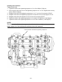
Installing the Crankcase
Tightening the bolts
1. Tighten the bolts in the tightening sequence of 1 to 10 to 20N•m (2.0kg•m).
2. After loosening the bolts once in the tightening sequence of 1 to 10, retighten them one by
one to 12N•m (1.2kg•m).
3. Retighten the bolts in the tightening sequence of 1 to 7 to a turn-of-nut angle of 50°±5°.
4. Retighten the bolts in the tightening sequence of 8 and 9 to a turn-of-nut angle of 75°±5°.
5. Retighten the bolt in the sequence of 10 to a turn-of-nut angle of 50°±5°.
6. Tighten the bolts in the tightening sequence of 11 and 12 to 24±2N•m (2.4±0.2kgf•m).
7. Tighten the bolts in the tightening sequence of 13 to 29 to 10±2N•m (1.0±0.2kgf•m).
NOTE:
The numbers 1 to 29 show the sequence in which the bolts are tightened.
Apply engine oil to the bolt threads and both sides of the washers.
These numbers indicate the tightening sequence.
– 56 –
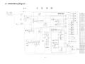
4 YZF-R6 Wiring Diagram
– 57 –
Published by YAMAHA MOTOR ENGINEERING co., LTD