1
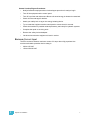
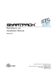
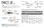
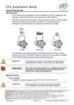
ERn Wall Mount Enclosure Installation Manual Revision B C o p y r i g h t © E le c tr o n i c T h e a t r e C o n t r o l s , I n c . All Rights reserved. P r o d u c t in f o r m a t i on a n d s p e c i f i c a t i o n s s u bj e c t t o c h a n g e . P a r t N u m b e r : 7180M2100 R e v B R e le a s ed : 2 0 1 2 - 1 0 ET C ®, U n i s o n ®, E D M X ™ a r e e it h e r r e g i s t e r e d t ra d e m a r k s o r t r a d e m a r k s o f E l e c t r o n i c T h e a t r e C o n t r o l s , I n c . in t h e U n i te d S t a te s a n d o t h e r c o u n t r ie s . E c h e l o n ®, LO N ®, L ONW ORKS® a r e r e g i s t e r e d tr a d e m a r k s o f E c h e l on C or p o r a ti o n i n t h e U n i t ed S t a t es a n d other countries. A l l o t h e r t r a d em a r k s , b o t h m a r k e d a n d n o t m a r k e d , a r e th e p r o p e r t y o f t h e i r r e s p e c t i v e o w n e r s . Table of Contents Introduction . . . . . . . . . . . . . . . . . . . . . . . . . . 1 ERn External Processing Rack . . . . . . . . . . . . . . . . . . . . . . . . . .1 ERn Modules and Options. . . . . . . . . . . . . . . . . . . . . . . . . . . . . .2 Warnings and Notice Conventions . . . . . . . . . . . . . . . . . . . . . . .4 Contacting ETC . . . . . . . . . . . . . . . . . . . . . . . . . . . . . . . . . . . . . .4 Prepare for Installation . . . . . . . . . . . . . . . . . 5 Preparations . . . . . . . . . . . . . . . . . . . . . . . . . . . . . . . . . . . . . . . . . . . .6 Unpack and Inspect . . . . . . . . . . . . . . . . . . . . . . . . . . . . . . . . . . .6 Main Circuit Breaker Protection . . . . . . . . . . . . . . . . . . . . . . . . . .6 Lockout / Tagout . . . . . . . . . . . . . . . . . . . . . . . . . . . . . . . . . . .6 General Lockout/Tagout Procedures: . . . . . . . . . . . . . . . . . . . .7 Maximum Current Input . . . . . . . . . . . . . . . . . . . . . . . . . . . . . . . .7 Where to Install the Enclosure . . . . . . . . . . . . . . . . . . . . . . . . . . . . . .8 Clearance Requirements . . . . . . . . . . . . . . . . . . . . . . . . . . . . . . .8 Rack Dimensions and Weights . . . . . . . . . . . . . . . . . . . . . . . . . .8 Installation Environment Requirements . . . . . . . . . . . . . . . . . . . .8 Wire Requirements. . . . . . . . . . . . . . . . . . . . . . . . . . . . . . . . . . . . . . .9 Wire Routing and Specification . . . . . . . . . . . . . . . . . . . . . . . . . .9 Control Specifications . . . . . . . . . . . . . . . . . . . . . . . . . . . . . . . . .9 Data Types and Topologies . . . . . . . . . . . . . . . . . . . . . . . . .10 DMX (Digital Multiplex) . . . . . . . . . . . . . . . . . . . . . . . . . . . . . .10 Auxiliary 24 Vdc . . . . . . . . . . . . . . . . . . . . . . . . . . . . . . . . . . .10 Install Rack Enclosures. . . . . . . . . . . . . . . . 11 Install the Rack Enclosure . . . . . . . . . . . . . . . . . . . . . . . . . . . . . . . .12 Rough-in Conduit and Wiring . . . . . . . . . . . . . . . . . . . . . . . . . . . . . .13 Remove Option Modules . . . . . . . . . . . . . . . . . . . . . . . . . . . . . .13 Rough-in Line and Control Conduit and Wiring . . . . . . . . . . . . .14 Terminate Wiring. . . . . . . . . . . . . . . . . . . . . 15 Connect Line Power Wiring . . . . . . . . . . . . . . . . . . . . . . . . . . . . . . .16 Connect Control Wiring . . . . . . . . . . . . . . . . . . . . . . . . . . . . . . . . . .17 Connect ERn Right I/O Data Terminations . . . . . . . . . . . . . . . .18 Terminate DMX Control Wiring . . . . . . . . . . . . . . . . . . . . . . .18 DMX Input Termination: Screw Terminals Connector. . . . . . .18 DMX Input/Output Termination: Insulation Displacement Connectors . . . . . . . . . . . . . . . . . . . . . . . . . . . . . . . . . . . . . . . . . .19 Terminate LinkConnect Control Wiring . . . . . . . . . . . . . . . . .19 Terminate Auxiliary Power . . . . . . . . . . . . . . . . . . . . . . . . . .20 DMX Termination . . . . . . . . . . . . . . . . . . . . . . . . . . . . . . . . .21 Connect ERn Left I/O Data Terminations . . . . . . . . . . . . . . . . .21 Connect to Serial RS-232 . . . . . . . . . . . . . . . . . . . . . . . . . . .21 Connect to Ethernet RJ-45 . . . . . . . . . . . . . . . . . . . . . . . . . .22 Connect to Contact Inputs and Contact Outputs . . . . . . . . .22 Terminate Contact Inputs . . . . . . . . . . . . . . . . . . . . . . . . . . . .22 Table of Contents i Terminate Contact Outputs . . . . . . . . . . . . . . . . . . . . . . . . . . .22 Final Installation and Power Up . . . . . . . . . 23 Completing the Installation . . . . . . . . . . . . . . . . . . . . . . . . . . . . . . . .24 Check Main Power Wiring . . . . . . . . . . . . . . . . . . . . . . . . . . . . .24 Check Line Voltages . . . . . . . . . . . . . . . . . . . . . . . . . . . . . . . . .24 Final Installation. . . . . . . . . . . . . . . . . . . . . . . . . . . . . . . . . . . . .25 Install Rack Options . . . . . . . . . . . . . . . . . . 26 Rack Options . . . . . . . . . . . . . . . . . . . . . . . . . . . . . . . . . . . . . . . . . .27 Install the RideThru Option (URTO) Kit . . . . . . . . . . . . . . . . . . .27 Connect RideThru Option Wiring . . . . . . . . . . . . . . . . . . . . .28 Install the BatteryPack Option (UBPO) Kit. . . . . . . . . . . . . . . . .29 Install a Paradigm Repeater or Dual Repeater Module . . . . . . .31 Terminate LinkConnect Control Wiring . . . . . . . . . . . . . . . . .32 Terminate Auxiliary Power . . . . . . . . . . . . . . . . . . . . . . . . . .33 Status Indicators . . . . . . . . . . . . . . . . . . . . . . . . . . . . . . . . . .34 Install Redundant Power Supply . . . . . . . . . . . . . . . . . . . . . . . .35 Status Indicator . . . . . . . . . . . . . . . . . . . . . . . . . . . . . . . . . . . . . . . .35 Install the Ethernet Switch Module . . . . . . . . . . . . . . . . . . . . . .36 Connect CAT5e Wiring . . . . . . . . . . . . . . . . . . . . . . . . . . . . .37 Status Indicators. . . . . . . . . . . . . . . . . . . . . . . . . . . . . . . . . . . . . . . .38 ii Unison® ERn Wall Mount Enclosure Installation Manual Introduction Welcome to the installation manual for the Unison® ERn Enclosure. This manual contains the procedures for safe and efficient installation of wall-mount ERn series control enclosures, including wire termination and option kit installation. ERn series enclosures provide Unison architectural control to distributed Unison, Sensor+, or other DMX512 systems. Used stand alone or in multi-processor network systems, the Wall Mount ERn series offers elegant low-profile surface mounting, modular back-lit control electronics, and the ultimate in architectural lighting control versatility. The ERn enclosure is available in two sizes, ERn2 (single processor) and ERn4 (dual processor), The ERn is available in three single phase voltage options, 100-120, 230 CE, and 240 VAC to meet your installation requirements. Wall Mount ERn External Processing Rack Model Voltage / Frequency Notes ERn2-W-120 ERn2-W-230CE 85-120 VAC, 47-63 Hz (single phase) 180-265 VAC, 47-63Hz (single phase) ERn2-W-240 180-265 VAC, 47-63 Hz (single phase) ERn4-W-120 ERn4-W-230CE 85-120 VAC, 47-63 Hz (single phase) 180-265 VAC, 47-63Hz (single phase) ERn4-W-240 180-265 VAC, 47-63 Hz (single phase) External processing rack configured for wall mounting. Use with one Paradigm Architectural Control Processor (ACP) and one option module. External processing rack configured for wall mounting. Use with up to two Paradigm Architectural Control Processors (ACP) and up to two option modules. The ERn2 enclosure supports a single Paradigm Architectural Control Processor (P-ACP) and one Paradigm Station Power Module (P-SPM) or a blank module (ERn-BM). The accessory tray in the bottom of the enclosure can be used for an additional accessory option including a 5-port Ethernet Switch (ERn-NET) or a Redundant Rack Power Supply (ERn-RPS). The ERn4 enclosure supports up to two Paradigm Architectural Control Processors (PACP) and two Paradigm Station Power Modules (P-SPM) or a Paradigm Repeater Module (P-REP). Alternatively, the top two slots in the enclosure may be used for a Paradigm Dual Repeater Module (P-DREP). The accessory tray in the bottom of the enclosure can be used for an additional accessory option including a 5-port Ethernet Switch (ERn-NET) or a Redundant Rack Power Supply (ERn-RPS). Introduction 1 ERn Modules and Options P-ACP URTO P-SPM UBPO P-REP ERn-RPS ERn-NET P-DREP ERn-BM Model Part Number P-ACP 7180A1001 P-SPM 7182A1001 P-REP 7182A1003 P-DREP 7182A1004 2 Description Notes Paradigm Architectural The Paradigm ACP provides powerful and flexible control for Control Processor architectural and theatrical applications with integrated networking for both NetConnect and LinkConnect networks. • Supports up to 1024 control channels using industry standard protocols. • User interface remains accessible with the enclosure door closed. • Supports up to 62 Unison control stations over the LinkConnect network with the use of Paradigm Station Power and Repeater Modules. • Supports up to 12 Paradigm Touchscreen Stations using LinkConnect or NetConnect protocols. • Provides two ports of one DMX universe each (512 addresses each), individually switchable between input and output. Paradigm Station The Paradigm Station Power Module (P-SPM) provides power for Power Module Unison control stations over the LinkConnect network and supports the station data bus length up to 1,640 feet (500m). • Supports up to 32 Unison control stations over LinkConnect. Paradigm Station The Paradigm Station Repeater (P-REP) module extends the Repeater Module system station bus length by 1,640 feet (500m) and increases the possible station count by an additional 30 stations. For use only in an ERn4 enclosure. • For use in an ERn4 enclosure only. • Supports up to 30 additional Unison control stations over LinkConnect. Paradigm Dual Station The Paradigm Dual Station Repeater (P-DREP) module extends Repeater Module the system station bus length by 3,280 feet (1,000m) through two separate topology-free segments, each supporting 1,640 feet (500m). • The dual repeater supports up to 30 additional Unison control stations. • For use in an ERn4 enclosure only. Unison® ERn Wall Mount Enclosure Installation Manual Part Number Model ERn-NET 7180A1400 UBPO 7180A1411 URTO 7180A1410 ERn-BM 7180A1402 ERn-RPS 7180A1401 Introduction Description Notes ERn Ethernet Switch Module The ERn Ethernet Switch (ERn-NET) provides four ports of 802.3af compliant Power over Ethernet (PoE) and one port for the Paradigm Architectural Control Processor. • Not compatible with a rack mounted ERn enclosures. • Not compatible with an ERn4 230 VAC enclosures. Unison Battery Pack The BatteryPack Option (UBPO) provides back-up power during Option Kit power outages for the Paradigm Architectural Control Processor for up to 90 minutes for an ERn enclosure with one P-ACP or up to 45 minutes for an ERn4 with two P-ACPs installed. • Not compatible with rack mounted ERn enclosures. Unison Ride Thru The Unison Ride Through Option (URTO) kit provides power for Option Kit one Paradigm Architectural Control Processor in the host enclosure for a limited time (minimum of 12 seconds) during brief power outages or drop outs. • If installed in an ERn4 enclosure, one URTO is required per installed Paradigm ACP. Airflow Option Module Required for any empty module space in the ERn enclosure. • Installs into the accessory option module slot of an ERn enclosure. ERn Redundant Power The ERn Redundant Power Supply (ERn-RPS) provides an Supply additional rack power Supply that powers the ERn enclosure if the primary rack power supply is removed or fails. • Tool-free installation into the accessory option slot of an ERn enclosure. • Not supported in ERn4 230 VAC enclosures. The ERn4 230 VAC enclosure requires two rack power supplies as standard. 3 Warnings and Notice Conventions These symbols are used throughout this installation manual to alert you to danger or important information: Note: Notes are helpful hints and information that is supplemental to the main text. CAUTION: A Caution statement indicates situations where there may be undefined or unwanted consequences of an action, potential for data loss or an equipment problem. WARNING: A Warning statement indicates situations where damage may occur, people may be harmed, or there are serious or dangerous consequences of an action. WARNING: RISK OF ELECTRIC SHOCK! This warning statement indicates situations where there is a risk of death by electric shock. Contacting ETC For questions about Unison rack system delivery, contact ETC Systems Group. For general information, your most convenient resources are the references provided in this manual. To search more widely try the ETC web site at www.etcconnect.com. For technical questions about Unison rack systems, contact ETC Technical Services directly at one of the offices listed below. Emergency service is available from all ETC offices outside of normal business hours. When calling for assistance, please have the following information handy: • Your location and job name. • A complete list of ETC equipment. • A complete list of other installed products and components connected to the system you are troubleshooting. • DMX control source, if any. Americas United Kingdom ETC International Technical Services Department 3031 Pleasant View Road Middleton, WI 53562 800-775-4382 (USA, toll-free) +1-608 831-4116 [email protected] Electronic Theatre Controls, Ltd. Technical Services Department 26 - 28 Victoria Industrial Estate Victoria Road, London W3 6UU, UK +44 (0)20 8896 1000 [email protected] Asia Ger many ETC Asia, Ltd. Technical Services Department Room 1801, 18/F, Tower 1, Phase 1 Enterprise Square 9 Sheung Yuet Road Kowloon Bay, Kowloon, Hong Kong +852 2799 1220 [email protected] Electronic Theatre Controls, GmbH Technical Services Department Ohmstrasse 3 93607, Holzkirchen, Germany +49 (80 24) 47 00-0 [email protected] Please email comments about this manual to: [email protected] 4 Unison® ERn Wall Mount Enclosure Installation Manual Chapter 1 Prepare for Installation This chapter contains the following sections: 1 • Preparations . . . . . . . . . . . . . . . . . . . . . . . . . . . . . . . . . . . . . . . .6 • Where to Install the Enclosure . . . . . . . . . . . . . . . . . . . . . . . . .8 • Wire Requirements . . . . . . . . . . . . . . . . . . . . . . . . . . . . . . . . . .9 Prepare for Installation 5 Preparati ons Unpack and Inspect Before you begin installation, check your shipment and confirm it arrived complete and undamaged. Step 1: Check the shipping container for physical damage. Step 2: If you find damage, document it to help with a claim against your shipper. Step 3: Unpack your order and check the contents against the packing list to be sure your order is complete. Step 4: If you discover a problem, call ETC Systems Group at (608) 831-4116. Main Circuit Breaker Protection Before you begin installing the Unison® external processing rack enclosure, make sure you have installed a main circuit breaker cabinet or other readily accessible input power disconnect device in the same, room or in close proximity to the installed ERn enclosure. WARNING: Rack enclosures installed without an accessible power disconnect device cannot be serviced or operated safely. Follow all local codes and restrictions. When the disconnect device is not located near the installed rack enclosure, the disconnect must allow for proper lockout and tagout. Lockout / Tagout Note: While ETC does not intend to qualify your facility Lockout/Tagout procedures, we have provided a generic guide below for your reference as needed. Equipment should have power disconnected and be locked out while being repaired. Accidents which occur because equipment that is being repaired and not locked out can result in serious injuries like amputations, fractures, and even death. Locking out and tagging power at its source is important while repairing or adjusting equipment because it ensures that power does not reach the equipment being serviced. 6 • To lockout means to place a lock on a device that prevents the release of energy. Locking out is intended to prevent the unexpected startup or energizing of machinery and equipment during service and maintenance operations. • To tagout means to place a tag on a switch or other shut off device which warns others not to start the piece of equipment. Tagout should only be used with lockout, unless locking out the equipment is impossible. Unison® ERn Wall Mount Enclosure Installation Manual General Lockout/Tagout Procedures: • Notify all affected employees that a lockout/tagout procedure is ready to begin. • Turn off the equipment at the control panel. • Turn off or pull the main disconnect. Be sure all stored energy is released or restrained. • Check all locks and tags for defects. • Attach your safety lock or tag on the energy isolating device. • Try to restart the equipment at the control panel to ensure that it is secured. • Check the machine for possible residual pressures, particularly for hydraulic systems. • Complete the repair or servicing work. • Remove the safety lock and adapter. • Let others know that the equipment is back in service. Maximum Current Input The ERn enclosure draws a maximum current of 3 amps when fully populated. the maximum allowable protection device rating is: 1 • 20A at 120 VAC • 15A at 230/240 VAC Prepare for Installation 7 Where to Install the Enclosure The Unison External Processing Enclosure (ERn) can be wall (surface) mounted or rack mounted depending on the rack mounting type ordered. For rack mounted installation instructions reference the “ERn Rack Mount Enclosure Installation Manual”. Surface mount the ERn enclosure on a load bearing wall, in an electrical closet or a room with restricted public access. It is recommended that you install the rack at least 36” (914.4mm) off the floor surface to ensure clear view of the Paradigm Architectural Control Processor (P-ACP) for programming and general operation. Clearance Requirements Surface mount the ERn enclosure with: 152 mm (6”) • a minimum of 15.5” (394mm) front clearance for proper door operation. • a minimum of 6” (152mm) clearance from the left and right sides from walls or other equipment to allow proper convection airflow in the enclosure. 394 mm (15.5”) 914.4 mm (36”) Rack Dimensions and Weights Rack Type Height Width Depth Product Weight Shipping Weight inches mm inches mm inches mm lbs kgs lbs kgs ERn2 - W 8.8 223 15.5 394 9.6 244 15 6.8 20 9.1 ERn4 - W 14.1 358 15.5 394 9.6 244 20 9.1 25 11.3 Installation Environment Requirements • For your safety, you should install a circuit breaker cabinet or other readily accessible input power disconnect device in the same area as the Unison External Processing Enclosure. Breakers not in the same room must have a physical means to be locked off. • A clean (not dusty), temperature controlled environment with the following conditions: CAUTION: 8 • ambient temperature of 32-104°F / 0-40°C • ambient humidity of 10-90%, non-condensing HVAC systems must at all times maintain the specified ambient temperature at the Unison ERn enclosure. • Restricted public access to prevent tampering is recommended. • All CE equipment is tested to EMC category B environment. Unison® ERn Wall Mount Enclosure Installation Manual Wire Requirements Wire Routing and Specification Unison ERn enclosures have conduit knockouts on the top and bottom for incoming power and control wiring. Alternatively, conduit knockouts are located on both sides of the rack for control signal wiring as needed. Signal and power wiring must be run in separate conduit in accordance with local codes. Control and power must be run in separate conduit. Wire Access Location Top of rack Bottom of rack Left side Right side Wire Size Single Phase, 20A Control Wires 2 - wire + gnd preferred acceptable preferred acceptable acceptable acceptable acceptable acceptable Control Specifications The riser below is typical of a system utilizing the ERn enclosure with the Paradigm Architectural Control Processor (P-ACP). Paradigm systems provide up to two DMX inputs for control of more advanced systems. A Paradigm system also utilizes Net3 networking for system wide control. L IG HT I NG C O N T RO L SY S T EM L IG HT I NG C O N T RO L Unison SY S T EM Preset 1 Preset 2 Preset 2 Sequence LinkPower Preset 4 Preset 9 Preset 5 Preset 10 Preset 4 Preset 5 Unison Heritage Stations Preset 1 Sequence Preset 5 power feed Preset 8 Preset 3 Macro Record Preset 4 Preset 9 Preset 5 Preset 10 Preset 4 Preset 5 Unison Paradigm Touchscreen LCD LinkPower power feed Preset 7 Preset 2 Preset 3 Preset 4 Preset 6 Preset 1 Preset 2 Preset 2 Preset 3 Unison ERn4 processing rack Preset 8 Preset 3 Macro Record Preset 1 Unison DRd12 rack enclosure Preset 7 Preset 2 Preset 3 Preset 3 Preset 5 SENSOR+ SR48+ dimmer rack Preset 6 Preset 1 Preset 1 Preset 4 SENSOR+ SR48+ dimmer rack Aux Power 24 Vdc DMX input to ERn rack ETC Console (for optional stage lighting) power feed 1 Prepare for Installation power feed 9 The following table lists the recommended control wire types used in a typical Unison installation and the maximum wire runs allowed. Ethernet Stations DMX (Belden (Cat5 /Belden (Belden 8471) 9729) 1583a) Purpose Total length of control wire (without repeater module) Maximum wire length (device to device) Maximum repeater distance Feet Meter Feet Meter Feet Meter 1640 500 1600 487 328 100 1313 400 1600 487 N/A N/A 1640 500 N/A N/A N/A N/A Data Types and Topologies LinkConnect LinkConnect is the station communication bus from the Architectural Control Processor to the stations. LinkConnect is based on Echelon® LonWorks™ with LinkPower bidirectional protocol, and uses one pair of wires (data +, data -). An additional 14 AWG (2.5mm2) wire for grounding is required when not installed in grounded metal conduit. ETC uses two types of LinkConnect networks, for SmartLink and Paradigm systems. While the wiring for LinkConnect in SmartLink and Paradigm systems are the same, the two communication and control types are not interchangeable. SmartLink products are compatible only with the SmartLink ACP, SmartLink Station Power Module, and SmartLink Architectural Control Stations. Paradigm products are compatible only with the Paradigm ACP, Paradigm Station Power Modules, Unison Heritage Control Stations, and Paradigm Touchscreens. LinkConnect is topology-free and polarity independent, you can install your LinkPower data runs in any desired combination of bus, loop, star, and home run. ETC recommends the use of Belden 8471 (or approved equal) wire. The total combined length of a LinkPower wire run cannot exceed 1,640 feet (500m) with a maximum distance of 1,312 feet (400m) between any two devices. Note: Repeater modules may be used to extend the Unison LinkPower station data bus an additional 1,640 feet (500m) total wire, with a maximum distance of 1,313 feet (400m) between the repeater and any station or Station Power Module. DMX (Digital Multiplex) DMX can address up to 512 channels of control. DMX is installed in a daisy chain topology and includes one pair of wires (data+ and data-) plus ground. ETC recommends the use of Belden 9729 (or approved equal) wire with a single end of line termination (90-150 For best DMX performance, twist the wires together as close to the pluggable connector as possible. DMX devices manufactured by ETC are compliant with the USITT DMX512A standard. Auxiliary 24 Vdc Auxiliary power is required when you are installing powered Unison control stations. ETC recommends using two 16 AWG (1.5mm2) stranded wires for 24 Vdc auxiliary power to the control station(s). Auxiliary power is topology-free. Maximum auxiliary voltage runs are dependant by the wire gauge and the distribution of auxiliary load determined by installation. The auxiliary supply is capable is of 36W (1.5A at 24Vdc). 10 Unison® ERn Wall Mount Enclosure Installation Manual Chapter 2 Install Rack Enclosures This chapter contains instructions for installation of the ERn enclosure and rough-in of conduit and wiring. The introduction contains the following sections: 2 • Install the Rack Enclosure . . . . . . . . . . . . . . . . . . . . . . . . . . . . . . . . . . . .12 • Rough-in Conduit and Wiring . . . . . . . . . . . . . . . . . . . . . . . . . . . . . . . . . .13 Install Rack Enclosures 11 Install the Rack Enclosure The wall must be strong enough to hold the rack fully populated with modules, conduit and wire. The maximum weight of an ERn enclosure is approximately 45 lbs (20.4 kg). Step 1: Determine where your rack will be installed using the weight and dimension requirements detailed in “Where to Install the Enclosure,” page 8. Step 2: Use the measured slot dimensions located in the graphic below to mark the hole locations for the mounting hardware. ERn enclosure rear panel ERn2 - 6.8” / 172.7mm ERn4 - 12” / 304.8mm ERn2 - 8.9” / 226mm ERn4 - 14.2” / 360.7mm 15.5” 393.7mm 3.4” 86.4mm 5.5” 139.7mm Step 3: 4.5” 114.3mm 5.5” 139.7mm Drill the holes and install the mounting hardware for each rack. • Four 3/8” (8-10mm) bolts or screws 2-4” (50-100mm) long, and suitable wall plugs are suggested mounting hardware (lag bolts recommended). • All hardware must support the weight of the rack unit fully populated with modules. • Expose at least 1” (25mm) of threads for mounting the rack. 12 Step 4: Attach the rack enclosure to the mounting hardware using the mounting keyholes. Step 5: Check that the rack is level and plumb then tighten the mounting hardware for a secure installation. Unison® ERn Wall Mount Enclosure Installation Manual Rough-in Conduit and Wiri ng WARNING: All rack terminations must be done with the power off. Racks installed without an accessible power disconnect device cannot be serviced or operated safely. Follow all local codes and restrictions. When the disconnect device is not located near the installed rack enclosure, the disconnect should allow for proper lockout / tagout. See “Lockout / Tagout” on page 6. R e m ov e O p t i o n M o d u l e s Prior to installing conduit and pulling wires into the ERn enclosure, remove the rack power Supply (top of enclosure) and blank option module (bottom of enclosure) from the ERn enclosure to provide a clear access to the conduit access openings and connections. Note: For 230 VAC CE enclosures, before removing any modules, loosen the hardware and slide the module retention bar to the left. Rack power supply (ERn-PS) The blank option module installed at shipment can be replaced with either the Ethernet Switch Module (ERn-NET) or the Redundant Power Supply (ERn-RPS). Note: 2 An ERn4 at 230 VAC does not support the Redundant Rack Power Supply (ERnRPS) nor the Ethernet Switch Option Module (ERn-NET). Instead an ERn4 at 230 VAC is shipped from the factory with a Rack Power Supply installed in the top (normal) position and in the lower option module slot. Step 1: Loosen the two captured thumbscrews that secure the Rack Power Supply to the ERn enclosure. Step 2: Pull the power supply straight out of the rack. Step 3: Repeat for the blank option module, Ethernet Switch or secondary power supply. Step 4: Place these modules in a safe place until the conduit rough-in and wiring terminations are complete. Install Rack Enclosures 13 Rough-in Line and Control Conduit and Wiring The ERn enclosure requires line power and control wire terminations. For installation convenience all terminations are accessible from the front of the rack. A single phase line power and all required control wires may be pulled through any of the conduit knockouts provided, or other labeled locations. Note: Control (signal) wiring and power wiring must be run in separate conduit in accordance with local code. Step 1: Plan wire entry to the rack. See “Wire Routing and Specification” on page 9. Step 2: Remove the required conduit knockouts from the rack or punch new conduit holes. Pay special attention to the rack design so that you do not punch conduit access in a place that will prevent components from being installed. Step 3: Install conduit fittings or insert lining materials in the new opening. CAUTION: 14 Wire openings must have fittings, bushings, grommets or fish paper lining material to protect wire and cable insulation from damage by sharp metal edges. Unison® ERn Wall Mount Enclosure Installation Manual Chapter 3 Terminate Wiring This chapter contains the following sections: 3 • Connect Line Power Wiring . . . . . . . . . . . . . . . . . . . . . . . . . . . . . . . . . . .16 • Connect Control Wiring. . . . . . . . . . . . . . . . . . . . . . . . . . . . . . . . . . . . . . .17 Terminate Wiring 15 Connect Li ne Power Wiri ng WARNING: All rack terminations must be done with the power off. Racks installed without an accessible power disconnect device cannot be serviced or operated safely. ERn enclosures are available in 100-120, 230 CE, and 240 VAC single phase configurations. The ERn enclosure requires a single phase, 20 amp (maximum) at 120 VAC input feed or a 15 amp (maximum) at 230 and 240 VAC. The two-wire hot and neutral terminates to the power input terminal block (top left) and a ground wire terminates to the ground bar. 16 Step 1: Pull the line, neutral, and ground cables to the enclosure through the conduit openings previously prepared. Step 2: Insert the ground wire into a screw terminal on the ground terminal block and secure. Step 3: Insert the neutral wire into the neutral screw terminal on the power input terminal block and secure. Step 4: Insert the line (input feed) into the line screw terminal on the power input terminal block and secure. Unison® ERn Wall Mount Enclosure Installation Manual Connect Control Wiring Note: All low voltage control cables must be run in separate conduit from power wires in accordance with local codes. Low voltage data connects to pluggable connectors on the left and right input/output boards of the ERn enclosure. The ERn2 includes only one each left and right I/O board while the ERn4 includes two of each. Right I/O boards Wire tie down locations are provided on the rear panel. Left I/O board(s) WARNING: 3 RISK OF DEATH BY ELECTRIC SHOCK! Failure to disconnect all power to the rack before working in the enclosure could result in serious injury or even death. • The left I/O provides termination for contact inputs and outputs, RS-232 serial, and Ethernet control. • The right I/O provides termination for LinkPower, auxiliary power, DMX in, DMX Out, DMX through, and all enclosure option kits. The right I/O also provides termination for option modules installed on the bottom module slot of the rack enclosure for enhanced control and operation. Terminate Wiring 17 C o n n e c t E R n R i g h t I / O D a t a T e r m i n a t i on s 24Vdc In 24V In Auxiliary Power - 24Vdc - + - + - + - + - + Aux Power BABABA LinkPower control BABABA DMX A Input/Output LON ERn-RPS In Ride Thru / Batt RPS In DMX A DMX Pass-Thru ru/Ba Ride Th DMX Pa ss-Thr u DMX B Input/Output tt CDI DMXA LON DMXB DMX Note: B The 24 Vdc connection is the power Supply (ERn-PS) connection and is connected for you at the factory. The ERn-RPS and Ride Thru / Batt terminations are detailed in “Rack Options” on page 27. T e r m i n a te D M X C o n t r o l W i r i n g DMX wire preparation and termination will vary with the type of wire and termination kit being utilized. Please refer to the instructions supplied with the DMX termination kit for specifics on the wire preparation. DMX Input Termination: Screw Terminals Connector COM Data - (Black) n/c n/c n/c n/c n/c Data + (Red) From source DMX A 1 2 3 4 5 6 7 8 18 If daisy-chaining to another rack or DMX device... This graphic illustrates DMX termination layout for the screw-terminal connectors that are intended for use with Belden 9729 cable (or approved equal) cable type. Screw terminal connectors are supplied as standard in the DMX Preparation Kit w/ Screw Connector, part number 4100A1012. Be aware that cable other than Belden 9729 may have a different color code for its wire pairs. Unison® ERn Wall Mount Enclosure Installation Manual DMX Input/Output Termination: Insulation Displacement Connectors The graphic below illustrates DMX termination layout for an insulation displacement connector (IDC). This connector type is intended for use with belden 1583A (or approved equal, such as Category 5, 5E, or 6) cable type. The insulation displacement connector kit (IDC) may be requested from the factory but is not supplied as standard. Request the IDC Pluggable Connector Termination kit, part number 4100A1013. Be aware that cable other than Belden 1583A may have different color code for its wire pairs. ORG W/BRN Data - COM GRN BRN Data + W/ORG W/GRN BLU COM From source DMX A W/BLU ORG W/BRN Data - GRN BRN Data + W/ORG W/GRN BLU W/BLU W/BRN ORG Data - ORG COM W/BRN Data + W/ORG Data - n/c n/c Data + W/ORG COM 1 2 3 4 5 6 7 8 Use this DMX Pass-Thru connector when daisy-chaining to another rack or DMX device... From source DMX B DMX A Thru 1 2 3 4 5 6 7 8 DMX B Thru 1 2 3 4 5 6 7 8 T e r m i n a te L i n k C o n n e c t C o n t r o l W i r i n g Note: All low voltage control cables must run in separate conduit from power wires in accordance with local codes. Unison control stations communicate with the Paradigm Architectural Control Processor using the Echelon® LinkPower network (LinkConnect). Termination is available for up to twelve home runs of LinkPower data runs utilizing Belden 8471 cable (or its equivalent) plus one 14 AWG (2.5mm2) ESD drain wire when the data cable is not installed in grounded metal conduit. LinkPower wiring is topology-free and polarity independent utilizing a LinkPower network. Wiring may be bus, star, loop, home run or any combination of these. Total combined length of LinkPower data runs cannot exceed 1,640 feet (500m), with a maximum distance of 1,313 feet (400m) between any two communicating devices. Without a repeater, no device may be more than 1,313 feet (400m) away from the Architectural Control Processor. Standard interoperability requires that there should be a maximum of only one station repeater between any two LinkConnect devices. This means that only one repeater module, whether a Paradigm Repeater module (P-REP) or a Paradigm Dual Repeater Module (P-DREP), may be used per Paradigm Architectural Control Processor (P-ACP). B Note: B A B A B A B A B A It is required that you terminate LinkPower station wiring and the auxiliary power wiring to the ERn enclosure I/O board that will host the Paradigm Station Power Module (P-SPM). Step 1: 3 A Terminate Wiring Pull Belden 8471 (or an equal type) control wiring into the ERn enclosure through the conduit opening previously prepared. 19 Step 2: Strip 3/16” (5mm) if insulation from the ends of each wire pair. Step 3: Remove the LinkPower connector (labeled LON) from the right I/O board. Step 4: Loosen the terminal screws for as many wire pairs you are terminating. Step 5: Insert each white wire from the pairs into an “A” terminal on the connector and tighten the screw firmly to secure the wire into the connector. Step 6: Insert each black wire from the pairs into an “B” terminal on the connector and tighten the screw firmly to secure the wire into the connector. Step 7: The 14 AWG (2.5mm2) ground wire can terminate to the ground bus located inside the ERn enclosure. • If grounded metal conduit is installed a ground wire may not be required for termination. Reference the related station installation manual for details. Step 8: Replace the connector to the right I/O board. T e r m i n a te A u x i l i a r y P o w e r The auxiliary power connector (labeled Aux Power) provides termination for up to 20 wires in the ten position pluggable connector. Each terminal allows up to two 16 AWG(1.5mm2) wire and provides 24 Vdc power to Unison control stations when used with the Paradigm ACP. - Note: 20 + - + - + - + - + It is required that you terminate LinkPower station wiring and the auxiliary power wiring to the ERn enclosure I/O board that will host the Paradigm Station Power Module (P-SPM). Step 1: Pull auxiliary control power wiring (typically 16 AWG (1.5mm2) red / black wire pair) into the ERn enclosure through the conduit opening previously prepared. Step 2: Strip 3/16” (5mm) of insulation from the ends of each wire pair. Step 3: Remove the auxiliary power connector from the right I/O board. Step 4: Loosen the terminal screws for as many auxiliary wire pairs as you are terminating. Step 5: Insert the black auxiliary power wire from the pair into a “-” terminal on the connector and tighten the screw to secure the wire into the connector. Step 6: Insert the red auxiliary power wire from the pair into a “+” terminal on the connectors and tighten the screw to secure the wire into the connector. Step 7: Repeat steps 5 and 6 for all auxiliary power wires in the rack. Step 8: Replace the connector on the right I/O board. Unison® ERn Wall Mount Enclosure Installation Manual DMX T e rmination DMX requires 120 termination at the last DMX device in the control run. Since an ERn enclosure with a Paradigm Architectural Control Processor installed can utilize up to two DMX inputs (2 DMX runs) the right I/O board provides termination switches. Notice the two termination switches labeled DMXA and DMXB. Each switch has three termination positions: B+ B- Com A+ A- Com CDI port DMXA Ride Thru /Batt LON • Source - reserved for RDM termination (future development). • Off - no termination, DMX will pass through this device on to the next DMX device in the data run. • End - termination is on. Used if the ERn is the last DMX device that is physically connected in the daisy chained DMX data run. Full DMXB SRC Off End Half B+ B- Com When used as a DMX output port, the termination switch should be set to “OFF”. Connect ERn Left I/O Data Terminations Ethernet RS-232 Ethernet RS-232 No3 Com3 No2 Com2 No1 Com1 No0 Com0 Contact Inputs Contact Outputs Outputs In3 In2 Gnd Gnd In1 Gnd Gnd In0 Inputs The left IO board supports the Paradigm Architectural Control Processor data terminations including: • RS-232 on a male 9 pin (D style) connector • Ethernet on a RJ45 female connector • Contact closure input terminations on a 8 pin pluggable connector. • • Terminations available for 4 inputs and 4 common wires. Contact closure output terminations on a 8 pin pluggable connector. • Terminations available for 4 normally open outputs and 4 common wires. Connect to Serial RS-232 Integrators and users of advanced systems can interface with the Unison system through the RS-232 connection on the left I/O board. This connection provides an interface with external devices capable of sending or receiving RS-232. This connection can also receive serial commands from a transmitter and provide rack and system status when queried. Note: 3 Terminate Wiring The RS-232 cable (not supplied) should follow common RS-232 pinout for a DB9 receptacle (pin 2 is RS-232 Rx, pin 3 is RS-232 Tx, and pin 5 is ground). 21 Connect to Ethernet RJ-45 Network interface to the ERn enclosure is made through the RJ-45 connector (labeled Ethernet) located on the left I/O board. Use the included Network Termination Kit to terminate the incoming building wire. Note: All Ethernet terminations must follow IEEE 802.3 and be terminated to the T568B standard. C o n n e c t t o C o n t a c t I n p u t s a n d C o n t a c t O u t p ut s The left I/O provides interface with external devices via contact closure on removable pluggable connectors. Up to four contact inputs are available and can be configured for either maintained or momentary operation as set in the Paradigm Architectural Control Processor. Up to four contact outputs are also available and are preset for normally open operation. Reference the Paradigm Architectural Control Processor Configuration Manual for details on configuration. Note: Typical contact I/O wiring is color coded as follows: contact 1 - brown, contact 2 orange, contact 3 - yellow, contact 4 - green. All commons and ground voltages are typically black or red. Terminate Contact Inputs Step 1: Remove the contact inputs removable screw terminal connector located on the left I/O board. Each connector is labeled for installation convenience. Step 2: Strip 3/16” (5mm) of insulation from the ends of each wire pair. Step 3: Loosen the desired number of contact input screw terminals and related ground screw terminals on the connector. Step 4: Insert contact closure 1 into the terminal labeled “IN1” on the connector and tighten the screw terminal. Step 5: Insert the related ground wire for contact closure 1 into the terminal labeled “GND” on the connector and tighten the screw terminal. Step 6: Repeat for each contact input and ground wire pair (up to four total). Terminate Contact Outputs 22 Step 1: Remove the contact outputs removable screw terminal connector located on the left I/O board. Each connector is labeled for installation convenience. Step 2: Strip 3/16” (5mm) of insulation from the ends of each wire pair. Step 3: Loosen the desired number of contact output (normal open) screw terminals and related ground screw terminals on the connector. Step 4: Insert contact output 1 into the terminal labeled “N.O.1” on the connector and tighten the screw terminal. Step 5: Insert the related common wire for contact output 1 into the terminal labeled “COM1” on the connector and tighten the screw terminal. Step 6: Repeat for each contact output and common wire (up to four total). Unison® ERn Wall Mount Enclosure Installation Manual Chapter 4 Final Installation and Power Up This chapter contains the following sections: 4 • Check Main Power Wiring . . . . . . . . . . . . . . . . . . . . . . . . . . . .24 • Check Line Voltages . . . . . . . . . . . . . . . . . . . . . . . . . . . . . . . .24 • Final Installation. . . . . . . . . . . . . . . . . . . . . . . . . . . . . . . . . . . .25 Final Installation and Power Up 23 Completing the Installation It’s a good idea to look over the entire installation before applying power to the enclosure. WARNING: Power must be turned OFF when you perform this procedure. ETC recommends that your facility adopts a lockout / tagout procedure to protect your maintenance personnel during maintenance procedures. • Clean out dust and debris from the enclosure interior. • Check for loose connections, bare wires, and damaged insulation. Repair any damage that is discovered. Check Main Power Wiring Check resistance between line, neutral, and ground busses with a digital voltmeter (DVM). • Line to ground resistance should be 10M Ohm or higher. • Neutral to ground resistance should be 0 Ohm. • Line to neutral resistance should be 10M Ohm or higher. • Re-install the rack power supply into the top slot of the ERn enclosure. ERn door removed from graphic for clarity of rack power Supply installation. Check Line Voltages Check the voltage on your input terminals using a digital volt meter (DVM) before installing modules. WARNING: 24 Line voltages will be on the input terminals during this procedure. You must be a qualified electrician familiar with the hazards of working with high voltage electricity. Use extreme caution when performing this procedure. • HIGH LEAKAGE CURRENT • Ground connection is essential before connecting supply • Disconnect power before removing modules • Service by authorized persons only. Step 1: Close the ERn door. Step 2: Apply line power at the main circuit breaker for 90 seconds. Observe the enclosure for evidence of shorting, like arcing sounds or a burning smell. If you detect evidence of shorting, shut off power and fix the wiring. Unison® ERn Wall Mount Enclosure Installation Manual Step 3: Step 4: Open the ERn door and check voltage between phase, neutral, and ground. The ERn supports input power ranging + / - 10% of the rated voltage. • 100 VAC, (acceptable range 90-110 VAC) • 120 VAC, (acceptable range 108-132 VAC) • 230 VAC CE, (acceptable range 207-253 VAC) • 240 VAC, (acceptable range 216-264 VAC) Turn off power at the main circuit breaker. Final Installation Step 1: Install the Paradigm Architectural Control Processor (P-ACP) in the appropriate module slot. Step 2: Install the Paradigm Station Power Module (P-SPM) in the module slot above the Paradigm Architectural Control Processor. Step 3: Install option modules if they are not installed. For an ERn4, you may install either two blank modules, a Paradigm Dual Repeater Module (P-DREP) in the top two module slots of the enclosure, or only a Paradigm Station Repeater module (P-REP) in the top module slot with a blank module below. Step 4: Install either the ERn blank option module, the ERn ethernet switch Module (ERn-NET), or the Redundant Power Supply (ERn-RPS) in the lower option module slot. a: If installing the ERn ethernet switch Module (ERn-NET) or the Redundant Rack Power Supply (ERn-RPS) module in the option module slot, be certain you have completed the installation requirements. See “Install Rack Options” on page 26. Note: Neither the Redundant Power Supply (ERn-RPS) nor the Ethernet Switch module (ERn-NET) are supported in an ERn4 enclosure at 230 VAC. Instead, an ERn4 at 230 VAC is shipped from the factory with a rack power supply installed in the top (normal) position and in the lower option module slot as standard. Step 5: 4 Install blank module (ERn-BM) in any unused module slot in the enclosure to maintain the required convection cooling requirements. Final Installation and Power Up 25 Chapter 5 Install Rack Options This chapter contains the following sections: 26 • Install the RideThru Option (URTO) Kit . . . . . . . . . . . . . . . . .27 • Install the BatteryPack Option (UBPO) Kit . . . . . . . . . . . . . .29 • Install a Paradigm Repeater or Dual Repeater Module . . . .31 • Install Redundant Power Supply . . . . . . . . . . . . . . . . . . . . . .35 • Install the Ethernet Switch Module . . . . . . . . . . . . . . . . . . . .36 Unison® ERn Wall Mount Enclosure Installation Manual Rack Options Unison ERn options include the RideThru Option (URTO) kit, BatteryPack Option kit (UBPO), Ethernet Switch Module (ERn-NET), and the Redundant Rack Power Supply (ERn-RPS). Additionally you may use a Station Repeater Module in the ERn4 enclosure top module slot instead of a secondary Paradigm Station Power Module. See “Install a Paradigm Repeater or Dual Repeater Module” on page 31. Install the RideThru Option (URTO) Kit WARNING: Risk of Electric Shock! The Unison RideThru Option board retains an electrical charge even when power to the ERn enclosure is off. Note: A single ERn enclosure supports the use of either the Unison RideThru Option (URTO) or the Unison BatteryPack Option (UBPO), but not both in the same enclosure. The RideThru Option kit (URTO) provides power to the Paradigm Architectural Control Processor for a minimum of 12 seconds during brief power outages or power drop outs. The Ride Through option board fully charges and is ready for operation within ten minutes of the ERn enclosure being powered. 2008 Note: 5 Install Rack Options One Unison RideThru Option board powers one Paradigm ACP. therefore an ERn4 enclosure with two Paradigm ACPs installed requires two RideThru Option boards. 27 Step 1: Step 2: Step 3: Remove modules from the ERn enclosure for RideThru Option board installation access. • For an ERn2, remove only the bottom option module from the rack enclosure. • For an ERn4 with two Paradigm ACPs, remove the bottom option module and the rack power Supply from the rack enclosure. Align the RideThru Option board to the mounting studs in the right corner of the ERn enclosure (see graphic on the previous page). • Notice the mounting holes on the option board. Two are open ended slots used to set the board in place and the remaining two standard mounting holes are used to secure the board in place. • Align the open ended slots to the studs located closest to the bottom of the rack. Secure the board to the top two mounting pems with the screws provided. Connect RideThru Option Wiring The Unison RideThru Option board is provided with a wiring harness for connection to the ERn enclosure right I/O board. Step 1: 2008 28 Step 1: Connect one end of the wiring harness to the two pin receptacle on the option board. Step 2: Connect the other end of the wiring harness to the two pin receptacle labeled “RideThru / Batt” on the ERn enclosure right I/O board. When two RideThru Option boards are installed (ERn4 only), the top RideThru Option wiring harness terminates to the I/O board in the top and the bottom RideThru Option wiring harness terminate to the I/O board in the bottom of the unit. Step 3: Secure the wiring harness to the ERn enclosure using the cable tie and cable tie mount provided in with the RideThru Option board. A loose or poorly routed wiring harness could interfere with option module installation in the lower option module slot. In the top module slot the wiring harness could interfere with the rack power supply (ERn-PS). Unison® ERn Wall Mount Enclosure Installation Manual Install the BatteryPack Option (UBPO) Kit Note: An ERn enclosure supports the use of either the Unison RideThru Option (URTO) or the Unison BatteryPack Option (UBPO), but not both in the same enclosure. The BatteryPack Option (UBPO) kit provides battery power during power outages to the Paradigm Architectural Control Processor for up to 90 minutes (ERn with a single P-ACP) or up to 45 minutes (ERn4 with two Paradigm ACPs). The self-contained battery installs on the bottom of the ERn enclosure. Note: The BatteryPack Option kit is intended for use only in wall mount ERn enclosures and is not compatible with rack mounted enclosures. Step 1: The BatteryPack Option board is provided with a wiring harness for connection between the BatteryPack and the right I/O board. Install the Unison BatteryPack Option cable harness and connector into the ERn enclosure. ERn after UBPO cable and connector installation a: Insert the connector end through the opening in the bottom of the ERn enclosure. The connector is designed to snap into place without additional hardware, slight force may be required to ensure the connector installs properly. b: Connect the two pin connector to the appropriate receptacle labeled “Ride Thru / Batt” on the ERn right I/O board. See “Connect ERn Right I/O Data Terminations” on page 18. 5 Install Rack Options 29 Step 2: Install the Unison BatteryPack on to the bottom of the ERn enclosure as pictured below. a: Insert the tabs from the UBPO into the slots in the ERn enclosure. Note: As the BatteryPack is mated to the rack, the connector on the BatteryPack and the connector receptacle installed in step 1a also mate. b: Secure the UBPO to the ERn enclosure using the screw provided. see note after 2a: Step 2b: Step 2a: 30 Unison® ERn Wall Mount Enclosure Installation Manual Install a Paradigm Repeater or Dual Repeater Module Both repeater module types may only be utilized in the top module slots of the ERn4 rack enclosure. The Paradigm Station Repeater (P-REP) module extends the system station bus length by 1,640 feet (500m) and adds support for up to 30 additional stations. The Paradigm Dual Station Repeater (P-DREP) module extends the system station bus length 3,280 feet (1,000m) through two separate topology-free Echelon segments (each supporting 1,640 feet (500m) of additional LinkPower station wire each) and adds support for up to 30 additional stations. Paradigm Station Repeater module (P-REP) Blank (Air flow) module (ERn-BM) Paradigm Station Power Module (P-SPM) Paradigm Architectural Control Processor (P-ACP) Paradigm Dual Station Repeater module (P-DREP Paradigm Station Power Module (P-SPM) Paradigm Architectural Control Processor (PACP) The following table lists the recommended control wire types used in a typical Unison installation and the maximum wire runs allowed. Purpose Total length of control wire (without repeater module) Maximum wire length (ERn to station) Maximum repeater distance 5 Install Rack Options Ethernet Link Power DMX (Belden (Cat5 /Belden (Belden 8471) 9729) 1583a) Feet Meter Feet Meter Feet Meter 1640 500 1600 487 328 100 1313 400 1600 487 N/A N/A 1640 500 N/A N/A N/A N/A 31 T e r m i n a te L i n k C o n n e c t C o n t r o l W i r i n g Note: Wire tie down locations provided on rear panel. Unison control stations communicate with the Paradigm Architectural Control Processor using the Echelon LinkPower network (LinkConnect). LinkConnect is based on Echelon® LonWorks® with LinkPower bidirectional protocol, and uses one pair of wires (data+ and data-). Termination is available for up to twelve home runs of LinkPower data runs utilizing Belden 8471 cable (or approved equal) plus one 14 AWG ESD drain wire when the data cable is not installed in grounded metal conduit. LinkPower wiring is topology-free and polarity independent. Wiring may be any combination of bus, star, loop, and home run. The total combined length of LinkPower wire run cannot exceed 1,640 feet (500m), with a maximum distance of 1,313 feet (400m) between any two communicating devices. Without a repeater, no device may be more than 1,313 feet (400m) away from the Architectural Control Processor. Standard interoperability requires that there should be a maximum of only one station repeater between any two LinkConnect devices. This means that only one Repeater Module, whether a Paradigm Station Repeater Module (P-REP) or a Paradigm Dual Station Repeater Module (P-DREP), may be used per Paradigm Architectural Control Processor (P-ACP). Each individual topology-free LonWorks network can have no more than 62 LON stations with a repeater, Station Power Module,and Paradigm Architectural Control Processor. Note: All low voltage control cables must run in separate conduit from power wires. Note: When utilizing a Paradigm Station Repeater module (P-REP) or Paradigm dual station repeater module (P-DREP), terminate the affected LON segment(s) and associated auxiliary power wiring to the top right I/O board in the ERn4 enclosure. Step 1: Pull Belden 8471 (or approved equal) control wiring into the ERn4 enclosure through the conduit opening previously prepared. Step 2: Strip 3/16” (5mm) of insulation from the ends of each wire pair. Step 3: Remove the LinkPower connector (labeled LON) from the top right I/O board. • 32 Notice the LinkPower connector is labeled to indicate that the connector is split between two segments, allowing six station B A B A B A B A B A B A wire home runs per segment. 1 2 This is effective only when a Paradigm Dual Station Repeater module (P-DREP) is used. With the standard Paradigm Station Repeater module (P-REP) you may connect up to twelve station home runs connect to the single control segment. Unison® ERn Wall Mount Enclosure Installation Manual Step 4: Loosen the terminal screws for as many wire pairs you are terminating. Keep in mind that the connector is split into two segments when used with a Dual Repeater Module. Be sure to terminate each wire pair to the correct segment. Step 5: Insert each white (typical) wire from the pairs into an “A” terminal on the connector and tighten the screw firmly to secure the wire into the connector. Step 6: Insert each black (typical) wire from the pairs into an “B” terminal on the connector and tighten the screw firmly to secure the wire into the connector. Step 7: The 14 AWG ground wire can terminate to the ground bus located inside the ERn enclosure. • Step 8: If grounded metal conduit is installed a ground wire may not be required for termination. Reference the related station installation manual for details. Replace the connector on the top right I/O board. T e r m i n a te A u x i l i a r y P o w e r Auxiliary power is required when you are installing powered Unison control stations. ETC recommends using two 16 AWG (1.5mm2) stranded wires for 24 Vdc auxiliary power to the control station(s). Auxiliary power is topology-free. Maximum auxiliary voltage runs are dependant by the wire gauge and the distribution of auxiliary load determined by installation. The auxiliary supply is capable is of powering up to four Paradigm Touchscreen Stations and 28 interface stations. The auxiliary power connector (labeled Aux Power) provides termination for up to 20 wires in the ten position pluggable connector. Each terminal allows up to two 16 AWG(1.5mm2) wire and provides 24 Vdc power to Unison control stations when used with the Paradigm ACP. Note: 5 When utilizing a Paradigm Station Repeater Module (P-REP) or Paradigm Dual Station Repeater Module (P-DREP) in an ERn4 rack, terminate the repeated LON segment(s) and auxiliary power wiring to the top right I/O board. Step 1: Pull auxiliary control power wiring (typically 16 AWG (1.5mm2) red / black wire pair) into the ERn enclosure through the conduit opening previously prepared. Step 2: Strip 3/16” (5mm) of insulation from the ends of each wire pair. Step 3: Remove the auxiliary power connector from the right I/O board. Step 4: Loosen the terminal screws for as many auxiliary wire pairs as you are terminating. Step 5: Insert the black (typical) auxiliary power wire from the pair into a “-” terminal on the connector and tighten the screw to secure the wire into the connector. - + - + - + - + - + Step 6: Insert the red (typical) auxiliary power wire from the pair into a “+” terminal on the connector and tighten the screw to secure the wire into the connector. Step 7: Repeat steps 5 and 6 for each auxiliary power wire in the enclosure. Step 8: Replace the connector on the right I/O board. Install Rack Options 33 Status Indicators When power is applied to the ERn enclosure, the Paradigm Station Repeater Module LEDs located on the front panel illuminate, indicating the status of the auxiliary power, LinkPower control network, and connected stations. The Aux Power and LinkPower LEDs indicate in green when the Paradigm Station Power Module is connected properly and auxiliary power and LinkPower are present. When there is an unbalance in LinkPower the fault indicators illuminate. This condition typically means that the station wiring has a fault, however it could mean a connected device is having an issue. A qualified technician should inspect the system wire and terminations first, then proceed to disconnecting devices to pinpoint the fault and correct it. The power supply will update the fault indicators automatically when the fault condition is cleared. 34 • If the NET A line has a fault (is shorted or has leakage to ground), the Fault + LED lights. • If the NET B line has a fault (is shorted or has leakage to ground), the Fault - LED lights. • If neither fault LED is illuminated the data connections are properly installed and the stations are receiving the data and power required for operation. Unison® ERn Wall Mount Enclosure Installation Manual I n s t a l l R e d u n d a nt P o w e r S u p p l y The ERn Redundant Power Supply (ERn-RPS) is an additional rack power supply that powers the ERn enclosure if the primary rack power supply is removed or fails. Note: The Redundant Power Supply (ERn-RPS) is not supported in an ERn4 rack enclosure at 230 VAC. Instead, the ERn4 rack at 230 VAC requires two rack power supplies installed in the top (normal) position and in the lower rack option module slot as standard. Install the Redundant Rack Power Supply in the bottom option slot of the ERn enclosure and secure it in place with the two captured screws. Status Indicator When the Redundant Power Supply is installed properly, and power is applied to the ERn enclosure, the LED will indicate in green if the supply is powered. If the LED is off but the primary rack supply status indicator is on, the Redundant Power Supply requires servicing. Alternatively, if the primary rack supply status LED is off, but the Redundant Power Supply is on, the primary rack supply requires service. Contact ETC Technical Services for assistance. See “Contacting ETC” on page 4. 5 Install Rack Options 35 Install the Ethernet Switch Module The ERn Ethernet Switch Module installs in the bottom option module tray of the ERn enclsoure, replacing the blank module that ships with the rack from the factory. The bottom option slot is the only position for the Ethernet Switch Module. Note: The ERn Ethernet Switch module (ERn-NET) is not supported in an ERn4 enclosure at 230 VAC, nor is it compatible with a rack mounted ERn enclosure. An ERn Ethernet Switch (ERn-NET) provides five ports of Power over Ethernet (PoE). The kit includes , a Switch module patch panel, Ethernet Switch panel, and five patch cables. Switch module patch panel Ethernet Switch panel Note: The ERn-NET option is intended for use only in wall mount ERn enclosures and is not compatible with rack mounted enclosures. The Ethernet patch panel includes four punch down terminal blocks that accept CAT5e wire. Building wire enters the ERn enclosure and terminates to this patch panel. For each Ethernet data run, an Ethernet patch cable is provided to connect between the Ethernet patch panel and the Ethernet Switch panel. Step 1: Install the Ethernet patch panel to the mounting studs on the rear panel of the ERn enclosure using the hardware provided. Step 2: Install the Ethernet Switch panel to the mounting studs on the bottom panel of the ERn enclosure using the hardware provided. Be sure to install the panel with the card edge receptacle facing the front of the ERn enclosure. Step 1: Step 2: 36 Unison® ERn Wall Mount Enclosure Installation Manual C o n n e c t C A T 5 e W i r i ng Note: All Ethernet terminations must follow IEEE 802.3 and be terminated to the T568B standard. Step 1: Pull your CAT5e building wire through the conduit access previously prepared. Step 2: The punch down connector provides insulation displacement therefore stripping of wire is not required. Reference the connector label for the color code for Cat5e wire using the 568B standard. As needed, press here gently with screwdriver to release connector from panel. Note: Use a 110 punch down tool to complete the wire termination. Step 3: Install the protective covers over the wire terminals. Step 4: Install the punch down connector on the patch panel. Step 5: Connect Ethernet patch cables. a: Connect a patch cable from the left I/O to the first RJ-45 input on the Ethernet Switch panel. b: Connect a patch cable from the punch down connector to an RJ-45 input on the switch panel. Repeat for each building service connection (up to four). Step 6: 5 Install Rack Options Install the Ethernet Switch Module into the enclosure and secure it in place using the captured screws provided. 37 Status Indicators When power is applied to the ERn enclosure, the Paradigm Ethernet Switch Module LEDs, located on the front panel, indicate main power, data, and PoE power status. PoE LINK/ACT Power 1 2 3 4 5 • The power LED is blue and will illuminate when the Ethernet Switch is powered. • The LINK/ACT and PoE power LEDs are typical of an Ethernet Switch. • The Link/Act indicator is green and is on if there is a device connected to that port. A blinking LED indicates data activity on the port. • The PoE indicator is yellow and will be on if the Ethernet Switch is supplying power to the device connected to that port. A blinking PoE LED indicates a powering error on that port. Note: 38 Port one does not have a port power indicator as it does not supply power. Port one is always connected to the Paradigm Architectural Control Processor which is powered by the ERn enclosure power supply. Unison® ERn Wall Mount Enclosure Installation Manual 5 Install Rack Options 39 Corporate Headquarters 3031 Pleasant View Road, P.O. Box 620979, Middleton, Wisconsin 53562-0979 USA Tel +608 831 4116 Fax +608 836 1736 London, UK Unit 26-28, Victoria Industrial Estate, Victoria Road, London W3 6UU, UK Tel +44 (0)20 8896 1000 Fax +44 (0)20 8896 2000 Rome, IT Via Pieve Torina, 48, 00156 Rome, Italy Tel +39 (06) 32 111 683 Fax +44 (0) 20 8752 8486 Holzkirchen, DE Ohmstrasse 3, 83607 Holzkirchen, Germany Tel +49 (80 24) 47 00-0 Fax +49 (80 24) 47 00-3 00 Hong Kong Rm 1801, 18/F, Tower 1 Phase 1, Enterprise Square, 9 Sheung Yuet Road, Kowloon Bay, Kowloon, Hong Kong Tel +852 2799 1220 Fax +852 2799 9325 Service: (Americas) [email protected] (UK) [email protected] (DE) [email protected] (Asia) [email protected] Web: www.etcconnect.com Copyright © 2012 ETC. All Rights Reserved. Product information and specifications subject to change. 7180M2100 Rev B Released 2012-10 ETC intends this document, whether printed or electronic, to be provided in its entirety.