1
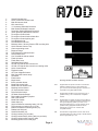
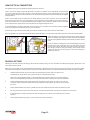
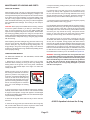
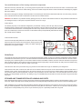
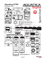
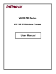
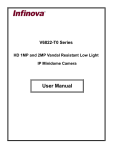
OPERATING MANUAL FOR AQUATICA A70D
PRODUCT # 20074
Content
Foreword and feature
Page 1
Safety recommendations
Page 2
Nomenclature of controls Page 3
Summary of controls and components location
Page 4
Controls and components in detail
Page 5 & 6
Preparation of the housing
Page 7
Preparation of the ports
Page 7
Camera preparation and installation Page 8
Closing procedure for the housing
Page 8
Preparation and installation of the lens
Page 9
Selecting focusing mode
Page 10
Mounting a port and/or extension on the housing
Page 10
Connecting lighting equipments to the housing
Page 11
Using wired connectors Page 11
Using optical connectors
Page 12
Basic procedure for taking a picture
Page 12
Maintenance of the housing and ports
Page 13
Care and maintenance of the housing mechanical components Page 14
Care and maintenance of the ports
Page 14
Storage and transportation of housing and port
Page 14
Housing System accessory chart
Page 15
Warranty Conditions
Page 16
FOREWORD
Thank you for having selected the AQUATICA Digital Camera System for your underwater photography needs.
The AQUATICA Digital Housing is the result of a long and continuing relationship with the most demanding underwater photographers in
the world. Each housings is handcrafted, tightly quality controlled and pressure tested to a 300 feet/90m equivalent by a small group of
specially trained individuals, each of whom takes the utmost pride and satisfaction in offering you the best underwater camera housing
in the world.
The Aquatica Digital Housing was designed for optimum technical and optical performance and to provide easy and efficient underwater
access to the essentials functions and controls of the Canon 70D DSLR. This operating manual assumes that the user is already familiar
with the Canon 70D camera and its operation. If not, please read your Nikon instruction manual before attempting to use the housing.
With basic care and a regular maintenance schedule, your AQUATICA housing will provide years of enjoyment and satisfaction in producing
spectacular underwater images.
Please take the time to carefully read this manual before attempting to use your housing for the first time and note that: whenever cited
the right hand is your right when using the housing.
This Aquatica Digital housing is issued from the world’s most technologically advanced underwater housings lineage, ergonomically
designed to place all the essential camera controls under your finger tips and features the following:
-
Large ergonomic and easy to operate controls for most of the manual and computerized camera
functions, including the following controls:
- Extended Mechanical Shutter Release Lever.
- Large knurled knob for accessing Shutter speed control.
- Large knurled knob for accessing Aperture control.
- Oversized knurled knob for accessing the Focus or Zoom feature of the lens
- Dual positions lever for accessing the AF-ON and STAR functions
- Easy access knob for Exposure mode control (Mode)
- Exposure Compensation
- Focus Area Selector
- Extended ISO sensitivity lever
- Info & Playback
- Menu and controls
- Delete button access
- Live view & Video recording access
-
A quick release camera tray (saddle), for fast and easy removal of camera.
-
A flexible strobes connector circuitry to suit your personal needs (see page 11&12).
-
A new redesigned moisture alarm with integrated vacuum sensor
-
A port locking mechanism to prevent accidental rotation of the port or extension mounted on the housing
-
A complete selection of bayonet mounted ports including dome ports of 4”, 6”, 8” and 9.25” diameter, three flat ports and a
large selection of extension rings to preserve the image quality of your lenses.
-
A Lens Lock Release control that will activate the lens release button of the camera from the outside of the
housing, this lever can be pulled out to allow the camera/lens/gear to be removed together for easy replacement
of the camera battery.
-
A comprehensive selection of focus and zoom gears to access all popular lenses useful for underwater photography,
-
A choice of standard eye piece finder (included), Aqua View 180 finder (# 20054) and Aqua View 45 Finder (# 20059).
-
Bulkhead entry point for external Monitors, remote triggering accessories, including the pole mounted RCS remote camera
system.
Page 1
SAFETY RECOMMENDATIONS
Please carefully read the following precautions and recommendations:
Improper transportation, handling or use of this housing might cause a flood or malfunction. See Storage
and transportation of housing and ports section on page15
Never remove, change a port or open the housing in a location where sand or similar foreign material
might come in contact with an O-ring. Be wary of strong wind as it could potentially be carrying sand.
Always perform a simple seal test without the camera inside after doing maintenance.
Non authorized use of third party accessories, as well as modifications and/or alterations not specifically
authorized by Aquatica may affect performance, cause poor functioning of the controls or impair the
sealing integrity of the housing.
Always handle port carefully, like the sensitive optics they are, protect them when not in use to avoid
scratching the acrylic or glass surface of the ports and windows.
Always confirm that the ports remain properly attached before rinsing the housing. An optional port
locking collars is available (#18469) for securing larger dome to the extension ring. When rinsing without
a wired strobe, confirm that the bulkhead strobes connectors are sealed with their plug.
Page 2
1
5
4
36
38
39
6
7
10
8
9
2
3
13
16
11
NOMENCLATURE
12
14
Made in
CANADA
43
18
17
15
28
20
35
34
21
23
43
22
5
27
26
19
24
25
30
29
33
32
2
MENU INFO
31
14
41
10
9
40
8
7
45
6
Top controls
37
1
4
39
3
44
AF
36
DRIVE
44
38
35
34
42
24
22
46
47
5
4
2
22
25
7
6
1
24
25
48
8
42
35
34
9
47
47
47
48
21
12
2
3
49
49
50
Page 3
51
52
18
52
51
50
1-
2-
3-
4-
5-
6-
7-
8-
9-
10-
11-
12-
13-
14-
15-
16-
17-
18-
19-
20-
21-
22-
23-
24-
25-
26-
27-
28-
29-
30-
31-
32- 33-
34-
35-
36-
37-
38-
39-
40-
41-
42-
43-
44-
45-
46-
47-
48-
49-
50- 51-
52-
Shutter Release lever
Quick Control Dial access knob
Main Dial access knob
ISO control lever
½” Accessory Bulkhead Connector
Main Strobe Bulkhead Connector
Secondary Strobe Bulkhead Connector
16mm Accessory Bulkhead Connector
Focus/Zoom Control knob
Focus/Zoom Control knob release disc
Focus/Zoom Control pinion gear
Lens Release knob
Lens Release knob lever
Moisture Alarm / Vacuum Sensor LED mounting hole
Quick Release Camera Tray
Camera mounting screw
Bayonet Flange
Port Release mechanism button
On/Off switch lever
Live View/Movie selector switch
Flash Up button
Flash down Lever
Start/Stop Movie button
AF-ON / AF-Start & Star access lever
AF-ON / AF-Start & Star access lever rotating collar
Quick Control Button
Playback button
AF Point / Magnifier button
Multi Controller buttons array.
Set button
Erase button
Menu button
INFO activation button
Mode Dial access knob
Mode Dial lock release lever
Metering selector button
AF Area selection button
Drive Selection button
AF Mode Selection Button
Removable Viewfinder Eyepiece
Rear LCD window
Mode Dial window
Hand Grips (x2)
Grip’s Accessories mounting holes (1/4”-20)
Top Accessory mounting hole (1/4”-20)
Bottom Accessories mounting holes (x3)
Rubber Anti Skid pad
Sacrificial Anodes (x2)
Closing Latches (one per side)
Closing Latches Safety locking tab (one per latch)
Closing Latches strikes (one per side)
Mounting points for the hand grips
Page 4
-NK
-OPT
-HYB
-KM
Housings strobes connection variants:
-OPT
Supplied with two optical connections. Included are
adapter for attaching two Inon type (straight tip)
sync cords or two Sea & Sea type sync cords. S-TTL
is possible if using appropriate strobes
-NK
Supplied with two Nikonos Type connectors. TTL is
possible if using a TTL converter with compatible
strobes.
-HYB
Supplied with one optical connector and one Nikonos
type connector. Included are adapter for attaching two
Inon type (straight tip) optical sync cords or one
Sea & Sea optical type sync cords. Optical S-TTL is
possible if using appropriate strobes as well as
standard TTL if using a TTL converter with
compatible strobes
-KM
Provided with a single Ikelite connector. This can be used with Ikelite type cords for single or double strobes
with the appropriate sync cord.
CONTROLS IN DETAIL
1- SHUTTER RELEASE LEVER: Pulling the shutter release
lever back part way activates the camera meter and auto
focus. Pulling the lever back all the way fires the camera.
2- QUICK CONTROL DIAL ACCESS KNOB: It rotates clockwise
and counters clockwise. It can be used alone or in combination
with other controls to select or set various camera functions
or modes. Refer to your camera manual for in depth use.
13- LENS RELEASE KNOB LEVER: Applies pressure on
the camera lens lock button.
14- LED MOUNTING HOLE: this mounting hole is provided
for the moisture alarm/vacuum sensor warning LED.
15- QUICK RELEASE CAMERA TRAY: Used to attach the
camera and slide it in place inside the housing.
3- MAIN DIAL ACCESS KNOB: Rotates clockwise and
counter clockwise. Use alone or in combination with other
controls to select or set various camera functions or modes.
In “Manual” this controls the shutter speed settings. Refer to
your camera manual for in depth use.
16- CAMERA MOUNTING SCREW (1/4”-20): Used for attaching
the camera to the Quick Release Tray.
4- ISO: Press on lever to engage the ISO speed value button
of the camera
18- PORT RELEASE MECHANISM LEVER: Pressing on
this lever will release the locking mechanism when the removal
of a port or extension is needed.
5- ACCESSORY BULKHEAD (1/2 INCH): This bulkhead
passthrough hole can be used for mounting accessories
such as a remote trigger, a vacuum valve or a monitor.
6- MAIN BULKHEAD CONNECTOR: This bulkhead connector
is normally used as the main connection, configuration may
vary according to an owner’s preference, (see page 11)
7- SECONDARY BULKHEAD CONNECTOR: This bulkhead
connector is normally used as the secondary connection,
configuration may vary according to an owner’s preference,
(see page 11)
8- ACCESSORY BULKHEAD (16MM): This bulkhead
passthrough hole can be used for mounting accessories
such as a remote trigger, a vacuum valve or HDMI monitor
9- FOCUS/ZOOM KNOB: Turning will rotate the attached
gear mounted to the zoom mechanism or focus ring of a
lens.
10- FOCUS/ZOOM KNOB RELASE DISC: Lifting and rotating
this disc to its resting post, will retract the pinion gear (# 11);
doing so, along with pulling the lens release lever outward
(# 12) will allows the camera and lens, with a gear attached
to it, to be removed from the housing as a single unit.
11- FOCUS/ZOOM PINION GEAR: This gear connects and
operates the focus or zoom gear attached to the lens.
12- LENS RELEASE KNOB: It Activates the lens release
button on the camera allowing easy removal of the lens, pulling
this out along with the zoom knob release disc (# 10) will
allows the camera and lens to be pulled out from the housing
as a unit.
17- BAYONNET MOUNTING FLANGE: allows the mounting
of different ports and extension rings on the housing.
19- ON/OFF SWITCH LEVER: Rotate to turn the camera
power ON or OFF.
20- LIVE VIEW / MOVIE SELECTOR SWITCH: Rotate left
or right to select Live View or Movie mode.
21- FLASH UP BUTTON: Push to raise the integrated flash
of the camera (used with –OPT and –HYB version)
22- FLASH DOWN LEVER: Pull to lower the integrated flash
of the camera (used with –OPT and –HYB version)
23- START/STOP: MOVIE BUTTON: This oversized red button
activates recording in the video mode.
24- AF-ON / STAR ACCESS LEVER: This lever can be pull
outward or inward to access both the AF-ON feature and the
Star customizable button, theses are important controls for
video shooting and care should be taken to fully understand
their working and subtleties.
25- AF-ON / STAR ACCESS LEVER ROTATING COLLAR:
Pull the AF-ON / STAR Lever and rotate this collar into
position, to select access to the AF-ON or the STAR button
of the camera.
26- QUICK CONTROL BUTTON: Press to activate the LCD
menu display. You can then navigate using the Multi controls
buttons array (# 29) in combination with the Quick Command
Controls (# 2) and/or Main command control (# 3).
27- PLAYBACK BUTTON: Press to activate the monitor and
review images.
Page 5
CONTROLS IN DETAIL, CONTINUED
28- AF POINT SELECTOR / MAGNIFIER BUTTON: Push to
select the desired AF pattern or to magnify an image on the
rear LCD.
29- MULTI CONTROLER BUTTON ARRAY. Use to navigate
through the multiples options of the menus, modes and features
of the camera.
30- SET BUTTON: Press to approve selection of menu or
chosen mode features.
31- ERASE BUTTON: Press to delete images.
32- MENU BUTTON: Press to activate menu display, scroll
using main or quick dial control knob and select using SET
function button
41- REAR WINDOW LCD: This port window allows viewing
of the recorded images and is used in the Live View and
Video mode for framing and composing. It also allows viewing
of the entire menus selection as well.
42- MODE DIAL WINDOW: This port window give the user a
visual of the camera mode dial.
43- HAND GRIPS (X2): Left and right grip allowing the mounting
of strobe arms and accessories, these are attached with the
supplied bolts and hexagonal wrench..
44- GRIPS ACCESSORIES MOUNTING HOLES: Two 1/4-20
TPI holes on each grip are ready to accept TLC Base Brackets
or TLC Base Ball for strobe arms or accessories.
33- INFO BUTTON: This button will activate the rear LCD
and display all pertinent shooting information.
45- TOP ACCESSORY MOUNTING HOLE: a 1/4”-20 TPI
hole is supplied to accept a TLC accessory or TLC base ball
for mounting a strobe arm or a modeling light.
34- MODE DIAL ACCESS KNOB: Rotate to select the proper
shooting mode, (care should be taken to understand the
various combinations available).
46- BOTTOM ACCESSORIES MOUNTING HOLES: Three
1/4” X 20 holes are provided for mounting strobes trays or
accessories.
35- MODE DIAL LOCK RELEASE LEVER: This lever
disengages the lock on the mode dial of the Canon 70D.
Once it is engaged; the mode dial can be rotated using the
Mode Dial Access Knob (# 34).
47- RUBBER ANTI SKID PADS: Six (6) rubber pads are provided
to protect the housing and preventing it from sliding on wet
decks.
36- METERING PATTERN BUTTON: Press to select the
appropriate metering mode.
37- AF POINT SELECTION BUTTON: Press to select the
preferred type of AF mode.
38- DRIVE SELECTION BUTTON: Press and use the Quick
Control Dial access knob (#2) or the Main Control dial access
knob (#3) to alternate between the various drive and self
timer modes.
39- AF MODE SELECTION BUTTON: Press and use the
Quick Control Dial access knob (#2) or the Main Control dial
access knob to alternate between the various modes (ONE
SHOT, AI FOCUS & AI SERVO).
40- REMOVABLE VIEWFINDER: This Galileo type view finder
offers a full view of the illuminated camera viewfinder display.
All necessary information is visible. This viewfinder can be
removed and replaced with one of our two optional Aqua
View Finders, which are available in 45o & 180o version, for
a larger displayed image.
48- SACRIFICIAL ANODES: (2X) zinc anodes are installed
to protect your housing against salt water corrosion; theses
are made to deteriorate easier than the other strategic part
of your housing, hence the name sacrificial anodes. These
anodes need to be replaced by the user as needed.
49- CLOSING LATCHES: Two heavy duty latches equipped
with safety locks (# 50) to protect against accidental opening.
50- CLOSING LATCHES SAFETY LOCKING TAB: These
are safety locking tab that prevent accidental opening of the
latches (#49).
51- CLOSING LATCHES STRIKES: Those will hook up to
the latches for a secure closing of the housing.
52- MOUNTING HOLES FOR GRIPS: A threaded 5/16’’ hole
is provided on each side for mounting the housing grips
(# 44), see care and maintenance section.
Page 6
PREPARATION OF THE HOUSING
Two Grips for both right and left hand grips are provided,
these attach on the sides of the housing with the supplied
screws and hexagonal wrench.
Mount the necessary shoes or brackets onto the 1/4”-20
threaded holes located on the top of the hand grips. Three
threaded holes of the same size are located on the bottom
of your Aquatica housings for mounting accessories such
as lighting support, trays, brackets or tripod. A similar sized
hole, located on the top the housing, allows the mounting
of a video light, focusing light, TTL converter support or
buoyancy compensating devices.
Mount your strobes and their arms on the housing and
connect the sync cord to the housing’s strobe bulkhead.
Before using electrical type sync cords, carefully read the
section (page 11) pertaining wired connection and refer
and follow your strobe manufacturer manual and their
recommendations.
For proper handling and maintenance of O-rings be sure
to read the section titled “Maintenance of the housing and
ports” (page 14).
The Aquatica 6” and 8” dome ports have removable Dome
Shade, without the shade, a circular 180o Fisheye lenses
can be used to its full potential, when using standard type
of lenses, the use of a dome shade is highly recommended
as it improve contrast, reduce glare and offer an added
protection for the dome delicate surface
A comprehensive lens chart listing of the lenses supported
and their required extensions and/or accessories is supplied
at the end of this manual. For the latest updated version
of this lens chart, Please refer to the Canon Type 2 Lens
Chart available on our website:
http://www.aquatica.ca/en/products_zoom.html
Cleaning the port:
Dirt, grease or fingerprints on the port especially on the
inside, can adversely affect the quality of the image. Acrylic
ports should be cleaned with plastic cleaner and glass
ports with an appropriate lens cleaner.
Lubricating the port and extension ring O-ring seal:
Before using a port or extension ring, remove the O-ring
on the rear and lightly coat it with silicone grease, clean its
groove before installing it back.
PREPARATION OF THE PORTS
Underwater photography typically requires the use of a
dome port for Wide Angle or a flat port for close up and
macro photography. Your lens and subject selection should
dictate the type of port you select. Flat Macro Ports are
available in three (3) version (product # 18426, 18428 or
18429), and Dome Ports in four (4) sizes ranging from 4” to
9.25” (Product # 18405, 18407, 18409 or 18410).
For more information concerning the care and maintenance
of your ports and their O-rings, please refer to the section titled
“Maintenance of the housing and ports” Starting (page 14).
There are occasions where an extension ring might be
required to either, optimize the optical performance of a
dome, or for adding sufficient space to accommodate a
longer macro lens:
Macro Port Extension Rings: These aluminum rings extend the internal space of a Flat Macro Port, some shorter
macro lens do not require using one, but longer lenses
(100mm and longer) will need one in order to provide the
necessary space to accommodate them.
Dome Port Extension Rings: When using a wide angle
or zoom lens, the Dome Port may require the use of an
extension ring, this is done both for physically accepting
the lens and to closely match the position of the optical
center of the dome and the lens as can possibly be done.
Page 7
CAMERA PREPARATION AND INSTALLATION
Important Note: Prior to installing the camera in the housing, remove the rubber eye cup (illustration #1),
the camera strap and clips, and/or any object that might obstruct installation, third party camera strap
hookup should be removed. It is advisable before inserting the camera in the housing, and in order to
save valuable time underwater, to preset your camera shootting preferences in advance,
1- Remove the quick release tray (# 15) from the housing by pressing down on the metal tab (A) and
pulling the tray out (B) as shown in Illustration #2. Carefully place the camera on it, making sure that
the camera is properly aligned and secured against rotation or movement on the alignment pin (C) as
seen in illustration #3. Align the Tripod Socket of the camera with the mounting screw (# 16). Tighten
the mounting screw securely while ensuring that the camera position is not altered.
Illustration # 1
2- Pull out the lens release lever
(#12) as per illustration # 4
Illustration # 2
3 - If using the optional Hydrophone
connect the plug to the camera
audio jack, and tuck the rubber
flap of the microphone plug safely
out of the way.
Illustration # 3
4 - Slide the quick release tray (# 15) back into place; it will lock itself into place.
Illustration # 4
CLOSING PROCEDURE OF THE HOUSING
Before closing the housing always confirms that:
1.
The camera quick release tray is securely locked to the front half of the housing.
2.
If using electrical sync cord, that the hot shoe connector is properly inserted
on the camera shoe as seen in illustration at right. That all cords or wires are
tucked in so that they will not interfere with the closing of the housing.
3.
The main O-ring of the housing is well lubricated, clean and properly seated
for a positive seal and its opposing sealing surface is clean and free from
any scratches or physical damage.
4.
The controls of the ON / OFF control (key # 19) and the Live View control
(key # 20) of the housing are in the same position on both the housing and
camera, as per illustration # 6 & # 7.
Then simply join the front and rear halves of the housing using the two dowel pins on
the housing as guides.
Illustration # 5
Live View switch position of housing and camera
Illustration # 6
Hold the housing with both hands and looks around the sealing surface to confirm
that the O-ring is properly seated and that no cords, wires are caught between the
edges. Close the two latches simultaneously.
CAUTION: If you feel any unusual resistance as you attempt to close the
latches, do not force the closure. Check for any obstruction and
try again.
Power switch position of housing and camera
Illustration # 7
Confirm that the spring loaded safety tabs of the latches (key A) are properly engaged
in order to prevent the closing latches from opening accidentally. Simply try to lift the
latch if the tab (A) is engaged, it should not be possible to do so without first disengaging the safety tab.
Be mindful when opening the housing, the pressure build up inside the housing may exaggerate the release force
of the latch spring. Keep fingers safely away from the path of the latches.
Page 8
PREPARATION AND INSTALLATION OF THE LENS
There are a number of lens gear available and various way of mounting them to a lens, all depending on their design. Using the right gear
and correctly mounting it on the lens is a very important step for a smooth operation of the Zoom or Focus control. Carefully follow the directions
found on each gear packaging. Please note that the use of Canon EF and EF-S compatible lenses is mandatory. A comprehensive list of the
supported lenses for this housing and their respective gears and domes ports is supplied along with this manual. The lens charts are regularly
updated as newer lens are made available, for the latest available version of this housing lens chart please visit our Lens Chart section at
http://www.aquatica.ca/en/products_zoom.html
Notes: On some lens /dome port combination, a close up lens (Diopter) might be required or desirable. This is intended to correct the minimum
focusing distance of the lens so that it can focus on the virtually projected image created by the dome. Refer to the appropriate lens chart to
see if a diopter is required for your lens/port combination.
Zoom lenses: Mount the gear on the lens zoom ring. The housing focus/zoom control (key #9) then becomes the exclusive method of
controlling the zoom. Focusing of the lens is then achieved by using the camera’s autofocus system, or on certain Wide Angle zoom lens, it
will be possible to access the manual focus via a dedicated port extension ring equipped with a manual focus access knob
Prime Lenses: They can be used in Auto Focus or if a focus gear is available for this particular lens, it can be operated in manual focus. For
Manual operation, the camera focus selector need to be set to the manual focus position, then a focusing gear (if available for this lens) will
need to be mounted on the lens.
WARNING: If the lens is a not of the USM type, never attempt to operate it with the camera in autofocus mode with a mounted focus gear
engaged. This will strain the focus mechanism motor and might damage your lens.
Gear installation on the lens:
Slip-on gears (gears without mounting screws): Slide the gear over the lens and align on the Focusing or Zoom ring or push until the gear
cannot move any further up the lens.
Gears with adjustment screws: Tighten the set screws lightly and evenly, approximately ½ a turn at a time, carefully working your way around
the gear until all the screws are equally tightened, verify that the zoom and/or focus mechanism rotate smoothly and that the gear remains
concentric with the lens body.
CAUTION: Do not over-tighten the set screws, doing so might bind the lens and restrict the rotation of the Focus or Zoom ring and possibly
damage the lens mechanism. Conversely under-tightening these screws might cause the gear to slip or lose its alignment.
LENS INSTALLATION
Note: Always take extra precaution to protect the sensor from airborne dust or particles whenever
installing or removing a lens.
With the camera installed the housing, push the lens release lever (key #11) into the proper position
so has not to obstruct it operation later, through the port opening in the front of the housing install
the lens in the normal recommended way. If the lens is equipped with a zoom or focus gear, confirm
that the gears are properly installed and aligned. Check the meshing of the lens gear with the pinion
gear (key #11) on the housing by rotating the Focus/Zoom control knob (key #9) several times to
make sure the gear rotates smoothly and does not slip.
CHANGING A LENS (REMOVING A LENS)
The Aquatica Housing provides two methods for removing and replacing a lens. It can be done
either from the front by removing the port or through the rear, by removing the camera mounted on
its quick release tray (key #15)
From the front: unlock and remove the port and/or extension ring (see chapter: Mounting a port and/or Extension ring on the housing). If a
gear is mounted on the lens, access to the camera lens release button is still possible using the lens release lever (key #11) on the housing.
Or
Pull out the Lens Release Lever (key #11) out of the way, lift and rotate the Zoom Focus Release Disc (key #10) clear, open the housing
back cover, remove the hot shoe from the camera and pull out the complete camera & lens from the housing, replace the lens and reinstall
in the reverse order.
Page 9
FOCUSING MODE
NOTE: Select the proper focus mode with the AF focus mode selector button (key # 39) and using the quick control (Key # 2) or the main control
(key # 3) pressing button (key # 28) on the back of the housing to access the pattern options with the Quick command Knob (key # 2), the Main
command knob (key # 3) or using the Multi Control Array (Key # 29) . For more detailed information concerning the operation of the different
focus modes consult the Canon ® instruction book for the 70D. Taking full advantage of the AF-ON and Star (*) lever access on the housing
dedicated lever (# 24) can also greatly contribute to the performance of the autofocus performance underwater.
MOUNTING A PORT AND/OR EXTENSING RING ON THE HOUSING
Safely mounting a Port or extension on the housing requires that the O-ring be clean, lubricated,
be properly seated in its groove and that the opposing sealing surface be clean and free of any
physical damage.
This AQUATICA A70D Digital Housing features a locking bayonet mount (Key #17), to mount a
port or extension ring on the housing:
1. Place the housing on its back on a soft and steady surface.
2. Place the port or extension ring inside the bayonet of the housing. Align one of the four alignment
notches with the opening of the housing.
3. Place your hands on opposite sides of the port or extension ring.
4. Push with even force on both sides of the port or extension ring until you feel it snap into place. Make sure the bayonet is completely
inside the housing.
5. Rotate the port clockwise until it stops. Do not force it. If there is too much resistance take the port off, check the O-ring and see that
the port or extension are properly seated before attempting to rotate again.
6. Try to rotate counter clockwise to confirm that the port or extension is safely locked on the housing.
7. When using large dome port such as the 6”, 8” and 9.25” with an extension, uses of the optional extension ring to port locking collar
(# 18469) is recommended, this will add another layer of safety by preventing the larger dome port from rotating during manipulation or
transportation to the dive site.
To remove a port or extension from the bayonet, press the port release lever (key #18) and rotate the port or extension counter clockwise,
carefully pull the port or extension off the bayonet.
Note: It is recommended that you familiarize yourself with this procedure by trying it without the camera in or the back cover attached to
the housing; this to better visualize the internal functioning of the bayonet and port.
Page 10
CONNECTING LIGHTING EQUIPMENT
Aquatica housings can be adapted to various types of strobe connectors. This feature
conveniently provides your camera system with access to the latest strobes
technology currently available on the market.
Standard options available are:
20074-NK: Two Standard Nikonos type 6 pins connectors.
20074-OPT:
Two optical fiber connectors with adapter to accept two
Sea & Sea angled type cords or two straight type cord (INON).
20074-HYB
One Nikonos 6 pins and one Optical connector (to accept
either one Sea & Sea elbow type cord or two straight
standard Inon optical cords).
20074-KM
One Ikelite manual type connector
Mounting the strobe arms will require that the necessary shoes, brackets or Base
Ball be attached to the threaded holes located on the top of the hand grips (key # 44). Use
of the Aquatica Technical Lighting Control Strobe Arm System is recommended.
Three 1/4”-20 threaded holes on the bottom (key # 46) of this housing can be used
for various mounting applications. A similar sized 1/4”-20 hole with thread is located
on top of the housing (key # 45), and is ready to accept a Technical Lighting Control
1”/25mm Ball (# 17651) for adapting a small dive light or an additional strobe arm
can be attached using a clamp.
USING WIRED CONNECTORS
Internal switch board circuit:
Aquatica housings are available with electrical type strobe connectors; these come in single or double configuration, and are connected to an internal
switchboard inside the housing. The following chapter explains the various options available and the limitation of current underwater strobe technology.
When preparing the sync cord, be sure to lubricate the O-ring on the sync cord’s connector with a light coat of
the manufacturer original O-ring lubricant, also advisable is to put a light coat of O-ring lubricant on the threads
of this connector to help prevent threads from freezing up. Some electrical sync cord are known to use dissimilar
metal in their construction, these can create an unwanted electrolytic reaction, if using sync cord with metal fitting,
it is recommended that you remove them, and clean and lubricate the thread on a daily basis.
ON
1
GTS
2
3
4
ON
OFF
Canon Digital cameras are setup with a flash circuitry that only allows one eTTL flash to be connected directly to
the camera, Canon TTL Protocol will not allow two TTL flashes to be electrically connected directly, no matter if it is a Canon flash or any other brand. The
multiple flashes approach preferred by Canon prevents additional flashes, or strobes from being connected directly to the camera in eTTL mode, exposure
will stop to function and a camera freeze is likely to happen. Two underwater strobes can only be connected electrically if a TTL converter is interfaced
between the camera and the strobe. If seeking TTL exposure, Optical triggering is a accurate and inexpensive way to consider (see next chapter)
On your housing you will find either one or two bulkhead connectors, the main connector (on right side) is wired through a switch board that can be configured
for full manual flash exposure or setup to be compliant with the latest TTL converter on the market. The secondary connector (left side if installed) is wired
in a full manual configuration and cannot be used for eTTL operation. By default you housing is delivered with the switch board set to full manual, if eTTL
exposure is desired then it can be made in either of two methods:
1) Using a single flash from Canon or other brand (that is eTTL compatible with your camera) in a dedicated underwater housing connected with a TTL
cord to the Nikonos 6 pins main connector of your Aquatica housing.
2) Using an external eTTL converter connected to the main connector of your Aquatica housing, one or two underwater strobes with TTL cords can then be
connected to this converter, (check with your dealer or the strobes manufacturer to see if the strobes and converter are compatible between themselves).
Set up instruction for eTTL operation: Using the tip of a pen push all the switches to the ON (up) position, this will activate the connections on your main
bulkhead connector allowing TTL communication between the camera and the housed flash or iTTL converter.
Set up instruction for manual operation: All switches must be in the OFF (lower) position, in this case all eTTL connection are disabled and only the
ground and sync are left active, this will allow two under water strobes or housed flashes to be connected directly via the main and secondary bulkhead.
Page 11
USING OPTICAL CONNECTORS
This Aquatica housing can be supplied with optical type strobe connection:
Version –OPT is fully optical, having dual optical type of connection. Included is one (1) dual adapter for typical straight
cord used by INON and various other optical sync cords manufacturers and two (2) Sea & Sea/Olympus type of angled
cord plug, select the desired connection and install on the optical port base, tighten the set screw into place with the supplied
hexagonal wrench.
Version –HYB is supplied with one optical and one Classic Nikonos type of strobe connectors. As well as the Nikonos
electrical connector, Included is one (1) dual adapter for typical straight cord used by INON and various other optical sync
cords manufacturers and one (1) Sea & Sea/Olympus type of angled cord plug, select the desired connection and install
on the optical port base, tighten the set screw into place with the supplied hexagonal wrench.
To use optical triggering, the built-in flash of the camera need to be in the up position, this can be done at time of installation
or later by pressing the flash actuator button (key # 21) to release it.
INON Type Straight cord
Sea & Sea Type angle
If ambient light images need to be taken simply push the flash actuator lever (key #22) to close the internal flash.
Note: it is advisable to turn the camera and external strobe off when travelling to your dive site to avoid useless drain of the camera and strobes batteries.
NOTE: Field testing has shown that mixing brands of optically triggered
strobes is unlikely to give reliable TTL results, therefore it is suggested
that when mixing different makes of strobe, that they be used in manual
mode.
On the –HYB version, installing the hot shoe will disengage and prevent
the built in flash of the camera from coming up when needed. Tuck the
hot shoe and its ribbon wire safely away from the path of the built in
flash. Always confirm the raising and lowering of the built flash before
entering the water and do test exposure to insure that everything is
operating as it should.
TAKING A PICTURE
Following are the basic techniques for taking a picture with the Aquatica housing. For more information and advanced photography, please refer to the
Canon 70D instruction manual.
NOTE : It is recommended, in order to save valuable time underwater, to establish a pre dive check list and arrange your setting such as metering pattern,
color balance, ISO and exposure mode ahead of time, The Canon 70D does offer a convenient “C” custom shooting mode memory that can register your setting.
1. Rotate the Mode dial knob (key # 34) and select the desired exposure mode. Options in sequence are:
Programmed (P), Shutter Priority (Tv), Aperture Priority (Av) or Manual Exposure (M).
Note: When using underwater strobes, it is recommended that the camera be used only in Single Frame Motor
Drive to avoid the possibility that the camera could fire before the flashes or strobes can fully recycle themselves.
3. Push the Metering Pattern button (key# 36) and select the metering system symbol you wish to use in the rear
LCD panel. select the preferred focusing method using either the AF point selector (key # 28) or AF area selector
(key # 37)
4. Pull the Shutter Release Lever (key # 1) partially back. This will activate the camera’s meter and autofocus system.
5. For using manual focus use the Focus Knob (key # 9) or the knob located the side of the flat port or extension to focus the lens.
6. If using the Manual or Shutter mode adjust the main dial knob (key # 3) or Quick command dial (key # 2) to set the
exposure.
7. Pull the Shutter Release Lever (key # 1) the rest of the way until the camera fires.
Page 12
MAINTENANCE OF HOUSING AND PORTS
5. Wipe the matching sealing surface part of the housing with a
clean lint-free cloth.
USING THE HOUSING
When changing ports or O-rings, a simple seal test without the
camera inside should be performed. Strapping a weight to the
housing and lowering the unit to a depth of 30 to 50 feet of water
for at least 10 minutes will assure you that the seating of the
new port or o-ring is proper. This test, though time consuming and
often considered unnecessary, may save your camera equipment
from irreparable water damage. The housing is now ready for
the dive.
CAUTION: Never jump into the water with the housing. It is best
to have the system handed to you after you have made your
entry, or have it lowered to you on a rope. Make certain that
ropes of other equipment stay clear of the system. Never handle
the housing by grabbing the port or if using one, the Aqua View
Finder, make sure that boat staffer are familiar with this procedure
and advise them to manipulate only by using the grips provided
with the housing.
When replacing the main sealing O-ring, place the entire O-ring
over the O-ring groove and start by pushing the O-ring in the
corners. Work your way around the O-ring making sure it is
snugly sitting in the groove. Avoid going solely in one direction
as doing so will stretch the O-ring material and possibly prevent
it from properly seating.
CARE AND MAINTENANCE
TO SERVICE O-RINGS OF THE HOUSING, PORTS AND
EXTENSION RINGS
1. Removing an O-ring: It is important never to use a sharp
instrument when removing an O-ring as this may damage the
sealing surface of the groove or the O-ring itself. A dedicated
O-ring tool, a dull pointed object or the edge of a credit card
usually works well.
7. Confirm that the Port and extension ring O-rings are properly
and evenly seated in their O-ring groove.
8. To reinstall the clean and lubricated main O-ring of the housing,
first place the entire O-ring over the groove and start by pushing
the O-ring in at each corner then, push the O-ring at each side
and finally, work in the rest of the O-ring. Never start at one end
and work your way around the O-ring. This places uneven
tension on the O-ring which may cause the O-ring to stretch
resulting in excess O-ring, which will have no place to go.
The internal O-rings on the housing controls are not user
accessible, while these O-rings are not as susceptible to damage
as they are not exposed, rinsing properly with fresh water to
flush out salt crystals and sand residues will be the proper way
to assure trouble free operation, Aquatica recommended yearly
maintenance of the internal O-ring. Authorized service center,
both the continental USA and Europe, are available to the users
for this service. Prior to sending the housing, always check for
the closest service center to you on our website www.aquatica.ca
WARNING: Use only petroleum free O-ring lubricant such
as our # 19213 Aquatica O-ring Lubricant, petroleum based
lubricant, used by some manufacturers for lubricating their
Silicone made O-rings can and will cause the O-ring material
to swell, this will render the O-ring difficult to install and
likely will result in the O-ring being damaged or pinched
with dire consequence.
ENTRY POINT
OR
INVERTED “ V” GROOVE
2. Once removed, the O-ring should be inspected for damage.
Carefully check that it is free of nicks or cuts and that it retains
its original round profile. O-rings that appear to be damaged
should be immediately replaced with new ones and the damaged
one permanently discarded.
3. Rinse the O-ring with fresh water and dry it with a clean lint
free cloth.
4. Clean the O-ring groove (the channel where the O-ring sits)
with a cotton swab. Be sure to remove any lint the cotton swab
may leave behind. Inspect the groove for damage.
Page 13
UBRI
GL
C
IN
NT
A
NOTE: the main O-ring in the back of
the housing is inserted in an inverted V
groove to prevent it from popping out,
to remove, use a dull pointed object and
insert in the side of the small opening
on the lower left hand side of the front
part of the housing (illustration at right).
Do not use sharp objects or excessive
force; this could damage the sealing
surface.
6. Lubricate the O-ring with a thin layer of Aquatica O-ring
lubricant (# 19213) until it appears to be smooth and shiny.
Do not over lubricate. Use just enough lubricant so the O-ring
will pull smoothly through your fingers. Excessive amounts of
grease will only serve to attract and trap dirt onto the o-ring.
MONTREAL, CANADA
TEL. 514-737-9481
WWW.AQUATICA.CA
# 19213 Aquatica Lubricant for O-ring
Care and Maintenance of the housing mechanical components:
After each and every salt water dive, your housing system requires that it be soaked and/or rinsed in fresh water. it should soak in fresh
water for a minimum of 30 minutes. while soaking, reach into the water and operate all the controls several times to dislodge any trapped
salt water residues.
Remove the hand grips for storage and transportation to avoid having the thread of the attachment bolts fuse on to the housing. Unscrew,
clean and lubricate the bolts with a small amount of WD-40 or Zinc based lubricant.
WARNING: Use WD-40 or any lubricant carefully, sparingly and only on metal to metal surfaces. WD-40 or other petroleum based lubricant
can damage the acrylic on the ports, the optical surfaces of a lens or O-rings.
Of the Latches:
The latches (key #49) on the AQUATICA Digital are provided with a locking action tab (key #50) to prevent
accidental opening. Always ensure that the locking tab mechanism is secure. Watch for the build-up of corrosion
or salt residue around the latches. This will appear as a white crusty material. Clean frequently with a stiff brush
(such as a toothbrush) to remove the corrosion or salt residue build-up and periodically lubricate these latches
with a small amount of WD-40.
Of the sacrificial anodes:
The two anodes (key #48) attached to the bottom parts of the housing
are there to prevent corrosion due to electrolysis, as time goes they will
deteriorates and need replacement, contact your dealer acquiring for
replacement ones (parts # 19220).
Of the Ports:
Your ports are part of the optical formula of your underwater photographic system; As such they should be treated with the same attention
as the delicate camera lenses you own. Care should be taken with the Dome Port and Macro Port to avoid scratches on the lens surface.
The acrylic port is softer than glass so minor exterior marks are often unavoidable. However, since the indices of refraction for acrylic and
water are almost identical, the scratches should not seriously impair image quality. Internal scratches (air side) must be avoided as they
do not fill in with water and can affect the quality of the image.
Clean the dome and macro port lenses using only products recommended for the type of material they are designed for.
Clean the dome lens with a soft lint free cloth. Dust on the interior surfaces of the port can be removed with a soft camel hair brush or
a blower brush. Caution must be taken when using aerosol devices as not to spray the lens material with the liquid propellant as this
may seriously affect the optical properties of the port. Use of pressurize air from a dive tank is not recommended, the force of the air
stream may easily dislodge a port lens or its sealing O-ring, It is advisable that ports should be removed and their O-ring serviced after
every dive.
STORAGE AND TRANSPORTATION OF HOUSING AND PORTS
Store and transport the housing in a sturdy, shock proof container and avoid travelling with the camera mounted inside the housing. In the
event of an impact, especially on the external push buttons, this could potentially be transferred to the camera controls and damage them.
When travelling by air or in situation where atmospheric pressure changes are foreseen, remove the port, the eye piece or open the housing.
Doing so allows equalization of the air pressure inside the housing with the external one. Failure to do so may cause internal pressure
built up which could potentially force ports or acrylic windows to pop out or potentially unseat their O-ring seal.
Page 14
Aquatica A70D
For Canon 70D
18849
BULKHEAD SELECTION*
Replacement
Viewfinder ED
19218 IN
Maintenance
O-ring Kit
T
O-R
AN
UB
G L RIC
IN
MONTREAL, CANADA
TEL. 514-737-9481
WWW.AQUATICA.CA
Aqua View 45
Finder
0
20059
45
System Chart
20074-NK 20074-OPT 20074-HYB 20074-KM
UD
CL
0
Made in
CANADA
T
O-R
AN
UB
G L RIC
IN
MONTREAL, CANADA
TEL. 514-737-9481
WWW.AQUATICA.CA
Aqua View Finder
18850
Rebuilt O-Ring Kit
20054
Sacrificial Anodes
(4 x anodes and screws)
Hydrophone
Moisture Alarm
19220
Protective Hard Case
19216
Deep Rated
spring Kit
3Volts
19221
Canon Type 2
Lens Chart
19217
Light Baffle
18472
* Bulkhead connections
20074-NK
20074-OPT
20074-HYB
20074-KM
19303
Double Nikonos connectors
Double Optical connectors
One optical & one Nikonos connectors
One Ikelite 2 pins connector
(to know more about connectors refer to
our website at www.aquatica.ca)
18464 & 18465
18500
8" Neoprene Dome Cover
18428
AF Macro Port
INCLUDED
18505
Neoprene Cover
www w
ww w w
18502
6" Neoprene Dome Cover
TM.
TM.
INCLUDED
18426
AF/MF Macro Port
INCLUDED
18505
Neoprene Cover
wwww
ww
w wwwww
Canon Type 2
Lens Chart
INCLUDED
INCLUDED
w www ww
INCLUDED
18508
Neoprene Cover
INCLUDED
18508
Neoprene Cover
ww
18409
6" Dome Port
18429
AF Macro Port
Low Profile
www w
18405
8" Dome Port
18410
4" Mini Dome 100
ww
18407
9.25" Mega Dome
18469
Extension to Port
locking collar
ww
Focus gear
included with
these extensions
18484
6" Dome Shade
18480
8" Dome Shade
19351 Close up lens holder
19352
TM.
18504
6" Neoprene cover
for dome shade
18503
8" Neoprene cover
for dome shade
+5
Close Up lens
19353
19350
Close Up Kit
Includes: holder,
+5 & +10 close up lenses
www.aquatica.ca
Page 15
+10
Close Up lens
WARRANTY
PLEASE READ CAREFULLY
One year Limited Warranty.
Thank you for purchasing an AQUATICA manufactured product! Your AQUATICA housing is handcrafted by a
small group of specially trained individuals - each of whom takes the most pride and satisfaction in offering you
the best underwater camera housings in the world. All AQUATICA products are guaranteed against defects in
material or workmanship for (1) one full year from the date of purchase for consumer use. these same products
when used commercially will carry a 90-day warranty. No statutory warranty applies. Camera housed in AQUATICA
housings are not covered under this warranty and ANY WATER DAMAGE SUSTAINED DUE TO INSTALLATION
ERROR OR ANY OTHER REASON IS NOT THE RESPONSABILLITY OF AQUATICA. Therefore the appropriate
insurance should be maintained by the user.
Warranty does not apply to replaceable seals or damages to impacts or abrasive surfaces. Warranty applies
only to products purchased from authorized AQUATICA dealers and does not extend beyond the original retail
purchaser. Unauthorized modifications or repairs will automatically void this warranty. this applies to removal of
serial numbers and AQUATICA identification labels.
To obtain service during or after the warranty period you must notify AQUATICA at 514-737-9481
and ship BY REGISTERED MAIL (INSURED) ONLY, enclosing your proof of purchase to:
AQUATICA
3025 De Baene
Montreal (Quebec)
H4S 1K8
Mark clearly on your package “Canadian goods returned for repair”
Do not ship by any other means.
Unauthorized packages will be refused.
YOUR SERIAL NUMBER_______________________________
Page 16