1
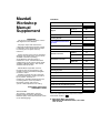
Mazda6
Workshop
Manual
Supplement
FOREWORD
This manual contains on-vehicle service
and diagnosis for the Mazda6.
For proper repair and maintenance,
a thorough familiarization with this manual
is important, and it should always be kept
in a handy place for quick and easy
reference.
All the contents of this manual, including
drawings and specifications, are the latest
available at the time of printing.
As modifications affecting repair or
maintenance occur, relevant information
supplementary to this volume will be made
available at Mazda dealers. This manual
should be kept up-to-date.
Mazda Motor Corporation reserves
the right to alter the specifications and
contents of this manual without obligation
or advance notice.
All rights reserved. No part of this book
may be reproduced or used in any form or
by any means, electronic or
mechanical—including photocopying and
recording and the use of any kind of
information storage and retrieval
system—without permission in writing.
Mazda Motor Corporation
HIROSHIMA, JAPAN
APPLICATION:
This manual is applicable to vehicles
beginning with the Vehicle Identification
Numbers (VIN), and related materials shown
on the following page.
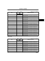
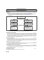
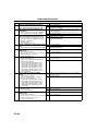
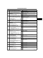
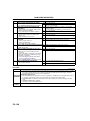
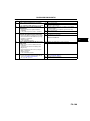
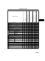
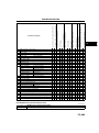
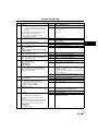
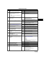
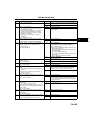
CONTENTS
Title
Section
General Information
GI
L8, LF, L3
B1
MZR–CD (RF Turbo)
B2
Engine
Lubrication System
D
Cooling System
E
Fuel and Emission Control
Systems
L8, LF, L3
F1
MZR–CD (RF Turbo)
F2
Engine Electrical System
G
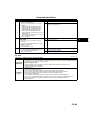
Clutch
H
G35M–R
J1
A65M–R
J2
FN4A–EL
K1
JA5AX–EL
K2
Manual Transaxle
Automatic Transaxle
Propeller Shaft
L
Front and Rear Axles
M
Steering System
N
Braking System
P
Suspension
R
Body
S
Body Electrical System
T
Heater and Air Conditioner Systems
U
Technical Data
TD
Special Tools
ST
There are explanation given only for the sections
marked with shadow (
).
© 2003 Mazda Motor Corporation
PRINTED IN THE NETHERLANDS, JULY 2003
1789–1E–03G
VEHICLE IDENTIFICATION NUMBERS (VIN)
European (L.H.D. U.K.) specs.
JMZ GG12R20# 100001—
JMZ GG12T20#
100001—
JMZ GG14R20# 100001—
JMZ GG14T20#
100001—
JMZ GY19R20#
100001—
JMZ GY19T20#
100001—
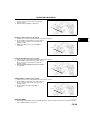
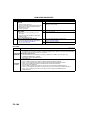
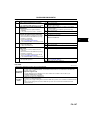
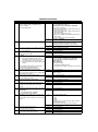
RELATED MATERIALS
Mazda6 Training Manual
(European (L.H.D. U.K.), GCC specs.) . . . . . . . . . . . .
Mazda6 Workshop Manual
(European (L.H.D. U.K.), GCC specs.) . . . . . . . . . . . .
Mazda6 Workshop Manual Supplement
(European (L.H.D. U.K.), GCC specs.) . . . . . . . . . . . .
Mazda6 Workshop Manual Supplement
(European (L.H.D. U.K.), GCC specs.) . . . . . . . . . . . .
Engine Workshop Manual MZR–CD (RF Turbo) . . . . .
Manual Transaxle Workshop Manual A65M–R . . . . . .
Mazda6 Wiring Diagram
(European (L.H.D.), GCC specs.) . . . . . . . . . . . . . . . .
Mazda6 Wiring Diagram Supplement
(European (L.H.D.), GCC specs.) . . . . . . . . . . . . . . . .
Mazda6 Wiring Diagram
(U.K. specs.) . . . . . . . . . . . . . . . . . . . . . . . . . . . . . . . . .
Mazda6 Wiring Diagram Supplement
(U.K. specs.) . . . . . . . . . . . . . . . . . . . . . . . . . . . . . . . . .
Mazda6 Bodyshop Manual
(European (L.H.D. U.K.), GCC specs.) . . . . . . . . . . . .
Mazda6 Bodyshop Manual Supplement Wagon
(European (L.H.D. U.K.), Australian,
General (L.H.D. R.H.D.) specs.). . . . . . . . . . . . . . . . . .
EOBD Training Manual
(General (L.H.D. R.H.D.) specs.) . . . . . . . . . . . . . . . . .
* : Indicates the printing location
E: Europe
0: Japan
3359–1*–02C
1730–1*–02C
1749–1*–02G
1776–10–03G
1744–1E–02D
1739–1E–02D
5558–1*–02G
5575–10–03A
5559–1*–02G
5576–10–03A
3360–1*–02C
3368–1*–02I
3345–1*–00B
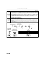
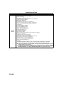
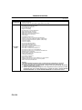
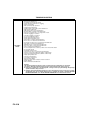
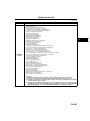
WARNING
Servicing a vehicle can be dangerous. If you have not received
service-related training, the risks of injury, property damage, and
failure of servicing increase. The recommended servicing procedures
for the vehicle in this workshop manual were developed with
Mazda-trained technicians in mind. This manual may be useful to
non-Mazda trained technicians, but a technician with our
service-related training and experience will be at less risk when
performing service operations. However, all users of this manual are
expected to at least know general safety procedures.
This manual contains "Warnings" and "Cautions" applicable to risks
not normally encountered in a general technician's experience.
They should be followed to reduce the risk of injury and the risk that
improper service or repair may damage the vehicle or render it unsafe.
It is also important to understand that the "Warnings" and "Cautions"
are not exhaustive. It is impossible to warn of all the hazardous
consequences that might result from failure to follow the procedures.
The procedures recommended and described in this manual are
effective methods of performing service and repair. Some require tools
specifically designed for a specific purpose. Persons using procedures
and tools which are not recommended by Mazda Motor Corporation
must satisfy themselves thoroughly that neither personal safety nor
safety of the vehicle will be jeopardized.
The contents of this manual, including drawings and specifications, are
the latest available at the time of printing, and Mazda Motor Corporation
reserves the right to change the vehicle designs and alter the contents
of this manual without notice and without incurring obligation.
Parts should be replaced with genuine Mazda replacement parts or
with parts which match the quality of genuine Mazda replacement
parts. Persons using replacement parts of lesser quality than that of
genuine Mazda replacement parts must satisfy themselves thoroughly
that neither personal safety nor safety of the vehicle will be
jeopardized.
Mazda Motor Corporation is not responsible for any problems which
may arise from the use of this manual. The cause of such problems
includes but is not limited to insufficient service-related training, use of
improper tools, use of replacement parts of lesser quality than that of
genuine Mazda replacement parts, or not being aware of any revision
of this manual.
GI
GENERAL INFORMATION
GI
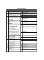
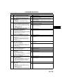
HOW TO USE THIS MANUAL ............................. GI-2
RANGE OF TOPICS .......................................... GI-2
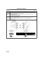
VIN CODE ............................................................. GI-3
VIN CODE.......................................................... GI-3
NEW STANDARDS .............................................. GI-4
NEW STANDARDS TABLE ............................... GI-4
ABBREVIATIONS ................................................ GI-6
ABBREVIATIONS TABLE.................................. GI-6
SCHEDULED MAINTENANCE ............................ GI-7
SCHEDULED MAINTENANCE TABLE ............. GI-7
GI–1
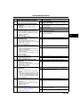
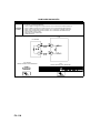
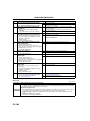
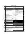
HOW TO USE THIS MANUAL
HOW TO USE THIS MANUAL
RANGE OF TOPICS
B6E201000001101
• This manual indicates only changes/additions, as it is supplemental to the related materials. Therefore it may
not contain the necessary reference service procedures to perform the service indicated in this manual.
End Of Sie
GI–2
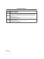
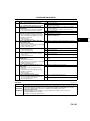
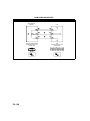
VIN CODE
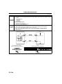
VIN CODE
GI
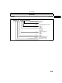
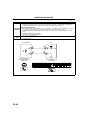
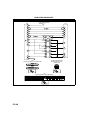
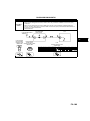
VIN CODE
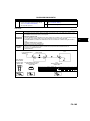
B6E200800021101
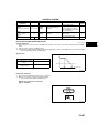
European (L.H.D. U.K.) specs.End Of Sie
J M Z GG 1 2 3 2 0 # 1 2 3 4 5 6
Plant
Dammy
Dammy
For Others (Israel etc.) : Model year
Transaxle
Engine
Body style
Serial No.
0=Hiroshima
1=Hofu
0
3 to 9 (same as Model year-Israel)
3=2003, 4=2004
2=5MTX
5=4ATX
7=5ATX
3=2.3L (L3)
8=1.8L (L8)
F=2.0L (LF)
R=MZR-CD (RF-Turbo)-Hi
T=MZR-CD (RF-Turbo)-Low
2=4SD
4=5HB
9=WAGON
Vehicle type
8=4WD
1=2WD
GG=MAZDA6 (4SD, 5HB)
GY=MAZDA6 (WAGON)
World manufacturer identification
JMZ=Europe (L.H.D. U.K.)
Remarks
B6E2008W001
GI–3
NEW STANDARDS
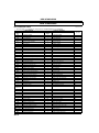
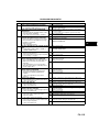
NEW STANDARDS
NEW STANDARDS TABLE
• The following is a comparison of the previous standard and the new standard.
New Standard
Abbreviation
AP
ACL
A/C
BARO
B+
—
—
CMP sensor
CAC
CLS
CTP
—
CPP
CIS
CS sensor
CKP sensor
DLC
DTM
DTC
DI
DLI
EI
ECT
EM
—
EVAP
EGR
FC
FF
4GR
—
FSO
solenoid
GEN
GND
HO2S
IAC
—
—
—
—
IAT
KS
MIL
MAP
MAF sensor
MFI
OBD
GI–4
Name
Accelerator Pedal
Air Cleaner
Air Conditioning
Barometric Pressure
Battery Positive Voltage
Brake Switch
Calibration Resistor
Camshaft Position Sensor
Charge Air Cooler
Closed Loop System
Closed Throttle Position
Closed Throttle Position Switch
Clutch Pedal Position
Continuous Fuel Injection System
Control Sleeve Sensor
Crankshaft Position Sensor
Data Link Connector
Diagnostic Test Mode
Diagnostic Trouble Code
Distributor Ignition
Distributorless Ignition
Electronic Ignition
Engine Coolant Temperature
Engine Modification
Engine Speed Input Signal
Evaporative Emission
Exhaust Gas Recirculation
Fan Control
Flexible Fuel
Fourth Gear
Fuel Pump Relay
B6E202800020101
Previous Standard
Abbreviation
—
—
—
—
VB
—
—
—
—
—
—
—
—
EGI
CSP sensor
—
—
—
—
—
—
—
—
—
—
—
—
—
—
—
—
Name
Remark
Accelerator Pedal
Air Cleaner
Air Conditioning
Atmospheric Pressure
Battery Voltage
Stoplight Switch
Corrected Resistance
Crank Angle Sensor
Intercooler
Feedback System
Fully Closed
Idle Switch
Clutch Position
Electronic Gasoline Injection System
Control Sleeve Position Sensor
Crank Angle Sensor 2
Diagnosis Connector
Test Mode
Service Code(s)
Spark Ignition
Direct Ignition
Electronic Spark Ignition
Water Thermo
Engine Modification
Engine RPM Signal
Evaporative Emission
Exhaust Gas Recirculation
Fan Control
Flexible Fuel
Overdrive
Circuit Opening Relay
#6
#6
#1
#2
#3
Fuel Shut Off Solenoid
FCV
Fuel Cut Valve
#6
Generator
Ground
Heated Oxygen Sensor
Idle Air Control
IDM Relay
Incorrect Gear Ratio
Injection Pump
Input/Turbine Speed Sensor
Intake Air Temperature
Knock Sensor
Malfunction Indicator Lamp
Manifold Absolute Pressure
Mass Air Flow Sensor
Multiport Fuel Injection
On Board Diagnostic
—
—
—
—
—
—
FIP
—
—
—
—
—
—
—
—
Alternator
Ground/Earth
Oxygen Sensor
Idle Speed Control
Spill Valve Relay
With heater
—
Fuel Injection Pump
Pulse Generator
Intake Air Thermo
Knock Sensor
Malfunction Indicator Light
Intake Air Pressure
Airflow Sensor
Multiport Fuel Injection
Diagnosis/Self Diagnosis
#6
#6
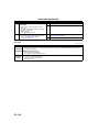
NEW STANDARDS
New Standard
Abbreviation
OL
—
OC
O2S
PNP
—
PSP
PCM
—
PAIR
—
AIR
SAPV
SFI
Name
Open Loop
Output Speed Sensor
Oxidation Catalytic Converter
Oxygen Sensor
Park/Neutral Position
PCM Control Relay
Power Steering Pressure
Powertrain Control Module
Pressure Control Solenoid
Name
Open Loop
Vehicle Speed Sensor 1
Catalytic Converter
Oxygen Sensor
Park/Neutral Range
Main Relay
Power Steering Pressure
Engine Control Unit
Line Pressure Solenoid Valve
Pulsed Secondary Air Injection
—
Secondary Air Injection System
Pump Speed Sensor
—
NE Sensor
Secondary Air Injection
—
Secondary Air Injection System
Secondary Air Pulse Valve
Sequential Multiport Fuel Injection
—
Shift Solenoid A
—
Shift Solenoid B
—
3GR
TWC
TB
TP sensor
TCV
TCC
Previous Standard
Abbreviation
—
—
—
—
—
—
—
ECU
—
Shift Solenoid C
Third Gear
Three Way Catalytic Converter
Throttle Body
Throttle Position Sensor
Timer Control Valve
Torque Converter Clutch
Transmission (Transaxle) Control
TCM
Module
Transmission (Transaxle) Fluid
—
Temperature Sensor
TR
Transmission (Transaxle) Range
TC
Turbocharger
VSS
Vehicle Speed Sensor
VR
Voltage Regulator
VAF sensor Volume Air Flow Sensor
Warm Up Three Way Catalytic
WU-TWC
Converter
WOT
Wide Open Throttle
—
—
—
—
—
—
—
—
—
—
—
TCV
—
Reed Valve
Sequential Fuel Injection
1–2 Shift Solenoid Valve
Shift A Solenoid Valve
2–3 Shift Solenoid Valve
Shift B Solenoid Valve
3–4 Shift Solenoid Valve
3rd Gear
Catalytic Converter
Throttle Body
Throttle Sensor
Timing Control Valve
Lockup Position
—
EC-AT Control Unit
—
ATF Thermosensor
—
—
—
—
—
Inhibitor Position
Turbocharger
Vehicle Speed Sensor
IC Regulator
Airflow Meter
—
Catalytic Converter
—
Fully Open
Remark
GI
#6
#4
Pulsed
injection
#6
Injection
with air
pump
#6
#5
#1 : Diagnostic trouble codes depend on the diagnostic test mode.
#2 : Controlled by the PCM
#3 : In some models, there is a fuel pump relay that controls pump speed. That relay is now called the fuel pump
relay (speed).
#4 : Device that controls engine and powertrain
#5 : Directly connected to exhaust manifold
#6 : Part name of diesel engine
End Of Sie
GI–5
ABBREVIATIONS
ABBREVIATIONS
ABBREVIATIONS TABLE
CAN
IDM
KOEO
KOER
OFF
ON
PID
SW
TCV
VBC
VSC
WDS
End Of Sie
GI–6
Controller Area Network
Injector Driver Module
Key On Engine Off
Key Off Engine Running
Switch Off
Switch On
Parameter Identification
Switch
Timer Control Valve
Variable Boost Control
Variable Swirl Control
Worldwide Diagnostic System
B6E203000011101
SCHEDULED MAINTENANCE
SCHEDULED MAINTENANCE
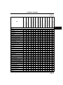
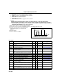
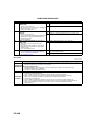
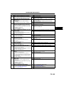
SCHEDULED MAINTENANCE TABLE
GI
B6E203400013101
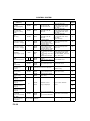
For Europe (L.H.D. U.K.)
Chart symbols:
I : Inspect and clean, repair, adjust, or replace if necessary.
R : Replace
C : Clean
Remarks:
• The ignition and fuel systems are highly important to the emission control system and to efficient engine operation. All
inspections and adjustments must be made by an expert repairer, we recommend an Authorized Mazda Repairer.
• After the described period, continue to follow the described maintenance at the recommended intervals.
• Refer below for a description of items marked* in the maintenance chart.
*1: If the vehicle is operated under any of the following conditions, change the engine oil and oil filter every 10,000 km
(6,250 miles) or shorter.
a. Driving in dusty conditions.
b. Extended periods of idling or low speed operation.
c. Driving for long period in cold temperatures or driving regularly at short distance only.
*2: Also inspect and adjust the power steering and air conditioner drive belts, if installed.
*3: If the brakes are used extensively (for example, continuous hard driving or mountain driving) or if the vehicle is
operated in extremely humid climates, change the brake fluid annually.
*4: If the vehicle is operated in very dusty or sandy areas, clean and if necessary, replace the air cleaner element more
often than the recommended intervals.
*5: Replacement of the timing belt is required at every 100,000 km (62,500 miles).
Failure to replace the timing belt may result in damage to the engine.
*6: Replacement of the timing belt is required at every 120,000 km (75,000 miles).
Failure to replace the timing belt may result in damage to the engine.
*7: If the vehicle is operated under any of the following conditions, change the rear differential oil every 45,000 km (27,000
miles).
a. Towing a trailer or using a car - top carrier
b. Driving in dusty, sandy or wet condition
c. Extended periods of idling or low speed operation
d. Repeated short trips of less than 16 km (10 miles)
*8: If this component has been submerged in water, the oil should be changed.
Maintenance Item
Maintenance Interval (Number of months or km (miles), whichever comes first)
Months
12
24
36
48
60
72
84
96
108
×1000 km
20
40
60
80
100
120
140
160
180
×1000 miles
12.5
25
37.5
50
62.5
75
87.5 100 112.5
GASOLINE ENGINE
Engine valve clearance
Audible inspect every 120,000 km (75,000 miles), if noisy, adjust
Spark plugs
Replace every 100,000 km (62,500 miles)
Air cleaner element
*4
R
R
R
Evaporative system (if installed)
I
I
I
DIESEL ENGINE
Engine valve clearance
I
I
Finland, Sweden, Norway*5
Replace every 100,000 km (62,500 miles)
Engine timing belt
Others*6
Replace every 120,000 km (75,000 miles)
Fuel filter
R
R
R
Fuel injection system
I
I
I
I
Air cleaner element
*4
C
C
R
C
C
R
C
C
R
E.G.R. system
I
I
I
GASOLINE and DIESEL ENGINE
Engine oil
*1
R
R
R
R
R
R
R
R
R
Engine oil filter
*1
R
R
R
R
R
R
R
R
R
Drive belts
*2
I
I
I
Cooling system (including coolant level adjustment)
I
I
I
I
Replace at first 4 years or 100,000 km (62,500 miles);
Engine coolant
after that, every 2 years
GI–7
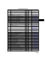
SCHEDULED MAINTENANCE
Maintenance Interval (Number of months or km (miles), whichever comes first)
Months
12
24
36
48
60
72
84
96
108
Maintenance Item
×1000 km
20
40
60
80
100
120
140
160
180
×1000 miles
12.5
25
37.5
50
62.5
75
87.5 100 112.5
Fuel lines & hoses
I
I
I
I
Battery electrolyte level & specific gravity
I
I
I
I
I
I
I
I
I
Brake fluid
*3
R
R
R
R
Brake lines, hoses & connections
I
I
I
I
I
I
I
I
I
Parking brake
I
I
I
I
I
I
I
I
I
Power brake unit & hoses
I
I
I
I
I
I
I
I
I
Disc brakes
I
I
I
I
I
I
I
I
I
Power steering fluid, lines, hoses, and connections
I
I
I
I
I
I
I
I
I
Steering operation & linkages
I
I
I
I
Manual transaxle oil
R
Automatic transaxle fluid level
I
I
I
*7*8
Rear differential oil (for 4WD)
*8
Transfer oil (for 4WD)
Front & rear suspension & ball joints
Drive shaft dust boots
Exhaust system and heat shields
Cabin air filter (if installed) (pollen filter)
Body condition
(for rust, corrosion & perforation)
Tires (including spare tyre)
(with inflation pressure adjustment)
I
I
I
I
I
R
R
I
I
I
I
I
R
R
Inspect annually
I
I
I
I
I
I
I
I
I
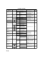
Scheduled Maintenance Service (Specific Work Required)
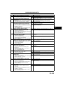
• The specific work required for each maintenance item is listed in the following table. (Please refer to the section
applicable to the model serviced.)
For Europe (L.H.D. U.K.)
Bold frames: New item
Maintenance Item
ENGINE
Engine valve clearance
Drive belts
Engine timing belt
Engine oil
Oil filter
COOLING SYSTEM
Cooling system
(including coolant level adjustment)
Engine coolant
FUEL SYSTEM
Air cleaner element
Fuel filter
Fuel lines & hoses
Fuel injection system (for MZR-CD (RF Turbo))
IGNITION SYSTEM (FOR GASOLINE)
Spark plugs
Specific Work Required
Measure clearance
Inspect for wear, cracks and fraying, and check tension.
Replace drive belt.
Replace engine timing belt.
Replace engine oil and inspect for leakage.
Replace oil filter and inspect for leakage.
Check coolant level and quality, and inspect for leakage.
Replace coolant.
Inspect for dirt, oil and damage.
Clean air cleaner element (by blowing air).
Replace air cleaner element.
Replace fuel filter.
Inspect for cracks, leakage and loose connection.
Update to injection amount correction with WDS. (see W/M)
Inspect for wear, damage, carbon, high-tension lead condition and measure
plug gap.
Replace spark plugs.
EMISSION CONTROL SYSTEM
Evaporative system (for gasoline)
E.G.R. system (MZR-CR (RF Turbo))
GI–8
Check system operation (see W/M), vapor lines, vacuum fitting hoses and
connection.
Check system operation (see W/M), vacuum fitting hoses and connection.
Update to MAF correction for E.G.R control with WDS. (see W/M)
SCHEDULED MAINTENANCE
Maintenance Item
ELECTRICAL SYSTEM
Battery electrolyte level & specific gravity
CHASSIS & BODY
Brake fluid
Brake lines, hoses & connections
Parking brake
Power brake unit & hoses
Disc brakes
Power steering fluid & lines
Power steering fluid
Power steering system & hoses
Steering operation & gear housing
Steering linkages tie rod ends & arms
Front & rear suspension ball joints
Manual transmission/transaxle oil
Automatic transmission/transaxle fluid level
Rear differential oil
Transfer oil (for 4×4)
Drive shaft dust boots
Body condition
(for rust, corrosion & perforation)
Exhaust system and heat shields
Tires
(including spare tire)
(with inflation pressure adjustment)
AIR CONDITIONER SYSTEM (IF EQUIPPED)
Cabin air filter
Specific Work Required
Check level and specific gravity.
GI
Check fluid level and inspect for leakage.
Replace brake fluid.
Inspect for cracks, damage, chafing, corrosion, scars, swelling and fluid
leakage.
Check lever stroke.
Check vacuum lines, connections and check valve for improper attachment,
air tightness, cracks chafing and deterioration.
Test for judder and noise. Inspect caliper for correct operation and fluid
leakage, brake pads for wear. Check disc plate condition and thickness.
Check fluid level and lines for improper attachment, leakage, cracks,
damage, loose connections, chafing and deterioration.
Check fluid level.
Check lines for improper attachment, leakage, cracks, damage, loose
connections, chafing and deterioration.
Check that the steering wheel has the specified play. Be sure to check for
changes, such as excessive play, hard steering or strange noises.
Check gear housing and boots for looseness, damage and grease/gear oil
leakage.
Check ball joint, dust cover and other components for looseness, wear,
damage and grease leakage.
Inspect for grease leakage, cracks, damage and looseness.
Check oil level and inspect for leakage.
Replace manual transmission/transaxle oil.
Check fluid level.
Check oil level and inspect for leakage.
Replace rear differential oil.
Check oil level and inspect for leakage.
Replace transfer oil.
Inspect for grease leakage, cracks, damage and looseness.
Inspect body surface for paint damage, rust, corrosion and perforation.
Inspect for damage, corrosion, looseness of connections and gas leakage.
Check air pressure and inspect tires for tread wear, damage and cracks;
and wheels for damage and corrosion.
Replace cabin air filter.
End Of Sie
GI–9
FUEL AND EMISSION CONTROL SYSTEMS
[MZR-CD (RF Turbo)]
F2
FEATURES
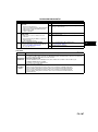
OUTLINE .............................................................. F2-3
OUTLINE OF CONSTRUCTION ....................... F2-3
FEATURES ........................................................ F2-3
SPECIFICATIONS ............................................. F2-3
CONTROL SYSTEM DIAGRAM........................ F2-4
CONTROL SYSTEM WIRING DIAGRAM.......... F2-6
CONTROL SYSTEM........................................... F2-10
CONTROL SYSTEM OUTLINE ....................... F2-10
STRUCTURAL VIEW....................................... F2-13
BLOCK DIAGRAM ........................................... F2-15
CONTROL DEVICE AND CONTROL
RELATIONSHIP CHART .............................. F2-17
ON-BOARD DIAGNOSTIC................................. F2-18
ON-BOARD DIAGNOSTIC OUTLINE.............. F2-18
DIAGNOSTIC TEST MODE............................. F2-18
DTC DETECTION LOGIC AND
CONDITIONS ............................................... F2-21
PID/DATA MONITOR AND RECORD ............. F2-26
SIMULATION TEST ......................................... F2-28
SERVICE
OUTLINE ............................................................ F2-30
SUPPLEMENTAL SERVICE
INFORMATION............................................. F2-30
CONTROL SYSTEM........................................... F2-31
PCM INSPECTION .......................................... F2-31
EGR VALVE POSITION SENSOR
INSPECTION ................................................ F2-37
ON-BOARD DIAGNOSTIC................................. F2-38
FOREWORD.................................................... F2-38
OBD PENDING TROUBLE CODES ................ F2-38
OBD FREEZE FRAME DATA.......................... F2-38
OBD READ/CLEAR DIAGNOSTIC
TEST RESULTS ........................................... F2-38
OBD PARAMETER IDENTIFICATION
(PID) ACCESS.............................................. F2-38
ON-BOARD DIAGNOSTIC TEST .................... F2-38
OBD DRIVE MODE ......................................... F2-39
DTC TABLE ..................................................... F2-40
DTC P0016 ...................................................... F2-42
DTC P0045 ...................................................... F2-43
DTC P0088 ...................................................... F2-46
DTC P0093 ...................................................... F2-47
DTC P0096 ...................................................... F2-48
DTC P0097 ...................................................... F2-49
DTC P0098 ...................................................... F2-51
DTC P0101 ...................................................... F2-54
DTC P0102 ...................................................... F2-55
DTC P0103 ...................................................... F2-58
DTC P0106 ...................................................... F2-60
DTC P0107 ...................................................... F2-61
DTC P0108 ...................................................... F2-64
DTC P0111 ...................................................... F2-66
DTC P0112 ...................................................... F2-67
DTC P0113 ...................................................... F2-69
DTC P0116 ...................................................... F2-72
DTC P0117 ...................................................... F2-74
DTC P0118 ...................................................... F2-75
DTC P0122 ...................................................... F2-78
DTC P0123 ...................................................... F2-80
DTC P0182 ...................................................... F2-82
DTC P0183 ...................................................... F2-84
DTC P0191 ...................................................... F2-86
DTC P0192 ...................................................... F2-87
DTC P0193 ...................................................... F2-90
DTC P0200 ...................................................... F2-92
DTC P0201 ...................................................... F2-95
DTC P0202 ...................................................... F2-98
DTC P0203 .................................................... F2-101
DTC P0204 .................................................... F2-104
DTC P0222 .................................................... F2-107
DTC P0223 .................................................... F2-110
DTC P0225 .................................................... F2-112
DTC P0301, P0302, P0303, P0304 ............... F2-114
DTC P0336 .................................................... F2-116
DTC P0337 .................................................... F2-117
DTC P0341 .................................................... F2-120
DTC P0342 .................................................... F2-121
DTC P0401 .................................................... F2-124
DTC P0402 .................................................... F2-125
DTC P0404 .................................................... F2-126
DTC P0406 .................................................... F2-127
DTC P0489 .................................................... F2-130
DTC P0490 .................................................... F2-132
DTC P0500 .................................................... F2-134
DTC P0504 .................................................... F2-134
DTC P0512 .................................................... F2-137
DTC P0562 .................................................... F2-140
DTC P0563 .................................................... F2-141
DTC P0564 .................................................... F2-144
DTC P0602 .................................................... F2-146
DTC P0606 .................................................... F2-146
DTC P0610 .................................................... F2-147
DTC P0627 .................................................... F2-147
DTC P0628 .................................................... F2-150
DTC P0629 .................................................... F2-152
DTC P0661 .................................................... F2-154
DTC P0662 .................................................... F2-156
DTC P0664 .................................................... F2-158
DTC P0665 .................................................... F2-160
DTC P0704 .................................................... F2-162
DTC P0850 .................................................... F2-164
DTC P1190 .................................................... F2-166
DTC P1211 .................................................... F2-169
DTC P1391 .................................................... F2-170
DTC P1392 .................................................... F2-173
DTC P2009 .................................................... F2-176
DTC P2010 .................................................... F2-178
DTC P2135 .................................................... F2-180
DTC P2136 .................................................... F2-180
DTC P2141 .................................................... F2-182
F2–1
F2
DTC P2142 .................................................... F2-185
DTC P2144 .................................................... F2-187
DTC P2145 .................................................... F2-189
DTC P2146 .................................................... F2-191
DTC P2149 .................................................... F2-194
DTC P2227 .................................................... F2-197
DTC P2228 .................................................... F2-197
DTC P2229 .................................................... F2-198
TROUBLESHOOTING...................................... F2-200
SYMPTOM QUICK DIAGNOSIS CHART ...... F2-200
NO.5 ENGINE STALLS-AFTER
START/AT IDLE.......................................... F2-205
NO.6 CRANKS NORMALLY BUT WILL
NOT START................................................ F2-209
NO.8 ENGINE RUNS ROUGH/ROLLING
IDLE ............................................................ F2-212
NO.10 LOW IDLE/STALLS DURING
DECELERATION ........................................ F2-214
NO.11 ENGINE STALLS/QUITS, ENGINE
RUNS ROUGH, MISSES, BUCK/LERK,
HESITATION/STUMBLE............................. F2-217
NO.12 LACK/LOSS OF POWERACCELERATION/CRUISE.......................... F2-220
NO.13 KNOCKING/PINGING ........................ F2-224
NO.15 EMISSION COMPLIANCE ................. F2-227
NO.19 EXCESSIVE BLACK SMOKE............. F2-230
ENGINE CONTROL SYSTEM OPERATION
INSPECTION .............................................. F2-232
F2–2
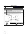
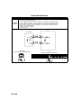
OUTLINE
OUTLINE
OUTLINE OF CONSTRUCTION
B6E400218881101
• The fuel and emission control system is essentially carried over from that of the previous Mazda6 (GG, GY)
MZR-CD (RF Turbo) engine models, except for the following features. (See Mazda6 Workshop Manual
Supplement 1749-1*-02G.)
End Of Sie
FEATURES
B6E400218881102
Improved Emission Performance
• A EGR valve position sensor has been adopted.
Improved Serviceability
• The number of DTCs has been increased to provide more detail information.
• The DTC troubleshooting procedures have been renewed due to the adoption of the diagnostic test mode and
OBD drive mode.
• The PID item has been added.
• The simulation item has been added.
End Of Sie
SPECIFICATIONS
B6E400218881103
Item
Air cleaner element
Supercharger
Glow plug
Pump
Fuel tank
Catalyst
EGR control
PCV system
Type
Type
Type
Type
Capacity
(L {US gal, lmp gal})
Type
Type
Type
New Mazda6 (GG, GY)
Previous Mazda6 (GG, GY)
MZR-CD (RF Turbo)
Non woven fabric (dry)
Turbocharger
Metal
Supply pump
64 {17, 14}
Warm up oxidation catalyst, Oxidation catalyst
Duty control
Closed
End Of Sie
F2–3
F2
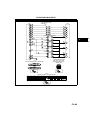
OUTLINE
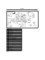
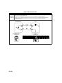
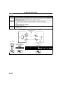
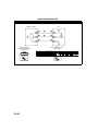
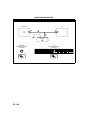
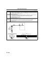
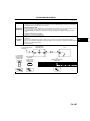
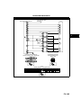
CONTROL SYSTEM DIAGRAM
B6E400218881104
.
47 48 49 50 51 52 53
56
5
17
B
45
11 10
9
15
46
A
43
44
3
16
6
* 55
12
13
18
19
34
1
14
25
24
23
8
30
26
31
33
A
32
21
7
35
29 28 20
27
2
4
36
42
B
37
39
41
38
22
54
57
40
B6E4002W002
1
2
3
4
5
6
7
8
9
10
11
12
13
14
15
16
17
18
19
20
21
22
23
24
25
26
27
28
29
30
Air cleaner
Vacuum chamber
VBC check valve
MAF/IAT sensor
VBC solenoid valve
Vacuum damper
Guide blade actuator
Turbocharger
Charge air cooler
IAT sensor No.2
Boost sensor
Intake shutter valve actuator
Intake shutter solenoid valve (half)
Intake shutter solenoid valve (full)
EGR solenoid valve (vacuum)
EGR solenoid valve (vent)
EGR control solenoid valve
EGR valve
EGR water cooler
VSC valve actuator
VSC solenoid valve
Fuel tank
Fuel filter
Fuel warmer
Supply pump
Suction control valve
Fuel temperature sensor
Common rail
Fuel pressure sensor
Fuel pressure limiter
F2–4
OUTLINE
31
32
33
34
35
36
37
38
39
40
41
42
43
44
45
46
47
48
49
50
51
52
53
54
55
56
57
Glow plug
Fuel injector
ECT sensor
Calibration resistor
CMP sensor
Warm up oxidation catalytic converter
Oxidation catalytic converter
Silencer
Vacuum pump
CKP sensor
Idle switch
APP sensor
Glow plug relay
IDM
PCM
BARO sensor
PCM control relay
Engine switch
Starter (starter signal)
Neutral switch
Clutch switch
A/C switch
CAN bus
To PCM
EGR valve position sensor
DLC-2
Fuel flow
F2
End Of Sie
F2–5
OUTLINE
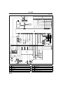
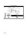
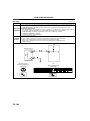
CONTROL SYSTEM WIRING DIAGRAM
B6E400218881105
3
6
4
1A 1B 1C 1D 1E 1F 1G 1H
2A 2B 2C 2D 2E 2F 2G 2H
1A 1B 1C 1D 1E 1F
a
b
c
d
2
5
e
f
g
30 42 44 45 43
13 39
1
57
78
56
33
80 28
4
27
7 34 64 104 103 85 65 91 69 53 79
1
9 14 60
h
i
j
k
C E
9
17
E C
D A
15
16
A
A C B D
E
D
22
23
l
m
n
o
8
21
B ACC IG2 IG1 ST
LOCK
ACC
ON
ST
20
14
18
19
A
7
A
B
10
M
P D
11
A
12
A
B
13
A6E40022002
.
1
2
3
4
5
6
PCM
DLC-2
Water heater unit
Fuel pump
Other unit
IDM
F2–6
7
8
9
10
11
12
Battery
Engine switch
Starter relay
Starter
Generator
Oil pressure switch
OUTLINE
13
14
15
16
17
18
19
20
21
22
23
Sedimentor switch
Instrument cluster
Neutral switch
Clutch switch
Coil
Brake switch
Brake switch 2
Cruise control switch
With cruise control system
PCM control relay
MAF/IAT sensor
F2
F2–7
OUTLINE
.
25
24
26
A C B D
28
27
A C B D
29
30
A C B D
31
A C B D
32
33
A B
A B
81 55
29 3
a
b
c
d
C
34
35
36
37
38
39
40
A B
A B
A B
A B
A B
A B
A B
99
72
74
100
67
77
e
f
g
62
37
89
11
101
1
36
10
88
31
90 61
94 93 32
35
87
76 84
8
102
86 68
73
h
i
j
k
C
A
C
C
B
A
A
A
B A
A
B
B
B
A
B
B
B
60
D
C A
A
48
B D C
61
44
45
46
47
65
43
41
42
l
m
n
o
59
64
C
E
49
B
A
D A
56
54
62
57
51
50
63
M
52
53
58
M
55
M
B6E4002W001
24
25
26
27
28
29
Calibration resistor No.1
Fuel injector No.1
Calibration resistor No.2
Fuel injector No.2
Calibration resistor No.3
Fuel injector No.3
F2–8
OUTLINE
30
31
32
33
34
35
36
37
38
39
40
41
42
43
44
45
46
47
48
49
50
51
52
53
54
55
56
57
58
59
60
61
62
63
64
65
Calibration resistor No.4
Fuel injector No.4
CMP sensor
CKP sensor
EGR solenoid valve (vacuum)
EGR solenoid valve (vent)
VSC solenoid valve
Intake shutter solenoid valve (half)
Intake shutter solenoid valve (full)
VBC solenoid valve
EGR control solenoid valve
Boost sensor
APP sensor
Idle switch
Fuel pressure sensor
ECT sensor
Fuel temperature sensor
Suction control valve
IAT sensor No.2
Cooling fan relay No.2
Cooling fan No.1
Refrigerant pressure switch (middle)
A/C switch
A/C amplifier
Cooling fan relay No.1
Cooling fan No.2
A/C relay
Refrigerant pressure switch (HI and LO)
Magnetic clutch
With A/C
Glow plug relay
Glow plug
Vacuum switch
Fuel warmer
With fuel warmer
EGR valve position sensor
F2
End Of Sie
F2–9
CONTROL SYSTEM
CONTROL SYSTEM
CONTROL SYSTEM OUTLINE
B6E404018881101
• The control system is essentially carried over from that of the previous Mazda6 (GG, GY) MZR-CD (RF Turbo)
engine models. (See Mazda6 Workshop Manual Supplement 1749-1*-02G.)
Input Device
×:Applicable –: Not applicable
Item
New
Previous
Mazda6
Mazda6
(GG, GY) (GG, GY)
MZR-CD (RF Turbo)
Battery
×
Starter (starter signal)
×
Starter relay
×
Clutch switch
×
Neutral switch
×
Brake switch
×
Idle switch
×
A/C switch
×
Refrigerant pressure switch
×
Cruise control switch
×
Accelerator position sensor
×
MAF/IAT sensor
×
IAT sensor No.2
×
ECT sensor
×
Fuel temperature sensor
×
BARO sensor (integrated in PCM)
×
Boost sensor
×
Fuel pressure sensor
×
CMP sensor
×
CKP sensor
×
VSS
×
Calibration resistor
×
Immobilizer unit (integrated in
PCM)
×
EGR valve position sensor
F2–10
×
–
Remark for new model
Same function as previous Mazda6 (GG, GY) MZR-CD (RF
Turbo) engine model
Same function as previous Mazda6 (GG, GY) MZR-CD (RF
Turbo) engine model
Same function as previous Mazda6 (GG, GY) MZR-CD (RF
Turbo) engine model
Same function as previous Mazda6 (GG, GY) MZR-CD (RF
Turbo) engine model
Same function as previous Mazda6 (GG, GY) MZR-CD (RF
Turbo) engine model
Same function as previous Mazda6 (GG, GY) MZR-CD (RF
Turbo) engine model
Same function as previous Mazda6 (GG, GY) MZR-CD (RF
Turbo) engine model
Same function as previous Mazda6 (GG, GY) MZR-CD (RF
Turbo) engine model
Same function as previous Mazda6 (GG, GY) MZR-CD (RF
Turbo) engine model
Same function as previous Mazda6 (GG, GY) MZR-CD (RF
Turbo) engine model
Same function as previous Mazda6 (GG, GY) MZR-CD (RF
Turbo) engine model
Same function as previous Mazda6 (GG, GY) MZR-CD (RF
Turbo) engine model
Same function as previous Mazda6 (GG, GY) MZR-CD (RF
Turbo) engine model
Same function as previous Mazda6 (GG, GY) MZR-CD (RF
Turbo) engine model
Same function as previous Mazda6 (GG, GY) MZR-CD (RF
Turbo) engine model
Same function as previous Mazda6 (GG, GY) MZR-CD (RF
Turbo) engine model
Same function as previous Mazda6 (GG, GY) MZR-CD (RF
Turbo) engine model
Same function as previous Mazda6 (GG, GY) MZR-CD (RF
Turbo) engine model
Same function as previous Mazda6 (GG, GY) MZR-CD (RF
Turbo) engine model
Same function as previous Mazda6 (GG, GY) MZR-CD (RF
Turbo) engine model
Same function as previous Mazda6 (GG, GY) MZR-CD (RF
Turbo) engine model
Same function as previous Mazda6 (GG, GY) MZR-CD (RF
Turbo) engine model
Same function as previous Mazda6 (GG, GY) MZR-CD (RF
Turbo) engine model
Same function as previous Mazda PREMACY (CP) RF Turbo
engine model
CONTROL SYSTEM
Output Device
×:Applicable –: Not applicable
Item
New
Previous
Mazda6
Mazda6
(GG, GY) (GG, GY)
MZR-CD (RF Turbo)
Suction control valve
×
IDM
×
VSC solenoid valve
×
VBC solenoid valve
×
EGR control solenoid valve
×
EGR solenoid valve (vacuum)
×
EGR solenoid valve (vent)
×
Intake shutter solenoid valve (half)
×
Intake shutter solenoid valve (full)
×
Glow indicator light
×
Cruise main indicator light
×
Cruise set indicator light
×
Glow plug relay
×
Cooling fan relay No.1
×
Cooling fan relay No.2
×
A/C relay
×
Remark for new model
Same function as previous Mazda6 (GG, GY) MZR-CD (RF
Turbo) engine model
Same function as previous Mazda6 (GG, GY) MZR-CD (RF
Turbo) engine model
Same function as previous Mazda6 (GG, GY) MZR-CD (RF
Turbo) engine model
Same function as previous Mazda6 (GG, GY) MZR-CD (RF
Turbo) engine model
Same function as previous Mazda6 (GG, GY) MZR-CD (RF
Turbo) engine model
Same function as previous Mazda6 (GG, GY) MZR-CD (RF
Turbo) engine model
Same function as previous Mazda6 (GG, GY) MZR-CD (RF
Turbo) engine model
Same function as previous Mazda6 (GG, GY) MZR-CD (RF
Turbo) engine model
Same function as previous Mazda6 (GG, GY) MZR-CD (RF
Turbo) engine model
Same function as previous Mazda6 (GG, GY) MZR-CD (RF
Turbo) engine model
Same function as previous Mazda6 (GG, GY) MZR-CD (RF
Turbo) engine model
Same function as previous Mazda6 (GG, GY) MZR-CD (RF
Turbo) engine model
Same function as previous Mazda6 (GG, GY) MZR-CD (RF
Turbo) engine model
Same function as previous Mazda6 (GG, GY) MZR-CD (RF
Turbo) engine model
Same function as previous Mazda6 (GG, GY) MZR-CD (RF
Turbo) engine model
Same function as previous Mazda6 (GG, GY) MZR-CD (RF
Turbo) engine model
Control System
×:Applicable –: Not applicable
Item
New
Previous
Mazda6
Mazda6
(GG, GY) (GG, GY)
MZR-CD (RF Turbo)
Idle speed control
×
Glow control
×
VSC
×
Boost pressure control
×
Fuel injection amount control
×
Fuel injection timing control
×
Multiple fuel injection control
×
Fuel pressure control
×
Remark for new model
Same function as previous Mazda6 (GG, GY) MZR-CD (RF
Turbo) engine model
Same function as previous Mazda6 (GG, GY) MZR-CD (RF
Turbo) engine model
Same function as previous Mazda6 (GG, GY) MZR-CD (RF
Turbo) engine model
Same function as previous Mazda6 (GG, GY) MZR-CD (RF
Turbo) engine model
Same function as previous Mazda6 (GG, GY) MZR-CD (RF
Turbo) engine model
Same function as previous Mazda6 (GG, GY) MZR-CD (RF
Turbo) engine model
Same function as previous Mazda6 (GG, GY) MZR-CD (RF
Turbo) engine model
Same function as previous Mazda6 (GG, GY) MZR-CD (RF
Turbo) engine model
F2–11
F2
CONTROL SYSTEM
Item
New
Previous
Mazda6
Mazda6
(GG, GY) (GG, GY)
MZR-CD (RF Turbo)
EGR control
×
Cruise control system
×
Electrical fan control
×
A/C cut-off control
×
Immobilizer system
×
End Of Sie
F2–12
Remark for new model
Same function as previous Mazda6 (GG, GY) MZR-CD (RF
Turbo) engine model
Same function as previous Mazda6 (GG, GY) MZR-CD (RF
Turbo) engine model
Same function as previous Mazda6 (GG, GY) MZR-CD (RF
Turbo) engine model
Same function as previous Mazda6 (GG, GY) MZR-CD (RF
Turbo) engine model
Same function as previous Mazda6 (GG, GY) MZR-CD (RF
Turbo) engine model
CONTROL SYSTEM
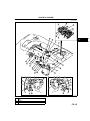
STRUCTURAL VIEW
B6E404018881102
.
35
4
37
33
36
34
23
F2
17
24
2
20
14
40
22
21
18
28
16
11
13
3
29
6
12
26
27
38
31
25
15
39
19
32 30
31
32
19
30
9
9
10
5
5
10
1
8
1
7
8
7
B6E4040W001
1
2
3
PCM (with built-in BARO sensor and immobilizer
unit)
Battery
Starter
F2–13
CONTROL SYSTEM
4
5
6
7
8
9
10
11
12
13
14
15
16
17
18
19
20
21
22
23
24
25
26
27
28
29
30
31
32
33
34
35
36
37
38
39
40
Starter relay
Clutch switch
Neutral switch
Brake switch
Idle switch
Cruise control switch
Accelerator position sensor
MAF/IAT sensor
IAT sensor No.2
ECT sensor
Fuel temperature sensor
Boost sensor
Fuel pressure sensor
CMP sensor
CKP sensor
VSS
Calibration resistor
Suction control valve
IDM
VSC solenoid valve
VBC solenoid valve
EGR control solenoid valve
EGR solenoid valve (vacuum)
EGR solenoid valve (vent)
Intake shutter solenoid valve (half)
Intake shutter solenoid valve (full)
Glow indicator light
Cruise main indicator light
Cruise set indicator light
Glow plug relay
Cooling fan relay No.1
Cooling fan relay No.2
A/C relay
PCM control relay
L.H.D.
R.H.D.
EGR valve position sensor
End Of Sie
F2–14
CONTROL SYSTEM
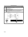
BLOCK DIAGRAM
B6E404018881103
.
1
15
38
2
16
39
17
3
18
40
19
4
41
20
5
21
42
22
43
6
23
44
24
7
25
45
26
8
46
27
9
28
47
29
10
30
CRUISE
MAIN
48
CRUISE
49
31
11
32
50
33
12
34
51
13
35
52
36
37
14
53
54
B6E4040W002
1
2
PCM
Idle speed control
F2–15
F2
CONTROL SYSTEM
3
4
5
6
7
8
9
10
11
12
13
14
15
16
17
18
19
20
21
22
23
24
25
26
27
28
29
30
31
32
33
34
35
36
37
38
39
40
41
42
43
44
45
46
47
48
49
50
51
52
53
54
Glow control
VSC
Boost pressure control
Fuel injection amount control
Fuel injection timing control
Multiple fuel injection control
Fuel pressure control
EGR control
Cruise control system
Electrical fan control
A/C cut-off control
Immobilizer system
Battery
Starter (starter signal)
Starter relay
Clutch switch
Neutral switch
Brake switch
Idle switch
A/C switch
Refrigerant pressure switch
Cruise control switch
Accelerator position sensor
MAF/IAT sensor
IAT sensor No.2
ECT sensor
Fuel temperature sensor
BARO sensor (integrated in PCM)
Boost sensor
Fuel pressure sensor
CMP sensor
CKP sensor
VSS
Calibration resistor
Immobilizer unit (integrated in PCM)
Suction control valve
IDM
VSC solenoid valve
VBC solenoid valve
EGR control solenoid valve
EGR solenoid valve (vacuum)
EGR solenoid valve (vent)
Intake shutter solenoid valve (half)
Intake shutter solenoid valve (full)
Glow indicator light
Cruise main indicator light
Cruise set indicator light
Glow plug relay
Cooling fan relay No.1
Cooling fan relay No.2
A/C relay
EGR valve position sensor
End Of Sie
F2–16
CONTROL SYSTEM
CONTROL DEVICE AND CONTROL RELATIONSHIP CHART
B6E404018881104
Input device
Battery
Starter (starter signal)
Starter relay
Clutch switch
Neutral switch
Brake switch
Idle switch
A/C switch
Refrigerant pressure switch
Cruise control switch
Accelerator position sensor
MAF/IAT sensor
IAT sensor No.2
ECT sensor
Fuel temperature sensor
BARO sensor (integrated in PCM)
Boost sensor
Fuel pressure sensor
CMP sensor
CKP sensor
VSS
Calibration resistor
Immobilizer unit (integrated in PCM)
EGR valve position sensor
Output device
Suction control valve
IDM
VSC solenoid valve
VBC solenoid valve
EGR control solenoid valve
EGR solenoid valve (vacuum)
EGR solenoid valve (vent)
Intake shutter solenoid valve (half)
Intake shutter solenoid valve (full)
Glow indicator light
Cruise main indicator light
Cruise set indicator light
Glow plug relay
Cooling fan relay No.1
Cooling fan relay No.2
A/C relay
Immobilizer system
A/C cut-off control
Electrical fan control
Cruise control system
EGR control
Fuel pressure control
Multiple fuel injection control
Fuel injection timing control
Fuel injection amount control
Boost pressure control
VSC
Glow control
Item
Idle speed control
×: Applicable
F2
×
×
×
×
×
×
×
×
×
×
×
×
×
×
×
×
×
×
×
×
×
×
×
×
×
×
×
×
×
×
×
×
×
×
×
×
×
×
×
×
×
×
×
×
×
×
×
×
×
×
×
×
×
×
×
×
×
×
×
×
×
×
×
×
×
×
×
×
×
×
×
×
×
×
×
×
×
×
×
×
×
×
×
×
×
×
×
×
×
×
×
×
×
×
×
×
×
×
×
×
×
×
×
×
×
×
×
×
×
×
×
×
×
×
×
×
×
×
×
×
×
×
×
×
×
×
×
×
×
×
×
×
×
×
×
×
×
×
×
×
×
×
End Of Sie
F2–17
ON-BOARD DIAGNOSTIC
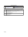
ON-BOARD DIAGNOSTIC
ON-BOARD DIAGNOSTIC OUTLINE
B6E407000102101
Features
•
•
•
•
•
To meet the EOBD regulations
Improved serviceability
Diagnostic test modes adopted
DTC troubleshooting modified
PID/DATA monitor items added
Simulation items added
OBD drive mode adopted
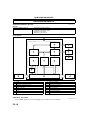
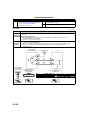
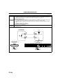
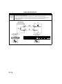
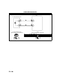
Block Diagram
1
2
3
4
7
5
6
8
9
10
11
12
13
14
15
16
BHE0102T001
.
1
2
3
4
5
6
7
8
PCM
OBD system
Malfunction indication function
MIL
Memory function
Tester communication function
DLC-2
CAN
9
10
11
12
13
14
15
16
WDS or equivalent
Detection function
PID data monitor function
Simulation test function
Fail-safe function
Input device
Engine control system
Output device
End Of Sie
DIAGNOSTIC TEST MODE
• To meet EOBD regulations, the following diagnostic test modes have been adopted.
F2–18
B6E407000102102
ON-BOARD DIAGNOSTIC
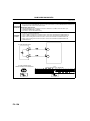
Diagnostic test mode
Mode 01
Mode 02
Mode 03
Mode 04
Mode 07
Mode 09
Item
Sending diagnostic data (PID data monitor/On-board system readiness test)
Sending freeze frame data
Sending emission-related malfunction code (DTC)
Clearing/resetting emission-related malfunction information
Sending continuous monitoring system test results (pending code)
Request vehicle information
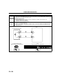
Sending Diagnostic Data
PID data monitor
• The PID data monitor items are shown below.
PID data monitor table
—: Not applicable
Full names
Monitor status since DTCs cleared
Calculated LOAD value
Engine coolant temperature
Intake manifold absolute pressure
Engine speed
Vehicle speed
Intake air temperature
Air flow rate from mass air flow sensor
OBD requirement according to vehicle design
Distance travelled while MIL is activated
Fuel rail pressure
Unit
—
%
°C
F2
°F
kPa
rpm
km/h
°C
mph
°F
g/s
—
km
miles
kPa
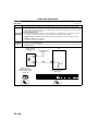
Sending Freeze Frame Data
• The Freeze Frame Data monitor items are shown below.
Freeze Frame Data monitor table
—: Not applicable
Full names
DTC that caused required Freeze Frame Data storage
Calculated LOAD value
Engine coolant temperature
Intake manifold absolute pressure
Engine speed
Vehicle speed
Intake air temperature
Air flow rate from mass air flow sensor
Fuel rail pressure
Unit
—
%
°C
°F
kPa
rpm
km/h
°C
mph
°F
g/s
kPa
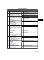
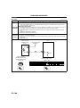
Sending Emission-related Malfunction Code
• The DTCs are shown below.
F2–19
ON-BOARD DIAGNOSTIC
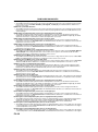
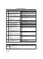
DTC Table
DTC No.
P0016
P0045
P0088
P0093
P0096
P0097
P0098
P0101
P0102
P0103
P0106
P0107
P0108
P0111
P0112
P0113
P0116
P0117
P0118
P0122
P0123
P0182
P0183
P0191
P0192
P0193
P0200
P0201
P0202
P0203
P0204
P0222
P0223
P0225
P0301
P0302
P0303
P0304
P0336
P0337
P0341
P0342
P0401
P0402
P0404
P0406
P0489
P0490
P0500
P0504
P0512
P0562
P0563
F2–20
Condition
Crankshaft position-camshaft position correlation malfunction
Variable boost control (VBC) solenoid valve control circuit low input
Fuel pressure system too high
Fuel system leak detection
Intake air temperature (IAT) sensor No.2 range/performance problem
Intake air temperature (IAT) sensor No.2 circuit low input
Intake air temperature (IAT) sensor No.2 circuit high input
Mass air flow (MAF) sensor range/performance problem
Mass air flow (MAF) sensor circuit low input
Mass air flow (MAF) sensor circuit high input
Boost sensor range/performance problem
Boost sensor circuit low input
Boost sensor circuit high input
Intake air temperature (IAT) sensor No.1 range/performance problem
Intake air temperature (IAT) sensor No.1 circuit low input
Intake air temperature (IAT) sensor No.1 circuit high input
Engine coolant temperature (ECT) sensor range/performance problem
Engine coolant temperature (ECT) sensor circuit low input
Engine coolant temperature (ECT) sensor circuit high input
Accelerator pedal position (APP) sensor No.1 circuit low input
Accelerator pedal position (APP) sensor No.1 circuit high input
Fuel temperature sensor circuit low input
Fuel temperature sensor circuit high input
Fuel pressure sensor range/performance problem
Fuel pressure sensor circuit low input
Fuel pressure sensor circuit high input
Fuel injector operation identified
Fuel injector No.1 operation identified
Fuel injector No.2 operation identified
Fuel injector No.3 operation identified
Fuel injector No.4 operation identified
Accelerator pedal position (APP) sensor No.2 circuit low input
Accelerator pedal position (APP) sensor No.2 circuit high input
Idle switch circuit malfunction
Cylinder No.1 misfire detection
Cylinder No.2 misfire detection
Cylinder No.3 misfire detection
Cylinder No.4 misfire detection
CKP sensor range/performance problem
CKP sensor circuit low input
CMP sensor range/performance problem
CMP sensor circuit low input
EGR flow insufficient detected
EGR flow excessive detected
EGR valve stuck
EGR valve position sensor circuit high input
EGR solenoid valve (vacuum) control circuit low input
EGR solenoid valve (vacuum) control circuit high input
Vehicle speed signal problem
Brake switch signal correlation malfunction
Engine switch circuit high input
Battery voltage low input
Battery voltage high input
MIL
DC
OFF
ON
—
ON
ON
ON
ON
ON
ON
ON
ON
ON
ON
ON
ON
ON
ON
ON
ON
ON
ON
ON
ON
OFF
ON
ON
ON
ON
ON
ON
ON
ON
ON
ON
ON
ON
ON
ON
OFF
ON
OFF
ON
ON
ON
ON
ON
ON
ON
ON
OFF
ON
ON
ON
2
2
—
1
2
1
1
2
1
1
2
1
1
2
1
1
2
1
1
1
1
1
1
2
1
1
1
1
1
1
1
1
1
2
1
1
1
1
2
1
2
1
2
2
2
1
2
2
2
2
1
1
1
Memory
function
×
×
×
×
×
×
×
×
×
×
×
×
×
×
×
×
×
×
×
×
×
×
×
×
×
×
×
×
×
×
×
×
×
×
×
×
×
×
×
×
×
×
×
×
×
×
×
×
×
×
×
×
×
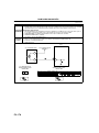
ON-BOARD DIAGNOSTIC
DTC No.
P0564
P0602
P0606
P0610
P0627
P0628
P0629
P0661
P0662
P0664
P0665
P0704
P0850
P1190
P1211
P1391
P1392
P2009
P2010
P2135
P2136
P2141
P2142
P2144
P2145
P2146
P2149
P2227
P2228
P2229
Condition
Cruise control signal malfunction
PCM programming error
PCM malfunction
Control module vehicle options error
Suction control valve circuit open
Suction control valve circuit low input
Suction control valve circuit high input
Intake shutter solenoid valve (half) circuit low input
Intake shutter solenoid valve (half) circuit high input
Intake shutter solenoid valve (full) circuit voltage low input
Intake shutter solenoid valve (full) circuit voltage high input
Clutch switch circuit malfunction
Neutral switch circuit malfunction
Calibration resistor circuit malfunction
Fuel pressure higher or lower than desired pressure
Glow plug circuit low input
Glow plug circuit high input
Variable swirl control (VSC) solenoid valve circuit high input
Variable swirl control (VSC) solenoid valve circuit low input
Accelerator pedal position (APP) sensor No.1/No.2 voltage correlation
Accelerator pedal position (APP) sensor No.1/idle switch correlation
EGR solenoid valve (vent) circuit low input
EGR solenoid valve (vent) circuit high input
EGR solenoid valve circuit low input
EGR solenoid valve circuit high input
Fuel injector No.1/No.4 circuit malfunction
Fuel injector No.2/No.3 circuit malfunction
BARO sensor range/performance problem
BARO sensor circuit low input
BARO sensor circuit high input
MIL
DC
OFF
ON
ON
ON
ON
ON
ON
ON
ON
ON
ON
ON
ON
ON
ON
OFF
OFF
ON
ON
ON
ON
ON
ON
ON
ON
ON
ON
ON
ON
ON
2
1
1
1
1
1
1
2
2
2
2
2
2
2
2
2
2
2
2
1
1
2
2
2
2
1
1
2
1
1
Memory
function
×
×
×
×
×
×
×
×
×
×
×
×
×
×
×
×
×
×
×
×
×
×
×
×
×
×
×
×
×
×
Sending Continuous Monitoring System Test Results
• These appear when a problem is detected in a monitored system.
1-drive cycle type
• If any problems are detected in the first drive cycle, pending codes will be stored in the PCM memory, as well
as DTCs.
• After pending codes are stored, if the PCM determines that the system is normal in any future drive cycle, the
PCM deletes the pending codes.
2-drive cycle type
• The code for a failed system is stored in the PCM memory in the first drive cycle. If the problem is not found in
the second drive cycle, the PCM determines that the system returned to normal or the problem was mistakenly
detected, and deletes the pending code. If the problem is found in the second drive cycle too, the PCM
determines that the system has failed, and stores the pending codes, and the DTCs.
• After pending codes are stored, if the PCM determines that the system is normal in any future drive cycle, the
PCM deletes the pending codes.
End Of Sie
DTC DETECTION LOGIC AND CONDITIONS
B6E407000102103
P0016 Crankshaft position-camshaft position correlation malfunction
• The PCM monitors the input signals from the CKP sensor and CMP sensor while engine is running. If the input
signals from the CKP sensor and the CMP sensor do not correspond, the PCM determines that there is a
correlation malfunction between crankshaft and camshaft position.
P0045 Variable boost control (VBC) solenoid valve control circuit low input
• The PCM monitors the output signal when the PCM controls the variable boost control solenoid valve between
30 and 70%. If the current of the variable boost control solenoid valve is less than 0.8 A during variable boost
control solenoid valve control, the PCM determines that there is a malfunction in the variable boost control
solenoid valve control circuit.
F2–21
F2
ON-BOARD DIAGNOSTIC
P0088 Fuel pressure system too high
• The PCM monitors the fuel pressure in the common rail from the fuel pressure sensor while the engine running.
If the fuel pressure is more than 188 MPa {1,917 kgf/cm2, 27,267 psi}, the PCM determines that the fuel
pressure is too high.
P0093 Fuel system leak detection
• The PCM monitors the fuel pressure in the common rail from the fuel pressure sensor while the engine running.
If the fuel pressure is lower after the fuel injection than the preprogrammed criteria, the PCM determines fuel
system leakage.
P0096 Intake air temperature (IAT) sensor No.2 range/performance problem
• The PCM monitors the input signal from intake air temperature sensor No.2. If the difference between the
maximum and minimum value of the intake air temperature sensor No.2 is less than 1 ° C {1.8 ° F}, the PCM
determines that there is a malfunction in intake air temperature sensor No.2.
P0097 Intake air temperature (IAT) sensor No.2 circuit low input
• The PCM monitors the input signal from intake air temperature sensor No.2. If the voltage from intake air
temperature sensor No.2 is less than 0.14 V, the PCM determines that there is a malfunction in the intake air
temperature sensor No.2 circuit.
P0098 Intake air temperature (IAT) sensor No.2 circuit high input
• The PCM monitors the input signal from intake air temperature sensor No.2. If the voltage from intake air
temperature sensor No.2 is more than 4.92 V, the PCM determines that there is a malfunction in the intake air
temperature sensor No.2 circuit.
P0101 Mass air flow (MAF) sensor range/performance problem
• The PCM monitors the input signal from the mass air flow sensor when the engine speed is between 600 rpm
and 2,100 rpm. If the voltage characteristic of the air flow sensor signal is out of the threshold, the PCM
determines that there is a malfunction in the mass air flow sensor.
P0102 Mass air flow (MAF) sensor circuit low input
• The PCM monitors the input signal from the air flow sensor. If the voltage from the air flow sensor is less than
0.15 V, the PCM determines that there is a malfunction in the air flow sensor circuit.
P0103 Mass air flow (MAF) sensor circuit high input
• The PCM monitors the input signal from the air flow sensor. If the voltage from the air flow sensor is more than
4.9 V, the PCM determines that there is a malfunction in the intake air temperature sensor No. 2 circuit.
P0106 Boost sensor range/performance problem
• The PCM monitors the vacuum inside the intake manifold. If the difference of the vacuum inside the intake
manifold during middle engine speed and low engine speed is less than the threshold, the PCM determines
that there is a malfunction in the manifold absolute pressure sensor characteristic.
P0107 Boost sensor circuit low input
• The PCM monitors the input signal from the manifold absolute pressure. If the voltage from the manifold
absolute pressure sensor is less than 0.4 V, the PCM determines that there is a malfunction in the manifold
absolute pressure sensor circuit.
P0108 Boost sensor circuit high input
• The PCM monitors the input signal from the manifold absolute pressure sensor. If the voltage from the manifold
absolute pressure sensor is more than 4.8 V, the PCM determines that there is a malfunction in the manifold
absolute pressure sensor circuit.
P0111 Intake air temperature (IAT) sensor No.1 range/performance problem
• The PCM monitors the input signal from intake air temperature sensor No.1. If the difference between the
maximum and minimum value of the intake air temperature sensor No.1 is less than 1 ° C {1.8 ° F}, the PCM
determines that there is a malfunction in intake air temperature sensor No.1.
P0112 Intake air temperature (IAT) sensor No.1 circuit low input
• The PCM monitors the input signal from intake air temperature sensor No.1. If the voltage from intake air
temperature sensor No.1 is less than 0.14 V, the PCM determines that there is a malfunction in the intake air
temperature sensor No.1 circuit.
P0113 Intake air temperature (IAT) sensor No.1 circuit high input
• The PCM monitors the input signal from intake air temperature sensor No.1. If the voltage from intake air
temperature sensor No.1 is more than 4.92 V, the PCM determines that there is a malfunction in the intake air
temperature sensor No.1 circuit.
P0116 Engine coolant temperature (ECT) sensor range/performance problem
• The PCM monitors the input signal from the engine coolant temperature sensor. If the difference between the
maximum and minimum value of the engine coolant temperature is less than 3 °C {5.4 ° F}, the PCM
determines that there is a malfunction in the engine coolant temperature sensor characteristic.
P0117 Engine coolant temperature (ECT) sensor circuit low input
• The PCM monitors the input signal from the engine coolant temperature sensor. If the voltage from the engine
coolant temperature sensor is less than 0.14 V, the PCM determines that there is a malfunction in the engine
coolant temperature sensor circuit.
P0118 Engine coolant temperature (ECT) sensor circuit high input
• The PCM monitors the input signal from the engine coolant temperature sensor. If the voltage from the engine
coolant temperature sensor is more than 4.92 V, the PCM determines that there is a malfunction in the engine
F2–22
ON-BOARD DIAGNOSTIC
coolant temperature sensor circuit.
P0122 Accelerator pedal position (APP) sensor No.1 circuit low input
• The PCM monitors the input signal from accelerator pedal position sensor No.1. If the voltage from accelerator
pedal position sensor No.1 is less than 0.3 V, the PCM determines that there is a malfunction in the
accelerator pedal position sensor No.1 circuit.
P0123 Accelerator pedal position (APP) sensor No.1 circuit high input
• The PCM monitors the input signal from accelerator pedal position sensor No.1. If the voltage from accelerator
pedal position sensor No.1 is more than 4.7 V, the PCM determines that there is a malfunction in the
accelerator pedal position sensor No.1 circuit.
P0182 Fuel temperature sensor circuit low input
• The PCM monitors the input signal from the fuel temperature sensor. If the voltage from the fuel temperature
sensor is less than 0.14 V, the PCM determines that there is a malfunction in the fuel temperature sensor
circuit.
P0183 Fuel temperature sensor circuit high input
• The PCM monitors the input signal from the fuel temperature sensor. If the voltage from the fuel temperature
sensor is more than 4.92 V, the PCM determines that there is a malfunction in the fuel temperature sensor
circuit.
P0191 Fuel pressure sensor range/performance problem
• The PCM monitors the fuel pressure in the common rail and input signal from the fuel pressure sensor while
the engine is running. If any one of the following conditions is met, the PCM determines that there is
malfunction in the fuel pressure sensor range/performance problem.
— The PCM calculates the difference between the actual fuel pressure and the target fuel pressure. If the
pressure difference more than 2 MPa {20 kgf/cm2, 290 psi}, the PCM determines that there is a
malfunction in fuel pressure sensor range/performance problem.
— The PCM monitors the input signal from fuel pressure sensor. If the difference between the maximum and
minimum value of the fuel pressure sensor is less than 0.015 V, the PCM determines that there is a
malfunction in fuel pressure sensor range/performance problem.
P0192 Fuel pressure sensor circuit low input
• PCM monitors input voltage from fuel pressure sensor while engine is running. If input voltage from fuel
pressure sensor is less than 0.4 V, PCM determines fuel pressure sensor circuit low input.
P0193 Fuel pressure sensor circuit high input
• PCM monitors input voltage from fuel pressure sensor while engine is running. If input voltage from fuel
pressure sensor is more than 4.86 V, PCM determines fuel pressure sensor circuit high input.
P0200 Fuel injector operation identified
• The PCM monitors each cylinder injection confirmation signal from the IDM while the engine is running. If the
PCM does not receive the injection confirmation signal for unspecified cylinder normally, the PCM determines
that the unspecified cylinder fuel injector operation is not verified.
P0201 Fuel injector No.1 operation identified
• The PCM monitors each cylinder injection confirmation signal from the IDM while the engine is running. If the
PCM does not receive the injection confirmation signal for No.1 cylinder normally, PCM determines that the fuel
injector No.1 operation is not verified.
P0202 Fuel injector No.2 operation identified
• The PCM monitors each cylinder injection confirmation signal from the IDM while the engine is running. If the
PCM does not receive the injection confirmation signal for No.2 cylinder normally, the PCM determines that the
fuel injector No.2 operation is not verified.
P0203 Fuel injector No.3 operation identified
• The PCM monitors each cylinder’s injection confirmation signal from the IDM while the engine is running. If the
PCM does not receive the injection confirmation signal for No.3 cylinder normally, the PCM determines that the
fuel injector No.3 operation is not verified.
P0204 Fuel injector No.4 operation identified
• The PCM monitors each cylinder injection confirmation signal from the IDM while the engine is running. If the
PCM does not receive the injection confirmation signal for No.4 cylinder normally, the PCM determines that the
fuel injector No.4 operation is not verified.
P0222 Accelerator pedal position (APP) sensor No.2 circuit low input
• The PCM monitors the input signal from accelerator pedal position sensor No.2. If the voltage from accelerator
pedal position sensor No.2 is less than 0.3 V, the PCM determines that there is a malfunction in the
accelerator pedal position sensor No.2 circuit.
P0223 Accelerator pedal position (APP) sensor No.2 circuit high input
• The PCM monitors the input signal from accelerator pedal position sensor No.2. If the voltage from accelerator
pedal position sensor No.2 is more than 4.7 V, the PCM determines that there is a malfunction in the
accelerator pedal position sensor No.2 circuit.
P0225 Idle switch circuit malfunction
• The PCM monitors the input signals from the accelerator pedal position sensor and the idle switch. If the idle
switch is off even if the voltage from the accelerator pedal position sensor No.2 is less than 0.75 V, the PCM
determines that there is a malfunction in the idle switch circuit.
F2–23
F2
ON-BOARD DIAGNOSTIC
P0301, P0302, P0303, P0304 Cylinder No.1/No.2/No.3/No.4 misfire detection
• The PCM monitors the CKP sensor input signal interval time. The PCM calculates the deviation of the interval
time for each cylinder. If the deviation of interval time exceeds the preprogrammed criteria, the PCM detects a
misfire in the corresponding cylinder. While the engine is running, the PCM counts the number of misfires and
calculates misfire ratio for each crankshaft revolution. If the ratio exceeds the preprogrammed criteria, the PCM
determines that a misfire, which can affect emission performance, has occurred.
P0336 CKP sensor range/performance problem
• The PCM monitors input signal from the CKP sensor while the engine is running. If the input signal from the
CKP sensor does not correspond with the proper pulse number, the PCM determines CKP sensor performance
problem.
P0337 CKP sensor circuit low input
• The PCM monitors the input signal from the CKP sensor and the CMP sensor while the engine is running. If the
input signal from the CKP sensor is not input while the PCM detects 28 pulses from the CMP sensor, the PCM
determines that there is a malfunction in the CKP sensor circuit.
P0341 CMP sensor range/performance problem
• The PCM monitors the input signal from the CMP sensor while the engine is running. If the input signal from the
CMP sensor does not correspond with the proper pulse number, the PCM determines CMP sensor
performance problem.
P0342 CMP sensor circuit low input
• The PCM monitors the input signal from the CMP sensor and the CKP sensor while the engine is running. If the
input signal from the CMP sensor is not input while the PCM detects 255 pulses from the CKP sensor, the
PCM determines that there is a malfunction in the CMP sensor circuit.
P0401 EGR flow insufficient detected
• The PCM monitors the difference between the target air amount and intake air amount while the EGR system is
operating. If the difference between the target air amount and the intake air amount is less than the threshold,
the PCM determines that there is a malfunction in the EGR system.
P0402 EGR flow excessive detected
• The PCM monitors the difference between the target air amount and intake air amount while the EGR system is
operating. If the difference between the target air amount and the intake air amount is more than the threshold,
the PCM determines that there is a malfunction in the EGR system.
P0404 EGR valve stuck
• The PCM monitors the input signal from the EGR valve position sensor while the EGR system is operating. If
the output voltage difference is less than threshold when the EGR flow amount changes, the PCM determines
that there is a malfunction in the EGR valve.
P0406 EGR valve position sensor circuit high input
• The PCM monitors the input signal from the EGR valve position sensor. If the voltage from the EGR valve
position sensor is more than 4.75 V, the PCM determines that there is a malfunction in the EGR valve position
sensor circuit.
P0489 EGR solenoid valve (vacuum) control circuit low input
• The PCM monitors the output signal to the EGR solenoid valve (vacuum). If the EGR solenoid valve (vacuum)
voltage is low even if the EGR solenoid valve (vacuum) is off, the PCM determines that there is a malfunction in
the intake shutter solenoid valve control circuit.
P0490 EGR solenoid valve (vacuum) control circuit high input
• The PCM monitors the output signal to the EGR solenoid valve (vacuum). If the EGR solenoid valve (vacuum)
voltage is high even if the EGR solenoid valve (vacuum) is on, the PCM determines that there is a malfunction
in the EGR solenoid valve (vacuum) control circuit.
P0500 Vehicle speed signal problem
• The PCM monitors the CAN input signal from the DSC HU/CM. If the input signal is not correct, the PCM
determines that there is a CAN input signal.
P0504 Brake switch signal correlation malfunction
• The PCM monitors the input signal from brake switch 1 and brake switch 2 while the engine is running. The
PCM determines the brake switch signal correlation malfunction if the input signal from brake switch 1 brake
switch 2 is as follows:
— Brake switch 1 is on and brake switch 2 is off.
— Brake switch 1 is off and brake switch 2 is on.
P0512 Engine switch circuit high input
• The PCM monitors the engine speed and the starter signal. If the engine speed is more than 700 rpm and the
starter switch ON signal is input, the PCM determines that there is a malfunction in the starter switch circuit.
P0562 Battery voltage low input
• The PCM monitors the battery voltage. If the battery voltage is less than 8 V, the PCM determines that there is
a malfunction in the battery and the battery signal system.
P0563 Battery voltage high input
• The PCM monitors the battery voltage. If the battery voltage is more than 16 V, the PCM determines that there
is a malfunction in the battery charging system.
F2–24
ON-BOARD DIAGNOSTIC
P0564 Cruise control signal malfunction
• The PCM monitors the input voltage from the cruise control switch while the engine is running. PCM
determines cruise control signal malfunction if the input voltage from the cruise control switch is as follows for
120 s:
— Below 0.1 V.
— 1.4—1.9 V.
— 3.7—3.9 V.
— 4.5—4.6 V.
P0602 PCM programming error
• No configuration data in PCM
P0606 PCM malfunction
• PCM does not read DTC from output devices.
P0610 Control module vehicle options error
• PCM data configuration error
P0627 Suction control valve circuit open
• The PCM monitors the suction control valve operation circuit signal frequency at PCM terminal 94. If the
difference between the suction control valve operation frequency at PCM terminal 93 and the monitored
suction control valve operation circuit signal frequency at PCM terminal 94 exceeds the threshold, the PCM
determines that suction control valve open circuit.
P0628 Suction control valve circuit low input
• The PCM monitors the suction control valve circuit current while the engine is running. If the PCM detects the
circuit current is less than 1 A when the suction control valve is on, the PCM determines that there is a
malfunction in the suction control valve circuit.
P0629 Suction control valve circuit high input
• The PCM monitors the suction control valve circuit current while the engine is running. If the PCM detects
circuit current more than 1 A when the suction control valve is off, the PCM determines that there is am
malfunction in the suction control valve circuit.
P0661 Intake shutter solenoid valve (half) circuit low input
• The PCM monitors the output signal to the intake shutter solenoid valve when the intake shutter solenoid valve
is off. If the intake shutter solenoid valve voltage is less than 7.8 V when the intake shutter solenoid valve off,
the PCM determines that there is a malfunction in the intake shutter solenoid valve control circuit.
P0662 Intake shutter solenoid valve (half) circuit high input
• The PCM monitors the output signal to the intake shutter solenoid valve when the intake shutter solenoid valve
is on. If the intake shutter solenoid valve voltage is more than 7.8 V when the intake shutter solenoid valve on,
the PCM determines that there is a malfunction in the intake shutter solenoid valve control circuit.
P0664 Intake shutter solenoid valve (full) circuit voltage low input
• The PCM monitors the output signal to the intake shutter solenoid valve. If the intake shutter solenoid valve
voltage is less than 7.8 V when the intake shutter solenoid valve is on, the PCM determines that there is a
malfunction in the intake shutter solenoid valve control system.
P0665 intake shutter solenoid valve (full) circuit voltage high input
• The PCM monitors the output signal to the intake shutter solenoid valve when intake shutter solenoid valve is
on. If the intake shutter solenoid valve voltage is more than 7.8 V when the intake shutter solenoid valve is on,
the PCM determines that there is a malfunction in the intake shutter solenoid valve control circuit.
P0704 Clutch switch circuit malfunction
• The PCM monitors input voltage from the clutch pedal position switch while the engine running. If the input
voltage from the clutch pedal position switch does not change when the vehicle stops after accelerating to
more than 30 km/h {18.6 mph} and decelerating to 0 km/h {0 mph}, the PCM determines that clutch pedal
position switch circuit has a malfunction.
P0850 Neutral switch circuit malfunction
• The PCM monitors the input signal from the neutral switch when shifting. If the neutral switch signal is not input
even once even when vehicle speed is more than 10 km/h {6.2 mph} the shift lever is operated more than
five times, the PCM determines that there is a malfunction in the neutral switch circuit.
P1190 Calibration resistor circuit malfunction
• The PCM monitors the input voltage from the calibration resistor. If the PCM detects that the input voltage for
any cylinder is more than 4.8 V or less than 0.2 V, the PCM determines calibration resistor malfunction.
P1211 Fuel pressure higher or lower than desired pressure
• The PCM monitors the fuel pressure and calculates the fuel supply volume to the common rail using the fuel
pressure sensor input signal while the engine is running. If the fuel pressure or fuel supply volume to the
common rail is as follows, the PCM determines that the fuel pressure is higher or lower than the desired
pressure.
— Supply pump actual pressure is higher than threshold.
— Difference between two consecutive fuel supply to common rail volume from supply pump is more than one
fuel injection volume by fuel injector.
P1391 Glow plug circuit low input
• The PCM monitors the output signal to the glow relay when the glow relay is on. If the glow relay voltage is 1.0
F2–25
F2
ON-BOARD DIAGNOSTIC
V or less when the glow relay is operating, The PCM determines that there is a malfunction in the glow relay
circuit.
P1392 Glow plug circuit high input
• The PCM monitors the output signal to the glow relay when the glow relay is off. If the glow relay voltage is 4.0
V or more when the glow relay is off, The PCM determines that there is a malfunction in the glow relay circuit.
P2009 Variable swirl control (VSC) solenoid valve circuit high input
• The PCM monitors the output signal to the variable swirl control solenoid valve. If the voltage of the variable
swirl control solenoid valve is high even if the variable swirl control solenoid valve is on, the PCM determines
that there is a malfunction in the variable swirl control solenoid valve control system.
P2010 Variable swirl control (VSC) solenoid valve circuit low input
• The PCM monitors the output signal to the variable swirl control solenoid valve. If the voltage of the variable
swirl control solenoid valve is low even if the variable swirl control solenoid valve is off, the PCM determines
that there is a malfunction in the variable swirl control solenoid valve control system.
P2135 Accelerator pedal position (APP) sensor No.1/No.2 voltage correlation
• The PCM monitors the input signals from accelerator pedal position sensor No.1 and accelerator pedal position
sensor No.2. If the difference between accelerator pedal position sensor No.1 and accelerator pedal position
sensor No.2 is more than 0.9 V, the PCM determines that there is a malfunction in the accelerator pedal
position sensor characteristic.
P2136 Accelerator pedal position (APP) sensor No.1/idle switch correlation
• The PCM monitors the input signal from accelerator pedal position sensor No.1. If the voltage from accelerator
pedal position sensor No.1 is more than 1.25 V during idle, the PCM determines that there is a malfunction in
the accelerator pedal position sensor No.1 characteristic.
P2141 EGR solenoid valve (vent) circuit low input
• The PCM monitors the output signal to the EGR solenoid valve (vent). If the EGR solenoid valve (vent) voltage
is low even if the EGR solenoid valve (vent) is off, the PCM determines that there is a malfunction in the intake
shutter solenoid valve control system.
P2142 EGR solenoid valve (vent) circuit high input
• The PCM monitors the output signal to the EGR solenoid valve (vent). If the EGR solenoid valve (vent) voltage
is high even if the EGR solenoid valve (vent) is on, the PCM determines that there is a malfunction in the EGR
solenoid valve (vent) control system.
P2144 EGR control solenoid valve circuit low input
• The PCM monitors the output signal to the EGR control solenoid valve. If the EGR control solenoid valve
voltage is low even if the EGR control solenoid valve is off, the PCM determines that there is a malfunction in
the EGR control solenoid valve control circuit.
P2145 EGR control solenoid valve circuit high input
• The PCM monitors the output signal to the EGR control solenoid valve. If the EGR control solenoid valve
voltage is high even if the EGR control solenoid valve is on, the PCM determines that there is a malfunction in
the EGR control solenoid valve control circuit.
P2146 Fuel injector No.1/No.4 circuit malfunction
• The PCM monitors each cylinder injection confirmation signal from the IDM while the engine is running. If the
PCM does not receive the injection confirmation signal for No.1 and No.4 cylinder normally, the PCM
determines that the fuel injector No.1 and No.4 operation is not verified.
P2149 Fuel injector No.2/No.3 circuit malfunction
• The PCM monitors each cylinder’s injection confirmation signal from the IDM while the engine is running. If the
PCM does not receive the injection confirmation signal for No.2 and No.3 cylinder normally, the PCM
determines that the fuel injector No.2 and No.3 operation is not verified.
P2227 BARO sensor range/performance problem
• The PCM monitors the input signal from the barometric pressure sensor. If the difference between the
barometric pressure input from the barometric pressure sensor and the manifold absolute pressure is more
than 75 mmHg, the PCM determines that there is a malfunction in the barometric pressure sensor.
P2228 BARO sensor circuit low input
• The PCM monitors the input signal from the barometric pressure sensor. If the voltage from the barometric
pressure sensor is less than 0.4 V, the PCM determines that there is a malfunction in the barometric pressure
sensor signal system.
P2229 BARO sensor circuit high input
• The PCM monitors the input signal from the barometric pressure sensor. If the voltage from the barometric
pressure sensor is more than 4.7 V, the PCM determines that there is a malfunction in the barometric pressure
sensor signal system.
End Of Sie
PID/DATA MONITOR AND RECORD
• The PID/DATA monitor items are shown below.
F2–26
B6E407000102104
ON-BOARD DIAGNOSTIC
PID/DATA monitor item table
Monitor item
AC_REQ
ACCS
ACR
APS1
APS2
ARPMDES
BARO
BOO
BOOST_DSD
CPP
CPP/PNP
CR_1
CR_2
CR_3
CR_4
CRUISESW
DEC_CMP
DSC_ACT
DTCCNT
ECT
EGRA
EGRV
EGRV2
EGRVP
FAN1
FAN3
FFH_STAT
FIP_FL
FIP_FL_DSD
FIP_LRN
FIP_MODE
FIP_SCV
FLT
FLTV
FRP
FRP_A
GLWPG V
GPC
IASV
IASV2
IAT
IAT2
ICP
IMRC
Unit/Condition
On/Off
On/Off
On/Off
V
V
RPM
kPa psi Bar
V
On/Off
kPa psi Bar
On/Off
Neutral/Drive
V
V
V
V
On/Off
Definition
A/C request signal.
Air conditioning compressor cycling switch
A/C relay
Accelerator position sensor No.1 - voltage
Accelerator position sensor No.2 - voltage
Target engine speed
mm3 par stroke
Enabled/
Disabled
—
°C
°F
V
%
%
On/Off
V
On/Off
On/Off
Active/Inactive
Current
%
Desired fuel for torque down control
mm3 par stroke
Current
Normal/Fixed_1/
Fixed_2/
Disabled
Current
V
°C
°F
V
V
kPa psi Bar
kPa psi Bar
V
On/off
On/Off
On/Off
V
°C
°F
V
°C
°F
kPa psi Bar
On/Off
Barometric pressure
Brake switch
Desired boost pressure
Clutch switch
Neutral switch
Calibration resistor voltage 1
Calibration resistor voltage 2
Calibration resistor voltage 3
Calibration resistor voltage 4
Cruise control switch
F2
DSC control enable/disable
DTC count
Engine coolant temperature
Exhaust gas recirculation solenoid valve (vent)
Exhaust gas recirculation solenoid valve (vacuum)
Exhaust gas recirculation control solenoid valve
Exhaust gas recirculation valve position sensor
Cooling fan relay No.2 (Main fan relay)
Cooling fan relay No.1 (Add fan relay)
FFH status
FIP flow control
FIP flow desired
FIP learning amount
FIP duty control status
FIP suction control valve
Fuel temperature
FLT signal voltage
Fuel rail pressure
FRP after fuel injection
Glow plugs
Glow plug control
intake shutter solenoid valve (full) control
intake shutter solenoid valve (full) control
Intake air temperature
Intake air temperature No.2
Injector control pressure
VSC solenoid valve control
F2–27
ON-BOARD DIAGNOSTIC
Monitor item
INGEAR
INJ_LRN_DIS
INJ_MODE
INJ_TIM
INJ1_CMP
INJ2_CMP
INJ3_CMP
INJ4_CMP
Unit/Condition
Definition
On/Off
Load/no load condition
km
mile
Distance from the last injector learning
Normal/
Disabled/
Fuel injection timing control status
Splitted/Fixed
°
Fuel injection timing
Injector 1 correction value
Injector 2 correction value
mm3 par stroke
Injector 3 correction value
Injector 4 correction value
mm3 par stroke
Idle/Off Idle
g/s
V
g
g
km
mile
On/Off
kPa psi Bar
V
On/Off
1_INJ/2_INJ/
3_INJ/4_INJ/
5_INJ/6_INJ/
Disabled
—
RPM
On/Off
Applied/Not
Applied
Active/Inactive
Active/Inactive
Active/Inactive
Active/Inactive
On/Off
ISC_CMP
IVS
MAF
MAF_C
MAF_C_DSD
MAF_LRN_DIS
MAINRLY
MAP
MIL
MULTI_INJ
NUMKEYS
RPM
SC_BOO
SC_CANCEL
SC_COAST
SC_MAIN
SC_RES
START_SW
Fuel correction for idle speed control
Idle switch
Mass air flow amount
MAF per cylinder
MAF per cylinder desired
Distance from the last MAF learning
PCM control relay
Manifold absolute pressure
Malfunction indicator lamp
Multiple fuel injection control status
Number of keys stored in module
Engine speed
Brake switch for cruise
Cruise cancel switch
Cruise coast switch
Cruise main switch
Cruise resume switch
Starter switch value
mm3 par stroke Fuel correction when torque down control
%
VBC solenoid valve control
TC_CMP
VBCV
mm3 par stroke Volume fuel desired
V
Battery positive voltage
km/h
mph Vehicle speed sensor.
VFDES
VPWR
VSS
End Of Sie
SIMULATION TEST
B6E407000102105
• The simulation items are shown below.
Simulation item table
Item
ACCS
EGRA
EGRV
EGRV2
FAN1
FAN3
GP_LMP
F2–28
×: Applicable
—: Not applicable
Applicable component
Unit/condition
Air conditioning compressor cycling switch
EGR solenoid valve (vent)
EGR solenoid valve (vacuum)
EGR control solenoid valve
Cooling fan relay No.2 (Main fan relay)
Cooling fan relay No.1 (Add fan relay)
Glow plug lamp
ON/OFF
Any Duty (%)
Any Duty (%)
ON/OFF
ON/OFF
ON/OFF
ON/OFF
Test condition
KOEO
KOER
×
×
×
×
×
×
×
×
×
×
×
×
×
×
PCM terminal
73
72
99
77
76
102
—
ON-BOARD DIAGNOSTIC
Item
FUEL_PRIME
GPC
IASV
IASV2
IMRC
VBCV
Applicable component
Fuel pump priming command
Glow plug relay
Intake shutter solenoid valve (half)
Intake shutter solenoid valve (full)
VSC solenoid valve
VBC solenoid valve
Unit/condition
ON/--ON/OFF
ON/OFF
ON/OFF
ON/OFF
Any Duty (%)
Test condition
KOEO
KOER
×
×
×
×
×
×
×
×
×
×
×
×
PCM terminal
—
68
74
100
101
67
End Of Sie
F2
F2–29
OUTLINE
OUTLINE
SUPPLEMENTAL SERVICE INFORMATION
B6E400218881106
• The following changes and/or additions have been made since publication of the Mazda6 Workshop Manual
(1749-1*-02G).
PCM
• PCM inspection has been modified.
EGR valve position sensor
• Inspection procedure has been added.
On-board diagnostic
• Inspection procedure has been modified.
Troubleshooting
• Inspection procedure has been modified.
End Of Sie
F2–30
CONTROL SYSTEM
CONTROL SYSTEM
PCM INSPECTION
B6E404018881105
Using WDS or Equivalent
Caution
• The PCM terminal voltage vary with change in measuring conditions and vehicle conditions.
Always carry out a total inspection of the input systems, output systems, and PCM to determine
the cause of trouble. Otherwise, diagnosis will be incorrect.
Note
• For replace the PCM, setup the WDS and perform the following.
— “PCM configuration”
— “Correction after Parts Installation”
F2
1. Connect the WDS or equivalent to the DLC-2. (See F2–38 ON-BOARD DIAGNOSTIC TEST.)
2. Turn the engine switch to ON.
3. Measure the PID value.
• If PID value is not within the specification, follow the instructions in ACTION column.
F2–31
CONTROL SYSTEM
PID Monitor Table
Monitor item
(Definition)
Unit/Condition
Condition/Specification (Reference)
AC_REQ
(A/C request signal)
On/Off
KOER
A/C switch ON: On
A/C switch OFF: Off
ACCS
(Air conditioning
compressor cycling
switch)
On/Off
KOER
A/C switch ON and fan
switch ON at idle: On
Other: Off
ACR
(A/C relay)
On/Off
KOER
A/C switch ON and fan
switch ON at idle: On
Other: Off
APS1
(Accelerator position
sensor No.1 - voltage)
V
KOEO/
KOER
APS2
(Accelerator position
sensor No.2 - voltage)
V
KOEO/
KOER
ARPMDES
(Target engine speed)
BARO
(Barometric pressure)
kPa
CPP
(Clutch switch)
CPP/PNP
(Neutral switch)
CR_1
(Calibration resistor
voltage 1)
CR_2
(Calibration resistor
voltage 2)
CR_3
(Calibration resistor
voltage 3)
CR_4
(Calibration resistor
voltage 4)
CRUISESW
(Cruise control switch)
DEC_CMP
(Fuel correction for
deceleration)
F2–32
psi
Bar
V
BOO
(Brake switch)
BOOST_DSD
(Desired boost
pressure)
KOER
(Idle)
RPM
KOEO/
KOER
On/Off
kPa
psi
KOEO/
KOER
Accelerator pedal
released: Approx. 0.6 V
Accelerator pedal fully
depressed: Approx. 3.6 V
Accelerator pedal
released: Approx. 0.6 V
Accelerator pedal fully
depressed: Approx. 3.6 V
No load: 725—825 rpm
E/L operating: 725—825
rpm
P/S operating: 725—825
rpm
A/C ON: 725—825 rpm
Indicate Barometric
pressure
BARO 101.3 kPa: Approx.
4V
Brake pedal released: Off
Brake pedal depressed:
On
Bar Desired boost pressure is displayed
On/Off
KOEO/
KOER
Neutral/Drive
KOEO/
KOER
Inspection item
Inspect following PIDs:
START_SW, CPP, CPP/PNP,
IVS, AC_REQ, APS1, APS2,
ECT, RPM.
Inspect following PIDs:
START_SW, CPP, CPP/PNP,
IVS, AC_REQ, APS1, APS2,
ECT, RPM.
Inspect following PIDs:
START_SW, CPP, CPP/PNP,
IVS, AC_REQ, APS1, APS2,
ECT, RPM.
Inspect A/C relay
PCM
terminal
84
73
73
Inspect Accelerator position
sensor No.1
10
Inspect Accelerator position
sensor No.2
88
Inspect following PIDs:
START_SW, CPP, CPP/PNP,
IVS, AC_REQ, APS1, APS2,
IAT2, ECT, BOOST_DSD, FRP,
FRP_A, RPM, VSS.
—
Inspect BARO sensor.
—
Inspect brake switch.
7
Perform applicable DTC
troubleshooting.
—
Clutch pedal released: Off
Clutch pedal depressed:
Inspect clutch switch.
On
Neutral position: Neutral
Inspect neutral switch.
Others: Drive
33
56
37
62
V
KOEO/
KOER
Calibration resistor
voltage is displayed
Inspect neutral calibration
resistor.
89
11
On/Off
KOEO/
KOER
Cruise control switch OFF:
Off
Inspect cruise control switch
Cruise control switch ON:
On
Fuel correction for deceleration is
mm3 per stroke displayed.
—
64
—
CONTROL SYSTEM
Monitor item
(Definition)
DSC_ACT
(DSC control enable/
disable)
DTCCNT
(DTC count)
Unit/Condition
Enabled/
Disabled
—
°C
ECT
(Engine coolant
temperature)
EGRA
(Exhaust gas
recirculation solenoid
valve (vent))
EGRV
(Exhaust gas
recirculation solenoid
valve (vacuum))
EGRV2
(Exhaust gas
recirculation control
solenoid valve)
EGRVP
(Exhaust gas
recirculation valve
position sensor)
FAN1
(Cooling fan relay
No.2 (Main fan relay))
FAN3
(Cooling fan relay
No.1 (Add fan relay))
FFH_STAT
(FFH status)
°F
V
%
%
On/Off
V
Condition/Specification (Reference)
KOEO
Disable
KOER
Idle: Enabled
Number of DTCs stored in the PCM is
displayed.
Engine coolant
temperature is displayed
KOEO/
ECT 25 °C {77 °F}:
KOER
Approx. 2.85 V
ECT 80 °C {176 °F}:
Approx. 0.89 V
KOEO
Approx. 0 %
KOER
Idle: Approx. 100 %
KOEO
Approx. 0 %
KOER
Idle: Approx. 75—79 %
KOEO
Off
KOER
Idle: On
On/Off
KOER
(Idle)
On/Off
KOER
(Idle)
Active/Inactive
KOER
(Idle)
FIP_FL_DSD
(FIP flow desired)
%
PCM
terminal
—
—
Perform applicable DTC
troubleshooting.
—
Inspect ECT sensor.
87
Inspect following PIDs:
START_SW, CPP, CPP/PNP,
IVS, AC_REQ, MAF, APS1,
APS2, ECT, BARO,
BOOST_DSD, FRP, FRP_A,
RPM, VSS.
Inspect EGR solenoid valve
(vent).
Inspect following PIDs:
START_SW, CPP, CPP/PNP,
IVS, AC_REQ, MAF, APS1,
APS2, ECT, BARO,
BOOST_DSD, FRP, FRP_A,
RPM, VSS.
Inspect EGR solenoid valve
(vacuum).
Inspect following PIDs:
START_SW, CPP, CPP/PNP,
IVS, AC_REQ, MAF, APS1,
APS2, ECT, BARO,
BOOST_DSD, FRP, FRP_A,
RPM, VSS.
Inspect EGR solenoid valve.
See F2–37 EGR VALVE POSITION SENSOR INSPECTION.
Current
FIP_FL
(FIP flow control)
Inspection item
ECT below 100 °C {212
°F}: Off
Others: On
ECT below 100 °C {212
°F}: Off
A/C operating, refrigerant
pressure switch (middle)
is ON, and ECT below 108
°C {226 °F}: Off
Other: On
Inactive
Approx. 1.8 A
KOER
(Idle)
Approx. 44.4 %
KOEO
Approx. 0 mm3/stroke
mm3 per stroke KOER
(Idle)
Approx. 55 mm3/stroke
F2
72
99
77
32
Inspect following PIDs: VPWR,
AC_REQ, APS1, APS2, ECT
Inspect cooling fan relay.
76
Inspect following PIDs: VPWR,
AC_REQ, APS1, APS2, ECT
Inspect cooling fan relay.
102
—
—
Inspect following PIDs:
START_SW, CPP, CPP/PNP,
IVS, AC_REQ, APS1, APS2,
IAT2, ECT, BOOST_DSD, FRP,
FRP_A, RPM, VSS.
Inspect IDM.
Inspect following PIDs:
START_SW, CPP, CPP/PNP,
IVS, AC_REQ, APS1, APS2,
IAT2, ECT, BOOST_DSD, FRP,
FRP_A, RPM, VSS.
30
—
F2–33
CONTROL SYSTEM
Monitor item
(Definition)
Unit/Condition
FIP_LRN
(FIP learning amount)
Current
FIP_MODE
(FIP duty control
status)
Normal/
Fixed_1/
Fixed_2/
Disabled
Current
FIP_SCV
(Suction control valve)
FLT
(Fuel temperature)
FLTV
(FLT signal voltage)
V
°C
°F
V
V
Condition/Specification (Reference)
KOEO
Approx. 64 mA
KOER
(Idle)
Approx. 77 mA
KOEO
Disabled
KOER
Normal
KOEO
KOER
KOEO
Approx. 24 mA
1.5—2.2 A
Approx. 0.02 V
KOER
1.6—2.2 V
KOEO/
KOER
KOEO/
KOER
KOEO
Fuel temperature is
displayed.
FLT 23 °C {73 °F}:
Approx. 2.23 V
Approx. 1 V
Idle: Approx. 1.54 V
2,000 rpm: Approx. 1.7 V
0 kPa {0 psi, 0 Bar}
Idle: Approx. 34 MPa
{4,931 psi, 340 Bar}
2,000 rpm: Approx. 43
MPa {6,237 psi, 430 Bar}
0 kPa {0 psi, 0 Bar}
Idle: Approx. 34 MPa
{4,931 psi, 340 Bar}
2,000 rpm: Aprrox.43 MPa
{6,237 psi, 430 Bar}
Approx. 0 V
Cranking: Approx. 10 V
Idle: Approx. 0 V
Off
Cranking: On
Idle: Off
Off
Idle: On
KOER
FRP
(Fuel pressure sensor)
KOEO
kPa
psi
Bar
KOER
KOEO
FRP_A
(FRP after fuel
injection)
kPa
psi
KOER
KOEO
GLWPG V
(Glow plugs)
GPC
(Glow plug control)
Bar
V
KOER
KOEO
On/Off
KOER
KOEO
IASV
(intake shutter
solenoid valve (half)
control)
IASV2
(intake shutter
solenoid valve (full)
control)
IAT
(Intake air
temperature)
IAT2
(Intake air temperature
No.2)
F2–34
On/Off
On/Off
V
°C
°F
V
°C
°F
KOER
1,100 rpm or more: On
KOEO
Off
KOER
Idle: Off
KOEO/
KOER
KOEO/
KOER
Inspection item
Inspect following PIDs:
START_SW, CPP, CPP/PNP,
IVS, AC_REQ, APS1, APS2,
IAT2, ECT, BOOST_DSD, FRP,
FRP_A, RPM, VSS.
Inspect following PIDs:
START_SW, CPP, CPP/PNP,
IVS, AC_REQ, APS1, APS2,
IAT2, ECT, BOOST_DSD, FRP,
FRP_A, RPM, VSS.
Inspect following PIDs:
START_SW, CPP, CPP/PNP,
IVS, AC_REQ, APS1, APS2,
IAT2, ECT, BOOST_DSD, FRP,
FRP_A, RPM, VSS.
PCM
terminal
—
—
93, 94
Inspect fuel temperature sensor
35
Inspect fuel pressure sensor
61
Inspect following PIDs:
START_SW, ECT,
BOOST_DSD, VSS
86
Inspect following PIDs:
START_SW, CPP, CPP/PNP,
IVS, APS1, APS2, IAT2, MAF,
ECT, BOOST_DSD, RPM,
VSS.
Inspect intake shutter solenoid
valve (half).
Inspect following PIDs:
START_SW, CPP, CPP/PNP,
IVS, APS1, APS2, IAT2, MAF,
ECT, BOOST_DSD, RPM,
VSS.
Inspect intake shutter solenoid
valve (full).
30°C {86 °F}: Approx. 1.9
V
Inspect IAT sensor.No.1
Intake air temperature is
display
23 °C {73 °F}: Approx. 2.2
V
Inspect IAT sensor.No.2
Intake air temperature is
display
74
100
60
8
CONTROL SYSTEM
Monitor item
(Definition)
Unit/Condition
Condition/Specification (Reference)
KOEO
ICP
(Injector control
pressure)
IMRC
(VSC solenoid valve
control)
INGEAR
(Load/no load
condition)
INJ_LRN_DIS
(Distance from the last
injector learning)
INJ_MODE
(Fuel injection timing
control status)
kPa
psi
KOER
KOEO
On/Off
On/Off
km
mile
Normal/
Disabled/
Splitted/Fixed
INJ_TIM
(Fuel injection timing)
INJ1_CMP
(Injector 1 correction
value)
INJ2_CMP
(Injector 2 correction
value)
INJ3_CMP
(Injector 3 correction
value)
INJ4_CMP
(Injector 4 correction
value)
ISC_CMP
(Fuel correction for
idle speed control)
IVS
(Idle switch)
Bar
°
Inspect following PIDs:
START_SW, CPP, CPP/PNP,
IVS, AC_REQ, APS1, APS2,
IAT2, ECT, BOOST_DSD, FRP,
FRP_A, RPM, VSS.
—
Inspect following PIDs: CPP,
CPP/PNP, APS1, APS2, IVS,
MAF, ECT, RPM.
Inspect VSC solenoid valve.
101
KOER
Idle: On
1,900 rpm or more: Off
KOEO/
KOER
CPP or CPP/PNP is on:
On
Others: Off
Inspect following PIDs: CPP,
CPP/PNP.
—
KOEO/
KOER
Distance from the last
injector learning
Distance from the last injector
learning is display.
—
KOEO
Disabled
KOER
Idle: Normal
KOEO
Approx. 30°
KOER
Idle: Approx. 30°
2,000 rpm: Approx. 30°
Inspect following PIDs:
START_SW, CPP, CPP/PNP,
IVS, MAF, ECT, FRP, FRP_A,
RPM, VSS.
Inspect following PIDs:
START_SW, CPP, CPP/PNP,
IVS, MAF, ECT, FRP, FRP_A,
RPM, VSS.
KOEO/
mm3 per stroke KOER
F2
—
42, 43,
44, 45
Inspect following PIDs:
START_SW, CPP, CPP/PNP,
Injector correction value is
IVS, APS1, APS2, IAT2, ECT,
displayed
BOOST_DSD, FRP, FRP_A,
RPM, VSS.
45
43
44
KOEO/
mm3 per stroke KOER
Fuel correction for idle
speed control is displayed
KOEO/
KOER
KOEO
CTP: Idle
Others: Off Idle
0 g/s
Idle: Approx. 13 g/s
2,000 rpm: Approx. 21 g/s
Less than 1V
Idle: Approx. 2.1 V
2,000 rpm: Approx. 2.4 V
Approx. 78.44 mg
Idle: Approx. 590 mg
2,000 rpm: Approx. 400
mg
Approx. 1.01 mg
Idle: Approx. 358 mg
2,000 rpm: Approx. 320
mg
Idle/Off Idle
g/s
KOER
KOEO
V
KOER
KOEO
MAF_C
(MAF per cylinder)
g
KOER
KOEO
MAF_C_DSD
(MAF per cylinder
desired)
MAINRLY
(PCM control relay)
PCM
terminal
42
MAF
(Mass air flow amount)
MAF_LRN_DIS
(Distance from the last
MAF learning)
35 MPa {5,076 psi, 350
Bar}
Idle: Approx.35 MPa
{5,076 psi, 350 Bar}
2,000 rpm: Approx.45
MPa {6,526.7 psi, 450
Bar}
Off
Inspection item
g
km
KOER
mile
On/Off
—
—
Inspect Idle switch
31
Inspect MAF sensor.
9
Inspect MAF sensor.
—
Inspect MAF sensor.
—
KOEO/
KOER
Distance from the last
MAF learning is displayed
—
—
KOEO
KOER
On
Idle: On
—
69
F2–35
CONTROL SYSTEM
Monitor item
(Definition)
MAP
(Manifold absolute
pressure)
MIL
(Malfunction indicator
lamp)
MULTI_INJ
(Multiple fuel injection
control status)
NUMKEYS
(Number of keys
stored in module)
RPM
(Engine speed)
Unit/Condition
kPa
Condition/Specification (Reference)
psi
Bar KOER
V
KOEO
On/Off
1_INJ/2_INJ/
3_INJ/4_INJ/
5_INJ/6_INJ/
Disabled
—
RPM
KOEO
KOER
(Idle)
KOEO
KOER
Applied/Not
Applied
KOER
0 RPM
No load: 725—825 RPM
E/L operating: 725—825
RPM
P/S operating: 725—825
RPM
A/C ON: 725—825 RPM
Brake pedal released: Off
Brake pedal depressed:
On
Brake pedal released: Not
Applied
Brake pedal depressed:
Applied
Cruise cancel switch
released: Inactive
Cruise cancel switch
depressed: Active
Cruise coast switch
released: Inactive
Cruise coast switch
depressed: Active
Cruise control switch OFF:
Inactive
Cruise control switch ON:
Active
Cruise resume switch
released: Inactive
Cruise resume switch
depressed: Active
Off
Cranking: On
Idle: Off
KOER
KOEO/
KOER
Active/Inactive
KOEO/
KOER
SC_COAST
(Cruise coast switch)
Active/Inactive
KOEO/
KOER
SC_MAIN
(Cruise main switch)
Active/Inactive
KOEO/
KOER
SC_RES
(Cruise resume
switch)
Active/Inactive
KOEO/
KOER
TC_CMP
(Fuel correction for
traction control)
VBCV
(VBC solenoid valve
control)
F2–36
KOEO
On/Off
KOER
KOEO/
mm3 per stroke KOER
KOEO
%
Disabled
Idle: 4_INJ
As increase the engine
speed: 4_INJ→ 3_INJ→
2_INJ→ 1_INJ
Release the accelerator
pedal while the engine
speed is high: Disabled
Number of keys stored in
module
SC_CANCEL
(Cruise cancel switch)
START_SW
(Starter switch value)
Off
KOEO/
KOER
On/Off
SC_BOO
(Brake switch for
cruise)
Manifold absolute
pressure is displayed
Approx. 4.1 V (at sea
level)
On
KOER
Inspection item
PCM
terminal
Inspect MAP sensor.
36
Perform applicable DTC
troubleshooting.
—
Inspect following PIDs:
START_SW, CPP, CPP/PNP,
IVS, AC_REQ, APS1, APS2,
MAF, IAT2, ECT, FLT, RPM,
VSS.
—
—
—
Inspect CKP sensor.
3, 29
Inspect brake switch
34
Inspect cruise cancel switch
64
Inspect cruise cancel switch
64
Inspect cruise cancel switch
64
Inspect cruise cancel switch
64
Inspect cruise cancel switch
57
Inspect following PIDs:
START_SW, CPP, CPP/PNP,
Fuel correction for traction
IVS, AC_REQ, APS1, APS2,
control is display.
IAT2, ECT, BOOST_DSD, FRP,
FRP_A, RPM, VSS.
0%
Inspect following PIDs: CPP,
CPP/PNP, APS1, APS2, IVS,
Idle: Approx. 51 %
MAF, ECT, RPM.
2,000 rpm: Approx. 50 % Inspect VBC solenoid valve.
—
67
CONTROL SYSTEM
Monitor item
(Definition)
VFDES
(Volume fuel desired)
VPWR
(Battery positive
voltage)
VSS
(Vehicle speed)
Unit/Condition
Inspection item
PCM
terminal
Volume fuel desired is
displayed
Inspect following PIDs:
START_SW, CPP, CPP/PNP,
IVS, AC_REQ, APS1, APS2,
IAT2, ECT, BOOST_DSD, FRP,
FRP_A, RPM, VSS.
—
KOEO
Battery positive voltage is
displayed
Inspect PCM control relay.
Inspect battery.
KOER
Vehicle speed is displayed
Perform applicable DTC
troubleshooting.
Condition/Specification (Reference)
KOEO/
mm3 per stroke KOER
V
km/h
mph
27, 53,
79
—
End Of Sie
EGR VALVE POSITION SENSOR INSPECTION
B6E404018881106
Voltage Inspection
1. Disconnect the vacuum hose from the EGR valve position sensor and connect the vacuum pump to the EGR
valve.
2. Turn the engine switch to the ON position.
3. Verify that the voltage at terminal B changes while applying the vacuum to the EGR valve as show in the graph.
• If not as specified, replace the EGR valve.
Specification
(V)
.
0.54
Vacuum
0— –36.6 kPa {0— –274.5
mmHg, 0— –10.8 inHg} or
above
–73.3 {-549.8 mmHg, –21.7
inHg} or below
Voltage
4.09—4.59 V
4.09—4.59
Approx. 0.54 V
-36.6
{-274.5, -10.8}
-73.3 (kPa {mmHg, inHg})
{-549.8, -21.7}
BPE4040W001
Resistance Inspection
1. Disconnect the EGR valve position sensor connector.
2. Measure the resistance between terminal A and C.
• If not as specified, replace the EGR valve.
EGR valve position sensor resistance
Approx. 5 kilohms
C
B
A
B6E4040W003
End Of Sie
F2–37
F2
ON-BOARD DIAGNOSTIC
ON-BOARD DIAGNOSTIC
FOREWORD
B6E407018881101
• When the customer reports a vehicle malfunction, check the malfunction indicator light (MIL) indication and
diagnostic trouble code (DTC), then diagnose the malfunction according to following flowchart.
— If the DTC exists, diagnose the applicable DTC inspection. (See F2–40 DTC TABLE.)
— If the DTC does not exist and the MIL does not illuminate or flash, diagnose the applicable symptom
troubleshooting.
CUSTOMER ARRIVES
WARNING LIGHT*
ON/FLASHING
NO WARNING LIGHT*
WITH SYMPTOM
CHECK FOR
PRIORITIZED DTC
•CHECK DTC
•IGNITION ON TEST, IDLING TEST
DTC
WITHOUT DTC
DIAGNOSE BY DTC
(ON-BOARD DIAGNOSTIC)
•DTC TABLE
•DTC
TROUBLESHOOTING
FLOW
DIAGNOSE BY SYMPTOM
(SYMPTOM TROUBLESHOOTING)
1. DIAGNOSTIC INDEX
2. QUICK DIAGNOSIS CHART
3. SYMPTOM TROUBLESHOOTING
B6U0102W301
* : Malfunction Indicator Light (MIL), Generator Warning Light, Security Light
End Of Sie
OBD PENDING TROUBLE CODES
B6E407018881102
• These appear when a problem is detected in a monitored system. The MIL is illuminated when a problem is
detected in two consecutive drive cycles. The code for a failed system is stored in the PCM memory in the first
drive cycle. This code is called the pending code. If the problem is not found in the second drive cycle, the PCM
judges that the system returned to normal or the problem was mistakenly detected, and deletes the pending
code. If the problem is found in the second drive cycle too, the PCM judges that the system has failed, deletes
the pending code, illuminates the MIL and stores the DTC.
End Of Sie
OBD FREEZE FRAME DATA
B6E407018881103
• This is the technical data which indicates the engine’s condition at the time of the first malfunction. This data
will remain in the memory even if another emission-related DTC is stored, with the exception of Misfire or Fuel
System DTCs. Once freeze frame data for a Misfire or Fuel System DTC is stored, it will overwrite any previous
data and the freeze frame will not be overwritten again.
End Of Sie
OBD READ/CLEAR DIAGNOSTIC TEST RESULTS
B6E407018881104
• This retrieves all stored DTCs in the PCM and clears the DTC, Freeze Frame Data, On-Board Readiness Test
Results, Diagnostic Monitoring Test Results and Pending Trouble Codes.
End Of Sie
OBD PARAMETER IDENTIFICATION (PID) ACCESS
B6E407018881105
• The PID mode allows access to certain data values, analog and digital inputs and outputs, calculated values
and system status information. Since PID values for output devices are PCM internal data values, inspect each
device to identify which output devices are malfunctioning.
End Of Sie
ON-BOARD DIAGNOSTIC TEST
DTCs Retrieving Procedure
1. Perform the necessary vehicle preparation and visual inspection.
F2–38
B6E407018881106
ON-BOARD DIAGNOSTIC
2. Connect WDS or equivalent to the vehicle DLC-2
16-pin connector located on the left side of the
steering column.
3. Retrieve DTC using WDS or equivalent.
DLC-2
A6E40702001
Pending Trouble Code Access Procedure
1. Perform the necessary vehicle preparation and visual inspection.
2. Connect WDS or equivalent to the vehicle DLC-2
16-pin connector located on the left side of the
steering column.
3. Retrieve pending trouble code using WDS or
equivalent.
F2
DLC-2
A6E40702001
Freeze Frame PID Data Access Procedure
1. Perform the necessary vehicle preparation and visual inspection.
2. Connect WDS or equivalent to the vehicle DLC-2
16-pin connector located on the left side of the
steering column.
3. Retrieve FREEZE FRAME PID DATA using WDS
or equivalent.
DLC-2
A6E40702001
PID/DATA Monitor and Record Procedure
1. Perform the necessary vehicle preparation and visual inspection.
2. Connect WDS or equivalent to the vehicle DLC-2
16-pin connector located on the left side of the
steering column.
3. Access and monitor PIDs using WDS or
equivalent.
DLC-2
A6E40702001
End Of Sie
OBD DRIVE MODE
B6E407018881107
• Performing the Drive Mode inspects the OBD system for proper operation and must be performed to ensure
that no additional DTCs are present.
F2–39
ON-BOARD DIAGNOSTIC
• During Drive Mode, the following systems are inspected:
— P0101 MAF sensor circuit range/performance problem
— P0106 Boost sensor circuit range/performance problem
— P0401 EGR flow insufficient detected
— P0402 EGR flow excessive detected
— P0404 EGR valve stuck
— P2227 BARO sensor circuit range/performance problem
Caution
• While performing the Drive Mode, always operate the vehicle in a safe and lawful manner.
• When the WDS or equivalent is used to observe monitor system status while driving, be sure to
have another technician with you, or record the data in the WDS or equivalent using the PID/DATA
MONITOR AND RECORD function and inspect later.
1. Warm up the engine to normal operating temperature.
2. Verify all accessory loads (A/C, headlights, blower fan, rear window defroster) are off.
3. Drive the vehicle five times in the driving mode
VEHICLE
Above 50 km/h {31
indicated in the figure on a road with a 0%
SPEED
mph}(3nd gear)
gradient.
Above 35 km/h {21.7
4. Stop the vehicle.
mph}(2nd gear)
5. Verify no DTCs are available.
0 IDLE
20sec
IDLE
25sec
20sec
50sec
20sec
TIME
START
ENGINE
B6E4070W078
End Of Sie
DTC TABLE
DTC No.
P0016
P0045
P0088
P0093
P0096
P0097
P0098
P0101
P0102
P0103
P0106
P0107
P0108
P0111
P0112
P0113
P0116
P0117
F2–40
B6E407018881108
Condition
MIL
Crankshaft position-camshaft position correlation
OFF
malfunction
Variable boost control (VBC) solenoid valve control
ON
circuit low input
Fuel pressure system too high
—
Fuel system leak detection
ON
Intake air temperature (IAT) sensor No.2 range/
ON
performance problem
Intake air temperature (IAT) sensor No.2 circuit low
ON
input
Intake air temperature (IAT) sensor No.2 circuit high
ON
input
Mass air flow (MAF) sensor range/performance problem ON
Mass air flow (MAF) sensor circuit low input
ON
Mass air flow (MAF) sensor circuit high input
ON
Boost sensor range/performance problem
ON
Boost sensor circuit low input
ON
Boost sensor circuit high input
ON
Intake air temperature (IAT) sensor No.1 range/
ON
performance problem
Intake air temperature (IAT) sensor No.1 circuit low
ON
input
Intake air temperature (IAT) sensor No.1 circuit high
ON
input
Engine coolant temperature (ECT) sensor range/
ON
performance problem
Engine coolant temperature (ECT) sensor circuit low
ON
input
DC
Memory
function
2
×
(See F2–42 DTC P0016.)
2
×
(See F2–43 DTC P0045.)
—
1
×
×
(See F2–46 DTC P0088.)
(See F2–47 DTC P0093.)
2
×
(See F2–48 DTC P0096.)
1
×
(See F2–49 DTC P0097.)
1
×
(See F2–51 DTC P0098.)
2
1
1
2
1
1
×
×
×
×
×
×
(See F2–54 DTC P0101.)
(See F2–55 DTC P0102.)
(See F2–58 DTC P0103.)
(See F2–60 DTC P0106.)
(See F2–61 DTC P0107.)
(See F2–64 DTC P0108.)
2
×
(See F2–66 DTC P0111.)
1
×
(See F2–67 DTC P0112.)
1
×
(See F2–69 DTC P0113.)
2
×
(See F2–72 DTC P0116.)
1
×
(See F2–74 DTC P0117.)
Page
ON-BOARD DIAGNOSTIC
DTC No.
Condition
MIL
DC
Memory
function
ON
1
×
(See F2–75 DTC P0118.)
ON
1
×
(See F2–78 DTC P0122.)
ON
1
×
(See F2–80 DTC P0123.)
ON
ON
OFF
ON
ON
ON
ON
ON
ON
ON
1
1
2
1
1
1
1
1
1
1
×
×
×
×
×
×
×
×
×
×
(See F2–82 DTC P0182.)
(See F2–84 DTC P0183.)
(See F2–86 DTC P0191.)
(See F2–87 DTC P0192.)
(See F2–90 DTC P0193.)
(See F2–92 DTC P0200.)
(See F2–95 DTC P0201.)
(See F2–98 DTC P0202.)
(See F2–101 DTC P0203.)
(See F2–104 DTC P0204.)
ON
1
×
(See F2–107 DTC P0222.)
ON
1
×
(See F2–110 DTC P0223.)
ON
2
×
Page
P0225
Engine coolant temperature (ECT) sensor circuit high
input
Accelerator pedal position (APP) sensor No.1 circuit low
input
Accelerator pedal position (APP) sensor No.1 circuit
high input
Fuel temperature sensor circuit low input
Fuel temperature sensor circuit high input
Fuel pressure sensor range/performance problem
Fuel pressure sensor circuit low input
Fuel pressure sensor circuit high input
Fuel injector operation identified
Fuel injector No.1 operation identified
Fuel injector No.2 operation identified
Fuel injector No.3 operation identified
Fuel injector No.4 operation identified
Accelerator pedal position (APP) sensor No.2 circuit low
input
Accelerator pedal position (APP) sensor No.2 circuit
high input
Idle switch circuit malfunction
P0301
Cylinder No.1 misfire detection
ON
1
×
P0302
Cylinder No.2 misfire detection
ON
1
×
P0303
Cylinder No.3 misfire detection
ON
1
×
P0304
Cylinder No.4 misfire detection
ON
1
×
P0336
P0337
P0341
P0342
P0401
P0402
P0404
P0406
P0489
P0490
P0500
P0504
P0512
P0562
P0563
P0564
P0602
P0606
P0610
P0627
P0628
P0629
P0661
P0662
CKP sensor range/performance problem
CKP sensor circuit low input
CMP sensor range/performance problem
CMP sensor circuit low input
EGR flow insufficient detected
EGR flow excessive detected
EGR valve stuck
EGR valve position sensor circuit high input
EGR solenoid valve (vacuum) control circuit low input
EGR solenoid valve (vacuum) control circuit high input
Vehicle speed signal problem
Brake switch signal correlation malfunction
Engine switch circuit high input
Battery voltage low input
Battery voltage high input
Cruise control signal malfunction
PCM programming error
PCM malfunction
Control module vehicle options error
Suction control valve circuit open
Suction control valve circuit low input
Suction control valve circuit high input
Intake shutter solenoid valve circuit (half) low input
Intake shutter solenoid valve circuit (half) high input
Intake shutter solenoid valve (full) circuit voltage low
input
OFF
ON
OFF
ON
ON
ON
ON
ON
ON
ON
ON
OFF
ON
ON
ON
OFF
ON
ON
ON
ON
ON
ON
ON
ON
2
1
2
1
2
2
2
1
2
2
2
2
1
1
1
2
1
1
1
1
1
1
2
2
×
×
×
×
×
×
×
×
×
×
×
×
×
×
×
×
×
×
×
×
×
×
×
×
(See F2–112 DTC P0225.)
(See F2–114 DTC P0301,
P0302, P0303, P0304.)
(See F2–114 DTC P0301,
P0302, P0303, P0304.)
(See F2–114 DTC P0301,
P0302, P0303, P0304.)
(See F2–114 DTC P0301,
P0302, P0303, P0304.)
(See F2–116 DTC P0336.)
(See F2–117 DTC P0337.)
(See F2–120 DTC P0341.)
(See F2–121 DTC P0342.)
(See F2–124 DTC P0401.)
(See F2–125 DTC P0402.)
(See F2–126 DTC P0404.)
(See F2–127 DTC P0406.)
(See F2–130 DTC P0489.)
(See F2–132 DTC P0490.)
(See F2–134 DTC P0500.)
(See F2–134 DTC P0504.)
(See F2–137 DTC P0512.)
(See F2–140 DTC P0562.)
(See F2–141 DTC P0563.)
(See F2–144 DTC P0564.)
(See F2–146 DTC P0602.)
(See F2–146 DTC P0606.)
(See F2–147 DTC P0610.)
(See F2–147 DTC P0627.)
(See F2–150 DTC P0628.)
(See F2–152 DTC P0629.)
(See F2–154 DTC P0661.)
(See F2–156 DTC P0662.)
ON
2
×
(See F2–158 DTC P0664.)
P0118
P0122
P0123
P0182
P0183
P0191
P0192
P0193
P0200
P0201
P0202
P0203
P0204
P0222
P0223
P0664
F2–41
F2
ON-BOARD DIAGNOSTIC
DTC No.
P0665
P0704
P0850
P1190
P1211
P1391
P1392
P2009
P2010
P2135
P2136
P2141
P2142
P2144
P2145
P2146
P2149
P2227
P2228
P2229
Condition
Intake shutter solenoid valve (full) circuit voltage high
input
Clutch switch circuit malfunction
Neutral switch circuit malfunction
Calibration resistor circuit malfunction
Fuel pressure higher or lower than desired pressure
Glow plug circuit low input
Glow plug circuit high input
Variable swirl control (VSC) solenoid valve circuit high
input
Variable swirl control (VSC) solenoid valve circuit low
input
Accelerator pedal position (APP) sensor No.1/No.2
voltage correlation
Accelerator pedal position (APP) sensor No.1/idle
switch correlation
EGR solenoid valve (vent) circuit low input
EGR solenoid valve (vent) circuit high input
EGR control solenoid valve circuit low input
EGR control solenoid valve circuit high input
Fuel injector No.1/No.4 circuit malfunction
Fuel injector No.2/No.3 circuit malfunction
BARO sensor range/performance problem
BARO sensor circuit low input
BARO sensor circuit high input
MIL
DC
Memory
function
Page
ON
2
×
(See F2–160 DTC P0665.)
ON
ON
ON
ON
OFF
OFF
2
2
2
2
2
2
×
×
×
×
×
×
(See F2–162 DTC P0704.)
(See F2–164 DTC P0850.)
(See F2–166 DTC P1190.)
(See F2–169 DTC P1211.)
(See F2–170 DTC P1391.)
(See F2–173 DTC P1392.)
ON
2
×
(See F2–178 DTC P2010.)
ON
2
×
(See F2–176 DTC P2009.)
ON
1
×
(See F2–180 DTC P2135.)
ON
1
×
(See F2–180 DTC P2136.)
ON
ON
ON
ON
ON
ON
ON
ON
ON
2
2
2
2
1
1
2
1
1
×
×
×
×
×
×
×
×
×
(See F2–182 DTC P2141.)
(See F2–185 DTC P2142.)
(See F2–187 DTC P2144.)
(See F2–189 DTC P2145.)
(See F2–191 DTC P2146.)
(See F2–194 DTC P2149.)
(See F2–197 DTC P2227.)
(See F2–197 DTC P2228.)
(See F2–198 DTC P2229.)
End Of Sie
DTC P0016
DTC P0016
B6E407000001101
Crankshaft position-camshaft position correlation malfunction
• The PCM monitors the input signals from the CKP sensor and the CMP sensor while the engine is running.
If the input signals from the CKP sensor and the CMP sensor do not correspond, the PCM determines that
there is a correlation malfunction between crankshaft and camshaft positions.
DETECTION
CONDITION Diagnostic support note
• The MIL does not illuminates.
• The DTC is stored in the PCM memory.
• CKP sensor malfunction
POSSIBLE
• CMP sensor malfunction
CAUSE
• Loose timing belt
• PCM malfunction
F2–42
ON-BOARD DIAGNOSTIC
Diagnostic procedure
STEP
INSPECTION
1
VERIFY FREEZE FRAME DATA HAS BEEN
RECORDED
• Has FREEZE FRAME DATA been recorded?
2
VERIFY RELATED REPAIR INFORMATION
AVAILABILITY
• Verify related service information availability.
• Is any related repair information available?
3
VERIFY CURRENT SIGNAL STATUS: IS
CONCERN INTERMITTENT OR CONSTANT?
• Connect the WDS or equivalent to the DLC-2.
• Clear the DTC from the PCM memory using
the WDS or equivalent.
• Start the engine.
• Is the same DTC present?
IDENTIFY TRIGGER DTC FOR FREEZE FRAME
DATA
• Is P0336, P0337, P0341 or P0342 on FREEZE
FRAME DATA?
INSPECT CKP SENSOR
• Inspect the CKP sensor.
• Is there any malfunction?
INSPECT CMP SENSOR
• Inspect the CMP sensor.
• Is there any malfunction?
INSPECT TIMING BELT
• Inspect the timing belt installation.
• Is any malfunction?
VERIFY TROUBLESHOOTING OF DTC P0016
COMPLETED
• Make sure to reconnect all disconnected
connectors.
• Clear the DTC from the PCM memory using
the WDS or equivalent.
• Start the engine.
• Is the same DTC present?
VERIFY AFTER REPAIR PROCEDURE
• Perform the Repair Verification Drive Mode.
(See F2–39 OBD DRIVE MODE.)
• Are any DTCs present?
4
5
6
7
8
9
ACTION
Yes Go to the next step.
No Record the FREEZE FRAME DATA on the repair order,
then go to the next step.
Yes Perform repair or diagnosis according to the available
Service Information.
• If the vehicle is not repaired, go to the next step.
No Go to the next step.
Yes Go to the next step.
No Intermittent concern exists.
Perform the “INTERMITTENT CONCERNS
TROUBLESHOOTING”.
F2
Yes Go to the applicable DTC inspection.
(See F2–40 DTC TABLE)
No Go to the next step.
Yes Replace the CKP sensor, go to Step 8.
No Go to the next step.
Yes Replace the CMP sensor, go to Step 8.
No Go to the next step.
Yes Reinstall the timing belt, go to the next step.
No Go to the next step.
Yes Replace the PCM, go to the next step.
No Go to the next step.
Yes Go to the applicable DTC inspection.
(See F2–40 DTC TABLE)
No Troubleshooting completed.
End Of Sie
DTC P0045
DTC P0045
DETECTION
CONDITION
POSSIBLE
CAUSE
B6E407000001102
Variable boost control (VBC) solenoid valve control circuit low input
• The PCM monitors the output signal when the PCM controls the variable boost control solenoid valve
between 30 and 70%. If the current of the variable boost control solenoid valve is less than 0.8 A during
variable boost control solenoid valve control, the PCM determines that there is a malfunction in the variable
boost control solenoid valve control circuit.
Diagnostic support note
• The MIL illuminates if the PCM detects the above malfunction condition in two consecutive drive cycles or
in one drive cycle while the DTC for the same malfunction has been stored in the PCM.
• PENDING CODE is available if the PCM detects the above malfunction condition during the first drive
cycle.
• FREEZE FRAME DATA is available.
• The DTC is stored in the PCM memory.
• VBC solenoid valve malfunction
• Connector or terminal malfunction
• Open circuit in wiring harness between PCM control relay terminal C and VBC solenoid valve terminal A
• Open circuit in wiring harness between VBC solenoid valve terminal B and PCM terminal 67
• Short to GND in wiring harness between VBC solenoid valve terminal B and PCM terminal 67
• PCM malfunction
F2–43
ON-BOARD DIAGNOSTIC
DTC P0045
Variable boost control (VBC) solenoid valve control circuit low input
VBC SOLENOID VALVE
PCM CONTROL RELAY
TERMINAL C
5
7
4
A
PCM CONTROL
RELAY WIRING
HARNESS-SIDE
CONNECTOR
A
VBC SOLENOID VALVE
WIRING HARNESS-SIDE
CONNECTOR
E
C
D
F2–44
B
A
PCM
4
6 9
B
8
67
PCM
WIRING HARNESS-SIDE
CONNECTOR
26 25 24 23 22 21 20 19 18 17 16 15 14
52 51 50 49 48 47 46 45 44 43 42 41 40
78 77 76 75 74 73 72 71 70 69 68 67 66
104 103 102 101 100 99 98 97 96 95 94 93 92
13 12 11 10 9 8 7 6 5 4 3 2 1
39 38 37 36 35 34 33 32 31 30 29 28 27
65 64 63 62 61 60 59 58 57 56 55 54 53
91 90 89 88 87 86 85 84 83 82 81 80 79
ON-BOARD DIAGNOSTIC
Diagnostic procedure
STEP
INSPECTION
1
VERIFY FREEZE FRAME DATA HAS BEEN
RECORDED
• Has FREEZE FRAME DATA been recorded?
2
3
4
5
6
7
8
9
10
VERIFY RELATED REPAIR INFORMATION
AVAILABILITY
• Verify related service repair information
availability.
• Is any related repair information available?
VERIFY CURRENT SIGNAL STATUS: IS
CONCERN INTERMITTENT OR CONSTANT?
• Connect the WDS or equivalent to the DLC-2.
• Clear the DTC from the PCM memory using
the WDS or equivalent.
• Start the engine.
• Is the PENDING CODE for this DTC present?
INSPECT VBC SOLENOID VALVE
CONNECTOR FOR POOR CONNECTION
• Turn the engine switch off.
• Disconnect the VBC solenoid valve connector.
• Inspect for poor connection (such as damaged/
pulled-out pins, corrosion).
• Is there any malfunction?
INSPECT VBC SOLENOID VALVE POWER
CIRCUIT FOR OPEN CIRCUIT
• Turn the engine switch to the ON position
(Engine off).
• Measure the voltage between VBC solenoid
valve terminal A (wiring harness-side) and
body GND.
• Is the voltage B+?
INSPECT VBC SOLENOID VALVE CONTROL
CIRCUIT FOR SHORT TO GND
• Turn the engine switch off.
• Inspect for continuity between VBC solenoid
valve terminal B (wiring harness-side) and
body GND.
• Is there continuity?
INSPECT VBC SOLENOID VALVE
• Inspect the VBC solenoid valve.
• Is there any malfunction?
INSPECT PCM CONNECTOR FOR POOR
CONNECTION
• Turn the engine switch off.
• Disconnect the PCM connector.
• Inspect for poor connection (such as damaged/
pulled-out pins, corrosion).
• Is there any malfunction?
INSPECT VBC SOLENOID VALVE CONTROL
CIRCUIT FOR OPEN CIRCUIT
• Turn the engine switch off.
• Inspect for continuity between VBC solenoid
valve terminal B (wiring harness-side) and
PCM terminal 67 (wiring harness-side).
• Is there continuity?
VERIFY TROUBLESHOOTING OF DTC P0045
COMPLETED
• Make sure to reconnect all disconnected
connectors.
• Clear the DTC from the PCM memory using
the WDS or equivalent.
• Start the engine.
• Is the PENDING CODE for this DTC present?
ACTION
Yes Go to the next step.
No Record the FREEZE FRAME DATA on the repair order,
then go to the next step.
Yes Perform repair or diagnosis according to the available
repair information.
• If the vehicle is not repaired, go to the next step.
No Go to the next step.
Yes Go to the next step.
No Intermittent concern exists.
Perform the “INTERMITTENT CONCERNS
TROUBLESHOOTING”.
F2
Yes Repair or replace the terminal, then go to Step 10.
No Go to the next step.
Yes Go to the next step.
No Repair or replace the wiring harness for a possible open
circuit or short to GND, then go to Step 10.
Yes Repair or replace the wiring harness for a possible short to
GND, then go to Step 10.
No Go to the next step.
Yes Replace the VBC solenoid valve, then go to Step 10.
No Go to the next step.
Yes Repair or replace the terminal, then go to Step 10.
No Go to the next step.
Yes Go to the next step.
No Repair or replace the wiring harness for a possible open
circuit, then go to the next step.
Yes Replace the PCM, then go to the next step.
No Go to the next step.
F2–45
ON-BOARD DIAGNOSTIC
STEP
INSPECTION
11 VERIFY AFTER REPAIR PROCEDURE
• Perform the Repair Verification Drive Mode.
(See F2–39 OBD DRIVE MODE.)
• Is any DTCs present?
ACTION
Yes Go to the applicable DTC inspection.
(See F2–40 DTC TABLE.)
No DTC troubleshooting completed.
End Of Sie
DTC P0088
B6E407000001103
DTC P0088
Fuel pressure system too high
• The PCM monitors the fuel pressure in the common rail from the fuel pressure sensor while the engine
DETECTION
running. If the fuel pressure is more than 188 MPa {1,917 kgf/cm2, 27,267 psi}, the PCM determines that
CONDITION
the fuel pressure is too high.
• Suction control valve malfunction
POSSIBLE
• Fuel pressure sensor malfunction
CAUSE
• Fuel pressure limiter malfunction
• PCM malfunction
Diagnostic procedure
STEP
INSPECTION
1
VERIFY FREEZE FRAME DATA HAS BEEN
RECORDED
• Has FREEZE FRAME DATA been recorded?
2
VERIFY RELATED REPAIR INFORMATION
AVAILABILITY
• Verify related service information availability.
• Is any related repair information available?
3
VERIFY CURRENT SIGNAL STATUS: IS
CONCERN INTERMITTENT OR CONSTANT?
• Connect the WDS or equivalent to the DLC-2.
• Clear the DTC from the PCM memory using
the WDS or equivalent.
• Start the engine.
• Is the same DTC present?
IDENTIFY TRIGGER DTC FOR FREEZE FRAME
DATA
• Is P0627, P0628, P0629, P0191, P0192 or
P0193 on FREEZE FRAME DATA?
INSPECT SUCTION CONTROL VALVE
• Inspect the suction control valve.
• Is there any malfunction?
INSPECT FUEL PRESSURE SENSOR
• Inspect the fuel pressure sensor.
• Is there any malfunction?
INSPECT COMMON RAIL
• Inspect the common rail.
• Is there any malfunction?
VERIFY TROUBLESHOOTING OF DTC P0088
COMPLETED
• Make sure to reconnect all disconnected
connectors.
• Clear the DTC from the PCM memory using
the WDS or equivalent.
• Start the engine.
• Is the same DTC present?
VERIFY AFTER REPAIR PROCEDURE
• Perform the Repair Verification Drive Mode.
(See F2–39 OBD DRIVE MODE.)
• Are any DTCs present?
4
5
6
7
8
9
End Of Sie
F2–46
ACTION
Yes Go to the next step.
No Record the FREEZE FRAME DATA on the repair order,
then go to the next step.
Yes Perform repair or diagnosis according to the available
Service Information.
• If the vehicle is not repaired, go to the next step.
No Go to the next step.
Yes Go to the next step.
No Intermittent concern exists.
Perform the “INTERMITTENT CONCERNS
TROUBLESHOOTING”.
Yes Go to the applicable DTC inspection.
(See F2–40 DTC TABLE)
No Go to the next step.
Yes Repair the supply pump, go to Step 8.
No Go to the next step.
Yes Replace the common rail, go to Step 8.
No Go to the next step.
Yes Replace the common rail, go to the next step.
No Go to the next step.
Yes Replace the PCM, go to the next step.
No Go to the next step.
Yes Go to the applicable DTC inspection.
(See F2–40 DTC TABLE)
No Troubleshooting completed.
ON-BOARD DIAGNOSTIC
DTC P0093
DTC P0093
B6E407000001104
Fuel system leak detection
• The PCM monitors the fuel pressure in the common rail from the fuel pressure sensor while the engine
running. If the fuel pressure is lower after the fuel injection than the preprogrammed criteria, the PCM
determines fuel system leakage.
DETECTION
Diagnostic support note
CONDITION
• The MIL illuminates if the PCM detects the above malfunction condition in the first drive cycle.
• FREEZE FRAME DATA is available.
• The DTC is stored in the PCM memory.
• Fuel leakage or clogged fuel line
• Suction control valve malfunction
POSSIBLE
• Fuel pressure sensor malfunction
CAUSE
• Fuel injector malfunction
• PCM malfunction
F2
Diagnostic procedure
STEP
INSPECTION
1
VERIFY FREEZE FRAME DATA HAS BEEN
RECORDED
• Has FREEZE FRAME DATA been recorded?
2
VERIFY RELATED REPAIR INFORMATION
AVAILABILITY
• Verify related Service Information availability.
• Is any related repair information available?
3
VERIFY CURRENT SIGNAL STATUS: IS
CONCERN INTERMITTENT OR CONSTANT?
• Connect the WDS or equivalent to the DLC-2.
• Clear the DTC from the PCM memory using
the WDS or equivalent.
• Start the engine.
• Is the same DTC present?
IDENTIFY TRIGGER DTC FOR FREEZE FRAME
DATA
• Is P0192, P0193 or P1190 on FREEZE
FRAME DATA?
INSPECT FUEL LINE
• Turn the engine switch off.
• Inspect for fuel leakage or clogging in the
following fuel lines for each cylinder:
— Supply pump and Common rail.
— Common rail and fuel injector.
• Is there any malfunction?
INSPECT SUCTION CONTROL VALVE
• Inspect the suction control valve.
• Is there any malfunction?
INSPECT FUEL PRESSURE SENSOR
• Inspect the fuel pressure sensor.
• Is there any malfunction?
INSPECT FUEL INJECTOR
• Inspect the fuel injector.
• Is there any malfunction?
VERIFY TROUBLESHOOTING OF DTC P0093
COMPLETED
• Make sure to reconnect all disconnected
connectors.
• Clear the DTC from the PCM memory using
the WDS or equivalent.
• Start the engine.
• Is the same DTC present?
VERIFY AFTER REPAIR PROCEDURE
• Perform the Repair Verification Drive Mode.
(See F2–39 OBD DRIVE MODE.)
• Are any DTCs present?
4
5
6
7
8
9
10
ACTION
Yes Go to the next step.
No Record the FREEZE FRAME DATA on the repair order,
then go to the next step.
Yes Perform repair or diagnosis according to the available
Service Information.
• If the vehicle is not repaired, go to the next step.
No Go to the next step.
Yes Go to the next step.
No Intermittent concern exists.
Perform the “INTERMITTENT CONCERNS
TROUBLESHOOTING”.
Yes Go to the applicable DTC inspection.
(See F2–40 DTC TABLE)
No Go to the next step.
Yes Repair or replace the suspected fuel line, go to Step 9.
No Go to the next step.
Yes Repair the supply pump, go to Step 9.
No Go to the next step.
Yes Replace the common rail, go to Step 9.
No Go to the next step.
Yes Replace the fuel injector, go to the next step.
No Go to the next step.
Yes Replace the PCM, go to the next step.
No Go to the next step.
Yes Go to the applicable DTC inspection.
(See F2–40 DTC TABLE)
No Troubleshooting completed.
End Of Sie
F2–47
ON-BOARD DIAGNOSTIC
DTC P0096
DTC P0096
B6E407000001105
Intake air temperature (IAT) sensor No.2 circuit range/performance problem
• The PCM monitors the input signal from intake air temperature sensor No.2. If the difference between the
maximum and minimum value of the intake air temperature sensor No.2 is less than 1 °C {1.8 °F}, the
PCM determines that there is a malfunction in intake air temperature sensor No.2.
Diagnostic support note
DETECTION
CONDITION
POSSIBLE
CAUSE
• The MIL illuminates if the PCM detects the above malfunction condition in two consecutive drive cycles or
in one drive cycle while the DTC for the same malfunction has been stored in the PCM.
• PENDING CODE is available if the PCM detects the above malfunction condition during the first drive
cycle.
• FREEZE FRAME DATA is available.
• The DTC is stored in the PCM memory.
• IAT sensor No.2 malfunction
• Connector or terminal malfunction
• PCM malfunction
IAT SENSOR NO.2
PCM
4
6
A
8
5
4
B
IAT SENSOR NO.2
WIRING HARNESS-SIDE
CONNECTOR
B
F2–48
A
6
91
PCM
WIRING HARNESS-SIDE
CONNECTOR
26 25 24 23 22 21 20 19 18 17 16 15 14
52 51 50 49 48 47 46 45 44 43 42 41 40
78 77 76 75 74 73 72 71 70 69 68 67 66
104 103 102 101 100 99 98 97 96 95 94 93 92
13 12 11 10 9 8 7 6 5 4 3 2 1
39 38 37 36 35 34 33 32 31 30 29 28 27
65 64 63 62 61 60 59 58 57 56 55 54 53
91 90 89 88 87 86 85 84 83 82 81 80 79
ON-BOARD DIAGNOSTIC
Diagnostic procedure
STEP
INSPECTION
1
VERIFY FREEZE FRAME DATA HAS BEEN
RECORDED
• Has FREEZE FRAME DATA been recorded?
2
3
4
5
6
7
8
VERIFY RELATED REPAIR INFORMATION
AVAILABILITY
• Verify related service repair information
availability.
• Is any related repair information available?
VERIFY CURRENT SIGNAL STATUS: IS
CONCERN INTERMITTENT OR CONSTANT?
• Connect the WDS or equivalent to the DLC-2.
• Clear the DTC from the PCM memory using
the WDS or equivalent.
• Start the engine.
• Is the PENDING CODE for this DTC present?
INSPECT IAT SENSOR No.2 CONNECTOR FOR
POOR CONNECTION
• Turn the engine switch off.
• Disconnect the IAT sensor No.2 connector.
• Inspect for poor connection (such as damaged/
pulled-out pins, corrosion).
• Is there any malfunction?
INSPECT IAT SENSOR NO.2
• Inspect the IAT sensor No.2.
• Is there any malfunction?
INSPECT PCM CONNECTOR FOR POOR
CONNECTION
• Turn the engine switch off.
• Disconnect the PCM connector.
• Inspect for poor connection (such as damaged/
pulled-out pins, corrosion).
• Is there any malfunction?
VERIFY TROUBLESHOOTING OF DTC P0096
COMPLETED
• Make sure to reconnect all disconnected
connectors.
• Clear the DTC from the PCM memory using
the WDS or equivalent.
• Start the engine.
• Is the PENDING CODE for this DTC present?
VERIFY AFTER REPAIR PROCEDURE
• Perform the Repair Verification Drive Mode.
(See F2–39 OBD DRIVE MODE.)
• Are any DTCs present?
ACTION
Yes Go to the next step.
No Record the FREEZE FRAME DATA on the repair order,
then go to the next step.
Yes Perform repair or diagnosis according to the available
repair information.
• If the vehicle is not repaired, go to the next step.
No Go to the next step.
Yes Go to the next step.
No Intermittent concern exists.
Perform the “INTERMITTENT CONCERNS
TROUBLESHOOTING”.
F2
Yes Repair or replace the terminal, then go to Step 7.
No Go to the next step.
Yes Replace the IAT sensor No.2, then go to Step 7.
No Go to the next step.
Yes Repair or replace the terminal, then go to the next step.
No Go to the next step.
Yes Replace the PCM, then go to the next step.
No Go to the next step.
Yes Go to the applicable DTC inspection.
(See F2–40 DTC TABLE.)
No DTC troubleshooting completed.
End Of Sie
DTC P0097
DTC P0097
B6E407000001106
Intake air temperature (IAT) sensor No.2 circuit low input
• The PCM monitors the input signal from intake air temperature sensor No.2. If the voltage from intake air
temperature sensor No.2 is less than 0.14 V, the PCM determines that there is a malfunction in the intake
air temperature sensor No.2 circuit.
DETECTION
Diagnostic support note
CONDITION
• The MIL illuminates if the PCM detects the above malfunction condition in the first drive cycle.
• FREEZE FRAME DATA is available.
• The DTC is stored in the PCM memory.
• IAT sensor No.2 malfunction
• Connector or terminal malfunction
POSSIBLE
• Short to GND in wiring harness between IAT sensor No.2 terminal A and PCM terminal 8
CAUSE
• PCM malfunction
F2–49
ON-BOARD DIAGNOSTIC
DTC P0097
Intake air temperature (IAT) sensor No.2 circuit low input
IAT SENSOR NO.2
PCM
4
5
7
A
8
6
4
B
IAT SENSOR NO.2
WIRING HARNESS-SIDE
CONNECTOR
B
F2–50
A
7
91
PCM
WIRING HARNESS-SIDE
CONNECTOR
26 25 24 23 22 21 20 19 18 17 16 15 14
52 51 50 49 48 47 46 45 44 43 42 41 40
78 77 76 75 74 73 72 71 70 69 68 67 66
104 103 102 101 100 99 98 97 96 95 94 93 92
13 12 11 10 9 8 7 6 5 4 3 2 1
39 38 37 36 35 34 33 32 31 30 29 28 27
65 64 63 62 61 60 59 58 57 56 55 54 53
91 90 89 88 87 86 85 84 83 82 81 80 79
ON-BOARD DIAGNOSTIC
Diagnostic procedure
STEP
INSPECTION
1
VERIFY FREEZE FRAME DATA HAS BEEN
RECORDED
• Has FREEZE FRAME DATA been recorded?
2
3
4
5
6
7
8
9
VERIFY RELATED REPAIR INFORMATION
AVAILABILITY
• Verify related service repair information
availability.
• Is any related repair information available?
VERIFY CURRENT SIGNAL STATUS: IS
CONCERN INTERMITTENT OR CONSTANT?
• Connect the WDS or equivalent to the DLC-2.
• Clear the DTC from the PCM memory using
the WDS or equivalent.
• Start the engine.
• Is the same DTC present?
INSPECT IAT SENSOR NO.2 CONNECTOR FOR
POOR CONNECTION
• Turn the engine switch off.
• Disconnect the IAT sensor No.2 connector.
• Inspect for poor connection (such as damaged/
pulled-out pins, corrosion).
• Is there any malfunction?
INSPECT IAT SENSOR NO.2 SIGNAL CIRCUIT
FOR SHORT TO GND
• Turn the engine switch off.
• Inspect for continuity between IAT sensor No.2
terminal A (wiring harness-side) and body
GND.
• Is there continuity?
INSPECT IAT SENSOR NO.2
• Inspect the IAT sensor No.2.
• Is there any malfunction?
INSPECT PCM CONNECTOR FOR POOR
CONNECTION
• Turn the engine switch off.
• Disconnect the PCM connector.
• Inspect for poor connection (such as damaged/
pulled-out pins, corrosion).
• Is there any malfunction?
VERIFY TROUBLESHOOTING OF DTC P0097
COMPLETED
• Make sure to reconnect all disconnected
connectors.
• Clear the DTC from the PCM memory using
the WDS or equivalent.
• Start the engine.
• Is the same DTC present?
VERIFY AFTER REPAIR PROCEDURE
• Perform the Repair Verification Drive Mode.
(See F2–39 OBD DRIVE MODE.)
• Are any DTCs present?
ACTION
Yes Go to the next step.
No Record the FREEZE FRAME DATA on the repair order,
then go to the next step.
Yes Perform repair or diagnosis according to the available
repair information.
• If the vehicle is not repaired, go to the next step.
No Go to the next step.
Yes Go to the next step.
No Intermittent concern exists.
Perform the “INTERMITTENT CONCERNS
TROUBLESHOOTING”.
F2
Yes Repair or replace the terminal, then go to Step 8.
No Go to the next step.
Yes Repair or replace the wiring harness for a possible short to
GND, then go to Step 8.
No Go to the next step.
Yes Replace the IAT sensor No.2, then go to Step 8.
No Go to the next step.
Yes Repair or replace the terminal, then go to the next step.
No Go to the next step.
Yes Replace the PCM, then go to the next step.
No Go to the next step.
Yes Go to the applicable DTC inspection.
(See F2–40 DTC TABLE.)
No DTC troubleshooting completed.
End Of Sie
DTC P0098
DTC P0098
B6E407000001107
IAT sensor No.2 circuit high input
• The PCM monitors the input signal from intake air temperature sensor No.2. If the voltage from intake air
temperature sensor No.2 is more than 4.92 V, the PCM determines that there is a malfunction in the intake
air temperature sensor No.2 circuit.
DETECTION
Diagnostic support note
CONDITION
• The MIL illuminates if the PCM detects the above malfunction condition in the first drive cycle.
• FREEZE FRAME DATA is available.
• The DTC is stored in the PCM memory.
F2–51
ON-BOARD DIAGNOSTIC
DTC P0098
POSSIBLE
CAUSE
IAT sensor No.2 circuit high input
• IAT sensor No.2 malfunction
• Connector or terminal malfunction
• Open circuit in wiring harness between IAT sensor No.2 terminal A and PCM terminal 8
• Short to power supply in wiring harness between IAT sensor No.2 terminal A and PCM terminal 8
• Open circuit in wiring harness between IAT sensor No.2 terminal B and PCM terminal 91
• PCM malfunction
IAT SENSOR NO.2
PCM
4
5 8
7
A
8
6
4
B
IAT SENSOR NO.2
WIRING HARNESS-SIDE
CONNECTOR
B
F2–52
A
8
7
91
PCM
WIRING HARNESS-SIDE
CONNECTOR
26 25 24 23 22 21 20 19 18 17 16 15 14
52 51 50 49 48 47 46 45 44 43 42 41 40
78 77 76 75 74 73 72 71 70 69 68 67 66
104 103 102 101 100 99 98 97 96 95 94 93 92
13 12 11 10 9 8 7 6 5 4 3 2 1
39 38 37 36 35 34 33 32 31 30 29 28 27
65 64 63 62 61 60 59 58 57 56 55 54 53
91 90 89 88 87 86 85 84 83 82 81 80 79
ON-BOARD DIAGNOSTIC
Diagnostic procedure
STEP
INSPECTION
1
VERIFY FREEZE FRAME DATA HAS BEEN
RECORDED
• Has FREEZE FRAME DATA been recorded?
2
3
4
5
6
7
8
9
10
VERIFY RELATED REPAIR INFORMATION
AVAILABILITY
• Verify related service repair information
availability.
• Is any related repair information available?
VERIFY CURRENT SIGNAL STATUS: IS
CONCERN INTERMITTENT OR CONSTANT?
• Connect the WDS or equivalent to the DLC-2.
• Clear the DTC from the PCM memory using
the WDS or equivalent.
• Start the engine.
• Is the same DTC present?
INSPECT IAT SENSOR NO.2 CONNECTOR FOR
POOR CONNECTION
• Turn the engine switch off.
• Disconnect the IAT sensor No.2 connector.
• Inspect for poor connection (such as damaged/
pulled-out pins, corrosion).
• Is there any malfunction?
INSPECT IAT SENSOR NO.2 SIGNAL CIRCUIT
FOR SHORT TO POWER SUPPLY
• Turn the engine switch to the ON position
(Engine off).
• Measure the voltage between IAT sensor No.2
terminal A (wiring harness-side) and body
GND.
• Is the voltage B+?
INSPECT IAT SENSOR NO.2
• Inspect the IAT sensor No.2.
• Is there any malfunction?
INSPECT PCM CONNECTOR FOR POOR
CONNECTION
• Turn the engine switch off.
• Disconnect the PCM connector.
• Inspect for poor connection (such as damaged/
pulled-out pins, corrosion).
• Is there any malfunction?
INSPECT IAT SENSOR NO.2 CIRCUIT FOR
OPEN CIRCUIT
• Turn the engine switch off.
• Inspect for continuity between the following
terminals:
— IAT sensor No.2 terminal A (wiring harnessside) and PCM terminal 8 (wiring harnessside)
— IAT sensor No.2 terminal B (wiring harnessside) and PCM terminal 91 (wiring harnessside)
• Is there continuity?
VERIFY TROUBLESHOOTING OF DTC P0098
COMPLETED
• Make sure to reconnect all disconnected
connectors.
• Clear the DTC from the PCM memory using
the WDS or equivalent.
• Start the engine.
• Is the same DTC present?
VERIFY AFTER REPAIR PROCEDURE
• Perform the Repair Verification Drive Mode.
(See F2–39 OBD DRIVE MODE.)
• Are any DTCs present?
ACTION
Yes Go to the next step.
No Record the FREEZE FRAME DATA on the repair order,
then go to the next step.
Yes Perform repair or diagnosis according to the available
repair information.
• If the vehicle is not repaired, go to the next step.
No Go to the next step.
Yes Go to the next step.
No Intermittent concern exists.
Perform the “INTERMITTENT CONCERNS
TROUBLESHOOTING”.
F2
Yes Repair or replace the terminal, then go to Step 9.
No Go to the next step.
Yes Repair or replace the wiring harness for a possible short to
power supply, then go to Step 9.
No Go to the next step.
Yes Replace the IAT sensor No.2, then go to Step 9.
No Go to the next step.
Yes Repair or replace the terminal, then go to Step 9.
No Go to the next step.
Yes Go to the next step.
No Repair or replace the wiring harness for a possible open
circuit, then go to the next step.
Yes Replace the PCM, then go to the next step.
No Go to the next step.
Yes Go to the applicable DTC inspection.
(See F2–40 DTC TABLE.)
No DTC troubleshooting completed.
F2–53
ON-BOARD DIAGNOSTIC
End Of Sie
DTC P0101
DTC P0101
B6E407000100101
Mass air flow (MAF) sensor range/performance problem
• The PCM monitors the input signal from the mass air flow sensor when the engine speed is between 600
rpm and 2,100 rpm. If the voltage characteristic of the air flow sensor signal is out of the threshold, the
PCM determines that there is a malfunction in the mass air flow sensor.
Diagnostic support note
DETECTION
CONDITION
POSSIBLE
CAUSE
• The MIL illuminates if the PCM detects the above malfunction condition in two consecutive drive cycles or
in one drive cycle while the DTC for the same malfunction has been stored in the PCM.
• PENDING CODE is available if the PCM detects the above malfunction condition during the first drive
cycle.
• FREEZE FRAME DATA is available.
• The DTC is stored in the PCM memory.
• MAF sensor malfunction
• Connector or terminal malfunction
• PCM malfunction
MAF SENSOR
(MAF/IAT SENSOR)
A
C
PCM
PCM CONTROL RELAY
TERMINAL C
4
4
6
4
6
9
5
B
PCM CONTROL
RELAY WIRING
HARNESS-SIDE
CONNECTOR
A
E
C
D
F2–54
MAF/IAT SENSOR
WIRING HARNESS-SIDE
CONNECTOR
E
D
C
B
A
14
PCM
WIRING HARNESS-SIDE
CONNECTOR
26 25 24 23 22 21 20 19 18 17 16 15 14
52 51 50 49 48 47 46 45 44 43 42 41 40
78 77 76 75 74 73 72 71 70 69 68 67 66
104 103 102 101 100 99 98 97 96 95 94 93 92
13 12 11 10 9 8 7 6 5 4 3 2 1
39 38 37 36 35 34 33 32 31 30 29 28 27
65 64 63 62 61 60 59 58 57 56 55 54 53
91 90 89 88 87 86 85 84 83 82 81 80 79
ON-BOARD DIAGNOSTIC
Diagnostic procedure
STEP
INSPECTION
1
VERIFY FREEZE FRAME DATA HAS BEEN
RECORDED
• Has FREEZE FRAME DATA been recorded?
2
3
4
5
6
7
8
VERIFY RELATED REPAIR INFORMATION
AVAILABILITY
• Verify related service repair information
availability.
• Is any related repair information available?
VERIFY CURRENT SIGNAL STATUS: IS
CONCERN INTERMITTENT OR CONSTANT?
• Connect the WDS or equivalent to the DLC-2.
• Clear the DTC from the PCM memory using
the WDS or equivalent.
• Start the engine.
• Perform the Repair Verification Drive Mode.
(See F2–39 OBD DRIVE MODE.)
• Is the PENDING CODE for this DTC present?
INSPECT MAF SENSOR CONNECTOR FOR
POOR CONNECTION
• Turn the engine switch off.
• Disconnect the MAF sensor connector.
• Inspect for poor connection (such as damaged/
pulled-out pins, corrosion).
• Is there any malfunction?
INSPECT MAF SENSOR
• Inspect the MAF sensor.
• Is there any malfunction?
INSPECT PCM CONNECTOR FOR POOR
CONNECTION
• Turn the engine switch off.
• Disconnect the PCM connector.
• Inspect for poor connection (such as damaged/
pulled-out pins, corrosion).
• Is there any malfunction?
VERIFY TROUBLESHOOTING OF DTC P0101
COMPLETED
• Make sure to reconnect all disconnected
connectors.
• Clear the DTC from the PCM memory using
the WDS or equivalent.
• Perform the Repair Verification Drive Mode.
(See F2–39 OBD DRIVE MODE.)
• Is the PENDING CODE for this DTC present?
VERIFY AFTER REPAIR PROCEDURE
• Perform the “AFTER REPAIR PROCEDURE”.
• Are any DTCs present?
ACTION
Yes Go to the next step.
No Record the FREEZE FRAME DATA on the repair order,
then go to the next step.
Yes Perform repair or diagnosis according to the available
repair information.
• If the vehicle is not repaired, go to the next step.
No Go to the next step.
Yes Go to the next step.
No Intermittent concern exists.
Perform the “INTERMITTENT CONCERNS
TROUBLESHOOTING”.
F2
Yes Repair or replace the terminal, then go to Step 7.
No Go to the next step.
Yes Replace the MAF/IAT sensor, then go to Step 7.
No Go to the next step.
Yes Repair or replace the terminal, then go to the next step.
No Go to the next step.
Yes Replace the PCM, then go to the next step.
No Go to the next step.
Yes Go to the applicable DTC inspection.
(See F2–40 DTC TABLE.)
No DTC troubleshooting completed.
End Of Sie
DTC P0102
DTC P0102
B6E407000100102
Mass air flow (MAF) sensor circuit low input
• The PCM monitors the input signal from the air flow sensor. If the voltage from the air flow sensor is less
than 0.15 V, the PCM determines that there is a malfunction in the air flow sensor circuit.
DETECTION Diagnostic support note
CONDITION • The MIL illuminates if the PCM detects the above malfunction condition in the first drive cycle.
• FREEZE FRAME DATA is available.
• The DTC is stored in the PCM memory.
• MAF sensor malfunction
• Connector or terminal malfunction
• Open circuit in wiring harness between PCM control relay terminal C and MAF/IAT sensor terminal A
POSSIBLE
• Open circuit in wiring harness between MAF/IAT sensor terminal C and PCM terminal 9
CAUSE
• Short to GND in wiring harness between MAF/IAT sensor terminal C and PCM terminal 9
• PCM malfunction
F2–55
ON-BOARD DIAGNOSTIC
DTC P0102
Mass air flow (MAF) sensor circuit low input
MAF SENSOR
(MAF/IAT SENSOR)
PCM CONTROL
RELAY
TERMINAL C
4
PCM
5
A
4
7
A
MAF/IAT SENSOR
WIRING HARNESS-SIDE
CONNECTOR
E
C
D
F2–56
E
D
C
8
9
4
B
PCM CONTROL
RELAY WIRING
HARNESS-SIDE
CONNECTOR
6 9
C
B
A
8
14
PCM
WIRING HARNESS-SIDE
CONNECTOR
26 25 24 23 22 21 20 19 18 17 16 15 14
52 51 50 49 48 47 46 45 44 43 42 41 40
78 77 76 75 74 73 72 71 70 69 68 67 66
104 103 102 101 100 99 98 97 96 95 94 93 92
13 12 11 10 9 8 7 6 5 4 3 2 1
39 38 37 36 35 34 33 32 31 30 29 28 27
65 64 63 62 61 60 59 58 57 56 55 54 53
91 90 89 88 87 86 85 84 83 82 81 80 79
ON-BOARD DIAGNOSTIC
Diagnostic procedure
STEP
INSPECTION
1
VERIFY FREEZE FRAME DATA HAS BEEN
RECORDED
• Has FREEZE FRAME DATA been recorded?
2
3
4
5
6
7
8
9
10
VERIFY RELATED REPAIR INFORMATION
AVAILABILITY
• Verify related service repair information
availability.
• Is any related repair information available?
VERIFY CURRENT SIGNAL STATUS: IS
CONCERN INTERMITTENT OR CONSTANT?
• Connect the WDS or equivalent to the DLC-2.
• Clear the DTC from the PCM memory using
the WDS or equivalent.
• Start the engine.
• Is the same DTC present?
INSPECT MAF/IAT SENSOR CONNECTOR FOR
POOR CONNECTION
• Turn the engine switch off.
• Disconnect the MAF/IAT sensor connector.
• Inspect for poor connection (such as damaged/
pulled-out pins, corrosion).
• Is there any malfunction?
INSPECT MAF SENSOR POWER CIRCUIT FOR
OPEN CIRCUIT
• Turn the engine switch to the ON position
(Engine off).
• Measure the voltage between MAF/IAT sensor
terminal A (wiring harness-side) and body
GND.
• Is the voltage B+?
INSPECT MAF SENSOR SIGNAL CIRCUIT FOR
SHORT TO GND
• Turn the engine switch off.
• Inspect for continuity between MAF/IAT sensor
terminal C (wiring harness-side) and body
GND.
• Is there continuity?
INSPECT MAF SENSOR
• Inspect the MAF sensor.
• Is there any malfunction?
INSPECT PCM CONNECTOR FOR POOR
CONNECTION
• Turn the engine switch off.
• Disconnect the PCM connector.
• Inspect for poor connection (such as damaged/
pulled-out pins, corrosion).
• Is there any malfunction?
INSPECT MAF SENSOR SIGNAL CIRCUIT FOR
OPEN CIRCUIT
• Turn the engine switch off.
• Inspect for continuity between MAF/IAT sensor
terminal C (wiring harness-side) and PCM
terminal 9 (wiring harness-side).
• Is there continuity?
VERIFY TROUBLESHOOTING OF DTC P0102
COMPLETED
• Make sure to reconnect all disconnected
connectors.
• Clear the DTC from the PCM memory using
the WDS or equivalent.
• Start the engine.
• Is the same DTC present?
ACTION
Yes Go to the next step.
No Record the FREEZE FRAME DATA on the repair order,
then go to the next step.
Yes Perform repair or diagnosis according to the available
repair information.
• If the vehicle is not repaired, go to the next step.
No Go to the next step.
Yes Go to the next step.
No Intermittent concern exists.
Perform the “INTERMITTENT CONCERNS
TROUBLESHOOTING”.
F2
Yes Repair or replace the terminal, then go to Step 10.
No Go to the next step.
Yes Go to the next step.
No Repair or replace the wiring harness for a possible open
circuit or short to GND, then go to Step 10.
Yes Repair or replace the wiring harness for a possible short to
GND, then go to Step 10.
No Go to the next step.
Yes Replace the MAF/IAT sensor, then go to Step 10.
No Go to the next step.
Yes Repair or replace the terminal, then go to Step 10.
No Go to the next step.
Yes Go to the next step.
No Repair or replace the wiring harness for a possible open
circuit, then go to the next step.
Yes Replace the PCM, then go to the next step.
No Go to the next step.
F2–57
ON-BOARD DIAGNOSTIC
STEP
INSPECTION
11 VERIFY AFTER REPAIR PROCEDURE
• Perform the Repair Verification Drive Mode.
(See F2–39 OBD DRIVE MODE.)
• Are any DTCs present?
ACTION
Yes Go to the applicable DTC inspection.
(See F2–40 DTC TABLE.)
No DTC troubleshooting completed.
End Of Sie
DTC P0103
B6E407000100103
DTC P0103
Mass air flow (MAF) sensor circuit high input
• The PCM monitors the input signal from the air flow sensor. If the voltage from the air flow sensor is more
than 4.9 V, the PCM determines that there is a malfunction in the intake air temperature sensor No. 2
circuit.
DETECTION
Diagnostic support note
CONDITION
• The MIL illuminates if the PCM detects the above malfunction condition in the first drive cycle.
• FREEZE FRAME DATA is available.
• The DTC is stored in the PCM memory.
• MAF sensor malfunction
• Connector or terminal malfunction
POSSIBLE
• Short to power supply in wiring harness between MAF/IAT sensor terminal C and PCM terminal 9
CAUSE
• Open circuit in wiring harness between MAF/IAT sensor terminal B and PCM terminal 14
• PCM malfunction
MAF SENSOR
(MAF/IAT SENSOR)
PCM CONTROL
RELAY
TERMINAL C
PCM
4
A
4
6
A
MAF/IAT SENSOR
WIRING HARNESS-SIDE
CONNECTOR
E
C
D
F2–58
E
D
C
7
9
4
B
PCM CONTROL
RELAY WIRING
HARNESS-SIDE
CONNECTOR
5
C
B
A
8
7
14
PCM
WIRING HARNESS-SIDE
CONNECTOR
26 25 24 23 22 21 20 19 18 17 16 15 14
52 51 50 49 48 47 46 45 44 43 42 41 40
78 77 76 75 74 73 72 71 70 69 68 67 66
104 103 102 101 100 99 98 97 96 95 94 93 92
13 12 11 10 9 8 7 6 5 4 3 2 1
39 38 37 36 35 34 33 32 31 30 29 28 27
65 64 63 62 61 60 59 58 57 56 55 54 53
91 90 89 88 87 86 85 84 83 82 81 80 79
ON-BOARD DIAGNOSTIC
Diagnostic procedure
STEP
INSPECTION
1
VERIFY FREEZE FRAME DATA HAS BEEN
RECORDED
• Has FREEZE FRAME DATA been recorded?
2
3
4
5
6
7
8
9
10
VERIFY RELATED REPAIR INFORMATION
AVAILABILITY
• Verify related service repair information
availability.
• Is any related repair information available?
VERIFY CURRENT SIGNAL STATUS: IS
CONCERN INTERMITTENT OR CONSTANT?
• Connect the WDS or equivalent to the DLC-2.
• Clear the DTC from the PCM memory using
the WDS or equivalent.
• Start the engine.
• Is the same DTC present?
INSPECT MAF/IAT SENSOR CONNECTOR FOR
POOR CONNECTION
• Turn the engine switch off.
• Disconnect the MAF/IAT sensor connector.
• Inspect for poor connection (such as damaged/
pulled-out pins, corrosion).
• Is there any malfunction?
INSPECT MAF SENSOR SIGNAL CIRCUIT FOR
SHORT TO POWER SUPPLY
• Turn the engine switch to the ON position
(Engine off).
• Measure the voltage between MAF/IAT sensor
terminal C (wiring harness-side) and body
GND.
• Is the voltage more than 4.9 V?
INSPECT MAF SENSOR
• Inspect the MAF sensor.
• Is there any malfunction?
INSPECT PCM CONNECTOR FOR POOR
CONNECTION
• Turn the engine switch off.
• Disconnect the PCM connector.
• Inspect for poor connection (such as damaged/
pulled-out pins, corrosion).
• Is there any malfunction?
INSPECT MAF SENSOR GND CIRCUIT FOR
OPEN CIRCUIT
• Turn the engine switch off.
• Inspect for continuity between MAF/IAT sensor
terminal B (wiring harness-side) and PCM
terminal 14 (wiring harness-side).
• Is there continuity?
VERIFY TROUBLESHOOTING OF DTC P0103
COMPLETED
• Make sure to reconnect all disconnected
connectors.
• Clear the DTC from the PCM memory using
the WDS or equivalent.
• Start the engine.
• Is the same DTC present?
VERIFY AFTER REPAIR PROCEDURE
• Perform the Repair Verification Drive Mode.
(See F2–39 OBD DRIVE MODE.)
• Are any DTCs present?
ACTION
Yes Go to the next step.
No Record the FREEZE FRAME DATA on the repair order,
then go to the next step.
Yes Perform repair or diagnosis according to the available
repair information.
• If the vehicle is not repaired, go to the next step.
No Go to the next step.
Yes Go to the next step.
No Intermittent concern exists.
Perform the “INTERMITTENT CONCERNS
TROUBLESHOOTING”.
F2
Yes Repair or replace the terminal, then go to Step 9.
No Go to the next step.
Yes Repair or replace the wiring harness for a possible short to
power supply, then go to Step 9.
No Go to the next step.
Yes Replace the MAF/IAT sensor, then go to Step 9.
No Go to the next step.
Yes Repair or replace the terminal, then go to Step 9.
No Go to the next step.
Yes Go to the next step.
No Repair or replace the wiring harness for a possible open
circuit, then go to the next step.
Yes Replace the PCM, then go to the next step.
No Go to the next step.
Yes Go to the applicable DTC inspection.
(See F2–40 DTC TABLE.)
No DTC troubleshooting completed.
End Of Sie
F2–59
ON-BOARD DIAGNOSTIC
DTC P0106
B6E407000100104
DTC P0106
DETECTION
CONDITION
POSSIBLE
CAUSE
Boost sensor range/performance problem
• The PCM monitors the vacuum inside the intake manifold. If the difference of the vacuum inside the intake
manifold during middle engine speed and low engine speed is less than the threshold, the PCM determines
that there is a malfunction in the manifold absolute pressure sensor characteristic.
Diagnostic support note
• The MIL illuminates if the PCM detects the above malfunction condition in two consecutive drive cycles or
in one drive cycle while the DTC for the same malfunction has been stored in the PCM.
• PENDING CODE is available if the PCM detects the above malfunction condition.
• FREEZE FRAME DATA is available.
• The DTC is stored in the PCM memory.
• Boost sensor malfunction
• Connector or terminal malfunction
• PCM malfunction
PCM
BOOST SENSOR
4
6
90
C
4
5
36
4
A
BOOST SENSOR
WIRING HARNESS-SIDE
CONNECTOR
C
F2–60
B
A
6
B
6
91
PCM
WIRING HARNESS-SIDE
CONNECTOR
26 25 24 23 22 21 20 19 18 17 16 15 14
52 51 50 49 48 47 46 45 44 43 42 41 40
78 77 76 75 74 73 72 71 70 69 68 67 66
104 103 102 101 100 99 98 97 96 95 94 93 92
13 12 11 10 9 8 7 6 5 4 3 2 1
39 38 37 36 35 34 33 32 31 30 29 28 27
65 64 63 62 61 60 59 58 57 56 55 54 53
91 90 89 88 87 86 85 84 83 82 81 80 79
ON-BOARD DIAGNOSTIC
Diagnostic procedure
STEP
INSPECTION
1
VERIFY FREEZE FRAME DATA HAS BEEN
RECORDED
• Has FREEZE FRAME DATA been recorded?
2
3
4
5
6
7
8
VERIFY RELATED REPAIR INFORMATION
AVAILABILITY
• Verify related service repair information
availability.
• Is any related repair information available?
VERIFY CURRENT SIGNAL STATUS: IS
CONCERN INTERMITTENT OR CONSTANT?
• Connect the WDS or equivalent to the DLC-2.
• Clear the DTC from the PCM memory using
the WDS or equivalent.
• Start the engine.
• Is the PENDING CODE for this DTC present?
INSPECT BOOST SENSOR CONNECTOR FOR
POOR CONNECTION
• Turn the engine switch off.
• Disconnect the boost sensor connector.
• Inspect for poor connection (such as damaged/
pulled-out pins, corrosion).
• Is there any malfunction?
INSPECT BOOST SENSOR
• Inspect the boost sensor.
• Is there any malfunction?
INSPECT PCM CONNECTOR FOR POOR
CONNECTION
• Turn the engine switch off.
• Disconnect the PCM connector.
• Inspect for poor connection (such as damaged/
pulled-out pins, corrosion).
• Is there any malfunction?
VERIFY TROUBLESHOOTING OF DTC P0106
COMPLETED
• Make sure to reconnect all disconnected
connectors.
• Clear the DTC from the PCM memory using
the WDS or equivalent.
• Perform the Repair Verification Drive Mode.
(See F2–39 OBD DRIVE MODE.)
• Is the PENDING CODE for this DTC present?
VERIFY AFTER REPAIR PROCEDURE
• Are any DTCs present?
ACTION
Yes Go to the next step.
No Record the FREEZE FRAME DATA on the repair order,
then go to the next step.
Yes Perform repair or diagnosis according to the available
repair information.
• If the vehicle is not repaired, go to the next step.
No Go to the next step.
Yes Go to the next step.
No Intermittent concern exists.
Perform the “INTERMITTENT CONCERNS
TROUBLESHOOTING”.
F2
Yes Repair or replace the terminal, then go to Step 7.
No Go to the next step.
Yes Replace the boost sensor, then go to Step 7.
No Go to the next step.
Yes Repair or replace the terminal, then go to the next step.
No Go to the next step.
Yes Replace the PCM, then go to the next step.
No Go to the next step.
Yes Go to the applicable DTC inspection.
(See F2–40 DTC TABLE.)
No DTC troubleshooting completed.
End Of Sie
DTC P0107
DTC P0107
B6E407000100105
Boost sensor circuit low input
• The PCM monitors the input signal from the manifold absolute pressure. If the voltage from the manifold
absolute pressure sensor is less than 0.4 V, the PCM determines that there is a malfunction in the
manifold absolute pressure sensor circuit.
DETECTION
Diagnostic support note
CONDITION
• The MIL illuminates if the PCM detects the above malfunction condition in the first drive cycle.
• FREEZE FRAME DATA is available.
• The DTC is stored in the PCM memory.
• Boost sensor malfunction
• Connector or terminal malfunction
POSSIBLE
• Short to GND in wiring harness between boost sensor terminal C and PCM terminal 90
CAUSE
• Short to GND in wiring harness between boost sensor terminal B and PCM terminal 36
• PCM malfunction
F2–61
ON-BOARD DIAGNOSTIC
DTC P0107
Boost sensor circuit low input
PCM
BOOST SENSOR
4
5
7
90
C
4
6
C
F2–62
B
A
7
36
4
A
BOOST SENSOR
WIRING HARNESS-SIDE
CONNECTOR
5
B
7
91
PCM
WIRING HARNESS-SIDE
CONNECTOR
26 25 24 23 22 21 20 19 18 17 16 15 14
52 51 50 49 48 47 46 45 44 43 42 41 40
78 77 76 75 74 73 72 71 70 69 68 67 66
104 103 102 101 100 99 98 97 96 95 94 93 92
13 12 11 10 9 8 7 6 5 4 3 2 1
39 38 37 36 35 34 33 32 31 30 29 28 27
65 64 63 62 61 60 59 58 57 56 55 54 53
91 90 89 88 87 86 85 84 83 82 81 80 79
ON-BOARD DIAGNOSTIC
Diagnostic procedure
STEP
INSPECTION
1
VERIFY FREEZE FRAME DATA HAS BEEN
RECORDED
• Has FREEZE FRAME DATA been recorded?
2
3
4
5
6
7
8
9
VERIFY RELATED REPAIR INFORMATION
AVAILABILITY
• Verify related service repair information
availability.
• Is any related repair information available?
VERIFY CURRENT SIGNAL STATUS: IS
CONCERN INTERMITTENT OR CONSTANT?
• Connect the WDS or equivalent to the DLC-2.
• Clear the DTC from the PCM memory using
the WDS or equivalent.
• Start the engine.
• Is the same DTC present?
INSPECT BOOST SENSOR CONNECTOR FOR
POOR CONNECTION
• Turn the engine switch off.
• Disconnect the boost sensor connector.
• Inspect for poor connection (such as damaged/
pulled-out pins, corrosion).
• Is there any malfunction?
INSPECT BOOST SENSOR CIRCUIT FOR
SHORT TO GND
• Turn the engine switch off.
• Inspect for continuity between the following
terminals and body GND:
— Boost sensor terminal C (wiring harnessside) and body GND
— Boost sensor terminal B (wiring harnessside) and body GND
• Is there continuity?
INSPECT BOOST SENSOR
• Inspect the boost sensor.
• Is there any malfunction?
INSPECT PCM CONNECTOR FOR POOR
CONNECTION
• Turn the engine switch off.
• Disconnect the PCM connector.
• Inspect for poor connection (such as damaged/
pulled-out pins, corrosion).
• Is there any malfunction?
VERIFY TROUBLESHOOTING OF DTC P0107
COMPLETED
• Make sure to reconnect all disconnected
connectors.
• Clear the DTC from the PCM memory using
the WDS or equivalent.
• Start the engine.
• Is the same DTC present?
VERIFY AFTER REPAIR PROCEDURE
• Perform the Repair Verification Drive Mode.
(See F2–39 OBD DRIVE MODE.)
• Are any DTCs present?
ACTION
Yes Go to the next step.
No Record the FREEZE FRAME DATA on the repair order,
then go to the next step.
Yes Perform repair or diagnosis according to the available
repair information.
• If the vehicle is not repaired, go to the next step.
No Go to the next step.
Yes Go to the next step.
No Intermittent concern exists.
Perform the “INTERMITTENT CONCERNS
TROUBLESHOOTING”.
F2
Yes Repair or replace the terminal, then go to Step 8.
No Go to the next step.
Yes Repair or replace the wiring harness for a possible short to
GND, then go to Step 8.
No Go to the next step.
Yes Replace the boost sensor, then go to Step 8.
No Go to the next step.
Yes Repair or replace the terminal, then go to Step 8.
No Go to the next step.
Yes Replace the PCM, then go to the next step.
No Go to the next step.
Yes Go to the applicable DTC inspection.
(See F2–40 DTC TABLE.)
No DTC troubleshooting completed.
End Of Sie
F2–63
ON-BOARD DIAGNOSTIC
DTC P0108
B6E407000100106
DTC P0108
Boost sensor circuit high input
• The PCM monitors the input signal from the manifold absolute pressure sensor. If the voltage from the
manifold absolute pressure sensor is more than 4.8 V, the PCM determines that there is a malfunction in
the manifold absolute pressure sensor circuit.
DETECTION
Diagnostic support note
CONDITION
• The MIL illuminates if the PCM detects the above malfunction condition in the first drive cycle.
• FREEZE FRAME DATA is available.
• The DTC is stored in the PCM memory.
• Boost sensor malfunction
• Connector or terminal malfunction
• Short to power supply in wiring harness between boost sensor terminal B and PCM terminal 36
POSSIBLE
• Short to power supply in wiring harness between boost sensor terminal C and PCM terminal 90
CAUSE
• Open circuit in wiring harness between boost sensor terminal A and PCM terminal 91
• PCM malfunction
PCM
BOOST SENSOR
4
7
90
C
4
6
C
F2–64
B
A
7
36
4
A
BOOST SENSOR
WIRING HARNESS-SIDE
CONNECTOR
5
B
8
7
91
PCM
WIRING HARNESS-SIDE
CONNECTOR
26 25 24 23 22 21 20 19 18 17 16 15 14
52 51 50 49 48 47 46 45 44 43 42 41 40
78 77 76 75 74 73 72 71 70 69 68 67 66
104 103 102 101 100 99 98 97 96 95 94 93 92
13 12 11 10 9 8 7 6 5 4 3 2 1
39 38 37 36 35 34 33 32 31 30 29 28 27
65 64 63 62 61 60 59 58 57 56 55 54 53
91 90 89 88 87 86 85 84 83 82 81 80 79
ON-BOARD DIAGNOSTIC
Diagnostic procedure
STEP
INSPECTION
1
VERIFY FREEZE FRAME DATA HAS BEEN
RECORDED
• Has FREEZE FRAME DATA been recorded?
2
3
4
5
6
7
8
9
10
VERIFY RELATED REPAIR INFORMATION
AVAILABILITY
• Verify related service repair information
availability.
• Is any related repair information available?
VERIFY CURRENT SIGNAL STATUS: IS
CONCERN INTERMITTENT OR CONSTANT?
• Connect the WDS or equivalent to the DLC-2.
• Clear the DTC from the PCM memory using
the WDS or equivalent.
• Start the engine.
• Is the same DTC present?
INSPECT BOOST SENSOR CONNECTOR FOR
POOR CONNECTION
• Turn the engine switch off.
• Disconnect the boost sensor connector.
• Inspect for poor connection (such as damaged/
pulled-out pins, corrosion).
• Is there any malfunction?
INSPECT BOOST SENSOR SIGNAL CIRCUIT
FOR SHORT TO POWER SUPPLY
• Turn the engine switch to the ON position
(Engine off).
• Measure the voltage between the following
terminals:
— Boost sensor terminal B (wiring harnessside) and body GND
— Boost sensor terminal C (wiring harnessside) and body GND
• Is the voltage more than 4.8 V?
INSPECT BOOST SENSOR
• Turn the engine switch off.
• Inspect the boost sensor.
• Is there any malfunction?
INSPECT PCM CONNECTOR FOR POOR
CONNECTION
• Turn the engine switch off.
• Disconnect the PCM connector.
• Inspect for poor connection (such as damaged/
pulled-out pins, corrosion).
• Is there any malfunction?
INSPECT BOOST SENSOR GND CIRCUIT FOR
OPEN CIRCUIT
• Turn the engine switch off.
• Inspect for continuity between boost sensor
terminal A and PCM terminal 91.
• Is there continuity?
VERIFY TROUBLESHOOTING OF DTC P0108
COMPLETED
• Make sure to reconnect all disconnected
connectors.
• Clear the DTC from the PCM memory using
the WDS or equivalent.
• Start the engine.
• Is the same DTC present?
VERIFY AFTER REPAIR PROCEDURE
• Perform the Repair Verification Drive Mode.
(See F2–39 OBD DRIVE MODE.)
• Are any DTCs present?
ACTION
Yes Go to the next step.
No Record the FREEZE FRAME DATA on the repair order,
then go to the next step.
Yes Perform repair or diagnosis according to the available
repair information.
• If the vehicle is not repaired, go to the next step.
No Go to the next step.
Yes Go to the next step.
No Intermittent concern exists.
Perform the “INTERMITTENT CONCERNS
TROUBLESHOOTING”.
F2
Yes Repair or replace the terminal, then go to Step 9.
No Go to the next step.
Yes Repair or replace the wiring harness for a possible short to
power supply, then go to Step 9.
No Go to the next step.
Yes Replace the boost sensor, then go to Step 9.
No Go to the next step.
Yes Repair or replace the terminal, then go to Step 9.
No Go to the next step.
Yes Go to the next step.
No Repair or replace the wiring harness for an open circuit,
then go to the next step.
Yes Replace the PCM, then go to the next step.
No Go to the next step.
Yes Go to the applicable DTC inspection.
(See F2–40 DTC TABLE.)
No DTC troubleshooting completed.
End Of Sie
F2–65
ON-BOARD DIAGNOSTIC
DTC P0111
DTC P0111
B6E407000100107
Intake air temperature (IAT) sensor No.1 range/performance problem
• The PCM monitors the input signal from intake air temperature sensor No.1. If the difference between the
maximum and minimum value of the intake air temperature sensor No.1 is less than 1 °C {1.8 °F}, the
PCM determines that there is a malfunction in intake air temperature sensor No.1.
Diagnostic support note
DETECTION
CONDITION
POSSIBLE
CAUSE
• The MIL illuminates if the PCM detects the above malfunction condition in two consecutive drive cycles or
in one drive cycle while the DTC for the same malfunction has been stored in the PCM.
• PENDING CODE is available if the PCM detects the above malfunction condition during the first drive
cycle.
• FREEZE FRAME DATA is available.
• The DTC is stored in the PCM memory.
• IAT sensor No.1 malfunction
• Connector or terminal malfunction
• PCM malfunction
IAT SENSOR NO.1
(MAF/IAT SENSOR)
PCM
4
6
D
60
5
4
E
MAF/IAT SENSOR
WIRING HARNESS-SIDE
CONNECTOR
E
F2–66
D
C
B
A
6
91
PCM
WIRING HARNESS-SIDE
CONNECTOR
26 25 24 23 22 21 20 19 18 17 16 15 14
52 51 50 49 48 47 46 45 44 43 42 41 40
78 77 76 75 74 73 72 71 70 69 68 67 66
104 103 102 101 100 99 98 97 96 95 94 93 92
13 12 11 10 9 8 7 6 5 4 3 2 1
39 38 37 36 35 34 33 32 31 30 29 28 27
65 64 63 62 61 60 59 58 57 56 55 54 53
91 90 89 88 87 86 85 84 83 82 81 80 79
ON-BOARD DIAGNOSTIC
Diagnostic procedure
STEP
INSPECTION
1
VERIFY FREEZE FRAME DATA HAS BEEN
RECORDED
• Has FREEZE FRAME DATA been recorded?
2
3
4
5
6
7
8
VERIFY RELATED REPAIR INFORMATION
AVAILABILITY
• Verify related service repair information
availability.
• Is any related repair information available?
VERIFY CURRENT SIGNAL STATUS: IS
CONCERN INTERMITTENT OR CONSTANT?
• Connect the WDS or equivalent to the DLC-2.
• Clear the DTC from the PCM memory using
the WDS or equivalent.
• Start the engine.
• Is the same DTC present?
INSPECT MAF/IAT SENSOR CONNECTOR FOR
POOR CONNECTION
• Turn the engine switch off.
• Disconnect the MAF/IAT sensor connector.
• Inspect for poor connection (such as damaged/
pulled-out pins, corrosion).
• Is there any malfunction?
INSPECT IAT SENSOR NO.1
• Inspect the IAT sensor No.1.
• Is there any malfunction?
INSPECT PCM CONNECTOR FOR POOR
CONNECTION
• Turn the engine switch off.
• Disconnect the PCM connector.
• Inspect for poor connection (such as damaged/
pulled-out pins, corrosion).
• Is there any malfunction?
VERIFY TROUBLESHOOTING OF DTC P0111
COMPLETED
• Make sure to reconnect all disconnected
connectors.
• Clear the DTC from the PCM memory using
the WDS or equivalent.
• Start the engine and warm it up completely.
• Is the PENDING CODE for this DTC present?
VERIFY AFTER REPAIR PROCEDURE
• Perform the Repair Verification Drive Mode.
(See F2–39 OBD DRIVE MODE.)
• Are any DTCs present?
ACTION
Yes Go to the next step.
No Record the FREEZE FRAME DATA on the repair order,
then go to the next step.
Yes Perform repair or diagnosis according to the available
repair information.
• If the vehicle is not repaired, go to the next step.
No Go to the next step.
Yes Go to the next step.
No Intermittent concern exists.
Perform the “INTERMITTENT CONCERNS
TROUBLESHOOTING”.
F2
Yes Repair or replace the terminal, then go to Step 7.
No Go to the next step.
Yes Replace the MAF/IAT sensor, then go to Step 7.
No Go to the next step.
Yes Repair or replace the terminal, then go to the next step.
No Go to the next step.
Yes Replace the PCM, then go to the next step.
No Go to the next step.
Yes Go to the applicable DTC inspection.
(See F2–40 DTC TABLE.)
No DTC troubleshooting completed.
End Of Sie
DTC P0112
DTC P0112
B6E407000100108
Intake air temperature (IAT) sensor No.1 circuit low input
• The PCM monitors the input signal from intake air temperature sensor No.1. If the voltage from intake air
temperature sensor No.1 is less than 0.14 V, the PCM determines that there is a malfunction in the intake
air temperature sensor No.1 circuit.
DETECTION
Diagnostic support note
CONDITION
• The MIL illuminates if the PCM detects the above malfunction condition in the first drive cycle.
• FREEZE FRAME DATA is available.
• The DTC is stored in the PCM memory.
• IAT sensor No.1 malfunction
• Connector or terminal malfunction
POSSIBLE
• Short to GND in wiring harness between MAF/IAT sensor terminal D and PCM terminal 60
CAUSE
• PCM malfunction
F2–67
ON-BOARD DIAGNOSTIC
DTC P0112
Intake air temperature (IAT) sensor No.1 circuit low input
IAT SENSOR NO.1
(MAF/IAT SENSOR)
PCM
4
5
7
D
60
6
4
E
MAF/IAT SENSOR
WIRING HARNESS-SIDE
CONNECTOR
E
F2–68
D
C
B
A
7
91
PCM
WIRING HARNESS-SIDE
CONNECTOR
26 25 24 23 22 21 20 19 18 17 16 15 14
52 51 50 49 48 47 46 45 44 43 42 41 40
78 77 76 75 74 73 72 71 70 69 68 67 66
104 103 102 101 100 99 98 97 96 95 94 93 92
13 12 11 10 9 8 7 6 5 4 3 2 1
39 38 37 36 35 34 33 32 31 30 29 28 27
65 64 63 62 61 60 59 58 57 56 55 54 53
91 90 89 88 87 86 85 84 83 82 81 80 79
ON-BOARD DIAGNOSTIC
Diagnostic procedure
STEP
INSPECTION
1
VERIFY FREEZE FRAME DATA HAS BEEN
RECORDED
• Has FREEZE FRAME DATA been recorded?
2
3
4
5
6
7
8
9
VERIFY RELATED REPAIR INFORMATION
AVAILABILITY
• Verify related service repair information
availability.
• Is any related repair information available?
VERIFY CURRENT SIGNAL STATUS: IS
CONCERN INTERMITTENT OR CONSTANT?
• Connect the WDS or equivalent to the DLC-2.
• Clear the DTC from the PCM memory using
the WDS or equivalent.
• Start the engine.
• Is the same DTC present?
INSPECT MAF/IAT SENSOR CONNECTOR FOR
POOR CONNECTION
• Turn the engine switch off.
• Disconnect the MAF/IAT sensor connector.
• Inspect for poor connection (such as damaged/
pulled-out pins, corrosion).
• Is there any malfunction?
INSPECT IAT SENSOR NO.1 SIGNAL CIRCUIT
FOR SHORT TO GND
• Turn the engine switch off.
• Inspect for continuity between MAF/IAT sensor
terminal D (wiring harness-side) and body
GND.
• Is there continuity?
INSPECT IAT SENSOR NO.1
• Inspect the IAT sensor No.1.
• Is there any malfunction?
INSPECT PCM CONNECTOR FOR POOR
CONNECTION
• Turn the engine switch off.
• Disconnect the PCM connector.
• Inspect for poor connection (such as damaged/
pulled-out pins, corrosion).
• Is there any malfunction?
VERIFY TROUBLESHOOTING OF DTC P0112
COMPLETED
• Make sure to reconnect all disconnected
connectors.
• Clear the DTC from the PCM memory using
the WDS or equivalent.
• Start the engine.
• Is the same DTC present?
VERIFY AFTER REPAIR PROCEDURE
• Perform the Repair Verification Drive Mode.
(See F2–39 OBD DRIVE MODE.)
• Are any DTCs present?
ACTION
Yes Go to the next step.
No Record the FREEZE FRAME DATA on the repair order,
then go to the next step.
Yes Perform repair or diagnosis according to the available
repair information.
• If the vehicle is not repaired, go to the next step.
No Go to the next step.
Yes Go to the next step.
No Intermittent concern exists.
Perform the “INTERMITTENT CONCERNS
TROUBLESHOOTING”.
F2
Yes Repair or replace the terminal, then go to Step 8.
No Go to the next step.
Yes Repair or replace the wiring harness for a possible short to
GND, then go to Step 8.
No Go to the next step.
Yes Replace the MAF/IAT sensor, then go to Step 8.
No Go to the next step.
Yes Repair or replace the terminal, then go to the next step.
No Go to the next step.
Yes Replace the PCM, then go to the next step.
No Go to the next step.
Yes Go to the applicable DTC inspection.
(See F2–40 DTC TABLE.)
No DTC troubleshooting completed.
End Of Sie
DTC P0113
DTC P0113
B6E407000100109
Intake air temperature (IAT) sensor No.1 circuit high input
• The PCM monitors the input signal from intake air temperature sensor No.1. If the voltage from intake air
temperature sensor No.1 is more than 4.92 V, the PCM determines that there is a malfunction in the intake
air temperature sensor No.1 circuit.
DETECTION
Diagnostic support note
CONDITION
• The MIL illuminates if the PCM detects the above malfunction condition in the first drive cycle.
• FREEZE FRAME DATA is available.
• The DTC is stored in the PCM memory.
F2–69
ON-BOARD DIAGNOSTIC
DTC P0113
Intake air temperature (IAT) sensor No.1 circuit high input
• IAT sensor No.1 malfunction
• Connector or terminal malfunction
• Open circuit in wiring harness between MAF/IAT sensor terminal D and PCM terminal 60
• Short to power supply in wiring harness between MAF/IAT sensor terminal D and PCM terminal 60
• Open circuit in wiring harness between MAF/IAT sensor terminal E and PCM terminal 91
• PCM malfunction
POSSIBLE
CAUSE
IAT SENSOR NO.1
(MAF/IAT SENSOR)
PCM
4
5 8
7
D
60
6
4
E
MAF/IAT SENSOR
WIRING HARNESS-SIDE
CONNECTOR
E
F2–70
D
C
B
A
8
7
91
PCM
WIRING HARNESS-SIDE
CONNECTOR
26 25 24 23 22 21 20 19 18 17 16 15 14
52 51 50 49 48 47 46 45 44 43 42 41 40
78 77 76 75 74 73 72 71 70 69 68 67 66
104 103 102 101 100 99 98 97 96 95 94 93 92
13 12 11 10 9 8 7 6 5 4 3 2 1
39 38 37 36 35 34 33 32 31 30 29 28 27
65 64 63 62 61 60 59 58 57 56 55 54 53
91 90 89 88 87 86 85 84 83 82 81 80 79
ON-BOARD DIAGNOSTIC
Diagnostic procedure
STEP
INSPECTION
1
VERIFY FREEZE FRAME DATA HAS BEEN
RECORDED
• Has FREEZE FRAME DATA been recorded?
2
3
4
5
6
7
8
9
10
VERIFY RELATED REPAIR INFORMATION
AVAILABILITY
• Verify related service repair information
availability.
• Is any related repair information available?
VERIFY CURRENT SIGNAL STATUS: IS
CONCERN INTERMITTENT OR CONSTANT?
• Connect the WDS or equivalent to the DLC-2.
• Clear the DTC from the PCM memory using
the WDS or equivalent.
• Start the engine.
• Is the same DTC present?
INSPECT MAF/IAT SENSOR CONNECTOR FOR
POOR CONNECTION
• Turn the engine switch off.
• Disconnect the MAF/IAT sensor connector.
• Inspect for poor connection (such as damaged/
pulled-out pins, corrosion).
• Is there any malfunction?
INSPECT IAT SENSOR NO.1 SIGNAL CIRCUIT
FOR SHORT TO POWER SUPPLY
• Turn the engine switch to the ON position
(Engine off).
• Measure the voltage between MAF/IAT sensor
terminal D (wiring harness-side) and body
GND.
• Is the voltage more than 4.92 V?
INSPECT IAT SENSOR NO.1
• Inspect the IAT sensor No.1.
• Is there any malfunction?
INSPECT PCM CONNECTOR FOR POOR
CONNECTION
• Turn the engine switch off.
• Disconnect the PCM connector.
• Inspect for poor connection (such as damaged/
pulled-out pins, corrosion).
• Is there any malfunction?
INSPECT IAT SENSOR NO.1 CIRCUIT FOR
OPEN CIRCUIT
• Turn the engine switch off.
• Inspect for continuity between the following
terminals:
— MAF/IAT sensor terminal D (wiring harnessside) and PCM terminal 60 (wiring harnessside)
— MAF/IAT sensor terminal E (wiring harnessside) and PCM terminal 91 (wiring harnessside)
• Is there continuity?
VERIFY TROUBLESHOOTING OF DTC P0113
COMPLETED
• Make sure to reconnect all disconnected
connectors.
• Clear the DTC from the PCM memory using
the WDS or equivalent.
• Start the engine.
• Is the same DTC present?
VERIFY AFTER REPAIR PROCEDURE
• Perform the Repair Verification Drive Mode.
(See F2–39 OBD DRIVE MODE.)
• Are any DTCs present?
ACTION
Yes Go to the next step.
No Record the FREEZE FRAME DATA on the repair order,
then go to the next step.
Yes Perform repair or diagnosis according to the available
repair information.
• If the vehicle is not repaired, go to the next step.
No Go to the next step.
Yes Go to the next step.
No Intermittent concern exists.
Perform the “INTERMITTENT CONCERNS
TROUBLESHOOTING”.
F2
Yes Repair or replace the terminal, then go to Step 9.
No Go to the next step.
Yes Repair or replace the wiring harness for a possible short to
power supply, then go to Step 9.
No Go to the next step.
Yes Replace the MAF/IAT sensor, then go to Step 9.
No Go to the next step.
Yes Repair or replace the terminal, then go to Step 9.
No Go to the next step.
Yes Go to the next step.
No Repair or replace the wiring harness for a possible open
circuit, then go to the next step.
Yes Replace the PCM, then go to the next step.
No Go to the next step.
Yes Go to the applicable DTC inspection.
(See F2–40 DTC TABLE.)
No DTC troubleshooting completed.
F2–71
ON-BOARD DIAGNOSTIC
End Of Sie
DTC P0116
DTC P0116
B6E407000100110
Engine coolant temperature (ECT) sensor range/performance problem
• The PCM monitors the input signal from the engine coolant temperature sensor. If the difference between
the maximum and the minimum value of the ECT is less than 3 °C {5.4 °F}, the PCM determines that there
is a malfunction in the engine coolant temperature sensor characteristic.
Diagnostic support note
DETECTION
CONDITION
POSSIBLE
CAUSE
• The MIL illuminates if the PCM detects the above malfunction condition in two consecutive drive cycles or
in one drive cycle while the DTC for the same malfunction has been stored in the PCM.
• PENDING CODE is available if the PCM detects the above malfunction condition during the first drive
cycle.
• FREEZE FRAME DATA is available.
• The DTC is stored in the PCM memory.
• ECT sensor malfunction
• Connector or terminal malfunction
• PCM malfunction
ECT SENSOR
PCM
4
6
A
87
5
4
B
ECT SENSOR
WIRING HARNESS-SIDE
CONNECTOR
B
F2–72
A
6
91
PCM
WIRING HARNESS-SIDE
CONNECTOR
26 25 24 23 22 21 20 19 18 17 16 15 14
52 51 50 49 48 47 46 45 44 43 42 41 40
78 77 76 75 74 73 72 71 70 69 68 67 66
104 103 102 101 100 99 98 97 96 95 94 93 92
13 12 11 10 9 8 7 6 5 4 3 2 1
39 38 37 36 35 34 33 32 31 30 29 28 27
65 64 63 62 61 60 59 58 57 56 55 54 53
91 90 89 88 87 86 85 84 83 82 81 80 79
ON-BOARD DIAGNOSTIC
Diagnostic procedure
STEP
INSPECTION
1
VERIFY FREEZE FRAME DATA HAS BEEN
RECORDED
• Has FREEZE FRAME DATA been recorded?
2
3
4
5
6
7
8
9
VERIFY RELATED REPAIR INFORMATION
AVAILABILITY
• Verify related service repair information
availability.
• Is any related repair information available?
VERIFY CURRENT SIGNAL STATUS: IS
CONCERN INTERMITTENT OR CONSTANT?
• Connect the WDS or equivalent to the DLC-2.
• Clear the DTC from the PCM memory using
the WDS or equivalent.
• Start the engine and warm it up completely.
• Is the same DTC present?
INSPECT ECT SENSOR CONNECTOR FOR
POOR CONNECTION
• Turn the engine switch off.
• Disconnect the ECT sensor connector.
• Inspect for poor connection (such as damaged/
pulled-out pins, corrosion).
• Is there any malfunction?
INSPECT ECT SENSOR
• Inspect the ECT sensor.
• Is there any malfunction?
INSPECT PCM CONNECTOR FOR POOR
CONNECTION
• Turn the engine switch off.
• Disconnect the PCM connector.
• Inspect for poor connection (such as damaged/
pulled-out pins, corrosion).
• Is there any malfunction?
COMPARE ECT PID VALUE
• Prepare a new ECT sensor.
• Clear the DTC from the PCM memory using
the WDS or equivalent.
• Connect the ECT sensor connector to the new
ECT sensor without installing to the engine.
• Turn the engine switch to the ON position and
record the ECT PID value.
• Replace the malfunctioning ECT sensor with
new one.
• Start the engine and wait for 5 min.
• Record the ECT PID value.
• Is the difference between ECT PID values
more than 3°°C {5.4 °F}?
VERIFY TROUBLESHOOTING OF DTC P0116
COMPLETED
• Make sure to reconnect all disconnected
connectors.
• Clear the DTC from the PCM memory using
the WDS or equivalent.
• Start the engine and warm it up completely.
• Is the PENDING CODE for this DTC present?
VERIFY AFTER REPAIR PROCEDURE
• Perform the Repair Verification Drive Mode.
(See F2–39 OBD DRIVE MODE.)
• Are any DTCs present?
ACTION
Yes Go to the next step.
No Record the FREEZE FRAME DATA on the repair order,
then go to the next step.
Yes Perform repair or diagnosis according to the available
repair information.
• If the vehicle is not repaired, go to the next step.
No Go to the next step.
Yes Go to the next step.
No Intermittent concern exists.
Perform the “INTERMITTENT CONCERNS
TROUBLESHOOTING”.
F2
Yes Repair or replace the terminal, then go to Step 8.
No Go to the next step.
Yes Replace the ECT sensor, then go to Step 8.
No Go to the next step.
Yes Repair or replace the terminal, then go to Step 8.
No Go to the next step.
Yes Go to the next step.
No Inspect the thermostat.
• If thermostat is normal, go to the next step.
• If thermostat is not normal, replace thermostat, then go
to the next step
Yes Replace the PCM, then go to the next step.
No Go to the next step.
Yes Go to the applicable DTC inspection.
(See F2–40 DTC TABLE.)
No DTC troubleshooting completed.
End Of Sie
F2–73
ON-BOARD DIAGNOSTIC
DTC P0117
DTC P0117
B6E407000100111
Engine coolant temperature (ECT) sensor circuit low input
• The PCM monitors the input signal from the engine coolant temperature sensor. If the voltage from the
engine coolant temperature sensor is less than 0.14 V, the PCM determines that there is a malfunction in
the engine coolant temperature sensor circuit.
DETECTION
Diagnostic support note
CONDITION
• The MIL illuminates if the PCM detects the above malfunction condition in the first drive cycle.
• FREEZE FRAME DATA is available.
• The DTC is stored in the PCM memory.
• ECT sensor malfunction
• Connector or terminal malfunction
POSSIBLE
• Short to GND in wiring harness between ECT sensor terminal A and PCM terminal 87
CAUSE
• PCM malfunction
ECT SENSOR
PCM
4
5
7
87
A
6
4
B
ECT SENSOR
WIRING HARNESS-SIDE
CONNECTOR
B
F2–74
A
7
91
PCM
WIRING HARNESS-SIDE
CONNECTOR
26 25 24 23 22 21 20 19 18 17 16 15 14
52 51 50 49 48 47 46 45 44 43 42 41 40
78 77 76 75 74 73 72 71 70 69 68 67 66
104 103 102 101 100 99 98 97 96 95 94 93 92
13 12 11 10 9 8 7 6 5 4 3 2 1
39 38 37 36 35 34 33 32 31 30 29 28 27
65 64 63 62 61 60 59 58 57 56 55 54 53
91 90 89 88 87 86 85 84 83 82 81 80 79
ON-BOARD DIAGNOSTIC
Diagnostic procedure
STEP
INSPECTION
1
VERIFY FREEZE FRAME DATA HAS BEEN
RECORDED
• Has FREEZE FRAME DATA been recorded?
2
3
4
5
6
7
8
9
VERIFY RELATED REPAIR INFORMATION
AVAILABILITY
• Verify related service repair information
availability.
• Is any related repair information available?
VERIFY CURRENT SIGNAL STATUS: IS
CONCERN INTERMITTENT OR CONSTANT?
• Connect the WDS or equivalent to the DLC-2.
• Clear the DTC from the PCM memory using
the WDS or equivalent.
• Start the engine.
• Is the same DTC present?
INSPECT ECT SENSOR CONNECTOR FOR
POOR CONNECTION
• Turn the engine switch off.
• Disconnect the ECT sensor connector.
• Inspect for poor connection (such as damaged/
pulled-out pins, corrosion).
• Is there any malfunction?
INSPECT ECT SENSOR SIGNAL CIRCUIT FOR
SHORT TO GND
• Turn the engine switch off.
• Disconnect the ECT sensor connector.
• Inspect for continuity between ECT sensor
terminal A (wiring harness-side) and body
GND.
• Is there continuity?
INSPECT ECT SENSOR
• Inspect the ECT sensor.
• Is there any malfunction?
INSPECT PCM CONNECTOR FOR POOR
CONNECTION
• Turn the engine switch off.
• Disconnect the PCM connector.
• Inspect for poor connection (such as damaged/
pulled-out pins, corrosion).
• Is there any malfunction?
VERIFY TROUBLESHOOTING OF DTC P0117
COMPLETED
• Make sure to reconnect all disconnected
connectors.
• Clear the DTC from the PCM memory using
the WDS or equivalent.
• Start the engine.
• Is the same DTC present?
VERIFY AFTER REPAIR PROCEDURE
• Perform the Repair Verification Drive Mode.
(See F2–39 OBD DRIVE MODE.)
• Are any DTCs present?
ACTION
Yes Go to the next step.
No Record the FREEZE FRAME DATA on the repair order,
then go to the next step.
Yes Perform repair or diagnosis according to the available
repair information.
• If the vehicle is not repaired, go to the next step.
No Go to the next step.
Yes Go to the next step.
No Intermittent concern exists.
Perform the “INTERMITTENT CONCERNS
TROUBLESHOOTING”.
F2
Yes Repair or replace the terminal, then go to Step 8.
No Go to the next step.
Yes Repair or replace the wiring harness for a possible short to
GND, then go to Step 8.
No Go to the next step.
Yes Replace the ECT sensor, then go to Step 8.
No Go to the next step.
Yes Repair or replace the terminal, then go to the next step.
No Go to the next step.
Yes Replace the PCM, then go to the next step.
No Go to the next step.
Yes Go to the applicable DTC inspection.
(See F2–40 DTC TABLE.)
No DTC troubleshooting completed.
End Of Sie
DTC P0118
DTC P0118
B6E407000100112
Engine coolant temperature (ECT) sensor circuit high input
• The PCM monitors the input signal from the engine coolant temperature sensor. If the voltage from the
engine coolant temperature sensor is more than 4.92 V, the PCM determines that there is a malfunction in
the engine coolant temperature sensor circuit.
DETECTION
Diagnostic support note
CONDITION
• The MIL illuminates if the PCM detects the above malfunction condition in the first drive cycle.
• FREEZE FRAME DATA is available.
• The DTC is stored in the PCM memory.
F2–75
ON-BOARD DIAGNOSTIC
DTC P0118
POSSIBLE
CAUSE
Engine coolant temperature (ECT) sensor circuit high input
• ECT sensor malfunction
• Connector or terminal malfunction
• Open circuit in wiring harness between ECT sensor terminal A and PCM terminal 87
• Short to power supply in wiring harness between ECT sensor terminal A and PCM terminal 87
• Open circuit in wiring harness between ECT sensor terminal B and PCM terminal 91
• PCM malfunction
ECT SENSOR
PCM
4
5 8
7
87
A
6
4
B
ECT SENSOR
WIRING HARNESS-SIDE
CONNECTOR
B
F2–76
A
8
7
91
PCM
WIRING HARNESS-SIDE
CONNECTOR
26 25 24 23 22 21 20 19 18 17 16 15 14
52 51 50 49 48 47 46 45 44 43 42 41 40
78 77 76 75 74 73 72 71 70 69 68 67 66
104 103 102 101 100 99 98 97 96 95 94 93 92
13 12 11 10 9 8 7 6 5 4 3 2 1
39 38 37 36 35 34 33 32 31 30 29 28 27
65 64 63 62 61 60 59 58 57 56 55 54 53
91 90 89 88 87 86 85 84 83 82 81 80 79
ON-BOARD DIAGNOSTIC
Diagnostic procedure
STEP
INSPECTION
1
VERIFY FREEZE FRAME DATA HAS BEEN
RECORDED
• Has FREEZE FRAME DATA been recorded?
2
3
4
5
6
7
8
9
10
VERIFY RELATED REPAIR INFORMATION
AVAILABILITY
• Verify related service repair information
availability.
• Is any related repair information available?
VERIFY CURRENT SIGNAL STATUS: IS
CONCERN INTERMITTENT OR CONSTANT?
• Connect the WDS or equivalent to the DLC-2.
• Clear the DTC from the PCM memory using
the WDS or equivalent.
• Start the engine.
• Is the same DTC present?
INSPECT ECT SENSOR CONNECTOR FOR
POOR CONNECTION
• Turn the engine switch off.
• Disconnect the ECT sensor connector.
• Inspect for poor connection (such as damaged/
pulled-out pins, corrosion).
• Is there any malfunction?
INSPECT ECT SENSOR SIGNAL CIRCUIT FOR
SHORT TO POWER SUPPLY
• Turn the engine switch to the ON position
(Engine off).
• Measure the voltage between ECT sensor
terminal A (wiring harness-side) and body
GND.
• Is the voltage more than 4.92 V?
INSPECT ECT SENSOR
• Inspect the ECT sensor.
• Is there any malfunction?
INSPECT PCM CONNECTOR FOR POOR
CONNECTION
• Turn the engine switch off.
• Disconnect the PCM connector.
• Inspect for poor connection (such as damaged/
pulled-out pins, corrosion).
• Is there any malfunction?
INSPECT ECT SENSOR CIRCUIT FOR OPEN
CIRCUIT
• Turn the engine switch off.
• Inspect for continuity between the following
terminals:
— ECT sensor terminal A (wiring harness-side)
and PCM terminal 87 (wiring harness-side)
— ECT sensor terminal B (wiring harness-side)
and PCM terminal 91 (wiring harness-side)
• Is there continuity?
VERIFY TROUBLESHOOTING OF DTC P0118
COMPLETED
• Make sure to reconnect all disconnected
connectors.
• Clear the DTC from the PCM memory using
the WDS or equivalent.
• Start the engine.
• Is the same DTC present?
VERIFY AFTER REPAIR PROCEDURE
• Perform the Repair Verification Drive Mode.
(See F2–39 OBD DRIVE MODE.)
• Are any DTCs present?
ACTION
Yes Go to the next step.
No Record the FREEZE FRAME DATA on the repair order,
then go to the next step.
Yes Perform repair or diagnosis according to the available
repair information.
• If the vehicle is not repaired, go to the next step.
No Go to the next step.
Yes Go to the next step.
No Intermittent concern exists.
Perform the “INTERMITTENT CONCERNS
TROUBLESHOOTING”.
F2
Yes Repair or replace the terminal, then go to Step 9.
No Go to the next step.
Yes Repair or replace the wiring harness for a possible short to
power supply, then go to Step 9.
No Go to the next step.
Yes Replace the ECT sensor, then go to Step 9.
No Go to the next step.
Yes Repair or replace the terminal, then go to Step 9.
No Go to the next step.
Yes Go to the next step.
No Repair or replace the wiring harness for a possible open
circuit, then go to the next step.
Yes Replace the PCM, then go to the next step.
No Go to the next step.
Yes Go to the applicable DTC inspection.
(See F2–40 DTC TABLE.)
No DTC troubleshooting completed.
End Of Sie
F2–77
ON-BOARD DIAGNOSTIC
DTC P0122
B6E407000100113
DTC P0122
Accelerator pedal position (APP) sensor No.1 circuit low input
• The PCM monitors the input signal from accelerator pedal position sensor No.1. If the voltage from
accelerator pedal position sensor No.1 is less than 0.3 V, the PCM determines that there is a malfunction
in the accelerator pedal position sensor No.1 circuit.
DETECTION
Diagnostic support note
CONDITION
• The MIL illuminates if the PCM detects the above malfunction condition in the first drive cycle.
• FREEZE FRAME DATA is available.
• The DTC is stored in the PCM memory.
• APP sensor No.1 malfunction
• Connector or terminal malfunction
• Open circuit in wiring harness between APP sensor terminal A and PCM terminal 90
POSSIBLE
• Short to GND in wiring harness between APP sensor terminal A and PCM terminal 90
CAUSE
• Open circuit in wiring harness between APP sensor terminal B and PCM terminal 10
• Short to GND in wiring harness between APP sensor terminal B and PCM terminal 10
• PCM malfunction
APP SENSOR NO.1
(APP SENSOR)
PCM
4
5 8
7
90
A
4
6
APP SENSOR
WIRING HARNESS-SIDE
CONNECTOR
F2–78
C
B
7
10
4
D
D
5 8
B
A
7
91
PCM
WIRING HARNESS-SIDE
CONNECTOR
26 25 24 23 22 21 20 19 18 17 16 15 14
52 51 50 49 48 47 46 45 44 43 42 41 40
78 77 76 75 74 73 72 71 70 69 68 67 66
104 103 102 101 100 99 98 97 96 95 94 93 92
13 12 11 10 9 8 7 6 5 4 3 2 1
39 38 37 36 35 34 33 32 31 30 29 28 27
65 64 63 62 61 60 59 58 57 56 55 54 53
91 90 89 88 87 86 85 84 83 82 81 80 79
ON-BOARD DIAGNOSTIC
Diagnostic procedure
STEP
INSPECTION
1
VERIFY FREEZE FRAME DATA HAS BEEN
RECORDED
• Has FREEZE FRAME DATA been recorded?
2
3
4
5
6
7
8
9
10
VERIFY RELATED REPAIR INFORMATION
AVAILABILITY
• Verify related service repair information
availability.
• Is any related repair information available?
VERIFY CURRENT SIGNAL STATUS: IS
CONCERN INTERMITTENT OR CONSTANT?
• Connect the WDS or equivalent to the DLC-2.
• Clear the DTC from the PCM memory using
the WDS or equivalent.
• Start the engine.
• Is the same DTC present?
INSPECT APP SENSOR CONNECTOR FOR
POOR CONNECTION
• Turn the engine switch off.
• Disconnect the APP sensor connector.
• Inspect for poor connection (such as damaged/
pulled-out pins, corrosion).
• Is there any malfunction?
INSPECT APP SENSOR NO.1 CIRCUIT FOR
SHORT TO GND
• Turn the engine switch off.
• Inspect for continuity between the following
terminals and body GND:
— APP sensor terminal A (wiring harness-side)
and body GND
— APP sensor terminal B (wiring harness-side)
and body GND
• Is there continuity?
INSPECT APP SENSOR NO.1
• Inspect the APP sensor No.1.
• Is there any malfunction?
INSPECT PCM CONNECTOR FOR POOR
CONNECTION
• Turn the engine switch off.
• Disconnect the PCM connector.
• Inspect for poor connection (such as damaged/
pulled-out pins, corrosion).
• Is there any malfunction?
INSPECT APP SENSOR NO.1 CIRCUIT FOR
OPEN CIRCUIT
• Turn the engine switch off.
• Inspect for continuity between the following
terminals:
— APP sensor terminal A (wiring harness-side)
and PCM terminal 90 (wiring harness-side)
— APP sensor terminal B (wiring harness-side)
and PCM terminal 10 (wiring harness-side)
• Is there continuity?
VERIFY TROUBLESHOOTING OF DTC P0122
COMPLETED
• Make sure to reconnect all disconnected
connectors.
• Clear the DTC from the PCM memory using
the WDS or equivalent.
• Start the engine.
• Is the same DTC present?
VERIFY AFTER REPAIR PROCEDURE
• Perform the Repair Verification Drive Mode.
(See F2–39 OBD DRIVE MODE.)
• Are any DTCs present?
ACTION
Yes Go to the next step.
No Record the FREEZE FRAME DATA on the repair order,
then go to the next step.
Yes Perform repair or diagnosis according to the available
repair information.
• If the vehicle is not repaired, go to the next step.
No Go to the next step.
Yes Go to the next step.
No Intermittent concern exists.
Perform the “INTERMITTENT CONCERNS
TROUBLESHOOTING”.
F2
Yes Repair or replace the terminal, then go to Step 9.
No Go to the next step.
Yes Repair or replace the wiring harness for a possible short to
GND, then go to Step 9.
No Go to the next step.
Yes Replace the APP sensor, then go to Step 9.
No Go to the next step.
Yes Repair or replace the terminal, then go to Step 9.
No Go to the next step.
Yes Go to the next step.
No Repair or replace the wiring harness for a possible open
circuit, then go to the next step.
Yes Replace the PCM, then go to the next step.
No Go to the next step.
Yes Go to the applicable DTC inspection.
(See F2–40 DTC TABLE.)
No DTC troubleshooting completed.
F2–79
ON-BOARD DIAGNOSTIC
End Of Sie
DTC P0123
B6E407000100114
DTC P0123
Accelerator pedal position (APP) sensor No.1 circuit high input
• The PCM monitors the input signal from accelerator pedal position sensor No.1. If the voltage from
accelerator pedal position sensor No.1 is more than 4.7 V, the PCM determines that there is a malfunction
in the accelerator pedal position sensor No.1 circuit.
DETECTION
Diagnostic support note
CONDITION
• The MIL illuminates if the PCM detects the above malfunction condition in the first drive cycle.
• FREEZE FRAME DATA is available.
• The DTC is stored in the PCM memory.
• APP sensor No.1 malfunction
• Connector or terminal malfunction
POSSIBLE
• Short to power supply in wiring harness between APP sensor terminal B and PCM terminal 10
CAUSE
• Open circuit in wiring harness between APP sensor terminal D and PCM terminal 91
• PCM malfunction
APP SENSOR NO.2
(APP SENSOR)
PCM
4
7
90
A
4
6
APP SENSOR
WIRING HARNESS-SIDE
CONNECTOR
F2–80
C
B
7
10
4
D
D
5
B
A
8
7
91
PCM
WIRING HARNESS-SIDE
CONNECTOR
26 25 24 23 22 21 20 19 18 17 16 15 14
52 51 50 49 48 47 46 45 44 43 42 41 40
78 77 76 75 74 73 72 71 70 69 68 67 66
104 103 102 101 100 99 98 97 96 95 94 93 92
13 12 11 10 9 8 7 6 5 4 3 2 1
39 38 37 36 35 34 33 32 31 30 29 28 27
65 64 63 62 61 60 59 58 57 56 55 54 53
91 90 89 88 87 86 85 84 83 82 81 80 79
ON-BOARD DIAGNOSTIC
Diagnostic procedure
STEP
INSPECTION
1
VERIFY FREEZE FRAME DATA HAS BEEN
RECORDED
• Has FREEZE FRAME DATA been recorded?
2
3
4
5
6
7
8
9
10
VERIFY RELATED REPAIR INFORMATION
AVAILABILITY
• Verify related service repair information
availability.
• Is any related repair information available?
VERIFY CURRENT SIGNAL STATUS: IS
CONCERN INTERMITTENT OR CONSTANT?
• Connect the WDS or equivalent to the DLC-2.
• Clear the DTC from the PCM memory using
the WDS or equivalent.
• Start the engine.
• Is the same DTC present?
INSPECT APP SENSOR CONNECTOR FOR
POOR CONNECTION
• Turn the engine switch off.
• Disconnect the APP sensor connector.
• Inspect for poor connection (such as damaged/
pulled-out pins, corrosion).
• Is there any malfunction?
INSPECT APP SENSOR NO.1 SIGNAL CIRCUIT
FOR SHORT TO POWER SUPPLY
• Turn the engine switch to the ON position
(Engine off).
• Measure the voltage between APP sensor
terminal B (wiring harness-side) and body
GND.
• Is the voltage more than 4.7 V?
INSPECT APP SENSOR NO.1
• Inspect the APP sensor No.1.
• Is there any malfunction?
INSPECT PCM CONNECTOR FOR POOR
CONNECTION
• Turn the engine switch off.
• Disconnect the PCM connector.
• Inspect for poor connection (such as damaged/
pulled-out pins, corrosion).
• Is there any malfunction?
INSPECT APP SENSOR NO.1 GND CIRCUIT
FOR OPEN CIRCUIT
• Turn the engine switch off.
• Inspect for continuity between APP sensor
terminal D (wiring harness-side) and PCM
terminal 91 (wiring harness-side).
• Is there continuity?
VERIFY TROUBLESHOOTING OF DTC P0123
COMPLETED
• Make sure to reconnect all disconnected
connectors.
• Clear the DTC from the PCM memory using
the WDS or equivalent.
• Start the engine.
• Is the same DTC present?
VERIFY AFTER REPAIR PROCEDURE
• Perform the Repair Verification Drive Mode.
(See F2–39 OBD DRIVE MODE.)
• Are any DTCs present?
ACTION
Yes Go to the next step.
No Record the FREEZE FRAME DATA on the repair order,
then go to the next step.
Yes Perform repair or diagnosis according to the available
repair information.
• If the vehicle is not repaired, go to the next step.
No Go to the next step.
Yes Go to the next step.
No Intermittent concern exists.
Perform the “INTERMITTENT CONCERNS
TROUBLESHOOTING”.
F2
Yes Repair or replace the terminal, then go to Step 9.
No Go to the next step.
Yes Repair or replace the wiring harness for a possible short to
power supply, then go to Step 9.
No Go to the next step.
Yes Replace the APP sensor, then go to Step 9.
No Go to the next step.
Yes Repair or replace the terminal, then go to Step 9.
No Go to the next step.
Yes Go to the next step.
No Repair or replace the wiring harness for a possible open
circuit, then go to the next step.
Yes Replace the PCM, then go to the next step.
No Go to the next step.
Yes Go to the applicable DTC inspection.
(See F2–40 DTC TABLE.)
No DTC troubleshooting completed.
End Of Sie
F2–81
ON-BOARD DIAGNOSTIC
DTC P0182
DTC P0182
B6E407000100115
Fuel temperature sensor circuit low input
• The PCM monitors the input signal from the fuel temperature sensor. If the voltage from the fuel
temperature sensor is less than 0.14 V, the PCM determines that there is a malfunction in the fuel
temperature sensor circuit.
DETECTION
Diagnostic support note
CONDITION
• The MIL illuminates if the PCM detects the above malfunction condition in the first drive cycle.
• FREEZE FRAME DATA is available.
• The DTC is stored in the PCM memory.
• Fuel temperature sensor malfunction
• Connector or terminal malfunction
POSSIBLE
• Short to GND in wiring harness between fuel temperature sensor terminal A and PCM terminal 35
CAUSE
• PCM malfunction
PCM
FUEL TEMPERATURE SENSOR
4
5
7
A
35
6
4
B
FUEL TEMPERATURE SENSOR
WIRING HARNESS-SIDE
CONNECTOR
B
F2–82
A
7
91
PCM
WIRING HARNESS-SIDE
CONNECTOR
26 25 24 23 22 21 20 19 18 17 16 15 14
52 51 50 49 48 47 46 45 44 43 42 41 40
78 77 76 75 74 73 72 71 70 69 68 67 66
104 103 102 101 100 99 98 97 96 95 94 93 92
13 12 11 10 9 8 7 6 5 4 3 2 1
39 38 37 36 35 34 33 32 31 30 29 28 27
65 64 63 62 61 60 59 58 57 56 55 54 53
91 90 89 88 87 86 85 84 83 82 81 80 79
ON-BOARD DIAGNOSTIC
Diagnostic procedure
STEP
INSPECTION
1
VERIFY FREEZE FRAME DATA HAS BEEN
RECORDED
• Has FREEZE FRAME DATA been recorded?
2
3
4
5
6
7
8
9
VERIFY RELATED REPAIR INFORMATION
AVAILABILITY
• Verify related service repair information
availability.
• Is any related repair information available?
VERIFY CURRENT SIGNAL STATUS: IS
CONCERN INTERMITTENT OR CONSTANT?
• Connect the WDS or equivalent to the DLC-2.
• Clear the DTC from the PCM memory using
the WDS or equivalent.
• Start the engine.
• Is the same DTC present?
INSPECT FUEL TEMPERATURE SENSOR
CONNECTOR FOR POOR CONNECTION
• Turn the engine switch off.
• Disconnect the fuel temperature sensor
connector.
• Inspect for poor connection (such as damaged/
pulled-out pins, corrosion).
• Is there any malfunction?
INSPECT FUEL TEMPERATURE SENSOR
SIGNAL CIRCUIT FOR SHORT TO GND
• Turn the engine switch off.
• Disconnect the fuel temperature sensor
connector.
• Inspect for continuity between fuel temperature
sensor terminal A (wiring harness-side) and
body GND.
• Is there continuity?
INSPECT FUEL TEMPERATURE SENSOR
• Inspect the fuel temperature sensor.
• Is there any malfunction?
INSPECT PCM CONNECTOR FOR POOR
CONNECTION
• Turn the engine switch off.
• Disconnect the PCM connector.
• Inspect for poor connection (such as damaged/
pulled-out pins, corrosion).
• Is there any malfunction?
VERIFY TROUBLESHOOTING OF DTC P0182
COMPLETED
• Make sure to reconnect all disconnected
connectors.
• Clear the DTC from the PCM memory using
the WDS or equivalent.
• Start the engine.
• Is the same DTC present?
VERIFY AFTER REPAIR PROCEDURE
• Perform the Repair Verification Drive Mode.
(See F2–39 OBD DRIVE MODE.)
• Are any DTCs present?
ACTION
Yes Go to the next step.
No Record the FREEZE FRAME DATA on the repair order,
then go to the next step.
Yes Perform repair or diagnosis according to the available
repair information.
• If the vehicle is not repaired, go to the next step.
No Go to the next step.
Yes Go to the next step.
No Intermittent concern exists.
Perform the “INTERMITTENT CONCERNS
TROUBLESHOOTING”.
F2
Yes Repair or replace the terminal, then go to Step 8.
No Go to the next step.
Yes Repair or replace the wiring harness for a possible short to
GND, then go to Step 8.
No Go to the next step.
Yes Replace the fuel temperature sensor, then go to Step 8.
No Go to the next step.
Yes Repair or replace the terminal, then go to the next step.
No Go to the next step.
Yes Replace the PCM, then go to the next step.
No Go to the next step.
Yes Go to the applicable DTC inspection.
(See F2–40 DTC TABLE.)
No DTC troubleshooting completed.
End Of Sie
F2–83
ON-BOARD DIAGNOSTIC
DTC P0183
DTC P0183
B6E407000100116
Fuel temperature sensor circuit high input
• The PCM monitors the input signal from the fuel temperature sensor. If the voltage from the fuel
temperature sensor is more than 4.92 V, the PCM determines that there is a malfunction in the fuel
temperature sensor circuit.
DETECTION
Diagnostic support note
CONDITION
• The MIL illuminates if the PCM detects the above malfunction condition in the first drive cycle.
• FREEZE FRAME DATA is available.
• The DTC is stored in the PCM memory.
• Fuel temperature sensor malfunction
• Connector or terminal malfunction
• Open circuit in wiring harness between fuel temperature sensor terminal A and PCM terminal 35
POSSIBLE
• Short to power supply in wiring harness between fuel temperature sensor terminal A and PCM terminal 35
CAUSE
• Open circuit in wiring harness between fuel temperature sensor terminal B and PCM terminal 91
• PCM malfunction
PCM
FUEL TEMPERATURE SENSOR
4
5 8
7
A
35
6
4
B
FUEL TEMPERATURE SENSOR
WIRING HARNESS-SIDE
CONNECTOR
B
F2–84
A
8
7
91
PCM
WIRING HARNESS-SIDE
CONNECTOR
26 25 24 23 22 21 20 19 18 17 16 15 14
52 51 50 49 48 47 46 45 44 43 42 41 40
78 77 76 75 74 73 72 71 70 69 68 67 66
104 103 102 101 100 99 98 97 96 95 94 93 92
13 12 11 10 9 8 7 6 5 4 3 2 1
39 38 37 36 35 34 33 32 31 30 29 28 27
65 64 63 62 61 60 59 58 57 56 55 54 53
91 90 89 88 87 86 85 84 83 82 81 80 79
ON-BOARD DIAGNOSTIC
Diagnostic procedure
STEP
INSPECTION
1
VERIFY FREEZE FRAME DATA HAS BEEN
RECORDED
• Has FREEZE FRAME DATA been recorded?
2
3
4
5
6
7
8
9
VERIFY RELATED REPAIR INFORMATION
AVAILABILITY
• Verify related service repair information
availability.
• Is any related repair information available?
VERIFY CURRENT SIGNAL STATUS: IS
CONCERN INTERMITTENT OR CONSTANT?
• Connect the WDS or equivalent to the DLC-2.
• Clear the DTC from the PCM memory using
the WDS or equivalent.
• Start the engine.
• Is the same DTC present?
INSPECT FUEL TEMPERATURE SENSOR
CONNECTOR FOR POOR CONNECTION
• Turn the engine switch off.
• Disconnect the fuel temperature sensor
connector.
• Inspect for poor connection (such as damaged/
pulled-out pins, corrosion).
• Is there any malfunction?
INSPECT FUEL TEMPERATURE SENSOR
SIGNAL CIRCUIT FOR SHORT TO POWER
SUPPLY
• Turn the engine switch to the ON position
(Engine off).
• Measure the voltage between fuel temperature
sensor terminal A (wiring harness-side) and
body GND.
• Is the voltage more than 4.92 V?
INSPECT FUEL TEMPERATURE SENSOR
• Inspect the fuel temperature sensor.
• Is there any malfunction?
INSPECT PCM CONNECTOR FOR POOR
CONNECTION
• Turn the engine switch off.
• Disconnect the PCM connector.
• Inspect for poor connection (such as damaged/
pulled-out pins, corrosion).
• Is there any malfunction?
INSPECT FUEL TEMPERATURE SENSOR
CIRCUIT FOR OPEN CIRCUIT
• Turn the engine switch off.
• Inspect for continuity between the following
terminals:
— Fuel temperature sensor terminal A (wiring
harness-side) and PCM terminal 35 (wiring
harness-side)
— Fuel temperature sensor terminal B (wiring
harness-side) and PCM terminal 91 (wiring
harness-side)
• Is there continuity?
VERIFY TROUBLESHOOTING OF DTC P0183
COMPLETED
• Make sure to reconnect all disconnected
connectors.
• Clear the DTC from the PCM memory using
the WDS or equivalent.
• Start the engine.
• Is the same DTC present?
ACTION
Yes Go to the next step.
No Record the FREEZE FRAME DATA on the repair order,
then go to the next step.
Yes Perform repair or diagnosis according to the available
repair information.
• If the vehicle is not repaired, go to the next step.
No Go to the next step.
Yes Go to the next step.
No Intermittent concern exists.
Perform the “INTERMITTENT CONCERNS
TROUBLESHOOTING”.
F2
Yes Repair or replace the terminal, then go to Step 9.
No Go to the next step.
Yes Repair or replace the wiring harness for a possible short to
power supply, then go to Step 9.
No Go to the next step.
Yes Replace the fuel temperature sensor, then go to Step 9.
No Go to the next step.
Yes Repair or replace the terminal, then go to Step 9.
No Go to the next step.
Yes Go to the next step.
No Repair or replace the wiring harness for a possible open
circuit, then go to the next step.
Yes Replace the PCM, then go to the next step.
No Go to the next step.
F2–85
ON-BOARD DIAGNOSTIC
STEP
INSPECTION
10 VERIFY AFTER REPAIR PROCEDURE
• Perform the Repair Verification Drive Mode.
(See F2–39 OBD DRIVE MODE.)
• Are any DTCs present?
ACTION
Yes Go to the applicable DTC inspection.
(See F2–40 DTC TABLE.)
No DTC troubleshooting completed.
End Of Sie
DTC P0191
B6E407000100117
DTC P0191
Fuel pressure sensor range/performance problem
• The PCM monitors the fuel pressure in the common rail and input signal from the fuel pressure sensor
while the engine is running. If any one of the following conditions is met, the PCM determines that there is
malfunction in the fuel pressure sensor range/performance problem.
— The PCM calculates the difference between the actual fuel pressure and the target fuel pressure. If the
pressure difference more than 2 MPa {20 kgf/cm2, 290 psi}, the PCM determines that there is a
DETECTION
malfunction in fuel pressure sensor range/performance problem.
CONDITION
— The PCM monitors the input signal from fuel pressure sensor. If the difference between the maximum
and minimum voltage of the fuel pressure sensor is less than 0.015 V, the PCM determines that there is
a malfunction in fuel pressure sensor range/performance problem.
Diagnostic support note
POSSIBLE
CAUSE
F2–86
•
•
•
•
•
•
The MIL does not illuminates.
The DTC is stored in the PCM memory.
Fuel pressure sensor malfunction
Suction control valve malfunction
Clogged fuel line
PCM malfunction
ON-BOARD DIAGNOSTIC
Diagnostic procedure
STEP
INSPECTION
1
VERIFY FREEZE FRAME DATA HAS BEEN
RECORDED
• Has FREEZE FRAME DATA been recorded?
2
VERIFY RELATED REPAIR INFORMATION
AVAILABILITY
• Verify related Service Information availability.
• Is any related repair information available?
3
VERIFY CURRENT SIGNAL STATUS: IS
CONCERN INTERMITTENT OR CONSTANT?
• Connect the WDS or equivalent to the DLC-2.
• Clear the DTC from the PCM memory using
the WDS or equivalent.
• Start the engine.
• Is the same DTC present?
INSPECT FUEL PRESSURE SENSOR
• Inspect the fuel pressure sensor.
• Is there any malfunction?
INSPECT SUCTION CONTROL VALVE
• Inspect the suction control valve.
• Is there any malfunction?
INSPECT FUEL LINE
• Turn the engine switch off.
• Inspect for clogging in the following fuel lines
for each cylinder:
— Common rail and fuel injector.
— Common rail and fuel tank.
• Is there any malfunction?
VERIFY TROUBLESHOOTING OF DTC P0191
COMPLETED
• Make sure to reconnect all disconnected
connectors.
• Start the engine.
• Is the same DTC present?
VERIFY AFTER REPAIR PROCEDURE
• Perform the Repair Verification Drive Mode.
(See F2–39 OBD DRIVE MODE.)
• Are any DTCs present?
4
5
6
7
8
ACTION
Yes Go to the next step.
No Record the FREEZE FRAME DATA on the repair order,
then go to the next step.
Yes Perform repair or diagnosis according to the available
Service Information.
• If the vehicle is not repaired, go to the next step.
No Go to the next step.
Yes Go to the next step.
No Intermittent concern exists.
Perform the “INTERMITTENT CONCERNS
TROUBLESHOOTING”.
F2
Yes Replace the common rail, go to Step 7.
No Go to the next step.
Yes Repair the supply pump, go to Step 7.
No Go to the next step.
Yes Repair or replace the suspected fuel line, go to the next
step.
No Go to the next step.
Yes Replace the PCM, go to the next step.
No Go to the next step.
Yes Go to the applicable DTC inspection.
(See F2–40 DTC TABLE)
No Troubleshooting completed.
End Of Sie
DTC P0192
DTC P0192
B6E407000100118
Fuel pressure sensor circuit low input
• The PCM monitors the input voltage from the fuel pressure sensor while the engine is running. If the input
voltage from the fuel pressure sensor is less than 0.4 V, the PCM determines there is a malfunction in the
fuel pressure sensor circuit.
DETECTION
Diagnostic support note
CONDITION
• The MIL illuminates if the PCM detects the above malfunction condition in the first drive cycle.
• FREEZE FRAME DATA is available.
• The DTC is stored in the PCM memory.
• Fuel pressure sensor malfunction
• Connector or terminal malfunction
• Short to GND in wiring harness between fuel pressure sensor terminal C and PCM terminal 90
POSSIBLE
• Open circuit in wiring harness between fuel pressure sensor terminal C and PCM terminal 90
CAUSE
• Short to GND in wiring harness between fuel pressure sensor terminal B and PCM terminal 61
• Fuel pressure sensor signal and GND circuits are shorted each other.
• PCM malfunction
F2–87
ON-BOARD DIAGNOSTIC
DTC P0192
Fuel pressure sensor circuit low input
PCM
FUEL PRESSURE SENSOR
4
C
4
8
B
4
A
FUEL PRESSURE SENSOR
WIRING HARNESS-SIDE
CONNECTOR
C
F2–88
B
A
5 6
9
10
5 7
9
7
9
90
61
91
PCM
WIRING HARNESS-SIDE CONNECTOR
26 25 24 23 22 21 20 19 18 17 16 15 14
52 51 50 49 48 47 46 45 44 43 42 41 40
78 77 76 75 74 73 72 71 70 69 68 67 66
104 103 102 101 100 99 98 97 96 95 94 93 92
13 12 11 10 9 8 7 6 5 4 3 2 1
39 38 37 36 35 34 33 32 31 30 29 28 27
65 64 63 62 61 60 59 58 57 56 55 54 53
91 90 89 88 87 86 85 84 83 82 81 80 79
ON-BOARD DIAGNOSTIC
Diagnostic procedure
STEP
INSPECTION
1
VERIFY FREEZE FRAME DATA HAS BEEN
RECORDED
• Has FREEZE FRAME DATA been recorded?
2
VERIFY RELATED REPAIR INFORMATION
AVAILABILITY
• Verify related Service Information availability.
• Is any related repair information available?
3
VERIFY CURRENT SIGNAL STATUS: IS
CONCERN INTERMITTENT OR CONSTANT?
• Connect the WDS or equivalent to the DLC-2.
• Clear the DTC from the PCM memory using
the WDS or equivalent.
• Start the engine.
• Is the same DTC present?
INSPECT FUEL PRESSURE SENSOR
CONNECTOR FOR POOR CONNECTION
• Turn the engine switch off.
• Inspect for poor connection (such as damaged/
pulled-out terminals, corrosion).
• Is there any malfunction?
INSPECT FUEL PRESSURE SENSOR SIGNAL
CIRCUIT FOR SHORT TO GND
• Turn the engine switch off.
• Inspect for continuity between the following
terminals and body GND:
— Fuel pressure sensor terminal C
— Fuel pressure sensor terminal B
• Is there continuity?
INSPECT FUEL PRESSURE SENSOR POWER
CIRCUIT FOR OPEN CIRCUIT
• Turn the engine switch to the ON position.
(Engine off)
• Inspect the voltage at fuel pressure sensor
terminal C (wiring harness side).
• Is the voltage below 1.0 V?
INSPECT FUEL PRESSURE SENSOR CIRCUIT
FOR SHORT
• Turn the engine switch off.
• Inspect for continuity between fuel pressure
sensor terminals B and A.
• Is there continuity?
INSPECT FUEL TEMPERATURE SENSOR
• Inspect the fuel temperature sensor.
• Is there any malfunction?
INSPECT PCM CONNECTOR FOR POOR
CONNECTION
• Turn the engine switch off.
• Inspect for poor connection (such as damaged/
pulled-out terminals, corrosion).
• Is there any malfunction?
INSPECT FUEL PRESSURE SENSOR CIRCUIT
FOR OPEN
• Turn the ignition switch off.
• Inspect continuity between fuel pressure
sensor terminal B and PCM terminal 61.
• Is there continuity?
VERIFY TROUBLESHOOTING OF DTC P0192
COMPLETED
• Make sure to reconnect all disconnected
connectors.
• Clear the DTC from the PCM memory using
the WDS or equivalent.
• Start the engine.
• Is the same DTC present?
4
5
6
7
8
9
10
11
ACTION
Yes Go to the next step.
No Record the FREEZE FRAME DATA on the repair order,
then go to the next step.
Yes Perform repair or diagnosis according to the available
Service Information.
• If the vehicle is not repaired, go to the next step.
No Go to the next step.
Yes Go to the next step.
No Intermittent concern exists.
Perform the “INTERMITTENT CONCERNS
TROUBLESHOOTING”.
F2
Yes Repair or replace the suspected terminal, go to Step 11.
No Go to the next step.
Yes Repair or replace the wiring harness for a short to GND, go
to Step 11.
No Go to the next step.
Yes Repair or replace the wiring harness for an open circuit, go
to Step 11.
No Go to the next step.
Yes Repair or replace wiring harness for a short, go to Step 11.
No Go to the next step.
Yes Repair the supply pump, go to Step 11.
No Go to the next step.
Yes Repair or replace the suspected terminal, go to Step 11.
No Go to the next step.
Yes Repair or replace suspected terminal, go to the next step.
No Go to the next step.
Yes Replace the PCM, go to the next step.
No Go to the next step.
F2–89
ON-BOARD DIAGNOSTIC
STEP
INSPECTION
12 VERIFY AFTER REPAIR PROCEDURE
• Perform the Repair Verification Drive Mode.
(See F2–39 OBD DRIVE MODE.)
• Are any DTCs present?
ACTION
Yes Go to the applicable DTC inspection.
(See F2–40 DTC TABLE.)
No Troubleshooting completed.
End Of Sie
DTC P0193
B6E407000100119
DTC P0193
Fuel pressure sensor circuit high input
• The PCM monitors the input voltage from the fuel pressure sensor while the engine is running. If the input
voltage from the fuel pressure sensor is more than 4.86 V, the PCM determines that there is a malfunction
in the fuel pressure sensor circuit.
DETECTION
Diagnostic support note
CONDITION
• The MIL illuminates if the PCM detects the above malfunction condition in the first drive cycle.
• FREEZE FRAME DATA is available.
• The DTC is stored in the PCM memory.
• Fuel pressure sensor malfunction
• Connector or terminal malfunction
• Fuel pressure sensor power and signal circuits are shorted to each other.
POSSIBLE
• Short to power supply in wiring between fuel pressure sensor terminal B and PCM terminal 61
CAUSE
• Open circuit in wiring between fuel pressure sensor terminal A and PCM terminal 91
• PCM malfunction
PCM
FUEL PRESSURE SENSOR
4
7
90
C
4
6
C
F2–90
B
A
7
61
4
A
FUEL PRESSURE SENSOR
WIRING HARNESS-SIDE
CONNECTOR
5
B
8
7
91
PCM
WIRING HARNESS-SIDE CONNECTOR
26 25 24 23 22 21 20 19 18 17 16 15 14
52 51 50 49 48 47 46 45 44 43 42 41 40
78 77 76 75 74 73 72 71 70 69 68 67 66
104 103 102 101 100 99 98 97 96 95 94 93 92
13 12 11 10 9 8 7 6 5 4 3 2 1
39 38 37 36 35 34 33 32 31 30 29 28 27
65 64 63 62 61 60 59 58 57 56 55 54 53
91 90 89 88 87 86 85 84 83 82 81 80 79
ON-BOARD DIAGNOSTIC
Diagnostic procedure
STEP
INSPECTION
1
VERIFY FREEZE FRAME DATA HAS BEEN
RECORDED
• Has FREEZE FRAME DATA been recorded?
2
VERIFY RELATED REPAIR INFORMATION
AVAILABILITY
• Verify related Service Information availability.
• Is any related repair information available?
3
VERIFY CURRENT SIGNAL STATUS: IS
CONCERN INTERMITTENT OR CONSTANT?
• Connect the WDS or equivalent to the DLC-2.
• Clear the DTC from the PCM memory using
the WDS or equivalent.
• Start the engine.
• Is the same DTC present?
INSPECT FUEL PRESSURE SENSOR
CONNECTOR FOR POOR CONNECTION
• Turn the engine switch off.
• Inspect for poor connection (such as damaged/
pulled-out terminals, corrosion).
• Is there any malfunction?
INSPECT FUEL PRESSURE SENSOR SIGNAL
CIRCUIT FOR SHORT TO POWER SUPPLY
• Turn the engine switch to the ON position
(Engine off).
• Measure the voltage between fuel pressure
sensor terminal B (wiring harness-side) and
body GND
• Is the voltage more than 4.86 V
INSPECT FUEL TEMPERATURE SENSOR
• Inspect the fuel temperature sensor.
• Is there any malfunction?
INSPECT PCM CONNECTOR FOR POOR
CONNECTION
• Turn the engine switch off.
• Inspect for poor connection (such as damaged/
pulled-out terminals, corrosion).
• Is there any malfunction?
INSPECT FUEL PRESSURE SENSOR FOR
OPEN CIRCUIT
• Turn the engine switch off.
• Inspect for continuity between fuel pressure
sensor terminal A and PCM terminal 91.
• Is there continuity?
VERIFY TROUBLESHOOTING OF DTC P0193
COMPLETED
• Make sure to reconnect all disconnected
connectors.
• Clear the DTC from the PCM memory using
the WDS or equivalent.
• Start the engine.
• Is the same DTC present?
VERIFY AFTER REPAIR PROCEDURE
• Perform the Repair Verification Drive Mode.
(See F2–39 OBD DRIVE MODE.)
• Are any DTCs present?
4
5
6
7
8
9
10
ACTION
Yes Go to the next step.
No Record the FREEZE FRAME DATA on the repair order,
then go to the next step.
Yes Perform repair or diagnosis according to the available
Service Information.
• If the vehicle is not repaired, go to the next step.
No Go to the next step.
Yes Go to the next step.
No Intermittent concern exists.
Perform the “INTERMITTENT CONCERNS
TROUBLESHOOTING”.
F2
Yes Repair or replace the suspected terminal, go to Step 9.
No Go to the next step.
Yes Repair or replace harness for short with each other, go to
Step 9.
No Go to the next step.
Yes Repair the supply pump, go to Step 9.
No Go to the next step.
Yes Repair or replace the suspected terminal, go to Step 9.
No Go to the next step.
Yes Go to the next step.
No Repair or replace the wiring harness for an open circuit, go
to the next step.
Yes Replace the PCM, go to the next step.
No Go to the next step.
Yes Go to the applicable DTC inspection.
(See F2–40 DTC TABLE.)
No Troubleshooting completed.
End Of Sie
F2–91
ON-BOARD DIAGNOSTIC
DTC P0200
DTC P0200
B6E407000200101
Fuel injector operation identified
• The PCM monitors each cylinder injection confirmation signal from the IDM while the engine is running. If
the PCM does not receive the injection confirmation signal for unspecified cylinder normally, the PCM
determines that the unspecified cylinder fuel injector operation is not verified.
DETECTION
Diagnostic support note
CONDITION
• The MIL illuminates if the PCM detects the above malfunction condition in the first drive cycle.
• FREEZE FRAME DATA is available.
• The DTC is stored in the PCM memory.
• IDM malfunction
• Connector or terminal malfunction
• Short to GND in wiring harness between IDM terminal 2B and PCM terminal 30
• Short to GND in wiring harness between IDM terminal 2C and PCM terminal 42
• Short to GND in wiring harness between IDM terminal 2D and PCM terminal 44
• Short to GND in wiring harness between IDM terminal 2E and PCM terminal 45
• Short to GND in wiring harness between IDM terminal 2F and PCM terminal 43
• Short to GND in wiring harness between fuel injector No.1 or No.4 terminal D and IDM terminal 1D
• Short to GND in wiring harness between fuel injector No.2 or No.3 terminal D and IDM terminal 1C
• Short to power supply in wiring harness between IDM terminal 2B and PCM terminal 30
• Short to power supply in wiring harness between IDM terminal 2C and PCM terminal 42
POSSIBLE
• Short to power supply in wiring harness between IDM terminal 2D and PCM terminal 44
CAUSE
• Short to power supply in wiring harness between IDM terminal 2E and PCM terminal 45
• Short to power supply in wiring harness between IDM terminal 2F and PCM terminal 43
• Open circuit in wiring harness between IDM terminal 2B and PCM terminal 30
• Open circuit in wiring harness between IDM terminal 2C and PCM terminal 42
• Open circuit in wiring harness between IDM terminal 2D and PCM terminal 44
• Open circuit in wiring harness between IDM terminal 2E and PCM terminal 45
• Open circuit in wiring harness between IDM terminal 2F and PCM terminal 43
• Open circuit in wiring harness between fuel injector No.1 or No.4 terminal D and IDM terminal 1D
• Open circuit in wiring harness between fuel injector No.2 or No.3 terminal D and IDM terminal 1C
• PCM malfunction
F2–92
ON-BOARD DIAGNOSTIC
DTC P0200
Fuel injector operation identified
PCM CONTROL RELAY
TERMINAL C
IDM
1A
2B
2C
2D
2E
2F
1E
1D
8
1G
1C
5
5
6 7 10
9
5
6 7 10
9
5
6 7 10
9
5
6 7 10
9
5
6 7 10
9
CALIBRATION RESISTOR NO.1
5
5 6
10
10
5
5
6
2H
A
D
C
B
A
D
C
42
44
45
43
37
F2
CALIBRATION RESISTOR NO.2
9
CALIBRATION RESISTOR NO.3
5
10
1F
B
9
30
62
10
10
1H
PCM
D
A
B
C
9
CALIBRATION RESISTOR NO.4
5
D
A
B
C
9
9
89
11
91
5
IDM
WIRING HARNESS-SIDE CONNECTOR
CALIBRATION RESISTOR
NO.1, NO.2, NO.3, NO.4
WIRING HARNESS-SIDE
CONNECTOR
1H 1G 1F 1E 1D 1C 1B 1A
C A
D B
2H 2G 2F 2E 2D 2C 2B 2A
PCM
WIRING HARNESS-SIDE CONNECTOR
26 25 24 23 22 21 20 19 18 17 16 15 14
52 51 50 49 48 47 46 45 44 43 42 41 40
78 77 76 75 74 73 72 71 70 69 68 67 66
104 103 102 101 100 99 98 97 96 95 94 93 92
13 12 11 10 9 8 7 6 5 4 3 2 1
39 38 37 36 35 34 33 32 31 30 29 28 27
65 64 63 62 61 60 59 58 57 56 55 54 53
91 90 89 88 87 86 85 84 83 82 81 80 79
F2–93
ON-BOARD DIAGNOSTIC
Diagnostic procedure
STEP
INSPECTION
1
VERIFY FREEZE FRAME DATA HAS BEEN
RECORDED
• Has FREEZE FRAME DATA been recorded?
ACTION
Yes Go to the next step.
No Record the FREEZE FRAME DATA on the repair order,
then go to the next step.
Yes Perform repair or diagnosis according to the available
Service Information.
• If the vehicle is not repaired, go to the next step.
No Go to the next step.
Yes Go to the next step.
No Intermittent concern exists.
Perform the “INTERMITTENT CONCERNS
TROUBLESHOOTING”.
2
VERIFY RELATED REPAIR INFORMATION
AVAILABILITY
• Verify related Service Information availability.
• Is any related repair information available?
3
VERIFY CURRENT SIGNAL STATUS: IS
CONCERN INTERMITTENT OR CONSTANT?
• Connect the WDS or equivalent to the DLC-2.
• Clear the DTC from the PCM memory using
the WDS or equivalent.
• Start the engine.
• Is the same DTC present?
IDENTIFY TRIGGER DTC FOR FREEZE FRAME Yes Go to the next step.
DATA
No Go to troubleshooting procedures for the DTC in the
• Is DTC P0200 on the FREEZE FRAME DATA?
FREEZE FRAME DATA.
Yes Repair or replace the suspected terminal, then go to Step
INSPECT IDM CONNECTOR FOR POOR
11.
CONNECTION
• Turn the engine switch off.
No Go to the next step.
• Inspect for poor connection (such as damaged/
pulled-out terminals, corrosion).
• Is there any malfunction?
INSPECT IDM CIRCUIT FOR SHORT TO GND
Yes Repair or replace the wiring harness for a short to GND,
then go to Step 11.
• Turn the engine switch off.
• Inspect for continuity between the following
No Go to the next step.
terminals and body GND:
— IDM terminal 2B (wiring harness-side)
— IDM terminal 2C (wiring harness-side)
— IDM terminal 2D (wiring harness-side)
— IDM terminal 2E (wiring harness-side)
— IDM terminal 2F (wiring harness-side)
— IDM terminal 1D (wiring harness-side)
— IDM terminal 1C (wiring harness-side)
• Is there continuity?
INSPECT IDM FOR SHORT TO POWER
Yes Repair or replace the wiring harness for a short to GND,
then go to Step 11.
SUPPLY
• Turn the engine switch off.
No Go to the next step.
• Inspect the voltage between following
harnesses and body GND:
— IDM terminal 2B (wiring harness-side)
— IDM terminal 2C (wiring harness-side)
— IDM terminal 2D (wiring harness-side)
— IDM terminal 2E (wiring harness-side)
— IDM terminal 2F (wiring harness-side)
• Is voltage B+?
INSPECT IDM
Yes Replace the IDM, then go to Step 11.
• Inspect the IDM.
No Go to the next step.
• Is there any malfunction?
Yes Repair or replace the suspected terminal, then go to Step
INSPECT PCM CONNECTOR FOR POOR
11.
CONNECTION
• Turn the engine switch off.
No Go to the next step.
• Inspect for poor connection (such as damaged/
pulled-out terminals, corrosion).
• Is there any malfunction?
4
5
6
7
8
9
F2–94
ON-BOARD DIAGNOSTIC
STEP
INSPECTION
10
INSPECT IDM FOR OPEN CIRCUIT
• Turn the engine switch off.
• Inspect for continuity between the following
terminals:
— IDM terminal 2B and PCM terminal 30
— IDM terminal 2C and PCM terminal 42
— IDM terminal 2D and PCM terminal 44
— IDM terminal 2E and PCM terminal 45
— IDM terminal 2F and PCM terminal 43
— IDM terminal 1D and fuel injector No.1 and
No.4 terminal D
— IDM terminal 1C and fuel injector terminal
No.2 and No.3 terminal D
• Is there continuity?
11
VERIFY TROUBLESHOOTING OF DTC P0200
COMPLETED
• Make sure to reconnect all disconnected
connectors.
• Clear the DTC from the PCM memory using
the WDS or equivalent.
• Start the engine.
• Is the same DTC present?
12
VERIFY AFTER REPAIR PROCEDURE
• Perform the Repair Verification Drive Mode.
(See F2–39 OBD DRIVE MODE.)
• Are any DTCs present?
ACTION
Yes Go to the next step.
No Repair or replace the wiring harness for an open circuit,
then go to the next step.
Yes Replace the PCM, then go to the next step.
No Go to the next step.
F2
Yes Go to the applicable DTC troubleshooting.
(See F2–40 DTC TABLE.)
No Troubleshooting completed.
End Of Sie
DTC P0201
DTC P0201
B6E407000200102
Fuel injector No.1 operation identified
• The PCM monitors each cylinder injection confirmation signal from the IDM while the engine is running. If
the PCM does not receive the injection confirmation signal for No.1 cylinder normally, PCM determines that
the fuel injector No.1 operation is not verified.
DETECTION
Diagnostic support note
CONDITION
• The MIL illuminates if the PCM detects the above malfunction condition in the first drive cycle.
• FREEZE FRAME DATA is available.
• The DTC is stored in the PCM memory.
• IDM malfunction
• Connector or terminal malfunction
• Short to GND in wiring harness between IDM terminal 2C and PCM terminal 42
• Short to power supply in wiring harness between IDM terminal 2C and PCM terminal 42
• Open circuit in wiring harness between IDM terminal 2C and PCM terminal 42
POSSIBLE
• Fuel injector No.1 malfunction
CAUSE
• Short to GND in wiring harness between fuel injector No.1 terminal B and IDM terminal 1E
• Short to power supply in wiring harness between fuel injector No.1 terminal B and IDM terminal 1E
• Open circuit in wiring harness between fuel injector No.1 terminal B and IDM terminal 1E
• PCM malfunction
F2–95
ON-BOARD DIAGNOSTIC
DTC P0201
Fuel injector No.1 operation identified
PCM CONTROL RELAY
TERMINAL C
IDM
PCM
1A
2B
2C
30
6 7 13
5
42
2D
44
2E
45
2F
1E
11
12
5
6 7 9
8
8
1D
43
CALIBRATION RESISTOR NO.1
B
A
10
D
C
8
37
8
CALIBRATION RESISTOR NO.2
1G
1C
B
A
D
C
62
CALIBRATION RESISTOR NO.3
1H
D
A
B
C
89
CALIBRATION RESISTOR NO.4
1F
D
A
11
B
C
91
2H
IDM
WIRING HARNESS-SIDE CONNECTOR
CALIBRATION RESISTOR
WIRING HARNESS-SIDE
CONNECTOR
1H 1G 1F 1E 1D 1C 1B 1A
C A
D B
2H 2G 2F 2E 2D 2C 2B 2A
PCM
WIRING HARNESS-SIDE CONNECTOR
26 25 24 23 22 21 20 19 18 17 16 15 14
52 51 50 49 48 47 46 45 44 43 42 41 40
78 77 76 75 74 73 72 71 70 69 68 67 66
104 103 102 101 100 99 98 97 96 95 94 93 92
F2–96
13 12 11 10 9 8 7 6 5 4 3 2 1
39 38 37 36 35 34 33 32 31 30 29 28 27
65 64 63 62 61 60 59 58 57 56 55 54 53
91 90 89 88 87 86 85 84 83 82 81 80 79
ON-BOARD DIAGNOSTIC
Diagnostic procedure
STEP
INSPECTION
1
VERIFY FREEZE FRAME DATA HAS BEEN
RECORDED
• Has FREEZE FRAME DATA been recorded?
2
3
4
5
6
7
8
9
10
11
VERIFY RELATED REPAIR INFORMATION
AVAILABILITY
• Verify related Service Bulletins and/or on-line
repair information availability.
• Is any related repair information available?
VERIFY CURRENT SIGNAL STATUS: IS
CONCERN INTERMITTENT OR CONSTANT?
• Connect the WDS or equivalent to the DLC-2.
• Clear the DTC from the PCM memory using
the WDS or equivalent.
• Start the engine.
• Is the same DTC present?
IDENTIFY TRIGGER DTC FOR FREEZE FRAME
DATA
• Is DTC P0201 on FREEZE FRAME DATA?
INSPECT IDM CONNECTOR FOR POOR
CONNECTION
• Turn the engine switch off.
• Inspect for poor connection (such as damaged/
pulled-out terminals, corrosion).
• Is there any malfunction?
INSPECT IDM FOR SHORT TO GND
• Turn the engine switch off.
• Inspect continuity between the following
connector terminals and body GND.
— IDM terminal 2C (wiring harness-side)
— IDM terminal 1E (wiring harness-side)
• Is there continuity?
INSPECT IDM FOR SHORT TO POWER
SUPPLY
• Turn the engine switch to the ON position
(Engine off).
• Inspect the voltage between following
terminals and body GND.
— IDM terminal 2C (wiring harness-side)
— IDM terminal 1E (wiring harness-side)
• Is the voltage B+?
INSPECT FUEL INJECTOR NO.1 CONNECTOR
FOR POOR CONNECTION
• Turn the engine switch off.
• Inspect for poor connection (such as damaged/
pulled-out terminals, corrosion).
• Is there any malfunction?
INSPECT FOR OPEN CIRCUIT BETWEEN IDM
AND FUEL INJECTOR NO.1
• Turn the engine switch off.
• Inspect for continuity between IDM terminal 1E
(wiring harness-side) and fuel injector No.1
terminal B (wiring harness-side).
• Is there continuity?
INSPECT FUEL INJECTOR
• Inspect fuel injector No.1.
• Is there any malfunction?
INSPECT IDM
• Inspect the IDM.
• Is there any malfunction?
ACTION
Yes Go to the next step.
No Record the FREEZE FRAME DATA on the repair order,
then go to the next step.
Yes Perform repair or diagnosis according to the available
repair information.
• If the vehicle is not repaired, go to the next step.
No Go to the next step.
Yes Go to the next step.
No Intermittent concern exists.
Perform the “INTERMITTENT CONCERNS
TROUBLESHOOTING”.
F2
Yes Go to the next step.
No Go to troubleshooting procedures for the DTC in FREEZE
FRAME DATA.
Yes Repair or replace the suspected terminal, then go to Step
14.
No Go to the next step.
Yes Repair or replace the wiring harness for a short to GND,
then go to Step 14.
No Go to the next step.
Yes Repair or replace the wiring harness for a short to power
supply, then go to Step 14.
No Go to the next step.
Yes Repair or replace the suspected terminal, then go to Step
14.
No Go to the next step.
Yes Go to the next step.
No Repair or replace the wiring harness for an open circuit,
then go to Step 14.
Yes Replace fuel injector No.1, then go to Step 14.
No Go to the next step.
Yes Replace the IDM, then go to step 14.
No Go to the next step.
F2–97
ON-BOARD DIAGNOSTIC
STEP
INSPECTION
12 INSPECT PCM CONNECTOR FOR POOR
CONNECTION
• Turn the engine switch off.
• Inspect for poor connection (such as damaged/
pulled-out terminals, corrosion).
• Is there any malfunction?
13 INSPECT FOR OPEN CIRCUIT BETWEEN IDM
AND PCM
• Turn the engine switch off.
• Inspect for continuity between IDM terminal 2C
(wiring harness-side) and PCM terminal 42
(wiring harness-side).
• Is there continuity?
14 VERIFY TROUBLESHOOTING OF DTC P0201
COMPLETED
• Make sure to reconnect all disconnected
connectors.
• Clear the DTC using the WDS or equivalent.
• Start the engine.
• Is the same DTC present?
15 VERIFY AFTER REPAIR PROCEDURE
• Perform the Repair Verification Drive Mode.
(See F2–39 OBD DRIVE MODE.)
• Are any DTCs present?
ACTION
Yes Repair or replace the suspected terminal, then go to Step
14.
No Go to the next step.
Yes Go to the next step.
No Repair or replace the wiring harness for an open circuit,
then go to the next step.
Yes Replace the PCM, then go to the next step.
No Go to the next step.
Yes Go to the applicable DTC troubleshooting.
(See F2–40 DTC TABLE.)
No Troubleshooting completed.
End Of Sie
DTC P0202
DTC P0202
B6E407000200103
Fuel injector No.2 operation identified
• The PCM monitors each cylinder injection confirmation signal from the IDM while the engine is running. If
the PCM does not receive the injection confirmation signal for No.2 cylinder normally, the PCM determines
that the fuel injector No.2 operation is not verified.
DETECTION
Diagnostic support note
CONDITION
• The MIL illuminates if the PCM detects the above malfunction condition in the first drive cycle.
• FREEZE FRAME DATA is available.
• The DTC is stored in the PCM memory.
• IDM malfunction
• Connector or terminal malfunction
• Short to GND in wiring harness between IDM terminal 2F and PCM terminal 43
• Short to power supply in wiring harness between IDM terminal 2F and PCM terminal 43
• Open circuit in wiring harness between IDM terminal 2F and PCM terminal 43
POSSIBLE
• Fuel injector No.2 malfunction
CAUSE
• Short to GND in wiring harness between fuel injector No.2 terminal B and IDM terminal 1G
• Short to power supply in wiring harness between fuel injector No.2 terminal B and IDM terminal 1G
• Open circuit in wiring harness between fuel injector No.2 terminal B and IDM terminal 1G
• PCM malfunction
F2–98
ON-BOARD DIAGNOSTIC
DTC P0202
Fuel injector No.2 operation identified
PCM CONTROL RELAY
TERMINAL C
IDM
PCM
1A
2B
30
2C
42
2D
44
2E
2F
45
5
CALIBRATION RESISTOR NO.1
1E
1D
11
1G
12
6 7 13
5
6 7 9
A
D
C
37
F2
CALIBRATION RESISTOR NO.2
8
8
1C
B
43
B
A
10
D
C
62
8
8
CALIBRATION RESISTOR NO.3
1H
D
A
B
C
89
CALIBRATION RESISTOR NO.4
1F
D
A
11
B
C
91
2H
IDM
WIRING HARNESS-SIDE CONNECTOR
CALIBRATION RESISTOR
WIRING HARNESS-SIDE
CONNECTOR
1H 1G 1F 1E 1D 1C 1B 1A
C A
D B
2H 2G 2F 2E 2D 2C 2B 2A
PCM
WIRING HARNESS-SIDE CONNECTOR
26 25 24 23 22 21 20 19 18 17 16 15 14
52 51 50 49 48 47 46 45 44 43 42 41 40
78 77 76 75 74 73 72 71 70 69 68 67 66
104 103 102 101 100 99 98 97 96 95 94 93 92
13 12 11 10 9 8 7 6 5 4 3 2 1
39 38 37 36 35 34 33 32 31 30 29 28 27
65 64 63 62 61 60 59 58 57 56 55 54 53
91 90 89 88 87 86 85 84 83 82 81 80 79
F2–99
ON-BOARD DIAGNOSTIC
Diagnostic procedure
STEP
INSPECTION
1
VERIFY FREEZE FRAME DATA HAS BEEN
RECORDED
• Has FREEZE FRAME DATA been recorded?
2
3
4
5
6
7
8
9
10
11
12
VERIFY RELATED REPAIR INFORMATION
AVAILABILITY
• Verify related Service Bulletins and/or on-line
repair information availability.
• Is any related repair information available?
VERIFY CURRENT SIGNAL STATUS: IS
CONCERN INTERMITTENT OR CONSTANT?
• Connect the WDS or equivalent to the DLC-2.
• Clear the DTC from the PCM memory using
the WDS or equivalent.
• Start the engine.
• Is the same DTC present?
IDENTIFY TRIGGER DTC FOR FREEZE FRAME
DATA
• Is DTC P0202 on FREEZE FRAME DATA?
INSPECT IDM CONNECTOR FOR POOR
CONNECTION
• Turn the engine switch off.
• Inspect for poor connection (such as damaged/
pulled-out terminals, corrosion).
• Is there any malfunction?
INSPECT IDM FOR SHORT TO GND
• Turn the engine switch off.
• Inspect the continuity between the following
terminals and body GND.
— IDM terminal 2F (wiring harness-side)
— IDM terminal 1G (wiring harness-side)
• Is there continuity?
INSPECT IDM FOR SHORT TO POWER
• Turn the engine switch to the ON position
(Engine off).
• Inspect the voltage between the following
terminals and body GND.
— IDM terminal 2F (wiring harness-side)
— IDM terminal 1G (wiring harness-side)
• Is the voltage B+?
INSPECT FUEL INJECTOR NO.2 CONNECTOR
FOR POOR CONNECTION
• Turn the engine switch off.
• Inspect for poor connection (such as damaged/
pulled-out terminals, corrosion).
• Is there any malfunction?
INSPECT FOR OPEN CIRCUIT BETWEEN IDM
AND FUEL INJECTOR NO.2
• Turn the engine switch off.
• Inspect for continuity between IDM terminal 1G
(wiring harness-side) and fuel injector No.2
terminal B (wiring harness-side).
• Is there continuity?
INSPECT FUEL INJECTOR
• Inspect fuel injector No.2.
• Is there any malfunction?
INSPECT IDM
• Inspect the IDM.
• Is there any malfunction?
INSPECT PCM CONNECTOR FOR POOR
CONNECTION
• Turn the engine switch off.
• Inspect for poor connection (such as damaged/
pulled-out terminals, corrosion).
• Is there any malfunction?
F2–100
ACTION
Yes Go to the next step.
No Record the FREEZE FRAME DATA on the repair order,
then go to the next step.
Yes Perform repair or diagnosis according to the available
repair information.
• If the vehicle is not repaired, go to the next step.
No Go to the next step.
Yes Go to the next step.
No Intermittent concern exists.
Perform the “INTERMITTENT CONCERNS
TROUBLESHOOTING”.
Yes Go to the next step.
No Go to the troubleshooting procedures for the DTC in the
FREEZE FRAME DATA.
Yes Repair or replace the suspected terminal, then go to Step
14.
No Go to the next step.
Yes Repair or replace the wiring harness for a short to GND,
then go to Step 14.
No Go to the next step.
Yes Repair or replace the wiring harness for a short to power,
then go to Step 14.
No Go to the next step.
Yes Repair or replace the suspected terminal, then go to Step
14.
No Go to the next step.
Yes Go to the next step.
No Repair or replace the wiring harness for an open circuit
then go to Step 14.
Yes Replace fuel injector No.2, then go to Step 14.
No Go to the next step.
Yes Replace the IDM, then go to step 14.
No Go to the next step.
Yes Repair or replace the suspected terminal, then go to Step
14.
No Go to the next step.
ON-BOARD DIAGNOSTIC
STEP
INSPECTION
13
INSPECT FOR OPEN CIRCUIT BETWEEN IDM
AND PCM
• Turn the engine switch off.
• Inspect the continuity between IDM terminal 2F
(wiring harness-side) and PCM terminal 43
(wiring harness-side).
• Is there continuity?
14
VERIFY TROUBLESHOOTING OF DTC P0202
COMPLETED
• Make sure to reconnect all disconnected
connectors.
• Clear the DTC using the WDS or equivalent.
• Start the engine.
• Is the same DTC present?
15
VERIFY AFTER REPAIR PROCEDURE
• Perform the Repair Verification Drive Mode.
(See F2–39 OBD DRIVE MODE.)
• Are any DTCs present?
ACTION
Yes Go to the next step.
No Repair or replace the wiring harness for an open circuit,
then go to the next step.
Yes Replace the PCM, then go to the next step.
No Go to the next step.
Yes Go to the applicable DTC troubleshooting.
(See F2–40 DTC TABLE.)
No Troubleshooting completed.
F2
End Of Sie
DTC P0203
DTC P0203
B6E407000200104
Fuel injector No.3 operation identified
• The PCM monitors each cylinder’s injection confirmation signal from the IDM while the engine is running. If
the PCM does not receive the injection confirmation signal for No.3 cylinder normally, the PCM determines
that the fuel injector No.3 operation is not verified.
DETECTION
Diagnostic support note
CONDITION
• The MIL illuminates if the PCM detects the above malfunction condition in the first drive cycle.
• FREEZE FRAME DATA is available.
• The DTC is stored in the PCM memory.
• IDM malfunction
• Connector or terminal malfunction
• Short to GND in wiring harness between IDM terminal 2D and PCM terminal 44
• Short to power supply in wiring harness between IDM terminal 2D and PCM terminal 44
• Open circuit in wiring harness between IDM terminal 2D and PCM terminal 44
POSSIBLE
• Fuel injector No.3 malfunction
CAUSE
• Short to GND in wiring harness between fuel injector No.3 terminal B and IDM terminal 1H
• Short to power supply in wiring harness between fuel injector No.3 terminal B and IDM terminal 1H
• Open circuit in wiring harness between fuel injector No.3 terminal B and IDM terminal 1H
• PCM malfunction
F2–101
ON-BOARD DIAGNOSTIC
DTC P0203
Fuel injector No.3 operation identified
PCM CONTROL RELAY
TERMINAL C
IDM
PCM
1A
2B
30
2C
2D
42
5
6 7 13
12
2E
44
45
2F
43
CALIBRATION RESISTOR NO.1
1E
1D
11
B
A
D
C
37
CALIBRATION RESISTOR NO.2
1G
1C
B
A
D
C
62
CALIBRATION RESISTOR NO.3
1H
5
6 7 9
8
8
D
A
10
B
C
89
8
8
CALIBRATION RESISTOR NO.4
1F
D
A
11
B
C
91
2H
IDM
WIRING HARNESS-SIDE CONNECTOR
CALIBRATION RESISTOR
WIRING HARNESS-SIDE
CONNECTOR
1H 1G 1F 1E 1D 1C 1B 1A
C A
D B
2H 2G 2F 2E 2D 2C 2B 2A
PCM
WIRING HARNESS-SIDE CONNECTOR
26 25 24 23 22 21 20 19 18 17 16 15 14
52 51 50 49 48 47 46 45 44 43 42 41 40
78 77 76 75 74 73 72 71 70 69 68 67 66
104 103 102 101 100 99 98 97 96 95 94 93 92
F2–102
13 12 11 10 9 8 7 6 5 4 3 2 1
39 38 37 36 35 34 33 32 31 30 29 28 27
65 64 63 62 61 60 59 58 57 56 55 54 53
91 90 89 88 87 86 85 84 83 82 81 80 79
ON-BOARD DIAGNOSTIC
Diagnostic procedure
STEP
INSPECTION
1
VERIFY FREEZE FRAME DATA HAS BEEN
RECORDED
• Has FREEZE FRAME DATA been recorded?
2
3
4
5
6
7
8
9
10
11
12
ACTION
Yes Go to the next step.
No Record the FREEZE FRAME DATA on the repair order,
then go to the next step.
Yes Perform repair or diagnosis according to the available
repair information.
• If the vehicle is not repaired, go to the next step.
No Go to the next step.
VERIFY RELATED REPAIR INFORMATION
AVAILABILITY
• Verify related Service Bulletins and/or on-line
repair information availability.
• Is any related repair information available?
Yes Go to the next step.
VERIFY CURRENT SIGNAL STATUS: IS
CONCERN INTERMITTENT OR CONSTANT?
No Intermittent concern exists.
• Connect the WDS or equivalent to the DLC-2.
Perform the “INTERMITTENT CONCERNS
• Clear the DTC from the PCM memory using
TROUBLESHOOTING”.
the WDS or equivalent.
• Start the engine.
• Is the same DTC present?
IDENTIFY TRIGGER DTC FOR FREEZE FRAME Yes Go to the next step.
DATA
No Go to the troubleshooting procedures for the DTC in the
• Is DTC P0203 on the FREEZE FRAME DATA?
FREEZE FRAME DATA.
Yes Repair or replace the suspected terminal, then go to Step
INSPECT IDM CONNECTOR FOR POOR
14.
CONNECTION
• Turn the engine switch off.
No Go to the next step.
• Inspect for poor connection (such as damaged/
pulled-out terminals, corrosion).
• Is there any malfunction?
Yes Repair or replace the wiring harness for a short to GND,
INSPECT IDM FOR SHORT TO GND
then go to Step 14.
• Turn the engine switch off.
• Inspect the continuity between the following
No Go to the next step.
terminals and body GND:
— IDM terminal 2D (wiring harness-side)
— IDM terminal 1H (wiring harness-side)
• Is there continuity?
INSPECT IDM FOR SHORT TO POWER
Yes Repair or replace the wiring harness for a short to power,
then go to Step 14.
• Turn the engine switch to the ON position
(Engine off).
No Go to the next step.
• Inspect the voltage between the following
terminals and body GND:
— IDM terminal 2D (wiring harness-side)
— IDM terminal 1H (wiring harness-side)
• Is voltage B+?
INSPECT FUEL INJECTOR NO.3 CONNECTOR Yes Repair or replace the suspected terminal, then go to Step
14.
FOR POOR CONNECTION
• Turn the engine switch off.
No Go to the next step.
• Inspect for poor connection (such as damaged/
pulled-out terminals, corrosion).
• Is there any malfunction?
Yes Go to the next step.
INSPECT FOR OPEN CIRCUIT BETWEEN IDM
AND FUEL INJECTOR NO.3
No Repair or replace the wiring harness for an open circuit,
• Turn the engine switch off.
then go to Step 14.
• Inspect for continuity between IDM terminal 1H
(wiring harness-side) and fuel injector No.3
terminal B (wiring harness-side).
• Is there continuity?
Yes Replace fuel injector No.3, then go to Step 14.
INSPECT FUEL INJECTOR
• Inspect fuel injector No.3.
No Go to the next step.
• Is there any malfunction?
Yes Replace the IDM, then go to step 14.
INSPECT IDM
• Inspect the IDM.
No Go to the next step.
• Is there any malfunction?
Yes Repair or replace the suspected terminal, then go to Step
INSPECT PCM CONNECTOR FOR POOR
14.
CONNECTION
• Turn the engine switch off.
No Go to the next step.
• Inspect for poor connection (such as damaged/
pulled-out terminals, corrosion).
• Is there any malfunction?
F2–103
F2
ON-BOARD DIAGNOSTIC
STEP
INSPECTION
13 INSPECT FOR OPEN CIRCUIT BETWEEN IDM
AND PCM
• Turn the engine switch off.
• Inspect for continuity between IDM terminal 2D
(wiring harness-side) and PCM terminal 44
(wiring harness-side).
• Is there continuity?
14 VERIFY TROUBLESHOOTING OF DTC P0203
COMPLETED
• Make sure to reconnect all disconnected
connectors.
• Clear the DTC using the WDS or equivalent.
• Start the engine.
• Is the same DTC present?
15 VERIFY AFTER REPAIR PROCEDURE
• Perform the Repair Verification Drive Mode.
(See F2–39 OBD DRIVE MODE.)
• Are any DTCs present?
ACTION
Yes Go to the next step.
No Repair or replace the wiring harness for an open circuit,
then go to the next step.
Yes Replace the PCM, then go to the next step.
No Go to the next step.
Yes Go to the applicable DTC troubleshooting.
(See F2–40 DTC TABLE.)
No Troubleshooting completed.
End Of Sie
DTC P0204
DTC P0204
B6E407000200105
Fuel injector No.4 operation identified
• The PCM monitors each cylinder injection confirmation signal from the IDM while the engine is running. If
the PCM does not receive the injection confirmation signal for No.4 cylinder normally, the PCM determines
that the fuel injector No.4 operation is not verified.
DETECTION
Diagnostic support note
CONDITION
• The MIL illuminates if the PCM detects the above malfunction condition in the first drive cycle.
• FREEZE FRAME DATA is available.
• The DTC is stored in the PCM memory.
• IDM malfunction
• Connector or terminal malfunction
• Short to GND in wiring harness between IDM terminal 2E and PCM terminal 45
• Short to power supply in wiring harness between IDM terminal 2E and PCM terminal 45
• Open circuit in wiring harness between IDM terminal 2E and PCM terminal 45
POSSIBLE
• Fuel injector No.4 malfunction
CAUSE
• Short to GND in wiring harness between fuel injector No.4 terminal B and IDM terminal 1F
• Short to power supply in wiring harness between fuel injector No.4 terminal B and IDM terminal 1F
• Open circuit in wiring harness between fuel injector No.4 terminal B and IDM terminal 1F
• PCM malfunction
F2–104
ON-BOARD DIAGNOSTIC
DTC P0204
Fuel injector No.4 operation identified
PCM CONTROL RELAY
TERMINAL C
IDM
PCM
1A
2B
30
2C
42
2D
2E
44
5
6 7 13
2F
12
43
CALIBRATION RESISTOR NO.1
1E
1D
11
B
A
D
C
45
37
F2
CALIBRATION RESISTOR NO.2
1G
1C
B
A
D
C
62
CALIBRATION RESISTOR NO.3
1H
D
A
B
C
89
CALIBRATION RESISTOR NO.4
5
1F
6 7 9
8
8
D
A
10
B
C
11
8
8
91
2H
IDM
WIRING HARNESS-SIDE CONNECTOR
CALIBRATION RESISTOR
WIRING HARNESS-SIDE
CONNECTOR
1H 1G 1F 1E 1D 1C 1B 1A
C A
D B
2H 2G 2F 2E 2D 2C 2B 2A
PCM
WIRING HARNESS-SIDE CONNECTOR
26 25 24 23 22 21 20 19 18 17 16 15 14
52 51 50 49 48 47 46 45 44 43 42 41 40
78 77 76 75 74 73 72 71 70 69 68 67 66
104 103 102 101 100 99 98 97 96 95 94 93 92
13 12 11 10 9 8 7 6 5 4 3 2 1
39 38 37 36 35 34 33 32 31 30 29 28 27
65 64 63 62 61 60 59 58 57 56 55 54 53
91 90 89 88 87 86 85 84 83 82 81 80 79
F2–105
ON-BOARD DIAGNOSTIC
Diagnostic procedure
STEP
INSPECTION
1
VERIFY FREEZE FRAME DATA HAS BEEN
RECORDED
• Has FREEZE FRAME DATA been recorded?
2
3
4
5
6
7
8
9
10
11
12
VERIFY RELATED REPAIR INFORMATION
AVAILABILITY
• Verify related Service Bulletins and/or on-line
repair information availability.
• Is any related repair information available?
VERIFY CURRENT SIGNAL STATUS: IS
CONCERN INTERMITTENT OR CONSTANT?
• Connect the WDS or equivalent to the DLC-2.
• Clear the DTC from the PCM memory using
the WDS or equivalent.
• Start the engine.
• Is the same DTC present?
IDENTIFY TRIGGER DTC FOR FREEZE FRAME
DATA
• Is DTC P0204 on FREEZE FRAME DATA?
INSPECT IDM CONNECTOR FOR POOR
CONNECTION
• Turn the engine switch off.
• Inspect for poor connection (such as damaged/
pulled-out terminals, corrosion).
• Is there any malfunction?
INSPECT IDM FOR SHORT TO GND
• Turn the engine switch off.
• Inspect the continuity between the following
terminals and body GND.
— IDM terminal 2E (wiring harness-side)
— IDM terminal 1F (wiring harness-side)
• Is there continuity?
INSPECT IDM FOR SHORT TO POWER
• Turn the engine switch to the ON position
(Engine off).
• Inspect the voltage between the following
terminals and body GND.
— IDM terminal 2E (wiring harness-side)
— IDM terminal 1F (wiring harness-side)
• Is the voltage B+?
INSPECT FUEL INJECTOR NO.4 CONNECTOR
FOR POOR CONNECTION
• Turn the engine switch off.
• Inspect for poor connection (such as damaged/
pulled-out terminals, corrosion).
• Is there any malfunction?
INSPECT FOR OPEN CIRCUIT BETWEEN IDM
AND FUEL INJECTOR NO.4
• Turn the engine switch off.
• Inspect for continuity between IDM terminal 1F
(wiring harness-side) and fuel injector terminal
B (wiring harness-side).
• Is there continuity?
INSPECT FUEL INJECTOR
• Inspect fuel injector No.4.
• Is there any malfunction?
INSPECT IDM
• Inspect the IDM.
• Is there any malfunction?
INSPECT PCM CONNECTOR FOR POOR
CONNECTION
• Turn the engine switch off.
• Inspect for poor connection (such as damaged/
pulled-out terminals, corrosion).
• Is there any malfunction?
F2–106
ACTION
Yes Go to the next step.
No Record the FREEZE FRAME DATA on the repair order,
then go to the next step.
Yes Perform repair or diagnosis according to the available
repair information.
• If the vehicle is not repaired, go to the next step.
No Go to the next step.
Yes Go to the next step.
No Intermittent concern exists.
Perform the “INTERMITTENT CONCERNS
TROUBLESHOOTING”.
Yes Go to the next step.
No Go to the troubleshooting procedures for the DTC in the
FREEZE FRAME DATA.
Yes Repair or replace the suspected terminal, then go to Step
14.
No Go to the next step.
Yes Repair or replace the wiring harness for a short to GND,
then go to Step 14.
No Go to the next step.
Yes Repair or replace the wiring harness for a short to power,
then go to Step 14.
No Go to the next step.
Yes Repair or replace the suspected terminal, then go to Step
14.
No Go to the next step.
Yes Go to the next step.
No Repair or replace the wiring harness for an open circuit,
then go to Step 14.
Yes Replace fuel injector No.4, then go to Step 14.
No Go to the next step.
Yes Replace the IDM, then go to step 14.
No Go to the next step.
Yes Repair or replace the suspected terminal, then go to Step
14.
No Go to the next step.
ON-BOARD DIAGNOSTIC
STEP
INSPECTION
13
INSPECT FOR OPEN CIRCUIT BETWEEN IDM
AND PCM
• Turn the engine switch off.
• Inspect for continuity between IDM terminal 2E
(wiring harness-side) and PCM terminal 45
(wiring harness-side).
• Is there continuity?
14
VERIFY TROUBLESHOOTING OF DTC P0204
COMPLETED
• Make sure to reconnect all disconnected
connectors.
• Clear the DTC using the WDS or equivalent.
• Start the engine.
• Is the same DTC present?
15
VERIFY AFTER REPAIR PROCEDURE
• Perform the Repair Verification Drive Mode.
(See F2–39 OBD DRIVE MODE.)
• Are any DTCs present?
ACTION
Yes Go to the next step.
No Repair or replace the wiring harness for an open circuit,
then go to the next step.
Yes Replace the PCM, then go to the next step.
No Go to the next step.
Yes Go to the applicable DTC troubleshooting.
(See F2–40 DTC TABLE.)
No Troubleshooting completed.
F2
End Of Sie
DTC P0222
DTC P0222
B6E407000200106
Accelerator pedal position (APP) sensor No.2 circuit low input
• The PCM monitors the input signal from accelerator pedal position sensor No.2. If the voltage from
accelerator pedal position sensor No.2 is less than 0.3 V, the PCM determines that there is a malfunction
in the accelerator pedal position sensor No.2 circuit.
DETECTION
Diagnostic support note
CONDITION
• The MIL illuminates if the PCM detects the above malfunction condition in the first drive cycle.
• FREEZE FRAME DATA is available.
• The DTC is stored in the PCM memory.
• APP sensor No.2 malfunction
• Connector or terminal malfunction
• Open circuit in wiring harness between APP sensor terminal A and PCM terminal 90
POSSIBLE
• Short to GND in wiring harness between APP sensor terminal A and PCM terminal 90
CAUSE
• Open circuit in wiring harness between APP sensor terminal C and PCM terminal 88
• Short to GND in wiring harness between APP sensor terminal C and PCM terminal 88
• PCM malfunction
F2–107
ON-BOARD DIAGNOSTIC
DTC P0222
Accelerator pedal position (APP) sensor No.2 circuit low input
APP SENSOR NO.2
(APP SENSOR)
PCM
4
5 8
7
A
90
4
6
APP SENSOR
WIRING HARNESS-SIDE
CONNECTOR
F2–108
C
B
7
88
4
D
D
5 8
C
A
7
91
PCM
WIRING HARNESS-SIDE
CONNECTOR
26 25 24 23 22 21 20 19 18 17 16 15 14
52 51 50 49 48 47 46 45 44 43 42 41 40
78 77 76 75 74 73 72 71 70 69 68 67 66
104 103 102 101 100 99 98 97 96 95 94 93 92
13 12 11 10 9 8 7 6 5 4 3 2 1
39 38 37 36 35 34 33 32 31 30 29 28 27
65 64 63 62 61 60 59 58 57 56 55 54 53
91 90 89 88 87 86 85 84 83 82 81 80 79
ON-BOARD DIAGNOSTIC
Diagnostic procedure
STEP
INSPECTION
1
VERIFY FREEZE FRAME DATA HAS BEEN
RECORDED
• Has FREEZE FRAME DATA been recorded?
2
3
4
5
6
7
8
9
10
VERIFY RELATED REPAIR INFORMATION
AVAILABILITY
• Verify related service repair information
availability.
• Is any related repair information available?
VERIFY CURRENT SIGNAL STATUS: IS
CONCERN INTERMITTENT OR CONSTANT?
• Connect the WDS or equivalent to the DLC-2.
• Clear the DTC from the PCM memory using
the WDS or equivalent.
• Start the engine.
• Is the same DTC present?
INSPECT APP SENSOR CONNECTOR FOR
POOR CONNECTION
• Turn the engine switch off.
• Disconnect the APP sensor connector.
• Inspect for poor connection (such as damaged/
pulled-out pins, corrosion).
• Is there any malfunction?
INSPECT APP SENSOR NO.2 CIRCUIT FOR
SHORT TO GND
• Turn the engine switch off.
• Inspect for continuity between the following
terminals and body GND:
— APP sensor terminal A (wiring harness-side)
and body GND
— APP sensor terminal C (wiring harness-side)
and body GND
• Is there continuity?
INSPECT APP SENSOR NO.2
• Inspect the APP sensor No.2.
• Is there any malfunction?
INSPECT PCM CONNECTOR FOR POOR
CONNECTION
• Turn the engine switch off.
• Disconnect the PCM connector.
• Inspect for poor connection (such as damaged/
pulled-out pins, corrosion).
• Is there any malfunction?
INSPECT APP SENSOR NO.2 CIRCUIT FOR
OPEN CIRCUIT
• Turn the engine switch off.
• Inspect for continuity between the following
terminals:
— APP sensor terminal A (wiring harness-side)
and PCM terminal 90 (wiring harness-side)
— APP sensor terminal C (wiring harness-side)
and PCM terminal 88 (wiring harness-side)
• Is there continuity?
VERIFY TROUBLESHOOTING OF DTC P0222
COMPLETED
• Make sure to reconnect all disconnected
connectors.
• Clear the DTC from the PCM memory using
the WDS or equivalent.
• Start the engine.
• Is the same DTC present?
VERIFY AFTER REPAIR PROCEDURE
• Perform the Repair Verification Drive Mode.
(See F2–39 OBD DRIVE MODE.)
• Are any DTCs present?
ACTION
Yes Go to the next step.
No Record the FREEZE FRAME DATA on the repair order,
then go to the next step.
Yes Perform repair or diagnosis according to the available
repair information.
• If the vehicle is not repaired, go to the next step.
No Go to the next step.
Yes Go to the next step.
No Intermittent concern exists.
Perform the “INTERMITTENT CONCERNS
TROUBLESHOOTING”.
F2
Yes Repair or replace the terminal, then go to Step 9.
No Go to the next step.
Yes Repair or replace the wiring harness for a possible short to
GND, then go to Step 9.
No Go to the next step.
Yes Replace the APP sensor, then go to Step 9.
No Go to the next step.
Yes Repair or replace the terminal, then go to Step 9.
No Go to the next step.
Yes Go to the next step.
No Repair or replace the wiring harness for a possible open
circuit, then go to the next step.
Yes Replace the PCM, then go to the next step.
No Go to the next step.
Yes Go to the applicable DTC inspection.
(See F2–40 DTC TABLE.)
No DTC troubleshooting completed.
F2–109
ON-BOARD DIAGNOSTIC
End Of Sie
DTC P0223
B6E407000200107
DTC P0223
Accelerator pedal position (APP) sensor No.2 circuit high input
• The PCM monitors the input signal from accelerator pedal position sensor No.2. If the voltage from
accelerator pedal position sensor No.2 is more than 4.7 V, the PCM determines that there is a malfunction
in the accelerator pedal position sensor No.2 circuit.
DETECTION
Diagnostic support note
CONDITION
• The MIL illuminates if the PCM detects the above malfunction condition in the first drive cycle.
• FREEZE FRAME DATA is available.
• The DTC is stored in the PCM memory.
• APP sensor No.2 malfunction
• Connector or terminal malfunction
POSSIBLE
• Short to power supply in wiring harness between APP sensor terminal C and PCM terminal 88
CAUSE
• Open circuit in wiring harness between APP sensor terminal D and PCM terminal 91
• PCM malfunction
APP SENSOR NO.2
(APP SENSOR)
PCM
7
4
A
90
4
6
APP SENSOR
WIRING HARNESS-SIDE
CONNECTOR
F2–110
C
B
7
88
4
D
D
5
C
A
8
7
91
PCM
WIRING HARNESS-SIDE
CONNECTOR
26 25 24 23 22 21 20 19 18 17 16 15 14
52 51 50 49 48 47 46 45 44 43 42 41 40
78 77 76 75 74 73 72 71 70 69 68 67 66
104 103 102 101 100 99 98 97 96 95 94 93 92
13 12 11 10 9 8 7 6 5 4 3 2 1
39 38 37 36 35 34 33 32 31 30 29 28 27
65 64 63 62 61 60 59 58 57 56 55 54 53
91 90 89 88 87 86 85 84 83 82 81 80 79
ON-BOARD DIAGNOSTIC
Diagnostic procedure
STEP
INSPECTION
1
VERIFY FREEZE FRAME DATA HAS BEEN
RECORDED
• Has FREEZE FRAME DATA been recorded?
2
3
4
5
6
7
8
9
10
VERIFY RELATED REPAIR INFORMATION
AVAILABILITY
• Verify related service repair information
availability.
• Is any related repair information available?
VERIFY CURRENT SIGNAL STATUS: IS
CONCERN INTERMITTENT OR CONSTANT?
• Connect the WDS or equivalent to the DLC-2.
• Clear the DTC from the PCM memory using
the WDS or equivalent.
• Start the engine.
• Is the same DTC present?
INSPECT APP SENSOR CONNECTOR FOR
POOR CONNECTION
• Turn the engine switch off.
• Disconnect the APP sensor connector.
• Inspect for poor connection (such as damaged/
pulled-out pins, corrosion).
• Is there any malfunction?
INSPECT APP SENSOR NO.2 SIGNAL CIRCUIT
FOR SHORT TO POWER SUPPLY
• Turn the engine switch to the ON position
(Engine off).
• Measure the voltage between APP sensor
terminal C (wiring harness-side) and body
GND.
• Is the voltage more than 4.7 V?
INSPECT APP SENSOR NO.2
• Inspect the APP sensor.
• Is there any malfunction?
INSPECT PCM CONNECTOR FOR POOR
CONNECTION
• Turn the engine switch off.
• Disconnect the PCM connector.
• Inspect for poor connection (such as damaged/
pulled-out pins, corrosion).
• Is there any malfunction?
INSPECT APP SENSOR NO.2 GND CIRCUIT
FOR OPEN CIRCUIT
• Turn the engine switch off.
• Inspect for continuity between APP sensor
terminal D (wiring harness-side) and PCM
terminal 91 (wiring harness-side).
• Is there continuity?
VERIFY TROUBLESHOOTING OF DTC P0223
COMPLETED
• Make sure to reconnect all disconnected
connectors.
• Clear the DTC from the PCM memory using
the WDS or equivalent.
• Start the engine.
• Is the same DTC present?
VERIFY AFTER REPAIR PROCEDURE
• Perform the Repair Verification Drive Mode.
(See F2–39 OBD DRIVE MODE.)
• Are any DTCs present?
ACTION
Yes Go to the next step.
No Record the FREEZE FRAME DATA on the repair order,
then go to the next step.
Yes Perform repair or diagnosis according to the available
repair information.
• If the vehicle is not repaired, go to the next step.
No Go to the next step.
Yes Go to the next step.
No Intermittent concern exists.
Perform the “INTERMITTENT CONCERNS
TROUBLESHOOTING”.
F2
Yes Repair or replace the terminal, then go to Step 9.
No Go to the next step.
Yes Repair or replace the wiring harness for a possible short to
power supply, then go to Step 9.
No Go to the next step.
Yes Replace the APP sensor, then go to Step 9.
No Go to the next step.
Yes Repair or replace the terminal, then go to Step 9.
No Go to the next step.
Yes Go to the next step.
No Repair or replace the wiring harness for a possible open
circuit, then go to the next step.
Yes Replace the PCM, then go to the next step.
No Go to the next step.
Yes Go to the applicable DTC inspection.
(See F2–40 DTC TABLE.)
No DTC troubleshooting completed.
End Of Sie
F2–111
ON-BOARD DIAGNOSTIC
DTC P0225
DTC P0225
DETECTION
CONDITION
POSSIBLE
CAUSE
B6E407000200108
Idle switch circuit malfunction
• The PCM monitors the input signals from the accelerator pedal position sensor and the idle switch. If the
idle switch is off even if the voltage from the accelerator pedal position sensor is less than 0.75 V, the PCM
determines that there is a malfunction in the idle switch circuit.
Diagnostic support note
• The MIL illuminates if the PCM detects the above malfunction condition in two consecutive drive cycles or
in one drive cycle while the DTC for the same malfunction has been stored in the PCM.
• PENDING CODE is available if PCM detects the above malfunction condition during the first drive cycle.
• FREEZE FRAME DATA is available.
• DTC is stored in the PCM memory.
• Idle switch malfunction
• Connector or terminal malfunction
• Open circuit in wiring harness between idle switch terminal B and GND
• Open circuit in wiring harness between idle switch terminal A and PCM terminal 31
• PCM malfunction
IDLE SWITCH
PCM
4
8
7
31
A
6
4
5
B
IDLE SWITCH WIRING
HARNESS-SIDE
CONNECTOR
B
F2–112
A
PCM
WIRING HARNESS-SIDE
CONNECTOR
26 25 24 23 22 21 20 19 18 17 16 15 14
52 51 50 49 48 47 46 45 44 43 42 41 40
78 77 76 75 74 73 72 71 70 69 68 67 66
104 103 102 101 100 99 98 97 96 95 94 93 92
13 12 11 10 9 8 7 6 5 4 3 2 1
39 38 37 36 35 34 33 32 31 30 29 28 27
65 64 63 62 61 60 59 58 57 56 55 54 53
91 90 89 88 87 86 85 84 83 82 81 80 79
ON-BOARD DIAGNOSTIC
Diagnostic procedure
STEP
INSPECTION
1
VERIFY FREEZE FRAME DATA HAS BEEN
RECORDED
• Has FREEZE FRAME DATA been recorded?
2
3
4
5
6
7
8
9
10
VERIFY RELATED REPAIR INFORMATION
AVAILABILITY
• Verify related service repair information
availability.
• Is any related repair information available?
VERIFY CURRENT SIGNAL STATUS: IS
CONCERN INTERMITTENT OR CONSTANT?
• Connect the WDS or equivalent to the DLC-2.
• Clear the DTC from the PCM memory using
the WDS or equivalent.
• Start the engine.
• Is the PENDING CODE for this DTC present?
INSPECT IDLE SWITCH CONNECTOR FOR
POOR CONNECTION
• Turn the engine switch off.
• Inspect for poor connection (such as damaged/
pulled-out terminals, corrosion).
• Is there any malfunction?
INSPECT IDLE SWITCH GND CIRCUIT FOR
OPEN CIRCUIT
• Turn the engine switch off.
• Inspect for continuity between idle switch
terminal B and body GND.
• Is there continuity?
INSPECT IDLE SWITCH
• Inspect the idle switch.
• Is there any malfunction?
ACTION
Yes Go to the next step.
No Record the FREEZE FRAME DATA on the repair order,
then go to the next step.
Yes Perform repair or diagnosis according to the available
repair information.
• If the vehicle is not repaired, go to the next step.
No Go to the next step.
Yes Go to the next step.
No Intermittent concern exists.
Perform the “INTERMITTENT CONCERNS
TROUBLESHOOTING”.
F2
Yes Repair or replace the terminal, then go to Step 9.
No Go to the next step.
Yes Go to the next step.
No Repair or replace the wiring harness for an open circuit,
then go to Step 9.
Yes Replace the accelerator pedal component, then go to Step
9.
No Go to the next step.
Yes Repair or replace the terminal, then go to Step 9.
No Go to the next step.
INSPECT PCM CONNECTOR FOR POOR
CONNECTION
• Turn the engine switch off.
• Inspect for poor connection (such as damaged/
pulled-out terminals, corrosion).
• Is there any malfunction?
INSPECT IDLE SWITCH SIGNAL CIRCUIT FOR Yes Go to the next step.
OPEN CIRCUIT
No Repair or replace the wiring harness for an open circuit,
• Turn the engine switch off.
then go to the next step.
• Inspect for continuity between idle switch
terminal A and PCM terminal 31.
• Is there continuity?
Yes Replace the PCM, then go to the next step.
VERIFY TROUBLESHOOTING OF DTC P0225
COMPLETED
No Go to the next step.
• Make sure to reconnect all disconnected
connectors.
• Clear the DTC from the PCM memory using
the WDS or equivalent.
• Start the engine.
• Is the PENDING CODE for this DTC present?
Yes Go to the applicable DTC inspection.
VERIFY AFTER REPAIR PROCEDURE
(See F2–40 DTC TABLE.)
• Perform the Repair Verification Drive Mode.
(See F2–39 OBD DRIVE MODE.)
No Troubleshooting completed.
• Are any DTCs present?
End Of Sie
F2–113
ON-BOARD DIAGNOSTIC
DTC P0301, P0302, P0303, P0304
DTC P0301
DTC P0302
DTC P0303
DTC P0304
B6E407000300101
Cylinder No.1 misfire detection
Cylinder No.2 misfire detection
Cylinder No.3 misfire detection
Cylinder No.4 misfire detection
• The PCM monitors the CKP sensor input signal interval time. The PCM calculates the deviation of the
interval time for each cylinder. If the deviation of the interval time exceeds the preprogrammed criteria, the
PCM detects a misfire in the corresponding cylinder. While the engine is running, the PCM counts the
number of misfires and calculates misfire ratio for each crankshaft revolution. If the ratio exceeds the
preprogrammed criteria, the PCM determines that a misfire, which can affect emission performance, has
DETECTION
occurred.
CONDITION
Diagnostic support note
POSSIBLE
CAUSE
F2–114
•
•
•
•
•
•
•
•
•
The MIL illuminates if the PCM detects the above malfunction condition in the first drive cycle.
FREEZE FRAME DATA is available.
The DTC is stored in the PCM memory.
Fuel injector malfunction
CKP sensor malfunction
CMP sensor malfunction
Inadequate engine compression due to engine internal malfunction
Related connector or terminal malfunction
Related wiring harness malfunction
ON-BOARD DIAGNOSTIC
Diagnostic procedure
STEP
INSPECTION
1
VERIFY FREEZE FRAME DATA HAS BEEN
RECORDED
• Has FREEZE FRAME DATA been recorded?
2
3
4
5
6
7
8
9
10
11
12
VERIFY RELATED REPAIR INFORMATION
AVAILABILITY
• Verify related Service Bulletins and/or on-line
repair information availability.
• Is any related repair information available?
VERIFY CURRENT SIGNAL STATUS: IS
CONCERN INTERMITTENT OR CONSTANT?
• Connect the WDS or equivalent to the DLC-2.
• Clear the DTC from the PCM memory using
the WDS or equivalent.
• Start the engine.
• Is the same DTC present?
IDENTIFY TRIGGER DTC FOR FREEZE FRAME
DATA
• Is DTC P0301, P0302, P0303 or P0304 on
FREEZE FRAME DATA?
INSPECT FUEL LINE
• Turn the engine switch off.
• Inspect the fuel lines of the suspected cylinder
for fuel leakage or clogging.
VERIFY CURRENT INPUT SIGNAL STATUS
UNDER TROUBLESHOOTING CONDITION
• Access the BOO, ECT, IAT, MAF, RPM, APP,
EGR PS and VSS PIDs using the WDS or
equivalent.
• Is any signal that is far out of specification
when the engine switch is at the ON position
and the engine idles?
VERIFY CURRENT INPUT SIGNAL STATUS
UNDER TROUBLE CONDITION
• Inspect the same PIDs as in Step 6 while
simulating the FREEZE FRAME DATA
condition.
• Is there any signal which cause drastic
changes?
INSPECT CKP SENSOR
• Inspect the CKP sensor and the pulse wheel.
• Is there any malfunction?
ACTION
Yes Go to the next step.
No Record the FREEZE FRAME DATA on the repair order,
then go to the next step.
Yes Perform repair or diagnosis according to the available
repair information.
• If the vehicle is not repaired, go to the next step.
No Go to the next step.
Yes Go to the next step.
No Intermittent concern exists.
Perform the “INTERMITTENT CONCERNS
TROUBLESHOOTING”.
F2
Yes Go to the next step.
No Go to troubleshooting procedures for the DTC on the
FREEZE FRAME DATA.
Yes Repair or replace the suspected fuel line, then go to Step
13.
No Go to the next step.
Yes Inspect the suspected circuit or part or both according to
the inspection results.
Then go to Step 13.
No Go to the next step.
Yes Inspect suspected circuit or part or both according to the
inspection results.
Then go to Step 13.
No Go to the next step.
Yes Repair or replace the suspected part according to the
inspection results, then go to Step 13.
No Go to the next step.
INSPECT CMP SENSOR
Yes Repair or replace the suspected part according to the
inspection results, then go to Step 13.
• Inspect the CMP sensor.
• Is there any malfunction?
No Go to the next step.
INSPECT ENGINE COOLANT PASSAGE FOR
Yes Repair or replace the malfunctioning part according to the
inspection results.
ENGINE COOLANT LEAKAGE
Then go to Step 13.
• Perform the engine coolant leakage inspection.
• Is there any malfunction?
No Go to the next step.
Yes Go to the next step.
INSPECT ENGINE COMPRESSION
• Inspect the engine compression for the
No Overhaul the engine, then go to Step 13.
suspected cylinder.
• Is the engine compression normal?
INSPECT FUEL INJECTOR
Yes Repair or replace the suspected part according to the
inspection results, then go to the next step.
• Inspect the fuel injector and the related circuit
for the suspected cylinder.
No Go to the next step.
• Is there any malfunction?
F2–115
ON-BOARD DIAGNOSTIC
STEP
INSPECTION
13 VERIFY TROUBLESHOOTING OF MISFIRE DTC
COMPLETED
• Make sure to reconnect all disconnected
connectors.
• Clear the DTC from the PCM memory using
the WDS or equivalent.
• Start the engine.
• Is the same DTC present?
14 VERIFY AFTER REPAIR PROCEDURE
• Perform the Repair Verification Drive Mode.
(See F2–39 OBD DRIVE MODE.)
• Are any DTCs present?
ACTION
Yes Replace the PCM, then go to the next step.
No Go to the next step.
Yes Go to the applicable DTC troubleshooting.
(See F2–40 DTC TABLE.)
No Troubleshooting completed.
End Of Sie
DTC P0336
DTC P0336
B6E407000300102
CKP sensor range/performance problem
• The PCM monitors the input signal from the CKP sensor while the engine is running. If the input signal from
the CKP sensor does not correspond with the proper pulse number, the PCM determines CKP sensor
performance problem.
DETECTION
CONDITION Diagnostic support note
• The MIL does not illuminates.
• The DTC is stored in the PCM memory.
• CKP sensor malfunction
• Connector or terminal malfunction
POSSIBLE
• CKP sensor pulsar malfunction
CAUSE
• PCM malfunction
F2–116
ON-BOARD DIAGNOSTIC
Diagnostic procedure
STEP
INSPECTION
1
VERIFY FREEZE FRAME DATA HAS BEEN
RECORDED
• Has FREEZE FRAME DATA been recorded?
2
VERIFY RELATED REPAIR INFORMATION
AVAILABILITY
• Verify related Service Information availability.
• Is any related repair information available?
3
VERIFY CURRENT SIGNAL STATUS: IS
CONCERN INTERMITTENT OR CONSTANT?
• Connect the WDS or equivalent to the DLC-2.
• Clear the DTC from the PCM memory using
the WDS or equivalent.
• Start the engine.
• Is the same DTC present?
INSPECT CKP SENSOR PULSAR
• Inspect the CKP sensor pulsar for damage
and/or cracks.
• Is there any malfunction?
INSPECT CKP SENSOR CONNECTOR FOR
POOR CONNECTION
• Turn the engine switch off.
• Inspect for poor connection (such as damaged/
pulled-out terminals, corrosion).
• Is there any malfunction?
INSPECT CKP SENSOR
• Inspect the CKP sensor.
• Is there any malfunction?
INSPECT PCM CONNECTOR FOR POOR
CONNECTION
• Turn the engine switch off.
• Inspect for poor connection (such as damaged/
pulled-out terminals, corrosion).
• Is there any malfunction?
VERIFY TROUBLESHOOTING OF DTC P0336
COMPLETED
• Make sure to reconnect all disconnected
connectors.
• Clear the DTC from the PCM memory using
the WDS or equivalent.
• Start the engine.
• Is the same DTC present?
VERIFY AFTER REPAIR PROCEDURE
• Perform the Repair Verification Drive Mode.
(See F2–39 OBD DRIVE MODE.)
• Are any DTCs present?
4
5
6
7
8
9
ACTION
Yes Go to the next step.
No Record the FREEZE FRAME DATA on the repair order,
then go to the next step.
Yes Perform repair or diagnosis according to the available
Service Information.
• If the vehicle is not repaired, go to the next step.
No Go to the next step.
Yes Go to the next step.
No Intermittent concern exists.
Perform the “INTERMITTENT CONCERNS
TROUBLESHOOTING”.
F2
Yes Replace the CKP sensor pulsar, then go to Step 8.
No Go to the next step.
Yes Repair or replace the suspected terminal, go to Step 8.
No Go to the next step.
Yes Replace the CKP sensor, go to Step 8.
No Go to the next step.
Yes Repair or replace the suspected terminal, go to the next
step.
No Go to the next step.
Yes Replace the PCM, go to the next step.
No Go to the next step.
Yes Go to the applicable DTC inspection.
(See F2–40 DTC TABLE.)
No Troubleshooting completed.
End Of Sie
DTC P0337
DTC P0337
B6E407000300103
CKP sensor circuit low input
• The PCM monitors the input signal from the CKP sensor and the CMP sensor while the engine is running.
If the input signal from the CKP sensor is not input while the PCM detects 28 pulses from the CMP sensor,
the PCM determines that there is a malfunction in the CKP sensor circuit.
DETECTION
Diagnostic support note
CONDITION
• The MIL illuminates if the PCM detects the above malfunction condition in the first drive cycle.
• FREEZE FRAME DATA is available.
• The DTC is stored in the PCM memory.
F2–117
ON-BOARD DIAGNOSTIC
DTC P0337
POSSIBLE
CAUSE
CKP sensor circuit low input
• CKP sensor malfunction
• Connector or terminal malfunction
• Short to GND in wiring harness between CKP sensor terminal C and PCM terminal 29
• Short to GND in wiring harness between CKP sensor terminal B and PCM terminal 3
• Open circuit in wiring harness between CKP sensor terminal C and PCM terminal 29
• Open circuit in wiring harness between CKP sensor terminal B and PCM terminal 3
• Improper CKP sensor air gap
• CKP sensor pulsar malfunction
• PCM malfunction
PCM
CKP SENSOR
6
B
5
9
8
6
C
CKP SENSOR
WIRING HARNESS-SIDE CONNECTOR
C
F2–118
B
A
3
7 10
9
29
7 10
PCM
WIRING HARNESS-SIDE CONNECTOR
26 25 24 23 22 21 20 19 18 17 16 15 14
52 51 50 49 48 47 46 45 44 43 42 41 40
78 77 76 75 74 73 72 71 70 69 68 67 66
104 103 102 101 100 99 98 97 96 95 94 93 92
13 12 11 10 9 8 7 6 5 4 3 2 1
39 38 37 36 35 34 33 32 31 30 29 28 27
65 64 63 62 61 60 59 58 57 56 55 54 53
91 90 89 88 87 86 85 84 83 82 81 80 79
ON-BOARD DIAGNOSTIC
Diagnostic procedure
STEP
INSPECTION
1
VERIFY FREEZE FRAME DATA HAS BEEN
RECORDED
• Has FREEZE FRAME DATA been recorded?
2
VERIFY RELATED REPAIR INFORMATION
AVAILABILITY
• Verify related Service Information availability.
• Is any related repair information available?
3
VERIFY CURRENT SIGNAL STATUS: IS
CONCERN INTERMITTENT OR CONSTANT?
• Connect the WDS or equivalent to the DLC-2.
• Clear the DTC from the PCM memory using
the WDS or equivalent.
• Start the engine.
• Is the same DTC present?
INSPECT CKP SENSOR AIR GAP
• Measure the CKP sensor air gap.
• Is the CKP sensor air gap normal?
4
ACTION
Yes Go to the next step.
No Record the FREEZE FRAME DATA on the repair order,
then go to the next step.
Yes Perform repair or diagnosis according to the available
Service Information.
• If the vehicle is not repaired, go to the next step.
No Go to the next step.
Yes Go to the next step.
No Intermittent concern exists.
Perform the “INTERMITTENT CONCERNS
TROUBLESHOOTING”.
F2
Yes Go to the next step.
No Replace the CKP sensor, then go to Step 11.
Specification
5
6
7
8
9
10
11
1.5—2.5 mm {0.059—0.098 in}
INSPECT CKP SENSOR PULSAR
• Inspect the CKP sensor pulsar for damage
and/or cracks.
• Is there any malfunction?
INSPECT CKP SENSOR CONNECTOR FOR
POOR CONNECTION
• Turn the engine switch off.
• Inspect for poor connection (such as damaged/
pulled-out terminals, corrosion).
• Is there any malfunction?
INSPECT CKP SENSOR FOR SHORT TO GND
• Turn the engine switch off.
• Inspect for continuity between the following
terminals and body GND:
— CKP sensor terminal B and body GND
— CKP sensor terminal C and body GND
• Is there continuity?
INSPECT CKP SENSOR
• Inspect the CKP sensor.
• Is there any malfunction?
INSPECT PCM CONNECTOR FOR POOR
CONNECTION
• Turn the engine switch off.
• Inspect for poor connection (such as damaged/
pulled-out terminals, corrosion).
• Is there any malfunction?
INSPECT CKP SENSOR FOR OPEN CIRCUIT
• Turn the engine switch off.
• Inspect for continuity between the following
terminals:
— CKP sensor terminal B and PCM terminal 3
— CKP sensor terminal C and PCM terminal
29
• Is there continuity?
VERIFY TROUBLESHOOTING OF DTC P0337
COMPLETED
• Make sure to reconnect all disconnected
connectors.
• Clear the DTC from the PCM memory using
the WDS or equivalent.
• Start the engine and idle it.
• Is the same DTC present?
Yes Replace the CKP sensor pulsar, then go to Step 11.
No Go to the next step.
Yes Repair or replace the suspected terminal, go to Step 11.
No Go to the next step.
Yes Repair or replace the wiring harness for a short to GND, go
to Step 11.
No Go to the next step.
Yes Replace the CKP sensor, go to Step 11.
No Go to the next step.
Yes Repair or replace the suspected terminal, go to Step 11.
No Go to the next step.
Yes Go to the next step.
No Repair or replace the wiring harness for an open circuit, go
to the next step.
Yes Replace the PCM, go to the next step.
No Go to the next step.
F2–119
ON-BOARD DIAGNOSTIC
STEP
INSPECTION
12 VERIFY AFTER REPAIR PROCEDURE
• Perform the Repair Verification Drive Mode.
(See F2–39 OBD DRIVE MODE.)
• Are any DTCs present?
ACTION
Yes Go to the applicable DTC inspection.
(See F2–40 DTC TABLE)
No Troubleshooting completed.
End Of Sie
DTC P0341
DTC P0341
B6E407000300104
CMP sensor range/performance problem
• The PCM monitors the input signal from the CMP sensor while the engine is running. If the input signal
from the CMP sensor does not correspond with the proper pulse number, the PCM determines CMP
sensor performance problem.
DETECTION
CONDITION Diagnostic support note
• The MIL does not illuminates.
• The DTC is stored in the PCM memory.
• CMP sensor malfunction
• Connector or terminal malfunction
POSSIBLE
• CMP sensor pulsar malfunction
CAUSE
• PCM malfunction
F2–120
ON-BOARD DIAGNOSTIC
Diagnostic procedure
STEP
INSPECTION
1
VERIFY FREEZE FRAME DATA HAS BEEN
RECORDED
• Has FREEZE FRAME DATA been recorded?
2
VERIFY RELATED REPAIR INFORMATION
AVAILABILITY
• Verify related Service Information availability.
• Is any related repair information available?
3
VERIFY CURRENT SIGNAL STATUS: IS
CONCERN INTERMITTENT OR CONSTANT?
• Connect the WDS or equivalent to the DLC-2.
• Clear the DTC from the PCM memory using
the WDS or equivalent.
• Start the engine.
• Is the same DTC present?
INSPECT CMP SENSOR CONNECTOR FOR
POOR CONNECTION
• Turn the engine switch off.
• Inspect for poor connection (such as damaged/
pulled-out terminals, corrosion).
• Is there any malfunction?
INSPECT CMP SENSOR
• Inspect the CMP sensor.
• Is there any malfunction?
INSPECT CMP SENSOR PULSAR
• Inspect the CMP sensor pulsar for damage
and/or cracks.
• Is there any malfunction?
INSPECT PCM CONNECTOR FOR POOR
CONNECTION
• Turn the engine switch off.
• Inspect for poor connection (such as damaged/
pulled-out terminals, corrosion).
• Is there any malfunction?
VERIFY TROUBLESHOOTING OF DTC P0341
COMPLETED
• Make sure to reconnect all disconnected
connectors.
• Clear the DTC from the PCM memory using
the WDS or equivalent.
• Start the engine.
• Is the same DTC present?
VERIFY AFTER REPAIR PROCEDURE
• Perform the Repair Verification Drive Mode.
(See F2–39 OBD DRIVE MODE.)
• Are any DTCs present?
4
5
6
7
8
9
ACTION
Yes Go to the next step.
No Record the FREEZE FRAME DATA on the repair order,
then go to the next step.
Yes Perform repair or diagnosis according to the available
Service Information.
• If the vehicle is not repaired, go to the next step.
No Go to the next step.
Yes Go to the next step.
No Intermittent concern exists.
Perform the “INTERMITTENT CONCERNS
TROUBLESHOOTING”.
F2
Yes Repair or replace the suspected terminal, go to Step 8.
No Go to the next step.
Yes Replace the CMP sensor, go to Step 8.
No Go to the next step.
Yes Replace the camshaft, then go to Step 8.
No Go to the next step.
Yes Repair or replace the suspected terminal, go to the next
step.
No Go to the next step.
Yes Replace the PCM, go to the next step.
No Go to the next step.
Yes Go to the applicable DTC inspection.
(See F2–40 DTC TABLE.)
No Troubleshooting completed.
End Of Sie
DTC P0342
DTC P0342
B6E407000300105
CMP sensor circuit low input
• The PCM monitors the input signal from the CMP sensor and the CKP sensor while the engine is running.
If the input signal from the CMP sensor is not input while the PCM detects 255 pulses from the CKP
sensor, the PCM determines that there is a malfunction in the CMP sensor circuit.
DETECTION
Diagnostic support note
CONDITION
• The MIL illuminates if the PCM detects the above malfunction condition in the first drive cycle.
• FREEZE FRAME DATA is available.
• The DTC is stored in the PCM memory.
F2–121
ON-BOARD DIAGNOSTIC
DTC P0342
POSSIBLE
CAUSE
CMP sensor circuit low input
• CMP sensor malfunction
• Connector or terminal malfunction
• Short to GND in wiring harness between CMP sensor terminal A and PCM terminal 81
• Short to GND in wiring harness between CMP sensor terminal B and PCM terminal 55
• Open circuit in wiring harness between CMP sensor terminal A and PCM terminal 81
• Open circuit in wiring harness between CMP sensor terminal B and PCM terminal 55
• Improper CMP sensor air gap
• CMP sensor pulsar malfunction
• PCM malfunction
PCM
CMP SENSOR
4
A
5 10
9
5 10
9
81
6
4
B
CMP SENSOR
WIRING HARNESS-SIDE CONNECTOR
B
F2–122
A
55
PCM
WIRING HARNESS-SIDE CONNECTOR
26 25 24 23 22 21 20 19 18 17 16 15 14
52 51 50 49 48 47 46 45 44 43 42 41 40
78 77 76 75 74 73 72 71 70 69 68 67 66
104 103 102 101 100 99 98 97 96 95 94 93 92
13 12 11 10 9 8 7 6 5 4 3 2 1
39 38 37 36 35 34 33 32 31 30 29 28 27
65 64 63 62 61 60 59 58 57 56 55 54 53
91 90 89 88 87 86 85 84 83 82 81 80 79
ON-BOARD DIAGNOSTIC
Diagnostic procedure
STEP
INSPECTION
1
VERIFY FREEZE FRAME DATA HAS BEEN
RECORDED
• Has FREEZE FRAME DATA been recorded?
2
VERIFY RELATED REPAIR INFORMATION
AVAILABILITY
• Verify related Service Information availability.
• Is any related repair information available?
3
VERIFY CURRENT SIGNAL STATUS: IS
CONCERN INTERMITTENT OR CONSTANT?
• Connect the WDS or equivalent to the DLC-2.
• Clear the DTC from the PCM memory using
the WDS or equivalent.
• Start the engine.
• Is the same DTC present?
INSPECT CMP SENSOR CONNECTOR FOR
POOR CONNECTION
• Turn the engine switch off.
• Inspect for poor connection (such as damaged/
pulled-out terminals, corrosion).
• Is there any malfunction?
INSPECT CMP SENSOR CIRCUIT FOR SHORT
TO GND
• Turn the engine switch off.
• Inspect for continuity between the following
terminals and body GND:
— CMP sensor terminal A and body GND.
— CMP sensor terminal B and body GND.
• Is there continuity?
INSPECT CMP SENSOR
• Inspect the CMP sensor.
• Is there any malfunction?
INSPECT CMP SENSOR AIR GAP
• Measure the CMP sensor air gap.
• Is the CMP sensor air gap normal?
4
5
6
7
ACTION
Yes Go to the next step.
No Record the FREEZE FRAME DATA on the repair order,
then go to the next step.
Yes Perform repair or diagnosis according to the available
Service Information.
• If the vehicle is not repaired, go to the next step.
No Go to the next step.
Yes Go to the next step.
No Intermittent concern exists.
Perform the “INTERMITTENT CONCERNS
TROUBLESHOOTING”.
F2
Yes Repair or replace the suspected terminal, go to Step 11.
No Go to the next step.
Yes Repair or replace the wiring harness for a short to GND, go
to Step 11.
No Go to the next step.
Yes Replace the CMP sensor, go to Step 11.
No Go to the next step.
Yes Go to the next step.
No Replace the CMP sensor, then go to Step 11.
Specification
8
9
10
11
0.5—1.5 mm {0.020—0.059 in}
INSPECT CMP SENSOR PULSAR
• Inspect the CMP sensor pulsar for damage
and/or cracks.
• Is there any malfunction?
INSPECT PCM CONNECTOR FOR POOR
CONNECTION
• Turn the engine switch off.
• Inspect for poor connection (such as damaged/
pulled-out terminals, corrosion).
• Is there any malfunction?
INSPECT CMP SENSOR FOR OPEN CIRCUIT
• Turn the engine switch off.
• Inspect for continuity between the following
terminals:
— CMP sensor terminal A and PCM terminal
81.
— CMP sensor terminal B and PCM terminal
55.
• Is there continuity?
VERIFY TROUBLESHOOTING OF DTC P0342
COMPLETED
• Make sure to reconnect all disconnected
connectors.
• Clear the DTC from the PCM memory using
the WDS or equivalent.
• Start the engine and idle it.
• Is the same DTC present?
Yes Replace the camshaft, then go to Step 11.
No Go to the next step.
Yes Repair or replace the suspected terminal, go to Step 11.
No Go to the next step.
Yes Go to the next step.
No Repair or replace the wiring harness for an open circuit, go
to the next step.
Yes Replace the PCM, go to the next step.
No Go to the next step.
F2–123
ON-BOARD DIAGNOSTIC
STEP
INSPECTION
12 VERIFY AFTER REPAIR PROCEDURE
• Perform the Repair Verification Drive Mode.
(See F2–39 OBD DRIVE MODE.)
• Are any DTCs present?
ACTION
Yes Go to the applicable DTC inspection.
(See F2–40 DTC TABLE.)
No Troubleshooting completed.
End Of Sie
DTC P0401
DTC P0401
DETECTION
CONDITION
POSSIBLE
CAUSE
F2–124
B6E407000400101
EGR flow insufficient detected
• The PCM monitors the difference between the target air amount and intake air amount while the EGR
system is operating. If the difference between the target air amount and the intake air amount is less than
the threshold, the PCM determines that there is a malfunction in the EGR system.
Diagnostic support note
• MIL illuminates if PCM detects above malfunction condition in two consecutive drive cycles or in one drive
cycle while DTC for the same malfunction has been stored in PCM.
• PENDING CODE is available if PCM detects the above malfunction condition during first drive cycle.
• FREEZE FRAME DATA is available.
• DTC is stored in the PCM memory.
• Vacuum hose malfunction
• EGR valve malfunction
• EGR boost sensor malfunction
• EGR gasket malfunction
• PCM malfunction
ON-BOARD DIAGNOSTIC
Diagnostic procedure
STEP
INSPECTION
1
VERIFY FREEZE FRAME DATA HAS BEEN
RECORDED
• Has FREEZE FRAME DATA been recorded?
2
3
4
5
6
7
8
9
VERIFY RELATED REPAIR INFORMATION
AVAILABILITY
• Verify related service bulletins and/or on-line
repair information availability.
• Is any related repair information available?
INSPECT FOR OTHER DTCS
• Connect the WDS or equivalent to the DLC-2.
• Clear the DTC from the PCM memory using
the WDS or equivalent.
• Turn the engine switch to the ON position.
(Engine off).
• Have other DTCs been stored?
INSPECT VACUUM HOSE CONDITION
• Inspect the vacuum hoses for clogging,
damage, freezing, or vacuum leakage.
• Is there any malfunction?
INSPECT EGR VALVE MALFUNCTION
• Inspect the EGR valve.
• Is the EGR valve okay?
INSPECT EGR BOOST SENSOR
MALFUNCTION
• Inspect the EGR boost sensor.
• Is the EGR boost sensor okay?
INSPECT EGR VALVE PASSAGE
• Turn the engine switch off.
• Remove the EGR valve.
• Is gasket installation normal?
VERIFY TROUBLESHOOTING OF DTC P0401
COMPLETED
• Make sure to reconnect all disconnected
connectors.
• Connect the WDS or equivalent to the DLC-2.
• Clear the DTC from the PCM memory using
the WDS or equivalent.
• Perform the Repair Verification Drive Mode.
(See F2–39 OBD DRIVE MODE.)
• Is the PENDING CODE for this DTC present?
VERIFY AFTER REPAIR PROCEDURE
• Are any DTCs present?
ACTION
Yes Go to the next step.
No Record FREEZE FRAME DATA on repair order, then go to
the next step.
Yes Perform repair or diagnosis according to the available
repair information.
• If the vehicle is not repaired, go to the next step.
No Go to the next step.
Yes Repair the circuit malfunction for the applicable DTCs.
No Go to the next step.
F2
Yes Replace the vacuum hoses, then go to Step 8.
No Go to the next step.
Yes Go to the next step.
No Replace the EGR valve, then go to Step 8.
Yes Go to the next step.
No Replace the EGR boost sensor, then go to Step 8.
Yes Go to the next step.
No Install the gasket correctly, then go to the next step.
Yes Go to the next step.
No Replace the PCM, then go to the next step.
Yes Go to the applicable DTC inspection.
(See F2–40 DTC TABLE.)
No Troubleshooting completed.
End Of Sie
DTC P0402
DTC P0402
B6E407000400102
EGR flow excessive detected
• The PCM monitors the difference between the target air amount and intake air amount while the EGR
system is operating. If the difference between the target air amount and the intake air amount is more than
the threshold, the PCM determines that there is a malfunction in the EGR system.
Diagnostic support note
DETECTION
CONDITION
POSSIBLE
CAUSE
• The MIL illuminates if the PCM detects above malfunction condition in two consecutive drive cycles or in
one drive cycle while the DTC for the same malfunction has been stored in the PCM.
• PENDING CODE is available if the PCM detects the above malfunction condition during the first drive
cycle.
• FREEZE FRAME DATA is available.
• The DTC is stored in the PCM memory.
• The EGR valve gasket is not installed.
• The EGR valve gasket has been damaged.
• PCM malfunction
F2–125
ON-BOARD DIAGNOSTIC
Diagnostic procedure
STEP
INSPECTION
1
VERIFY FREEZE FRAME DATA HAS BEEN
RECORDED
• Has FREEZE FRAME DATA been recorded?
2
3
4
5
6
7
VERIFY RELATED REPAIR INFORMATION
AVAILABILITY
• Verify related service bulletins and/or on-line
repair information availability.
• Is any related repair information available?
INSPECT FOR OTHER DTCS
• Turn the engine switch to the ON position.
(Engine off).
• Have other DTCs been stored?
INSPECT EGR VALVE GASKET HAS
INSTALLED
• Turn the engine switch off.
• Remove the EGR valve.
• Is the EGR valve gasket installed?
INSPECT EGR VALVE GASKET MALFUNCTION
• Inspect if there is any crack or damage on the
EGR valve gasket?
VERIFY TROUBLESHOOTING OF DTC P0402
COMPLETED
• Make sure to reconnect all disconnected
connectors.
• Connect the WDS or equivalent to the DLC-2.
• Clear the DTC from the PCM memory using
the WDS or equivalent.
• Perform the Repair Verification Drive Mode.
(See F2–39 OBD DRIVE MODE.)
• Is the PENDING CODE for this DTC present?
VERIFY AFTER REPAIR PROCEDURE
• Are any DTCs present?
ACTION
Yes Go to the next step.
No Record the FREEZE FRAME DATA on the repair order,
then go to the next step.
Yes Perform repair or diagnosis according to the available
repair information.
• If the vehicle is not repaired, go to the next step.
No Go to the next step.
Yes Repair circuit malfunction for the applicable DTCs.
No Go to the next step.
Yes Go to the next step.
No Install the EGR valve gasket, then go to Step 6.
Yes Replace the EGR valve gasket, then next step.
No Go to the next step.
Yes Go to the next step.
No Replace the PCM, then go to the next step.
Yes Go to the applicable DTC inspection.
(See F2–40 DTC TABLE.)
No Troubleshooting completed.
End Of Sie
DTC P0404
DTC P0404
B6E407000400103
EGR valve stuck
• The PCM monitors the input signal from the EGR valve position sensor while the EGR system is operating.
If the output voltage difference is less than threshold when the EGR flow amount changes, the PCM
determines that there is a malfunction in the EGR valve.
Diagnostic support note
DETECTION
CONDITION
POSSIBLE
CAUSE
F2–126
• The MIL illuminates if the PCM detects the above malfunction condition in two consecutive drive cycles or
in one drive cycle while the DTC for the same malfunction has been stored in the PCM.
• PENDING CODE is available if the PCM detects the above malfunction condition during the first drive
cycle.
• FREEZE FRAME DATA is available.
• The DTC is stored in the PCM memory.
• EGR valve malfunction
ON-BOARD DIAGNOSTIC
Diagnostic procedure
STEP
INSPECTION
1
VERIFY FREEZE FRAME DATA HAS BEEN
RECORDED
• Has FREEZE FRAME DATA been recorded?
2
3
4
5
6
VERIFY RELATED REPAIR INFORMATION
AVAILABILITY
• Verify related service repair information
availability.
• Is any related repair information available?
VERIFY CURRENT SIGNAL STATUS: IS
CONCERN INTERMITTENT OR CONSTANT?
• Connect the WDS or equivalent to the DLC-2.
• Clear the DTC from the PCM memory using
the WDS or equivalent.
• Perform the Drive Mode.
(See F2–39 OBD DRIVE MODE.)
• Is the PENDING CODE for this DTC present?
INSPECT EGR VALVE
• Inspect the EGR valve.
• Is there any malfunction?
VERIFY TROUBLESHOOTING OF DTC P0404
COMPLETED
• Make sure to reconnect all disconnected
connectors.
• Clear the DTC from the PCM memory using
the WDS or equivalent.
• Perform the Repair Verification Drive Mode.
(See F2–39 OBD DRIVE MODE.)
• Is the PENDING CODE for this DTC present?
VERIFY AFTER REPAIR PROCEDURE
• Are any DTCs present?
ACTION
Yes Go to the next step.
No Record the FREEZE FRAME DATA on the repair order,
then go to the next step.
Yes Perform repair or diagnosis according to the available
repair information.
• If the vehicle is not repaired, go to the next step.
No Go to the next step.
Yes Go to the next step.
No Intermittent concern exists.
Perform the “INTERMITTENT CONCERNS
TROUBLESHOOTING”.
F2
Yes Replace the EGR valve, then go to Step the next step.
No Go to the next step.
Yes Replace the PCM, then go to the next step.
No Go to the next step.
Yes Go to the applicable DTC inspection.
(See F2–40 DTC TABLE.)
No DTC troubleshooting completed.
End Of Sie
DTC P0406
DTC P0406
B6E407000400104
EGR valve position sensor circuit high input
• The PCM monitors the input signal from the EGR valve position sensor. If the voltage from the EGR valve
position sensor is more than 4.75 V, the PCM determines that there is a malfunction in the EGR valve
position sensor circuit.
DETECTION
Diagnostic support note
CONDITION
• The MIL illuminates if the PCM detects the above malfunction condition in the first drive cycle.
• FREEZE FRAME DATA is available.
• The DTC is stored in the PCM memory.
• EGR valve position sensor malfunction
• Connector or terminal malfunction
• Short to power supply in wiring harness between EGR valve position sensor terminal C and PCM terminal
POSSIBLE
32
CAUSE
• Open circuit in wiring harness between EGR valve position sensor terminal A and PCM terminal 91
• PCM malfunction
F2–127
ON-BOARD DIAGNOSTIC
DTC P0406
EGR valve position sensor circuit high input
EGR POSITION
SENSOR
PCM
7
4
B
90
4
6
7
32
4
A
EGR POSITION SENSOR
WIRING HARNESS-SIDE
CONNECTOR
C
F2–128
5
C
B
A
8
7
91
PCM
WIRING HARNESS-SIDE
CONNECTOR
2O 2M 2K 2I 2G 2E 2C 2A
2P 2N 2L 2J 2H 2F 2D 2B
ON-BOARD DIAGNOSTIC
Diagnostic procedure
STEP
INSPECTION
1
VERIFY FREEZE FRAME DATA HAS BEEN
RECORDED
• Has FREEZE FRAME DATA been recorded?
2
3
4
5
6
7
8
9
10
VERIFY RELATED REPAIR INFORMATION
AVAILABILITY
• Verify related service repair information
availability.
• Is any related repair information available?
VERIFY CURRENT SIGNAL STATUS: IS
CONCERN INTERMITTENT OR CONSTANT?
• Connect the WDS or equivalent to the DLC-2.
• Clear the DTC from the PCM memory using
the WDS or equivalent.
• Start the engine.
• Is the same DTC present?
INSPECT EGR VALVE POSITION SENSOR
CONNECTOR FOR POOR CONNECTION
• Turn the engine switch off.
• Disconnect the EGR valve position sensor
connector.
• Inspect for poor connection (such as damaged/
pulled-out pins, corrosion).
• Is there any malfunction?
INSPECT EGR VALVE POSITION SENSOR
SIGNAL CIRCUIT FOR SHORT TO POWER
SUPPLY
• Turn the engine switch to the ON position
(Engine off).
• Measure the voltage between EGR valve
position sensor terminal C (wiring harnessside) and body GND.
• Is the voltage more than 4.75 V?
INSPECT EGR VALVE POSITION SENSOR
• Inspect the EGR valve position sensor.
• Is there any malfunction?
INSPECT PCM CONNECTOR FOR POOR
CONNECTION
• Turn the engine switch off.
• Disconnect the PCM connector.
• Inspect for poor connection (such as damaged/
pulled-out pins, corrosion).
• Is there any malfunction?
INSPECT EGR VALVE POSITION SENSOR GND
CIRCUIT FOR OPEN CIRCUIT
• Turn the engine switch off.
• Inspect for continuity between EGR valve
position sensor terminal A (wiring harnessside) and PCM terminal 91 (wiring harnessside).
• Is there continuity?
VERIFY TROUBLESHOOTING OF DTC P0406
COMPLETED
• Make sure to reconnect all disconnected
connectors.
• Clear the DTC from the PCM memory using
the WDS or equivalent.
• Start the engine.
• Is the same DTC present?
VERIFY AFTER REPAIR PROCEDURE
• Are any DTCs present?
ACTION
Yes Go to the next step.
No Record the FREEZE FRAME DATA on the repair order,
then go to the next step.
Yes Perform repair or diagnosis according to the available
repair information.
• If the vehicle is not repaired, go to the next step.
No Go to the next step.
Yes Go to the next step.
No Intermittent concern exists.
Perform the “INTERMITTENT CONCERNS
TROUBLESHOOTING”.
F2
Yes Repair or replace the terminal, then go to Step 9.
No Go to the next step.
Yes Repair or replace the wiring harness for a possible short to
power supply, then go to Step 9.
No Go to the next step.
Yes Replace the EGR valve position sensor, then go to Step 9.
No Go to the next step.
Yes Repair or replace the terminal, then go to Step 9.
No Go to the next step.
Yes Go to the next step.
No Repair or replace the wiring harness for a possible open
circuit, then go to the next step.
Yes Replace the PCM, then go to the next step.
No Go to the next step.
Yes Go to the applicable DTC inspection.
(See F2–40 DTC TABLE.)
No DTC troubleshooting completed.
End Of Sie
F2–129
ON-BOARD DIAGNOSTIC
DTC P0489
B6E407000400105
DTC P0489
EGR solenoid valve (vacuum) control circuit low input
• The PCM monitors the output signal to the EGR solenoid valve (vacuum). If the EGR solenoid valve
(vacuum) voltage is low even if the EGR solenoid valve (vacuum) is off, the PCM determines that there is a
malfunction in the intake shutter solenoid valve control circuit.
Diagnostic support note
DETECTION
CONDITION
POSSIBLE
CAUSE
• The MIL illuminates if the PCM detects the above malfunction condition in two consecutive drive cycles or
in one drive cycle while the DTC for the same malfunction has been stored in the PCM.
• PENDING CODE is available if the PCM detects the above malfunction condition during the first drive
cycle.
• FREEZE FRAME DATA is available.
• The DTC is stored in the PCM memory.
• EGR solenoid valve (vacuum) malfunction
• Connector or terminal malfunction
• Open circuit in wiring harness between PCM control relay terminal C and EGR solenoid valve (vacuum)
terminal A
• Open circuit in wiring harness between EGR solenoid valve (vacuum) terminal B and PCM terminal 99
• Short to GND in wiring harness between EGR solenoid valve (vacuum) terminal B and PCM terminal 99
• PCM malfunction
EGR SOLENOID
VALVE (VACUUM)
PCM CONTROL RELAY
TERMINAL C
5
7
4
A
PCM CONTROL
RELAY WIRING
HARNESS-SIDE
CONNECTOR
A
E
C
D
F2–130
EGR SOLENOID
VALVE (VACUUM)
WIRING HARNESS-SIDE
CONNECTOR
B
A
PCM
4
6 9
B
8
99
PCM
WIRING HARNESS-SIDE
CONNECTOR
26 25 24 23 22 21 20 19 18 17 16 15 14
52 51 50 49 48 47 46 45 44 43 42 41 40
78 77 76 75 74 73 72 71 70 69 68 67 66
104 103 102 101 100 99 98 97 96 95 94 93 92
13 12 11 10 9 8 7 6 5 4 3 2 1
39 38 37 36 35 34 33 32 31 30 29 28 27
65 64 63 62 61 60 59 58 57 56 55 54 53
91 90 89 88 87 86 85 84 83 82 81 80 79
ON-BOARD DIAGNOSTIC
Diagnostic procedure
STEP
INSPECTION
1
VERIFY FREEZE FRAME DATA HAS BEEN
RECORDED
• Has FREEZE FRAME DATA been recorded?
2
3
4
5
6
7
8
9
VERIFY RELATED REPAIR INFORMATION
AVAILABILITY
• Verify related service repair information
availability.
• Is any related repair information available?
VERIFY CURRENT SIGNAL STATUS: IS
CONCERN INTERMITTENT OR CONSTANT?
• Connect the WDS or equivalent to the DLC-2.
• Clear the DTC from the PCM memory using
the WDS or equivalent.
• Perform the Drive Mode.
(See F2–39 OBD DRIVE MODE.)
• Is the PENDING CODE for this DTC present?
INSPECT EGR SOLENOID VALVE (VACUUM)
CONNECTOR FOR POOR CONNECTION
• Turn the engine switch off.
• Disconnect the EGR solenoid valve (vacuum)
connector.
• Inspect for poor connection (such as damaged/
pulled-out pins, corrosion).
• Is there any malfunction?
INSPECT EGR SOLENOID VALVE (VACUUM)
POWER CIRCUIT FOR OPEN CIRCUIT
• Turn the engine switch to the ON position
(Engine off).
• Measure the voltage between EGR solenoid
valve (vacuum) terminal A (wiring harnessside) and body GND.
• Is the voltage B+?
INSPECT EGR SOLENOID VALVE (VACUUM)
CONTROL CIRCUIT FOR SHORT TO GND
• Turn the engine switch off.
• Inspect for continuity between EGR solenoid
valve (vacuum) terminal B (wiring harnessside) and body GND.
• Is there continuity?
INSPECT EGR SOLENOID VALVE (VACUUM)
• Inspect the EGR solenoid valve (vacuum).
• Is there any malfunction?
ACTION
Yes Go to the next step.
No Record the FREEZE FRAME DATA on the repair order,
then go to the next step.
Yes Perform repair or diagnosis according to the available
repair information.
• If the vehicle is not repaired, go to the next step.
No Go to the next step.
Yes Go to the next step.
No Intermittent concern exists.
Perform the “INTERMITTENT CONCERNS
TROUBLESHOOTING”.
F2
Yes Repair or replace the terminal, then go to Step 10.
No Go to the next step.
Yes Go to the next step.
No Repair or replace the wiring harness for a possible open
circuit or short to GND, then go to Step 10.
Yes Repair or replace the wiring harness for a possible short to
GND, then go to Step 10.
No Go to the next step.
Yes Replace the EGR solenoid valve (vacuum), then go to Step
10.
No Go to the next step.
Yes Repair or replace the terminal, then go to Step 10.
No Go to the next step.
INSPECT PCM CONNECTOR FOR POOR
CONNECTION
• Turn the engine switch off.
• Disconnect the PCM connector.
• Inspect for poor connection (such as damaged/
pulled-out pins, corrosion).
• Is there any malfunction?
Yes Go to the next step.
INSPECT EGR SOLENOID VALVE (VACUUM)
CONTROL CIRCUIT FOR OPEN CIRCUIT
No Repair or replace the wiring harness for a possible open
• Turn the engine switch off.
circuit, then go to the next step.
• Inspect for continuity between EGR solenoid
valve (vacuum) terminal B (wiring harnessside) and PCM terminal 99 (wiring harnessside).
• Is there continuity?
F2–131
ON-BOARD DIAGNOSTIC
STEP
INSPECTION
10 VERIFY TROUBLESHOOTING OF DTC P0489
COMPLETED
• Make sure to reconnect all disconnected
connectors.
• Clear the DTC from the PCM memory using
the WDS or equivalent.
• Perform the Repair Verification Drive Mode.
(See F2–39 OBD DRIVE MODE.)
• Is the PENDING CODE for this DTC present?
11 VERIFY AFTER REPAIR PROCEDURE
• Are any DTCs present?
ACTION
Yes Replace the PCM, then go to the next step.
No Go to the next step.
Yes Go to the applicable DTC inspection.
(See F2–40 DTC TABLE.)
No DTC troubleshooting completed.
End Of Sie
DTC P0490
DTC P0490
B6E407000400106
EGR solenoid valve (vacuum) control circuit high input
• The PCM monitors the output signal to the EGR solenoid valve (vacuum). If the EGR solenoid valve
(vacuum) voltage is high even if the EGR solenoid valve (vacuum) is on, the PCM determines that there is
a malfunction in the EGR solenoid valve (vacuum) control circuit.
Diagnostic support note
DETECTION
CONDITION
POSSIBLE
CAUSE
• The MIL illuminates if the PCM detects the above malfunction condition in two consecutive drive cycles or
in one drive cycle while the DTC for the same malfunction has been stored in the PCM.
• PENDING CODE is available if the PCM detects the above malfunction condition during the first drive
cycle.
• FREEZE FRAME DATA is available.
• The DTC is stored in the PCM memory.
• EGR solenoid valve (vacuum) malfunction
• Connector or terminal malfunction
• Short to power supply in wiring harness between EGR solenoid valve (vacuum) terminal B and PCM
terminal 99
• PCM malfunction
EGR SOLENOID
VALVE (VACUUM)
PCM CONTROL RELAY
TERMINAL C
6
4
A
PCM CONTROL
RELAY WIRING
HARNESS-SIDE
CONNECTOR
E
A
EGR SOLENOID
VALVE (VACUUM)
WIRING HARNESS-SIDE
CONNECTOR
C
D
F2–132
B
A
PCM
4
5
7
B
99
PCM
WIRING HARNESS-SIDE
CONNECTOR
26 25 24 23 22 21 20 19 18 17 16 15 14
52 51 50 49 48 47 46 45 44 43 42 41 40
78 77 76 75 74 73 72 71 70 69 68 67 66
104 103 102 101 100 99 98 97 96 95 94 93 92
13 12 11 10 9 8 7 6 5 4 3 2 1
39 38 37 36 35 34 33 32 31 30 29 28 27
65 64 63 62 61 60 59 58 57 56 55 54 53
91 90 89 88 87 86 85 84 83 82 81 80 79
ON-BOARD DIAGNOSTIC
Diagnostic procedure
STEP
INSPECTION
1
VERIFY FREEZE FRAME DATA HAS BEEN
RECORDED
• Has FREEZE FRAME DATA been recorded?
2
3
4
5
6
7
8
9
VERIFY RELATED REPAIR INFORMATION
AVAILABILITY
• Verify related service repair information
availability.
• Is any related repair information available?
VERIFY CURRENT SIGNAL STATUS: IS
CONCERN INTERMITTENT OR CONSTANT?
• Connect the WDS or equivalent to the DLC-2.
• Clear the DTC from the PCM memory using
the WDS or equivalent.
• Perform the Drive Mode.
(See F2–39 OBD DRIVE MODE.)
• Is the PENDING CODE for this DTC present?
INSPECT EGR SOLENOID VALVE (VACUUM)
CONNECTOR FOR POOR CONNECTION
• Turn the engine switch off.
• Disconnect the EGR solenoid valve (vacuum)
connector.
• Inspect for poor connection (such as damaged/
pulled-out pins, corrosion).
• Is there any malfunction?
INSPECT EGR SOLENOID VALVE (VACUUM)
CONTROL CIRCUIT FOR SHORT TO POWER
SUPPLY
• Turn the engine switch to the ON position
(Engine off).
• Measure the voltage between EGR solenoid
valve (vacuum) terminal B (wiring harnessside) and body GND.
• Is the voltage B+?
INSPECT EGR SOLENOID VALVE (VACUUM)
• Inspect the EGR solenoid valve (vacuum).
• Is there any malfunction?
ACTION
Yes Go to the next step.
No Record the FREEZE FRAME DATA on the repair order,
then go to the next step.
Yes Perform repair or diagnosis according to the available
repair information.
• If the vehicle is not repaired, go to the next step.
No Go to the next step.
Yes Go to the next step.
No Intermittent concern exists.
Perform the “INTERMITTENT CONCERNS
TROUBLESHOOTING”.
F2
Yes Repair or replace the terminal, then go to Step 8.
No Go to the next step.
Yes Repair or replace the wiring harness for a possible short to
power supply, then go to Step 8.
No Go to the next step.
Yes Replace the EGR solenoid valve (vacuum), then go to Step
8.
No Go to the next step.
Yes Repair or replace the terminal, then go to the next step.
No Go to the next step.
INSPECT PCM CONNECTOR FOR POOR
CONNECTION
• Turn the engine switch off.
• Disconnect the PCM connector.
• Inspect for poor connection (such as damaged/
pulled-out pins, corrosion).
• Is there any malfunction?
Yes Replace the PCM, then go to the next step.
VERIFY TROUBLESHOOTING OF DTC P0490
COMPLETED
No Go to the next step.
• Make sure to reconnect all disconnected
connectors.
• Clear the DTC from the PCM memory using
the WDS or equivalent.
• Perform the Repair Verification Drive Mode.
(See F2–39 OBD DRIVE MODE.)
• Is the PENDING CODE for this DTC present?
Yes Go to the applicable DTC inspection.
VERIFY AFTER REPAIR PROCEDURE
(See F2–40 DTC TABLE.)
• Are any DTCs present?
No DTC troubleshooting completed.
End Of Sie
F2–133
ON-BOARD DIAGNOSTIC
DTC P0500
DTC P0500
B6E407000500101
Vehicle speed signal
• The PCM monitors the CAN input signal from DSC HU/CM. If the input signal is not correct, the PCM
determines that there is a CAN input signal.
Diagnostic support note
DETECTION
CONDITION
POSSIBLE
CAUSE
• The MIL illuminates if the PCM detects the above malfunction condition in two consecutive drive cycles or
in one drive cycle while the DTC for the same malfunction has been stored in the PCM.
• PENDING CODE is available if the PCM detects the above malfunction condition during the first drive
cycle.
• FREEZE FRAME DATA is available.
• The DTC is stored in the PCM memory.
• DSC HU/CM malfunction
• PCM malfunction
Diagnostic procedure
STEP
INSPECTION
1
VERIFY FREEZE FRAME DATA HAS BEEN
RECORDED
• Has FREEZE FRAME DATA been recorded?
2
3
4
5
6
VERIFY RELATED REPAIR INFORMATION
AVAILABILITY
• Verify related service repair information
availability.
• Is any related repair information available?
VERIFY CURRENT INPUT SIGNAL STATUS: IS
CONCERN INTERMITTENT OR CONSTANT?
• Connect the WDS or equivalent to the DLC-2.
• Clear the DTC from the PCM memory using
the WDS or equivalent.
• Start the engine.
• Is the PENDING CODE for this DTC present?
INSPECT DSC HU/CM
• Inspect the DSC HU/CM.
• Is there any malfunction?
VERIFY TROUBLESHOOTING OF DTC P0500
COMPLETED
• Make sure to reconnect all disconnected
connectors.
• Clear the DTC from the PCM memory using
the WDS or equivalent.
• Start the engine.
• Is the PENDING CODE same as the DTC
present?
VERIFY AFTER REPAIR PROCEDURE
• Perform the Repair Verification Drive Mode.
(See F2–39 OBD DRIVE MODE.)
• Are any DTCs present?
ACTION
Yes Go to the next step.
No Record the FREEZE FRAME DATA on the repair order,
then go to the next step.
Yes Perform repair or diagnosis according to the available
repair information.
• If the vehicle is not repaired, go to the next step.
No Go to the next step.
Yes Intermittent concern exists.
Perform the “INTERMITTENT CONCERNS
TROUBLESHOOTING”.
No Go to the next step.
Yes Repair or replace the malfunctioning part, then go to the
next step.
No Go to the next step.
Yes Replace the PCM, then go to the next step.
No Go to the next step.
Yes Go to the applicable DTC inspection.
(See F2–40 DTC TABLE.)
No DTC troubleshooting completed.
End Of Sie
DTC P0504
B6E407000500102
DTC P0504
Brake switch signal correlation malfunction
• The PCM monitors the input signal from brake switch 1 and brake switch 2 while the engine is running. The
PCM determines the brake switch signal correlation malfunction if the input signal from brake switch 1
brake switch 2 is as follows:
— Brake switch 1 is on and brake switch 2 is off.
DETECTION
— Brake switch 1 is off and brake switch 2 is on.
CONDITION
Diagnostic support note
• The MIL does not illuminates.
• The DTC is stored in the PCM memory.
F2–134
ON-BOARD DIAGNOSTIC
DTC P0504
POSSIBLE
CAUSE
Brake switch signal correlation malfunction
• Brake switch malfunction
• Connector or terminal malfunction
• Open circuit in wiring harness between main fuse and brake switch terminal B
• Open circuit in wiring harness between brake switch terminal D and PCM terminal 7
• Short to power circuit in wiring harness between brake switch terminal D and PCM terminal 7
• Open circuit in wiring harness between brake switch terminal C and GND
• Short to GND in wiring harness between brake switch terminal A and PCM terminal 34
• Open circuit in wiring harness between brake switch terminal A and PCM terminal 34
• Short to GND in wiring harness between brake switch terminal D and PCM terminal 7
• Short to power circuit in wiring harness between brake switch terminal A and PCM terminal 34
• PCM malfunction
MAIN FUSE
PCM
BRAKE SWITCH
4
5
BRAKE SWITCH 1
B
F2
4
D
7 12 13
11
8 9 14
11
7
8 14
6
4
BRAKE SWITCH 2
C
4
A
34
19
BRAKE SWITCH
WIRING HARNESS-SIDE CONNECTOR
C
A
D
B
PCM
WIRING HARNESS-SIDE CONNECTOR
26 25 24 23 22 21 20 19 18 17 16 15 14
52 51 50 49 48 47 46 45 44 43 42 41 40
78 77 76 75 74 73 72 71 70 69 68 67 66
104 103 102 101 100 99 98 97 96 95 94 93 92
13 12 11 10 9 8 7 6 5 4 3 2 1
39 38 37 36 35 34 33 32 31 30 29 28 27
65 64 63 62 61 60 59 58 57 56 55 54 53
91 90 89 88 87 86 85 84 83 82 81 80 79
F2–135
ON-BOARD DIAGNOSTIC
Diagnostic procedure
STEP
INSPECTION
1
VERIFY FREEZE FRAME DATA HAS BEEN
RECORDED
• Has FREEZE FRAME DATA been recorded?
2
3
4
5
6
7
8
9
10
11
VERIFY RELATED REPAIR INFORMATION
AVAILABILITY
• Check for related Service Information
availability.
• Is any related repair information available?
VERIFY CURRENT SIGNAL STATUS: IS
CONCERN INTERMITTENT OR CONSTANT?
• Connect the WDS or equivalent to the DLC-2.
• Clear the DTC from the PCM memory using
the WDS or equivalent.
• Start the engine.
• Is the same DTC present?
INSPECT BRAKE SWITCH CONNECTOR FOR
POOR CONNECTION
• Turn the engine switch off.
• Inspect for poor connection (such as damaged/
pulled-out terminals, corrosion).
• Is there any malfunction?
INSPECT BRAKE SWITCH 1 POWER SUPPLY
CIRCUIT FOR OPEN
• Turn the engine switch to the ON position
(Engine off).
• Inspect the voltage between brake switch
terminal B and body GND.
• Is the voltage B+?
INSPECT BRAKE SWITCH 2 GND CIRCUIT FOR
OPEN
• Turn the engine switch off.
• Inspect for continuity between brake switch
terminal C and body GND.
• Is there continuity?
INSPECT BRAKE SWITCH 1 SIGNAL CIRCUIT
FOR SHORT TO POWER
• Turn the engine switch to the ON position
(Engine off).
• Inspect the voltage between brake switch
terminal D and body GND.
• Is the voltage less than 1.0 V?
INSPECT BRAKE SWITCH 2 SIGNAL CIRCUIT
FOR OPEN
• Turn the engine switch to the ON position
(Engine off).
• Inspect the voltage between brake switch
terminal A and body GND.
• Is the voltage less than 1.0 V?
INSPECT BRAKE SWITCH 2 SIGNAL CIRCUIT
FOR SHORT TO GND
• Turn the engine switch off.
• Inspect for continuity between brake switch
terminal A and body GND.
• Is there continuity?
INSPECT BRAKE SWITCH
• Inspect brake switch.
• Is there any malfunction?
INSPECT PCM CONNECTOR FOR POOR
CONNECTION
• Turn the engine switch off.
• Inspect for poor connection (such as damaged/
pulled-out terminals, corrosion).
• Is there any malfunction?
F2–136
ACTION
Yes Go to the next step.
No Record the FREEZE FRAME DATA on the repair order,
then go to the next step.
Yes Perform repair or diagnosis according to the available
Service Information.
• If the vehicle is not repaired, go to the next step.
No Go to the next step.
Yes Go to the next step.
No Intermittent concern exists.
Perform the “INTERMITTENT CONCERNS
TROUBLESHOOTING”.
Yes Repair or replace the suspected terminal, go to Step 15.
No Go to the next step.
Yes Go to the next step.
No Repair or replace the wiring harness for an open, go to
Step 15.
Yes Go to the next step.
No Repair or replace the wiring harness for an open, go to
Step 15.
Yes Go to the next step.
No Repair or replace the wiring harness for a short to power
supply, go to Step 15.
Yes Repair or replace the wiring harness for an open circuit, go
to Step 15.
No Go to the next step.
Yes Repair or replace the wiring harness for a short to GND, go
to Step 15.
No Go to the next step.
Yes Replace the brake switch, go to Step 15.
No Go to the next step.
Yes Repair or replace the suspected terminal, go to Step 15.
No Go to the next step.
ON-BOARD DIAGNOSTIC
STEP
INSPECTION
12
INSPECT BRAKE SWITCH 1 SIGNAL CIRCUIT
FOR SHORT TO GND
• Turn the engine switch off.
• Inspect for continuity between brake switch
terminal D and body GND.
• Is there continuity?
13
INSPECT BRAKE SWITCH 1 SIGNAL CIRCUIT
FOR OPEN CIRCUIT
• Turn the engine switch off.
• Inspect for continuity between brake switch
terminal D and PCM terminal 7.
• Is there continuity?
14
INSPECT BRAKE SWITCH 2 SIGNAL CIRCUIT
FOR SHORT TO POWER
• Turn the engine switch to the ON position
(Engine off).
• Inspect the voltage between brake switch
terminal D and body GND.
• Is the voltage B+?
15
VERIFY TROUBLESHOOTING OF DTC P0504
COMPLETED
• Make sure to reconnect all disconnected
connectors.
• Clear the DTC from the PCM memory using
the WDS or equivalent.
• Start the engine.
• Depress and release the brake pedal for 10
times.
• Is the same DTC present?
16
VERIFY AFTER REPAIR PROCEDURE
• Perform the Repair Verification Drive Mode.
(See F2–39 OBD DRIVE MODE.)
• Are any DTCs present?
ACTION
Yes Repair or replace the wiring harness for a short to GND, go
to Step 15.
No Go to the next step.
Yes Go to the next step.
No Repair or replace the wiring harness for an open circuit, go
to Step 15.
Yes Repair or replace the wiring harness for a short to power
supply, go to the next step.
No Go to the next step.
Yes Replace the PCM, go to the next step.
No Go to the next step.
Yes Go to the applicable DTC inspection.
(See F2–40 DTC TABLE.)
No Troubleshooting completed.
End Of Sie
DTC P0512
DTC P0512
B6E407000500103
Engine switch circuit high input
• The PCM monitors the engine speed and the starter signal. If the engine speed is more than 700 rpm and
the starter switch ON signal is input, the PCM determines that there is a malfunction in the starter switch
circuit.
DETECTION
Diagnostic support note
CONDITION
• The MIL illuminates if the PCM detects the above malfunction condition in the first drive cycle.
• FREEZE FRAME DATA is available.
• The DTC is stored in the PCM memory.
• Engine switch malfunction
• Starter relay malfunction
• Connector or terminal malfunction
POSSIBLE
• Short to power supply in wiring harness between starter relay terminal A and PCM terminal 78
CAUSE
• Short to power supply in wiring harness between engine switch terminal A and starter relay terminal B
• PCM malfunction
F2–137
F2
ON-BOARD DIAGNOSTIC
DTC P0512
Engine switch circuit high input
FUSE
STARTER RELAY
4
4
C
ENGINE SWITCH
7
A
F
STARTER
RELAY WIRING
HARNESS-SIDE
CONNECTOR
D
ENGINE SWITCH
WIRING
HARNESS-SIDE
CONNECTOR
A
E
C
A
B
F
D
B
C
F2–138
7 8 5
D
PCM
4
4
B
A
6
9
78
PCM
WIRING HARNESS-SIDE
CONNECTOR
26 25 24 23 22 21 20 19 18 17 16 15 14
52 51 50 49 48 47 46 45 44 43 42 41 40
78 77 76 75 74 73 72 71 70 69 68 67 66
104 103 102 101 100 99 98 97 96 95 94 93 92
13 12 11 10 9 8 7 6 5 4 3 2 1
39 38 37 36 35 34 33 32 31 30 29 28 27
65 64 63 62 61 60 59 58 57 56 55 54 53
91 90 89 88 87 86 85 84 83 82 81 80 79
ON-BOARD DIAGNOSTIC
Diagnostic procedure
STEP
INSPECTION
1
VERIFY FREEZE FRAME DATA HAS BEEN
RECORDED
• Has FREEZE FRAME DATA been recorded?
2
3
4
5
6
7
8
9
10
VERIFY RELATED REPAIR INFORMATION
AVAILABILITY
• Verify related service repair information
availability.
• Is any related repair information available?
VERIFY CURRENT SIGNAL STATUS: IS
CONCERN INTERMITTENT OR CONSTANT?
• Connect the WDS or equivalent to the DLC-2.
• Clear the DTC from the PCM memory using
the WDS or equivalent.
• Start the engine.
• Is the same DTC present?
INSPECT STARTER RELAY CONNECTOR FOR
POOR CONNECTION
• Turn the engine switch off.
• Inspect for poor connection (such as damaged/
pulled-out terminals, corrosion).
• Is there any malfunction?
DETERMINE IF MALFUNCTION IS IN ENGINE
SWITCH SIDE OR STARTER RELAY SIDE
• Turn the engine switch to the ON position
(Engine off).
• Measure the voltage between starter relay
terminal B and body GND.
• Is the voltage B+?
DETERMINE IF MALFUNCTION IS IN STARTER
RELAY OR PCM SIDE
• Turn the engine switch to the ON position
(Engine off).
• Measure the voltage between starter relay
terminal A and body GND.
• Is the voltage B+?
INSPECT ENGINE SWITCH CONNECTOR FOR
POOR CONNECTION
• Turn the engine switch off.
• Inspect for poor connection (such as damaged/
pulled-out terminals, corrosion).
• Is there any malfunction?
INSPECT ENGINE SWITCH SIGNAL CIRCUIT
FOR SHORT TO POWER SUPPLY
• Turn the engine switch to the ON position
(Engine off).
• Measure the voltage between engine switch
terminal A and body GND.
• Is the voltage B+?
INSPECT PCM CONNECTOR FOR POOR
CONNECTION
• Turn the engine switch off.
• Inspect for poor connection (such as damaged/
pulled-out terminals, corrosion).
• Is there any malfunction?
VERIFY TROUBLESHOOTING OF DTC P0512
COMPLETED
• Make sure to reconnect all disconnected
connectors.
• Clear the DTC from the PCM memory using
the WDS or equivalent.
• Start the engine.
• Is the same DTC present?
ACTION
Yes Go to the next step.
No Record the FREEZE FRAME DATA on the repair order,
then go to the next step.
Yes Perform repair or diagnosis according to the available
repair information.
• If the vehicle is not repaired, go to the next step.
No Go to the next step.
Yes Go to the next step.
No Intermittent concern exists.
Perform the “INTERMITTENT CONCERNS
TROUBLESHOOTING”.
F2
Yes Repair or replace the terminal, then go to Step 10.
No Go to the next step.
Yes Go to Step 7.
No Go to the next step.
Yes Go to Step 9.
No Inspect the starter relay, then go to Step 10.
Yes Repair or replace the terminal, then go to Step 10.
No Go to the next step.
Yes Repair or replace the wiring harness for a short to power
supply, then go to Step 10.
No Inspect engine switch, then go to Step 10.
Yes Repair or replace the terminal, then go to the next step.
No Repair or replace the wiring harness for a short to power
supply between starter relay terminal A and PCM terminal
78, then go to the next step.
Yes Replace the PCM, then go to the next step.
No Go to the next step.
F2–139
ON-BOARD DIAGNOSTIC
STEP
INSPECTION
11 VERIFY AFTER REPAIR PROCEDURE
• Perform the Repair Verification Drive Mode.
(See F2–39 OBD DRIVE MODE.)
• Is there any DTC present?
ACTION
Yes Go to the applicable DTC inspection.
(See F2–40 DTC TABLE.)
No Troubleshooting completed.
End Of Sie
DTC P0562
DTC P0562
B6E407000500104
Battery voltage low input
• The PCM monitors the battery voltage. If the battery voltage is less than 8 V, the PCM determines that
there is a malfunction in the battery and the battery signal system.
DETECTION Diagnostic support note
CONDITION • The MIL illuminates if the PCM detects the above malfunction condition in the first drive cycle.
• FREEZE FRAME DATA is available.
• The DTC is stored in the PCM memory.
• Generator malfunction
POSSIBLE
• Terminal malfunction
CAUSE
• PCM malfunction
GENERATOR
PCM
4
5
B
27
-
+
BATTERY
GENERATOR
WIRING HARNESS-SIDE
CONNECTOR
B
F2–140
PCM
WIRING HARNESS-SIDE
CONNECTOR
26 25 24 23 22 21 20 19 18 17 16 15 14
52 51 50 49 48 47 46 45 44 43 42 41 40
78 77 76 75 74 73 72 71 70 69 68 67 66
104 103 102 101 100 99 98 97 96 95 94 93 92
13 12 11 10 9 8 7 6 5 4 3 2 1
39 38 37 36 35 34 33 32 31 30 29 28 27
65 64 63 62 61 60 59 58 57 56 55 54 53
91 90 89 88 87 86 85 84 83 82 81 80 79
ON-BOARD DIAGNOSTIC
Diagnostic procedure
STEP
INSPECTION
1
VERIFY FREEZE FRAME DATA HAS BEEN
RECORDED
• Has FREEZE FRAME DATA been recorded?
2
3
4
5
6
7
VERIFY RELATED REPAIR INFORMATION
AVAILABILITY
• Verify related service repair information
availability.
• Is any related repair information available?
VERIFY CURRENT SIGNAL STATUS: IS
CONCERN INTERMITTENT OR CONSTANT?
• Connect the WDS or equivalent to the DLC-2.
• Clear the DTC from the PCM memory using
the WDS or equivalent.
• Start the engine.
• Is the same DTC present?
INSPECT GENERATOR TERMINAL FOR POOR
INSTALLATION
• Turn the engine switch off.
• Inspect generator terminal B for looseness.
• Is there any malfunction?
INSPECT GENERATOR
• Inspect the generator.
• Is there any malfunction?
VERIFY TROUBLESHOOTING OF DTC P0562
COMPLETED
• Make sure to reconnect all disconnected
connectors.
• Clear the DTC from the PCM memory using
the WDS or equivalent.
• Start the engine.
• Is the same DTC present?
VERIFY AFTER REPAIR PROCEDURE
• Perform the Repair Verification Drive Mode.
(See F2–39 OBD DRIVE MODE.)
• Are any DTCs present?
ACTION
Yes Go to the next step.
No Record the FREEZE FRAME DATA on the repair order,
then go to the next step.
Yes Perform repair or diagnosis according to the available
repair information.
• If the vehicle is not repaired, go to the next step.
No Go to the next step.
Yes Go to the next step.
No Intermittent concern exists.
Perform the “INTERMITTENT CONCERNS
TROUBLESHOOTING”.
F2
Yes Connect generator terminal B correctly, then go to Step 6.
No Go to the next step.
Yes Replace the generator, then go to the next step.
No Go to the next step.
Yes Replace the PCM, then go to the next step.
No Go to the next step.
Yes Go to the applicable DTC inspection.
(See F2–40 DTC TABLE.)
No DTC troubleshooting completed.
End Of Sie
DTC P0563
DTC P0563
B6E407000500105
Battery voltage high input
• The PCM monitors the battery voltage. If the battery voltage is more than 16 V, the PCM determines that
there is a malfunction in the battery charging system.
DETECTION Diagnostic support note
CONDITION • The MIL illuminates if the PCM detects the above malfunction condition in the first drive cycle.
• FREEZE FRAME DATA is available.
• The DTC is stored in the PCM memory.
• Generator malfunction
• Battery malfunction
POSSIBLE
• Connector or terminal malfunction
CAUSE
• Open circuit in wiring harness between battery positive terminal, generator terminal B and PCM terminal 27
• PCM malfunction
F2–141
ON-BOARD DIAGNOSTIC
DTC P0563
Battery voltage high input
GENERATOR
PCM
4
5
B
8
9
27
6
-
+
BATTERY
7
GENERATOR
WIRING HARNESS-SIDE
CONNECTOR
B
F2–142
PCM
WIRING HARNESS-SIDE
CONNECTOR
26 25 24 23 22 21 20 19 18 17 16 15 14
52 51 50 49 48 47 46 45 44 43 42 41 40
78 77 76 75 74 73 72 71 70 69 68 67 66
104 103 102 101 100 99 98 97 96 95 94 93 92
13 12 11 10 9 8 7 6 5 4 3 2 1
39 38 37 36 35 34 33 32 31 30 29 28 27
65 64 63 62 61 60 59 58 57 56 55 54 53
91 90 89 88 87 86 85 84 83 82 81 80 79
ON-BOARD DIAGNOSTIC
Diagnostic procedure
STEP
INSPECTION
1
VERIFY FREEZE FRAME DATA HAS BEEN
RECORDED
• Has FREEZE FRAME DATA been recorded?
2
3
4
5
6
7
8
9
10
11
VERIFY RELATED REPAIR INFORMATION
AVAILABILITY
• Verify related service repair information
availability.
• Is any related repair information available?
VERIFY CURRENT SIGNAL STATUS: IS
CONCERN INTERMITTENT OR CONSTANT?
• Connect the WDS or equivalent to the DLC-2.
• Clear the DTC from the PCM memory using
the WDS or equivalent.
• Start the engine.
• Is the same DTC present?
INSPECT GENERATOR TERMINAL FOR POOR
INSTALLATION
• Turn the engine switch off.
• Inspect generator terminal B for looseness.
• Is there any malfunction?
INSPECT GENERATOR
• Inspect the generator.
• Is there any malfunction?
INSPECT BATTERY POSITIVE TERMINAL FOR
POOR INSTALLATION
• Turn the engine switch off.
• Inspect the battery positive terminal for
looseness.
• Is there any malfunction?
INSPECT BATTERY
• Inspect the battery.
• Is there any malfunction?
INSPECT PCM CONNECTOR FOR POOR
CONNECTION
• Turn the engine switch off.
• Inspect for poor connection (such as damaged/
pulled-out terminals, corrosion).
• Is there any malfunction?
INSPECT CHARGING CIRCUIT FOR OPEN
CIRCUIT
• Turn the engine switch off.
• Inspect for continuity between generator
terminal B (wiring harness-side), PCM terminal
27 and the battery positive terminal (wiring
harness-side).
• Is there continuity?
VERIFY TROUBLESHOOTING OF DTC P0563
COMPLETED
• Make sure to reconnect all disconnected
connectors.
• Clear the DTC from the PCM memory using
the WDS or equivalent.
• Start the engine.
• Is the same DTC present?
VERIFY AFTER REPAIR PROCEDURE
• Perform the Repair Verification Drive Mode.
(See F2–39 OBD DRIVE MODE.)
• Are any DTCs present?
ACTION
Yes Go to the next step.
No Record the FREEZE FRAME DATA on the repair order,
then go to the next step.
Yes Perform repair or diagnosis according to the available
repair information.
• If the vehicle is not repaired, go to the next step.
No Go to the next step.
Yes Go to the next step.
No Intermittent concern exists.
Perform the “INTERMITTENT CONCERNS
TROUBLESHOOTING”.
F2
Yes Connect generator terminal B correctly, then go to Step 10.
No Go to the next step.
Yes Replace the generator, then go to Step 10.
No Go to the next step.
Yes Connect the battery positive terminal correctly, then go to
Step 10.
No Go to the next step.
Yes Replace the battery, then go to Step 10.
No Go to the next step.
Yes Repair or replace the terminal, then go to Step 6.
No Go to the next step.
Yes Repair or replace the wiring harness for a possible open
circuit, then go to the next step.
No Go to the next step.
Yes Replace the PCM, then go to the next step.
No Go to the next step.
Yes Go to the applicable DTC inspection.
(See F2–40 DTC TABLE.)
No DTC troubleshooting completed.
End Of Sie
F2–143
ON-BOARD DIAGNOSTIC
DTC P0564
B6E407000500106
DTC P0564
Cruise control signal malfunction
• The PCM monitors the input voltage from the cruise control switch while the engine is running. The PCM
determines cruise control signal malfunction if the input voltage from the cruise control switch is as follows
for 120 s:
— Less Than 0.1 V.
— 1.4—1.9 V.
DETECTION
— 3.7—3.9 V.
CONDITION
— 4.5—4.6 V.
Diagnostic support note
POSSIBLE
CAUSE
•
•
•
•
•
•
•
•
•
The MIL does not illuminates.
The DTC is stored in the PCM memory.
Cruise control switch malfunction
Connector or terminal malfunction
Short to GND in wiring harness between cruise control switch terminal B and PCM terminal 64
Cruise control switch signal and GND circuits short each other
Open circuit in wiring harness between cruise control switch terminal B and PCM terminal 64
Open circuit in wiring harness between cruise control switch terminal C and PCM terminal 91
PCM malfunction
CRUISE CONTROL SWITCH
PCM
8
4
B
4
C
CRUISE CONTROL SWITCH
WIRING HARNESS-SIDE CONNECTOR
B C
F2–144
6 5 7
9
6 10
9
64
91
PCM
WIRING HARNESS-SIDE CONNECTOR
26 25 24 23 22 21 20 19 18 17 16 15 14
52 51 50 49 48 47 46 45 44 43 42 41 40
78 77 76 75 74 73 72 71 70 69 68 67 66
104 103 102 101 100 99 98 97 96 95 94 93 92
13 12 11 10 9 8 7 6 5 4 3 2 1
39 38 37 36 35 34 33 32 31 30 29 28 27
65 64 63 62 61 60 59 58 57 56 55 54 53
91 90 89 88 87 86 85 84 83 82 81 80 79
ON-BOARD DIAGNOSTIC
Diagnostic procedure
STEP
INSPECTION
1
VERIFY FREEZE FRAME DATA HAS BEEN
RECORDED
• Has FREEZE FRAME DATA been recorded?
2
VERIFY RELATED REPAIR INFORMATION
AVAILABILITY
• Verify related Service Information availability.
• Is any related repair information available?
3
VERIFY CURRENT SIGNAL STATUS: IS
CONCERN INTERMITTENT OR CONSTANT?
• Connect the WDS or equivalent to the DLC-2.
• Clear the DTC from the PCM memory using
the WDS or equivalent.
• Start the engine.
• Is the PENDING CODE for this DTC present?
INSPECT CRUISE CONTROL SWITCH
CONNECTOR FOR POOR CONNECTION
• Turn the engine switch off.
• Inspect for poor connection (such as damaged/
pulled-out terminals, corrosion).
• Is there any malfunction?
INSPECT CRUISE CONTROL SWITCH SIGNAL
CIRCUIT FOR SHORT TO GND
• Turn the engine switch off.
• Inspect for continuity between cruise control
switch terminal B and body GND.
• Is there continuity?
INSPECT CRUISE CONTROL SWITCH WIRING
HARNESSES FOR SHORT WITH EACH OTHER
• Turn the engine switch off.
• Inspect for continuity between cruise control
switch terminals B and C.
• Is there continuity?
INSPECT CRUISE CONTROL SWITCH SIGNAL
CIRCUIT FOR OPEN CIRCUIT
• Turn the engine switch to the ON position.
(Engine off)
• Inspect the voltage at cruise control switch
terminal B (harness side).
• Is the voltage below 1.0 V?
INSPECT CRUISE CONTROL SWITCH
• Inspect the cruise control switch.
• Is there any malfunction?
INSPECT PCM CONNECTOR FOR POOR
CONNECTION
• Turn the engine switch off.
• Inspect for poor connection (such as damaged/
pulled-out terminals, corrosion).
• Is there any malfunction?
INSPECT CRUISE CONTROL SWITCH GND
CIRCUIT FOR OPEN CIRCUIT
• Turn the engine switch off.
• Inspect for continuity between cruise control
switch terminal C and PCM terminal 91.
• Is there continuity?
VERIFY TROUBLESHOOTING OF DTC P0564
COMPLETED
• Make sure to reconnect all disconnected
connectors.
• Clear the DTC from the PCM memory using
the WDS or equivalent.
• Start the engine and idle it for 120 s or more.
• Is the same DTC present?
4
5
6
7
8
9
10
11
ACTION
Yes Go to the next step.
No Record the FREEZE FRAME DATA on the repair order,
then go to the next step.
Yes Perform repair or diagnosis according to the available
Service Information.
• If vehicle is not repaired, go to the next step.
No Go to the next step.
Yes Go to the next step.
No Intermittent concern exists.
Perform the “INTERMITTENT CONCERNS
TROUBLESHOOTING”.
F2
Yes Repair or replace the suspected terminal, go to Step 11.
No Go to the next step.
Yes Repair or replace the wiring harness for a short to GND, go
to Step 11.
No Go to the next step.
Yes Repair or replace the wiring harness for a short with each
other, go to Step 11.
No Go to the next step.
Yes Repair or replace the wiring harness for an open circuit, go
to Step 11.
No Go to the next step.
Yes Replace the cruise control switch, go to Step 11.
No Go to the next step.
Yes Repair or replace the suspected terminal, go to Step 11.
No Go to the next step.
Yes Go to the next step.
No Repair or replace the wiring harness for an open circuit, go
to the next step.
Yes Replace the PCM, go to the next step.
No Go to the next step.
F2–145
ON-BOARD DIAGNOSTIC
STEP
INSPECTION
12 VERIFY AFTER REPAIR PROCEDURE
• Perform the Repair Verification Drive Mode.
(See F2–39 OBD DRIVE MODE.)
• Are any DTCs present?
ACTION
Yes Go to the applicable DTC inspection.
(See F2–40 DTC TABLE.)
No Troubleshooting completed.
End Of Sie
DTC P0602
DTC P0602
B6E407000600101
PCM programming error
• No configuration data in PCM
Note
• If “PCM CONFIGURATION” is successful, the PCM stored DTC P0602 and illuminates the MIL
(System i s normal). Clear the DTC P0602 using WDS or equivalent after “PCM CONFIGURATION”.
• MIL goes off after three drive cycles with no failure (DTCs remain in PCM).
DETECTION
CONDITION
Diagnostic support note
POSSIBLE
CAUSE
•
•
•
•
•
The MIL illuminates if the PCM detects the above malfunction condition in the first drive cycle.
FREEZE FRAME DATA is available.
The DTC is stored in the PCM memory.
Complete configuration has not been completed.
PCM malfunction
Diagnostic procedure
STEP
INSPECTION
1
VERIFY CURRENT SIGNAL STATUS: IS
CONCERN INTERMITTENT OR CONSTANT?
• Connect the WDS or equivalent to the DLC-2.
• Clear the DTC from the PCM memory using
the WDS or equivalent.
• Start the engine.
• Is the same DTC present?
2
VERIFY TROUBLESHOOTING OF DTC P0602
COMPLETED
• Make sure to reconnect all disconnected
connectors.
• Clear the DTC from the PCM memory using
the WDS or equivalent.
• Start the engine.
• Is the same DTC present?
3
VERIFY AFTER REPAIR PROCEDURE
• Perform “After Repair Procedure”.
• Are any DTCs present?
ACTION
Yes Perform “PCM Configuration Procedure”, then go to the
next step.
No Intermittent concern exists.
Perform the “INTERMITTENT CONCERNS
TROUBLESHOOTING”.
Yes Replace PCM, go to the next step.
No Go to the next step.
Yes Go to applicable DTC inspection.
(See F2–40 DTC TABLE.)
No Troubleshooting completed.
End Of Sie
DTC P0606
DTC P0606
DETECTION
CONDITION
POSSIBLE
CAUSE
B6E407000600102
PCM malfunction
• PCM does not read DTC from output devices.
Diagnostic support note
• The MIL illuminates if the PCM detects the above malfunction condition in the first drive cycle.
• FREEZE FRAME DATA is available.
• The DTC is stored in the PCM memory.
• PCM internal malfunction
Diagnostic procedure
STEP
1
End Of Sie
F2–146
INSPECTION
–
ACTION
–
Replace PCM.
ON-BOARD DIAGNOSTIC
DTC P0610
DTC P0610
DETECTION
CONDITION
POSSIBLE
CAUSE
B6E407000600103
Control module vehicle options error
• PCM data configuration error
Diagnostic support note
•
•
•
•
•
The MIL illuminates if the PCM detects the above malfunction condition in the first drive cycle.
FREEZE FRAME DATA is available.
The DTC is stored in the PCM memory.
Configuration procedure has not been completed
PCM malfunction
Diagnostic procedure
STEP
INSPECTION
1
VERIFY CURRENT SIGNAL STATUS: IS
CONCERN INTERMITTENT OR CONSTANT?
• Connect the WDS or equivalent to the DLC-2.
• Clear the DTC from the PCM memory using
the WDS or equivalent.
• Start the engine.
• Is the same DTC present?
2
VERIFY TROUBLESHOOTING OF DTC P0610
COMPLETED
• Make sure to reconnect all disconnected
connectors.
• Clear the DTC from the PCM memory using
the WDS or equivalent.
• Start the engine.
• Is the same DTC present?
3
VERIFY AFTER REPAIR PROCEDURE
• Perform “After Repair Procedure”.
• Are any DTCs present?
ACTION
Yes Perform “PCM Configuration Procedure”, then go to the
next step.
No Intermittent concern exists.
Perform the “INTERMITTENT CONCERNS
TROUBLESHOOTING”.
Yes Replace the PCM, go to the next step.
No Go to the next step.
Yes Go to applicable DTC inspection.
(See F2–40 DTC TABLE.)
No Troubleshooting completed.
End Of Sie
DTC P0627
B6E407000600104
DTC P0627
Suction control valve circuit open
• The PCM monitors the suction control valve operation circuit signal frequency at PCM terminal 94. If the
difference between the suction control valve operation frequency at PCM terminal 93 and the monitored
suction control valve operation circuit signal frequency at PCM terminal 94 exceeds the threshold, the PCM
determines that suction control valve open circuit.
DETECTION
CONDITION Diagnostic support note
• The MIL illuminates if the PCM detects the above malfunction condition in the first drive cycle.
• FREEZE FRAME DATA is available.
• The DTC is stored in the PCM memory.
• Suction control valve malfunction
POSSIBLE
• Connector or terminal malfunction
• Short circuit in wiring harness between suction control valve terminal A and B
CAUSE
• PCM malfunction
F2–147
F2
ON-BOARD DIAGNOSTIC
DTC P0627
Suction control valve circuit open
PCM
SUCTION CONTROL VALVE
5
A
7
8
7
8
93
6
5
B
SUCTION CONTROL VALVE
WIRING HARNESS-SIDE CONNECTOR
B
F2–148
A
94
PCM
WIRING HARNESS-SIDE CONNECTOR
26 25 24 23 22 21 20 19 18 17 16 15 14
52 51 50 49 48 47 46 45 44 43 42 41 40
78 77 76 75 74 73 72 71 70 69 68 67 66
104 103 102 101 100 99 98 97 96 95 94 93 92
13 12 11 10 9 8 7 6 5 4 3 2 1
39 38 37 36 35 34 33 32 31 30 29 28 27
65 64 63 62 61 60 59 58 57 56 55 54 53
91 90 89 88 87 86 85 84 83 82 81 80 79
ON-BOARD DIAGNOSTIC
Diagnostic procedure
STEP
INSPECTION
1
VERIFY FREEZE FRAME DATA HAS BEEN
RECORDED
• Has FREEZE FRAME DATA been recorded?
2
3
4
5
6
7
8
9
10
ACTION
Yes Go to the next step.
No Record the FREEZE FRAME DATA on the repair order,
then go to the next step.
Yes Perform repair or diagnosis according to the available
repair information.
• If the vehicle is not repaired, go to the next step.
No Go to the next step.
VERIFY RELATED REPAIR INFORMATION
AVAILABILITY
• Verify related Service Bulletins and/or on-line
repair information availability.
• Is any related repair information available?
Yes Go to the next step.
VERIFY CURRENT SIGNAL STATUS: IS
CONCERN INTERMITTENT OR CONSTANT?
No Intermittent concern exists.
• Connect the WDS or equivalent to the DLC-2.
Perform the “INTERMITTENT CONCERNS
• Clear the DTC from the PCM memory using
TROUBLESHOOTING”.
the WDS or equivalent.
• Start the engine.
• Is the same DTC present?
IDENTIFY TRIGGER DTC FOR FREEZE FRAME Yes Go to the next step.
DATA
No Go to the troubleshooting procedures for the DTC in the
• Is DTC P0627 on the FREEZE FRAME DATA?
FREEZE FRAME DATA.
Yes Repair or replace the suspected terminal, then go to Step
INSPECT SUCTION CONTROL VALVE
9.
CONNECTOR FOR POOR CONNECTION
• Turn the engine switch off.
No Go to the next step.
• Inspect for poor connection (such as damaged/
pulled-out terminals, corrosion).
• Is there any malfunction?
Yes Go to the next step.
INSPECT SUCTION CONTROL VALVE
• Inspect the suction control valve.
No Replace the supply pump, then go to Step 9.
• Is the suction control valve normal?
Yes Repair or replace for a short, then go to Step 9.
INSPECT SUCTION CONTROL VALVE FOR
SHORT CIRCUIT
No Go to the next step.
• Turn the engine switch off.
• Disconnect the PCM and the suction control
valve connectors.
• Inspect for continuity between suction control
valve terminal A and B while slightly shaking
each connectors and harnesses between the
suction control valve and the PCM (including
short wiring harness).
• Is there continuity?
Yes Repair or replace the suspected terminal, then go to the
INSPECT PCM CONNECTOR FOR POOR
next step.
CONNECTION
• Turn the engine switch to off.
No Go to the next step.
• Inspect for poor connection (such as damaged/
pulled-out terminals, corrosion).
• Is there any malfunction?
VERIFY TROUBLESHOOTING OF MISFIRE DTC Yes Replace the PCM, then go to the next step.
COMPLETED
No Go to the next step.
• Make sure to reconnect all disconnected
connectors.
• Clear the DTC using the WDS or equivalent.
• Start the engine.
• Is the same DTC present?
Yes Go to the applicable DTC troubleshooting.
VERIFY AFTER REPAIR PROCEDURE
(See F2–40 DTC TABLE.)
• Perform the Repair Verification Drive Mode.
(See F2–39 OBD DRIVE MODE.)
No Troubleshooting completed.
• Are any DTCs present?
End Of Sie
F2–149
F2
ON-BOARD DIAGNOSTIC
DTC P0628
DTC P0628
B6E407000600105
Suction control valve circuit low input
• The PCM monitors the suction control valve circuit current while the engine is running. If the PCM detects
the circuit current is less than 1 A when the suction control valve is on, the PCM determines that there is a
malfunction in the suction control valve circuit.
DETECTION
Diagnostic support note
CONDITION
• The MIL illuminates if the PCM detects the above malfunction condition in the first drive cycle.
• FREEZE FRAME DATA is available.
• The DTC is stored in the PCM memory.
• Suction control valve malfunction
• Connector or terminal malfunction
• Short to GND in wiring harness between suction control valve terminal A and PCM terminal 93
POSSIBLE
• Short to GND in wiring harness between suction control valve terminal B and PCM terminal 94
CAUSE
• Open circuit in wiring harness between suction control valve terminal A and PCM terminal 93
• Open circuit in wiring harness between suction control valve terminal B and PCM terminal 94
• PCM malfunction
PCM
SUCTION CONTROL VALVE
4
A
5 8
7
5 8
7
93
6
4
B
SUCTION CONTROL VALVE
WIRING HARNESS-SIDE CONNECTOR
B
F2–150
A
94
PCM
WIRING HARNESS-SIDE CONNECTOR
26 25 24 23 22 21 20 19 18 17 16 15 14
52 51 50 49 48 47 46 45 44 43 42 41 40
78 77 76 75 74 73 72 71 70 69 68 67 66
104 103 102 101 100 99 98 97 96 95 94 93 92
13 12 11 10 9 8 7 6 5 4 3 2 1
39 38 37 36 35 34 33 32 31 30 29 28 27
65 64 63 62 61 60 59 58 57 56 55 54 53
91 90 89 88 87 86 85 84 83 82 81 80 79
ON-BOARD DIAGNOSTIC
Diagnostic procedure
STEP
INSPECTION
1
VERIFY FREEZE FRAME DATA HAS BEEN
RECORDED
• Has FREEZE FRAME DATA been recorded?
2
VERIFY RELATED REPAIR INFORMATION
AVAILABILITY
• Verify related Service Information availability.
• Is any related repair information available?
3
VERIFY CURRENT SIGNAL STATUS: IS
CONCERN INTERMITTENT OR CONSTANT?
• Connect the WDS or equivalent to the DLC-2.
• Clear the DTC from the PCM memory using
the WDS or equivalent.
• Start the engine.
• Is the same DTC present?
INSPECT POOR CONNECTION OF SUCTION
CONTROL VALVE CONNECTOR
• Turn the engine switch off.
• Inspect for poor connection (such as damaged/
pulled-out terminals, corrosion).
• Is there any malfunction?
INSPECT SUCTION CONTROL VALVE CIRCUIT
FOR A SHORT TO GND
• Turn the engine switch off.
• Inspect for continuity between the following
terminals and body GND:
— Suction control valve terminal A and body
GND.
— Suction control valve terminal B and body
GND.
• Is there continuity?
INSPECT SUCTION CONTROL VALVE
• Inspect the suction control valve.
• Is there any malfunction?
INSPECT PCM CONNECTOR FOR POOR
CONNECTION
• Turn the engine switch off.
• Inspect for poor connection (such as damaged/
pulled-out terminals, corrosion).
• Is there any malfunction?
INSPECT SUCTION CONTROL VALVE CIRCUIT
FOR OPEN CIRCUIT
• Turn the engine switch off.
• Inspect for continuity between the following
terminals:
— Suction control valve terminal A and PCM
terminal 93.
— Suction control valve terminal B and PCM
terminal 94.
• Is there continuity?
VERIFY TROUBLESHOOTING OF DTC P0628
COMPLETED
• Make sure to reconnect all disconnected
connectors.
• Clear the DTC from the PCM memory using
the WDS or equivalent.
• Start the engine.
• Is the same DTC present?
VERIFY AFTER REPAIR PROCEDURE
• Perform the Repair Verification Drive Mode.
(See F2–39 OBD DRIVE MODE.)
• Are any DTCs present?
4
5
6
7
8
9
10
ACTION
Yes Go to the next step.
No Record the FREEZE FRAME DATA on the repair order,
then go to the next step.
Yes Perform repair or diagnosis according to the available
Service Information.
• If the vehicle is not repaired, go to the next step.
No Go to the next step.
Yes Go to the next step.
No Intermittent concern exists.
Perform the “INTERMITTENT CONCERNS
TROUBLESHOOTING”.
F2
Yes Repair or replace the suspected terminal, go to Step 9.
No Go to the next step.
Yes Repair or replace the wiring harness for a short to GND, go
to Step 9.
No Go to the next step.
Yes Repair the supply pump, go to Step 9.
No Go to the next step.
Yes Repair or replace the suspected terminal, go to Step 9.
No Go to the next step.
Yes Go to the next step.
No Repair or replace the wiring harness for an open circuit, go
to the next step.
Yes Replace the PCM, go to the next step.
No Go to the next step.
Yes Go to the applicable DTC inspection.
(See F2–40 DTC TABLE.)
No Troubleshooting completed.
End Of Sie
F2–151
ON-BOARD DIAGNOSTIC
DTC P0629
DTC P0629
B6E407000600106
Suction control valve circuit high input
• The PCM monitors the suction control valve circuit current while the engine is running. If the PCM detects
circuit current is more than 1 A when the suction control valve is off, the PCM determines that there is the
malfunction in the suction control valve circuit.
DETECTION
Diagnostic support note
CONDITION
• The MIL illuminates if the PCM detects the above malfunction condition in the first drive cycle.
• FREEZE FRAME DATA is available.
• The DTC is stored in the PCM memory.
• Suction control valve malfunction
• Connector or terminal malfunction
POSSIBLE
• Short to power supply in wiring harness between suction control valve terminal A and PCM terminal 93
CAUSE
• Short to power supply in wiring harness between suction control valve terminal B and PCM terminal 94
• PCM malfunction
PCM
SUCTION CONTROL VALVE
4
A
5
7
5
7
93
6
4
B
SUCTION CONTROL VALVE
WIRING HARNESS-SIDE CONNECTOR
B
F2–152
A
94
PCM
WIRING HARNESS-SIDE CONNECTOR
26 25 24 23 22 21 20 19 18 17 16 15 14
52 51 50 49 48 47 46 45 44 43 42 41 40
78 77 76 75 74 73 72 71 70 69 68 67 66
104 103 102 101 100 99 98 97 96 95 94 93 92
13 12 11 10 9 8 7 6 5 4 3 2 1
39 38 37 36 35 34 33 32 31 30 29 28 27
65 64 63 62 61 60 59 58 57 56 55 54 53
91 90 89 88 87 86 85 84 83 82 81 80 79
ON-BOARD DIAGNOSTIC
Diagnostic procedure
STEP
INSPECTION
1
VERIFY FREEZE FRAME DATA HAS BEEN
RECORDED
• Has FREEZE FRAME DATA been recorded?
2
VERIFY RELATED REPAIR INFORMATION
AVAILABILITY
• Verify related Service Information availability.
• Is any related repair information available?
3
VERIFY CURRENT SIGNAL STATUS: IS
CONCERN INTERMITTENT OR CONSTANT?
• Connect the WDS or equivalent to the DLC-2.
• Clear the DTC from the PCM memory using
the WDS or equivalent.
• Start the engine.
• Is the same DTC present?
INSPECT SUCTION CONTROL VALVE
CONNECTOR FOR POOR CONNECTION
• Turn the engine switch off.
• Inspect for poor connection (such as damaged/
pulled-out terminals, corrosion).
• Is there any malfunction?
INSPECT SUCTION CONTROL VALVE CIRCUIT
FOR SHORT TO POWER SUPPLY
• Turn the engine switch to the ON position
(Engine off).
• Inspected the voltage between the following
terminals and body GND:
— Suction control valve terminal A and body
GND.
— Suction control valve terminal B and body
GND.
• Is the voltage below 1.0 V?
INSPECT SUCTION CONTROL VALVE
• Inspect the suction control valve.
• Is there any malfunction?
INSPECT PCM CONNECTOR FOR POOR
CONNECTION
• Turn the engine switch off.
• Inspect for poor connection (such as damaged/
pulled-out terminals, corrosion).
• Is there any malfunction?
VERIFY TROUBLESHOOTING OF DTC P0629
COMPLETED
• Make sure to reconnect all disconnected
connectors.
• Start the engine.
• Is the same DTC present?
VERIFY AFTER REPAIR PROCEDURE
• Perform the Repair Verification Drive Mode.
(See F2–39 OBD DRIVE MODE.)
• Are any DTCs present?
4
5
6
7
8
9
ACTION
Yes Go to the next step.
No Record the FREEZE FRAME DATA on the repair order,
then go to the next step.
Yes Perform repair or diagnosis according to the available
Service Information.
• If the vehicle is not repaired, go to the next step.
No Go to the next step.
Yes Go to the next step.
No Intermittent concern exists.
Perform the “INTERMITTENT CONCERNS
TROUBLESHOOTING”.
F2
Yes Repair or replace the suspected terminal, go to Step 8.
No Go to the next step.
Yes Go to the next step.
No Repair or replace the wiring harness for a short to power
supply, go to Step 8.
Yes Repair the supply pump, go to Step 8.
No Go to the next step.
Yes Repair or replace the suspected terminal, go to Step 8.
No Go to the next step.
Yes Replace the PCM, go to the next step.
No Go to the next step.
Yes Go to the applicable DTC inspection.
(See F2–40 DTC TABLE.)
No Troubleshooting completed.
End Of Sie
F2–153
ON-BOARD DIAGNOSTIC
DTC P0661
DTC P0661
DETECTION
CONDITION
POSSIBLE
CAUSE
B6E407000600107
Intake shutter solenoid valve (half) circuit low input
• The PCM monitors the output signal to the intake shutter solenoid valve (half) when the intake shutter
solenoid valve (half) is off. If the intake shutter solenoid valve (half) voltage is less than 7.8 V when the
intake shutter solenoid valve (half) off, the PCM determines that there is a malfunction in the intake shutter
solenoid valve control circuit.
Diagnostic support note
• The MIL illuminates if the PCM detects the above malfunction condition in two consecutive drive cycles or
in one drive cycle while the DTC for the same malfunction has been stored in the PCM.
• PENDING CODE is available if the PCM detects the above malfunction condition during the first drive
cycle.
• FREEZE FRAME DATA is available.
• The DTC is stored in the PCM memory.
• Intake shutter solenoid valve malfunction
• Connector or terminal malfunction
• Short to GND in wiring harness between intake shutter solenoid valve (half) terminal B and PCM terminal
74
• Open circuit in wiring harness between intake shutter solenoid valve (half) terminal A and PCM control
relay terminal C
• Open circuit in wiring harness between intake shutter solenoid valve (half) terminal B and PCM terminal 74
• PCM malfunction
PCM
INTAKE SHUTTER
SOLENOID VALVE
(FULL)
PCM CONTROL RELAY
TERMINAL C
4
A
5
7
4
B
INTAKE SHUTTER
SOLENOID VALVE (FULL)
WIRING HARNESS-SIDE
CONNECTOR
B
F2–154
A
6 9
8
74
PCM
WIRING HARNESS-SIDE
CONNECTOR
26 25 24 23 22 21 20 19 18 17 16 15 14
52 51 50 49 48 47 46 45 44 43 42 41 40
78 77 76 75 74 73 72 71 70 69 68 67 66
104 103 102 101 100 99 98 97 96 95 94 93 92
13 12 11 10 9 8 7 6 5 4 3 2 1
39 38 37 36 35 34 33 32 31 30 29 28 27
65 64 63 62 61 60 59 58 57 56 55 54 53
91 90 89 88 87 86 85 84 83 82 81 80 79
ON-BOARD DIAGNOSTIC
Diagnostic procedure
STEP
INSPECTION
1
VERIFY FREEZE FRAME DATA HAS BEEN
RECORDED
• Has FREEZE FRAME DATA been recorded?
2
3
4
5
6
7
8
9
10
11
VERIFY RELATED REPAIR INFORMATION
AVAILABILITY
• Verify related service repair information
availability.
• Is any related repair information available?
VERIFY CURRENT SIGNAL STATUS: IS
CONCERN INTERMITTENT OR CONSTANT?
• Connect the WDS or equivalent to the DLC-2.
• Clear the DTC from the PCM memory using
the WDS or equivalent.
• Start the engine.
• Is the PENDING CODE for this DTC present?
INSPECT INTAKE SHUTTER SOLENOID VALVE
(HALF) CONNECTOR FOR POOR
CONNECTION
• Turn the engine switch to the ON position.
• Inspect for poor connection (such as damaged/
pulled-out terminals, corrosion).
• Is the voltage B+?
INSPECT INTAKE SHUTTER SOLENOID VALVE
(HALF) POWER SUPPLY CIRCUIT FOR OPEN
CIRCUIT
• Turn the engine switch off.
• Measure the voltage at intake shutter solenoid
valve (half) terminal A.
• Is the voltage B+?
INSPECT INTAKE SHUTTER SOLENOID VALVE
(HALF) CIRCUIT FOR SHORT TO GND
• Turn the engine switch off.
• Inspect for continuity between Intake shutter
solenoid valve (half) terminal B and GND.
• Is there continuity?
INSPECT INTAKE SHUTTER SOLENOID VALVE
(HALF)
• Inspect the intake shutter solenoid valve (half).
• Is there any malfunction?
INSPECT PCM CONNECTOR FOR POOR
CONNECTION
• Turn the engine switch off.
• Inspect for poor connection (such as damaged/
pulled-out terminals, corrosion).
• Is there any malfunction?
INSPECT INTAKE SHUTTER SOLENOID VALVE
CIRCUIT FOR OPEN CIRCUIT
• Turn the engine switch off.
• Inspect for continuity between intake shutter
solenoid valve (half) terminal B and PCM
terminal 74.
• Is there continuity?
VERIFY TROUBLESHOOTING OF DTC P0661
COMPLETED
• Make sure to reconnect all disconnected
connectors.
• Clear the DTC from the PCM memory using
the WDS or equivalent.
• Start the engine.
• Is the PENDING CODE for this DTC present?
VERIFY AFTER REPAIR PROCEDURE
• Perform the Repair Verification Drive Mode.
(See F2–39 OBD DRIVE MODE.)
• Are any DTCs present?
ACTION
Yes Go to the next step.
No Record the FREEZE FRAME DATA on the repair order,
then go to the next step.
Yes Perform repair or diagnosis according to the available
repair information.
• If the vehicle is not repaired, go to the next step.
No Go to the next step.
Yes Go to the next step.
No Intermittent concern exists.
Perform the “INTERMITTENT CONCERNS
TROUBLESHOOTING”.
F2
Yes Go to the next step.
No Repair or replace the terminal, then go to Step 10.
Yes Go to the next step.
No Repair or replace wiring harness for an open circuit, then
go to the next step.
Yes Repair or replace wiring harness for a short to GND, then
go to Step 10.
No Go to the next step.
Yes Replace the intake shutter solenoid valve, then go to Step
10.
No Go to the next step.
Yes Repair or replace the terminal, then go to Step 10.
No Go to the next step.
Yes Go to the next step.
No Repair or replace wiring harness for an open circuit, then
go to the next step.
Yes Replace the PCM, then go to the next step.
No Go to the next step.
Yes Go to the applicable DTC inspection.
(See F2–40 DTC TABLE.)
No Troubleshooting completed.
F2–155
ON-BOARD DIAGNOSTIC
End Of Sie
DTC P0662
DTC P0662
DETECTION
CONDITION
POSSIBLE
CAUSE
B6E407000600108
Intake shutter solenoid valve (half) circuit high input
• The PCM monitors the output signal to the intake shutter solenoid valve (half) when the intake shutter
solenoid valve (half) is on. If the intake shutter solenoid valve (half) voltage is more than 7.8 V when the
intake shutter solenoid valve (half) on, the PCM determines that there is a malfunction in the intake shutter
solenoid valve (half) control circuit.
Diagnostic support note
• The MIL illuminates if the PCM detects the above malfunction condition in two consecutive drive cycles or
in one drive cycle while the DTC for the same malfunction has been stored in the PCM.
• PENDING CODE is available if the PCM detects the above malfunction condition during the first drive
cycle.
• FREEZE FRAME DATA is available.
• The DTC is stored in the PCM memory.
• Intake shutter solenoid valve (half) malfunction
• Connector or terminal malfunction
• Short to power circuit in wiring between intake shutter solenoid valve (half) terminal B and PCM terminal 74
• PCM malfunction
PCM
INTAKE SHUTTER
SOLENOID VALVE
(FULL)
PCM CONTROL RELAY
TERMINAL C
4
A
6
4
B
INTAKE SHUTTER
SOLENOID VALVE (FULL)
WIRING HARNESS-SIDE
CONNECTOR
B
F2–156
A
5
7
74
PCM
WIRING HARNESS-SIDE
CONNECTOR
26 25 24 23 22 21 20 19 18 17 16 15 14
52 51 50 49 48 47 46 45 44 43 42 41 40
78 77 76 75 74 73 72 71 70 69 68 67 66
104 103 102 101 100 99 98 97 96 95 94 93 92
13 12 11 10 9 8 7 6 5 4 3 2 1
39 38 37 36 35 34 33 32 31 30 29 28 27
65 64 63 62 61 60 59 58 57 56 55 54 53
91 90 89 88 87 86 85 84 83 82 81 80 79
ON-BOARD DIAGNOSTIC
Diagnostic procedure
STEP
INSPECTION
1
VERIFY FREEZE FRAME DATA HAS BEEN
RECORDED
• Has FREEZE FRAME DATA been recorded?
2
3
4
5
6
7
8
9
VERIFY RELATED REPAIR INFORMATION
AVAILABILITY
• Verify related service repair information
availability.
• Is any related repair information available?
VERIFY CURRENT SIGNAL STATUS: IS
CONCERN INTERMITTENT OR CONSTANT?
• Connect the WDS or equivalent to the DLC-2.
• Clear the DTC from the PCM memory using
the WDS or equivalent.
• Start the engine.
• Is the PENDING CODE for this DTC present?
INSPECT INTAKE SHUTTER SOLENOID VALVE
(HALF) CONNECTOR FOR POOR
CONNECTION
• Turn the engine switch off.
• Inspect for poor connection (such as damaged/
pulled-out terminals, corrosion).
• Is there any malfunction?
INSPECT INTAKE SHUTTER SOLENOID VALVE
(HALF) CIRCUIT FOR SHORT TO POWER
• Turn the engine switch off.
• Inspect the voltage between intake shutter
solenoid valve (half) terminal B and body GND.
• Is the voltage B+?
INSPECT INTAKE SHUTTER SOLENOID VALVE
(HALF)
• Inspect the intake shutter solenoid valve (half).
• Is there any malfunction?
INSPECT PCM CONNECTOR FOR POOR
CONNECTION
• Turn the engine switch off.
• Inspect for poor connection (such as damaged/
pulled-out terminals, corrosion).
• Is there any malfunction?
VERIFY TROUBLESHOOTING OF DTC P0662
COMPLETED
• Make sure to reconnect all disconnected
connectors.
• Clear the DTC from the PCM memory using
the WDS or equivalent.
• Start the engine.
• Is the PENDING CODE for this DTC present?
VERIFY AFTER REPAIR PROCEDURE
• Perform the Repair Verification Drive Mode.
(See F2–39 OBD DRIVE MODE.)
• Are any DTCs present?
ACTION
Yes Go to the next step.
No Record the FREEZE FRAME DATA on the repair order,
then go to the next step.
Yes Perform repair or diagnosis according to the available
repair information.
• If the vehicle is not repaired, go to the next step.
No Go to the next step.
Yes Go to the next step.
No Intermittent concern exists.
Perform the “INTERMITTENT CONCERNS
TROUBLESHOOTING”.
F2
Yes Repair or replace the terminal, then go to Step 8.
No Go to the next step.
Yes Repair or replace the wiring harness for a short to power
supply, then go to Step 8.
No Go to the next step.
Yes Replace the intake shutter solenoid valve, then go to Step
8.
No Go to the next step.
Yes Repair or replace the terminal, then go to the next step.
No Go to the next step.
Yes Replace the PCM, then go to the next step.
No Go to the next step.
Yes Go to the applicable DTC inspection.
(See F2–40 DTC TABLE.)
No Troubleshooting completed.
End Of Sie
F2–157
ON-BOARD DIAGNOSTIC
DTC P0664
DTC P0664
B6E407000600109
Intake shutter solenoid valve (full) circuit voltage low input
• The PCM monitors the output signal to the intake shutter solenoid valve (full). If the intake shutter solenoid
valve (full) voltage is less than 7.8 V when the intake shutter solenoid valve (full) is off, the PCM
determines that there is a malfunction in the intake shutter solenoid valve (full) control circuit.
Diagnostic support note
DETECTION
CONDITION
POSSIBLE
CAUSE
• The MIL illuminates if the PCM detects the above malfunction condition in two consecutive drive cycles or
in one drive cycle while the DTC for the same malfunction has been stored in the PCM.
• PENDING CODE is available if the PCM detects the above malfunction condition during the first drive
cycle.
• FREEZE FRAME DATA is available.
• The DTC is stored in the PCM memory.
• Intake shutter solenoid valve (full) malfunction
• Connector or terminal malfunction
• Short to GND in wiring harness between intake shutter solenoid valve (full) terminal B and PCM terminal 74
• Open circuit in wiring harness between intake shutter solenoid valve (full) terminal A and PCM control relay
terminal C
• Open circuit in wiring harness between intake shutter solenoid valve (full) terminal B and PCM terminal 74
• PCM malfunction
PCM
INTAKE SHUTTER
SOLENOID VALVE
(FULL)
PCM CONTROL RELAY
TERMINAL C
4
A
5
7
4
B
INTAKE SHUTTER
SOLENOID VALVE (FULL)
WIRING HARNESS-SIDE
CONNECTOR
B
F2–158
A
6 9
8
74
PCM
WIRING HARNESS-SIDE
CONNECTOR
26 25 24 23 22 21 20 19 18 17 16 15 14
52 51 50 49 48 47 46 45 44 43 42 41 40
78 77 76 75 74 73 72 71 70 69 68 67 66
104 103 102 101 100 99 98 97 96 95 94 93 92
13 12 11 10 9 8 7 6 5 4 3 2 1
39 38 37 36 35 34 33 32 31 30 29 28 27
65 64 63 62 61 60 59 58 57 56 55 54 53
91 90 89 88 87 86 85 84 83 82 81 80 79
ON-BOARD DIAGNOSTIC
Diagnostic procedure
STEP
INSPECTION
1
VERIFY FREEZE FRAME DATA HAS BEEN
RECORDED
• Has FREEZE FRAME DATA been recorded?
2
3
4
5
6
7
8
9
10
11
VERIFY RELATED REPAIR INFORMATION
AVAILABILITY
• Verify related service repair information
availability.
• Is any related repair information available?
VERIFY CURRENT SIGNAL STATUS: IS
CONCERN INTERMITTENT OR CONSTANT?
• Connect the WDS or equivalent to the DLC-2.
• Clear the DTC from the PCM memory using
the WDS or equivalent.
• Start the engine.
• Is the PENDING CODE for this DTC present?
INSPECT INTAKE SHUTTER SOLENOID VALVE
(FULL) CONNECTOR FOR POOR
CONNECTION
• Turn the engine switch to the ON position.
• Inspect for poor connection (such as damaged/
pulled-out terminals, corrosion).
• Is the voltage B+?
INSPECT INTAKE SHUTTER SOLENOID VALVE
(FULL) POWER SUPPLY CIRCUIT FOR OPEN
CIRCUIT
• Turn the engine switch off.
• Measure the voltage at intake shutter solenoid
valve (full) terminal A.
• Is the voltage B+?
INSPECT INTAKE SHUTTER SOLENOID VALVE
(FULL) CIRCUIT FOR SHORT TO GND
• Turn the engine switch off.
• Inspect for continuity between Intake shutter
solenoid valve (full) terminal B and GND.
• Is there continuity?
INSPECT INTAKE SHUTTER SOLENOID VALVE
(FULL)
• Inspect the intake shutter solenoid valve (full).
• Is there any malfunction?
INSPECT PCM CONNECTOR FOR POOR
CONNECTION
• Turn the engine switch off.
• Inspect for poor connection (such as damaged/
pulled-out terminals, corrosion).
• Is there any malfunction?
INSPECT INTAKE SHUTTER SOLENOID VALVE
(FULL) CIRCUIT FOR OPEN CIRCUIT
• Turn the engine switch off.
• Inspect for continuity between intake shutter
solenoid valve terminal B and PCM terminal
74.
• Is there continuity?
VERIFY TROUBLESHOOTING OF DTC P0664
COMPLETED
• Make sure to reconnect all disconnected
connectors.
• Clear the DTC from the PCM memory using
the WDS or equivalent.
• Start the engine.
• Is the PENDING CODE for this DTC present?
VERIFY AFTER REPAIR PROCEDURE
• Perform the Repair Verification Drive Mode.
(See F2–39 OBD DRIVE MODE.)
• Are any DTCs present?
ACTION
Yes Go to the next step.
No Record the FREEZE FRAME DATA on the repair order,
then go to the next step.
Yes Perform repair or diagnosis according to the available
repair information.
• If the vehicle is not repaired, go to the next step.
No Go to the next step.
Yes Go to the next step.
No Intermittent concern exists.
Perform the “INTERMITTENT CONCERNS
TROUBLESHOOTING”.
F2
Yes Go to the next step.
No Repair or replace the terminal, then go to Step 10.
Yes Go to the next step.
No Repair or replace the wiring harness for an open circuit,
then go to the next step.
Yes Repair or replace wiring harness for a short to GND, then
go to Step 10.
No Go to the next step.
Yes Replace the intake shutter solenoid valve, then go to Step
10.
No Go to the next step.
Yes Repair or replace the terminal, then go to Step 10.
No Go to the next step.
Yes Go to the next step.
No Repair or replace wiring harness for an open circuit, then
go to the next step.
Yes Replace the PCM, then go to the next step.
No Go to the next step.
Yes Go to the applicable DTC inspection.
(See F2–40 DTC TABLE.)
No Troubleshooting completed.
F2–159
ON-BOARD DIAGNOSTIC
End Of Sie
DTC P0665
DTC P0665
DETECTION
CONDITION
POSSIBLE
CAUSE
B6E407000600110
Intake shutter solenoid valve (full) circuit voltage high input
• The PCM monitors the output signal to the intake shutter solenoid valve (full) when intake shutter solenoid
valve (full) is on. If the intake shutter solenoid valve (full) voltage is more than 7.8 V when the intake
shutter solenoid valve (full) is on, the PCM determines that there is a malfunction in the intake shutter
solenoid valve (full) control circuit.
Diagnostic support note
• The MIL illuminates if the PCM detects the above malfunction condition in two consecutive drive cycles or
in one drive cycle while the DTC for the same malfunction has been stored in the PCM.
• PENDING CODE is available if the PCM detects the above malfunction condition during the first drive
cycle.
• FREEZE FRAME DATA is available.
• The DTC is stored in the PCM memory.
• Intake shutter solenoid valve (full) malfunction
• Connector or terminal malfunction
• Short to power circuit in wiring harness between intake shutter solenoid valve (full) terminal B and PCM
terminal 74
• PCM malfunction
PCM
INTAKE SHUTTER
SOLENOID VALVE
(FULL)
PCM CONTROL RELAY
TERMINAL C
4
A
6
4
B
INTAKE SHUTTER
SOLENOID VALVE (FULL)
WIRING HARNESS-SIDE
CONNECTOR
B
F2–160
A
5
7
74
PCM
WIRING HARNESS-SIDE
CONNECTOR
26 25 24 23 22 21 20 19 18 17 16 15 14
52 51 50 49 48 47 46 45 44 43 42 41 40
78 77 76 75 74 73 72 71 70 69 68 67 66
104 103 102 101 100 99 98 97 96 95 94 93 92
13 12 11 10 9 8 7 6 5 4 3 2 1
39 38 37 36 35 34 33 32 31 30 29 28 27
65 64 63 62 61 60 59 58 57 56 55 54 53
91 90 89 88 87 86 85 84 83 82 81 80 79
ON-BOARD DIAGNOSTIC
Diagnostic procedure
STEP
INSPECTION
1
VERIFY FREEZE FRAME DATA HAS BEEN
RECORDED
• Has FREEZE FRAME DATA been recorded?
2
3
4
5
6
7
8
9
VERIFY RELATED REPAIR INFORMATION
AVAILABILITY
• Verify related service repair information
availability.
• Is any related repair information available?
VERIFY CURRENT SIGNAL STATUS: IS
CONCERN INTERMITTENT OR CONSTANT?
• Connect the WDS or equivalent to the DLC-2.
• Clear the DTC from the PCM memory using
the WDS or equivalent.
• Start the engine.
• Is the same DTC present?
INSPECT INTAKE SHUTTER SOLENOID VALVE
(FULL) CONNECTOR FOR POOR
CONNECTION
• Turn the engine switch off.
• Inspect for poor connection (such as damaged/
pulled-out terminals, corrosion).
• Is there any malfunction?
INSPECT INTAKE SHUTTER SOLENOID VALVE
(FULL) CIRCUIT FOR SHORT TO POWER
• Turn the engine switch off.
• Inspect the voltage between intake shutter
solenoid valve (full) terminal B and body GND.
• Is the voltage B+?
INSPECT INTAKE SHUTTER SOLENOID VALVE
(FULL)
• Inspect the intake shutter solenoid valve (full).
• Is there any malfunction?
INSPECT PCM CONNECTOR FOR POOR
CONNECTION
• Turn the engine switch off.
• Inspect for poor connection (such as damaged/
pulled-out terminals, corrosion).
• Is there any malfunction?
VERIFY TROUBLESHOOTING OF DTC P0665
COMPLETED
• Make sure to reconnect all disconnected
connectors.
• Clear the DTC from the PCM memory using
the WDS or equivalent.
• Start the engine.
• Is the PENDING CODE for this DTC present?
VERIFY AFTER REPAIR PROCEDURE
• Perform the Repair Verification Drive Mode.
(See F2–39 OBD DRIVE MODE.)
• Are any DTCs present?
ACTION
Yes Go to the next step.
No Record the FREEZE FRAME DATA on the repair order,
then go to the next step.
Yes Perform repair or diagnosis according to the available
repair information.
• If the vehicle is not repaired, go to the next step.
No Go to the next step.
Yes Go to the next step.
No Intermittent concern exists.
Perform the “INTERMITTENT CONCERNS
TROUBLESHOOTING”.
F2
Yes Repair or replace the terminal, then go to Step 8.
No Go to the next step.
Yes Repair or replace wiring harness for a short to power
supply, then go to Step 8.
No Go to the next step.
Yes Replace the intake shutter solenoid valve, then go to Step
8.
No Go to the next step.
Yes Repair or replace the terminal, then go to the next step.
No Go to the next step.
Yes Replace the PCM, then go to the next step.
No Go to the next step.
Yes Go to the applicable DTC inspection.
(See F2–40 DTC TABLE.)
No Troubleshooting completed.
End Of Sie
F2–161
ON-BOARD DIAGNOSTIC
DTC P0704
B6E407000700101
DTC P0704
Clutch switch circuit malfunction
• The PCM monitors input voltage from the clutch pedal position switch while the engine running. If the input
voltage from the clutch pedal position switch does not change when the vehicle stops after accelerating to
more than 30 km/h {18.6 mph} and decelerating to 0 km/h {0 mph}, the PCM determines that the clutch
pedal position switch circuit has a malfunction.
DETECTION Diagnostic support note
CONDITION • The MIL illuminates if the PCM detects the above malfunction condition in two consecutive drive cycles or
in one drive cycle while the DTC for the same malfunction has been stored in the PCM.
• PENDING CODE is available if the PCM detects the above malfunctioning condition.
• FREEZE FRAME DATA is available.
• The DTC is stored in the PCM memory.
• Clutch switch malfunction
• Connector or terminal malfunction
• Short to GND in wiring harness between clutch pedal position switch terminal B and PCM terminal 33
POSSIBLE
• Open circuit in wiring harness between clutch pedal position switch terminal D and GND
CAUSE
• Open circuit in wiring harness between neutral switch terminal B and PCM terminal 33
• PCM malfunction
PCM
5 9
8
33
4
B
7
CLUTCH
PEDAL
POSITION
SWITCH
D
4
6
CLUTCH PEDAL POSITION SWITCH
WIRING HARNESS-SIDE CONNECTOR
D
F2–162
B
PCM
WIRING HARNESS-SIDE CONNECTOR
26 25 24 23 22 21 20 19 18 17 16 15 14
52 51 50 49 48 47 46 45 44 43 42 41 40
78 77 76 75 74 73 72 71 70 69 68 67 66
104 103 102 101 100 99 98 97 96 95 94 93 92
13 12 11 10 9 8 7 6 5 4 3 2 1
39 38 37 36 35 34 33 32 31 30 29 28 27
65 64 63 62 61 60 59 58 57 56 55 54 53
91 90 89 88 87 86 85 84 83 82 81 80 79
ON-BOARD DIAGNOSTIC
Diagnostic procedure
STEP
INSPECTION
1
VERIFY FREEZE FRAME DATA HAS BEEN
RECORDED
• Has FREEZE FRAME DATA been recorded?
2
3
4
5
6
7
8
9
10
11
VERIFY RELATED REPAIR INFORMATION
AVAILABILITY
• Verify related Service Bulletins and/or on-line
repair information availability.
• Is any related repair information available?
VERIFY CURRENT INPUT SIGNAL STATUS: IS
CONCERN INTERMITTENT OR CONSTANT
• Connect the WDS or equivalent to the DLC-2.
• Clear the DTC from the PCM memory using
the WDS or equivalent.
• Start the engine.
• Is the PENDING CODE for this DTC present?
INSPECT CLUTCH PEDAL POSITION SWITCH
CONNECTOR FOR POOR CONNECTION
• Turn the engine switch off.
• Inspect the clutch pedal position switch
connector for poor connection (such as
damaged/pulled-out pins, corrosion).
• Is there any malfunction?
INSPECT CLUTCH PEDAL POSITION SWITCH
SIGNAL CIRCUIT FOR OPEN CIRCUIT
• Turn the engine switch to the ON position
(Engine off).
• Inspect the voltage at clutch pedal position
switch terminal B (wiring harness-side).
• Is the voltage below 1.0 V?
INSPECT CLUTCH PEDAL POSITION SWITCH
GND FOR OPEN CIRCUIT
• Turn the engine switch off.
• Inspect continuity between clutch pedal
position switch terminal D (wiring harness-side)
and body GND.
• Is there continuity?
INSPECT CLUTCH PEDAL POSITION SWITCH
• Inspect the clutch pedal position switch.
• Is there any malfunction?
INSPECT PCM CONNECTOR FOR POOR
CONNECTION
• Turn the engine switch off.
• Inspect the PCM connector for poor connection
(such as damaged/pulled-out pins, corrosion).
• Is there any malfunction?
INSPECT CLUTCH PEDAL POSITION SWITCH
SIGNAL CIRCUIT FOR OPEN CIRCUIT
• Turn the engine switch off.
• Inspect continuity between clutch pedal
position switch terminal B (wiring harness-side)
and PCM terminal 33 (wiring harness-side).
• Is there continuity?
VERIFY TROUBLESHOOTING OF DTC P0704
COMPLETED
• Make sure to reconnect all disconnected
connectors.
• Clear the DTC using the WDS or equivalent.
• Start the engine.
• Is the PENDING CODE for this DTC present?
VERIFY AFTER REPAIR PROCEDURE
• Perform the Repair Verification Drive Mode.
(See F2–39 OBD DRIVE MODE.)
• Are any DTCs present?
ACTION
Yes Go to the next step.
No Record the FREEZE FRAME DATA on the repair order,
then go to the next step.
Yes Perform repair or diagnostic according to the available
repair information.
• If the vehicle is not repaired, then go to the next step.
No Go to the next step.
Yes Go to the next step.
No Intermittent concern exists.
Perform the “INTERMITTENT CONCERNS
TROUBLESHOOTING”.
F2
Yes Repair or replace the suspected terminal, then go to Step
10.
No Go to the next step.
Yes Repair or replace the suspected terminal, then go to Step
10.
No Go to the next step.
Yes Go to the next step.
No Repair or replace the wiring harness for an open circuit,
then go to Step 10.
Yes Replace the clutch pedal position switch, then go to Step
10.
No Go to the next step.
Yes Repair or replace the clutch pedal position switch, then go
to Step 10.
No Go to the next step.
Yes Go to the next step.
No Repair or replace the wiring harness for an open circuit,
then go to the next step.
Yes Replace the PCM, then go to the next step.
No Go to the next step.
Yes Go to the applicable DTC inspection.
(See F2–40 DTC TABLE.)
No Troubleshooting completed.
F2–163
ON-BOARD DIAGNOSTIC
End Of Sie
DTC P0850
DTC P0850
DETECTION
CONDITION
POSSIBLE
CAUSE
B6E407000800101
Neutral switch circuit malfunction
• The PCM monitors the input signal from the neutral switch when shifting. If the neutral switch signal is not
input even once even when vehicle speed is more than 10 km/h {6.2 mph} the shift lever is operated
more than five times, the PCM determines that there is a malfunction in the neutral switch circuit.
Diagnostic support note
• The MIL illuminates if the PCM detects the above malfunction condition in two consecutive drive cycles or
in one drive cycle while the DTC for the same malfunction has been stored in the PCM.
• PENDING CODE is available if the PCM detects the above malfunction condition.
• FREEZE FRAME DATA is available.
• The DTC is stored in the PCM memory.
• Neutral switch malfunction
• Connector or terminal malfunction
• Short to GND in wiring harness between neutral switch terminal A and PCM terminal 56
• Open circuit in wiring harness between neutral switch terminal B and GND
• Open circuit in wiring harness between neutral switch terminal A and PCM terminal 56
• PCM malfunction
PCM
NEUTRAL SWITCH
A
4
5 9
8
56
7
B
NEUTRAL SWITCH
WIRING HARNESS-SIDE
CONNECTOR
B
F2–164
A
4
6
PCM
WIRING HARNESS-SIDE
CONNECTOR
26 25 24 23 22 21 20 19 18 17 16 15 14
52 51 50 49 48 47 46 45 44 43 42 41 40
78 77 76 75 74 73 72 71 70 69 68 67 66
104 103 102 101 100 99 98 97 96 95 94 93 92
13 12 11 10 9 8 7 6 5 4 3 2 1
39 38 37 36 35 34 33 32 31 30 29 28 27
65 64 63 62 61 60 59 58 57 56 55 54 53
91 90 89 88 87 86 85 84 83 82 81 80 79
ON-BOARD DIAGNOSTIC
Diagnostic procedure
STEP
INSPECTION
1
VERIFY FREEZE FRAME DATA HAS BEEN
RECORDED
• Has FREEZE FRAME DATA been recorded?
2
3
4
5
6
7
8
9
10
11
VERIFY RELATED REPAIR INFORMATION
AVAILABILITY
• Verify related service repair information
availability.
• Is any related repair information available?
VERIFY CURRENT SIGNAL STATUS: IS
CONCERN INTERMITTENT OR CONSTANT?
• Connect the WDS or equivalent to the DLC-2.
• Clear the DTC from the PCM memory using
the WDS or equivalent.
• Start the engine.
• Is the same DTC present?
INSPECT NEUTRAL SWITCH CONNECTOR
FOR POOR CONNECTION
• Turn the engine switch off.
• Inspect for poor connection (such as damaged/
pulled-out terminals, corrosion).
• Is there any malfunction?
INSPECT NEUTRAL SWITCH SIGNAL CIRCUIT
FOR SHORT TO GND
• Turn the engine switch off.
• Inspect for continuity between neutral switch
terminal A and body GND.
• Is there continuity?
INSPECT NEUTRAL SWITCH GND CIRCUIT
FOR OPEN CIRCUIT
• Turn the engine switch off.
• Inspect for continuity between neutral switch
terminal B and body GND.
• Is there continuity?
INSPECT NEUTRAL SWITCH
• Inspect the neutral switch.
• Is there any malfunction?
INSPECT PCM CONNECTO FOR POOR
CONNECTION
• Turn the engine switch off.
• Inspect for poor connection (such as damaged/
pulled-out terminals, corrosion).
• Is there any malfunction?
INSPECT NEUTRAL SWITCH SIGNAL CIRCUIT
FOR OPEN CIRCUIT
• Turn the engine switch off.
• Inspect for continuity between neutral switch
terminal A and PCM terminal 56.
• Is there continuity?
VERIFY TROUBLESHOOTING OF DTC P0850
COMPLETED
• Make sure to reconnect all disconnected
connectors.
• Clear the DTC from the PCM memory using
the WDS or equivalent.
• Start the engine.
• Is the same DTC present?
VERIFY AFTER REPAIR PROCEDURE
• Perform the Repair Verification Drive Mode.
(See F2–39 OBD DRIVE MODE.)
• Are any DTCs present?
ACTION
Yes Go to the next step.
No Record the FREEZE FRAME DATA on the repair order,
then go to the next step.
Yes Perform repair or diagnosis according to the available
repair information.
• If the vehicle is not repaired, go to the next step.
No Go to the next step.
Yes Go to the next step.
No Intermittent concern exists.
Perform the “INTERMITTENT CONCERNS
TROUBLESHOOTING”.
F2
Yes Repair or replace the terminal, then go to Step 10.
No Go to the next step.
Yes Repair or replace the wiring harness for a short to GND,
then go to Step 10.
No Go to the next step.
Yes Go to the next step.
No Repair or replace the wiring harness for an open circuit,
then go to Step 10.
Yes Replace the neutral switch, then go to Step 10.
No Go to the next step.
Yes Repair or replace the terminal, then go to Step 10.
No Go to the next step.
Yes Go to the next step.
No Repair or replace the wiring harness for an open circuit,
then go to the next step.
Yes Replace the PCM, then go to the next step.
No Go to the next step.
Yes Go to the applicable DTC inspection.
(See F2–40 DTC TABLE.)
No Troubleshooting completed.
End Of Sie
F2–165
ON-BOARD DIAGNOSTIC
DTC P1190
DTC P1190
DETECTION
CONDITION
POSSIBLE
CAUSE
F2–166
B6E407001100101
Calibration resistor circuit malfunction
• The PCM monitors the input voltage from the calibration resistor of each cylinder. If the PCM detects that
the input voltage for any cylinder is more than 4.8 V or less than 0.2 V, the PCM determines calibration
resistor malfunction.
Diagnostic support note
• The MIL illuminates if the PCM detects the above malfunction condition in two consecutive drive cycles or
in one drive cycle while the DTC for the same malfunction has been stored in the PCM.
• PENDING CODE is available if the PCM detects the above malfunction condition.
• FREEZE FRAME DATA is available.
• The DTC is stored in the PCM memory.
• Calibration resistor malfunction
• Connector or terminal malfunction
• Short to power supply in wiring harness between each cylinder calibration resistor terminal A and PCM
terminal 37, 62, 89, 11
• Open circuit in wiring harness between each cylinder calibration resistor terminal A and PCM terminal 37,
62, 89, 11
• Open circuit in wiring harness between each cylinder calibration resistor terminal C and PCM terminal 91
ON-BOARD DIAGNOSTIC
DTC P1190
Calibration resistor circuit malfunction
CALIBRATION
RESISTOR NO.1
INJECTOR DRIVER MODULE
4
1E
B
6
4
1D
A
D
4
PCM
8 5
7
37
4
C
CALIBRATION
RESISTOR NO.2
4
1G
4
B
6
4
1C
A
D
C
8 5
7
62
4
F2
CALIBRATION
RESISTOR NO.3
4
4
D
6
4
1H
A
B
8 5
7
8 5
7
8
7
89
4
C
CALIBRATION
RESISTOR NO.4
4
4
D
6
4
B
1F
A
4
C
11
91
2H
INJECTOR DRIVER MODULE
WIRING HARNESS-SIDE CONNECTOR
CALIBRATION RESISTOR
WIRING HARNESS-SIDE
CONNECTOR
1H 1G 1F 1E 1D 1C 1B 1A
C A
D B
2H 2G 2F 2E 2D 2C 2B 2A
PCM
WIRING HARNESS-SIDE CONNECTOR
26 25 24 23 22 21 20 19 18 17 16 15 14
52 51 50 49 48 47 46 45 44 43 42 41 40
78 77 76 75 74 73 72 71 70 69 68 67 66
104 103 102 101 100 99 98 97 96 95 94 93 92
13 12 11 10 9 8 7 6 5 4 3 2 1
39 38 37 36 35 34 33 32 31 30 29 28 27
65 64 63 62 61 60 59 58 57 56 55 54 53
91 90 89 88 87 86 85 84 83 82 81 80 79
F2–167
ON-BOARD DIAGNOSTIC
Diagnostic procedure
STEP
INSPECTION
1
VERIFY FREEZE FRAME DATA HAS BEEN
RECORDED
• Has FREEZE FRAME DATA been recorded?
2
VERIFY RELATED REPAIR INFORMATION
AVAILABILITY
• Verify related Service Information availability.
• Is any related repair information available?
3
VERIFY CURRENT SIGNAL STATUS: IS
CONCERN INTERMITTENT OR CONSTANT?
• Connect the WDS or equivalent to the DLC-2.
• Clear the DTC from the PCM memory using
the WDS or equivalent.
• Start the engine.
• Is the PENDING CODE for this DTC present?
INSPECT CALIBRATION RESISTOR
CONNECTOR FOR POOR CONNECTION
• Turn the engine switch off.
• Inspect for poor connection calibration resistor
connector for each cylinder (such as damaged/
pulled-out terminals, corrosion).
• Is there any malfunction?
INSPECT CALIBRATION RESISTOR SIGNAL
CIRCUIT FOR SHORT TO POWER SUPPLY
• Turn the engine switch to the ON position
(Engine off).
• Disconnect all cylinder’s calibration resistor
connectors.
• Inspect the voltage at calibration resister
terminal A for each cylinder (wiring harnessside) and body GND.
• Is the voltage B+?
INSPECT CALIBRATION RESISTOR
• Inspect the calibration resistor.
• Is there any malfunction?
INSPECT PCM CONNECTOR FOR POOR
CONNECTION
• Turn the engine switch off.
• Inspect for poor connection (such as damaged/
pulled-out terminals, corrosion).
• Is there any malfunction?
INSPECT CALIBRATION RESISTOR FOR OPEN
CIRCUIT
• Turn the engine switch off.
• Inspect for continuity between following
terminals (wiring harness-side harness):
— No.1 cylinder calibration resistor terminal A
and PCM terminal 37
— No.2 cylinder calibration resistor terminal A
and PCM terminal 62
— No.3 cylinder calibration resistor terminal A
and PCM terminal 89
— No.4 cylinder calibration resistor terminal A
and PCM terminal 11
— Each cylinder calibration resistor terminal C
and PCM terminal 91
• Is there continuity?
VERIFY TROUBLESHOOTING OF DTC P1190
COMPLETED
• Make sure to reconnect all disconnected
connectors.
• Clear the DTC using the WDS or equivalent.
• Start the engine.
• Is the PENDING CODE for this DTC present?
4
5
6
7
8
9
F2–168
ACTION
Yes Go to the next step.
No Record the FREEZE FRAME DATA on the repair order,
then go to the next step.
Yes Perform repair or diagnosis according to the available
Service Information.
• If the vehicle is not repaired, go to the next step.
No Go to the next step.
Yes Go to the next step.
No Intermittent concern exists.
Perform the “INTERMITTENT CONCERNS
TROUBLESHOOTING”.
Yes Repair or replace the suspected terminal, go to Step 9.
No Go to the next step.
Yes Repair or replace the wiring harness for a short to power
supply for the suspected cylinder, then go to Step 9.
No Go to the next step.
Yes Replace the calibration resistor, then go to Step 9.
No Go to the next step.
Yes Repair or replace the suspected terminal, then go to Step
9.
No Go to the next step.
Yes Go to the next step.
No Repair or replace the wiring harness for the suspected
circuit, then go to the next step.
Yes Replace the PCM, then go to the next step.
No Go to the next step.
ON-BOARD DIAGNOSTIC
STEP
INSPECTION
10
VERIFY AFTER REPAIR PROCEDURE
• Perform the Repair Verification Drive Mode.
(See F2–39 OBD DRIVE MODE.)
• Are any DTCs present?
ACTION
Yes Go to the applicable DTC troubleshooting.
(See F2–40 DTC TABLE.)
No Troubleshooting completed.
End Of Sie
DTC P1211
B6E407001200101
DTC P1211
Fuel pressure higher or lower than desired pressure
• The PCM monitors the fuel pressure and calculates the fuel supply volume to the common rail using the
fuel pressure sensor input signal while the engine is running. If the fuel pressure or fuel supply volume to
the common rail is as follows, the PCM determines that the fuel pressure is higher or lower than the desired
pressure.
— Supply pump actual pressure is higher than threshold.
— Difference between two consecutive fuel supply to common rail volume from supply pump is more than
DETECTION
one fuel injection volume by fuel injector.
CONDITION
Diagnostic support note
POSSIBLE
CAUSE
• The MIL illuminates if the PCM detects the above malfunction condition in two consecutive drive cycles or
in one drive cycle while the DTC for the same malfunction has been stored in the PCM.
• PENDING CODE is available if the PCM detects the above malfunction condition.
• FREEZE FRAME DATA is available.
• The DTC is stored in the PCM memory.
• Suction control valve malfunction
• Fuel pressure sensor characteristic malfunction
• Fuel pressure limiter malfunction
• Supply pump malfunction
• PCM malfunction
F2–169
F2
ON-BOARD DIAGNOSTIC
Diagnostic procedure
STEP
INSPECTION
1
VERIFY FREEZE FRAME DATA HAS BEEN
RECORDED
• Has FREEZE FRAME DATA been recorded?
2
3
4
5
6
7
8
9
10
ACTION
Yes Go to the next step.
No Record the FREEZE FRAME DATA on the repair order,
then go to the next step.
Yes Perform repair or diagnosis according to the available
repair information.
• If the vehicle is not repaired, go to the next step.
No Go to the next step.
VERIFY RELATED REPAIR INFORMATION
AVAILABILITY
• Verify related Service Bulletins and/or on-line
repair information availability.
• Is any related repair information available?
Yes Go to the next step.
VERIFY CURRENT SIGNAL STATUS: IS
CONCERN INTERMITTENT OR CONSTANT?
No Intermittent concern exists.
• Connect the WDS or equivalent to the DLC-2.
Perform the “INTERMITTENT CONCERNS
• Clear the DTC from the PCM memory using
TROUBLESHOOTING”.
the WDS or equivalent.
• Start the engine.
• Is the PENDING CODE for this DTC present?
IDENTIFY TRIGGER DTC FOR FREEZE FRAME Yes Go to the next step.
DATA
No Go to the troubleshooting procedures for the DTC in the
• Is DTC P0627 on the FREEZE FRAME DATA?
FREEZE FRAME DATA.
INSPECT FUEL PRESSURE SENSOR
Yes Go to the next step.
• Inspect the fuel pressure sensor.
No Replace the common rail, then go to Step 9.
• Is the fuel pressure sensor normal?
INSPECT SUCTION CONTROL VALVE
Yes Go to the next step.
• Inspect the suction control valve.
No Replace the supply pump, then go to Step 9.
• Is the suction control valve normal?
Yes Go to the next step.
VERIFY FUEL PRESSURE LIMITER
MALFUNCTION
No This DTC cause is fuel pressure limiter malfunction, then
• Replace the common rail.
go to Step 9.
• Make sure to reconnect all disconnected
connectors.
• Clear the DTC using the WDS or equivalent.
• Start the engine.
• Is the PENDING CODE for this DTC present?
Yes Go to the next step.
VERIFY SUPPLY PUMP MALFUNCTION
• Replace the supply pump.
No The cause for this DTC is a supply pump malfunction, then
• Make sure to reconnect all disconnected
go to the next step.
connectors.
• Clear the DTC using the WDS or equivalent.
• Start the engine.
• Is the PENDING CODE for this DTC present?
Yes Replace the PCM, then go to the next step.
VERIFY TROUBLESHOOTING OF DTC P1211
COMPLETED
No Go to the next step.
• Make sure to reconnect all disconnected
connectors.
• Clear the DTC using the WDS or equivalent.
• Start the engine.
• Is the PENDING CODE for this DTC present?
VERIFY AFTER REPAIR PROCEDURE
Yes Go to the applicable DTC troubleshooting.
(See F2–40 DTC TABLE.)
• Perform the Repair Verification Drive Mode.
(See F2–39 OBD DRIVE MODE.)
No Troubleshooting completed.
• Are any DTCs present?
End Of Sie
DTC P1391
DTC P1391
B6E407001300101
Glow plug circuit low input
• The PCM monitors the output signal to the glow relay when the glow relay is on. If the glow relay voltage is
1.0 V or less when the glow relay is operating, The PCM determines that there is a malfunction in the glow
relay circuit.
DETECTION
CONDITION Diagnostic support note
• The MIL does not illuminates.
• The DTC is stored in the PCM memory.
F2–170
ON-BOARD DIAGNOSTIC
DTC P1391
POSSIBLE
CAUSE
Glow plug circuit low input
• Glow plug relay malfunction
• Melt or burnt glow fuse
• PCM malfunction
• Glow plug malfunction
• Connector or terminal malfunction
• Open circuit in wiring harness between glow plug relay terminal A and PCM terminal 86
• Open circuit in wiring harness between glow plug relay terminal C and PCM terminal 68
• Open circuit in wiring harness between glow plug relay terminal B and body GND
• Open circuit in wiring harness between glow plug relay terminal D and GLOW FUSE
• Short to GND circuit in wiring harness between glow plug relay terminal A and PCM terminal 86
• Short to GND circuit in wiring harness between glow plug relay terminal C and PCM terminal 68
GLOW FUSE
PCM
4
F2
GLOW PLUG RELAY
6
5
D
A
12 13
5
11
86
GLOW
PLUG
7
5
B
C
10
GLOW PLUG RELAY
WIRING HARNESS-SIDE CONNECTOR
B
A
D
5
11
8 9
68
PCM
WIRING HARNESS-SIDE CONNECTOR
26 25 24 23 22 21 20 19 18 17 16 15 14
52 51 50 49 48 47 46 45 44 43 42 41 40
78 77 76 75 74 73 72 71 70 69 68 67 66
104 103 102 101 100 99 98 97 96 95 94 93 92
13 12 11 10 9 8 7 6 5 4 3 2 1
39 38 37 36 35 34 33 32 31 30 29 28 27
65 64 63 62 61 60 59 58 57 56 55 54 53
91 90 89 88 87 86 85 84 83 82 81 80 79
C
F2–171
ON-BOARD DIAGNOSTIC
Diagnostic procedure
STEP
INSPECTION
1
VERIFY FREEZE FRAME DATA HAS BEEN
RECORDED
• Has FREEZE FRAME DATA been recorded?
2
3
4
5
6
7
8
9
10
11
VERIFY RELATED REPAIR INFORMATION
AVAILABILITY
• Verify related service repair information
availability.
• Is any related repair information available?
VERIFY CURRENT SIGNAL STATUS: IS
CONCERN INTERMITTENT OR CONSTANT?
• Connect the WDS or equivalent to the DLC-2.
• Clear the DTC from the PCM memory using
the WDS or equivalent.
• Start the engine.
• Is the same DTC present?
CHECK FUSE CONDITION
• Turn the engine switch off.
• Verify glow fuse conditions.
• Is there any melt or burnt?
INSPECT GLOW PLUG RELAY CONNECTOR
FOR POOR CONNECTION
• Turn the engine switch off.
• Disconnect the glow plug relay connector.
• Inspect for poor connection (such as damaged/
pulled-out pins, corrosion).
• Is there any malfunction?
INSPECT GLOW PLUG RELAY POWER
SUPPLY FOR OPEN CIRCUIT
• Turn the engine switch off.
• Measure the voltage between glow plug relay
terminal D and body GND.
• Is the voltage B+?
INSPECT GLOW PLUG RELAY GRAND FOR
OPEN CIRCUIT
• Turn the engine switch off.
• Remove the glow plug relay.
• Inspect for continuity between glow plug relay
terminal B and GND.
• Is there continuity?
INSPECT GLOW PLUG RELAY SIGNAL FOR
OPEN CIRCUIT
• Turn the engine switch to the ON position
(Engine off).
• Measure the voltage between glow plug relay
terminal C.
• Is voltage less than 1.0 V?
INSPECT GLOW PLUG RELAY SIGNAL
CIRCUIT FOR SHORT TO GND
• Turn the engine switch off.
• Inspect for continuity between glow plug relay
terminal C and body GND.
• Is there continuity?
INSPECT GLOW PLUG RELAY
• Inspect the glow plug relay.
• Is there any malfunction?
INSPECT POOR CONNECTION OF PCM
CONNECTOR
• Turn the engine switch off.
• Inspect for poor connection (such as damaged/
pulled-out terminals, corrosion).
• Is there any malfunction?
F2–172
ACTION
Yes Go to the next step.
No Record the FREEZE FRAME DATA on the repair order,
then go to the next step.
Yes Perform repair or diagnosis according to the available
repair information.
• If the vehicle is not repaired, go to the next step.
No Go to the next step.
Yes Go to the next step.
No Intermittent concern exists.
Perform the “INTERMITTENT CONCERNS
TROUBLESHOOTING”.
Yes Go to symptom troubleshooting NO.1 MELTING OF MAIN
OR OTHER FUSES.
No Go to the next step.
Yes Repair or replace the terminal, then go to the next step.
No Go to the next step.
Yes Go to the next step.
No Repair or replace the wiring harness for an open circuit, go
to Step 14.
Yes Go to the next step.
No Repair or replace the wiring harness for an open circuit, go
to Step 14.
Yes Repair or replace the wiring harness for an open circuit, go
to Step 14.
No Go to the next step.
Yes Repair or replace the wiring harness for a short to GND, go
to Step 14.
No Go to the next step.
Yes Go to the next step.
No Replace the glow plug relay, go to Step 14.
Yes Repair or replace the suspected terminal, go to Step 14.
No Go to the next step.
ON-BOARD DIAGNOSTIC
STEP
INSPECTION
12
INSPECT GLOW PLUG RELAY SIGNAL
CIRCUIT FOR SHORT TO GRAND
• Turn the engine switch off.
• Remove the glow plug connector.
• Inspect for continuity between glow plug relay
terminal A and body GND.
• Is there continuity?
13
INSPECT GLOW PLUG RELAY SIGNAL
CIRCUIT FOR OPEN CIRCUIT
• Turn the engine switch off.
• Inspect for continuity between glow plug relay
terminal A and PCM terminal 86.
• Is there continuity?
14
VERIFY TROUBLESHOOTING OF DTC P1391
COMPLETED
• Make sure to reconnect all disconnected
connectors.
• Clear DTC from PCM memory using WDS or
equivalent.
• Start the engine.
• Is the same DTC present?
15
VERIFY AFTER REPAIR PROCEDURE
• Perform the Repair Verification Drive Mode.
(See F2–39 OBD DRIVE MODE.)
• Are any DTCs present?
ACTION
Yes Repair or replace the wiring harness for a short to GND,
then go to Step 12.
No Go to the next step
Yes Go to the next step
No Repair or replace the wiring harness for an open circuit,
then go to the next step.
Yes Replace the PCM, go to the next step.
No Go to the next step.
F2
Yes Go to the applicable DTC inspection.
(See F2–40 DTC TABLE.)
No Troubleshooting completed.
End Of Sie
DTC P1392
B6E407001300102
DTC P1392
Glow plug circuit high input
• The PCM monitors the output signal to the glow relay when the glow relay is off. If the glow relay voltage is
4.0 V or more when the glow relay is off, The PCM determines that there is a malfunction in the glow relay
control circuit.
DETECTION
CONDITION Diagnostic support note
• The MIL does not illuminates.
• The DTC is stored in the PCM memory.
• Glow plug relay malfunction
• Glow plug malfunction
• PCM malfunction
POSSIBLE
• Connector or terminal malfunction
CAUSE
• Short to power supply in wiring harness between glow plug relay terminal C and PCM terminal 68
• Short to power supply in wiring harness between glow plug relay terminal A and PCM terminal 86
F2–173
ON-BOARD DIAGNOSTIC
DTC P1392
Glow plug circuit high input
PCM
GLOW FUSE
GLOW PLUG RELAY
4
D
A
4
6
8
7
86
GLOW
PLUG
4
B
C
5
GLOW PLUG RELAY
WIRING HARNESS-SIDE CONNECTOR
B
A
D
C
F2–174
8
4
9
68
PCM
WIRING HARNESS-SIDE CONNECTOR
26 25 24 23 22 21 20 19 18 17 16 15 14
52 51 50 49 48 47 46 45 44 43 42 41 40
78 77 76 75 74 73 72 71 70 69 68 67 66
104 103 102 101 100 99 98 97 96 95 94 93 92
13 12 11 10 9 8 7 6 5 4 3 2 1
39 38 37 36 35 34 33 32 31 30 29 28 27
65 64 63 62 61 60 59 58 57 56 55 54 53
91 90 89 88 87 86 85 84 83 82 81 80 79
ON-BOARD DIAGNOSTIC
Diagnostic procedure
STEP
INSPECTION
1
VERIFY FREEZE FRAME DATA HAS BEEN
RECORDED
• Has FREEZE FRAME DATA been recorded?
2
3
4
5
6
7
8
9
10
11
VERIFY RELATED REPAIR INFORMATION
AVAILABILITY
• Verify related service repair information
availability.
• Is any related repair information available?
VERIFY CURRENT SIGNAL STATUS: IS
CONCERN INTERMITTENT OR CONSTANT?
• Connect the WDS or equivalent to the DLC-2.
• Clear the DTC from the PCM memory using
the WDS or equivalent.
• Start the engine.
• Is the same DTC present?
INSPECT GLOW PLUG RELAY CONNECTOR
FOR POOR CONNECTION
• Turn the engine switch off.
• Disconnect the glow plug relay connector.
• Inspect for poor connection (such as damaged/
pulled-out pins, corrosion).
• Is there any malfunction?
INSPECT GLOW PLUG RELAY
• Inspect glow plug relay.
• Is there any malfunction?
INSPECT GLOW PLUG RELAY SIGNAL
CIRCUIT FOR SHORT TO POWER
• Turn the engine switch to the ON position
(Engine off).
• Disconnect the PCM connector.
• Measure the voltage between glow plug
terminal A and body GND.
• Is the voltage more than 4.0 V?
INSPECT GLOW PLUG
• Inspect glow plug.
• Is there any malfunction?
INSPECT POOR CONNECTION OF PCM
CONNECTOR
• Turn the engine switch off.
• Inspect for poor connection (such as damaged/
pulled-out terminals, corrosion).
• Is there any malfunction?
INSPECT GLOW PLUG RELAY GRAND
CIRCUIT FOR SHORT TO POWER
• Turn the engine switch to off.
• Remove the glow plug relay.
• Measure the voltage between glow plug relay
terminal C and body GND.
• Is the voltage B+?
VERIFY TROUBLESHOOTING OF DTC P1392
COMPLETED
• Make sure to reconnect all disconnected
connectors.
• Clear the DTC from the PCM memory using
the WDS or equivalent.
• Start the engine and warm it up to the normal
operating temperature.
• Is the same DTC present?
VERIFY AFTER REPAIR PROCEDURE
• Perform the Repair Verification Drive Mode.
(See F2–39 OBD DRIVE MODE.)
• Is any DTC present?
ACTION
Yes Go to the next step.
No Record the FREEZE FRAME DATA on the repair order,
then go to the next step.
Yes Perform repair or diagnosis according to the available
repair information.
• If the vehicle is not repaired, go to the next step.
No Go to the next step.
Yes Go to the next step.
No Intermittent concern exists.
Perform the “INTERMITTENT CONCERNS
TROUBLESHOOTING”.
F2
Yes Repair or replace the terminal, then go to the next step.
No Go to the next step.
Yes Replace glow plug relay, go to Step 9.
No Go to the next step.
Yes Repair or replace the wiring harness for a short to power
supply, then go to Step 9.
No Go to the next step
Yes Replace glow plug relay, go to Step 9.
No Go to the next step.
Yes Repair or replace the suspected terminal, go to the Step
10.
No Go to the next step.
Yes Repair or replace the wiring harness for a short to power
supply, then go to the next step.
No Go to the next step
Yes Replace the PCM, go to the next step.
No Go to the next step.
Yes Go to the applicable DTC inspection.
(See F2–40 DTC TABLE.)
No Troubleshooting completed.
End Of Sie
F2–175
ON-BOARD DIAGNOSTIC
DTC P2009
DTC P2009
DETECTION
CONDITION
POSSIBLE
CAUSE
B6E407002000101
Variable swirl control (VSC) solenoid valve circuit high input
• The PCM monitors the output signal to the variable swirl control solenoid valve. If the voltage of the
variable swirl control solenoid valve is high even if the variable swirl control solenoid valve is on, the PCM
determines that there is a malfunction in the variable swirl control solenoid valve control circuit.
Diagnostic support note
• The MIL illuminates if the PCM detects the above malfunction condition in two consecutive drive cycles or
in one drive cycle while the DTC for the same malfunction has been stored in the PCM.
• PENDING CODE is available if the PCM detects the above malfunction condition.
• FREEZE FRAME DATA is available.
• The DTC is stored in the PCM memory.
• VSC solenoid valve malfunction
• Short to power supply between VSC solenoid valve terminal B and PCM terminal 101
• Connector or terminal malfunction
• PCM malfunction
PCM
VSC SOLENOID VALVE
PCM CONTROL RELAY
TERMINAL C
4
A
5
4
B
VSC SOLENOID VALVE
WIRING HARNESS-SIDE
CONNECTOR
B
F2–176
A
6
7
101
PCM
WIRING HARNESS-SIDE
CONNECTOR
26 25 24 23 22 21 20 19 18 17 16 15 14
52 51 50 49 48 47 46 45 44 43 42 41 40
78 77 76 75 74 73 72 71 70 69 68 67 66
104 103 102 101 100 99 98 97 96 95 94 93 92
13 12 11 10 9 8 7 6 5 4 3 2 1
39 38 37 36 35 34 33 32 31 30 29 28 27
65 64 63 62 61 60 59 58 57 56 55 54 53
91 90 89 88 87 86 85 84 83 82 81 80 79
ON-BOARD DIAGNOSTIC
Diagnostic procedure
STEP
INSPECTION
1
VERIFY FREEZE FRAME DATA HAS BEEN
RECORDED
• Has FREEZE FRAME DATA been recorded?
2
3
4
5
6
7
8
9
VERIFY RELATED REPAIR INFORMATION
AVAILABILITY
• Verify related service repair information
availability.
• Is any related repair information available?
VERIFY CURRENT SIGNAL STATUS: IS
CONCERN INTERMITTENT OR CONSTANT?
• Connect the WDS or equivalent to the DLC-2.
• Clear the DTC from the PCM memory using
the WDS or equivalent.
• Start the engine.
• Is the PENDING CODE for this DTC present?
INSPECT POOR CONNECTION OF VSC
SOLENOID VALVE CONNECTOR
• Turn the engine switch off.
• Disconnect the VSC solenoid valve connector.
• Inspect for poor connection (such as damaged/
pulled-out terminals, corrosion).
• Is there any malfunction?
INSPECT VSC SOLENOID VALVE
• Inspect the VSC solenoid valve.
• Is the VSC solenoid valve normal?
INSPECT VSC SOLENOID VALVE FOR SHORT
TO POWER
• Turn the engine switch to the ON position
(Engine off).
• Measure the voltage between VSC solenoid
valve terminal B (wiring harness-side) and
body ground.
• Is the voltage B+?
INSPECT POOR CONNECTION OF PCM
CONNECTOR
• Turn the engine switch off.
• Inspect for poor connection (such as damaged/
pulled-out terminals, corrosion).
• Is there any malfunction?
VERIFY TROUBLESHOOTING OF DTC P2009
COMPLETED
• Make sure to reconnect all disconnected
connectors.
• Clear the DTC from the PCM memory using
the WDS or equivalent.
• Start the engine.
• Is the PENDING CODE for this DTC present?
VERIFY AFTER REPAIR PROCEDURE
• Perform the Repair Verification Drive Mode.
(See F2–39 OBD DRIVE MODE.)
• Are any DTCs present?
ACTION
Yes Go to the next step.
No Record the FREEZE FRAME DATA on the repair order,
then go to the next step.
Yes Perform repair or diagnosis according to the available
repair information.
• If the vehicle is not repaired, go to the next step.
No Go to the next step.
Yes Go to the next step.
No Intermittent concern exists.
Perform the “INTERMITTENT CONCERNS
TROUBLESHOOTING”.
F2
Yes Repair or replace the suspected terminal, go to Step 8.
No Go to the next step.
Yes Go to the next step.
No Replace the VSC solenoid valve, go to Step 8.
Yes Repair or replace the wiring harness for a short to power
supply, go to Step 8.
No Go to the next step.
Yes Repair or replace the suspected terminal, go to the next
step.
No Go to the next step.
Yes Replace the PCM, go to the next step.
No Go to the next step.
Yes Go to the applicable DTC inspection.
(See F2–40 DTC TABLE)
No Troubleshooting completed.
End Of Sie
F2–177
ON-BOARD DIAGNOSTIC
DTC P2010
DTC P2010
DETECTION
CONDITION
POSSIBLE
CAUSE
B6E407002000102
Variable swirl control (VSC) solenoid valve circuit low input
• The PCM monitors the output signal to the variable swirl control solenoid valve. If the voltage of the
variable swirl control solenoid valve is low even if the variable swirl control solenoid valve is off, the PCM
determines that there is a malfunction in the variable swirl control solenoid valve control system.
Diagnostic support note
• The MIL illuminates if the PCM detects the above malfunction condition in two consecutive drive cycles or
in one drive cycle while the DTC for the same malfunction has been stored in the PCM.
• PENDING CODE is available if the PCM detects the above malfunction condition.
• FREEZE FRAME DATA is available.
• The DTC is stored in the PCM memory.
• VSC solenoid valve malfunction
• Open circuit in wiring harness between VSC solenoid valve terminal A and PCM control relay terminal C
• Open circuit in wiring harness between VSC solenoid valve terminal B and PCM terminal 101
• Short to GND in wiring harness between VSC solenoid valve terminal B and PCM terminal 101
• Connector or terminal malfunction
• PCM malfunction
PCM
VSC SOLENOID VALVE
4
A
PCM CONTROL RELAY
TERMINAL C
5
7
4
B
VSC SOLENOID VALVE
WIRING HARNESS-SIDE
CONNECTOR
B
F2–178
A
6 9
8
101
PCM
WIRING HARNESS-SIDE
CONNECTOR
26 25 24 23 22 21 20 19 18 17 16 15 14
52 51 50 49 48 47 46 45 44 43 42 41 40
78 77 76 75 74 73 72 71 70 69 68 67 66
104 103 102 101 100 99 98 97 96 95 94 93 92
13 12 11 10 9 8 7 6 5 4 3 2 1
39 38 37 36 35 34 33 32 31 30 29 28 27
65 64 63 62 61 60 59 58 57 56 55 54 53
91 90 89 88 87 86 85 84 83 82 81 80 79
ON-BOARD DIAGNOSTIC
Diagnostic procedure
STEP
INSPECTION
1
VERIFY FREEZE FRAME DATA HAS BEEN
RECORDED
• Has FREEZE FRAME DATA been recorded?
2
3
4
5
6
7
8
9
10
VERIFY RELATED REPAIR INFORMATION
AVAILABILITY
• Verify related service repair information
availability.
• Is any related repair information available?
VERIFY CURRENT SIGNAL STATUS: IS
CONCERN INTERMITTENT OR CONSTANT?
• Connect the WDS or equivalent to the DLC-2.
• Clear the DTC from the PCM memory using
the WDS or equivalent.
• Start the engine.
• Is the PENDING CODE for this DTC present?
INSPECT POOR CONNECTION OF VSC
SOLENOID VALVE CONNECTOR
• Turn engine switch to off.
• Disconnect the VSC solenoid valve connector.
• Inspect for poor connection (such as damaged/
pulled-out terminals, corrosion).
• Is there any malfunction?
INSPECT VSC SOLENOID VALVE POWER
SUPPLY FOR OPEN CIRCUIT
• Turn the engine switch to the ON position
(Engine off).
• Measure the voltage between VSC solenoid
valve terminal A (harness-side) and body
ground
• Is the voltage B+?
INSPECT VSC SOLENOID VALVE CONTROL
FOR SHORT TO GROUND
• Turn the engine switch off.
• Inspect for continuity between VSC solenoid
valve terminal B (wiring harness-side) and
body ground.
• Is there continuity?
INSPECT VSC SOLENOID VALVE
• Inspect the VSC solenoid valve.
• Is there any malfunction?
INSPECT POOR CONNECTION OF PCM
CONNECTOR
• Turn the engine switch off.
• Disconnect PCM connector.
• Inspect for poor connection (such as damaged/
pulled-out terminals, corrosion).
• Is there any malfunction?
INSPECT VSC SOLENOID VALVE CONTROL
FOR OPEN CIRCUIT
• Turn the engine switch off.
• Inspect for continuity between VSC solenoid
valve terminal B (wiring harness-side) and
PCM terminal 101 (wiring harness-side).
• Is there continuity?
VERIFY TROUBLESHOOTING OF DTC P2010
COMPLETED
• Make sure to reconnect all disconnected
connectors.
• Clear the DTC from the PCM memory using
the WDS or equivalent.
• Start the engine.
• Is the PENDING CODE for this DTC present?
ACTION
Yes Go to the next step.
No Record the FREEZE FRAME DATA on the repair order,
then go to the next step.
Yes Perform repair or diagnosis according to the available
repair information.
• If the vehicle is not repaired, go to the next step.
No Go to the next step.
Yes Go to the next step.
No Intermittent concern exists.
Perform the “INTERMITTENT CONCERNS
TROUBLESHOOTING”.
F2
Yes Go to the next step.
No Repair or replace the suspected terminal, go to Step 10.
Yes Go to the next step.
No Repair or replace the wiring harness for an open circuit, go
to Step 10.
Yes Repair or replace the wiring harness for a short to GND, go
to Step 10.
No Go to the next step.
Yes Replace the VSC solenoid valve, go to Step 10.
No Go to the next step.
Yes Repair or replace the suspected terminal, go to Step 10.
No Go to the next step.
Yes Go to the next step.
No Repair or replace the wiring harness for a short to GND, go
to the next step.
Yes Replace the PCM, them go to the next step.
No Go to the next step.
F2–179
ON-BOARD DIAGNOSTIC
STEP
INSPECTION
11 VERIFY AFTER REPAIR PROCEDURE
• Perform the Repair Verification Drive Mode.
(See F2–39 OBD DRIVE MODE.)
• Are any DTCs present?
ACTION
Yes Go to the applicable DTC inspection.
(See F2–40 DTC TABLE.)
No Troubleshooting completed.
End Of Sie
DTC P2135
B6E407002100101
DTC P2135
Accelerator pedal position (APP) sensor No.1/No.2 voltage correlation
• The PCM monitors the input signals from accelerator pedal position sensor No.1 and accelerator pedal
position sensor No.2. If the difference between accelerator pedal position sensor No.1 and accelerator
pedal position sensor No.2 is more than 0.9 V, the PCM determines that there is a malfunction in the
accelerator pedal position sensor characteristic.
DETECTION
CONDITION Diagnostic support note
• The MIL illuminates if the PCM detects the above malfunction condition in the first drive cycle.
• FREEZE FRAME DATA is available.
• The DTC is stored in the PCM memory.
• APP sensor No.1 malfunction
POSSIBLE
• APP sensor No.2 malfunction
CAUSE
• PCM malfunction
Diagnostic procedure
STEP
INSPECTION
1
VERIFY FREEZE FRAME DATA HAS BEEN
RECORDED
• Has FREEZE FRAME DATA been recorded?
2
3
4
5
6
VERIFY RELATED REPAIR INFORMATION
AVAILABILITY
• Verify related service repair information
availability.
• Is any related repair information available?
VERIFY CURRENT SIGNAL STATUS: IS
CONCERN INTERMITTENT OR CONSTANT?
• Connect the WDS or equivalent to the DLC-2.
• Clear the DTC from the PCM memory using
the WDS or equivalent.
• Start the engine.
• Is the same DTC present?
INSPECT APP SENSOR
• Inspect the APP sensor.
• Is there any malfunction?
VERIFY TROUBLESHOOTING OF DTC P2135
COMPLETED
• Make sure to reconnect all disconnected
connectors.
• Clear the DTC from the PCM memory using
the WDS or equivalent.
• Start the engine.
• Is the same DTC present?
VERIFY AFTER REPAIR PROCEDURE
• Perform the Repair Verification Drive Mode.
(See F2–39 OBD DRIVE MODE.)
• Are any DTCs present?
ACTION
Yes Go to the next step.
No Record the FREEZE FRAME DATA on the repair order,
then go to the next step.
Yes Perform repair or diagnosis according to the available
repair information.
• If the vehicle is not repaired, go to the next step.
No Go to the next step.
Yes Go to the next step.
No Intermittent concern exists.
Perform the “INTERMITTENT CONCERNS
TROUBLESHOOTING”.
Yes Replace the APP sensor, then go to Step 5.
No Go to the next step.
Yes Replace the PCM, then go to the next step.
No Go to the next step.
Yes Go to the applicable DTC inspection.
(See F2–40 DTC TABLE.)
No DTC troubleshooting completed.
End Of Sie
DTC P2136
DTC P2136
B6E407002100102
Accelerator pedal position (APP) sensor No.1/idle switch correlation
• The PCM monitors the input signal from accelerator pedal position sensor No.1. If the voltage from
accelerator pedal position sensor No.1 is more than 1.25 V during idle switch is on, the PCM determines
that there is a malfunction in the accelerator pedal position sensor No.1 characteristic.
DETECTION
Diagnostic support note
CONDITION
• The MIL illuminates if the PCM detects the above malfunction condition in the first drive cycle.
• FREEZE FRAME DATA is available.
• The DTC is stored in the PCM memory.
F2–180
ON-BOARD DIAGNOSTIC
DTC P2136
POSSIBLE
CAUSE
Accelerator pedal position (APP) sensor No.1/idle switch correlation
• APP sensor No.1 malfunction
• Connector or terminal malfunction
• PCM malfunction
APP SENSOR NO.1
(APP SENSOR)
PCM
4
6
90
A
4
5
10
4
D
APP SENSOR
WIRING HARNESS-SIDE
CONNECTOR
D
C
B
A
6
B
F2
6
91
PCM
WIRING HARNESS-SIDE
CONNECTOR
26 25 24 23 22 21 20 19 18 17 16 15 14
52 51 50 49 48 47 46 45 44 43 42 41 40
78 77 76 75 74 73 72 71 70 69 68 67 66
104 103 102 101 100 99 98 97 96 95 94 93 92
13 12 11 10 9 8 7 6 5 4 3 2 1
39 38 37 36 35 34 33 32 31 30 29 28 27
65 64 63 62 61 60 59 58 57 56 55 54 53
91 90 89 88 87 86 85 84 83 82 81 80 79
F2–181
ON-BOARD DIAGNOSTIC
Diagnostic procedure
STEP
INSPECTION
1
VERIFY FREEZE FRAME DATA HAS BEEN
RECORDED
• Has FREEZE FRAME DATA been recorded?
2
3
4
5
6
7
8
VERIFY RELATED REPAIR INFORMATION
AVAILABILITY
• Verify related service repair information
availability.
• Is any related repair information available?
VERIFY CURRENT SIGNAL STATUS: IS
CONCERN INTERMITTENT OR CONSTANT?
• Connect the WDS or equivalent to the DLC-2.
• Clear the DTC from the PCM memory using
the WDS or equivalent.
• Start the engine.
• Is the same DTC present?
INSPECT APP SENSOR CONNECTOR FOR
POOR CONNECTION
• Turn the engine switch off.
• Disconnect the APP sensor connector.
• Inspect for poor connection (such as damaged/
pulled-out pins, corrosion).
• Is there any malfunction?
INSPECT APP SENSOR
• Inspect the APP sensor.
• Is there any malfunction?
INSPECT PCM CONNECTOR FOR POOR
CONNECTION
• Turn the engine switch off.
• Disconnect the PCM connector.
• Inspect for poor connection (such as damaged/
pulled-out pins, corrosion).
• Is there any malfunction?
VERIFY TROUBLESHOOTING OF DTC P2136
COMPLETED
• Make sure to reconnect all disconnected
connectors.
• Clear the DTC from the PCM memory using
the WDS or equivalent.
• Start the engine.
• Is the same DTC present?
VERIFY AFTER REPAIR PROCEDURE
• Perform the Repair Verification Drive Mode.
(See F2–39 OBD DRIVE MODE.)
• Are any DTCs present?
ACTION
Yes Go to the next step.
No Record the FREEZE FRAME DATA on the repair order,
then go to the next step.
Yes Perform repair or diagnosis according to the available
repair information.
• If the vehicle is not repaired, go to the next step.
No Go to the next step.
Yes Go to the next step.
No Intermittent concern exists.
Perform the “INTERMITTENT CONCERNS
TROUBLESHOOTING”.
Yes Repair or replace the terminal, then go to Step 7.
No Go to the next step.
Yes Replace the APP sensor, then go to Step 7.
No Go to the next step.
Yes Repair or replace the terminal, then go to the next step.
No Go to the next step.
Yes Replace the PCM, then go to the next step.
No Go to the next step.
Yes Go to the applicable DTC inspection.
(See F2–40 DTC TABLE.)
No DTC troubleshooting completed.
End Of Sie
DTC P2141
DTC P2141
B6E407002100103
EGR solenoid valve (vent) circuit low input
• The PCM monitors the output signal to the EGR solenoid valve (vent). If the EGR solenoid valve (vent)
voltage is low even if the EGR solenoid valve (vent) is off, the PCM determines that there is a malfunction
in the intake shutter solenoid valve control system.
Diagnostic support note
DETECTION
CONDITION
F2–182
• The MIL illuminates if the PCM detects the above malfunction condition in two consecutive drive cycles or
in one drive cycle while the DTC for the same malfunction has been stored in the PCM.
• PENDING CODE is available if the PCM detects the above malfunction condition during the first drive
cycle.
• FREEZE FRAME DATA is available.
• The DTC is stored in the PCM memory.
ON-BOARD DIAGNOSTIC
DTC P2141
POSSIBLE
CAUSE
EGR solenoid valve (vent) circuit low input
• EGR solenoid valve (vent) malfunction
• Open circuit in wiring harness between PCM control relay terminal C and EGR solenoid valve (vent)
terminal A
• Open circuit in wiring harness between EGR solenoid valve (vent) terminal B and PCM terminal 72
• Short to ground in wiring harness between EGR solenoid valve (vent) terminal B and PCM terminal 72
• Connector or terminal malfunction
• PCM malfunction
EGR SOLENOID
VALVE (VENT)
PCM CONTROL RELAY
TERMINAL C
7
4
5
PCM
A
4
B
6 9
8
72
F2
PCM CONTROL
RELAY WIRING
EGR SOLENOID
HARNESS-SIDE
VALVE (VENT)
CONNECTOR WIRING HARNESS-SIDE
CONNECTOR
A
E
C
D
B
A
PCM
WIRING HARNESS-SIDE
CONNECTOR
26 25 24 23 22 21 20 19 18 17 16 15 14
52 51 50 49 48 47 46 45 44 43 42 41 40
78 77 76 75 74 73 72 71 70 69 68 67 66
104 103 102 101 100 99 98 97 96 95 94 93 92
13 12 11 10 9 8 7 6 5 4 3 2 1
39 38 37 36 35 34 33 32 31 30 29 28 27
65 64 63 62 61 60 59 58 57 56 55 54 53
91 90 89 88 87 86 85 84 83 82 81 80 79
F2–183
ON-BOARD DIAGNOSTIC
Diagnostic procedure
STEP
INSPECTION
1
VERIFY FREEZE FRAME DATA HAS BEEN
RECORDED
• Has FREEZE FRAME DATA been recorded?
2
3
4
5
6
7
8
9
10
VERIFY RELATED REPAIR INFORMATION
AVAILABILITY
• Verify related service repair information
availability.
• Is any related repair information available?
VERIFY CURRENT SIGNAL STATUS: IS
CONCERN INTERMITTENT OR CONSTANT?
• Connect the WDS or equivalent to the DLC-2.
• Clear the DTC from the PCM memory using
the WDS or equivalent.
• Start the engine.
• Is the PENDING CODE for this DTC present?
INSPECT EGR SOLENOID VALVE (VENT)
CONNECTOR FOR POOR CONNECTION
• Turn the engine switch off.
• Disconnect the EGR solenoid valve (vent)
connector.
• Inspect for poor connection (such as damaged/
pulled-out pins, corrosion).
• Is there any malfunction?
INSPECT EGR SOLENOID VALVE (VENT)
POWER SUPPLY FOR OPEN CIRCUIT
• Turn the engine switch to the ON position
(Engine off).
• Measure the voltage between EGR solenoid
valve (vent) terminal A (wiring harness-side)
and body GND.
• Is the voltage B+?
INSPECT EGR SOLENOID VALVE (VENT)
CONTROL CIRCUIT FOR SHORT TO GROUND
• Inspect continuity between EGR solenoid valve
(vent) terminal B (wiring harness-side) and
body ground.
• Is there continuity
INSPECT EGR SOLENOID VALVE (VENT)
• Inspect the EGR solenoid valve (vent).
• Is there any malfunction?
INSPECT PCM CONNECTOR FOR POOR
CONNECTION
• Turn the engine switch off.
• Disconnect the PCM connector.
• Inspect for poor connection (such as damaged/
pulled-out pins, corrosion).
• Is there any malfunction?
INSPECT EGR SOLENOID VALVE (VENT)
CONTROL FOR OPEN CIRCUIT
• Inspect continuity between EGR solenoid valve
(vent) terminal B (wiring harness-side) and
PCM terminal 72 (wiring harness-side).
• Is there continuity
VERIFY TROUBLESHOOTING OF DTC P2141
COMPLETED
• Make sure to reconnect all disconnected
connectors.
• Clear the DTC from the PCM memory using
the WDS or equivalent.
• Start the engine.
• Is the PENDING CODE for this DTC present?
F2–184
ACTION
Yes Go to the next step.
No Record the FREEZE FRAME DATA on the repair order,
then go to the next step.
Yes Perform repair or diagnosis according to the available
repair information.
• If the vehicle is not repaired, go to the next step.
No Go to the next step.
Yes Go to the next step.
No Intermittent concern exists.
Perform the “INTERMITTENT CONCERNS
TROUBLESHOOTING”.
Yes Repair or replace the terminal, then go to Step 10.
No Go to the next step.
Yes Go to the next step.
No Repair or replace the wiring harness for an open circuit,
then go to Step 10.
Yes Repair or replace the wiring harness for a possible short to
ground, then go to Step 10.
No Go to the next step.
Yes Replace the EGR solenoid valve (vent), then go to Step 10.
No Go to the next step.
Yes Repair or replace the terminal, then go to Step 10.
No Go to the next step.
Yes Go to the next step.
No Repair or replace the wiring harness for an open circuit,
then go to the next step.
Yes Replace the PCM, then go to the next step.
No Go to the next step.
ON-BOARD DIAGNOSTIC
STEP
INSPECTION
11
VERIFY AFTER REPAIR PROCEDURE
• Perform the Repair Verification Drive Mode.
(See F2–39 OBD DRIVE MODE.)
• Are any DTCs present?
ACTION
Yes Go to the applicable DTC inspection.
(See F2–40 DTC TABLE.)
No DTC troubleshooting completed.
End Of Sie
DTC P2142
B6E407002100104
DTC P2142
EGR solenoid valve (vent) circuit high input
• The PCM monitors the output signal to the EGR solenoid valve (vent). If the EGR solenoid valve (vent)
voltage is high even if the EGR solenoid valve (vent) is on, the PCM determines that there is a malfunction
in the EGR solenoid valve (vent) control system.
Diagnostic support note
DETECTION
CONDITION
POSSIBLE
CAUSE
• The MIL illuminates if the PCM detects the above malfunction condition in two consecutive drive cycles or
in one drive cycle while the DTC for the same malfunction has been stored in the PCM.
• PENDING CODE is available if the PCM detects the above malfunction condition during the first drive
cycle.
• FREEZE FRAME DATA is available.
• The DTC is stored in the PCM memory.
• EGR solenoid valve (vent) malfunction
• Short to power supply between EGR solenoid valve (vent) terminal B and PCM terminal 72
• Connector or terminal malfunction
• PCM malfunction
EGR SOLENOID
VALVE (VENT)
PCM CONTROL RELAY
TERMINAL C
6
4
A
PCM CONTROL
RELAY WIRING
HARNESS-SIDE
CONNECTOR
A
C
D
B
A
4
B
EGR SOLENOID VALVE (VENT)
WIRING HARNESS-SIDE
CONNECTOR
E
PCM
5
7
72
PCM
WIRING HARNESS-SIDE
CONNECTOR
26 25 24 23 22 21 20 19 18 17 16 15 14
52 51 50 49 48 47 46 45 44 43 42 41 40
78 77 76 75 74 73 72 71 70 69 68 67 66
104 103 102 101 100 99 98 97 96 95 94 93 92
13 12 11 10 9 8 7 6 5 4 3 2 1
39 38 37 36 35 34 33 32 31 30 29 28 27
65 64 63 62 61 60 59 58 57 56 55 54 53
91 90 89 88 87 86 85 84 83 82 81 80 79
F2–185
F2
ON-BOARD DIAGNOSTIC
Diagnostic procedure
STEP
INSPECTION
1
VERIFY FREEZE FRAME DATA HAS BEEN
RECORDED
• Has FREEZE FRAME DATA been recorded?
2
3
4
5
6
7
8
9
VERIFY RELATED REPAIR INFORMATION
AVAILABILITY
• Verify related service repair information
availability.
• Is any related repair information available?
VERIFY CURRENT SIGNAL STATUS: IS
CONCERN INTERMITTENT OR CONSTANT?
• Connect the WDS or equivalent to the DLC-2.
• Clear the DTC from the PCM memory using
the WDS or equivalent.
• Start the engine.
• Is the PENDING CODE for this DTC present?
INSPECT EGR SOLENOID VALVE (VENT)
CONNECTOR FOR POOR CONNECTION
• Turn the engine switch off.
• Disconnect the EGR solenoid valve (vent)
connector.
• Inspect for poor connection (such as damaged/
pulled-out pins, corrosion).
• Is there any malfunction?
INSPECT EGR SOLENOID VALVE (VENT)
POWER CIRCUIT FOR SHORT TO POWER
• Turn the engine switch to the ON position
(Engine off).
• Measure the voltage between EGR solenoid
valve (vent) terminal B (wiring harness-side)
and body GND.
• Is the voltage B+?
INSPECT EGR SOLENOID VALVE (VENT)
• Inspect the EGR solenoid valve (vent).
• Is there any malfunction?
INSPECT PCM CONNECTOR FOR POOR
CONNECTION
• Turn the engine switch off.
• Disconnect the PCM connector.
• Inspect for poor connection (such as damaged/
pulled-out pins, corrosion).
• Is there any malfunction?
VERIFY TROUBLESHOOTING OF DTC P2142
COMPLETED
• Make sure to reconnect all disconnected
connectors.
• Clear the DTC from the PCM memory using
the WDS or equivalent.
• Start the engine.
• Is the PENDING CODE for this DTC present?
VERIFY AFTER REPAIR PROCEDURE
• Perform the Repair Verification Drive Mode.
(See F2–39 OBD DRIVE MODE.)
• Are any DTCs present?
End Of Sie
F2–186
ACTION
Yes Go to the next step.
No Record the FREEZE FRAME DATA on the repair order,
then go to the next step.
Yes Perform repair or diagnosis according to the available
repair information.
• If the vehicle is not repaired, go to the next step.
No Go to the next step.
Yes Go to the next step.
No Intermittent concern exists.
Perform the “INTERMITTENT CONCERNS
TROUBLESHOOTING”.
Yes Repair or replace the terminal, then go to Step 8.
No Go to the next step.
Yes Go to the next step.
No Repair or replace the wiring harness for a short to power,
then go to Step 8.
Yes Replace the EGR solenoid valve (vent), then go to Step 8.
No Go to the next step.
Yes Repair or replace the terminal, then go to the next step.
No Go to the next step.
Yes Replace the PCM, then go to the next step.
No Go to the next step.
Yes Go to the applicable DTC inspection.
(See F2–40 DTC TABLE.)
No DTC troubleshooting completed.
ON-BOARD DIAGNOSTIC
DTC P2144
B6E407002100105
DTC P2144
EGR control solenoid valve control circuit low input
• The PCM monitors the output signal to the EGR control solenoid valve. If the EGR control solenoid valve
voltage is low even if the EGR control solenoid valve is off, the PCM determines that there is a malfunction
in the EGR control solenoid valve control system.
Diagnostic support note
DETECTION
CONDITION
POSSIBLE
CAUSE
• The MIL illuminates if the PCM detects the above malfunction condition in two consecutive drive cycles or
in one drive cycle while the DTC for the same malfunction has been stored in the PCM.
• PENDING CODE is available if the PCM detects the above malfunction condition during the first drive
cycle.
• FREEZE FRAME DATA is available.
• The DTC is stored in the PCM memory.
• EGR control solenoid valve malfunction
• Open circuit in wiring harness between PCM control relay terminal C and EGR control solenoid valve
terminal A
• Open circuit in wiring harness between EGR control solenoid valve terminal B and PCM terminal 77
• Short to ground circuit in wiring harness between EGR control solenoid valve terminal B and PCM terminal
77
• Connector or terminal malfunction
• PCM malfunction
EGR CONTROL
SOLENOID VALVE
PCM CONTROL RELAY
TERMINAL C
PCM CONTROL
RELAY WIRING
HARNESS-SIDE
CONNECTOR
A
E
A
EGR CONTROL
SOLENOID
VALVE WIRING
HARNESS-SIDE
CONNECTOR
C
D
B
7
4
5
A
PCM
4
B
6 9
8
77
PCM
WIRING HARNESS-SIDE
CONNECTOR
26 25 24 23 22 21 20 19 18 17 16 15 14
52 51 50 49 48 47 46 45 44 43 42 41 40
78 77 76 75 74 73 72 71 70 69 68 67 66
104 103 102 101 100 99 98 97 96 95 94 93 92
13 12 11 10 9 8 7 6 5 4 3 2 1
39 38 37 36 35 34 33 32 31 30 29 28 27
65 64 63 62 61 60 59 58 57 56 55 54 53
91 90 89 88 87 86 85 84 83 82 81 80 79
F2–187
F2
ON-BOARD DIAGNOSTIC
Diagnostic procedure
STEP
INSPECTION
1
VERIFY FREEZE FRAME DATA HAS BEEN
RECORDED
• Has FREEZE FRAME DATA been recorded?
2
3
4
5
6
7
8
9
10
VERIFY RELATED REPAIR INFORMATION
AVAILABILITY
• Verify related service repair information
availability.
• Is any related repair information available?
VERIFY CURRENT SIGNAL STATUS: IS
CONCERN INTERMITTENT OR CONSTANT?
• Connect the WDS or equivalent to the DLC-2.
• Clear the DTC from the PCM memory using
the WDS or equivalent.
• Start the engine.
• Is the PENDING CODE for this DTC present?
INSPECT EGR CONTROL SOLENOID VALVE
CONNECTOR FOR POOR CONNECTION
• Turn the engine switch off.
• Disconnect the EGR control solenoid valve
connector.
• Inspect for poor connection (such as damaged/
pulled-out pins, corrosion).
• Is there any malfunction?
INSPECT EGR CONTROL SOLENOID VALVE
POWER SUPPLY CIRCUIT FOR OPEN
• Turn the engine switch to the ON position
(Engine off).
• Measure the voltage between EGR control
solenoid valve terminal A (wiring harness-side)
and body GND.
• Is the voltage B+?
INSPECT EGR CONTROL SOLENOID VALVE
CONTROL CIRCUIT FOR SHORT TO GROUND
• Inspect continuity between EGR control
solenoid valve terminal B (wiring harness-side)
and body ground.
• Is there continuity
INSPECT EGR CONTROL SOLENOID VALVE
• Inspect the EGR control solenoid valve.
• Is there any malfunction?
ACTION
Yes Go to the next step.
No Record the FREEZE FRAME DATA on the repair order,
then go to the next step.
Yes Perform repair or diagnosis according to the available
repair information.
• If the vehicle is not repaired, go to the next step.
No Go to the next step.
Yes Go to the next step.
No Intermittent concern exists.
Perform the “INTERMITTENT CONCERNS
TROUBLESHOOTING”.
Yes Repair or replace the terminal, then go to Step 10.
No Go to the next step.
Yes Go to the next step.
No Repair or replace the wiring harness for an open circuit,
then go to Step 10.
Yes Repair or replace the wiring harness for a possible short to
ground, then go to Step 10.
No Go to the next step.
Yes Replace the EGR control solenoid valve, then go to Step
10.
No Go to the next step.
Yes Repair or replace the terminal, then go to Step 10.
No Go to the next step.
INSPECT PCM CONNECTOR FOR POOR
CONNECTION
• Turn the engine switch off.
• Disconnect the PCM connector.
• Inspect for poor connection (such as damaged/
pulled-out pins, corrosion).
• Is there any malfunction?
INSPECT EGR CONTROL SOLENOID VALVE
Yes Go to the next step.
CONTROL CIRCUIT FOR OPEN
No Repair or replace the wiring harness for an open circuit,
• Inspect continuity between EGR control
then go to the next step.
solenoid valve terminal B (wiring harness-side)
and PCM terminal 77 (wiring harness-side).
• Is there continuity
Yes Replace the PCM, then go to the next step.
VERIFY TROUBLESHOOTING OF DTC P2144
COMPLETED
No Go to the next step.
• Make sure to reconnect all disconnected
connectors.
• Clear the DTC from the PCM memory using
the WDS or equivalent.
• Start the engine.
• Is the PENDING CODE for this DTC present?
F2–188
ON-BOARD DIAGNOSTIC
STEP
INSPECTION
11
VERIFY AFTER REPAIR PROCEDURE
• Perform the Repair Verification Drive Mode.
(See F2–39 OBD DRIVE MODE.)
• Are any DTCs present?
ACTION
Yes Go to the applicable DTC inspection.
(See F2–40 DTC TABLE.)
No DTC troubleshooting completed.
End Of Sie
DTC P2145
DTC P2145
B6E407002100106
EGR control solenoid valve circuit high input
• The PCM monitors the output signal to the EGR control solenoid valve. If the EGR control solenoid valve
voltage is high even if the EGR control solenoid valve is on, the PCM determines that there is a malfunction
in the EGR control solenoid valve control system.
Diagnostic support note
DETECTION
CONDITION
POSSIBLE
CAUSE
• The MIL illuminates if the PCM detects the above malfunction condition in two consecutive drive cycles or
in one drive cycle while the DTC for the same malfunction has been stored in the PCM.
• PENDING CODE is available if the PCM detects the above malfunction condition during the first drive
cycle.
• FREEZE FRAME DATA is available.
• The DTC is stored in the PCM memory.
• EGR control solenoid valve malfunction
• Short to power circuit between EGR control solenoid valve terminal B and PCM terminal 77
• Short to EGR control solenoid valve or PCM connector
• PCM malfunction
EGR CONTROL
SOLENOID VALVE
PCM CONTROL RELAY
TERMINAL C
6
4
A
PCM CONTROL
RELAY WIRING
HARNESS-SIDE
CONNECTOR
A
E
C
D
EGR CONTROL
SOLENOID
VALVE WIRING
HARNESS-SIDE
CONNECTOR
B
A
PCM
4
B
5
7
77
PCM
WIRING HARNESS-SIDE
CONNECTOR
26 25 24 23 22 21 20 19 18 17 16 15 14
52 51 50 49 48 47 46 45 44 43 42 41 40
78 77 76 75 74 73 72 71 70 69 68 67 66
104 103 102 101 100 99 98 97 96 95 94 93 92
13 12 11 10 9 8 7 6 5 4 3 2 1
39 38 37 36 35 34 33 32 31 30 29 28 27
65 64 63 62 61 60 59 58 57 56 55 54 53
91 90 89 88 87 86 85 84 83 82 81 80 79
F2–189
F2
ON-BOARD DIAGNOSTIC
Diagnostic procedure
STEP
INSPECTION
1
VERIFY FREEZE FRAME DATA HAS BEEN
RECORDED
• Has FREEZE FRAME DATA been recorded?
2
3
4
5
6
7
8
9
VERIFY RELATED REPAIR INFORMATION
AVAILABILITY
• Verify related service repair information
availability.
• Is any related repair information available?
VERIFY CURRENT SIGNAL STATUS: IS
CONCERN INTERMITTENT OR CONSTANT?
• Connect the WDS or equivalent to the DLC-2.
• Clear the DTC from the PCM memory using
the WDS or equivalent.
• Start the engine.
• Is the PENDING CODE for this DTC present?
INSPECT EGR CONTROL SOLENOID VALVE
CONNECTOR FOR POOR CONNECTION
• Turn the engine switch off.
• Disconnect the EGR control solenoid valve
connector.
• Inspect for poor connection (such as damaged/
pulled-out pins, corrosion).
• Is there any malfunction?
INSPECT EGR CONTROL SOLENOID VALVE
POWER CIRCUIT FOR SHORT TO POWER
• Turn the engine switch to the ON position
(Engine off).
• Measure the voltage between EGR control
solenoid valve terminal B (wiring harness-side)
and body GND.
• Is the voltage B+?
INSPECT EGR CONTROL SOLENOID VALVE
• Inspect the EGR control solenoid valve.
• Is there any malfunction?
INSPECT PCM CONNECTOR FOR POOR
CONNECTION
• Turn the engine switch off.
• Disconnect the PCM connector.
• Inspect for poor connection (such as damaged/
pulled-out pins, corrosion).
• Is there any malfunction?
VERIFY TROUBLESHOOTING OF DTC P2145
COMPLETED
• Make sure to reconnect all disconnected
connectors.
• Clear the DTC from the PCM memory using
the WDS or equivalent.
• Start the engine.
• Is the PENDING CODE for this DTC present?
VERIFY AFTER REPAIR PROCEDURE
• Perform the Repair Verification Drive Mode.
(See F2–39 OBD DRIVE MODE.)
• Are any DTCs present?
End Of Sie
F2–190
ACTION
Yes Go to the next step.
No Record the FREEZE FRAME DATA on the repair order,
then go to the next step.
Yes Perform repair or diagnosis according to the available
repair information.
• If the vehicle is not repaired, go to the next step.
No Go to the next step.
Yes Go to the next step.
No Intermittent concern exists.
Perform the “INTERMITTENT CONCERNS
TROUBLESHOOTING”.
Yes Repair or replace the terminal, then go to Step 8.
No Go to the next step.
Yes Go to the next step.
No Repair or replace the wiring harness for a short to power,
then go to Step 8.
Yes Replace the EGR control solenoid valve, then go to Step 8.
No Go to the next step.
Yes Repair or replace the terminal, then go to the next step.
No Go to the next step.
Yes Replace the PCM, then go to the next step.
No Go to the next step.
Yes Go to the applicable DTC inspection.
(See F2–40 DTC TABLE.)
No DTC troubleshooting completed.
ON-BOARD DIAGNOSTIC
DTC P2146
DTC P2146
B6E407002100107
Fuel injector No.1/No.4 circuit malfunction
• The PCM monitors each cylinder injection confirmation signal from the IDM while the engine is running. If
the PCM does not receive the injection confirmation signal for No.1 and No.4 cylinder normally, the PCM
determines that the fuel injector No.1 and No.4 operation is not verified.
DETECTION
Diagnostic support note
CONDITION
• The MIL illuminates if the PCM detects the above malfunction condition in the first drive cycle.
• FREEZE FRAME DATA is available.
• The DTC is stored in the PCM memory.
• IDM malfunction
• Connector or terminal malfunction
• Short to GND in wiring harness between IDM terminal 1D and fuel injector No.1 terminal D
• Short to power supply in wiring harness between IDM terminal 1D and fuel injector No.1 terminal D
POSSIBLE
• Open circuit in wiring harness between IDM terminal 1D and fuel injector No.1 terminal D
CAUSE
• Short to GND in wiring harness between fuel injector No.4 terminal D and IDM terminal 1D
• Short to power supply in wiring harness between fuel injector No.4 terminal D and IDM terminal 1D
• Open circuit in wiring harness between fuel injector No.4 terminal D and IDM terminal 1D
• PCM malfunction
F2–191
F2
ON-BOARD DIAGNOSTIC
DTC P2146
Fuel injector No.1/No.4 circuit malfunction
PCM CONTROL RELAY
TERMINAL C
INJECTOR DRIVER MODULE
PCM
1A
2B
30
2C
42
2D
44
2E
45
2F
1E
1D
43
CALIBRATION RESISTOR NO.1
4
5 6
7
8
B
A
D
C
37
CALIBRATION RESISTOR NO.2
1G
1C
B
A
D
C
62
CALIBRATION RESISTOR NO.3
1H
7
D
A
B
C
89
CALIBRATION RESISTOR NO.4
1F
D
A
11
B
C
91
2H
INJECTOR DRIVER MODULE
WIRING HARNESS-SIDE CONNECTOR
CALIBRATION RESISTOR
WIRING HARNESS-SIDE
CONNECTOR
1H 1G 1F 1E 1D 1C 1B 1A
C A
D B
2H 2G 2F 2E 2D 2C 2B 2A
PCM
WIRING HARNESS-SIDE CONNECTOR
26 25 24 23 22 21 20 19 18 17 16 15 14
52 51 50 49 48 47 46 45 44 43 42 41 40
78 77 76 75 74 73 72 71 70 69 68 67 66
104 103 102 101 100 99 98 97 96 95 94 93 92
F2–192
13 12 11 10 9 8 7 6 5 4 3 2 1
39 38 37 36 35 34 33 32 31 30 29 28 27
65 64 63 62 61 60 59 58 57 56 55 54 53
91 90 89 88 87 86 85 84 83 82 81 80 79
ON-BOARD DIAGNOSTIC
Diagnostic procedure
STEP
INSPECTION
1
VERIFY FREEZE FRAME DATA HAS BEEN
RECORDED
• Has FREEZE FRAME DATA been recorded?
2
3
4
5
6
7
8
9
10
VERIFY RELATED REPAIR INFORMATION
AVAILABILITY
• Verify related Service Bulletins and/or on-line
repair information availability.
• Is any related repair information available?
VERIFY CURRENT SIGNAL STATUS: IS
CONCERN INTERMITTENT OR CONSTANT?
• Connect the WDS or equivalent to the DLC-2.
• Clear the DTC from the PCM memory using
the WDS or equivalent.
• Start the engine.
• Is the same DTC present?
INSPECT IDM CONNECTOR FOR POOR
CONNECTION
• Turn the engine switch off.
• Inspect for poor connection (such as damaged/
pulled-out terminals, corrosion).
• Is there any malfunction?
INSPECT IDM FOR SHORT TO GND
• Turn the engine switch off.
• Inspect continuity between IDM terminal 1D
and body GND.
• Is there continuity?
INSPECT IDM FOR SHORT TO POWER
• Turn the engine switch off.
• Inspect the voltage between IDM terminal 1D
and body GND.
• Is the voltage B+?
INSPECT FOR OPEN CIRCUIT BETWEEN IDM
AND FUEL INJECTOR NO.1/NO.4
• Turn the engine switch off.
• Inspect continuity between following wiring
harnesses.
— IDM terminal 1D and fuel injector No.1
terminal D
— IDM terminal 1D and fuel injector No.4
terminal D
• Is there continuity?
INSPECT IDM
• Inspect the IDM.
• Is there any malfunction?
VERIFY TROUBLESHOOTING OF DTC P2146
COMPLETED
• Make sure to reconnect all disconnected
connectors.
• Clear the DTC using the WDS or equivalent.
• Start the engine.
• Is the same DTC present?
VERIFY AFTER REPAIR PROCEDURE
• Perform the Repair Verification Drive Mode.
(See F2–39 OBD DRIVE MODE.)
• Are any DTCs present?
ACTION
Yes Go to the next step.
No Record the FREEZE FRAME DATA on the repair order,
then go to the next step.
Yes Perform repair or diagnosis according to the available
repair information.
• If the vehicle is not repaired, go to the next step.
No Go to the next step.
Yes Go to the next step.
No Intermittent concern exists.
Perform the “INTERMITTENT CONCERNS
TROUBLESHOOTING”.
F2
Yes Repair or replace the suspected terminal, then go to Step
9.
No Go to the next step.
Yes Repair or replace the wiring harness for a short to GND,
then go to Step 9.
No Go to the next step.
Yes Repair or replace the wiring harness for a short to power,
then go to Step 9.
No Go to the next step.
Yes Go to the next step.
No Repair or replace the wiring harness for an open circuit,
then go to Step 9.
Yes Replace the IDM, then go to step 9.
No Go to the next step.
Yes Replace the PCM, then go to the next step.
No Go to the next step.
Yes Go to the applicable DTC troubleshooting.
(See F2–40 DTC TABLE.)
No Troubleshooting completed.
End Of Sie
F2–193
ON-BOARD DIAGNOSTIC
DTC P2149
DTC P2149
B6E407002100108
Fuel injector No.2/No.3 circuit malfunction
• The PCM monitors each cylinder’s injection confirmation signal from the IDM while the engine is running. If
the PCM does not receive the injection confirmation signal for No.2 and No.3 cylinder normally, the PCM
determines that the fuel injector No.2 and No.3 operation is not verified.
DETECTION
Diagnostic support note
CONDITION
• The MIL illuminates if the PCM detects the above malfunction condition in the first drive cycle.
• FREEZE FRAME DATA is available.
• The DTC is stored in the PCM memory.
• IDM malfunction
• Connector or terminal malfunction
• Short to GND in wiring harness between IDM terminal 1C and fuel injector No.2 terminal D
• Short to power supply in wiring harness between IDM terminal 1C and fuel injector No.2 terminal D
• Open circuit in wiring harness between IDM terminal 1C and fuel injector No.2 terminal D
POSSIBLE
• Fuel injector No.3 malfunction
CAUSE
• Short to GND in wiring harness between fuel injector No.3 terminal D and IDM terminal 1C
• Short to power supply in wiring harness between fuel injector No.3 terminal D and IDM terminal 1C
• Open circuit in wiring harness between fuel injector No.3 terminal D and IDM terminal 1C
• PCM malfunction
F2–194
ON-BOARD DIAGNOSTIC
DTC P2149
Fuel injector No.2/No.3 circuit malfunction
PCM CONTROL RELAY
TERMINAL C
INJECTOR DRIVER MODULE
PCM
1A
2B
30
2C
42
2D
44
2E
45
2F
43
CALIBRATION RESISTOR NO.1
1E
1D
8
B
A
D
C
37
F2
CALIBRATION RESISTOR NO.2
1G
4
5 6
1C
B
A
D
C
62
7
7
CALIBRATION RESISTOR NO.3
1H
D
A
B
C
89
CALIBRATION RESISTOR NO.4
1F
D
A
11
B
C
91
2H
INJECTOR DRIVER MODULE
WIRING HARNESS-SIDE CONNECTOR
CALIBRATION RESISTOR
WIRING HARNESS-SIDE
CONNECTOR
1H 1G 1F 1E 1D 1C 1B 1A
C A
D B
2H 2G 2F 2E 2D 2C 2B 2A
PCM
WIRING HARNESS-SIDE CONNECTOR
26 25 24 23 22 21 20 19 18 17 16 15 14
52 51 50 49 48 47 46 45 44 43 42 41 40
78 77 76 75 74 73 72 71 70 69 68 67 66
104 103 102 101 100 99 98 97 96 95 94 93 92
13 12 11 10 9 8 7 6 5 4 3 2 1
39 38 37 36 35 34 33 32 31 30 29 28 27
65 64 63 62 61 60 59 58 57 56 55 54 53
91 90 89 88 87 86 85 84 83 82 81 80 79
F2–195
ON-BOARD DIAGNOSTIC
Diagnostic procedure
STEP
INSPECTION
1
VERIFY FREEZE FRAME DATA HAS BEEN
RECORDED
• Has FREEZE FRAME DATA been recorded?
2
3
4
5
6
7
8
9
10
VERIFY RELATED REPAIR INFORMATION
AVAILABILITY
• Verify related Service Bulletins and/or on-line
repair information availability.
• Is any related repair information available?
VERIFY CURRENT SIGNAL STATUS: IS
CONCERN INTERMITTENT OR CONSTANT?
• Connect the WDS or equivalent to the DLC-2.
• Clear the DTC from the PCM memory using
the WDS or equivalent.
• Start the engine.
• Is the same DTC present?
INSPECT IDM CONNECTOR FOR POOR
CONNECTION
• Turn the engine switch off.
• Inspect for poor connection (such as damaged/
pulled-out terminals, corrosion).
• Is there any malfunction?
INSPECT IDM FOR SHORT TO GND
• Turn the engine switch off.
• Inspect continuity between IDM terminal 1C
and body GND.
— IDM terminal 1C and fuel injector No.2
terminal D
— IDM terminal 1C and fuel injector No.3
terminal D
• Is there continuity?
INSPECT IDM FOR SHORT TO POWER
• Turn the engine switch off.
• Inspect voltage between IDM terminal 1C and
body GND.
• Is voltage B+?
INSPECT FOR OPEN CIRCUIT BETWEEN IDM
AND FUEL INJECTOR NO.2/NO.3
• Turn the engine switch off.
• Inspect continuity between following wiring
harness:
— IDM terminal 1C and fuel injector No.2
terminal D
— IDM terminal 1C and fuel injector No.3
terminal D
• Is there continuity?
INSPECT IDM
• Inspect the IDM.
• Is there any malfunction?
VERIFY TROUBLESHOOTING OF DTC P2149
COMPLETED
• Make sure to reconnect all disconnected
connectors.
• Clear the DTC using the WDS or equivalent.
• Start the engine.
• Is the same DTC present?
VERIFY AFTER REPAIR PROCEDURE
• Perform the Repair Verification Drive Mode.
(See F2–39 OBD DRIVE MODE.)
• Are any DTCs present?
End Of Sie
F2–196
ACTION
Yes Go to the next step.
No Record the FREEZE FRAME DATA on repair order, then
go to the next step.
Yes Perform repair or diagnosis according to the available
repair information.
• If the vehicle is not repaired, go to the next step.
No Go to the next step.
Yes Go to the next step.
No Intermittent concern exists.
Perform the “INTERMITTENT CONCERNS
TROUBLESHOOTING”.
Yes Repair or replace the suspected terminal, then go to Step
9.
No Go to the next step.
Yes Repair or replace the wiring harness for a short to GND,
then go to Step 9.
No Go to the next step.
Yes Repair or replace the wiring harness for a short to power,
then go to Step 9.
No Go to the next step.
Yes Go to the next step.
No Repair or replace the wiring harness for an open circuit,
then go to Step 9.
Yes Replace the IDM, then go to step 9.
No Go to the next step.
Yes Replace the PCM, then go to the next step.
No Go to the next step.
Yes Go to the applicable DTC troubleshooting.
(See F2–40 DTC TABLE.)
No Troubleshooting completed.
ON-BOARD DIAGNOSTIC
DTC P2227
DTC P2227
DETECTION
CONDITION
POSSIBLE
CAUSE
B6E407002200101
BARO sensor range/performance problem
• The PCM monitors the input signal from the barometric pressure sensor. If the difference between the
barometric pressure input from the barometric pressure sensor and the manifold absolute pressure is more
than 75 mmHg, the PCM determines that there is a malfunction in the barometric pressure sensor.
Diagnostic support note
• The MIL illuminates if the PCM detects the above malfunction condition in two consecutive drive cycles or
in one drive cycle while the DTC for the same malfunction has been stored in the PCM.
• PENDING CODE is available if the PCM detects the above malfunction condition.
• FREEZE FRAME DATA is available.
• DTC is stored in the PCM memory.
• BARO sensor (integrated in PCM) malfunction
Diagnostic procedure
STEP
INSPECTION
1
VERIFY FREEZE FRAME DATA HAS BEEN
RECORDED
• Has FREEZE FRAME DATA been recorded?
2
3
4
6
VERIFY RELATED REPAIR INFORMATION
AVAILABILITY
• Verify related service repair information
availability.
• Is any related repair information available?
VERIFY CURRENT SIGNAL STATUS: IS
CONCERN INTERMITTENT OR CONSTANT?
• Connect the WDS or equivalent to the DLC-2.
• Clear the DTC from the PCM memory using
the WDS or equivalent.
• Start the engine.
• Is the PENDING CODE for this DTC present?
VERIFY TROUBLESHOOTING OF DTC P2227
COMPLETED
• Make sure to reconnect all disconnected
connectors.
• Turn the engine switch to the ON position
(Engine off).
• Clear the DTC from the memory using the
WDS or equivalent.
• Perform the Repair Verification Drive Mode.
(See F2–39 OBD DRIVE MODE.)
• Is the PENDING CODE for this DTC present?
VERIFY AFTER REPAIR PROCEDURE
• Are any DTCs present?
F2
ACTION
Yes Go to the next step.
No Record the FREEZE FRAME DATA on the repair order,
then go to the next step.
Yes Perform repair or diagnosis according to the available
repair information.
• If the vehicle is not repaired, go to the next step.
No Go to the next step.
Yes Go to the next step.
No Intermittent concern exists.
Perform the “INTERMITTENT CONCERNS
TROUBLESHOOTING”.
Yes Replace the PCM, then go to the next step.
No No concern is detected. Go to the next step.
Yes Go to the applicable DTC inspection.
(See F2–40 DTC TABLE.)
No Troubleshooting completed.
End Of Sie
DTC P2228
DTC P2228
B6E407002200102
BARO sensor circuit low input
• The PCM monitors the input signal from the barometric pressure sensor. If the voltage from the barometric
pressure sensor is less than 0.4 V, the PCM determines that there is a malfunction in the barometric
pressure sensor signal system.
DETECTION
Diagnostic support note
CONDITION
• The MIL illuminates if the PCM detects the above malfunction condition during the first drive cycle.
• FREEZE FRAME DATA is available.
• The DTC is stored in the PCM memory.
POSSIBLE
• BARO sensor (integrated in PCM) malfunction
CAUSE
F2–197
ON-BOARD DIAGNOSTIC
Diagnostic procedure
STEP
INSPECTION
1
VERIFY FREEZE FRAME DATA HAS BEEN
RECORDED
• Has FREEZE FRAME DATA been recorded?
2
3
4
5
VERIFY RELATED REPAIR INFORMATION
AVAILABILITY
• Verify related service repair information
availability.
• Is any related repair information available?
VERIFY CURRENT SIGNAL STATUS: IS
CONCERN INTERMITTENT OR CONSTANT?
• Connect the WDS or equivalent to the DLC-2.
• Clear the DTC from the PCM memory using
the WDS or equivalent.
• Start the engine.
• Is the same DTC present?
VERIFY TROUBLESHOOTING OF DTC P2228
COMPLETED
• Make sure to reconnect all disconnected
connectors.
• Turn the engine switch to the ON position
(Engine off).
• Clear the DTC from the memory using the
WDS or equivalent.
• Start the engine.
• Is same DTC present?
VERIFY AFTER REPAIR PROCEDURE
• Perform the Repair Verification Drive Mode.
(See F2–39 OBD DRIVE MODE.)
• Are any DTCs present?
ACTION
Yes Go to the next step.
No Record the FREEZE FRAME DATA on the repair order,
then go to the next step.
Yes Perform repair or diagnosis according to the available
repair information.
• If the vehicle is not repaired, go to the next step.
No Go to the next step.
Yes Go to the next step.
No Intermittent concern exists.
Perform the “INTERMITTENT CONCERNS
TROUBLESHOOTING”.
Yes Replace PCM, then go to the next step.
No No concern is detected. Go to the next step.
Yes Go to the applicable DTC inspection.
(See F2–40 DTC TABLE.)
No Troubleshooting completed.
End Of Sie
DTC P2229
DTC P2229
B6E407002200103
BARO sensor circuit high input
• The PCM monitors the input signal from the barometric pressure sensor. If the voltage from the barometric
pressure sensor is more than 4.7 V, the PCM determines that there is a malfunction in the barometric
pressure sensor signal system.
DETECTION
Diagnostic support note
CONDITION
• The MIL illuminates if the PCM detects the above malfunction condition during the first drive cycle.
• FREEZE FRAME DATA is available.
• The DTC is stored in the PCM memory.
POSSIBLE
• BARO sensor (integrated in PCM) malfunction
CAUSE
F2–198
ON-BOARD DIAGNOSTIC
Diagnostic procedure
STEP
INSPECTION
1
VERIFY FREEZE FRAME DATA HAS BEEN
RECORDED
• Has FREEZE FRAME DATA been recorded?
2
3
4
5
VERIFY RELATED REPAIR INFORMATION
AVAILABILITY
• Verify related service repair information
availability.
• Is any related repair information available?
VERIFY CURRENT SIGNAL STATUS: IS
CONCERN INTERMITTENT OR CONSTANT?
• Connect the WDS or equivalent to the DLC-2.
• Clear the DTC from the PCM memory using
the WDS or equivalent.
• Start the engine.
• Is the same DTC present?
VERIFY TROUBLESHOOTING OF DTC P2229
COMPLETED
• Make sure to reconnect all disconnected
connectors.
• Turn the engine switch to the ON position
(Engine off).
• Clear the DTC from the memory using the
WDS or equivalent.
• Start the engine.
• Is the same DTC present?
VERIFY AFTER REPAIR PROCEDURE
• Perform the Repair Verification Drive Mode.
(See F2–39 OBD DRIVE MODE.)
• Are any DTCs present?
ACTION
Yes Go to the next step.
No Record the FREEZE FRAME DATA on the repair order,
then go to the next step.
Yes Perform repair or diagnosis according to the available
repair information.
• If the vehicle is not repaired, go to the next step.
No Go to the next step.
Yes Go to the next step.
No Intermittent concern exists.
Perform the “INTERMITTENT CONCERNS
TROUBLESHOOTING”.
F2
Yes Replace the PCM, then go to the next step.
No No concern is detected. Go to the next step.
Yes Go to the applicable DTC inspection.
(See F2–40 DTC TABLE.)
No Troubleshooting completed.
End Of Sie
F2–199
TROUBLESHOOTING
TROUBLESHOOTING
SYMPTOM QUICK DIAGNOSIS CHART
B6E408018881101
11
12
13
14
15
16
17
18
19
20
21
22
23
24
25
26
F2–200
×
×
×
×
×
×
×
×
×
×
×
×
×
×
×
×
×
×
×
×
×
×
×
×
×
×
×
×
×
×
×
Improper tension or damaged drivebelts
Seized flywheel
Base engine malfunction
Improper dipstick
Improper engine oil viscosity
Hydrolocked egine
×
Improper valve timing
×
Low engine compression
×
×
Improper engine oil level
×
×
Charging system malfunction
Melting of main or other fuses
MIL illuminates
Will not crank
Hard start/long crank/erratic start/erratic crank
Engine stalls
After start/at idle
Cranks normally but will not start
Slow return to idle
Engine runs rough/rolling idle
Fast idle/runs on
Low idle/stalls during deceleration
Engine stalls/quits
Acceleration/cruise
Engine runs rough
Acceleration/cruise
Misses
Acceleration/cruise
Buck/jerk
Acceleration/cruise/deceleration
Hesitation/stumble
Acceleration
Surges
Acceleration/cruise
Lack/loss of power
Acceleration/cruise
Knocking/pinging
Poor fuel economy
Emissions compliance
High oil consumption/leakage
Cooling system
Overheating
concerns
Cooling system
Runs cold
concerns
Excessive black smoke
Fuel odor (in engine compartment)
Engine noise
Vibration concerns (engine)
A/C does not work sufficiently
A/C always on or A/C compressor runs continuously
A/C does not cut off under wide open throttle conditions
Constant voltage
Low or dead batery
1
2
3
4
5
6
7
8
9
10
Starter circuit including engine switch is open
Troubleshooting item
Starter motor malfunction (Mechanical or electrical)
×: Applicable
×
×
×
×
×
×
×
×
×
×
×
×
×
TROUBLESHOOTING
1
2
3
4
5
6
7
8
9
10
11
12
13
14
15
16
17
18
19
20
21
22
23
24
25
26
Melting of main or other fuses
MIL illuminates
Will not crank
Hard start/long crank/erratic start/erratic crank
Engine stalls
After start/at idle
Cranks normally but will not start
Slow return to idle
Engine runs rough/rolling idle
Fast idle/runs on
Low idle/stalls during deceleration
Engine stalls/quits
Acceleration/cruise
Engine runs rough
Acceleration/cruise
Misses
Acceleration/cruise
Buck/jerk
Acceleration/cruise/deceleration
Hesitation/stumble
Acceleration
Surges
Acceleration/cruise
Lack/loss of power
Acceleration/cruise
Knocking/pinging
Poor fuel economy
Emissions compliance
High oil consumption/leakage
Cooling system
Overheating
concerns
Cooling system
Runs cold
concerns
Excessive black smoke
Fuel odor (in engine compartment)
Engine noise
Vibration concerns (engine)
A/C does not work sufficiently
A/C always on or A/C compressor runs continuously
A/C does not cut off under wide open throttle conditions
Constant voltage
×
×
×
×
×
×
×
×
×
×
×
Vacuum leakage
VSC system malfunction
Air leakage from intake-air system
Intake-air system clogging or restriction
Engine overheating
Fuel quality
Cooling fan No.1 or No.2 seat are improper
Engine or transaxle mounts are improperly installed
Cooling fan system malfunction
Cooling system malfunction (Such as radiator, hose,
over-flow system, thermostat)
Water and anti-freeze mixture is improper
Troubleshooting item
Improper engine coolant level
×: Applicable
×
×
×
×
×
×
×
×
×
×
×
×
×
×
×
×
×
×
×
×
×
×
×
×
×
×
×
×
×
×
×
×
×
×
×
×
×
×
×
×
×
×
×
×
×
×
×
×
×
×
×
×
×
×
×
×
×
×
×
×
×
×
×
×
×
×
×
×
×
×
×
×
×
×
×
×
F2–201
F2
TROUBLESHOOTING
11
12
13
14
15
16
17
18
19
20
21
22
23
24
25
26
F2–202
×
×
×
×
×
×
×
×
×
×
×
×
×
×
×
×
×
×
×
×
×
×
×
×
×
×
×
×
×
×
×
×
×
×
×
×
×
×
×
×
×
×
×
×
×
×
×
×
×
×
×
×
×
×
×
×
×
×
×
×
×
×
×
×
×
×
×
×
×
×
×
×
×
×
×
×
×
×
×
×
×
×
×
×
×
×
×
×
×
×
×
×
×
×
×
×
×
×
×
×
×
×
×
×
×
×
×
×
×
×
×
×
×
×
×
×
×
×
×
×
×
×
×
Fuel line restriction or clogging
Fuel pressure limiter malfunction
×
×
×
×
×
×
×
×
Suction control valve malfunction
Supply pump malfunction
Improper gap between CKP sensor and pulse wheel
CKP sensor pulse wheel is damaged
CKP sensor is damaged (such as open or short circuits)
×
Incorrect idle speed
×
Incorrect fuel injection timing
Glow system malfunction
Melting of main or other fuses
MIL illuminates
Will not crank
Hard start/long crank/erratic start/erratic crank
Engine stalls
After start/at idle
Cranks normally but will not start
Slow return to idle
Engine runs rough/rolling idle
Fast idle/runs on
Low idle/stalls during deceleration
Engine stalls/quits
Acceleration/cruise
Engine runs rough
Acceleration/cruise
Misses
Acceleration/cruise
Buck/jerk
Acceleration/cruise/deceleration
Hesitation/stumble
Acceleration
Surges
Acceleration/cruise
Lack/loss of power
Acceleration/cruise
Knocking/pinging
Poor fuel economy
Emissions compliance
High oil consumption/leakage
Cooling system concerns Overheating
Cooling system concerns Runs cold
Excessive black smoke
Fuel odor (in engine compartment)
Engine noise
Vibration concerns (engine)
A/C does not work sufficiently
A/C always on or A/C compressor runs continuously
A/C does not cut off under wide open throttle conditions
Constant voltage
VBC system malfunction
1
2
3
4
5
6
7
8
9
10
Carge air cooler malfunction
Troubleshooting item
Turbocharger malfunction
×: Applicable
×
×
×
×
×
×
×
×
×
×
×
×
×
×
×
×
×
×
×
×
×
×
×
×
×
×
×
×
×
×
×
×
×
×
×
×
×
×
×
×
×
×
×
×
×
×
×
×
×
×
×
×
×
TROUBLESHOOTING
11
12
13
14
15
16
17
18
19
20
21
22
23
24
25
26
×
×
×
×
×
×
×
×
×
×
EGR water cooler malfunction
EGR system malfunction
Catalyst converter malfunction
Exhaust system restriction or clogging
×
×
×
×
×
×
×
×
×
×
×
×
×
×
×
×
×
×
×
×
×
×
×
×
×
×
×
×
×
×
×
×
×
×
IDM or related circuit malfunction
CMP sensor pulse wheel is damaged
CMP sensor is damaged (such as open or short circuit)
Fuel filter restriction or clogging
×
V-reference voltage supply circuit malfunction
Melting of main or other fuses
MIL illuminates
Will not crank
Hard start/long crank/erratic start/erratic crank
Engine stalls
After start/at idle
Cranks normally but will not start
Slow return to idle
Engine runs rough/rolling idle
Fast idle/runs on
Low idle/stalls during deceleration
Engine stalls/quits
Acceleration/cruise
Engine runs rough
Acceleration/cruise
Misses
Acceleration/cruise
Acceleration/cruise/
Buck/jerk
deceleration
Hesitation/stumble
Acceleration
Surges
Acceleration/cruise
Lack/loss of power
Acceleration/cruise
Knocking/pinging
Poor fuel economy
Emissions compliance
High oil consumption/leakage
Cooling system
Overheating
concerns
Cooling system
Runs cold
concerns
Excessive black smoke
Fuel odor (in engine compartment)
Engine noise
Vibration concerns (engine)
A/C does not work sufficiently
A/C always on or A/C compressor runs continuously
A/C does not cut off under wide open throttle
conditions
Constant voltage
EGR valve position sensor malfunction
1
2
3
4
5
6
7
8
9
10
Fuel leakage from fuel system (including insulator,
fuel injector)
Troubleshooting item
Fuel injectors malfunction (Leakage or clogging,
inoperative)
×: Applicable
×
×
×
×
×
×
×
×
×
×
×
×
×
×
×
×
×
×
×
×
×
×
×
×
×
×
×
×
×
×
×
×
×
×
×
×
×
×
×
×
×
×
×
×
×
×
×
×
×
×
×
×
×
×
×
×
×
×
×
×
×
×
×
×
×
×
×
×
×
×
×
×
×
×
×
×
×
×
×
×
×
×
×
×
×
×
×
×
×
×
×
×
×
×
×
×
×
×
F2–203
F2
TROUBLESHOOTING
F2–204
Fuel pressure sensor or related circuit malfunction
×
×
×
×
×
×
×
×
×
×
×
×
×
×
×
×
×
×
×
×
×
×
×
×
×
×
×
×
×
×
×
×
×
×
×
×
×
×
×
×
×
×
×
×
×
×
×
×
×
×
×
×
×
×
×
×
×
×
×
×
×
×
×
×
×
×
×
×
×
×
×
×
×
×
×
×
×
×
×
×
×
×
×
×
×
×
×
×
×
×
×
×
×
×
×
×
×
×
×
×
×
×
×
×
×
×
×
×
×
×
×
×
×
×
×
×
×
×
×
×
×
×
×
×
×
×
Improper refrigerant charging amount
Idle switch misadjustment (including looseness)
×
Accelerator position sensor or related circuit malfunction
×
Boost sensor or related circuit malfunction
×
IAT sensor No.2 or related circuit malfunction
×
MAF/IAT sensor or related circuit malfunction
Idle switch or related circuit malfunction
12
13
14
15
16
17
18
19
20
21
22
23
24
25
26
×
×
Accelerator position sensor misadjustment
(including looseness)
11
Melting of main or other fuses
MIL illuminates
Will not crank
Hard start/long crank/erratic start/erratic crank
Engine stalls
After start/at idle
Cranks normally but will not start
Slow return to idle
Engine runs rough/rolling idle
Fast idle/runs on
Low idle/stalls during deceleration
Engine stalls/quits
Acceleration/cruise
Engine runs rough
Acceleration/cruise
Misses
Acceleration/cruise
Acceleration/cruise/deceleration
Buck/jerk
Hesitation/stumble
Acceleration
Surges
Acceleration/cruise
Lack/loss of power
Acceleration/cruise
Knocking/pinging
Poor fuel economy
Emissions compliance
High oil consumption/leakage
Cooling system concerns Overheating
Cooling system concerns Runs cold
Excessive black smoke
Fuel odor (in engine compartment)
Engine noise
Vibration concerns (engine)
A/C does not work sufficiently
A/C always on or A/C compressor runs continuously
A/C does not cut off under wide open throttle conditions
Constant voltage
Neutral switch or related circuit malfunction
1
2
3
4
5
6
7
8
9
10
ECT sensor or related circuit malfunction
Troubleshooting item
PCM control relay malfunction
×: Applicable
×
×
×
×
×
×
×
×
×
×
×
×
×
×
×
×
×
×
×
×
×
×
×
×
×
×
×
×
×
×
×
×
×
×
×
×
×
TROUBLESHOOTING
1
2
3
4
5
6
7
8
9
10
11
12
13
14
15
16
17
18
19
20
21
22
23
24
25
26
Melting of main or other fuses
MIL illuminates
Will not crank
Hard start/long crank/erratic start/erratic crank
Engine stalls
After start/at idle
Cranks normally but will not start
Slow return to idle
Engine runs rough/rolling idle
Fast idle/runs on
Low idle/stalls during deceleration
Engine stalls/quits
Acceleration/cruise
Engine runs rough
Acceleration/cruise
Misses
Acceleration/cruise
Buck/jerk
Acceleration/cruise/deceleration
Hesitation/stumble
Acceleration
Surges
Acceleration/cruise
Lack/loss of power
Acceleration/cruise
Knocking/pinging
Poor fuel economy
Emissions compliance
High oil consumption/leakage
Cooling system concerns Overheating
Cooling system concerns Runs cold
Excessive black smoke
Fuel odor (in engine compartment)
Engine noise
Vibration concerns (engine)
A/C does not work sufficiently
A/C always on or A/C compressor runs continuously
A/C does not cut off under wide open throttle conditions
Constant voltage
Coolant heater system malfunction
Immobilizer system and/or circuit malfunction
Suspension malfunction
Driveline malfunction
Improper balance of wheel or tires
Loose parts
Brake dragging
VSS or related circuit malfunction
Air in power steering fuluid line
Clutch slippage
Cooling fan No.1 system malfunction
A/C magnetic clutch or related circuit malfunction
Troubleshooting item
A/C relay (A/C control siganl) circuit malfunction
×: Applicable
×
×
×
×
×
×
×
×
×
×
×
×
×
×
×
×
×
×
×
×
×
×
×
×
×
×
×
×
×
×
×
×
×
×
×
×
×
×
×
×
×
×
×
×
×
×
×
×
×
×
×
×
×
×
×
×
×
×
×
×
×
End Of Sie
NO.5 ENGINE STALLS-AFTER START/AT IDLE
5
DESCRIPTION
B6E408018881102
ENGINE STALLS-AFTER START/AT IDLE
• Engine stops unexpectedly.
F2–205
F2
TROUBLESHOOTING
5
POSSIBLE
CAUSE
ENGINE STALLS-AFTER START/AT IDLE
• Poor fuel quality
• Intake-air system restriction or clogging
• Engine overheating
• A/C system improper operation
• Immobilizer system and/or circuit malfunction (if equipped)
• PCM control relay malfunction
• Glow system malfunction
• Inadequate fuel pressure
• Fuel pressure sensor related circuit malfunction
• Suction control valve malfunction (built-in supply pump)
• Fuel pressure limiter malfunction (built-in common rail)
• Fuel leakage
• Fuel line clogging or restriction
• Fuel filter clogging or restriction
• Incorrect fuel injection timing
• Erratic signal from CKP sensor
• Erratic signal from CMP sensor
• Supply pump malfunction
• Fuel injector malfunction
• Low engine compression
• Improper valve timing
• Exhaust system and/or catalyst converter restriction or clogging
• EGR system malfunction
• EGR valve position sensor malfunction
• ECT sensor or related circuit malfunction
• Accelerator positions sensor or related circuit malfunction
• Accelerator positions sensor misadjustment
• MAF/IAT sensor or related circuit malfunction
• V-reference voltage supply circuit malfunction
• IDM or related circuit malfunction
Warning
The following troubleshooting flow chart contains the fuel system diagnosis and repair
procedures. Read the following warnings before performing the fuel system services:
• Fuel vapor is hazardous. It can easily ignite, causing serious injury and damage. Always keep
sparks and flames away from fuel.
• Fuel line spills and leakage are dangerous. Fuel can ignite and cause serious injury or death
and damage. Fuel can also irritate skin and eyes. To prevent this, always complete “BEFORE
REPAIR PROCEDURE” and “AFTER REPAIR PROCEDURE” described in this manual.
F2–206
TROUBLESHOOTING
Diagnostic Procedure
STEP
1
2
INSPECTION
Note
• The following test should be performed for
vehicles with immobilizer system. Go to
Step 10 for vehicles without immobilizer
system.
Connect the WDS or equivalent to the DLC-2.
Do the following conditions appear?
• The engine is not completely started.
• DTC B1681 is displayed.
Is the coil connector securely connected to the
coil?
3
Does the security light illuminate?
4
Connect the WDS or equivalent to the DLC-2
and retrieve the DTC.
DTC
5
6
7
B1213, B1342, B1600, B1601, B1602, B1681,
B2103, B2431
Is there continuity between PCM GND terminals
65, 85, 103, 104 and GND?
Measure the voltage between PCM GND
terminals 65, 85, 103, 104 and coil terminal C.
Is the voltage below 1.0?
Turn the engine switch to the ON position.
Access the VPWR PID.
Is the VPWR PID normal?
RESULTS
ACTION
Yes
Both conditions appear:
Go to Step 4.
No
Either or other condition appears:
Go to the next step.
Yes
No
Yes
No
Yes
No
Go to the next step.
Connect the coil connector securely.
Return to Step 1.
Go to the next step.
Inspect the instrument cluster and the wiring harness.
Go to the appropriate DTC test.
Go to the next step.
Yes
No
Yes
No
Go to the next step.
Repair or replace the wiring harness.
Go to the next step.
Repair or replace the wiring harness.
Yes
No
Go to the next step.
Repair or replace the wiring harness.
Yes
Inspect for the following:
• Open or short circuit between coil terminal A and
PCM terminal 80
• Open or short circuit between coil terminal B and
PCM terminal 28
Repair or replace the wiring harness between coil
connector terminal D and the fuse panel.
Go to the next step.
Repair replace the wiring harness.
Go to the next step.
Service if necessary.
Repeat Step 10.
Specification
8
Battery voltage
Disconnect the coil connector.
Turn the engine switch to the ON position.
Is there the battery voltage at coil connector
terminal D (harness-side)?
No
9
Is there continuity between PCM terminal 57 and
the starter relay?
10
Inspect for the following:
• Fuel quality (such as include water
contamination, winter/summer blend)
• Fuel line/fuel filter clogging
• Intake-air system restriction
Are all items normal?
Is the engine overheating?
11
12
Note
• Ignore DTC P0122, P0123, P0222 or
P0223 while performing this test.
Yes
No
Yes
No
Yes
No
Yes
No
Go to symptom troubleshooting “NO.17 COOLING
SYSTEM CONCERNS-OVERHEATING”.
Go to the next step.
Go to the next step.
Go to the symptom troubleshooting “NO.26
CONSTANT VOLTAGE”.
Disconnect the accelerator position sensor
connector.
Measure the voltage at the accelerator position
sensor connector VREF terminal (terminal D)
with the engine switch at the ON position.
Specification
4.5—5.5 V
Is the voltage normal?
F2–207
F2
TROUBLESHOOTING
STEP
INSPECTION
13
Connect the WDS or equivalent to the DLC-2.
Turn the engine switch to the ON position.
Retrieve any DTC.
Is the DTC displayed?
14
Does the engine start normally after warm-up?
15
Is there any restriction in the exhaust system or
the catalyst converter?
16
Access the RPM PID.
Is the RPM PID indicating the engine speed
while cranking the engine?
Note
• The following test should be performed on
the vehicles with A/C system. If the
following test cannot be performed due to
the engine stall, go to the next step.
• Go to next step for the vehicle without A/C
system.
17
18
19
20
21
22
23
Connect the pressure gauge to the A/C line.
Turn the blower and A/C switches on.
Is the pressure within specifications?
Inspect the adjustment of the accelerator
position sensor and the idle switch.
Are the accelerator position sensor and the idle
switch adjusted correctly?
Depress the accelerator pedal slightly.
Crank the engine.
Does the engine start now?
Inspect the fuel pipe for fuel leakage.
Is any fuel leakage found on the fuel pipe?
Visually inspect the CKP sensor and the pulse
wheel teeth.
Are CKP sensor and the pulse wheel teeth
normal?
Measure the gap between the CKP sensor and
the pulse wheel teeth.
Specification
1.5—2.5 mm {0.059—0.098 in}
Is the gap within the specification?
Visually inspect the CMP sensor and the pulse
wheel teeth.
Are the CMP sensor and the pulse wheel teeth
normal?
24
Inspect the fuel pressure sensor.
Is the fuel pressure normal?
25
Inspect the suction control valve.
Is the suction control valve normal?
F2–208
RESULTS
ACTION
Yes
DTC is displayed:
Go to the appropriate DTC test.
Communication error message is displayed:
Inspect for the following:
• Open circuit between the PCM control relay and
PCM terminal 53 or 79
• Open circuit between the PCM control relay and
PCM terminal 69
• Stuck open PCM control relay
• Open or poor GND circuit (PCM terminal 65, 85,
103 or 104)
• Poor connection at vehicle body GND
No
No DTC is displayed:
Go to the next step.
Yes
Inspect the glow system operation.
Replace any malfunctioning part if necessary.
If the glow system is normal, go to the next step.
No
Go to the next step.
Yes
Repair or replace if necessary.
No
Go to the next step.
Yes
Go to the next step.
No
Go to Step 19.
Yes
No
Go to the next step.
A/C is always on:
Go to the symptom troubleshooting “NO.24 A/C
ALWAYS ON OR A/C COMPRESSOR RUNS
CONTINUOUSLY”.
Other symptoms:
Inspect the following:
• Refrigerant charging amount
• Cooling fan No.1 and/or cooling fan No.2 operation
Yes
No
Go to the next step.
Adjust the accelerator position sensor and the idle
switch correctly.
Yes
No
Inspect the idle speed.
Go to the next step.
Yes
No
Yes
No
Repair or replace if necessary.
Go to the next step.
Go to the next step.
Replace the malfunctioning parts.
Yes
No
Go to the next step.
Adjust the CKP sensor position.
Yes
Inspect the following PIDs:
• ECT
• IAT
• MAF
• RPM
If the PID value is not as specified, repair or replace
the malfunctioning parts.
If the PID value is normal, go to the next step.
Replace the malfunctioning parts.
Go to the next step.
Replace the common rail.
Go to the next step.
Repair the supply pump.
No
Yes
No
Yes
No
TROUBLESHOOTING
STEP
INSPECTION
26
Is the engine compression correct?
27
Inspect the fuel injector.
Is the fuel injector normal?
28
Inspect the IDM.
Is the IDM normal?
29
Inspect EGR system operation.
Is EGR system operation normal?
30
RESULTS
ACTION
Yes
Go to the next step.
No
Inspect for the following:
• Damaged valve seat
• Worn valve stem and valve guide
• Worn or stuck piston ring
• Worn piston, piston ring or cylinder
• Improper valve timing
Service if necessary.
Yes
Go to the next step.
No
Repair or replace if necessary.
Yes
Go to the next step.
No
Repair or replace if necessary.
Yes
Remove and inspect the supply pump and the
common rail.
No
Repair or replace the malfunctioning part according to
the EGR control system inspection results.
Verify the test results.
• If normal, return to the diagnostic index to service any additional symptoms.
• If the malfunction remains, replace the PCM.
End Of Sie
NO.6 CRANKS NORMALLY BUT WILL NOT START
6
DESCRIPTION
POSSIBLE
CAUSE
B6E408018881103
CRANKS NORMALLY BUT WILL NOT START
• The starter cranks the engine at normal speed but the engine will not run.
• Refer to the symptom troubleshooting “No.5 Engine stalls” if this symptom appears after engine stall.
• Fuel is in the fuel tank.
• Battery is in normal condition.
• Poor fuel quality
• Intake-air system restriction
• Fuel line restriction
• EGR system malfunction
• EGR valve position sensor malfunction
• Glow system malfunction
• Fuel pressure sensor or related circuit malfunction
• Suction control valve malfunction (built-in supply pump)
• Fuel pressure limiter malfunction (built-in common rail)
• Fuel leakage
• Fuel filter clogging
• Incorrect fuel injection timing
• Erratic signal from CKP sensor
• Erratic signal from CMP sensor
• V-reference supply circuit malfunction
• ECT sensor or related circuit malfunction
• Supply pump malfunction
• Fuel injector malfunction
• Immobilizer system and/or circuit malfunction (if equipped)
• Low engine compression
• Improper valve timing
• IDM or related circuit malfunction
• PCM control repay malfunction
Warning
The following troubleshooting flow chart contains the fuel system diagnosis and repair
procedures. Read the following warnings before performing the fuel system services:
• Fuel vapor is hazardous. It can easily ignite, causing serious injury and damage. Always keep
sparks and flames away from fuel.
• Fuel line spills and leakage are dangerous. Fuel can ignite and cause serious injury or death
and damage. Fuel can also irritate skin and eyes. To prevent this, always complete “BEFORE
REPAIR PROCEDURE” and “AFTER REPAIR PROCEDURE” described in this manual.
F2–209
F2
TROUBLESHOOTING
Diagnostic Procedure
STEP
1
2
INSPECTION
Note
• The following test should be performed for
the vehicles with immobilizer system. Go
to Step 10 for the vehicles without
immobilizer system.
Connect the WDS or equivalent to the DLC-2.
Do the following conditions appear?
• The engine is not completely started.
• DTC B1681 is displayed.
Is the coil connector securely connected to the
coil?
3
Does the security light illuminate?
4
Connect the WDS or equivalent to the DLC-2
and retrieve the DTC.
DTC
5
6
7
B1213, B1342, B1600, B1601, B1602, B1681,
B2103, B2431
Is there continuity between PCM GND terminals
65, 85, 103, 104 and GND?
Measure the voltage between PCM GND
terminals 65, 85, 103, 104 and coil terminal C.
Is the voltage below 1.0?
Turn the engine switch to the ON position.
Access the VPWR PID.
Is the VPWR PID normal?
RESULTS
ACTION
Yes
Both conditions appear:
Go to Step 4.
No
Either or other condition appears:
Go to the next step.
Yes
No
Yes
No
Yes
No
Go to the next step.
Connect the coil connector securely.
Return to Step 1.
Go to the next step.
Inspect the instrument cluster and the wiring harness.
Go to the appropriate DTC test.
Go to the next step.
Yes
No
Yes
No
Go to the next step.
Repair or replace the wiring harness.
Go to the next step.
Repair or replace the wiring harness.
Yes
No
Go to the next step.
Repair or replace the wiring harness.
Yes
Inspect for the following:
• Open or short circuit between coil terminal A and
PCM terminal 80
• Open or short circuit between coil terminal B and
PCM terminal 28
Repair or replace the wiring harness between coil
connector terminal D and the fuse panel.
Go to the next step.
Repair or replace the wiring harness.
Go to the next step.
Service if necessary.
Repeat Step 10.
Specification
8
Battery voltage
Disconnect the coil connector.
Turn the engine switch to the ON position.
Is there battery voltage at coil connector terminal
D (harness-side)?
No
9
Is there continuity between PCM terminal 57 and
the starter relay?
10
Inspect for the following:
• Fuel quality (such as water contamination,
winter/summer blend)
• Fuel line/fuel filter clogging
• Intake-air system restriction
Are all items normal?
Note
• Ignore DTC P0122, P0123, P0222 or
P0223 while performing this test.
11
Disconnect the accelerator position sensor
connector.
Measure the voltage at the accelerator position
sensor connector VREF terminal (terminal D)
with the engine switch at ON position.
Specification
4.5—5.5 V
Is the voltage normal?
F2–210
Yes
No
Yes
No
Yes
No
Go to the next step.
Go to the symptom troubleshooting “NO.26
CONSTANT VOLTAGE”.
TROUBLESHOOTING
STEP
INSPECTION
12
Connect the WDS or equivalent to the DLC-2.
Turn the engine switch to the ON position.
Retrieve any DTC.
Is the DTC displayed?
13
Inspect glow system operation.
Is glow system operation normal?
14
Inspect the fuel pipe for fuel leakage.
Is any fuel leakage found on the fuel pipe?
15
Visually inspect the CKP sensor and the pulse
wheel teeth.
Are the CKP sensor and the pulse wheel teeth
normal?
Measure the gap between the CKP sensor and
the pulse wheel teeth.
Specification
1.5—2.5 mm {0.059—0.098 in}
Is the gap within the specification?
Visually inspect the CMP sensor and the pulse
wheel teeth.
Are the CMP sensor and the pulse wheel teeth
normal?
16
17
18
Inspect the fuel pressure sensor.
Is the fuel pressure normal?
19
Inspect the suction control valve.
Is the suction control valve normal?
20
Is the engine compression correct?
21
Inspect the fuel injector.
Is the fuel injector normal?
22
Inspect the IDM.
Is the IDM normal?
23
Inspect the EGR system operation.
(See F2–232 EGR Control System Inspection.)
Is the EGR system operation normal?
24
RESULTS
ACTION
Yes
DTC is displayed:
Go to appropriate DTC test.
Communication error message is displayed:
Inspect for the following:
• Open circuit between the PCM control relay and
PCM terminal 53 or 79
• Open circuit between the PCM control relay and
PCM terminal 69
• Stuck open PCM control relay
• Open or poor GND circuit (PCM terminal 65, 85,
103 or 104)
• Poor connection at vehicle body GND
No
No DTC is displayed:
Go to the next step.
Yes
Go to the next step.
No
Repair or replace the malfunctioning part according to
glow system operation.
Yes
Repair or replace as necessary.
No
Go to the next step.
Yes
Go to the next step.
No
Replace the malfunctioning parts.
Yes
No
Go to the next step.
Adjust the CKP sensor position.
Yes
Inspect the following PIDs:
(See F2–31 PCM INSPECTION.)
• ECT
• RPM
If the PID value is not as specified, repair or replace
the malfunctioning parts.
If the PID value is normal, go to the next step.
Replace the malfunctioning parts.
Go to the next step.
Replace the common rail.
Go to the next step.
Repair the supply pump.
Go to the next step.
Inspect for the following:
• Damaged valve seat
• Worn valve stem and valve guide
• Worn or stuck piston ring
• Worn piston, piston ring or cylinder
• Improper valve timing
Service if necessary.
Go to the next step.
Repair or replace if necessary.
Go to the next step.
Repair or replace if necessary.
Remove and inspect the supply pump and the
common rail.
Repair or replace the malfunctioning part according to
the EGR control system inspection results.
No
Yes
No
Yes
No
Yes
No
Yes
No
Yes
No
Yes
No
Verify test results.
• If normal, return to the diagnostic index to service any additional symptoms.
• If the malfunction remains, replace the PCM.
End Of Sie
F2–211
F2
TROUBLESHOOTING
NO.8 ENGINE RUNS ROUGH/ROLLING IDLE
8
DESCRIPTION
POSSIBLE
CAUSE
B6E408018881104
ENGINE RUNS ROUGH/ROLLING IDLE
• The engine speed fluctuates between the specified idle speed and the lower speed and the engine
shakes excessively.
• The idle speed is too slow and the engine shakes excessively.
• Poor fuel quality
• Air leakage from intake-air system
• Intake-air system restriction
• Incorrect idle speed
• Engine overheating
• Cooling fan No.1 system malfunction
• A/C system improper operation
• EGR system improper operation
• EGR valve position sensor malfunction
• EGR water cooler malfunction
• Fuel leakage
• Inadequate fuel pressure
• Fuel pressure sensor or related circuit malfunction
• Suction control valve malfunction (built-in supply pump)
• Fuel pressure limiter malfunction (built-in common rail)
• Fuel filter clogging
• Fuel line restriction
• Incorrect fuel injection timing
• Erratic signal from CKP sensor
• Erratic signal from CMP sensor
• ECT sensor or related circuit malfunction
• Idle switch misadjustment
• Idle switch or related circuit malfunction
• Accelerator position sensor misadjustment
• Accelerator position sensor or related circuit malfunction
• MAF/IAT sensor malfunction
• Neutral switch or related circuit malfunction
• Supply pump malfunction
• Fuel injector malfunction
• Low engine compression
• Improper valve timing
• Engine compression excessive unbalance for each cylinder
• Unbalanced fuel injection amount for each cylinder
• IDM or related circuit malfunction
Warning
The following troubleshooting flow chart contains the fuel system diagnosis and repair
procedures. Read the following warnings before performing the fuel system services:
• Fuel vapor is hazardous. It can easily ignite, causing serious injury and damage. Always keep
sparks and flames away from fuel.
• Fuel line spills and leakage are dangerous. Fuel can ignite and cause serious injury or death
and damage. Fuel can also irritate skin and eyes. To prevent this, always complete “BEFORE
REPAIR PROCEDURE” and “AFTER REPAIR PROCEDURE” described in this manual.
F2–212
TROUBLESHOOTING
Diagnostic Procedure
STEP
INSPECTION
1
Inspect for the following:
• Fuel quality (such as water contamination,
winter/summer blend)
• Fuel line/fuel filter clogging
• Loose bands on intake-air system
• Cracks on intake-air system parts
• Intake-air system restriction
• Vacuum leakage
• Cooling fan No.1 system operation
Are all items normal?
2
Is the engine overheating?
3
Connect the WDS or equivalent to the DLC-2.
Turn the engine switch to the ON position.
Retrieve any DTC.
Is the DTC displayed?
RESULTS
Yes
Go to the next step.
No
Service if necessary
Repeat Step 1.
Yes
No
Yes
No
4
5
6
7
8
9
Note
• The following test should be performed on
the vehicles with A/C system. If the
following test cannot be performed due to
the engine stall, go to the next step.
• Go to the next step for the vehicle without
A/C system.
Connect the pressure gauge to the A/C line.
Turn the blower and the A/C switches on.
Is the pressure within specifications?
Depress the accelerator pedal slightly.
Crank the engine.
Does the engine start now?
Inspect the adjustment of the accelerator
position sensor and idle switch.
Are the accelerator position sensor and the idle
switch adjusted correctly?
Inspect the fuel pipe for fuel leakage.
Is any fuel leakage found on fuel pipe?
Visually inspect the CKP sensor and the pulse
wheel teeth.
Are the CKP sensor and the pulse wheel teeth
normal?
Measure the gap between the CKP sensor and
the pulse wheel teeth.
Specification
1.5—2.5 mm {0.059—0.098 in}
Is the gap within the specification?
Yes
No
ACTION
Go to the symptom troubleshooting “NO.17 COOLING
SYSTEM CONCERNS—OVERHEATING.”
Go to the next step.
DTC is displayed:
Go to the appropriate DTC test.
Communication error message is displayed:
Inspect for the following:
• Open circuit between the PCM control relay and
PCM terminal 53 or 79
• Open circuit between the PCM control relay and
PCM terminal 69
• Stuck open PCM control relay
• Open or poor GND circuit (PCM terminal 65, 85,
103 or 104)
• Poor connection at vehicle body GND
No DTC is displayed:
Go to the next step.
Go to the next step.
A/C is always on:
Go to the symptom troubleshooting “NO.24 A/C
ALWAYS ON OR A/C COMPRESSOR RUNS
CONTINUOUSLY”.
Other symptoms:
Inspect for the following:
• Refrigerant charging amount
• Cooling fan No.1 and/or cooling fan No.2 operation
Yes
No
Inspect the idle speed.
Go to the next step.
Yes
No
Go to the next step.
Adjust the accelerator position sensor and the idle
switch correctly.
Yes
No
Yes
No
Repair or replace if necessary.
Go to the next step.
Go to the next step.
Replace the malfunctioning parts.
Yes
No
Go to the next step.
Adjust the CKP sensor position.
F2–213
F2
TROUBLESHOOTING
STEP
INSPECTION
10
Visually inspect the CMP sensor and the pulse
wheel teeth.
Are the CMP sensor and the pulse wheel teeth
normal?
11
Inspect the fuel pressure sensor.
Is the fuel pressure normal?
12
Inspect the suction control valve.
Is the suction control valve normal?
13
Is the engine compression correct?
14
Inspect the fuel injector.
Is fuel injector normal?
15
Inspect the EGR system operation.
(See F2–232 EGR Control System Inspection.)
Is the EGR system operation normal?
16
Inspect the EGR water cooler for the following:
• Coolant passage clogging/restriction
• Exhaust gas clogging/restriction
Is the EGR water cooler normal?
Inspect the IDM.
Is the IDM normal?
17
RESULTS
ACTION
Yes
Inspect the following PIDs:
(See F2–31 PCM INSPECTION.)
• ECT
• IAT
• MAF
• RPM
If the PID value is not as specified, repair or replace
the malfunctioning parts.
If the PID value is normal, go to the next step.
No
Replace the malfunctioning parts.
Yes
Go to the next step.
No
Replace the common rail.
Yes
Go to the next step.
No
Repair the supply pump.
Yes
Go to the next step.
No
Inspect for the following:
• Damaged valve seat
• Worn valve stem and valve guide
• Worn or stuck piston ring
• Worn piston, piston ring or cylinder
• Improper valve timing
Service if necessary.
Yes
Go to the next step.
No
Repair or replace if necessary.
Yes
Go to the next step.
No
Repair or replace the malfunctioning part according to
the EGR control system inspection results.
Yes
Go to the next step.
No
Service if necessary.
Yes
No
18
Remove and inspect the supply pump and the
common rail.
Repair or replace if necessary.
Verify the test results.
• If normal, return to the diagnostic index to service any additional symptoms.
• If the malfunction remains, replace the PCM.
End Of Sie
NO.10 LOW IDLE/STALLS DURING DECELERATION
10
DESCRIPTION
F2–214
B6E408018881105
LOW IDLE/STALLS DURING DECELERATION
• The engine stops unexpectedly at the beginning of deceleration or recovery from deceleration.
TROUBLESHOOTING
10
POSSIBLE
CAUSE
LOW IDLE/STALLS DURING DECELERATION
• Intake-air system restriction or clogging
• Poor fuel quality
• A/C system improper operation
• Inadequate fuel pressure
• Suction control valve malfunction (built-in supply pump)
• Fuel pressure limiter malfunction (built-in common rail)
• Fuel leakage
• Fuel line restriction or clogging
• Fuel filter restriction or clogging
• Incorrect fuel injection timing
• Incorrect idle speed
• Erratic signal from CKP sensor
• Erratic signal from CMP sensor
• Supply pump malfunction
• Fuel injector malfunction
• Low engine compression
• Improper valve timing
• Glow system malfunction
• EGR system malfunction
• EGR valve position sensor malfunction
• MAF/IAT sensor or related circuit malfunction
• ECT sensor or related circuit malfunction
• Fuel pressure sensor or related circuit malfunction
• Neutral switch malfunction or related circuit malfunction
• Accelerator position sensor or related circuit malfunction
• Idle switch or related circuit malfunction
• Incorrect adjustment accelerator position sensor and/or idle switch
• IDM or related circuit malfunction
F2
Warning
The following troubleshooting flow chart contains the fuel system diagnosis and repair
procedures. Read the following warnings before performing the fuel system services:
• Fuel vapor is hazardous. It can easily ignite, causing serious injury and damage. Always keep
sparks and flames away from fuel.
• Fuel line spills and leakage are dangerous. Fuel can ignite and cause serious injury or death
and damage. Fuel can also irritate skin and eyes. To prevent this, always complete “BEFORE
REPAIR PROCEDURE” and “AFTER REPAIR PROCEDURE” described in this manual.
F2–215
TROUBLESHOOTING
Diagnostic Procedure
STEP
INSPECTION
1
Does the engine idle rough?
2
3
Inspect for the following:
• Fuel line/fuel filter clogging or restriction
• Intake-air system restriction or clogging
• Fuel quality (such as water contamination,
winter/summer blend)
Are all the items normal?
Perform the self-test function using the WDS or
equivalent.
Turn the engine switch to the ON position.
Retrieve any DTC.
Is the DTC displayed?
RESULTS
ACTION
Yes
Go to the symptom troubleshooting “NO.8 ENGINE
RUNS ROUGH/ROLLING IDLE”.
No
Go to the next step.
Yes
Go to the next step.
No
Service if necessary.
Repeat Step 2.
Yes
No
DTC is displayed:
Go to the appropriate DTC test.
Communication error message is displayed:
Inspect for the following:
• Open circuit between the PCM control relay and
PCM terminal 53 or 79
• Open circuit between the PCM control relay and
PCM terminal 69
• Stuck open PCM control relay
• Open or poor GND circuit (PCM terminal 65, 85,
103 or 104)
• Poor connection at vehicle body GND
No DTC is displayed:
Go to the next step.
Go to the next step.
Repair or replace the malfunctioning part according to
the idle speed inspection results.
Go to the next step.
Adjust the accelerator position sensor and the idle
switch correctly.
4
Inspect the idle speed.
Is the idle speed correct?
Yes
No
5
Inspect adjustment of the accelerator position
sensor and the idle switch.
Are the accelerator position sensor and the idle
switch adjusted correctly?
Measure the voltage PCM terminal 33 and 56.
Is the voltage normal?
Yes
No
Visually inspect the CKP sensor and the pulse
wheel teeth.
Are the CKP sensor and the pulse wheel teeth
normal?
Measure gap between CKP sensor and the
pulse wheel teeth.
Specification
1.5—2.5 mm {0.059—0.098 in}
Is gap within specification?
Visually inspect the CMP sensor and the pulse
wheel teeth.
Are the CMP sensor and the pulse wheel teeth
normal?
Yes
No
Go to the next step.
PCM terminal 33 does not specified:
Inspect the clutch pedal position switch and the
related wiring harness.
PCM terminal 56 does not specified:
Inspect the neutral switch and the related wiring
harness.
Go to the next step.
Replace the malfunctioning parts.
Yes
No
Go to the next step.
Adjust the CKP sensor position.
Yes
Inspect the following PIDs:
(See F2–31 PCM INSPECTION.)
• ECT
• IAT
• MAF
• RPM
If the PID value is not as specified, repair or replace
the malfunctioning parts.
If the PID value is normal, go to the next step.
Replace the malfunctioning parts.
Go to the next step.
Replace the common rail.
Go to the next step.
Repair the supply pump.
6
7
8
9
10
Inspect the fuel pressure sensor.
Is the fuel pressure normal?
11
Inspect the suction control valve.
Is the suction control valve normal?
F2–216
Yes
No
No
Yes
No
Yes
No
TROUBLESHOOTING
STEP
INSPECTION
12
Is the engine compression correct?
13
Inspect the fuel injector.
Is the fuel injector normal?
14
15
Note
• The following test should be performed on
the vehicles with A/C system. If the
following test cannot be performed due to
the engine stall, go to the next step.
• Go to the next step for the vehicle without
A/C system.
Connect the pressure gauge to the A/C line.
Turn the blower and the A/C switches on.
Is the pressure within the specifications?
Inspect the EGR system operation.
(See F2–232 EGR Control System Inspection.)
Is the EGR system operation normal?
16
Inspect the glow system operation.
Is the glow system operation normal?
17
Inspect the IDM.
Is the IDM normal?
18
RESULTS
ACTION
Yes
Go to the next step.
No
Inspect for the following:
• Damaged valve seat
• Worn valve stem and valve guide
• Worn or stuck piston ring
• Worn piston, piston ring or cylinder
• Improper valve timing
Service if necessary.
Yes
Go to the next step.
No
Repair or replace if necessary.
Yes
Go to the next step.
No
A/C is always on:
Go to the symptom troubleshooting “NO.24 A/C
ALWAYS ON OR A/C COMPRESSOR RUNS
CONTINUOUSLY”.
Other symptoms:
Inspect the following:
• Refrigerant charging amount
• Cooling fan No.1 and/or cooling fan No.2 operation
Yes
No
Yes
No
Yes
Go to the next step.
Repair or replace the malfunctioning part according to
the EGR control system inspection results.
Go to the next step.
Service if necessary.
Remove and inspect the supply pump and the
common rail.
Repair or replace if necessary.
No
Verify the test results.
• If normal, return to the diagnostic index to service any additional symptoms.
• If the malfunction remains, replace the PCM.
End Of Sie
NO.11 ENGINE STALLS/QUITS, ENGINE RUNS ROUGH, MISSES, BUCK/LERK, HESITATION/STUMBLE
B6E408018881106
11
DESCRIPTION
ENGINE STALLS/QUITS, ENGINE RUNS ROUGH, MISSES, BUCK/JERK, HESITATION/STUMBLE,
SURGES
• The engine stops unexpectedly at the beginning of acceleration or during cruising.
• The engine stops unexpectedly while cruising.
• The engine speed fluctuates during acceleration or cruising.
• The engine misses during acceleration or cruising.
• The vehicle bucks/jerks during acceleration or deceleration.
• Momentary pause at the beginning of acceleration or during acceleration.
• Momentary minor irregularity in the engine output.
F2–217
F2
TROUBLESHOOTING
POSSIBLE
CAUSE
•
•
•
•
•
•
•
•
•
•
•
•
•
•
•
•
•
•
•
•
•
•
•
•
•
•
•
•
•
•
•
•
•
•
•
•
•
Poor fuel quality
Glow system malfunction
Air leakage from intake-air system
Intake-air system restriction or clogging
Engine overheating
A/C system improper operation
Turbocharger malfunction
Variable swirl control (VSC) system malfunction
EGR system malfunction
EGR valve position sensor malfunction
Neutral switch or related circuit malfunction
Improper cooling fan No.1 or cooling fan No.2 seat
Fuel line clogging or restriction
Fuel filter clogging or restriction
Incorrect fuel injection timing
Erratic signal from CKP sensor
Erratic signal from CMP sensor
ECT sensor or related circuit malfunction
Boost sensor or related circuit malfunction
Accelerator position sensor or related circuit malfunction
Idle switch or related circuit malfunction
MAF/IAT sensor or related circuit malfunction
IAT sensor No.2 or related circuit malfunction
VSS or related circuit malfunction
Incorrect adjustment accelerator position sensor and/or idle switch
Incorrect idle speed
Inadequate fuel pressure
Fuel pressure sensor or related circuit malfunction
Suction control valve malfunction (built-in supply pump)
Fuel pressure limiter malfunction (built-in common rail)
Supply pump malfunction
Fuel injector malfunction
Low engine compression
Improper valve timing
Exhaust system and/or catalyst converter restriction
Clutch slippage
IDM or related circuit malfunction
Warning
The following troubleshooting flow chart contains the fuel system diagnosis and repair
procedures. Read the following warnings before performing the fuel system services:
• Fuel vapor is hazardous. It can easily ignite, causing serious injury and damage. Always keep
sparks and flames away from fuel.
• Fuel line spills and leakage are dangerous. Fuel can ignite and cause serious injury or death
and damage. Fuel can also irritate skin and eyes. To prevent this, always complete “BEFORE
REPAIR PROCEDURE” and “AFTER REPAIR PROCEDURE” described in this manual.
F2–218
TROUBLESHOOTING
Diagnostic Procedure
STEP
INSPECTION
1
Is the idle speed stable?
2
Is the engine overheating?
3
Perform the self-test function using the WDS or
equivalent.
Turn the engine switch to the ON position.
Retrieve any DTC.
Is the DTC displayed?
4
5
6
7
8
Inspect for the following:
• Fuel quality (such as water contamination,
winter/summer blend)
• Fuel line/fuel filter clogging and/or restriction
• Intake-air system restriction or clogging
• Exhaust system and/or catalyst converter
restriction
• Cooling fan No.1 or cooling fan No.2 seat
Are all the items normal?
Does the engine run normal after warm-up?
Note
• The following test should be performed on
the vehicles with A/C system. If the
following test cannot be performed due to
the engine stalling, go to the next step.
• Go to next step for the vehicle without A/C
system.
Connect the pressure gauge to the A/C line.
Turn the blower and the A/C switches on.
Is the pressure within the specifications?
Inspect the hose bands between the following
parts:
• Turbocharger compressor housing and air
cleaner
• Turbocharger compressor housing and
charge air cooler
Are the hose bands loose?
Inspect for improper operation, kinks, clogging
or disconnection on the guide blade actuator.
Is the guide blade actuator normal?
RESULTS
ACTION
Yes
Go to the next step.
No
Go to the symptom troubleshooting “NO.8 ENGINE
RUNS ROUGH/ROLLING IDLE”.
Yes
Go to symptom troubleshooting “NO.17 COOLING
SYSTEM CONCERNS—OVERHEATING”.
No
Go to the next step.
Yes
DTC is displayed:
Go to the appropriate DTC test.
Communication error message is displayed:
Inspect for the following:
• Open circuit between the PCM control relay and
PCM terminal 53 or 79
• Open circuit between the PCM control relay and
PCM terminal 69
• Stuck open PCM control relay
• Open or poor GND circuit (PCM terminal 65, 85,
103 or 104)
• Poor connection at vehicle body GND
No
No DTC is displayed:
Go to the next step.
Yes
Go to the next step.
No
Service if necessary.
Repeat Step 4.
Yes
No
Yes
No
Yes
No
Yes
No
9
Inspect the EGR system operation.
(See F2–232 EGR Control System Inspection.)
Is the EGR system operation normal?
Yes
No
10
Inspect the idle speed.
Is the idle speed correct?
Yes
No
Inspect the glow system operation.
Replace the any malfunctioning part if necessary.
If the glow system is normal, go to the next step.
Go to the next step.
Go to the next step.
A/C is always on:
Go to the symptom troubleshooting “NO.24 A/C
ALWAYS ON OR A/C COMPRESSOR RUNS
CONTINUITY”.
Other symptoms:
Inspect the following:
• Refrigerant charging amount
• Cooling fan No.1 and/or cooling fan No.2 operation
Retighten the hose bands.
If the concern is resolved, complete the inspection.
If the concern still exists, go to the next step.
Go to the next step.
Turbocharger is normal.
Go to the next step.
Repair or replace if necessary.
If the concern is resolved, complete the inspection.
If the concern still exists, turbocharger is normal.
Go to the next step.
Go to the next step.
Repair or replace the malfunctioning part according to
the EGR control system inspection results.
Go to the next step.
Repair or replace the malfunctioning part according to
the idle speed inspection results.
F2–219
F2
TROUBLESHOOTING
STEP
INSPECTION
11
Inspect the adjustment of the accelerator
position sensor and the idle switch.
Are the accelerator position sensor and the idle
switch adjusted correctly?
12
Inspect the neutral switch adjustment.
Is the neutral switch adjusted correctly?
13
14
15
Visually inspect the CKP sensor and the pulse
wheel teeth.
Are the CKP sensor and the pulse wheel teeth
normal?
Measure the gap between the CKP sensor and
the pulse wheel teeth.
Specification
1.5—2.5 mm {0.059—0.098 in}
Is the gap within the specification?
Visually inspect the CMP sensor and the pulse
wheel teeth.
Are the CMP sensor and the pulse wheel teeth
normal?
16
Inspect the fuel pressure sensor.
Is the fuel pressure normal?
17
Inspect the suction control valve.
Is the suction control valve normal?
18
Is the engine compression correct?
19
Inspect the fuel injector.
Is fuel injector normal?
20
Inspect the IDM.
Is the IDM normal?
21
Inspect the timing belt for the following:
• Gear teeth chipping
• Low tension
• Breakage damage or cracks
Is the timing belt normal?
RESULTS
ACTION
Yes
Go to the next step.
No
Adjust the accelerator position sensor and the idle
switch correctly.
Yes
No
Yes
No
Go to the next step.
Adjust the neutral switch correctly.
Go to the next step.
Replace the malfunctioning parts.
Yes
No
Go to the next step.
Adjust the CKP sensor position.
Yes
Inspect the following PIDs:
(See F2–31 PCM INSPECTION.)
• ECT
• IAT
• MAF
• RPM
If the PID value is not as specified, repair or replace
the malfunctioning parts.
If the PID value is normal, go to the next step.
Replace the malfunctioning parts.
Go to the next step.
Replace the common rail.
Go to the next step.
Repair the supply pump.
Go to the next step.
Inspect for the following:
• Damaged valve seat
• Worn valve stem and valve guide
• Worn or stuck piston ring
• Worn piston, piston ring or cylinder
• Improper valve timing
Service if necessary.
Go to the next step.
Repair or replace if necessary.
Go to the next step.
Repair or replace if necessary.
Inspect the following:
• Clutch slippage
• CKP sensor
• VSS
If normal, remove and inspect the supply pump and
the common rail.
If the timing is incorrect, adjust the valve timing.
If the timing belt is not normal, replace the timing belt.
No
Yes
No
Yes
No
Yes
No
Yes
No
Yes
No
Yes
No
22
Verify the test results.
• If normal, return to the diagnostic index to service any additional symptoms.
• If the malfunction remains, replace the PCM.
End Of Sie
NO.12 LACK/LOSS OF POWER-ACCELERATION/CRUISE
12
DESCRIPTION
F2–220
LACK/LOSS OF POWER-ACCELERATION CRUISE
• Performance is poor under load (such as power down when climbing hills).
B6E408018881107
TROUBLESHOOTING
12
POSSIBLE
CAUSE
LACK/LOSS OF POWER-ACCELERATION CRUISE
• Poor fuel quality
• Air leakage from intake-air system
• Intake-air system restriction or clogging
• Engine overheating
• A/C system improper operation
• Improper operation of A/C cut-off control
• Variable boost control (VBC) system malfunction
• Variable swirl control (VSC) system malfunction
• EGR system malfunction
• EGR valve position sensor malfunction
• Vacuum leakage
• Clutch slippage
• Exhaust system and/or catalyst converter restriction
• Fuel line or clogging or restriction
• Fuel filter clogging or restriction
• Incorrect fuel injection timing
• Erratic signal from CKP sensor
• Erratic signal from CMP sensor
• ECT sensor or related circuit malfunction
• Boost sensor or related circuit malfunction
• Accelerator position sensor or related circuit malfunction
• Idle switch or related circuit malfunction
• MAF/IAT sensor or related circuit malfunction
• IAT sensor No.2 or related circuit malfunction
• Incorrect adjustment accelerator position sensor and/or idle switch
• Incorrect idle speed
• Inadequate fuel pressure
• Fuel pressure sensor or related circuit malfunction
• Suction control valve malfunction (built-in supply pump)
• Fuel pressure limiter malfunction (built-in common rail)
• Supply pump malfunction
• Fuel injector malfunction
• Low engine compression
• Improper valve timing
• Cooling fan No.1 or cooling fan No.2 seat are improper
• Turbocharger malfunction
• Charge air cooler malfunction
• Brake system dragging
• Intake shutter valve malfunction
• Guide blade valve malfunction
• IDM or related circuit malfunction
F2
Warning
The following troubleshooting flow chart contains the fuel system diagnosis and repair
procedures. Read the following warnings before performing the fuel system services:
• Fuel vapor is hazardous. It can easily ignite, causing serious injury and damage. Always keep
sparks and flames away from fuel.
• Fuel line spills and leakage are dangerous. Fuel can ignite and cause serious injury or death
and damage. Fuel can also irritate skin and eyes. To prevent this, always complete “BEFORE
REPAIR PROCEDURE” and “AFTER REPAIR PROCEDURE” described in this manual.
F2–221
TROUBLESHOOTING
Diagnostic Procedure
STEP
INSPECTION
1
Is the idle speed stable?
2
Is the engine overheating?
3
Perform the self-test function using the WDS or
equivalent.
Turn the engine switch to the ON position.
Retrieve any DTC.
Is the DTC displayed?
4
Inspect for the following:
• Fuel quality (such as water contamination,
winter/summer blend)
• Fuel line/fuel filter clogging and/or restriction
• Intake-air system restriction
• Exhaust system and/or catalyst converter
restriction
• Charge air cooler condition (restriction or
damaged)
• Vacuum leakage
• Cooling fan No.1 and cooling fan No.2 seat
Are all the items normal?
Inspect the intake shutter valve and VSC valve
operations.
Is there any problem?
Inspect the guide blade valve operation.
Is there any problem?
5
6
RESULTS
ACTION
Yes
Go to the next step.
No
Go to the symptom troubleshooting “NO.8 ENGINE
RUNS ROUGH/ROLLING IDLE”.
Yes
Go to the symptom troubleshooting “NO.17 COOLING
SYSTEM CONCERNS—OVERHEATING”.
No
Go to the next step.
Yes
DTC is displayed:
Go to the appropriate DTC test.
Communication error message is displayed:
Inspect for the following:
• Open circuit between the PCM control relay and
PCM terminal 53 or 79
• Open circuit between the PCM control relay and
PCM terminal 69
• Stuck open PCM control relay
• Open or poor GND circuit (PCM terminal 65, 85,
103 or 104)
• Poor connection at vehicle body GND
No
No DTC is displayed:
Go to the next step.
Yes
Go to the next step.
No
Service if necessary.
Repeat Step 4.
Yes
No
Repair or replace if necessary.
Go to the next step.
Yes
No
Yes
No
Repair or replace if necessary.
Go to the next step.
Go to the next step.
Repair or replace the malfunctioning part according to
the A/C cut-off system inspection results.
Retighten the hose bands.
If the concern is resolved, complete the inspection.
If the concern still exists, go to the next step.
Go to the next step.
7
Inspect the A/C cut-off operation.
Does the A/C cut-off work properly?
8
Inspect the hose bands between the following
parts:
• Turbocharger compressor housing and air
cleaner
• Turbocharger compressor housing and
charge air cooler
Are hose bands loose?
Inspect improper operation, kinks, clogging or
disconnection on guide blade actuator.
Is the actuator normal?
Yes
Remove the parts necessary to inspect the
turbocharger.
Do not remove the turbocharger.
Inspect if the turbocharger compressor wheel is
bent, damaged, or interfering with the housing
on the vehicle.
Is there any problem?
Inspect if the turbocharger compressor wheel
locknut is loose or has fallen into the
turbocharger.
Is there any problem?
Yes
No
Go to the next step.
Repair or replace if necessary.
If the concern is resolved, complete the inspection.
If the concern still exists, the turbocharger is normal.
Go to the next step.
Replace the turbocharger.
Go to the next step.
Yes
No
Replace the turbocharger.
Go to the next step.
9
10
11
F2–222
No
Yes
No
TROUBLESHOOTING
STEP
INSPECTION
12
Inspect if the turbocharger compressor wheel by
hand.
Does the wheel turn easily and smoothly?
13
Inspect if the turbocharger turbine wheel is
damaged, cracked or interfering with the
housing on the vehicle.
RESULTS
ACTION
Yes
Go to the next step.
No
Replace the turbocharger.
Yes
No
Replace the turbocharger.
Go to the next step.
Yes
Excessive amount of oil is found:
Replace the turbocharger.
Small amount of oil is found:
Wipe oil off vehicle, then go to the next step.
Go to the next step.
Wipe oil off vehicle and install all the removed parts in
Step 10. Then, go to the next step.
Turbocharger is normal.
Install all the removed parts in Step 10.
Then, go to the next step.
Go to the next step.
Repair or replace the malfunctioning part according to
the EGR control system inspection results.
Go to the next step.
Repair or replace the malfunctioning part according to
the idle speed inspection results.
Go to the next step.
Adjust the accelerator position sensor and the idle
switch correctly.
Note
• Inspect all the fins on each turbine wheel.
14
15
Is there any problem?
Is any engine oil found inside the turbocharger
turbine housing?
Is any engine oil found inside the turbocharger
compressor housing?
No
Yes
No
16
Inspect the EGR system operation.
(See F2–232 EGR Control System Inspection.)
Is the EGR system operation normal?
Yes
No
17
Inspect the idle speed.
Is the idle speed correct?
Yes
No
18
Inspect adjustment of the accelerator position
sensor and the idle switch.
Are the accelerator position sensor and the idle
switch adjusted correctly?
Visually inspect the CKP sensor and the pulse
wheel teeth.
Are the CKP sensor and the pulse wheel teeth
normal?
Measure the gap between the CKP sensor and
the pulse wheel teeth.
Specification
1.5—2.5 mm {0.059—0.098 in}
Is the gap within the specification?
Visually inspect the CMP sensor and the pulse
wheel teeth.
Are the CMP sensor and the pulse wheel teeth
normal?
Yes
No
19
20
21
22
Inspect the fuel pressure sensor.
Is the fuel pressure normal?
23
Inspect the suction control valve.
Is the suction control valve normal?
24
Is the engine compression correct?
Yes
No
Go to the next step.
Replace the malfunctioning parts.
Yes
No
Go to the next step.
Adjust the CKP sensor position.
Yes
Inspect the following PIDs:
(See F2–31 PCM INSPECTION.)
• ECT
• IAT
• MAF
• MAP
• RPM
If the PID value is not as specified, repair or replace
the malfunctioning parts.
If the PID value is normal, go to the next step.
Replace the malfunctioning parts.
Go to the next step.
Replace the common rail.
Go to the next step.
Repair the supply pump.
Go to the next step.
Inspect for the following:
• Damaged valve seat
• Worn valve stem and valve guide
• Worn or stuck piston ring
• Worn piston, piston ring or cylinder
• Improper valve timing
Service if necessary.
No
Yes
No
Yes
No
Yes
No
F2–223
F2
TROUBLESHOOTING
STEP
INSPECTION
25
Inspect the fuel injector.
Is the fuel injector normal?
26
Inspect the IDM.
Is the IDM normal?
27
Inspect the timing belt for the following:
• Gear teeth chipping
• Low tension
• Breakage damage or cracks
Is the timing belt normal?
RESULTS
Yes
No
Yes
No
Yes
No
28
ACTION
Go to the next step.
Repair or replace if necessary.
Go to the next step.
Repair or replace if necessary.
Inspect following:
• Clutch slippage
• CKP sensor
• Boost sensor and related circuit
• Brake system for dragging
If normal, remove and inspect the supply pump and
the common rail.
If the valve timing is incorrect, adjust the valve timing.
If the timing belt is not normal, replace the timing belt.
Verify the test results.
• If normal, return to the diagnostic index to service any additional symptoms.
• If the malfunction remains, replace the PCM.
End Of Sie
NO.13 KNOCKING/PINGING
13
DESCRIPTION
POSSIBLE
CAUSE
B6E408018881108
KNOCKING/PINGING
• Excessive shrilly knocking sound from the engine
• Poor fuel quality
• Air leakage from intake-air system
• Intake-air system restriction or clogging
• Variable swirl control (VSC) system malfunction
• Variable boost control (VBC) system malfunction
• Intake shutter valve stuck close
• VSC valve stuck close
• Glow system malfunction
• Low engine compression
• Improper valve timing
• Low coolant temperature
• Incorrect fuel injection timing
• Erratic signal from CKP sensor
• Erratic signal from CMP sensor
• ECT sensor or related circuit malfunction
• MAF/IAT sensor or related circuit malfunction
• IAT sensor No.2 or related circuit malfunction
• Boost sensor or related malfunction
• Fuel pressure sensor or related circuit malfunction
• Accelerator position sensor or related circuit malfunction
• Excessive fuel pressure
• Fuel return line clogging or restriction
• EGR system malfunction
• EGR valve position sensor malfunction
• Exhaust system and/or catalyst converter restriction
• Turbocharger malfunction
• Charge air cooler malfunction
• Suction control valve malfunction (built-in supply pump)
Warning
The following troubleshooting flow chart contains the fuel system diagnosis and repair
procedures. Read the following warnings before performing the fuel system services:
• Fuel vapor is hazardous. It can easily ignite, causing serious injury and damage. Always keep
sparks and flames away from fuel.
• Fuel line spills and leakage are dangerous. Fuel can ignite and cause serious injury or death
and damage. Fuel can also irritate skin and eyes. To prevent this, always complete “BEFORE
REPAIR PROCEDURE” and “AFTER REPAIR PROCEDURE” described in this manual.
F2–224
TROUBLESHOOTING
Diagnostic Procedure
STEP
INSPECTION
1
Does the engine run cold?
2
3
4
Inspect for the following:
• Fuel quality (such as water contamination,
winter/summer blend)
• Fuel return line clogging and/or restriction
• Intake-air system restriction or clogging
• Exhaust system and/or catalyst converter
restriction or clogging
• Charge air cooler condition (restriction or
damaged)
Are all the items normal?
Connect the WDS or equivalent to the DLC-2.
Access the ECT PID.
Verify the ECT PID is above 80 °C {176 °F}?
Perform the self-test function using the WDS or
equivalent.
Turn the engine switch to the ON position.
Retrieve any DTC.
Is the DTC displayed?
RESULTS
ACTION
Yes
Go to the symptom troubleshooting “NO.18 COOLING
SYSTEM CONCERNS—RUNS COLD”.
No
Go to the next step.
Yes
Go to the next step.
No
Service if necessary.
Repeat Step 2.
Yes
No
Go to the next step.
Inspect the ECT PID.
Yes
DTC is displayed:
Go to the appropriate DTC test.
Communication error message is displayed:
Inspect for the following:
• Open circuit between the PCM control relay and
PCM terminal 53 or 79
• Open circuit between the PCM control relay and
PCM terminal 69
• Stuck open PCM control relay
• Open or poor GND circuit (PCM terminal 65, 85,
103 or 104)
• Poor connection at vehicle body GND
No DTC is displayed:
Go to the next step.
Repair or replace if necessary.
Go to the next step.
No
5
6
7
8
9
10
11
Inspect the intake shutter valve and the VSC
valve operations.
Is there any problem?
Inspect the guide blade valve operation.
Is there any problem?
Inspect the hose bands between the following
parts:
• Turbocharger compressor housing and air
cleaner
• Turbocharger compressor housing and
charge air cooler
Are the hose bands loose?
Inspect for improper operation, kinks, clogging
or disconnection on guide blade actuator.
Is the actuator normal?
Remove the parts necessary to inspect the
turbocharger.
Do not remove the turbocharger.
Inspect if the turbocharger compressor wheel is
bent, damaged, or interfering with the housing
on the vehicle.
Is there any problem?
Inspect if the turbocharger compressor wheel
locknut is loose or has fallen into the
turbocharger.
Is there any problem?
Inspect the turbocharger compressor wheel by
hand.
Does the wheel turn easily and smoothly?
Yes
No
Yes
No
Yes
No
Yes
No
F2
Repair or replace if necessary.
Go to the next step.
Retighten the hose bands.
If the concern is resolved, complete the inspection.
If the concern still exists, go to the next step.
Go to the next step.
Yes
No
Go to the next step.
Repair or replace if necessary.
If the concern is resolved, complete the inspection.
If the concern still exists, the turbocharger is normal.
Go to the next step.
Replace the turbocharger.
Go to the next step.
Yes
No
Replace the turbocharger.
Go to the next step.
Yes
No
Go to the next step.
Replace the turbocharger.
F2–225
TROUBLESHOOTING
STEP
INSPECTION
12
Inspect if the turbocharger turbine wheel is
damaged, cracked or interfering with the
housing on the vehicle.
RESULTS
ACTION
Yes
Replace the turbocharger.
No
Go to the next step.
Note
• Inspect all the fins on each turbine wheel.
13
Is there any problem?
Is any engine oil found inside the turbocharger
turbine housing?
15
Inspect the EGR system operation.
(See F2–232 EGR Control System Inspection.)
Is the EGR system operation normal?
Yes
No
16
Inspect the glow system operation.
Is the glow system operation normal?
Yes
No
17
Visually inspect the CKP sensor and the pulse
wheel teeth.
Are the CKP sensor and the pulse wheel teeth
normal?
Measure the gap between the CKP sensor and
the pulse wheel teeth.
Specification
1.5—2.5 mm {0.059—0.098 in}
Is the gap within the specification?
Visually inspect the CMP sensor and the pulse
wheel teeth.
Are the CMP sensor and the pulse wheel teeth
normal?
Yes
No
Excessive amount of oil is found:
Replace the turbocharger.
Small amount of oil is found:
Wipe oil off the vehicle, then go to the next step.
Go to the next step.
Wipe oil off vehicle and install all the removed parts in
Step 10. Then, go to the next step.
The turbocharger is normal.
Install all the removed parts in Step 10.
Then, go to the next step.
Go to the next step.
Repair or replace the malfunctioning part according to
the EGR control system inspection results.
Go to the next step.
Repair or replace the malfunctioning part according to
the glow system operation results.
Go to the next step.
Replace the malfunctioning parts.
Yes
No
Go to the next step.
Adjust the CKP sensor position.
Yes
Inspect the following PIDs:
(See F2–31 PCM INSPECTION.)
• ECT
• IAT
• MAF
• MAP
• RPM
If the PID value is not as specified, repair or replace
the malfunctioning parts.
If the PID value is normal, go to the next step.
Replace the malfunctioning parts.
Go to the next step.
Inspect for the following:
• Damaged valve seat
• Worn valve stem and valve guide
• Worn or stuck piston ring
• Worn piston, piston ring or cylinder
• Improper valve timing
Service if necessary.
Inspect the following:
• Boost sensor
• MAF/IAT sensor
• IAT sensor No.2
• Fuel pressure sensor
• Accelerator position sensor
Repair the supply pump.
14
Is any engine oil found inside the turbocharger
compressor housing?
Yes
No
Yes
No
18
19
20
Is the engine compression correct?
21
Inspect the suction control valve.
Is the suction control valve normal?
22
No
Yes
No
Yes
No
Verify the test results.
• If normal, return to the diagnostic index to service any additional symptoms.
• If the malfunction remains, replace the PCM.
End Of Sie
F2–226
TROUBLESHOOTING
NO.15 EMISSION COMPLIANCE
15
DESCRIPTION
POSSIBLE
CAUSE
B6E408018881109
EMISSION COMPLIANCE
• Fails emissions test.
• Poor fuel quality
• Vacuum leakage
• Air leakage from intake-air system
• Intake-air system restriction or clogging
• Variable swirl control (VSC) system malfunction
• Variable boost control (VBC) system malfunction
• Stuck closed intake shutter valve
• Stuck closed VSC valve
• Turbocharger malfunction
• Guide blade valve malfunction
• Charge air cooler malfunction
• Glow system malfunction
• EGR system malfunction
• EGR valve position sensor malfunction
• EGR water cooler malfunction
• Low coolant temperature
• Engine overheating
• Inadequate fuel pressure
• Fuel pressure limiter malfunction (built-in common rail)
• Suction control valve inspection (built-in supply pump)
• ECT sensor or related circuit malfunction
• MAF/IAT sensor related circuit malfunction
• IAT sensor No.2 or related circuit malfunction
• Fuel pressure sensor or related circuit malfunction
• Incorrect adjustment accelerator position sensor and/or idle switch
• Accelerator position sensor or related circuit malfunction
• Idle switch or related circuit malfunction
• Fuel line clogging or restriction
• Supply pump malfunction
• Fuel injector malfunction
• Incorrect fuel injection timing
• Incorrect idle speed
• Erratic signal from CKP sensor
• Erratic signal from CMP sensor
• Boost sensor or related circuit malfunction
• Neutral switch or related circuit malfunction
• VSS or related circuit malfunction
• Low engine compression
• Improper valve timing
• Base engine malfunction
• Exhaust system and/or catalyst converter restriction
• Catalyst converter malfunction
• IDM or related circuit malfunction
F2
Warning
The following troubleshooting flow chart contains the fuel system diagnosis and repair
procedures. Read the following warnings before performing the fuel system services:
• Fuel vapor is hazardous. It can easily ignite, causing serious injury and damage. Always keep
sparks and flames away from fuel.
• Fuel line spills and leakage are dangerous. Fuel can ignite and cause serious injury or death
and damage. Fuel can also irritate skin and eyes. To prevent this, always complete “BEFORE
REPAIR PROCEDURE” and “AFTER REPAIR PROCEDURE” described in this manual.
F2–227
TROUBLESHOOTING
Diagnostic Procedure
STEP
INSPECTION
1
Is the engine overheating?
2
Does the engine run cold?
3
Connect the WDS or equivalent to the DLC-2.
Perform the self-test function using the WDS or
equivalent.
Turn the engine switch to the ON position.
Retrieve any DTC.
Is the DTC displayed?
4
Inspect for the following:
• Fuel quality (such as including water
contamination, winter/summer blend)
• Fuel return line clogging and/or restriction
• Charge air cooler condition (restriction or
damaged)
• Intake-air system restriction
• Exhaust system and/or catalyst converter
restriction
• Vacuum leakage
Are all the items normal?
Inspect the adjustment of the accelerator
position sensor and the idle switch.
Are the accelerator position sensor and the idle
switch adjusted correctly?
Inspect the neutral switch adjustment.
Is the neutral switch adjusted correctly?
5
6
7
8
9
10
11
12
Inspect the intake shutter valve and the VSC
valve operations.
Is there any problem?
Inspect the guide blade valve operation.
Is there any problem?
Inspect the hose bands between following parts:
• Turbocharger compressor housing and air
cleaner
• Turbocharger compressor housing and
charge air cooler
Are the hose bands loose?
Inspect for improper operation, kinks, clogging
or disconnection on the guide blade actuator.
Is the actuator normal?
Remove the parts necessary to inspect the
turbocharger.
Do not remove the turbocharger.
Inspect if the turbocharger compressor wheel is
bent, damaged, or interfering with the housing
on the vehicle.
Is there any problem?
Inspect if the turbocharger compressor wheel
locknut is loose or has fallen into the
turbocharger.
Is there any problem?
F2–228
RESULTS
ACTION
Yes
Go to the symptom troubleshooting “NO.17 COOLING
SYSTEM CONCERNS—OVERHEATING”.
No
Go to the next step.
Yes
Go to the symptom troubleshooting “NO.18 COOLING
SYSTEM CONCERNS—RUNS COLD”.
No
Go to the next step.
Yes
DTC is displayed:
Go to appropriate DTC test.
Communication error message is displayed:
Inspect for the following:
• Open circuit between PCM control relay and PCM
terminal 53 or 79
• Open circuit PCM control relay and PCM terminal
69
• PCM control relay stuck open
• Open or poor GND circuit (PCM terminal 65, 85,
103 or 104)
• Poor connection vehicle body GND
No
No DTC is displayed:
Go to the next step.
Yes
Go to the next step.
No
Service if necessary.
Repeat Step 4.
Yes
No
Go to the next step.
Adjust the accelerator position sensor and the idle
switch correctly.
Yes
No
Yes
No
Go to the next step.
Adjust the neutral switch correctly.
Repair or replace if necessary.
Go to the next step.
Yes
No
Yes
Repair or replace if necessary.
Go to the next step.
Retighten the hose bands.
If the concern is resolved, complete the inspection.
If the concern still exists, go to the next step.
Go to the next step.
No
Yes
No
Yes
No
Go to the next step.
Repair or replace if necessary.
If the concern is resolved, complete the inspection.
If the concern still exists, the turbocharger is normal.
Go to the next step.
Replace the turbocharger.
Go to the next step.
Yes
No
Replace the turbocharger.
Go to the next step.
TROUBLESHOOTING
STEP
INSPECTION
13
Inspect the turbocharger compressor wheel by
hand.
Does the wheel turn easily and smoothly?
14
Inspect if the turbocharger turbine wheel is
damaged, cracked or interfering with the
housing on vehicle.
RESULTS
ACTION
Yes
Go to the next step.
No
Replace the turbocharger.
Yes
No
Replace the turbocharger.
Go to the next step.
Yes
Excessive amount of oil is found:
Replace the turbocharger.
Small amount of oil is found:
Wipe oil off vehicle, then go to the next step.
Go to the next step.
Wipe oil off vehicle and install all the removed parts in
Step 10. Then, go to the next step.
The turbocharger is normal.
Install all the parts removed in Step 10.
Then, go to the next step.
Go to the next step.
Repair or replace the malfunctioning part according to
the EGR control system inspection results.
Go to the next step.
Service if necessary.
Note
• Inspect all the fins on each turbine wheel.
15
16
Is there any problem?
Is any engine oil found inside the turbocharger
turbine housing?
Is any engine oil found inside the turbocharger
compressor housing?
No
Yes
No
17
Inspect the EGR system operation.
(See F2–232 EGR Control System Inspection.)
Is the EGR system operation normal?
Yes
No
18
Inspect the EGR water cooler for the following:
• Coolant passage clogging/restriction
• Exhaust gas clogging/restriction
Is the EGR water cooler normal?
Inspect the glow system operation.
Is the glow system operation normal?
Yes
No
Visually inspect the CKP sensor and the pulse
wheel teeth.
Are CKP sensor and the pulse wheel teeth
normal?
Measure the gap between the CKP sensor and
the pulse wheel teeth.
Specification
1.5—2.5 mm {0.059—0.098 in}
Is the gap within the specification?
Visually inspect the CMP sensor and the pulse
wheel teeth.
Are the CMP sensor and the pulse wheel teeth
normal?
Yes
No
Go to the next step.
Repair or replace the malfunctioning part according to
the glow system operation results.
Go to the next step.
Replace the malfunctioning parts.
Yes
No
Go to the next step.
Adjust the CKP sensor position.
Yes
Inspect the following PIDs:
(See F2–31 PCM INSPECTION.)
• ECT
• IAT
• MAF
• MAP
• RPM
• VSS
If the PID value is not as specified, repair or replace
the malfunctioning parts.
If the PID value is normal, go to the next step.
Replace the malfunctioning parts.
Go to the next step.
Replace the common rail.
Go to the next step.
Repair the supply pump.
Go to the next step.
Inspect for the following:
• Damaged valve seat
• Worn valve stem and valve guide
• Worn or stuck piston ring
• Worn piston, piston ring or cylinder
• Improper valve timing
Service if necessary.
19
20
21
22
23
Inspect the fuel pressure sensor.
Is the fuel pressure normal?
24
Inspect the suction control valve.
Is the suction control valve normal?
25
Is the engine compression correct?
Yes
No
No
Yes
No
Yes
No
Yes
No
F2–229
F2
TROUBLESHOOTING
STEP
INSPECTION
26
Inspect the fuel injector.
Is the fuel injector normal?
27
Inspect the IDM.
Is the IDM normal?
28
Inspect the timing belt for followings:
• Gear teeth chipping
• Low tension
• Breakage damage or cracks
Is the timing belt normal?
RESULTS
Yes
No
Yes
No
Yes
No
29
ACTION
Go to the next step.
Repair or replace if necessary.
Go to the next step.
Repair or replace if necessary.
Inspect the following:
• ECT sensor
• Boost sensor
• MAF/IAT sensor
• Catalyst converter
If normal, remove and inspect the supply pump and
the common rail.
If the timing is incorrect, adjust the valve timing.
If the timing belt is not normal, replace timing belt.
Verify the test results.
• If normal, return to the diagnostic index to service any additional symptoms.
• If the malfunction remains, replace the PCM.
End Of Sie
NO.19 EXCESSIVE BLACK SMOKE
19
DESCRIPTION
POSSIBLE
CAUSE
B6E408018881110
EXCESSIVE BLACK SMOKE
• Excessive black smoke is observed in exhaust gas.
• Intake-air system clogging or restriction
• Air leakage from Intake-air system
• Incorrect fuel injection timing
• Erratic signal from CKP sensor
• Fuel pressure sensor or related circuit malfunction
• Boost sensor or related circuit malfunction
• IAT sensor No.2 or related circuit malfunction
• Fuel injector malfunction
• Excessive fuel pressure
• Suction control valve malfunction (built-in supply pump)
• Fuel line clogging or restriction
• Fuel pressure limiter malfunction (built-in common rail)
• Low engine compression
• Improper valve timing
• Base engine malfunction
• EGR system malfunction
• EGR valve position sensor malfunction
• Variable boost control (VBC) system malfunction
• Vacuum leakage
• Turbocharger malfunction
• Charge air cooler malfunction
• Intake shutter valve malfunction
• Variable swirl control (VSC) system malfunction
• VSC valve malfunction
• IDM or related circuit malfunction
• Exhaust system and/or catalyst converter restriction or clogging
Warning
The following troubleshooting flow chart contains the fuel system diagnosis and repair
procedures. Read the following warnings before performing the fuel system services:
• Fuel vapor is hazardous. It can easily ignite, causing serious injury and damage. Always keep
sparks and flames away from fuel.
• Fuel line spills and leakage are dangerous. Fuel can ignite and cause serious injury or death
and damage. Fuel can also irritate skin and eyes. To prevent this, always complete “BEFORE
REPAIR PROCEDURE” and “AFTER REPAIR PROCEDURE” described in this manual.
F2–230
TROUBLESHOOTING
Diagnostic Procedure
STEP
INSPECTION
1
Inspect for the following:
• Intake-air system clogging or restriction
• Exhaust system and/or catalyst converter
restriction or clogging
• Charge air cooler condition (restriction or
damaged)
Are all the items normal?
2
Perform the self-test function using the WDS or
equivalent.
Turn the engine switch to the ON position.
Retrieve any DTC.
Is the DTC displayed?
RESULTS
ACTION
Yes
Go to the next step.
No
Service if necessary.
Repeat Step 1.
Yes
Yes
No
Yes
No
Yes
No
DTC is displayed:
Go to the appropriate DTC test.
Communication error message is displayed:
Inspect for the following:
• Open circuit between the PCM control relay and
PCM terminal 53 or 79
• Open circuit between the PCM control relay and
PCM terminal 69
• Stuck open PCM control relay
• Open or poor GND circuit (PCM terminal 65, 85,
103 or 104)
• Poor connection at vehicle body GND
No DTC is displayed:
Go to the next step.
Go to the appropriate flowchart.
Go to the next step.
Go to the next step.
Repair or replace the air cleaner element.
Repair or replace if necessary.
Go to the next step.
Yes
No
Yes
No
Repair or replace if necessary.
Go to the next step.
Go to the next step.
Replace the malfunctioning parts.
Yes
No
Go to the next step.
Adjust the CKP sensor position.
Yes
Inspect the following PIDs:
(See F2–31 PCM INSPECTION.)
• IAT
• MAP
• RPM
If the PID value is not as specified, repair or replace
the malfunctioning parts.
If PID value is normal, go to the next step.
Replace the malfunctioning parts.
Go to the next step.
Repair or replace the malfunctioning part according to
the EGR control system inspection results.
Go to the next step.
Repair or replace the malfunctioning part according to
the VSC system operation inspection results.
Retighten the hose bands.
If the concern is resolved, complete the inspection.
If the concern still exists, go to the next step.
Go to the next step.
No
3
Does any other symptom exist?
4
Inspect the air cleaner element for clogging.
Is the air cleaner element normal?
5
Inspect the intake shutter valve and the VSC
valve operations.
Is there any problem?
Inspect the guide blade valve operation.
Is there any problem?
6
7
8
9
Visually inspect the CKP sensor and the pulse
wheel teeth.
Are the CKP sensor and the pulse wheel teeth
normal?
Measure the gap between the CKP sensor and
the pulse wheel teeth.
Specification
1.5—2.5 mm {0.059—0.098 in}
Is the gap within the specification?
Visually inspect the CMP sensor and the pulse
wheel teeth.
Are the CMP sensor and the pulse wheel teeth
normal?
No
Yes
No
10
Inspect the EGR system operation.
(See F2–232 EGR Control System Inspection.)
Is the EGR system operation normal?
11
Inspect the VSC system operation.
Does the VSC system operate properly?
Yes
No
12
Inspect the hose bands between the following
parts:
• Turbocharger compressor housing and air
cleaner
• Turbocharger compressor housing and
charge air cooler
Are the hose bands loose?
Yes
No
F2–231
F2
TROUBLESHOOTING
STEP
INSPECTION
13
Inspect for improper operation, kinks, clogging
or disconnection on guide blade actuator.
Is the actuator normal?
14
15
16
17
Remove the parts necessary to inspect the
turbocharger.
Do not remove the turbocharger.
Inspect if the turbocharger compressor wheel is
bent, damaged, or interfering with housing on
the vehicle.
Is there any problem?
Inspect if the turbocharger compressor wheel
locknut is loose or has fallen into the
turbocharger.
Is there any problem?
Inspect if the turbocharger compressor wheel by
hand.
Does the wheel turn easily and smoothly?
Inspect if the turbocharger turbine wheel is
damaged, cracked or interfering with the
housing on the vehicle.
RESULTS
ACTION
Yes
Go to the next step.
No
Repair or replace if necessary.
If the concern is resolved, complete the inspection.
If the concern still exists, the turbocharger is normal.
Go to the next step.
Yes
Replace the turbocharger.
No
Go to the next step.
Yes
No
Replace the turbocharger.
Go to the next step.
Yes
No
Go to the next step.
Replace the turbocharger.
Yes
No
Replace the turbocharger.
Go to the next step.
Yes
Wipe oil off vehicle and install all the removed parts in
Step 15. Then, go to the next step.
The turbocharger is normal.
Install all the parts removed is Step 15. Then, go to the
next step.
Go to the next step.
Repair the supply pump.
Go to the next step.
Inspect for the following:
• Damaged valve seat
• Worn valve stem and valve guide
• Worn or stuck piston ring
• Worn piston, piston ring or cylinder
• Improper valve timing
Service if necessary.
Go to the next step.
Repair or replace if necessary.
Inspect following:
• Boost sensor
• Fuel pressure limiter (built-in common rail)
• Fuel pressure sensor
• Fuel return line restriction or clogging
Service if necessary.
Repair or replace if necessary.
Note
• Inspect all the fins on each turbine wheel.
18
Is there any problem?
Is any engine oil found inside the turbocharger
compressor housing?
No
19
Inspect the suction control valve.
Is the suction control valve normal?
20
Is the engine compression correct?
21
Inspect the IDM.
Is the IDM normal?
22
Inspect the fuel injector.
Is the fuel injector normal?
23
Yes
No
Yes
No
Yes
No
Yes
No
Verify the test results.
• If normal, return to the diagnostic index to service any additional symptoms.
• If the malfunction remains, replace the PCM.
End Of Sie
ENGINE CONTROL SYSTEM OPERATION INSPECTION
EGR Control System Inspection
1. Perform the “Intake Shutter Valve Operation Inspection”.
2. Make sure that all the hoses are securely connected in the proper position.
3. Connect the WDS or equivalent to the DLC-2.
4. Turn the engine switch to the ON position.
5. Access the EGRVP PID.
6. Verify that the PID value is within specification.
F2–232
B6E408018881111
TROUBLESHOOTING
• If not as specified, inspect the following.
— EGR valve (stuck open)
— EGR valve position sensor (See F2–37 EGR VALVE POSITION SENSOR INSPECTION.)
Specification:
0.4—0.6 V
7. Start the engine and run it at idle speed.
8. Verify that the EGRVP PID is within the specifications.
• If not as specified, inspect the following:
— EGR solenoid valve (vacuum)
— EGR solenoid valve (vent)
— EGR control solenoid valve
— EGR valve position sensor (See F2–37 EGR VALVE POSITION SENSOR INSPECTION.)
Specification:
1.3—1.6 V
F2
9. Disconnect the vacuum hose from the EGR valve.
10. Connect the vacuum pump to the EGR valve.
11. Apply vacuum to the EGR valve and inspect if the engine speed becomes unstable or the engine stalls.
• If the engine speed does not change, stop the engine and inspect the EGR valve.
End Of Sie
F2–233
SPECIAL TOOLS
ST
SPECIAL TOOLS .................................................ST-2
FUEL AND EMISSION CONTROL
SYSTEMS .......................................................ST-2
ST
ST–1
SPECIAL TOOLS
SPECIAL TOOLS
FUEL AND EMISSION CONTROL SYSTEMS
B6E941001001102
WDS
–
End Of Sie
ST–2
–